Loading ...
Loading ...
Loading ...
20
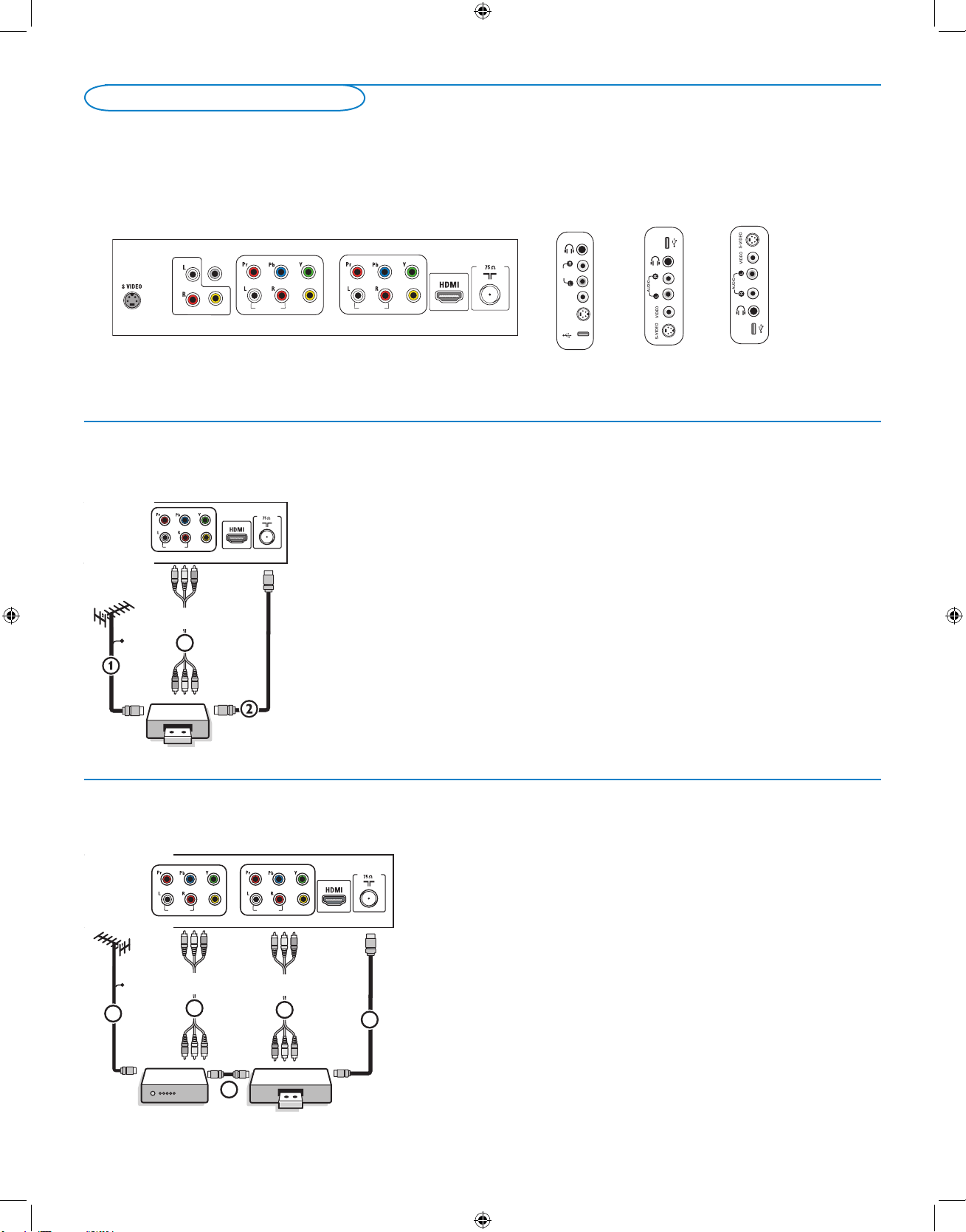
There is a wide range of audio and video devices that can be connected to your TV. The following connection diagrams show you how to
connect them to the TV.
AV1 and AV2 can handle YPbPr or VIDEO and L/R Audio,
AV3 VIDEO or S-VIDEO and L/R Audio and Digital Audio Out (SPDIF OUT),
Side VIDEO or S-VIDEO and L/R Audio.
Connect Accessory Devices
file : conn us top05 vcr -tv g.eps
RECORDER
OUTIN
OUT
3
AV1 :
L + R + VIDE
O
CABLE
AUDIO IN
VIDEO IN
AV
1
Recorder (VCR / DVD+RW)
Note: Do not place your recorder too close to the screen as some recorders may be
susceptible for signals from the display. Keep a minimum distance of 20” from the screen.
& Connect the RF Antenna or Cable TV cable (eventually via an optional two-way
signal splitter and/or Cable TV converter box)
1 to the RF IN socket of your
recorder.
é Connect another RF cable 2 from the output OUT of your recorder to the
TV’s CABLE/ANTENNA 75 Ω x jack.
“ Better playback quality can be obtained if you also connect the Video, Audio Left
and Right (only for stereo devices) AV cables
3 to the VIDEO, AUDIO L and
R input jacks of AV1.
If your recorder has an S-VHS video jack:
For improved picture quality, connect an S-video cable to the
S-VIDEO input of
AV3 instead of connecting the recorder to the
VIDEO jack of AV1.
S-Video does not provide audio, so audio cables must still be connected to
Audio L and R of AV3 to provide sound.
c on n u s e ntr y0 5 v cr&a v 1 .e ps
RECORDER
OUTIN
CABLE
OUTIN
OUT
1
2
AV1 :
L + R + VIDEO
3
AV2 :
L + R + VIDE
O
5
4
AUDIO IN
VIDEO IN
AV
1
AV
2
AUDIO IN
VIDEO IN
& Connect the RF antenna cable 1 of the RF IN socket of your other AV device.
é Connect the RF output of the AV device to the RF input of the recorder 2.
“ Connect another RF cable 4 from the output OUT of your recorder to the
TV’s input
CABLE/ANTENNA 75 Ω x jack.
‘ To obtain better quality, also connect the Video, Audio left and Audio right cables
of both devices to
AV1 (VIDEO and
AUDIO L and R,) 5 and to AV2 (VIDEO and AUDIO L and R) 3.
Notes:
- In case of mono equipment, only the left loudspeaker reproduces sound.
Use a mono to stereo adapter (not supplied) for sound reproduction via all internal
loudspeakers.
- When using the
S-VIDEO connector do not connect any device to the AV3 VIDEO input.
Recorder and other A/V devices
26PF5321D
32PF5321D
32PF7321D
37PF7321D
42PF7421D
42PF5321D
42PF7321D
50PF7321D
all conn us st-entr05-glink.eps
LPrH
RPbV
INY
Pr
PbL
YR
S-VIDEO
S-VIDE
O
AV2
AV
3
AV1
VIDEO
VIDEO
Cable CARD INTERFACE HDMI HDMI
1 2
ANTENNA
75
R
L
VIDEO
IR OU
T
DIGITAL
OUT
AUDIO
MONITOR OUT
VIDEO IN
AV
3
AUDIO IN
VIDEO IN
AV
1
AV
2
AUDIO IN
VIDEO IN
USB
USB
USB
AUDIO
IN
VIDEO
IN
S-VIDE
O
IN
SPDIF
OUT
English_DFU_35242.indd 20 2005-11-27 3:30:42 PM
Loading ...
Loading ...
Loading ...