[M/flSTEAF,iJRl:£4®
[A
J
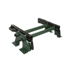
Universal Quick-Mount Tool Station
240-1675
OPERATOR’S MANUAL
CAUTION:
To Reduce The Risk Of Injury, User Must Read And
Understand Operator’s Manual. Save These Instructions For Future Reference.
© 2016 Menard, Inc., Eau Claire, WI 54703
03/14/2017

IA
TABLE OF CONTENTS NOTES
Save this Manual.............................................................................. Page 1
General Safety Information............................................................... Page 1
Work Area Safety.............................................................................. Page 1
Personal Safety.................................................................................Page 2
Tool Use and Page 2
Care............................................................................ Page 3
Safety Instructions for Power Page 3
Tools................................................... Page 4
Parts List.......................................................................................... Page 5
Assembly Instructions...................................................................... Page 8
Mounting Instructions....................................................................... Page 9
Warranty...........................................................................................
SAVE THIS MANUAL
Reference this manual for all safety warnings and precautions, operating and maintenance
procedures, parts list and diagrams. Keep your invoice with this manual and write your invoice
number on the inside of the front cover. Keep the manual and invoice in a safe, dry place for
future reference.
WARNING:
Be sure to read and understand all safety instructions in this manual,
including all safety alert symbols such as "danger'', "warning", and "caution" before using
this tool. Failure to follow all instructions may result in serious personal injury.
GENERAL SAFETY INFORMATION
For your safety, please read these instructions carefully before use and keep them in the area
where your tools will be used. Failure to follow all instructions listed below may result in electric
shock, fire, and/or serious personal injury.
WORK AREA SAFETY
• Always work in a clean and well lit area.
• Avoid distractions by keeping bystanders, children, and visitors away while operating a tool.
• Keep floors dry and free of slippery materials that may invite accidents.
• Do not operate power tools in explosive atmospheres, such as in the presence of flammable
liquids, gases, or dust. Tools create sparks which may ignite the dust or fumes.
Page 1
Page 14

PERSONAL SAFETY
NOTES
Page 13
• Stay alert, watch what you are doing and use common sense when operating near power
tools. Do not use tools while tired or under the influence of drugs, alcohol, or medications.
A moment of inattention while operating power tools may result in serious personal injury.
• Dress properly. Do not wear loose clothing or jewelry.
• Contain long hair. Keep your hair, clothing, and gloves away from moving parts. Loose
clothes, jewelry, or long hair can be caught in moving parts.
• Avoid accidental starting. Be sure switch is OFF before plugging in. Carrying tools with
your finger on the switch or plugging in tools that have the switch ON invites accidents.
• Always use safety equipment and wear eye protection.
• Dust masks, non-skid safety shoes, hard hats, or hearing protection should be used for
appropriate conditions.
TOOL USE AND CARE
• Disconnect electrical plugs from the power source before making any tool adjustments to
reduce the risk of inadvertent tool starts.
• Store idle tools out of the reach of children and other untrained persons. Tools are
dangerous in the hands of untrained users.
• Always inspect tools for conditions that may affect operation. Many accidents are caused
by poorly maintained tools.
• Keep tool handles clean, dry and free from oil or grease to allow for better control
of the tool.
• Grounded tools must be plugged into an outlet, properly installed and grounded in
accordance with all codes and ordinances. Never remove the grounding prong or modify
the plug in any way. Do not use any adapter plugs. Check with a qualified electrician if you
are in doubt as to whether the outlet is properly grounded. If the tool should electrically
malfunction or break down, grounding provides a low resistance path to carry electricity
away from the user.
• Avoid body contact with grounded surfaces. There is an increased risk of electrical shock if
your body is grounded.
• Don’t expose electrical tools to rain or wet conditions. Water entering a tool will increase the
risk of electrical shock.
• Do not abuse cords! Never use the cord to pull the plug from an outlet. Keep cord away
from heat, oil, sharp edges or moving parts. Replace damaged cords immediately.
Damaged cords increase the risk of electrical shock.
• When operating a power tool outside, use an outdoor extension cord marked “W-A” or “W.”
These cords are rated for outdoor use and reduce the risk of electrical shock.
• Use only three-wire extension cords which have three-prong grounding plugs and
three-pole receptacles which accept the tool’s plug. Use of other extension cords will not
ground the tool and increase the risk of electrical shock.
• Dust masks, non-skid safety shoes, hard hats, or hearing protection should be used for
appropriate conditions.
Page 2

3-YEAR LIMITED WARRANTY
PARTS LIST
IA
SAFETY INSTRUCTIONS FOR POWER TOOLS
Using power tools can be dangerous if safe operating procedures are not followed.
Recognizing the hazards of each tool and using them with respect and caution considerably
limits the possibility of personal injury. However, if safety precautions are ignored, personal
injury will likely result. Always use common sense – your personal safety is your responsibility.
1. Know your power tool. Read and understand the Product Manual and observe the
warnings and instruction labels affixed to the tool.
2. Remove adjusting keys and wrenches.
3. Keep work area clean and dry.
4. Keep children away.
5. Wear safety glasses or goggles.
6. Never stand or sit on tools.
7. Replace damaged components immediately.
8. Make sure your work platform is sufficiently sturdy to do the specific job at hand.
WARNING:
If you are mounting power tools to your oversized tool accessory mount, then
make sure it is well-balanced and well-secured to your workstation to insure it is stable and
safe to use.
Universal Quick-Mount Tool Station
WARRANTY
90-DAY MONEY BACK GUARANTEE
This MASTERFORCE
®
brand tool carries our 90-Day Money Back Guarantee.
If you are not completely satisfied with your MASTERFORCE
®
brand power tool for
any reason within ninety (90) days from the date of purchase, return the tool with your
original receipt to any MENARDS
®
retail store, and we will provide you a refund - no
questions asked.
This MASTERFORCE
®
brand tool carries our famous No Hassle 3-Year Limited
Warranty to the original purchaser. If, during normal use, this MASTERFORCE
®
power
tool breaks or fails due to a defect in material or workmanship, simply bring the tool with
the original sales receipt back to your nearest MENARDS
®
retail store. At its discretion,
MASTERFORCE
®
agrees to have the tool or any defective part(s) repaired or replaced
with the same or similar MASTERFORCE
®
product or part free of charge, within the
stated warranty period, when returned by the original purchaser with original sales
receipt. Not withstanding the foregoing, this 3-year limited warranty does not cover any
damage that has resulted from abuse or misuse of the Merchandise. This warranty: (1)
excludes expendable parts including but not limited to blades, brushes, belts, bits, light
bulbs, and/or batteries; (2) shall be void if this tool is used for commercial and/or rental
purposes; and (3) does not cover any losses, injuries to persons/property or costs. This
warranty does give you specific legal rights and you may have other rights, which vary
from state to state. Be careful, tools are dangerous if improperly used or maintained.
Seller’s employees are not qualified to advise you on the use of this merchandise. Any
oral representation(s) made will not be binding on seller or its employees. The rights
under this 3-year limited warranty are to the original purchaser of the merchandise and
may not be transferred to any subsequent owner. This 3-year limited warranty is in lieu
of all warranties, expressed or implied including warranties or merchantability and fitness
for a particular purpose. Seller shall not be liable for any special, incidental, or
consequential damages. The sole exclusive remedy against the seller will be for the
replacement of any defects as provided herein, as long as the seller is willing or able to
replace this product or is willing to refund the purchase price as provided above. For
insurance purposes seller is not allowed to demonstrate any of these power tools for you.
For questions / comments, technical assistance or repair parts -
Please call toll free at: 1-800-255-7011 (M-F 8am - 6pm CST)
SAVE YOUR RECEIPTS
THIS WARRANTY IS VOID WITHOUT THEM
Page 12
Page 3
PARTS LIST
0 0 0
0
0
0
1
2
3
4
9
5
6
7
8
10
Tool Mount
Adjustment Screw
'*''
Wrench
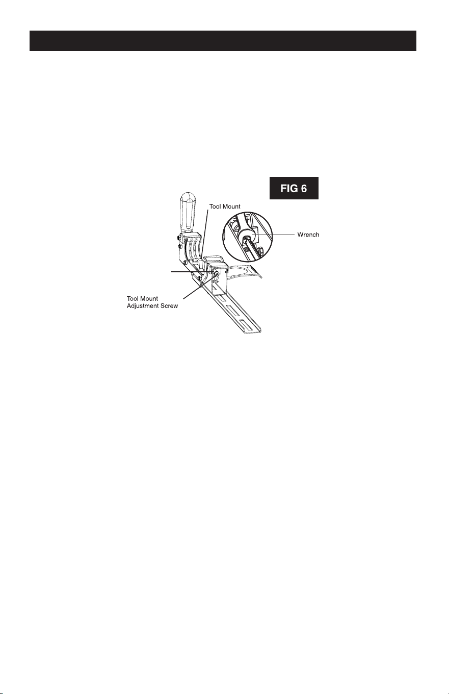
MAINTENANCE
TO ADJUST:
1. Use a wrench to slightly loosen the nut.
2. Turn the screw with a Phillips screwdriver. Rotate clockwise, if the tool mount assembly needs to
be tightened. Rotate counterclockwise if the assembly needs to be loosened. See Figure 6.
3. Install the tool mount on the miter stand rails and lower the locking lever to check the adjustment.
4. When the correct position is achieved, wrench tighten the nut to secure.
5. Repeat with the second tool mount.
M8 Nut
GENERAL MAINTENANCE
Avoid using solvents when cleaning. Most items are susceptible to damage from various types
of commercial solvents. Use clean clothes to remove dirt, dust, oil, grease, etc.
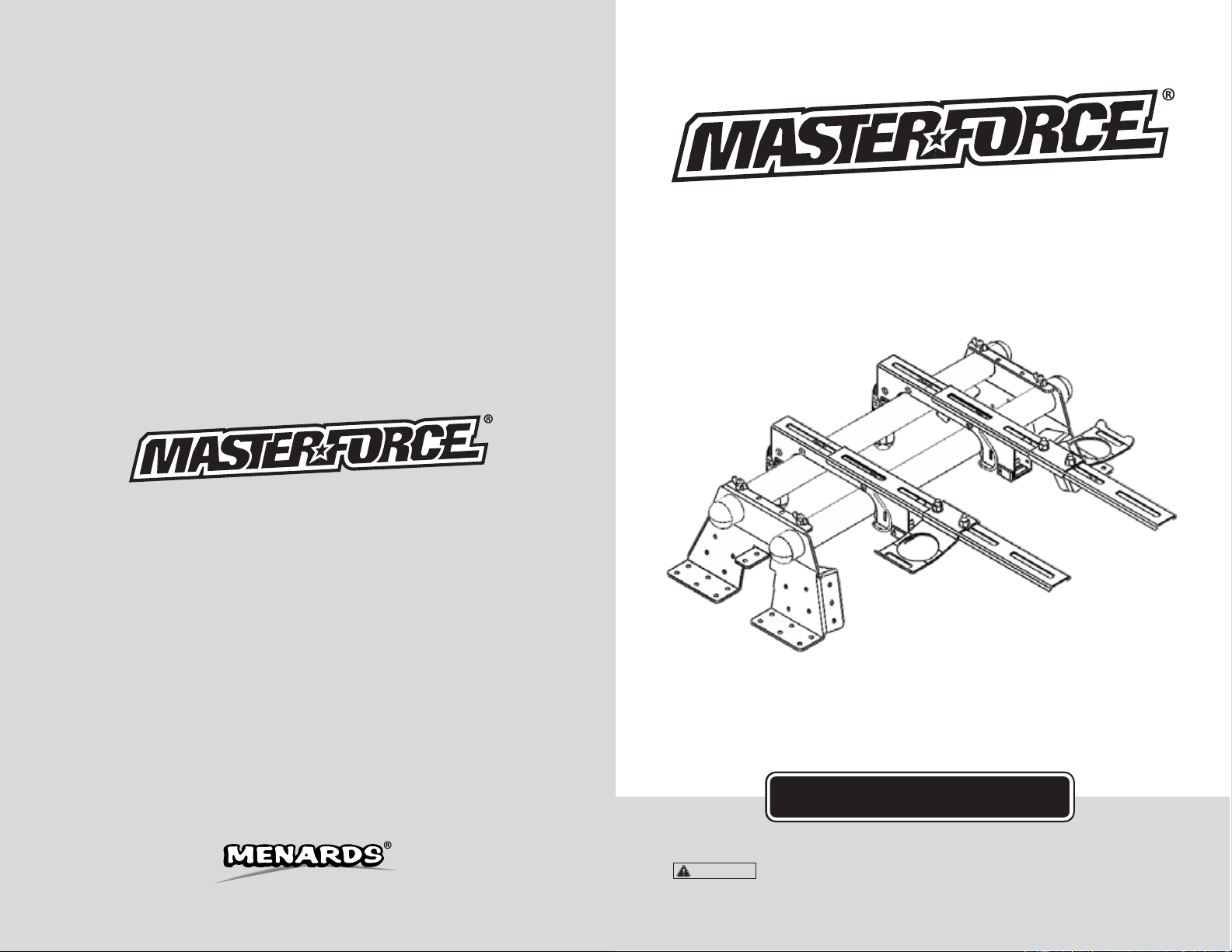
PART #
1
2
3
4
5
6
7
8
9
10
DESCRIPTION
Rapid Clamp Tool Mounts
Offset Mounting Brackets
Nut M8
Spring Washer #8
Washer #8
Carriage Bolt M8*50
Carriage Bolt M8*20
Storage Handles
Mounting Plates
Mounting Beams
QTY
1 set
2 pcs
10 pcs
10 pcs
10 pcs
4 pcs
6 pcs
2 pcs
2 pcs
2 pcs
Page 11
Page 4
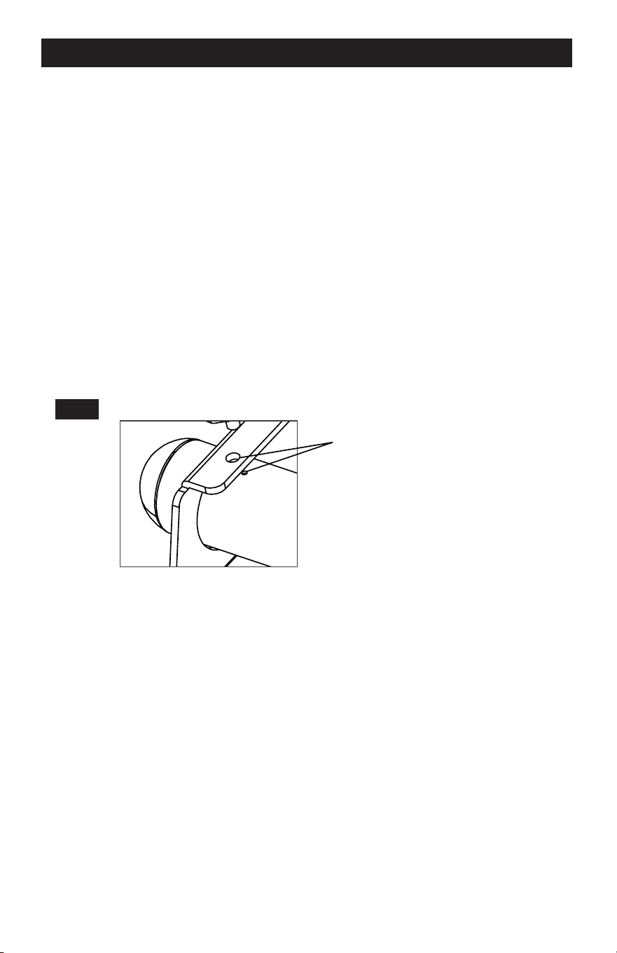
FIG 1
-
ASSEMBLY INSTRUCTIONS
MOUNTING INSTRUCTIONS
Required Tools: Phillips Head Screwdriver, Hex Key Wrench (Included), Box Wrench
2x4 Mounted Sawhorse Mounted
1. Carefully remove the contents of the box and place the
materials on a flat surface (table, floor, etc.).
2. Identify the included parts: Mounting Beams (2), Rapid
Clamp Tool Mounts (2), Mounting Plates (2) and Hardware.
NOTE
The hardware packet includes:
Carriage Bolts with Nuts (4),
Flat Washers (4), Lock Washers (4)
Locating Screws and Nuts (4),
Hex Key Wrench (1)
3. Slide both Mounting Beams through the large holes in
one of the Mounting Plates until the smaller locating
holes in the Mounting Beam align with the holes in the
Work Tables Wall Mounted
Mounting Plates. Repeat for the opposite side.
Smaller Locating holes
Freestanding
4. Thread the nuts onto the Locating Screws until flush with the head of the bolt.
5. Using the supplied Hex Key Wrench, thread the Locating Screws into the holes in the
Mounting Bracket until they stop.
NOTE
The two holes in either end of the Mounting Beams are intentionally not large enough to accept
the shaft of the Locating Screws. DO NOT ATTEMPT TO MAKE THESE HOLES LARGER. The
purpose of these holes is only to have a visual confirmation of proper alignment for wall
mounting scenarios.
6. Using a Box Wrench, turn the nuts on the Locating Screws clockwise until snug. The nuts
serve to keep the screws from backing out of the holes and becoming loose.
Page 5
Page 10
-
l
g
MOUNTING INSTRUCTIONS
e. Swing the pivoting handles downward into the closed position perpendicular to the body
of the Rapid Clamp Mounts.
f. Snap the J-Lock
™
closed (forward) around the beams to prevent your mounted tool from
detaching from the Masterforce
®
Universal Quick-Mount Tool Station.
4. Surfaces/work tables
a. Place the Mounting Plates onto your intended mounting surface (See Fig. 1, Pg.3). With a
marker, trace the inside of the machined holes. Remove the plates and pre-drill holes for
mounting hardware. Then align bolt mounting holes with pre-drilled holes.
b. Use appropriate mounting hardware to attach the Universal Quick-Mount Tool Station to
the frame (not included). Holes are drilled into the metal framework for this purpose. Be
sure not to over tighten.
c. With the black Rapid Clamp Handles in the open position (parallel to the body of the
Rapid Clamp Mounts), place them onto the Mounting Beams. These handles pivot with
a 90-degree arc.
d. Lock the Mounts onto the back Mounting Beam first, and then the front (the handles will be
farthest away from you).
e. Swing the pivoting handles downward into the closed position perpendicular to the body
of the Rapid Clamp Mounts.
f. Snap the J-Lock
™
closed (forward) around the beams to prevent your mounted tool from
detaching from the Masterforce
®
Universal Quick-Mount Tool Station.
FIG 2
5. Freestanding
a. Ensure the black Rapid Clamp Handles are in the open position (parallel to the body of
the Rapid Clamp Mounts), and place them onto the Mounting Beams. These handles
pivot with a 90-degree arc.
b. Lock the Mounts onto the back Mounting Beam first, and then the front (the handles will
be farthest away from you).
c. Swing the pivoting handles downward into the closed position perpendicular to the body
of the Rapid Clamp Mounts.
d. Snap the J-Lock
™
closed (forward) around the beams to prevent your mounted tool from
detaching from the Masterforce
®
Universal Quick-Mount Tool Station.
Page 9
ASSEMBLY INSTRUCTIONS
ATTACHING YOUR MITER SAW OR OTHER BENCH TOP POWER TOOLS
Various bench top tools can be attached to the Rapid Clamp Tool Mounts. Always position the
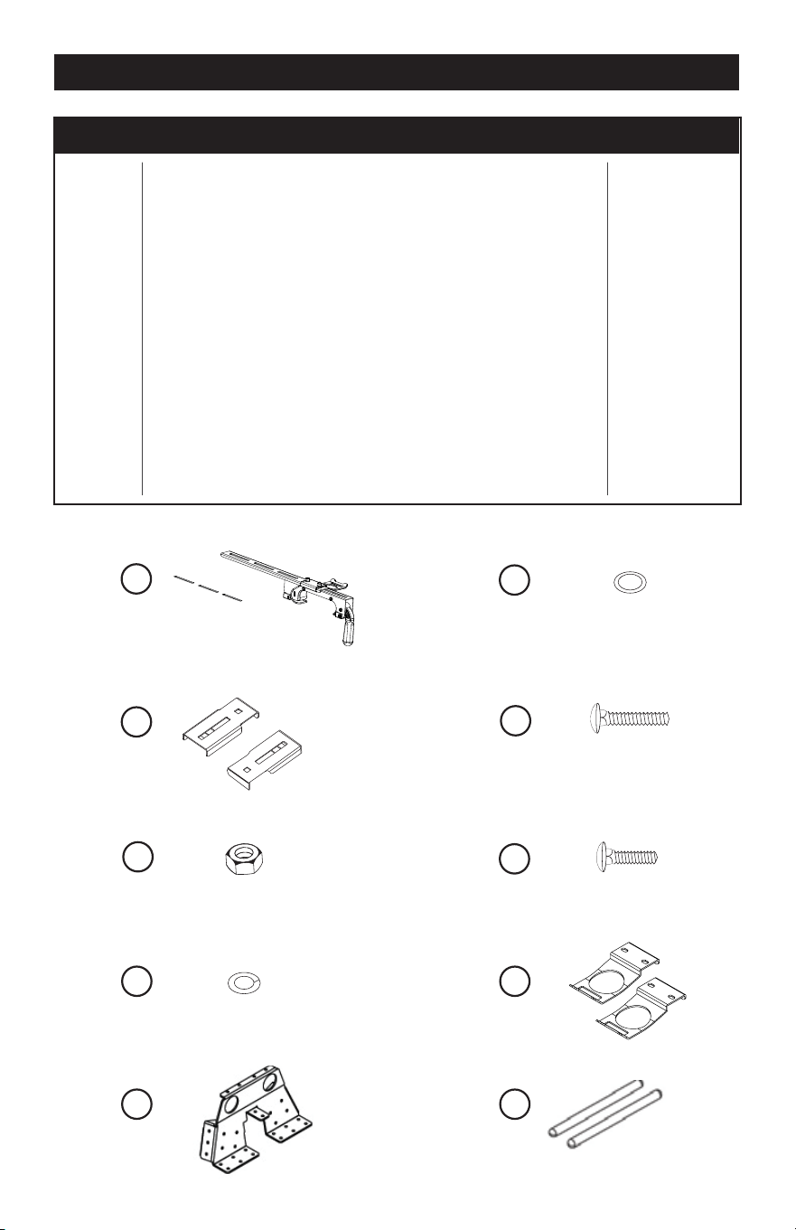
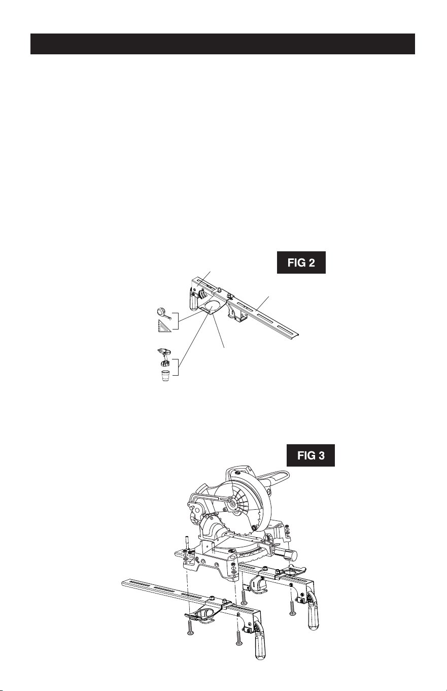
tool to achieve maximum balance and stability. All four corners of the saw must be bolted to the
tool mounts before use. Make sure the bolts do not extend above the table of the miter saw.
1. Unplug all tools and lock down any moving parts.
2. Select a Storage Handle and position it where desired on one mounting rail. Run two
M8*20 Carriage Bolts through the slots in the rail arms and attach using a #8 washer and
nut. These handles are designed to store tools and can be located where most convenient
for the user by sliding it along the rail. See Figure 2. Tighten the bolts and repeat for the
second arm. The handles should face opposite directions (outward) when the two
completed arms are next to each other.
Rapid Clamp Tool
Mount Base
Rapid Clamp Tool
Mounting Rail
Rapid Clamp Tool
Handle and Tool
Storage Arm
3. Feed a carriage bolt up through the tool mount and the mounting hole in the power tool.
See Figure 3.
4. Secure in place using a flat washer, lock washer and nut.
Page 6
5. Repeat through the other end of the tool mount.
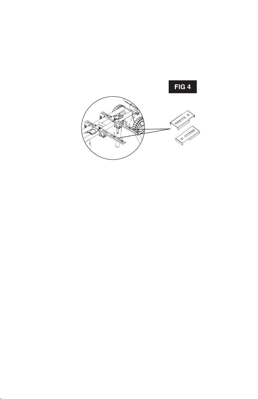
6. Place the second tool mount underneath the other side of the tool, aligning the mounting
holes and repeat steps 1 thru 5 on the miter saw base with the opening in the tool mount.
7. After making sure both tool mounts are parallel to each other, tighten all four nuts to hold in
position.
NOTE: If the tool has holes that do not line up with the slots in the tool mounts, then use the
Offset Mounting Brackets. See Figure 4.
Offset Mounting Brackets
Page 7
MOUNTING INSTRUCTIONS
IMPORTANT: Prior to mounting your 5-in-1 to a stand or surface, first attach your power tool to
both Rapid Clamp Tool Mounts with the black, bolted-on handles facing outward. Install a
washer onto the larger bolts (included). Insert the bolts through the holes on your power tool
and then through the slats in the Rapid Clamp Mounts. Finish by installing a Lock Washer and
Nut, and then tighten with a 3/8" Box Wrench. Repeat until your tool is secured.
Next, mount your 5-in-1 bracket according to the intended use:
1. Miter saw installations
a. Ensure the black Rapid Clamp Handles are in the open position (parallel to the body of the
Rapid Clamp Mounts) and place them onto the Mounting Beams. These handles pivot
with a 90-degree arc.
b. Lock the Mounts onto the back Mounting Beam first, and then the front (the handles will be
farthest away from you).
c. Swing the pivoting handles downward into the closed position perpendicular to the body
of the Rapid Clamp Mounts.
d. Snap the J-Lock
™
closed (forward) around the beams to prevent your mounted tool from
detaching from the Masterforce
®
5-ln-1 Miter Saw Station.
2. Wall-mounting scenarios
a. Use only the Rapid Clamp Tool Mounts included with this kit featuring the J-Lock
™
Clip.
Without this unique clip, it is possible that your tool could become dislodged from the
mount if bumped.
b. Ensure the black Rapid Clamp Handles are in the open position (parallel to the body of the
Rapid Clamp Mounts) and place them onto the Mounting Beams.
c. Holding the Rapid Clamp Tool Mounts with the pivoting handles facing upward, hold the
assembly by the outward-facing permanent handles and place the unit onto the top
Mounting Beam.
d. Next, firmly press the bottom portion into place until it snaps onto the beam.
e. Swing the top handles forward (away from you) into the closed position perpendicular to
the body of the Rapid Clamp Mounts.
f. Snap the J-Lock
™
closed (downward) around the beams to prevent your mounted tool from
detaching from the Masterforce
®
5-ln-1 Miter Saw Station.
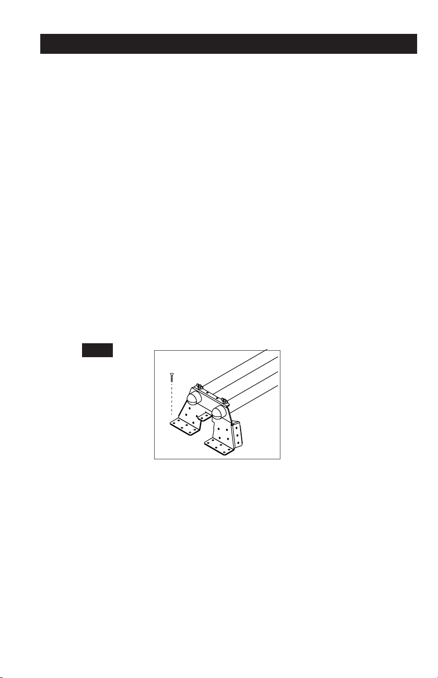
3. Saw horses/2x4’s
a. Place the Universal Quick-Mount Tool Station over the MX042 or MX047 saw horse. When
installed correctly, the square-shaped hole in the bracket will straddle the top of the
sawhorse.
b. For wooden saw horses or 2x4 installations, use wood screws or similar hardware to
attach the Universal Quick-Mount Tool Station to the frame (not included). Holes are
drilled into the metal framework for this purpose.
c. Ensure the black Rapid Clamp Handles are in the open position (parallel to the body of the
Rapid Clamp Mounts) and place them onto the Mounting Beams. These handles pivot
with a 90-degree arc.
d. Lock the Mounts onto the back Mounting Beam first, and then the front (the handles will be
farthest away from you).
Page 8

5. Repeat through the other end of the tool mount.
6. Place the second tool mount underneath the other side of the tool, aligning the mounting
holes and repeat steps 1 thru 5 on the miter saw base with the opening in the tool mount.
7. After making sure both tool mounts are parallel to each other, tighten all four nuts to hold in
position.
NOTE: If the tool has holes that do not line up with the slots in the tool mounts, then use the
Offset Mounting Brackets. See Figure 4.
Offset Mounting Brackets
Page 7
MOUNTING INSTRUCTIONS
IMPORTANT: Prior to mounting your 5-in-1 to a stand or surface, first attach your power tool to
both Rapid Clamp Tool Mounts with the black, bolted-on handles facing outward. Install a
washer onto the larger bolts (included). Insert the bolts through the holes on your power tool
and then through the slats in the Rapid Clamp Mounts. Finish by installing a Lock Washer and
Nut, and then tighten with a 3/8" Box Wrench. Repeat until your tool is secured.
Next, mount your 5-in-1 bracket according to the intended use:
1. Miter saw installations
a. Ensure the black Rapid Clamp Handles are in the open position (parallel to the body of the
Rapid Clamp Mounts) and place them onto the Mounting Beams. These handles pivot
with a 90-degree arc.
b. Lock the Mounts onto the back Mounting Beam first, and then the front (the handles will be
farthest away from you).
c. Swing the pivoting handles downward into the closed position perpendicular to the body
of the Rapid Clamp Mounts.
d. Snap the J-Lock
™
closed (forward) around the beams to prevent your mounted tool from
detaching from the Masterforce
®
5-ln-1 Miter Saw Station.
2. Wall-mounting scenarios
a. Use only the Rapid Clamp Tool Mounts included with this kit featuring the J-Lock
™
Clip.
Without this unique clip, it is possible that your tool could become dislodged from the
mount if bumped.
b. Ensure the black Rapid Clamp Handles are in the open position (parallel to the body of the
Rapid Clamp Mounts) and place them onto the Mounting Beams.
c. Holding the Rapid Clamp Tool Mounts with the pivoting handles facing upward, hold the
assembly by the outward-facing permanent handles and place the unit onto the top
Mounting Beam.
d. Next, firmly press the bottom portion into place until it snaps onto the beam.
e. Swing the top handles forward (away from you) into the closed position perpendicular to
the body of the Rapid Clamp Mounts.
f. Snap the J-Lock
™
closed (downward) around the beams to prevent your mounted tool from
detaching from the Masterforce
®
5-ln-1 Miter Saw Station.
3. Saw horses/2x4’s
a. Place the Universal Quick-Mount Tool Station over the MX042 or MX047 saw horse. When
installed correctly, the square-shaped hole in the bracket will straddle the top of the
sawhorse.
b. For wooden saw horses or 2x4 installations, use wood screws or similar hardware to
attach the Universal Quick-Mount Tool Station to the frame (not included). Holes are
drilled into the metal framework for this purpose.
c. Ensure the black Rapid Clamp Handles are in the open position (parallel to the body of the
Rapid Clamp Mounts) and place them onto the Mounting Beams. These handles pivot
with a 90-degree arc.
d. Lock the Mounts onto the back Mounting Beam first, and then the front (the handles will be
farthest away from you).
Page 8
-
l
g
MOUNTING INSTRUCTIONS
e. Swing the pivoting handles downward into the closed position perpendicular to the body
of the Rapid Clamp Mounts.
f. Snap the J-Lock
™
closed (forward) around the beams to prevent your mounted tool from
detaching from the Masterforce
®
Universal Quick-Mount Tool Station.
4. Surfaces/work tables
a. Place the Mounting Plates onto your intended mounting surface (See Fig. 1, Pg.3). With a
marker, trace the inside of the machined holes. Remove the plates and pre-drill holes for
mounting hardware. Then align bolt mounting holes with pre-drilled holes.
b. Use appropriate mounting hardware to attach the Universal Quick-Mount Tool Station to
the frame (not included). Holes are drilled into the metal framework for this purpose. Be
sure not to over tighten.
c. With the black Rapid Clamp Handles in the open position (parallel to the body of the
Rapid Clamp Mounts), place them onto the Mounting Beams. These handles pivot with
a 90-degree arc.
d. Lock the Mounts onto the back Mounting Beam first, and then the front (the handles will be
farthest away from you).
e. Swing the pivoting handles downward into the closed position perpendicular to the body
of the Rapid Clamp Mounts.
f. Snap the J-Lock
™
closed (forward) around the beams to prevent your mounted tool from
detaching from the Masterforce
®
Universal Quick-Mount Tool Station.
FIG 2
5. Freestanding
a. Ensure the black Rapid Clamp Handles are in the open position (parallel to the body of
the Rapid Clamp Mounts), and place them onto the Mounting Beams. These handles
pivot with a 90-degree arc.
b. Lock the Mounts onto the back Mounting Beam first, and then the front (the handles will
be farthest away from you).
c. Swing the pivoting handles downward into the closed position perpendicular to the body
of the Rapid Clamp Mounts.
d. Snap the J-Lock
™
closed (forward) around the beams to prevent your mounted tool from
detaching from the Masterforce
®
Universal Quick-Mount Tool Station.
Page 9
ASSEMBLY INSTRUCTIONS
ATTACHING YOUR MITER SAW OR OTHER BENCH TOP POWER TOOLS
Various bench top tools can be attached to the Rapid Clamp Tool Mounts. Always position the
tool to achieve maximum balance and stability. All four corners of the saw must be bolted to the
tool mounts before use. Make sure the bolts do not extend above the table of the miter saw.
1. Unplug all tools and lock down any moving parts.
2. Select a Storage Handle and position it where desired on one mounting rail. Run two
M8*20 Carriage Bolts through the slots in the rail arms and attach using a #8 washer and
nut. These handles are designed to store tools and can be located where most convenient
for the user by sliding it along the rail. See Figure 2. Tighten the bolts and repeat for the
second arm. The handles should face opposite directions (outward) when the two
completed arms are next to each other.
Rapid Clamp Tool
Mount Base
Rapid Clamp Tool
Mounting Rail
Rapid Clamp Tool
Handle and Tool
Storage Arm
3. Feed a carriage bolt up through the tool mount and the mounting hole in the power tool.
See Figure 3.
4. Secure in place using a flat washer, lock washer and nut.
Page 6
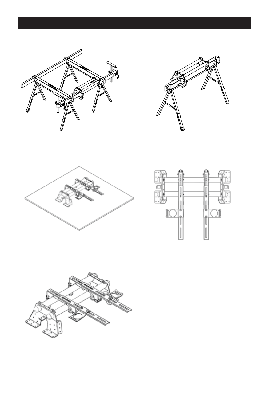
FIG 1
-
ASSEMBLY INSTRUCTIONS
MOUNTING INSTRUCTIONS
Required Tools: Phillips Head Screwdriver, Hex Key Wrench (Included), Box Wrench
2x4 Mounted Sawhorse Mounted
1. Carefully remove the contents of the box and place the
materials on a flat surface (table, floor, etc.).
2. Identify the included parts: Mounting Beams (2), Rapid
Clamp Tool Mounts (2), Mounting Plates (2) and Hardware.
NOTE
The hardware packet includes:
Carriage Bolts with Nuts (4),
Flat Washers (4), Lock Washers (4)
Locating Screws and Nuts (4),
Hex Key Wrench (1)
3. Slide both Mounting Beams through the large holes in
one of the Mounting Plates until the smaller locating
holes in the Mounting Beam align with the holes in the
Work Tables Wall Mounted
Mounting Plates. Repeat for the opposite side.
Smaller Locating holes
Freestanding
4. Thread the nuts onto the Locating Screws until flush with the head of the bolt.
5. Using the supplied Hex Key Wrench, thread the Locating Screws into the holes in the
Mounting Bracket until they stop.
NOTE
The two holes in either end of the Mounting Beams are intentionally not large enough to accept
the shaft of the Locating Screws. DO NOT ATTEMPT TO MAKE THESE HOLES LARGER. The
purpose of these holes is only to have a visual confirmation of proper alignment for wall
mounting scenarios.
6. Using a Box Wrench, turn the nuts on the Locating Screws clockwise until snug. The nuts
serve to keep the screws from backing out of the holes and becoming loose.
Page 5
Page 10
PARTS LIST
0 0 0
0
0
0
1
2
3
4
9
5
6
7
8
10
Tool Mount
Adjustment Screw
'*''
Wrench
MAINTENANCE
TO ADJUST:
1. Use a wrench to slightly loosen the nut.
2. Turn the screw with a Phillips screwdriver. Rotate clockwise, if the tool mount assembly needs to
be tightened. Rotate counterclockwise if the assembly needs to be loosened. See Figure 6.
3. Install the tool mount on the miter stand rails and lower the locking lever to check the adjustment.
4. When the correct position is achieved, wrench tighten the nut to secure.
5. Repeat with the second tool mount.
M8 Nut
GENERAL MAINTENANCE
Avoid using solvents when cleaning. Most items are susceptible to damage from various types
of commercial solvents. Use clean clothes to remove dirt, dust, oil, grease, etc.
PART #
1
2
3
4
5
6
7
8
9
10
DESCRIPTION
Rapid Clamp Tool Mounts
Offset Mounting Brackets
Nut M8
Spring Washer #8
Washer #8
Carriage Bolt M8*50
Carriage Bolt M8*20
Storage Handles
Mounting Plates
Mounting Beams
QTY
1 set
2 pcs
10 pcs
10 pcs
10 pcs
4 pcs
6 pcs
2 pcs
2 pcs
2 pcs
Page 11
Page 4

3-YEAR LIMITED WARRANTY
PARTS LIST
IA
SAFETY INSTRUCTIONS FOR POWER TOOLS
Using power tools can be dangerous if safe operating procedures are not followed.
Recognizing the hazards of each tool and using them with respect and caution considerably
limits the possibility of personal injury. However, if safety precautions are ignored, personal
injury will likely result. Always use common sense – your personal safety is your responsibility.
1. Know your power tool. Read and understand the Product Manual and observe the
warnings and instruction labels affixed to the tool.
2. Remove adjusting keys and wrenches.
3. Keep work area clean and dry.
4. Keep children away.
5. Wear safety glasses or goggles.
6. Never stand or sit on tools.
7. Replace damaged components immediately.
8. Make sure your work platform is sufficiently sturdy to do the specific job at hand.
WARNING:
If you are mounting power tools to your oversized tool accessory mount, then
make sure it is well-balanced and well-secured to your workstation to insure it is stable and
safe to use.
Universal Quick-Mount Tool Station
WARRANTY
90-DAY MONEY BACK GUARANTEE
This MASTERFORCE
®
brand tool carries our 90-Day Money Back Guarantee.
If you are not completely satisfied with your MASTERFORCE
®
brand power tool for
any reason within ninety (90) days from the date of purchase, return the tool with your
original receipt to any MENARDS
®
retail store, and we will provide you a refund - no
questions asked.
This MASTERFORCE
®
brand tool carries our famous No Hassle 3-Year Limited
Warranty to the original purchaser. If, during normal use, this MASTERFORCE
®
power
tool breaks or fails due to a defect in material or workmanship, simply bring the tool with
the original sales receipt back to your nearest MENARDS
®
retail store. At its discretion,
MASTERFORCE
®
agrees to have the tool or any defective part(s) repaired or replaced
with the same or similar MASTERFORCE
®
product or part free of charge, within the
stated warranty period, when returned by the original purchaser with original sales
receipt. Not withstanding the foregoing, this 3-year limited warranty does not cover any
damage that has resulted from abuse or misuse of the Merchandise. This warranty: (1)
excludes expendable parts including but not limited to blades, brushes, belts, bits, light
bulbs, and/or batteries; (2) shall be void if this tool is used for commercial and/or rental
purposes; and (3) does not cover any losses, injuries to persons/property or costs. This
warranty does give you specific legal rights and you may have other rights, which vary
from state to state. Be careful, tools are dangerous if improperly used or maintained.
Seller’s employees are not qualified to advise you on the use of this merchandise. Any
oral representation(s) made will not be binding on seller or its employees. The rights
under this 3-year limited warranty are to the original purchaser of the merchandise and
may not be transferred to any subsequent owner. This 3-year limited warranty is in lieu
of all warranties, expressed or implied including warranties or merchantability and fitness
for a particular purpose. Seller shall not be liable for any special, incidental, or
consequential damages. The sole exclusive remedy against the seller will be for the
replacement of any defects as provided herein, as long as the seller is willing or able to
replace this product or is willing to refund the purchase price as provided above. For
insurance purposes seller is not allowed to demonstrate any of these power tools for you.
For questions / comments, technical assistance or repair parts -
Please call toll free at: 1-800-255-7011 (M-F 8am - 6pm CST)
SAVE YOUR RECEIPTS
THIS WARRANTY IS VOID WITHOUT THEM
Page 12
Page 3

PERSONAL SAFETY
NOTES
Page 13
• Stay alert, watch what you are doing and use common sense when operating near power
tools. Do not use tools while tired or under the influence of drugs, alcohol, or medications.
A moment of inattention while operating power tools may result in serious personal injury.
• Dress properly. Do not wear loose clothing or jewelry.
• Contain long hair. Keep your hair, clothing, and gloves away from moving parts. Loose
clothes, jewelry, or long hair can be caught in moving parts.
• Avoid accidental starting. Be sure switch is OFF before plugging in. Carrying tools with
your finger on the switch or plugging in tools that have the switch ON invites accidents.
• Always use safety equipment and wear eye protection.
• Dust masks, non-skid safety shoes, hard hats, or hearing protection should be used for
appropriate conditions.
TOOL USE AND CARE
• Disconnect electrical plugs from the power source before making any tool adjustments to
reduce the risk of inadvertent tool starts.
• Store idle tools out of the reach of children and other untrained persons. Tools are
dangerous in the hands of untrained users.
• Always inspect tools for conditions that may affect operation. Many accidents are caused
by poorly maintained tools.
• Keep tool handles clean, dry and free from oil or grease to allow for better control
of the tool.
• Grounded tools must be plugged into an outlet, properly installed and grounded in
accordance with all codes and ordinances. Never remove the grounding prong or modify
the plug in any way. Do not use any adapter plugs. Check with a qualified electrician if you
are in doubt as to whether the outlet is properly grounded. If the tool should electrically
malfunction or break down, grounding provides a low resistance path to carry electricity
away from the user.
• Avoid body contact with grounded surfaces. There is an increased risk of electrical shock if
your body is grounded.
• Don’t expose electrical tools to rain or wet conditions. Water entering a tool will increase the
risk of electrical shock.
• Do not abuse cords! Never use the cord to pull the plug from an outlet. Keep cord away
from heat, oil, sharp edges or moving parts. Replace damaged cords immediately.
Damaged cords increase the risk of electrical shock.
• When operating a power tool outside, use an outdoor extension cord marked “W-A” or “W.”
These cords are rated for outdoor use and reduce the risk of electrical shock.
• Use only three-wire extension cords which have three-prong grounding plugs and
three-pole receptacles which accept the tool’s plug. Use of other extension cords will not
ground the tool and increase the risk of electrical shock.
• Dust masks, non-skid safety shoes, hard hats, or hearing protection should be used for
appropriate conditions.
Page 2

IA
TABLE OF CONTENTS NOTES
Save this Manual.............................................................................. Page 1
General Safety Information............................................................... Page 1
Work Area Safety.............................................................................. Page 1
Personal Safety.................................................................................Page 2
Tool Use and Page 2
Care............................................................................ Page 3
Safety Instructions for Power Page 3
Tools................................................... Page 4
Parts List.......................................................................................... Page 5
Assembly Instructions...................................................................... Page 8
Mounting Instructions....................................................................... Page 9
Warranty...........................................................................................
SAVE THIS MANUAL
Reference this manual for all safety warnings and precautions, operating and maintenance
procedures, parts list and diagrams. Keep your invoice with this manual and write your invoice
number on the inside of the front cover. Keep the manual and invoice in a safe, dry place for
future reference.
WARNING:
Be sure to read and understand all safety instructions in this manual,
including all safety alert symbols such as "danger'', "warning", and "caution" before using
this tool. Failure to follow all instructions may result in serious personal injury.
GENERAL SAFETY INFORMATION
For your safety, please read these instructions carefully before use and keep them in the area
where your tools will be used. Failure to follow all instructions listed below may result in electric
shock, fire, and/or serious personal injury.
WORK AREA SAFETY
• Always work in a clean and well lit area.
• Avoid distractions by keeping bystanders, children, and visitors away while operating a tool.
• Keep floors dry and free of slippery materials that may invite accidents.
• Do not operate power tools in explosive atmospheres, such as in the presence of flammable
liquids, gases, or dust. Tools create sparks which may ignite the dust or fumes.
Page 1
Page 14

[M/flSTEAF,iJRl:£4®
[A
J
Universal Quick-Mount Tool Station
240-1675
OPERATOR’S MANUAL
CAUTION:
To Reduce The Risk Of Injury, User Must Read And
Understand Operator’s Manual. Save These Instructions For Future Reference.
© 2016 Menard, Inc., Eau Claire, WI 54703
03/14/2017