ADD MANUAL TITLE
Wolf Steel Ltd., 24 Napoleon Rd., Barrie, ON, L4M 0G8 Canada / 103 Miller Drive, Crittenden, Kentucky, USA, 41030
Phone 1 (866) 820-8686 • www.continentalfi replaces.com • ask@continentalfi re.on.ca
CERTIFIED TO THE AMERICAN NATIONAL STANDARD:
ANSI _______ FOR _____________________________________________________
INSTALLER:
Leave this manual with the appliance
CONSUMER:
Retain this manual for future reference
ADD PRODUCT CODE HERE (TRADE GOTHIC LT STD FONT)
NATURAL GAS MODELS:
PROPANE GAS MODELS:
Product Name / Code
(see price book)
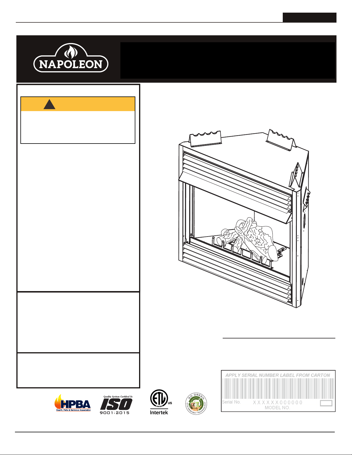
ADD ____ ILLUSTRATED
ADD PRODUCT IMAGE
CERTIFICATION
LOGO
SAFETY INFORMATION
- Do not store or use gasoline or other
fl ammable vapors and liquids in the vicinity of
this or any other appliance.
- WHAT TO DO IF YOU SMELL GAS:
• Do not try to light any appliance.
• Do not touch any electrical switch; do not
use any phone in your building.
• Immediately call your gas supplier from a
neighbour’s phone. Follow the gas
supplier’s instructions.
• If you cannot reach your gas supplier, call
the fi re department.
- Installation and service must be
performed by a qualifi ed installer, service
agency, or the supplier.
- This is an unvented gas-fi red heater that
uses air (oxygen) from the room in which
it is installed. Provisions for adequate
combustion and ventilation air must be
provided. Refer to section “combustion
and ventilation air provisions”.
This appliance may be installed in an aftermarket,
permanently located, manufactured home (USA
only) or mobile home, where not prohibited by
local codes.
This appliance is only for use with the type of gas
indicated on the rating plate. This appliance is
not convertible for use with other gases, unless
a certifi ed kit is used.
FIRE OR EXPLOSION HAZARD
Failure to follow safety warnings exactly
could result in serious injury, death, or
property damage.
WARNING
!
ENGLISH
$10.00
FOR INDOOR USE ONLY
IF INSTALLATION + OPERATION, ADD SERIAL
NUMBER LABEL HERE
IF SEPARATE MANUALS, ADD “PLACE
BARCODE LABEL ON THE OWNER’S MANUAL”
GVF42-1P
GVF42-1N
INSTALLATION AND
OPERATION MANUAL
Grandville™ Vent Free Series
CERTIFIED TO THE AMERICAN NATIONAL STANDARDS:
ANSI Z21.11.2, VOLUME II FOR UNVENTED ROOM HEATERS.
W415-0379 / G / 08.23.18

• This appliance is hot when operated and
can cause severe burns if contacted.
• Any changes or alterations to this
appliance or its controls can be
dangerous and is prohibited.
• Do not operate appliance before reading and
understanding operating instructions. Failure
to operate appliance according to operating
instructions could cause fire or injury.
• Ensure the glass door is opened or removed
when lighting the pilot for the first time and
when the gas supply has run out.
• Risk of fi re or asphyxiation do not operate
appliance with fi xed glass removed and never
obstruct the front opening of the appliance.
• Objects placed in front of the appliance must
be kept a minimum of 4 feet (1.22m) from the
front face of the appliance.
• Do not connect 110 volts to the control valve,
with the exception of models; GSST8 and GT8.
• Risk of burns. The appliance should be turned off and cooled before servicing.
• Do not install damaged, incomplete or substitute components.
• Risk of cuts and abrasions. Wear protective gloves, protective footwear, and safety glasses during
installation. Sheet metal edges may be sharp.
• Do not burn wood or other materials in this appliance.
• Provide adequate ventilation and combustion air. Provide adequate accessibility clearance for servicing
and operating the appliance. Never obstruct the front opening of the appliance.
• The appliance area must be kept clear and free from combustible materials, gasoline and other
fl ammable vapors and liquids.
• High pressure will damage valve. Disconnect gas supply piping before pressure testing gas line at
test pressures above 1/2 psig. Close the manual shut-off valve before pressure testing gas line at test
pressures equal to or less than 1/2 psig (35mb).
• The appliance must not be operated at temperatures below freezing (32°F / 0°C). Allow the appliance
to warm to above freezing prior to operation, with the exception of models; GSS36, GSS42; these
appliances are suitable for 0°F / -18°C.
• Children and adults should be alerted to hazards of high surface temperature and should stay
away to avoid burns or clothing ignition.
• Young children should be carefully supervised when they are in the same room as the
appliance. Toddlers, young children and others may be susceptible to accidental contact
burns. A physical barrier is recommended if there are at risk individuals in the house. To
restrict access to an appliance or stove, install an adjustable safety gate to keep toddlers,
young children and other at risk individuals out of the room and away from hot surfaces.
• Clothing or other fl ammable material should not be placed on or near the appliance.
• Due to high temperatures, the appliance should be located out of traffi c and away from
furniture and draperies.
• Furniture or other objects must be kept a minimum of 4 feet (1.22m) away from the front of the appliance.
• Ensure you have incorporated adequate safety measure to protect infants/toddlers from touching hot
surfaces.
• Even after the appliance is off, it will remain hot for an extended period of time.
• Check with your local hearth specialty dealer for safety screens and hearth guards to protect children
from hot surfaces. These screens and guards must be fastened to the floor.
• Any safety screen, guard or barrier removed for servicing the appliance, must be replaced prior
to operating the appliance.
• It is imperative that the control compartments, burners and circulating blower and its passageway in the
appliance and venting system are kept clean. The appliance and its venting system should be inspected
before use and at least annually by a qualified service person. More frequent cleaning may be required
due to excessive lint from carpeting, bedding material, etc. The appliance area must be kept clear and
free from combustible materials, gasoline and other flammable vapors and liquids.
• If the appliance shuts off, do not re-light until you provide fresh air. If appliance keeps shutting off, have it
serviced. Keep burner and control compartment clean.
• Under no circumstances should this appliance be modifi ed.
LA VITRE CHAUDE CAUSERA
DES BRÛLURES.
NE PAS TOUCHER LA VITRE
AVANT QU’ELLE AIT REFROIDI.
NE JAMAIS LAISSER LES
ENFANTS TOUCHER LA VITRE.
HOT GLASS WILL CAUSE
BURNS.
DO NOT TOUCH GLASS UNTIL
COOLED.
NEVER ALLOW CHILDREN TO
TOUCH GLASS.
!
DANGER
!
AVERTISSEMENT
A barrier designed to reduce the risk of burns from the
hot viewing glass is provided with this appliance and
shall be installed for the protection of children and other
at-risk individuals.
Une barriére conçu à réduire le risque de brûlures
causées par le verre chaud est fourni avec l’appareil et
sera installé pour la protection des enfants et d’autres
personnes à risque.
3.1B
!
WARNING
!
WARNING
• Do not allow wind or fans to blow directly into the appliance. Avoid any drafts that alter burner flame
patterns.
• Do not use a blower insert, heat exchanger insert or other accessory not approved for use with this
appliance.
• This appliance must not be connected to a chimney flue pipe serving a separate solid fuel burning
appliance.
• Do not use this appliance if any part has been under water. Immediately call a qualified service technician
to inspect the appliance and to replace any part of the control system and any gas control which has
been under water.
• Do not operate the appliance with the glass door removed, cracked or broken. Replacement of the glass
should be done by a licensed or qualified service person, if equipped.
• Do not strike or slam shut the appliance glass door, if equipped.
• Only doors / optional fronts certified with the appliance are to be installed on the appliance.
• Keep the packaging material out of reach of children and dispose of the material in a safe manner. As
with all plastic bags, these are not toys and should be kept away from children and infants.
• Carbon or soot should not occur in a vent free appliance as it can distribute into the living area of your
home. If you notice any signs of carbon or soot, immediately turn off your appliance and arrange to have
it serviced by a qualified technician before operating it again.
• If equipped, the screen must be in place (closed) when the appliance is in operation.
• When equipped with pressure relief doors, they must be kept closed while the appliance is operating
to prevent exhaust fumes containing carbon monoxide, from entering into the home. Temperatures of
the exhaust escaping through these openings can also cause the surrounding combustible materials to
overheat and catch fire.
• Carbon monoxide poisoning may lead to death; early signs of carbon monoxide poisoning resemble
the flu, with headache, dizziness and/or nausea. If you have these signs, the heater may not be working
properly. Get fresh air at once! Have heater serviced. Some people; pregnant women, persons with heart
or lung disease, anemia, those under the influence of alcohol, those at high altitudes are more affected by
carbon monoxide than others. Failure to keep the primary air opening(s) of the burner(s) clean may result
in sooting and property damage.
• As with any combustion appliance, we recommend having your appliance regularly inspected and
serviced as well as having a Carbon Monoxide Detector installed in the same area to defend you and
your family against Carbon Monoxide.(Not applicable for outdoor appliances).
• Ensure clearances to combustibles are maintained when building a mantel or shelves above the
appliance. Elevated temperatures on the wall or in the air above the appliance can cause melting,
discolouration or damage to decorations, a T.V. or other electronic components.
• For appliances equipped with a safety barrier; the barrier is designed to reduce the risk of
burns from the hot viewing glass is provided with this appliance and shall be installed. If the
barrier becomes damaged, the barrier shall be replaced with the manufacturer’s barrier for this
appliance.
• Installation and repair should be done by a qualified service person. The appliance should be
inspected before use and at least annually by a professional service person. More frequent
cleaning may be required due to excessive lint from carpeting, bedding material, etc. It
is imperative that control compartments, burners and circulating air passageways of the
appliance be kept clean.
• For outdoor products only: this appliance must not be installed indoors or within any structure that
prevents or inhibits the exhaust gases from dissipating in the outside atmosphere.
• If applicable, the millivolt version of this appliance uses and requires a fast acting thermocouple. Replace
only with a fast acting thermocouple supplied by Wolf Steel Ltd.
!
WARNING
!
Disconnect the appliance main gas valve/control
from the supply piping when pressure testing that
system at pressures in excess of 1/2 psi (3.5 kPa).
Isolate the appliance with it’s shut off valve during
any pressure testing of the supply piping at
pressures equal to or less than 1/2 psi (3.5 kPa).
FIRE RISK HAZARD / DELAYED IGNITION
High supply pressure will damage the valve / controls.
W415-0379 / G / 08.23.18
EN
safety information
2

• This appliance is hot when operated and
can cause severe burns if contacted.
• Any changes or alterations to this
appliance or its controls can be
dangerous and is prohibited.
• Do not operate appliance before reading and
understanding operating instructions. Failure
to operate appliance according to operating
instructions could cause fire or injury.
• Ensure the glass door is opened or removed
when lighting the pilot for the first time and
when the gas supply has run out.
• Risk of fire or asphyxiation do not operate
appliance with fixed glass removed and never
obstruct the front opening of the appliance.
• Objects placed in front of the appliance must
be kept a minimum of 4 feet (1.22m) from the
front face of the appliance.
• Do not connect 110 volts to the control valve,
with the exception of models; GSST8 and GT8.
• Risk of burns. The appliance should be turned off and cooled before servicing.
• Do not install damaged, incomplete or substitute components.
• Risk of cuts and abrasions. Wear protective gloves, protective footwear, and safety glasses during
installation. Sheet metal edges may be sharp.
• Do not burn wood or other materials in this appliance.
• Provide adequate ventilation and combustion air. Provide adequate accessibility clearance for servicing
and operating the appliance. Never obstruct the front opening of the appliance.
• The appliance area must be kept clear and free from combustible materials, gasoline and other
flammable vapors and liquids.
• High pressure will damage valve. Disconnect gas supply piping before pressure testing gas line at
test pressures above 1/2 psig. Close the manual shut-off valve before pressure testing gas line at test
pressures equal to or less than 1/2 psig (35mb).
• The appliance must not be operated at temperatures below freezing (32°F / 0°C). Allow the appliance
to warm to above freezing prior to operation, with the exception of models; GSS36, GSS42; these
appliances are suitable for 0°F / -18°C.
• Children and adults should be alerted to hazards of high surface temperature and should stay
away to avoid burns or clothing ignition.
• Young children should be carefully supervised when they are in the same room as the
appliance. Toddlers, young children and others may be susceptible to accidental contact
burns. A physical barrier is recommended if there are at risk individuals in the house. To
restrict access to an appliance or stove, install an adjustable safety gate to keep toddlers,
young children and other at risk individuals out of the room and away from hot surfaces.
• Clothing or other flammable material should not be placed on or near the appliance.
• Due to high temperatures, the appliance should be located out of traffic and away from
furniture and draperies.
• Furniture or other objects must be kept a minimum of 4 feet (1.22m) away from the front of the appliance.
• Ensure you have incorporated adequate safety measure to protect infants/toddlers from touching hot
surfaces.
• Even after the appliance is off, it will remain hot for an extended period of time.
• Check with your local hearth specialty dealer for safety screens and hearth guards to protect children
from hot surfaces. These screens and guards must be fastened to the floor.
• Any safety screen, guard or barrier removed for servicing the appliance, must be replaced prior
to operating the appliance.
• It is imperative that the control compartments, burners and circulating blower and its passageway in the
appliance and venting system are kept clean. The appliance and its venting system should be inspected
before use and at least annually by a qualified service person. More frequent cleaning may be required
due to excessive lint from carpeting, bedding material, etc. The appliance area must be kept clear and
free from combustible materials, gasoline and other flammable vapors and liquids.
• If the appliance shuts off, do not re-light until you provide fresh air. If appliance keeps shutting off, have it
serviced. Keep burner and control compartment clean.
• Under no circumstances should this appliance be modified.
LA VITRE CHAUDE CAUSERA
DES BRÛLURES.
NE PAS TOUCHER LA VITRE
AVANT QU’ELLE AIT REFROIDI.
NE JAMAIS LAISSER LES
ENFANTS TOUCHER LA VITRE.
HOT GLASS WILL CAUSE
BURNS.
DO NOT TOUCH GLASS UNTIL
COOLED.
NEVER ALLOW CHILDREN TO
TOUCH GLASS.
!
DANGER
!
AVERTISSEMENT
A barrier designed to reduce the risk of burns from the
hot viewing glass is provided with this appliance and
shall be installed for the protection of children and other
at-risk individuals.
Une barriére conçu à réduire le risque de brûlures
causées par le verre chaud est fourni avec l’appareil et
sera installé pour la protection des enfants et d’autres
personnes à risque.
3.1B
!
WARNING
!
WARNING
• Do not allow wind or fans to blow directly into the appliance. Avoid any drafts that alter burner fl ame
patterns.
• Do not use a blower insert, heat exchanger insert or other accessory not approved for use with this
appliance.
• This appliance must not be connected to a chimney fl ue pipe serving a separate solid fuel burning
appliance.
• Do not use this appliance if any part has been under water. Immediately call a qualifi ed service technician
to inspect the appliance and to replace any part of the control system and any gas control which has
been under water.
• Do not operate the appliance with the glass door removed, cracked or broken. Replacement of the glass
should be done by a licensed or qualified service person, if equipped.
• Do not strike or slam shut the appliance glass door, if equipped.
• Only doors / optional fronts certifi ed with the appliance are to be installed on the appliance.
• Keep the packaging material out of reach of children and dispose of the material in a safe manner. As
with all plastic bags, these are not toys and should be kept away from children and infants.
• Carbon or soot should not occur in a vent free appliance as it can distribute into the living area of your
home. If you notice any signs of carbon or soot, immediately turn off your appliance and arrange to have
it serviced by a qualified technician before operating it again.
• If equipped, the screen must be in place (closed) when the appliance is in operation.
• When equipped with pressure relief doors, they must be kept closed while the appliance is operating
to prevent exhaust fumes containing carbon monoxide, from entering into the home. Temperatures of
the exhaust escaping through these openings can also cause the surrounding combustible materials to
overheat and catch fire.
• Carbon monoxide poisoning may lead to death; early signs of carbon monoxide poisoning resemble
the flu, with headache, dizziness and/or nausea. If you have these signs, the heater may not be working
properly. Get fresh air at once! Have heater serviced. Some people; pregnant women, persons with heart
or lung disease, anemia, those under the influence of alcohol, those at high altitudes are more affected by
carbon monoxide than others. Failure to keep the primary air opening(s) of the burner(s) clean may result
in sooting and property damage.
• As with any combustion appliance, we recommend having your appliance regularly inspected and
serviced as well as having a Carbon Monoxide Detector installed in the same area to defend you and
your family against Carbon Monoxide.(Not applicable for outdoor appliances).
• Ensure clearances to combustibles are maintained when building a mantel or shelves above the
appliance. Elevated temperatures on the wall or in the air above the appliance can cause melting,
discolouration or damage to decorations, a T.V. or other electronic components.
• For appliances equipped with a safety barrier; the barrier is designed to reduce the risk of
burns from the hot viewing glass is provided with this appliance and shall be installed. If the
barrier becomes damaged, the barrier shall be replaced with the manufacturer’s barrier for this
appliance.
• Installation and repair should be done by a qualifi ed service person. The appliance should be
inspected before use and at least annually by a professional service person. More frequent
cleaning may be required due to excessive lint from carpeting, bedding material, etc. It
is imperative that control compartments, burners and circulating air passageways of the
appliance be kept clean.
• For outdoor products only: this appliance must not be installed indoors or within any structure that
prevents or inhibits the exhaust gases from dissipating in the outside atmosphere.
• If applicable, the millivolt version of this appliance uses and requires a fast acting thermocouple. Replace
only with a fast acting thermocouple supplied by Wolf Steel Ltd.
!
WARNING
!
Disconnect the appliance main gas valve/control
from the supply piping when pressure testing that
system at pressures in excess of 1/2 psi (3.5 kPa).
Isolate the appliance with it’s shut off valve during
any pressure testing of the supply piping at
pressures equal to or less than 1/2 psi (3.5 kPa).
FIRE RISK HAZARD / DELAYED IGNITION
High supply pressure will damage the valve / controls.
W415-0379 / G / 08.23.18
EN
safety information
3

1.0 general information 5
1.1 rates and efficiencies 5
1.2 installation overview 6
1.3 rating plate information 8
1.4 mobile home installation 8
1.5 dimensions 9
2.0 installation 10
2.1 gas installation 11
2.2 optional wall switch / thermostat 11
3.0 framing 12
3.1 minimum clearance to combustibles 13
3.2 minimum clearances to combustible enclosures 14
3.3 alcove installation 15
3.4 minimum mantel clearances 15
3.5 nailing tab installation 16
4.0 finishing 17
4.1 grate installation 17
4.2 log placement 17
4.3 glowing embers 19
4.4 charcoal embers 19
4.5 vermiculite 19
4.6 charcoal lumps 19
4.7 hood 20
4.8 L42 louvre installation 21
4.9 logo placement 21
5.0 optional blower installation 22
6.0 operation 24
7.0 adjustment 25
7.1 venturi adjustment 25
7.2 flame characteristics 25
8.0 maintenance 26
8.1 oxygen depletion sensor pilot cleaning 26
8.2 care of plated parts 27
9.0 replacement parts 28
9.1 GVF42-1 overview 29
10.0 accessories 30
11.0 troubleshooting 31
12.0 warranty 33
The information throughout this manual is believed to be correct at the time of printing. Wolf Steel
Ltd. reserves the right to change or modify any information within this manual at any time without
notice. Changes, other than editorial are denoted by a vertical line in the margin.
note:
W415-0379 / G / 08.23.18
EN
table of contents
4
Installer, please fill out the following information:
Customer: ______________________________________________________________
Address: ______________________________________________________________
Date of Installation: ______________________________________________________________
Location of Appliance: ______________________________________________________________
Installer: ______________________________________________________________
Dealer/Distributor Contact Number: ______________________________________________________________
Serial #: ______________________________________________________________
Model:
Natural Gas: Propane:
GVF42-1N
GVF42-1P
1.0 general information
When the appliance is installed at elevations above 2,000ft, and in the absence of specific recommendations from the local
authority having jurisdiction, the certified high altitude input rating shall be reduced at the rate of 4% for each additional
1,000ft.
This appliance is only for use with the type of gas indicated on the rating plate. For rating plate information, see “rating plate
information” section. This appliance is not convertible for use with other gases, unless a certified kit is used.
NO EXTERNAL ELECTRICITY (110 VOLTS OR 24 VOLTS) IS REQUIRED FOR THE GAS SYSTEM OPERATION.
Expansion / contraction noises during heating up and cooling down cycles are normal and to be expected.
This appliance is equipped with a pilot light safety system referred to as an oxygen depletion sensor and is designed to
turn off the appliance if not enough fresh air is available.
Use only accessories designed for and listed with your specific appliance.
Not designed for use with a glass door. Screens must be closed when appliance is in operation.
This appliance is a decorative product. It is not a source of heat and not intended to burn solid fuel.
1.1 rates and efficiencies
For your satisfaction, all burner assemblies have been test-fired to assure their operations and quality.
NG P
Altitude (FT) 0-2,000 0-2,000
Max. Input (BTU/HR) 30,000 30,000
Max. Output (BTU/HR) 99.9% 99.9%
Efficiency (w/the fan on) 99.9% 99.9%
Min. Inlet Gas Supply Pressure 4.5" Water Column 11" Water Column
Max. Inlet Gas Supply Pressure 7" Water Column 13" Water Column
Manifold Pressure (Under Flow Conditions) 3.5" Water Column 10" Water Column
W415-0379 / G / 08.23.18
EN
general information
5
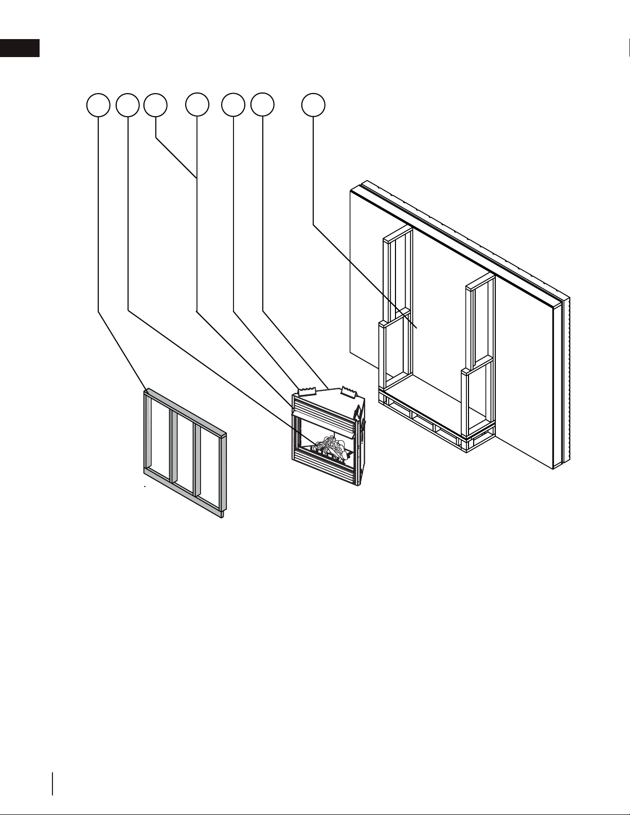
1.2 installation overview
Recommended installation steps:
1. Place the appliance in its final position.
2. Install gas lines (see “gas installation” section).
3. Install framing (see “framing” section).
4. Install nailing tabs (see “nailing tab installation” section).
5. Install optional blower (see “optional blower installation” section).
6. Test appliance.
7. Complete finishing (see “finishing” section).
3
4
5
6
2
1
7
W415-0379 / G / 08.23.18
EN
general information
6

!
WARNING
• Carbon monoxide poisoning may lead to death. Early signs of poisoning resemble the flu, with headache,
dizziness, and/or nausea. If you have these signs, the heater may not be working properly. Get fresh air at once!
Have heater serviced. Some people - pregnant women, people with heart or lung disease, people with anemia,
those under the influence of alcohol, those at high altitudes - are more effected by carbon monoxide than
others.
• It is recommended that people with respiratory problems not use vent free appliances.
• The appliance is only for use with the type of gas indicated on the rating plate. This appliance is not convertible
for use with other gases.
• Objects placed in front of the heater should be kept a minimum of 48” (121.9cm) from the front face of the
appliance.
• Use only Wolf Steel approved optional accessories and replacement parts with this appliance. Using non-listed
accessories and replacement parts (i.e. blowers, louvres, trims, gas components, vent components, etc.) could
result in a safety hazard and will void the limited lifetime warranty.
• Not designed for use with a glass door. Screen must be closed when appliance is in operation.
• This appliance must not be installed in a bedroom or bathroom.
• This product must be installed by a licensed plumber or gas fitter when installed within the commonwealth of
Massachusetts.
4.2
THIS GAS APPLIANCE SHOULD BE INSTALLED AND SERVICED BY A QUALIFIED INSTALLER to
conform with local codes. Installation practices vary from region to region and it is important to know the
specifi cs that apply to your area, for example in Massachusetts State:
•
This product must be installed by a licensed plumber or gas fi tter when installed within the commonwealth of
Massachusetts.
• The appliance off valve must be a “T” handle gas cock.
• The fl exible connector must not be longer than 36” (91.4cm).
• A Carbon Monoxide detector is required in all rooms containing gas fi red appliances.
• The appliance is not approved for installation in a bedroom or bathroom unless the unit is a direct vent
sealed combustion product.
• Un-vented room appliances shall be installed in accordance with 527 CMR 30.00 and 248 CMR 3.00
through 7.00.
• Sellers of un-vented propane or natural gas-fi red space / room appliances shall provide to each purchaser a
copy of 527 CMR 30.00 upon the sale of the appliance from http://www.napoleonfi replaces.com/Webshare/
installation_manuals/mass_requirements.pdf
In absence of local codes, install the appliance to the current National Fuel Gas Code, ANSI Z223.1 Installation
Code which can be obtained from:
American National Standards Institute Inc. or National Fire Protection Association Inc.
1430 Broadway Batterymarch Park
New York, NY 10018 Quincy, MA 02269
The appliance and its individual shutoff valve must be disconnected from the gas supply piping system during
any pressure testing of that system at test pressures in excess of 1/2 psig (35 mb). The appliance must be
isolated from the gas supply piping system by closing its individual manual shutoff valve during any pressure
testing of the gas supply piping system at test pressures equal to or less than 1/2 psig (35 mb). When installed
with a blower or fan, the junction box must be electrically connected and grounded in accordance with local
codes. In the absence of local codes, use the current ANSI / NFPA 70 National Electric Code. In the case
where the blower is equipped with a power cord it must be connected into a properly grounded receptacle. The
grounding prong must not be removed from the cord plug.
As long as the required clearance to combustibles is
maintained, the most desirable and beneficial location for
the appliance is in the center of a building, thereby allowing
the most efficient use of the heat created. The location of
windows, doors and the traffic flow in the room where the
appliance is to be located should be considered.
If the appliance is installed directly on carpeting, vinyl tile
or other combustible material other than wood flooring,
the appliance shall be installed on a metal or wood panel
extending the full width and depth.
Air shortage caused by an inadequate air supply, improper log positions, the addition of foreign or unapproved
materials or the failure to properly maintain the appliance, may result in incomplete combustion of the fuel.
Incomplete combustion results in soot being deposited inside the firebox as well as surfaces outside the
appliance. If any soot deposits are observed, shut off the appliance immediately and arrange for it to be serviced
by a qualified technician.
We suggest that our gas
hearth products be installed
and serviced by professionals
who are certied in the U.S.
by the National Fireplace
Institute
®
(NFI) as NFI Gas
Specialists
www.ncertied.org
This does not apply to stoves.
note:
W415-0379 / G / 08.23.18
EN
general information
7
4.2
THIS GAS APPLIANCE SHOULD BE INSTALLED AND SERVICED BY A QUALIFIED INSTALLER to
conform with local codes. Installation practices vary from region to region and it is important to know the
specifics that apply to your area, for example in Massachusetts State:
• This product must be installed by a licensed plumber or gas fitter when installed within the commonwealth of
Massachusetts.
• The appliance off valve must be a “T” handle gas cock.
• The flexible connector must not be longer than 36” (91.4cm).
• A Carbon Monoxide detector is required in all rooms containing gas fired appliances.
• The appliance is not approved for installation in a bedroom or bathroom unless the unit is a direct vent
sealed combustion product.
• Un-vented room appliances shall be installed in accordance with 527 CMR 30.00 and 248 CMR 3.00
through 7.00.
• Sellers of un-vented propane or natural gas-fired space / room appliances shall provide to each purchaser a
copy of 527 CMR 30.00 upon the sale of the appliance from http://www.napoleonfi replaces.com/Webshare/
installation_manuals/mass_requirements.pdf
In absence of local codes, install the appliance to the current National Fuel Gas Code, ANSI Z223.1 Installation
Code which can be obtained from:
American National Standards Institute Inc. or National Fire Protection Association Inc.
1430 Broadway Batterymarch Park
New York, NY 10018 Quincy, MA 02269
The appliance and its individual shutoff valve must be disconnected from the gas supply piping system during
any pressure testing of that system at test pressures in excess of 1/2 psig (35 mb). The appliance must be
isolated from the gas supply piping system by closing its individual manual shutoff valve during any pressure
testing of the gas supply piping system at test pressures equal to or less than 1/2 psig (35 mb). When installed
with a blower or fan, the junction box must be electrically connected and grounded in accordance with local
codes. In the absence of local codes, use the current ANSI / NFPA 70 National Electric Code. In the case
where the blower is equipped with a power cord it must be connected into a properly grounded receptacle. The
grounding prong must not be removed from the cord plug.
As long as the required clearance to combustibles is
maintained, the most desirable and benefi cial location for
the appliance is in the center of a building, thereby allowing
the most effi cient use of the heat created. The location of
windows, doors and the traffi c fl ow in the room where the
appliance is to be located should be considered.
If the appliance is installed directly on carpeting, vinyl tile
or other combustible material other than wood fl ooring,
the appliance shall be installed on a metal or wood panel
extending the full width and depth.
Air shortage caused by an inadequate air supply, improper log positions, the addition of foreign or unapproved
materials or the failure to properly maintain the appliance, may result in incomplete combustion of the fuel.
Incomplete combustion results in soot being deposited inside the fi rebox as well as surfaces outside the
appliance. If any soot deposits are observed, shut off the appliance immediately and arrange for it to be serviced
by a qualifi ed technician.
We suggest that our gas
hearth products be installed
and serviced by professionals
who are certied in the U.S.
by the National Fireplace
Institute
®
(NFI) as NFI Gas
Specialists
www.ncertied.org
This does not apply to stoves.
note:
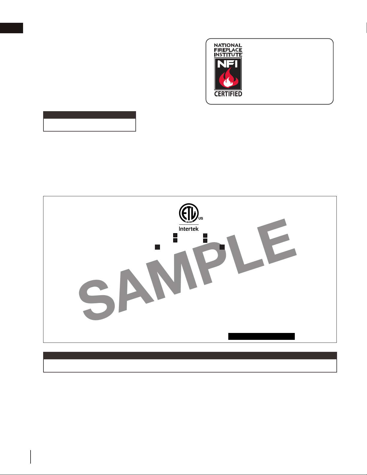
1.3 rating plate information
This illustration is for reference only. Refer to the rating plate on the appliance for accurate information.
CERTIFIED UNDER: ANSI Z21.11.2a-2008 VOLUME II, UNVENTED ROOM HEATER
W385-0248 / H
SERIAL NUMBER: G/CVF42
WOLF STEEL LTD.
24 NAPOLEON ROAD, BARRIE, ON, L4M 0G8 CANADA
THIS APPLIANCE MAY BE INSTALLED IN AN AFTERMARKET,
PERMANENTLY LOCATED, MANUFACTURED (MOBILE) HOME, WHERE
NOT PROHIBITED BY LOCAL CODES. THIS APPLIANCE IS ONLY FOR USE
WITH THE TYPE OF GAS INDICATED ON THE RATING PLATE. THIS
APPLIANCE IS NOT CONVERTIBLE FOR USE WITH OTHER GASES.
THIS IS A GAS-FIRED UNVENTED ROOM HEATER THAT REQUIRES
ADEQUATE COMBUSTION AND VENTILATION AIR. THIS APPLIANCE
IS NOT APPROVED FOR BEDROOM, BATHROOM AND BED-SITTING
ROOM INSTALLATION.
GVF42-N / CVF42-N MODEL GVF42-P / CVF42-P
**0-2000FT (0-610m) ALTITUDE 0-2000FT (0-610m)**
30,000 BTU/h INPUT 30,000 BTU/h
22,000 BTU/h REDUCED INPUT 22,000 BTU/h
MANIFOLD PRESSURE: 3.5" WATER COLUMN MANIFOLD PRESSURE: 10" WATER COLUMN
MINIMUM SUPPLY PRESSURE: 4.5" WATER COLUMN MINIMUM SUPPLY PRESSURE: 11" WATER COLUMN
MAXIMUM SUPPLY PRESSURE: 7.0" WATER COLUMN MAXIMUM SUPPLY PRESSURE: 13" WATER COLUMN
SIT CONTROL: #820637 SIT CONTROL: #820636
OPERATING PILOT OXYPROTECTOR: #8214 OPERATING PILOT OXYPROTECTOR: #8404
** ABOVE 2,000FT, CONSULT LOCAL AUTHORITY HAVING JURISDICTION
NOT FOR USE WITH SOLID FUEL.
WARNING: APPLIANCE SCREENS MUST BE CLOSED WHILE IN OPERATION. DO NOT ADD ANY MATERIAL TO THE APPLIANCE, WHICH WILL COME IN
CONTACT WITH THE FLAMES, OTHER THAN THAT SUPPLIED BY THE MANUFACTURER WITH THE APPLIANCE. DO NOT USE BLOWER INSERT, HEAT EXCHANGER INSERT, OR OTHER
ACCESSORIES NOT APPROVED FOR USE WITH THIS HEATER. IMPROPER INSTALLATION, ADJUSTMENT, ALTERATION, SERVICE OR MAINTAINANCE CAN CAUSE PROPERTY DAMAGE, PERSONAL
INJURY, OR LOSS OF LIFE. REFER TO THE OWNER'S INFORMATION MANUAL PROVIDED WITH THIS APPLIANCE. INSTALLATION AND SERVICE MUST BE PERFORMED BY A QUALIFIED INSTALLER,
SERVICE AGENCY OR THE GAS SUPPLIER.
MINIMUM CLEARANCE TO COMBUSTIBLE MATERIALS:
TOP / SIDES / BACK / FLOOR 0”
RECESSED DEPTH 22“
MANTEL 2”*
MAXIMUM HORIZONTAL EXTENSION: 2". SEE INSTRUCTION MANUAL FOR GREATER
EXTENSIONS.
ELECTRICAL RATING: 115V 0.82AMP, 60HZ
OPTIONAL FAN KIT: GZ550-KT
9700539 (WSL) 4001657 (NGZ)
4001658 (NAC) 4001659 (WUSA)
MATERIAL: CLASS III A-2, PERMANENT LABEL, 2 MIL MATERIAL, 1 MIL ADHESIVE, 3 MIL TOTAL THICKNESS, COMPUCAL WATERPROOF, NON-WATER SOLUBLE ADHESIVE,
CAPABLE OF WITHSTANDING A MAXIMUM TEMPERATURE OF 175° F (79° C).
MIN. LETTERING FOR "NOT FOR USE WITH SOLID FUEL.", "UN COMBUSTIBLE SOLIDE NE DOIT PAS ETRE UTILISE AVEC CELUI." TO BE 10 POINT ARIAL, BOLD FACE,
UPPER CASE AND 2 POINT LEADING SPACING OR EQUIVALENT.
SILVER LETTERING ON BLACK BACKGROUND
MAX OVERALL DECAL SIZE: 8" x 4”
SERIAL NUMBERS TO BE ASCENDING FROM G/CVF42000001
TITLE: RATING PLATE GVF42 / CVF42
REVISION: H: CORRECTED ADHESIVE TEMP LIMIT || 09.27.16_JK
DWG#: W385-0248
DATE: 10.01.01
H
SAMPLE
The rating plate must remain with the appliance at all times. It must not be removed.
note:
1.4 mobile home installation
Suitable for mobile home installation where the mobile home has been permanently placed on its site. This appli-
ance must not be installed in a bedroom or bathroom.
This appliance may be installed in an aftermarket permanently located, manufactured (mobile) home, where not
prohibited by local codes.
W415-0379 / G / 08.23.18
EN
general information
8
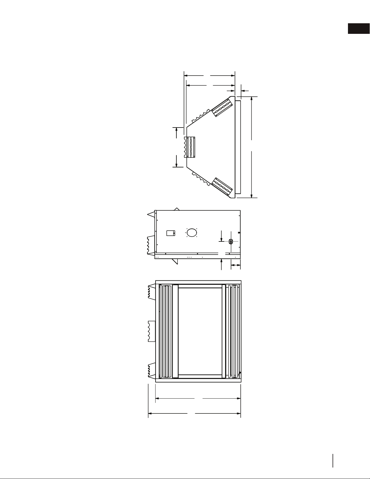
1.5 dimensions
35 ½"
38 ½"
58"
42½"
41"
5½"
3"
16 ½"
20"
22"
42"
2¼"
7
1
/
2
"
27"
18"
12
1
/
4
"
4" DIA.
7" DIA.
front view right side view top view
W415-0379 / G / 08.23.18
EN
general information
9
2.0 installation
The GVF42-1 is rated at 30,000 BTUs per hour for natural gas and 30,000 BTUs for propane, and therefore re-
quires a minimum unconfined space of 1,500 cubic feet.
15.1
This appliance shall not be installed in a confi ned space or unusually tight construction unless provisions are provided for
adequate combustion and ventilation air.
The National Fuel Gas Code, ANSI Z223.1 / NFPA 54 defi nes a confi ned space as a space whose volume is less than 50
cubic feet per 1,000 Btu per hour (4.8 m3 per kw) of the aggregate input rating of all appliances installed in that space
and an unconfi ned space as a space whose volume is not less than 50 cubic feet per 1,000 Btu per hour (4.8 m3 per
kw) of the aggregate input rating of all appliances installed in that space. Rooms communicating directly with the space
in which the appliances are installed, through openings not furnished with doors are considered a part of the unconfi ned
space.
To determine the volume of the room where the appliance is to be installed, multiply the width x the length x the ceiling
height of that room measured in feet. If any adjoining rooms are connected by grilles or openings such as kitchen pass-
throughs, etc., the volume of those rooms may be added to the total.
Multiply the room volume by 1000 and divide this amount by 50 to determine the maximum BTU/hr that the space can
support with adequate combustion and ventilation air.
Add the Btu/hr of all fuel burning appliances located within the space such as gas furnace, gas water appliance, etc.
Do not include direct vent gas appliances which draw their input air from the outdoors and expel their exhaust to the
outdoors.
Unusually tight construction is defined as construction where:
A) Walls and ceilings exposed to the outside atmosphere have a continuous water vapour retarder with a rating of 1
perm (6 x 10-11 kg per pa-sec-m2) or less with openings gasketed or sealed
B) Weather stripping has been added on openable windows and doors
C) Caulking or sealants are applied to areas such as joints around window and door frames, between sole plates and
floors, between wall-ceiling joints, between wall panels, at penetrations for plumbing, electrical, and gas lines, and at
other openings.
An unvented room appliance is recommended for use as a secondary heat source rather than as a primary source. Gas
combustion produces water vapour which could occur at the rate of approximately one ounce of water for every 1,000
BTU/hr of gas input. During the cold weather season, indoor humidity levels tend to be low. Consequently, this water
vapour can enhance the living space. However if a problem should occur:
A) Ensure sufficient combustion and circulation air
B) Use a dehumidifier
C) Do not use the unvented room appliance as a primary heat
source. Without sufficient fresh air for proper operation, poor fuel
combustion can result. Carbon Monoxide is a result of poor fuel
combustion.
If additional fresh air is required, use one of the methods
described in the National Fuel Gas Code, ANSI Z223.1 / NFPA54
or the applicable local code.
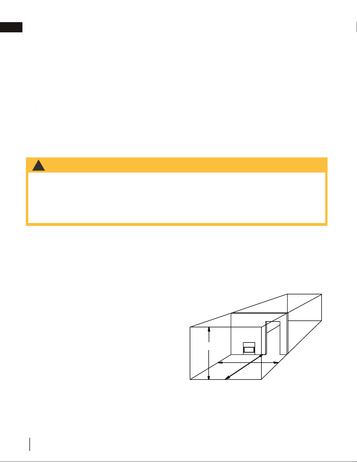
Room Volume = Length x Width x Height
Max BTU/hr = Room Volume x 1000 / 50
If for example:
The length of the rooms is 5 feet (1.5m),
The width of Room 1 is 10 feet (3.1m),
The width of Room 2 is 15 feet (4.6m),
The height of the rooms is 8 feet (2.4m).
Volume of Room 1: 5x10x8 = 400 cubic feet (11.16 cubic meters)
Volume of Room 2: 5x15x8 = 600 cubic feet (16.56 cubic meters)
EXAMPLE 1:
In this example, because there is no door to the adjoining room, the volume of the adjoining room may be added to the
volume of the room with the heater to get a total unconfined space.
The total unconfined space: 400 ft
3
(11.3m
3
)+ 600 ft
3
(17m
3
) = 1000 cubic feet (28.3m
3
).
Maximum BTU/h: [(1000x1000) ÷ 50] = 20,000 BTU/h
EXAMPLE 2:
If in this example a solid door separates Room 1 from Room 2, the volume of Room 2 could not be used. In this case the
maximum BTU/h would be:
Maximum BTU/h: [(400x1000) ÷50] = 8,000 BTU/h
HEIGHT
ROOM 1
ROOM 2
WIDTH
LENGTH
• If the area in which the appliance may be operated is smaller than that defined as an unconfined space or if
the building is of unusually tight construction, provide adequate combustion and ventilation air by one of the
methods described in the National Fuel Gas Code ANSI Z223.1 / NFPA 54, air for combustion and ventilation,
or the applicable local code.
• If the area in which the appliance may be operated does not meet the required volume for indoor combustion
air, combustion and ventilation air shall be provided by one of the methods described in the ANSI Z223.1 /
NFPA 54, the International Fuel Gas Code, or applicable local codes.
!
WARNING
15.1
This appliance shall not be installed in a confined space or unusually tight construction unless provisions are provided for
adequate combustion and ventilation air.
The National Fuel Gas Code, ANSI Z223.1 / NFPA 54 defines a confined space as a space whose volume is less than 50
cubic feet per 1,000 Btu per hour (4.8 m3 per kw) of the aggregate input rating of all appliances installed in that space
and an unconfined space as a space whose volume is not less than 50 cubic feet per 1,000 Btu per hour (4.8 m3 per
kw) of the aggregate input rating of all appliances installed in that space. Rooms communicating directly with the space
in which the appliances are installed, through openings not furnished with doors are considered a part of the unconfined
space.
To determine the volume of the room where the appliance is to be installed, multiply the width x the length x the ceiling
height of that room measured in feet. If any adjoining rooms are connected by grilles or openings such as kitchen pass-
throughs, etc., the volume of those rooms may be added to the total.
Multiply the room volume by 1000 and divide this amount by 50 to determine the maximum BTU/hr that the space can
support with adequate combustion and ventilation air.
Add the Btu/hr of all fuel burning appliances located within the space such as gas furnace, gas water appliance, etc.
Do not include direct vent gas appliances which draw their input air from the outdoors and expel their exhaust to the
outdoors.
Unusually tight construction is defi ned as construction where:
A) Walls and ceilings exposed to the outside atmosphere have a continuous water vapour retarder with a rating of 1
perm (6 x 10-11 kg per pa-sec-m2) or less with openings gasketed or sealed
B) Weather stripping has been added on openable windows and doors
C) Caulking or sealants are applied to areas such as joints around window and door frames, between sole plates and
fl oors, between wall-ceiling joints, between wall panels, at penetrations for plumbing, electrical, and gas lines, and at
other openings.
An unvented room appliance is recommended for use as a secondary heat source rather than as a primary source. Gas
combustion produces water vapour which could occur at the rate of approximately one ounce of water for every 1,000
BTU/hr of gas input. During the cold weather season, indoor humidity levels tend to be low. Consequently, this water
vapour can enhance the living space. However if a problem should occur:
A) Ensure suffi cient combustion and circulation air
B) Use a dehumidifi er
C) Do not use the unvented room appliance as a primary heat
source. Without suffi cient fresh air for proper operation, poor fuel
combustion can result. Carbon Monoxide is a result of poor fuel
combustion.
If additional fresh air is required, use one of the methods
described in the National Fuel Gas Code, ANSI Z223.1 / NFPA54
or the applicable local code.
Room Volume = Length x Width x Height
Max BTU/hr = Room Volume x 1000 / 50
If for example:
The length of the rooms is 5 feet (1.5m),
The width of Room 1 is 10 feet (3.1m),
The width of Room 2 is 15 feet (4.6m),
The height of the rooms is 8 feet (2.4m).
Volume of Room 1: 5x10x8 = 400 cubic feet (11.16 cubic meters)
Volume of Room 2: 5x15x8 = 600 cubic feet (16.56 cubic meters)
EXAMPLE 1:
In this example, because there is no door to the adjoining room, the volume of the adjoining room may be added to the
volume of the room with the heater to get a total unconfined space.
The total unconfined space: 400 ft
3
(11.3m
3
)+ 600 ft
3
(17m
3
) = 1000 cubic feet (28.3m
3
).
Maximum BTU/h: [(1000x1000) ÷ 50] = 20,000 BTU/h
EXAMPLE 2:
If in this example a solid door separates Room 1 from Room 2, the volume of Room 2 could not be used. In this case the
maximum BTU/h would be:
Maximum BTU/h: [(400x1000) ÷50] = 8,000 BTU/h
HEIGHT
ROOM 1
ROOM 2
WIDTH
LENGTH
• If the area in which the appliance may be operated is smaller than that defi ned as an unconfi ned space or if
the building is of unusually tight construction, provide adequate combustion and ventilation air by one of the
methods described in the National Fuel Gas Code ANSI Z223.1 / NFPA 54, air for combustion and ventilation,
or the applicable local code.
• If the area in which the appliance may be operated does not meet the required volume for indoor combustion
air, combustion and ventilation air shall be provided by one of the methods described in the ANSI Z223.1 /
NFPA 54, the International Fuel Gas Code, or applicable local codes.
!
WARNING
W415-0379 / G / 08.23.18
EN
10
15.1
This appliance shall not be installed in a confined space or unusually tight construction unless provisions are provided for
adequate combustion and ventilation air.
The National Fuel Gas Code, ANSI Z223.1 / NFPA 54 defines a confined space as a space whose volume is less than 50
cubic feet per 1,000 Btu per hour (4.8 m3 per kw) of the aggregate input rating of all appliances installed in that space
and an unconfined space as a space whose volume is not less than 50 cubic feet per 1,000 Btu per hour (4.8 m3 per
kw) of the aggregate input rating of all appliances installed in that space. Rooms communicating directly with the space
in which the appliances are installed, through openings not furnished with doors are considered a part of the unconfined
space.
To determine the volume of the room where the appliance is to be installed, multiply the width x the length x the ceiling
height of that room measured in feet. If any adjoining rooms are connected by grilles or openings such as kitchen pass-
throughs, etc., the volume of those rooms may be added to the total.
Multiply the room volume by 1000 and divide this amount by 50 to determine the maximum BTU/hr that the space can
support with adequate combustion and ventilation air.
Add the Btu/hr of all fuel burning appliances located within the space such as gas furnace, gas water appliance, etc.
Do not include direct vent gas appliances which draw their input air from the outdoors and expel their exhaust to the
outdoors.
Unusually tight construction is defined as construction where:
A) Walls and ceilings exposed to the outside atmosphere have a continuous water vapour retarder with a rating of 1
perm (6 x 10-11 kg per pa-sec-m2) or less with openings gasketed or sealed
B) Weather stripping has been added on openable windows and doors
C) Caulking or sealants are applied to areas such as joints around window and door frames, between sole plates and
floors, between wall-ceiling joints, between wall panels, at penetrations for plumbing, electrical, and gas lines, and at
other openings.
An unvented room appliance is recommended for use as a secondary heat source rather than as a primary source. Gas
combustion produces water vapour which could occur at the rate of approximately one ounce of water for every 1,000
BTU/hr of gas input. During the cold weather season, indoor humidity levels tend to be low. Consequently, this water
vapour can enhance the living space. However if a problem should occur:
A) Ensure sufficient combustion and circulation air
B) Use a dehumidifier
C) Do not use the unvented room appliance as a primary heat
source. Without sufficient fresh air for proper operation, poor fuel
combustion can result. Carbon Monoxide is a result of poor fuel
combustion.
If additional fresh air is required, use one of the methods
described in the National Fuel Gas Code, ANSI Z223.1 / NFPA54
or the applicable local code.
Room Volume = Length x Width x Height
Max BTU/hr = Room Volume x 1000 / 50
If for example:
The length of the rooms is 5 feet (1.5m),
The width of Room 1 is 10 feet (3.1m),
The width of Room 2 is 15 feet (4.6m),
The height of the rooms is 8 feet (2.4m).
Volume of Room 1: 5x10x8 = 400 cubic feet (11.16 cubic meters)
Volume of Room 2: 5x15x8 = 600 cubic feet (16.56 cubic meters)
EXAMPLE 1:
In this example, because there is no door to the adjoining room, the volume of the adjoining room may be added to the
volume of the room with the heater to get a total unconfi ned space.
The total unconfi ned space: 400 ft
3
(11.3m
3
)+ 600 ft
3
(17m
3
) = 1000 cubic feet (28.3m
3
).
Maximum BTU/h: [(1000x1000) ÷ 50] = 20,000 BTU/h
EXAMPLE 2:
If in this example a solid door separates Room 1 from Room 2, the volume of Room 2 could not be used. In this case the
maximum BTU/h would be:
Maximum BTU/h: [(400x1000) ÷50] = 8,000 BTU/h
HEIGHT
ROOM 1
ROOM 2
WIDTH
LENGTH
• If the area in which the appliance may be operated is smaller than that defined as an unconfined space or if
the building is of unusually tight construction, provide adequate combustion and ventilation air by one of the
methods described in the National Fuel Gas Code ANSI Z223.1 / NFPA 54, air for combustion and ventilation,
or the applicable local code.
• If the area in which the appliance may be operated does not meet the required volume for indoor combustion
air, combustion and ventilation air shall be provided by one of the methods described in the ANSI Z223.1 /
NFPA 54, the International Fuel Gas Code, or applicable local codes.
!
WARNING
If there are no more fuel burning appliances within this space then the 30,000 BTU/h input of the appliance is suit-
able to be installed. This also assumes that the construction of this space is not unusually tight.
15.1
This appliance shall not be installed in a confined space or unusually tight construction unless provisions are provided for
adequate combustion and ventilation air.
The National Fuel Gas Code, ANSI Z223.1 / NFPA 54 defines a confined space as a space whose volume is less than 50
cubic feet per 1,000 Btu per hour (4.8 m3 per kw) of the aggregate input rating of all appliances installed in that space
and an unconfined space as a space whose volume is not less than 50 cubic feet per 1,000 Btu per hour (4.8 m3 per
kw) of the aggregate input rating of all appliances installed in that space. Rooms communicating directly with the space
in which the appliances are installed, through openings not furnished with doors are considered a part of the unconfined
space.
To determine the volume of the room where the appliance is to be installed, multiply the width x the length x the ceiling
height of that room measured in feet. If any adjoining rooms are connected by grilles or openings such as kitchen pass-
throughs, etc., the volume of those rooms may be added to the total.
Multiply the room volume by 1000 and divide this amount by 50 to determine the maximum BTU/hr that the space can
support with adequate combustion and ventilation air.
Add the Btu/hr of all fuel burning appliances located within the space such as gas furnace, gas water appliance, etc.
Do not include direct vent gas appliances which draw their input air from the outdoors and expel their exhaust to the
outdoors.
Unusually tight construction is defined as construction where:
A) Walls and ceilings exposed to the outside atmosphere have a continuous water vapour retarder with a rating of 1
perm (6 x 10-11 kg per pa-sec-m2) or less with openings gasketed or sealed
B) Weather stripping has been added on openable windows and doors
C) Caulking or sealants are applied to areas such as joints around window and door frames, between sole plates and
floors, between wall-ceiling joints, between wall panels, at penetrations for plumbing, electrical, and gas lines, and at
other openings.
An unvented room appliance is recommended for use as a secondary heat source rather than as a primary source. Gas
combustion produces water vapour which could occur at the rate of approximately one ounce of water for every 1,000
BTU/hr of gas input. During the cold weather season, indoor humidity levels tend to be low. Consequently, this water
vapour can enhance the living space. However if a problem should occur:
A) Ensure sufficient combustion and circulation air
B) Use a dehumidifier
C) Do not use the unvented room appliance as a primary heat
source. Without sufficient fresh air for proper operation, poor fuel
combustion can result. Carbon Monoxide is a result of poor fuel
combustion.
If additional fresh air is required, use one of the methods
described in the National Fuel Gas Code, ANSI Z223.1 / NFPA54
or the applicable local code.
Room Volume = Length x Width x Height
Max BTU/hr = Room Volume x 1000 / 50
If for example:
The length of the rooms is 5 feet (1.5m),
The width of Room 1 is 10 feet (3.1m),
The width of Room 2 is 15 feet (4.6m),
The height of the rooms is 8 feet (2.4m).
Volume of Room 1: 5x10x8 = 400 cubic feet (11.16 cubic meters)
Volume of Room 2: 5x15x8 = 600 cubic feet (16.56 cubic meters)
EXAMPLE 1:
In this example, because there is no door to the adjoining room, the volume of the adjoining room may be added to the
volume of the room with the heater to get a total unconfined space.
The total unconfined space: 400 ft
3
(11.3m
3
)+ 600 ft
3
(17m
3
) = 1000 cubic feet (28.3m
3
).
Maximum BTU/h: [(1000x1000) ÷ 50] = 20,000 BTU/h
EXAMPLE 2:
If in this example a solid door separates Room 1 from Room 2, the volume of Room 2 could not be used. In this case the
maximum BTU/h would be:
Maximum BTU/h: [(400x1000) ÷50] = 8,000 BTU/h
HEIGHT
ROOM 1
ROOM 2
WIDTH
LENGTH
• If the area in which the appliance may be operated is smaller than that defined as an unconfined space or if
the building is of unusually tight construction, provide adequate combustion and ventilation air by one of the
methods described in the National Fuel Gas Code ANSI Z223.1 / NFPA 54, air for combustion and ventilation,
or the applicable local code.
• If the area in which the appliance may be operated does not meet the required volume for indoor combustion
air, combustion and ventilation air shall be provided by one of the methods described in the ANSI Z223.1 /
NFPA 54, the International Fuel Gas Code, or applicable local codes.
!
WARNING
This would be considered a confined space since it can not support the 30,000 BTU/h input of the appliance and
it would be necessary to provide adequate combustion and ventilation air to Room 1.
2.1 gas installation
21.1
!
WARNING
• Risk of fi re, explosion, or asphyxiation. Ensure there are no ignition sources such as sparks or open fl ames.
• Support gas control when attaching gas supply pipe to prevent damaging gas line.
• Always light the pilot whether for the fi rst time or if the gas supply has run out with the glass door opened
or removed. Purging of the gas supply line should be performed by a qualifi ed service technician. Ensure
that a continuous gas fl ow is at the burner before closing the door. Ensure adequate ventilation. For gas and
electrical locations, see “dimensions” section.
• All gas connections must be contained within the appliance when complete (gas fi replaces only).
• High pressure will damage valve. Disconnect gas supply piping before testing gas line at test pressures above
1/2 PSIG.
• Valve settings have been factory set, do not change.
Installation and servicing to be done by a qualifi ed installer.
• Move the appliance into position and secure.
• If equipped with a fl ex connector, the appliance is designed to accept a 1/2” (13mm) gas supply. Without the
connector, it is designed to accept a 3/8” (9.5mm) gas supply. The appliance is equipped with a manual shut
off valve to turn off the gas supply to the appliance.
• Connect the gas supply in accordance to local codes. In the absence of local codes, install to the current
CAN/CSA-B149.1 Installation Code in Canada or to the current National Fuel Gas Code, ANSI Z223.1 / NFPA
54 in the United States.
• When fl exing any gas line, support the gas valve so that the lines are not bent or kinked.
• The gas line fl ex-connector should be installed to provide suffi cient movement for shifting the burner assembly
on its side to aid with servicing components.
• Check for gas leaks by brushing on a soap and water solution. Do not use open fl ame.
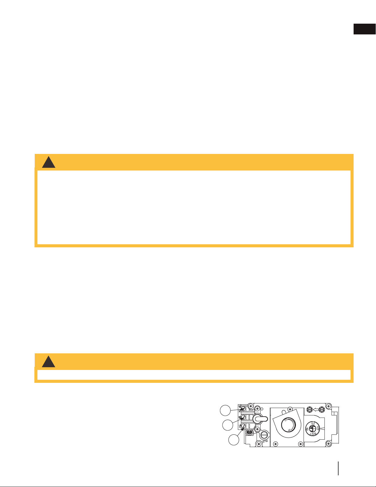
2.2 optional wall switch / thermostat
34.1
!
WARNING
• Do not connect either the wall switch, thermostat or gas valve directly to 110 volt electricity.
For ease of accessibility, an optional remote wall switch or millivolt thermostat may be installed in a convenient
location. Route a 2 strand, solid core millivolt wire from the valve to the wall switch or millivolt thermostat. The
recommended maximum lead length depends on wire size:
WIRE SIZE MAX. LENGTH
14 gauge (1.8mm) 100 feet (30.5m)
16 gauge (1.5mm) 60 feet (18.3m)
18 gauge (1.2mm) 40 feet (12.2m)
Disconnect the existing wires from terminals 1 and 3 (from the
ON/OFF switch) and replace with the leads from the wall switch / millivolt thermostat.
ADD IMAGE
HERE
3
1
2
SIT MILLIVOLT
ROBERT SHAW
P
I
L
O
T
3
1
2
W415-0379 / G / 08.23.18
EN
installation
11
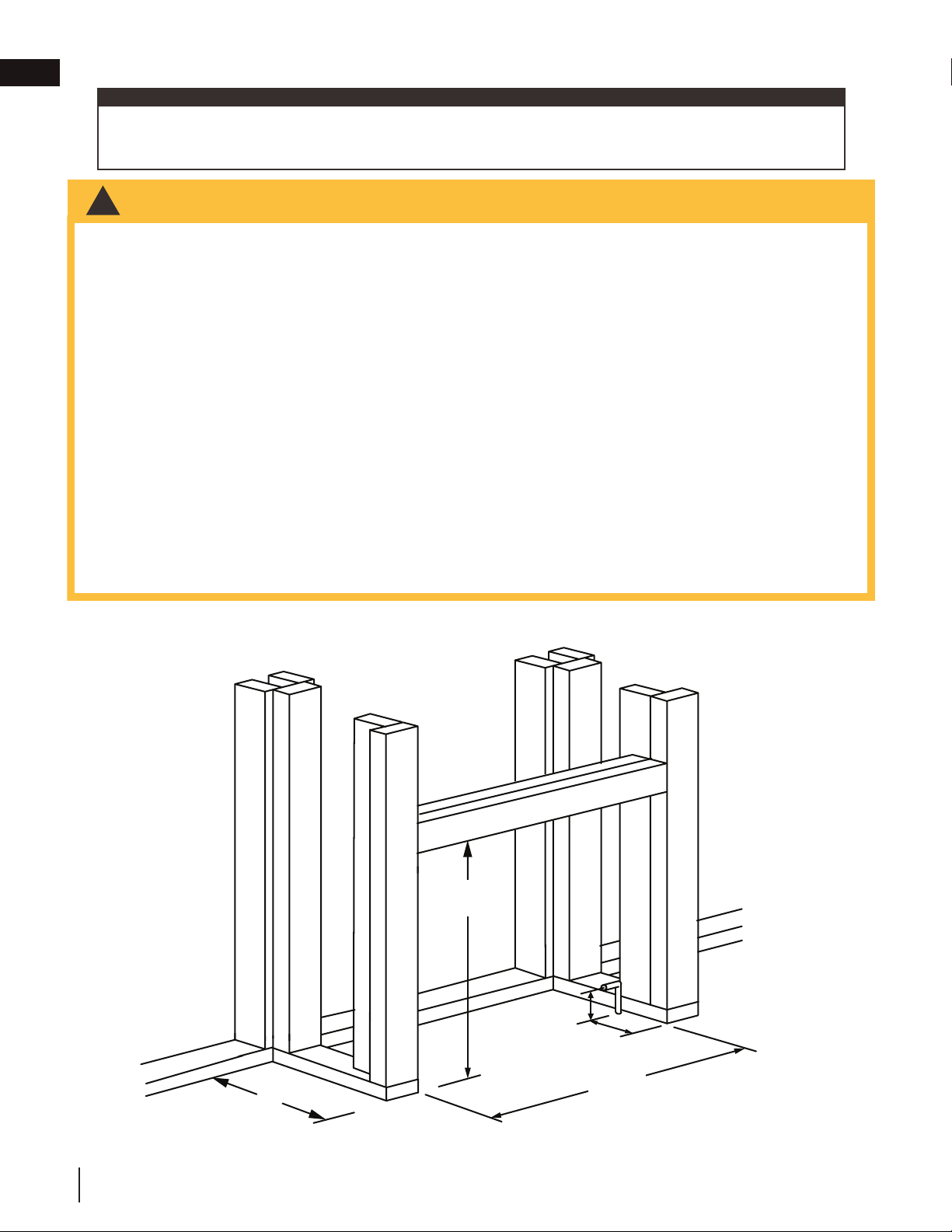
3.0 framing
!
WARNING
• Risk of fi re!
• In order to avoid the possibility of exposed insulation or vapour barrier coming in contact with the appliance
body, it is recommended that the walls of the appliance enclosure be “fi nished” (i.e. drywall / sheetrock),
as you would fi nish any other outside wall of a home. This will ensure that clearance to combustibles is
maintained within the cavity.
• Do not notch the framing around the appliance stand offs. Failure to maintain air space clearance may cause
over heating and fi re. Prevent contact with sagging or loose insulation or framing and other combustible
materials. Block opening into the chase to prevent entry of blown-in insulation. Make sure insulation and
other materials are secured.
• When constructing the enclosure, allow for fi nishing material thickness to maintain clearances. Framing or
fi nishing material closer than the minimums listed must be constructed entirely of non-combustible materials.
Materials consisting entirely of steel, iron, brick, tile, concrete, slate, glass or plasters, or any combination
thereof are suitable. Materials that are reported as passing ASTM E136, standard test method for behaviour
of materials in a vertical tube furnace at 1382ºF (750ºC) and UL763 shall be considered non-combustible
materials.
• Minimum clearance to combusibles must be maintained or a serious fi re hazard could result.
• The appliance requires a minimum enclosure height. Measure from the appliance base.
• If steel stud framing kits with cement board are provided, or specifi ed in the installation instructions, they
must be installed.
• If specifi ed in the installation instruction, fi nishing must be done using a non-combustible board, ceramic tile,
marble, etc. Do NOT use wood or drywall. Any fi re rated drywall is not acceptable.
When using optional fi nishing accessories, the framing dimensions and fi nishing materials may differ from
what is outlined in the section below; refer to the leafl et instructions supplied in the accessory kit for specifi c
framing and fi nishing specifi cations.
44.1
note:
It is best to frame your appliance after it is positioned. Use 2x4’s and frame to local building codes.
42 1/2”
(108cm)
39”
(99.1cm)
3”
(76mm)
5 1/2”
(140mm)
22 1/2”
(57.2cm)
W415-0379 / G / 08.23.18
EN
12
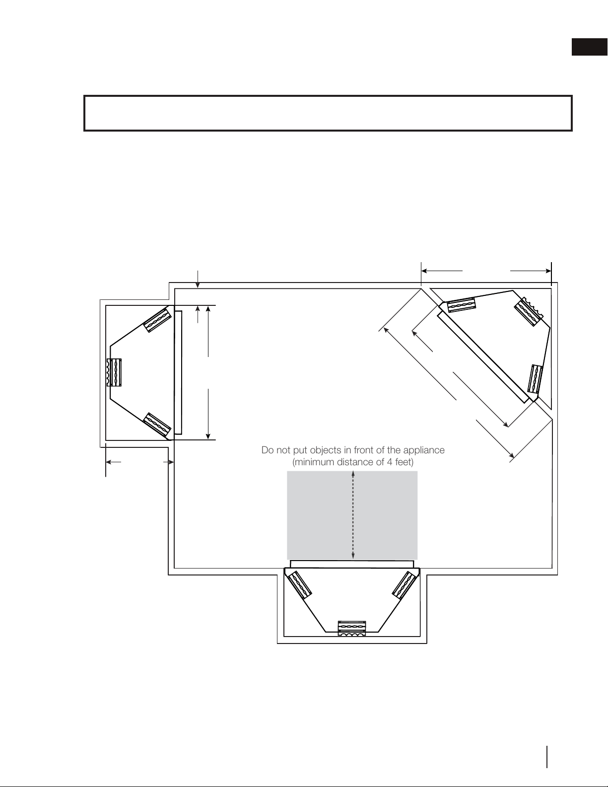
3.1 minimum clearance to combustibles
Minimum clearance to combustible construction from appliance:
Do not put objects in front of the appliance
(minimum distance of 4 feet)
58”
(147.3cm)
42 1/2”
(108cm)
41”
(104.2cm)
6” (15.2cm)
42 1/2”
(108cm)
22 1/2”
(57.2cm)
It is not necessary to install a hearth extension with this appliance system.
When roughing in the appliance, raise the appliance to accommodate for the thickness of the finished floor
materials (i.e. tile, carpeting, hard wood), which if not planned for, will interfere with the opening of the lower
access door and the installation of many decorative flashing accessories.
Raise the appliance up to the height of the finished flooring to ensure control access and accessory installations.
Sides, back, bottom and top of the appliance: 0”
Recessed depth 22” (55.9cm)
W415-0379 / G / 08.23.18
EN
framing
13
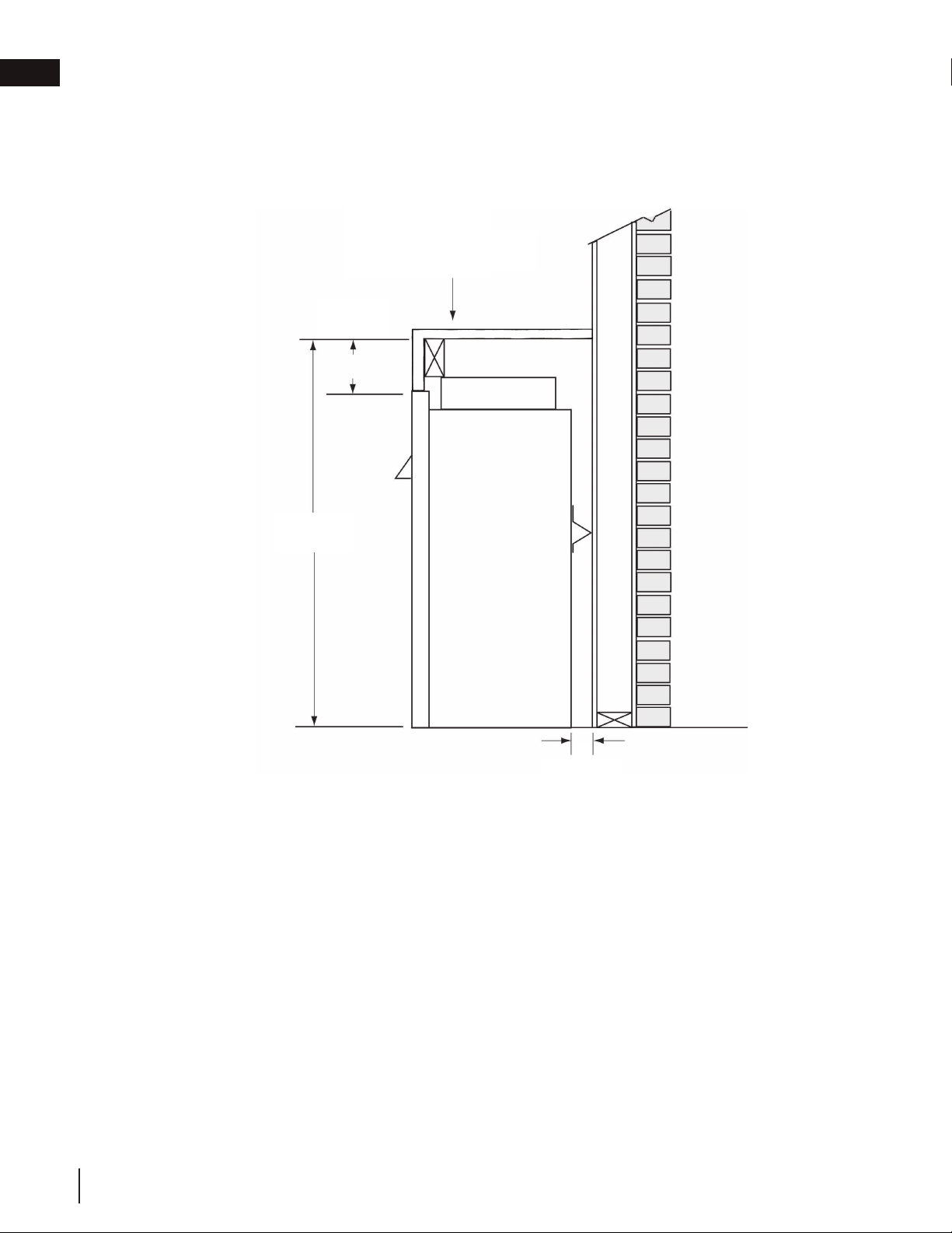
3.2 minimum clearances to combustible enclosures
The appliance requires a minimum enclosure height of 41 1/2” (105.4cm). For temperature requirements, the en-
closure space around and above the appliance must be left unobstructed.
6”
(152mm)
41 1/2”
(105.4cm)
TOP OF COMBUSTIBLE
ENCLOSURE
1” (25mm)
W415-0379 / G / 08.23.18
EN
framing
14
3.3 alcove installation
APPLIANCE
RECESS OR
ALCOVE
AREA
The recesses or alcoves can be made as deep as desired provided the minimum clearances to combustibles are
maintained.
The minimum enclosure volume must be increased by no less than the volume of the recess. This adjustment can
be made by increasing any or all of the height, width and depth of the enclosure.
44.2A
ENCLOSURE
AREA
note:
Recesses or alcoves above the appliance must be made with non-combustible material and regular minimum
clearances, as defined for combustible materials, must still be applied.
3.4 minimum mantel clearances
!
WARNING
45.4
• Risk of fi re. Maintain all specifi ed air space clearances to combustibles. Failure to comply with these instructions
may cause a fi re or cause the appliance to overheat. Ensure all clearances (i.e. back, side, top, vent, mantel,
front, etc.) are clearly maintained.
• When using paint or lacquer to fi nish the mantel, the paint or lacquer must be heat resistant to prevent
discolouration.
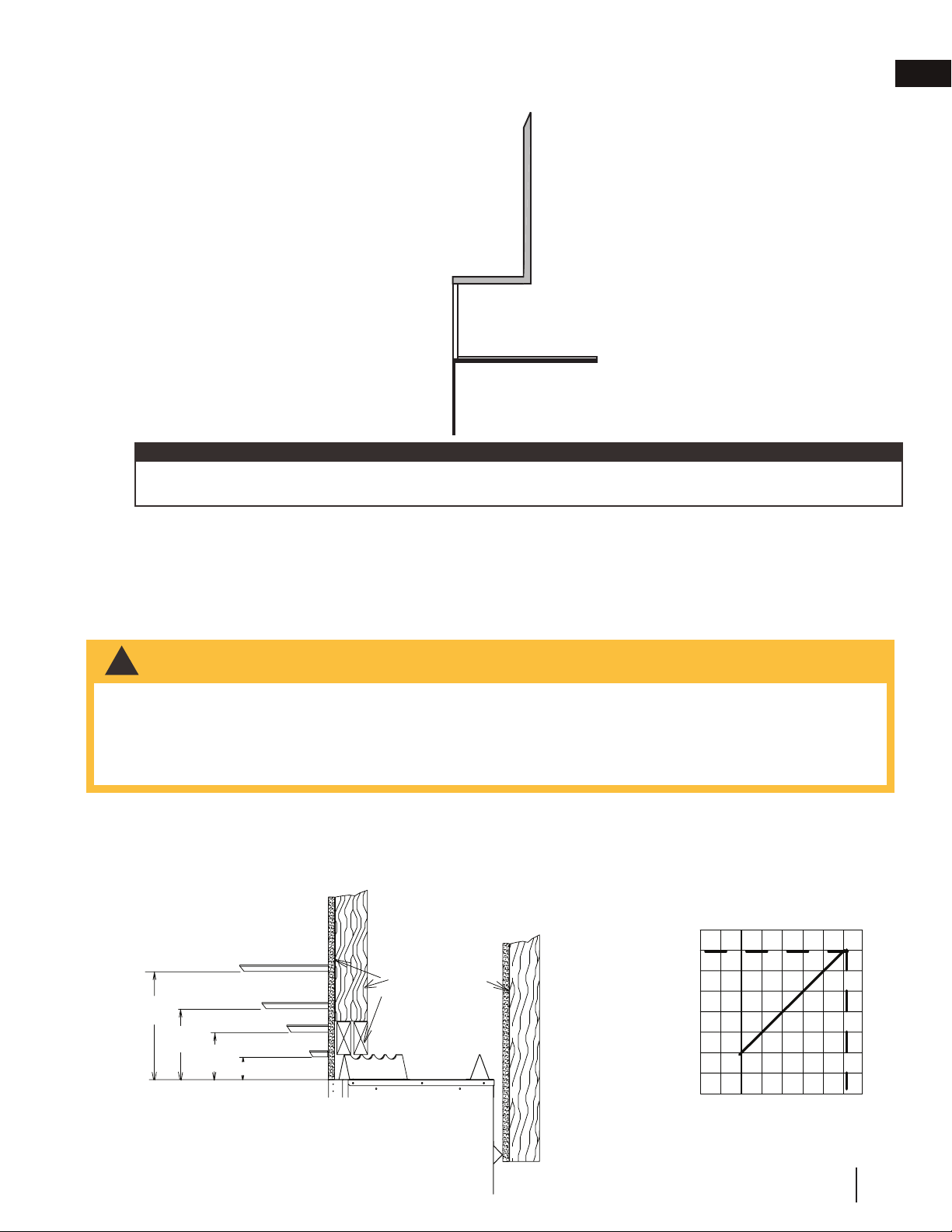
Combustible materials may be installed flush with the front of the appliance but must not cover any of the black
face-areas of the appliance. Non-combustible material (brick, stone or ceramic tile) may protrude in these areas.
Combustible mantel clearance can vary according to the mantel depth. Use the graph to help evaluate the clear-
ance needed.
MANTEL WIDTH
4
31
2
3
7
5
6
75
MATERIALS
STUD
COMBUSTIBLE
H
E
I
G
H
T
M
A
N
T
E
L
TOP OF APPLIANCE
MANTEL
MANTEL
MANTEL
MANTEL
7"
[178mm]
6"
[152mm]
7"
[
178mm]
6"
[152mm]
4"
[102mm]
2"
[51mm]
4"
[102mm]
2"
[51mm]
MANTEL WIDTH
4
31
2
3
7
5
6
75
MATERIALS
STUD
COMBUSTIBLE
H
E
I
G
H
T
M
A
N
T
E
L
TOP OF APPLIANCE
MANTEL
MANTEL
MANTEL
MANTEL
7"
[178mm]
6"
[152mm]
7"
[178mm]
6"
[152mm]
4"
[102mm]
2"
[51mm]
4"
[102mm]
2"
[51mm]
W415-0379 / G / 08.23.18
EN
framing
15
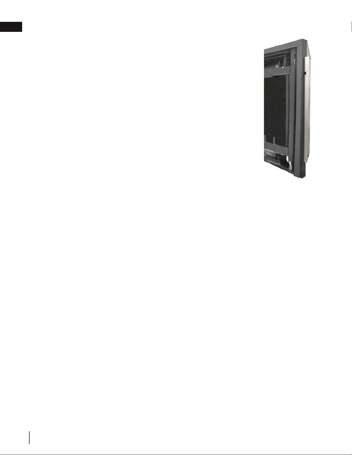
3.5 nailing tab installation
A. Nailing tabs are provided as part of the frames, as shown. To
determine the final location and where to bend the nailing tabs you
must first determine the thickness of your finishing material (i.e.
drywall). This will determine the dimension from the front edge of the
corner post to the nailing tab. Once the nailing tab is in the desired
location and secure using an appropriate fastener*.
* Additional fasteners may be installed.
ADD
IMAGE
HERE
37.1
15
W415-0379 / E / 04.24.12
4.3 MINIMUM MANTEL CLEARANCES
Combustible materials may be installed flush with the front of the appliance but must not cover any of the black
face-areas of the appliance. Non-combustible material (brick, stone or ceramic tile) may protrude in these
areas.
Combustible mantel clearance can vary according to the
mantel depth. Use the graph to help evaluate the clear-
ance needed.
MATERIALS
STUD
COMBUSTIBLE
TOP OF UNIT
7” MANTEL
6” MANTEL
4” MANTEL
2” MANTEL
7”
2”
4”
6”
!
WARNING
RISK OF FIRE, MAINTAIN ALL SPECIFIED AIR SPACE CLEARANCES TO COMBUSTIBLES. FAILURE
TO COMPLY WITH THESE INSTRUCTIONS MAY CAUSE A FIRE OR CAUSE THE APPLIANCE TO
OVERHEAT. ENSURE ALL CLEARANCES (I.E. BACK, SIDE, TOP, VENT, MANTEL, FRONT, ETC.) ARE
CLEARLY MAINTAINED.
WHEN USING PAINT OR LACQUER TO FINISH THE MANTEL, THE PAINT OR LACQUER MUST BE
HEAT RESISTANT TO PREVENT DISCOLOURATION.
73.1
MANTEL WIDTH
4
31
2
3
7
5
6
75
H
E
I
G
H
T
M
A
N
T
E
L
4.4 NAILING TAB INSTALLATION
55.1A
A. Attach the nailing tabs to the corner posts using the 2 sheet metal screws sup-
plied. Secure through the centre of the top and bottom slots in the nailing tab and
then through the existing holes in the corner posts. If there are no existing holes,
follow these instructions:
B. To determine the final location of the nailing tab you must first determine the
thickness of your finishing material (i.e. drywall). This will determine the dimen-
sion from the front edge of the corner post to the nailing tab. Once the nailing tab
is in the desired location, drill through the centre hole of the nailing tab. Secure
with a sheet metal screw*.
* Additional set screws may be installed.
NAILING TAB
W415-0379 / G / 08.23.18
EN
framing
16
4.0 finishing
PHAZER
TM
logs and glowing embers, exclusive to Napoleon, provide a unique and realistic glowing effect that is
different in every installation. Take the time to carefully position the glowing embers for a maximum glowing effect.
Log colours may vary. During the initial use of the appliance, the colours will become more uniform as colour pig-
ments burn in during the heat activated curing process.
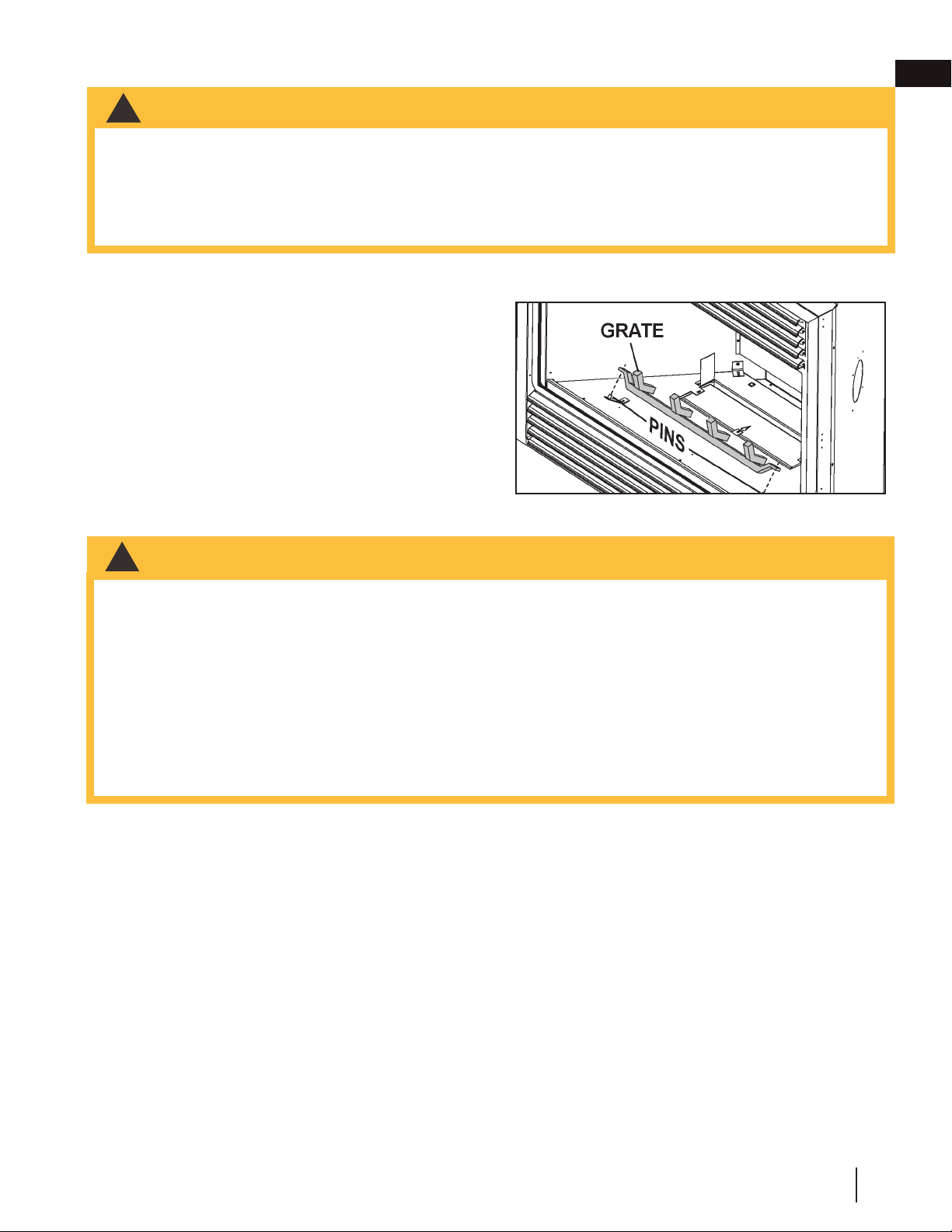
4.1 grate installation
The grate for this appliance has been removed for ship-
ping purposes.
The grate must be installed before the logs are installed.
Remove the packaging from the grate and install onto
the two pins as illustrated.
4.2 log placement
45.2
!
WARNING
• Risk of fi re!
• Never obstruct the front opening of the appliance.
• The front of the appliance must be fi nished with any non-combustible materials such as brick, marble, etc.,
provided that these materials do not go below the specifi ed dimensions as illustrated. As an alternative, you
can fi nish the appliance with drywall, see illustrations to follow.
• Facing and/or fi nishing material must never overhang into the appliance opening.
!
WARNING
• Failure to position the logs in accordance with these diagrams or failure to use only logs specifi cally approved
with this appliance may result in property damage or personal injury.
• Logs must be placed in their exact location in the appliance. Do not modify the proper log positions, since
appliance may not function properly. Delayed ignition and carbon / soot distribution throughout the living area
may occur.
• The logs are fragile and should be handled with care.
• Do not place charcoal embers, vermiculite or charcoal lumps on this burner.
• All previously applied loose material (glowing embers) must be removed prior to reapplication.
• Do not change or substitute the glowing ember material provided with the appliance. If replacing, use only
replacement glowing embers available from your local authorized dealer / distributor.
• Failure to follow these instructions will adversely affect the appliance’s performance and may result in carbon
/ soot deposits inside the appliance and on surrounding surfaces.
48.2
W415-0379 / G / 08.23.18
EN
17
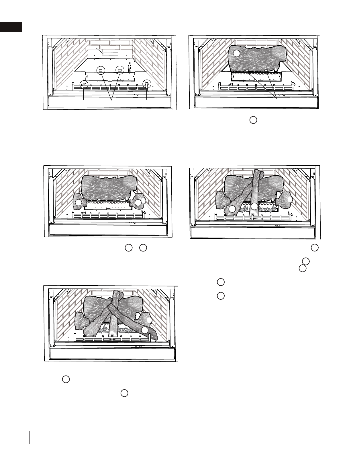
D. Place the bottom of the left crossover log
4
against the left tab of the log support and
against the grate. Place the top of log
4
into
the pocket provided on the back log
1
Posi-
tion the notch located on the end of the center
log
5
against the centre
grate post with the
other end of the log resting in the pocket of
log
4
.
E.
Place the bottom of the right crossover log
6
against the right tab of the log support
and against the grate. Place the top into the
pocket provided on log
5
and allow to rest
against the bracket of the log support.
A.
Prepare for log placement by ensuring the
left, rear, and right tabs of the log support and
firebox bottom are bent up to 90º to aid in
locating the logs.
B. Place the back log
1
onto the base of the firebox.
Ensure that the back of the log rests against the
rear log support on the back wall of the firebox, and
behind the two rear tabs on the firebox bottom.
C.
Move the two small logs
2
&
3
into posi-
tion, place holes in the bottom of the logs over
the studs located on the burner.
17
W415-0379 / E / 04.24.12
D. Place the bottom of the left crossover log
4
against the left tab of the log support and
against the grate. Place the top of log
4
into the pocket provided on the back log
1
Position the notch located on the end of the
center log
5
against the centre grate post
with the other end of the log resting in the
pocket of log
4
.
4
5
6
E. Place the bottom of the right crossover log
6
against the right tab of the log support
and against the grate. Place the top into the
pocket provided on log
5
and allow to rest
against the bracket of the log support.
REAR LOG SUPPORT
LEFT TAB REAR TABS
RIGHT TAB
REAR TABS
1
A. Prepare for log placement by ensuring the
left, rear, and right tabs of the log support and
firebox bottom are bent up to 90º, to aid in
locating the logs.
B. Place the back log
1
onto the base of the fi re-
box. Ensure that the back of the log rests against
the rear log support on the back wall of the fi re-
box, and behind the two rear tabs on the fi rebox
bottom.
2
3
C. Move the two small logs
2
&
3
into posi-
tion, place holes in the bottom of the logs
over the studs located on the burner.
W415-0379 / G / 08.23.18
EN
finishing
18

4.3 glowing embers
4.4 charcoal embers
4.5 vermiculite
4.6 charcoal lumps
22.1
Tear the embers into pieces and loosely layer above the burner ports covering the burner area. Care should be
taken to shred the embers into thin, small irregular pieces as only the exposed edges of the fi bre hairs will glow.
The ember material will only glow when exposed to direct fl ame; however, care should be taken to not
block off the burner ports.
Blocked burner ports can cause an incorrect fl ame pattern, carbon deposits and delayed ignition.
PHAZER™
logs glow when exposed to direct fl ame. Use only certifi ed “glowing embers” and
PHAZER™ logs available from
your local authorized dealer / distributor.
!
WARNING
• Do not block or close off the burner ports. Blocked ports can cause an incorrect fl ame pattern, carbon
deposits and delayed ignition.
22.2
Randomly place the charcoal embers along the front and sides of the log support in a realistic manner.
Fine dust found in the bottom of the bag should not be used.
!
WARNING
• Do not block or close off the burner ports. Blocked ports can cause an incorrect fl ame pattern, carbon
deposits and delayed ignition.
• When supplied, charcoal embers, charcoal lumps and vermiculite are not to be placed on the burner.
note:
Charcoal embers are not to be placed on the burner.
22.3
Sprinkle vermiculite around the charcoal embers.
!
WARNING
• Do not block or close off the burner ports. Blocked ports can cause an incorrect fl ame pattern, carbon
deposits and delayed ignition.
• When supplied, charcoal embers, charcoal lumps and vermiculite are not to be placed on the burner.
note:
Charcoal embers are not to be placed on the burner.
22.4
Place the lumps in front of the logs in a realistic manner taking care not to block or close off any of the burner ports.
!
WARNING
• Do not block or close off the burner ports. Blocked ports can cause an incorrect fl ame pattern, carbon
deposits and delayed ignition.
• When supplied, charcoal embers, charcoal lumps and vermiculite are not to be placed on the burner.
W415-0379 / G / 08.23.18
EN
finishing
19
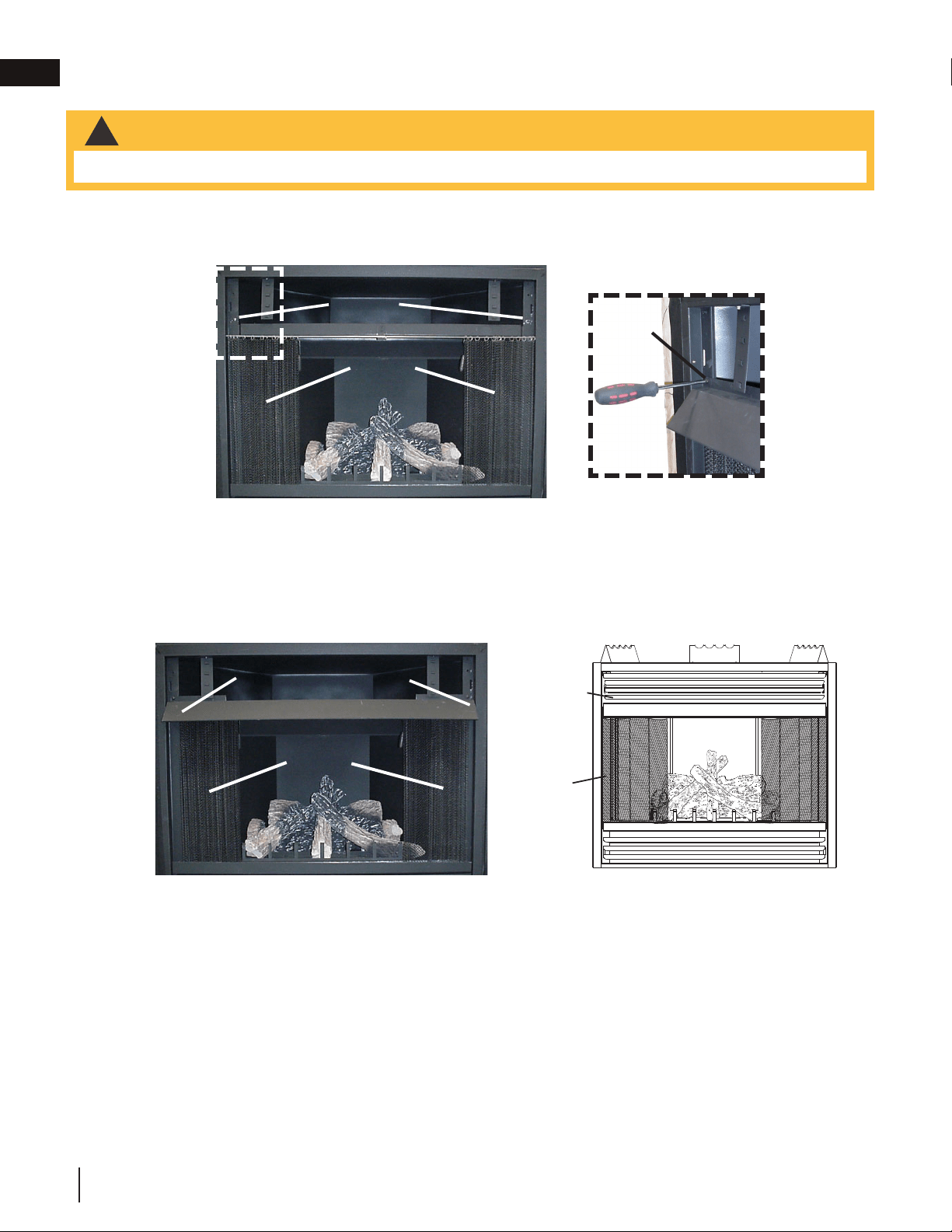
HOOD
SECURING
SCREW
A.
Remove the screws located on either side of the frame, above the curtain rod (Fig. 1).
B. Align the slots on the hood with the holes from which the screws were removed (Fig. 2).
CURTAIN
MESH
SCREWS
HOOD
CURTAIN
MESH
LOUVRE BRACKETS
4.7 hood
!
WARNING
• Appliance screens must be closed while the appliance is in operation.
Fig. 1
C. Secure the hood using the screws removed in step 1. Ensure that the louvre brackets are positioned in
front of the hood (Fig. 3).
D. The curtain mesh must be kept fully closed during operation to help prevent accidental burns from
occurring (Fig. 4).
Fig. 2
Fig. 3
CURTAIN
MESH
HOOD
LOUVRES
Fig. 4
W415-0379 / G / 08.23.18
EN
finishing
20
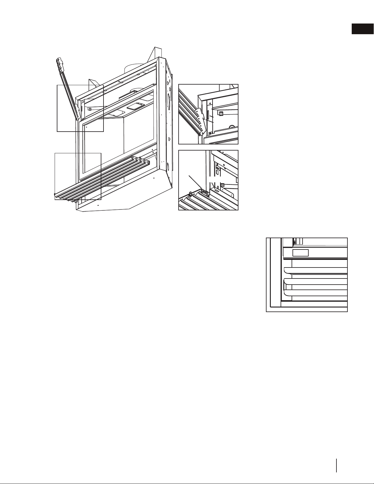
4.8 L42 louvre installation
4.9 logo placement
Remove the backing of the logo supplied and place on the screen cover, as illus-
trated.
LOGO
19
W415-0379 / E / 04.24.12
A
B
A
B
SLOT
TAB
SLOT
HINGE
CLIP
57.1A
UPPER LOUVRES
Insert the louvre tabs into the slots
located at the top left and right corners of
the unit.
LOWER LOUVRES
Insert the hinge clips into the slots lo-
cated at the bottom left and right corners
of the unit.
To remove the louvres, pull the back tabs
of the clips forward, while pushing the
louvre assembly back. Lift the clip.
5.8 L42 LOUVRE INSTALLATION
5.9 LOGO PLACEMENT
Remove the backing of the logo supplied and place on the screen cover, as
indicated.
LOGO
D. The curtain mesh must be kept fully closed
during operation to help prevent accidental
burns from occurring.
CURTAIN
MESH
HOOD
LOUVRES
UPPER LOUVRES
Insert the louvre tabs into the slots lo-
cated at the top left and right corners of
the appliance.
LOWER LOUVRES
Insert the hinge clips into the slots lo-
cated at the bottom left and right corners
of the appliance.
To remove the louvres, pull the back tabs
of the clips forward, while pushing the
louvre assembly back. Lift the clip.
W415-0379 / G / 08.23.18
EN
finishing
21
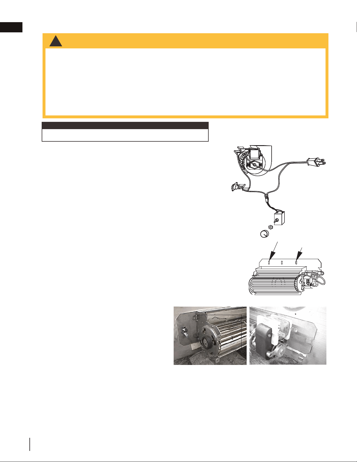
5.0 optional blower installation
!
WARNING
• Risk of fire and electrical shock!
• Turn off the gas and electrical power before servicing this appliance.
• Use only Wolf Steel approved optional accessories and replacement parts with this appliance. Using
non-listed accessories (blowers, doors, louvres, trims, gas components, venting components, etc.) could
result in a safety hazard and will void the warranty and certification.
• Ensure that the fan’s power cord is not in contact with any surface of the appliance to prevent electrical
shock or fire damage. Do not run the power cord beneath the appliance.
• The wire harness provided in the blower kit is a universal harness. When installed, ensure that any excess
wire is contained, prevent it from making contact with moving or hot objects.
35.1
SPECIFIC BLOWER INSTALLATION
INSTRUCTIONS MUST BE ADDED HERE.
THIS TEMPLATE MUST BE USED WITH ANY
APPLIANCE THAT OFFERS THE BLOWER AS
AN OPTION OR COMES STANDARD WITH THE
APPLIANCE... AS PER THE STANDARD.
INSTALLATION TO BE DONE BY A QUALIFIED INSTALLER and must
be electrically connected and grounded in accordance with local codes.
In the absence of local codes, use the current ANSI / NFPA 70 National
Electrical Code.
If the appliance was not previously equipped with a blower: Route a
grounded 2-wire, 60hz power cable to the receptable / junction box. At
this point, it must be strain-relieved and insulated.
The three slots on the blower mounting bracket allow ease of adjust-
ment when attaching the blower. For a quiet running blower, do not
allow the assembly to sit on the firebox base. Slide the vibration reduc-
ing pad (A) into the clip (C) and up against the threaded stud (B) at the
other end. The blower must be able to be positioned entirely onto the
pad.
To ease installation of the blower, remove the hinge screen and valve
control door (lower louvres) from the base of the appliance.
Tilt the blower onto its side. Slide it past the controls and into the clip
(C). Secure to the threaded stud using the lock washer and wiring nut
provided. Ensure that the blower does not touch the appliance base or
the firebox.
Attach the connectors from the black and white
wires to the thermal switch and secure the thermal
switch bracket to the bottom left of the appliance
using the screws provided. Ensure that the thermal
switch touches the firebox wall.
Attach the connectors from the black and red wires
to the blower.
20
W415-0379 / E / 04.24.12
INSTALLATION TO BE DONE BY A QUALIFIED INSTALLER and must
be electrically connected and grounded in accordance with local codes.
In the absence of local codes, use the current ANSI / NFPA 70 National
Electrical Code.
If the appliance was not previously equipped with a blower:
Route a grounded 2-wire, 60hz power cable to the receptacle /
junction box. At this point, it must be strain relieved and insulated.
The three slots on the blower mounting bracket allow ease of
adjustment when attaching the blower. For a quiet running blower, do not allow the
assembly to sit on the firebox base. Slide the vibration reducing pad (A) into the
clip (C) and up against the threaded stud (B) at the other end. The blower must
be able to be positioned entirely onto the pad.
To ease installation of the blower, remove the hinge screen and valve control door
(lower louvres) from the base of the appliance.
Tilt the blower onto its side. Slide it past the controls and into the clip (C).
Secure to the threaded stud using the lock washer and wing nut provided.
Ensure that the blower does not touch the appliance base or the firebox.
Attach the connectors from the black and white
wires to the thermal switch and secure the
thermal switch bracket to the bottom left of the
unit using the screws provided. Ensure that the
thermal switch touches the firebox wall.
Attach the connectors from the black and red
wires to the blower.
black
white
red
VARIABLE
SPEED
SWITCH
BLOWER
THERMAL
SWITCH
SLOTS
ELONGATED
A
B
C
6.0 OPTIONAL BLOWER INSTALLATION
!
WARNING
RISK OF FIRE AND ELECTRICAL SHOCK.
TURN OFF THE GAS AND ELECTRICAL POWER BEFORE SERVICING THIS APPLIANCE.
USE ONLY WOLF STEEL APPROVED OPTIONAL ACCESSORIES AND REPLACEMENT PARTS WITH
THIS APPLIANCE. USING NON-LISTED ACCESSORIES (BLOWERS, DOORS, LOUVRES, TRIMS, GAS
COMPONENTS, VENTING COMPONENTS, ETC.) COULD RESULT IN A SAFETY HAZARD AND WILL
VOID THE WARRANTY AND CERTIFICATION.
ENSURE THAT THE FAN’S POWER CORD IS NOT IN CONTACT WITH ANY SURFACE OF THE
APPLIANCE TO PREVENT ELECTRICAL SHOCK OR FIRE DAMAGE. DO NOT RUN THE POWER
CORD BENEATH THE APPLIANCE.
THE WIRE HARNESS PROVIDED IN THE BLOWER KIT IS A UNIVERSAL HARNESS. WHEN
INSTALLED, ENSURE THAT ANY EXCESS WIRE IS CONTAINED, PREVENTING IT FROM MAKING
CONTACT WITH MOVING OR HOT OBJECTS.
51.5
Refer to blower leaflet for step-by-step installation instructions.
note:
W415-0379 / G / 08.23.18
EN
22
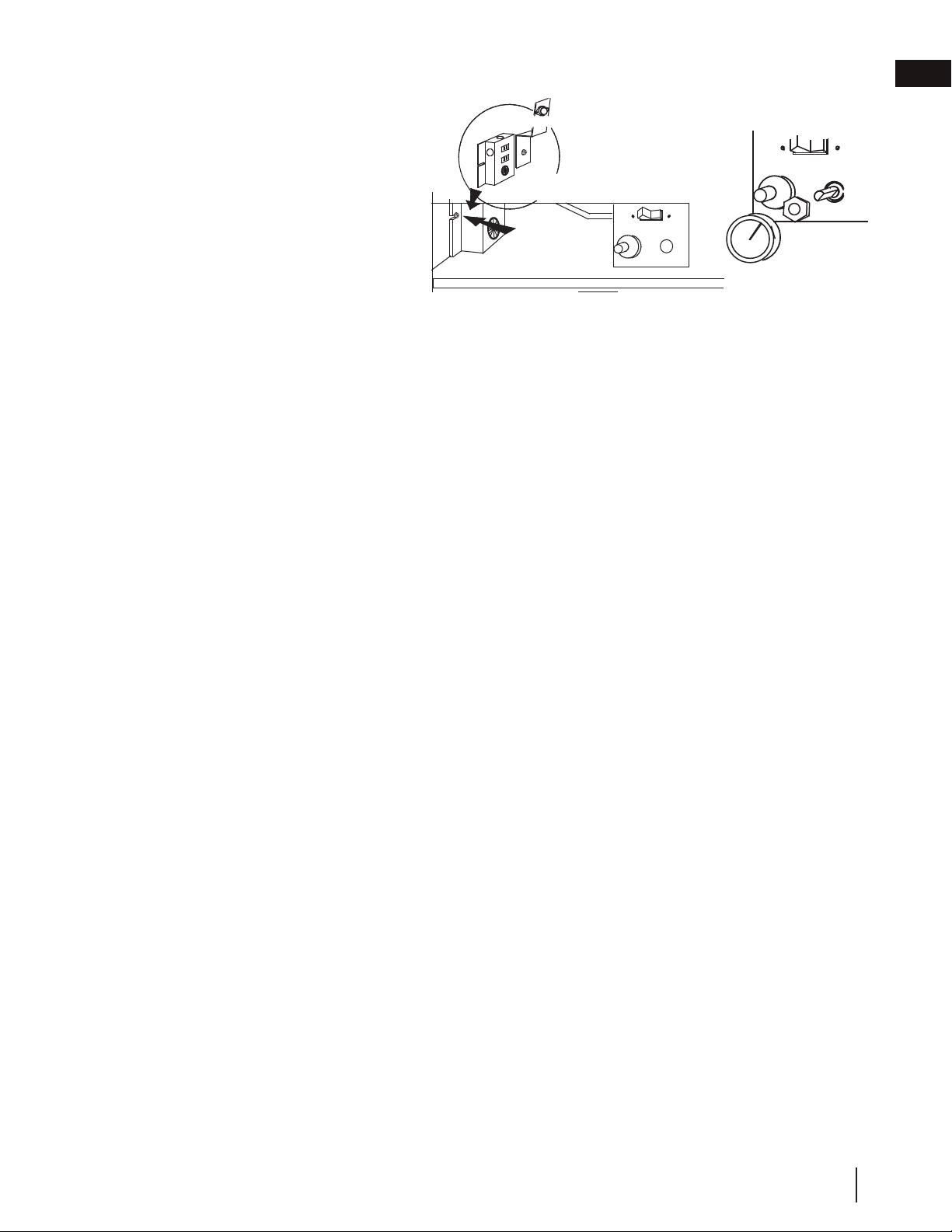
Attach and secure the variable speed switch us-
ing the nut provided. Plug the harness cord into
the receptable. The wire harness provided in
this kit is a universal harness. When installed,
ensure that any excess wire is contained,
preventing it from making contact with
moving or hot objects.
Because the blower is thermally activated,
when turned on, it will automatically start
approximately 10 minutes after lighting the
appliance and will run for approximately 30-45 minutes after the appliance has been turned off. Use of the fan
increases the output of heat. Drywall dust will penetrate into the blower bearings, causing irreparable damage.
Care must be taken to prevent drywall dust from coming into contact with the blower or its compartment. Any
damage resulting from this condition is not covered by the warranty policy.
21
W415-0379 / E / 04.24.12
Attach and secure the variable speed switch
using the nut provided. Plug the harness cord
into the receptacle.The wire harness provided
in this kit is a universal harness. When installed,
ensure that any excess wire is contained,
preventing it from making contact with
moving or hot objects.
Because the blower is thermally activated,
when turned on, it will automatically start
approximately 10 minutes after lighting the
appliance and will run for approximately 30-45 minutes after the appliance has been turned off. Use of the fan
increases the output of heat. Drywall dust will penetrate into the blower bearings, causing irreparable damage.
Care must be taken to prevent drywall dust from coming into contact with the blower or its compartment. Any
damage resulting from this condition is not covered by the warranty policy.
VARIABLE
SPEED
KNOB
51.6
RECEPTACLE /
THERMAL SWITCH
GROUND
SCREW
JUNCTION BOX
W415-0379 / G / 08.23.18
EN
optional blower installation
23
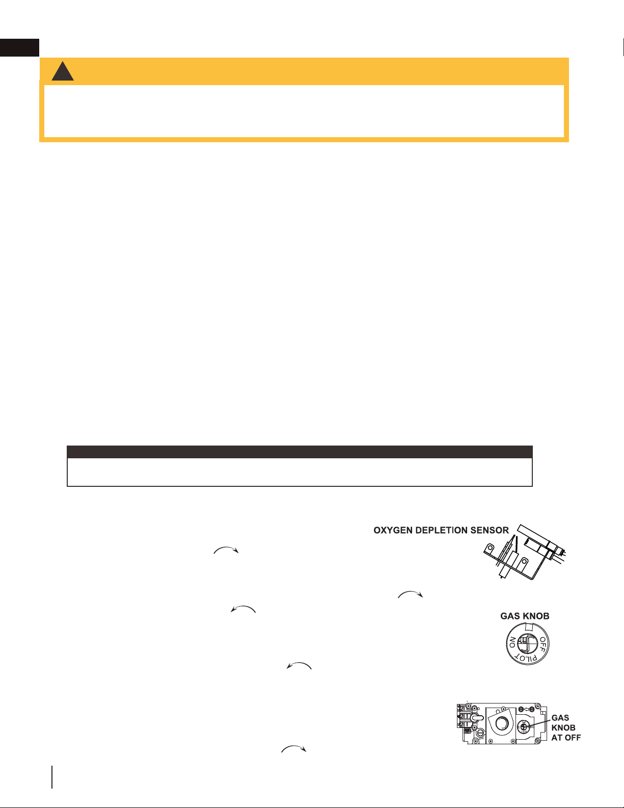
6.0 operation
31.1A
!
WARNING
• Do not turn on if children or other at risk individuals are near the appliance.
• This appliance is equipped with a pilot which must be lit by hand while following these instructions exactly.
• Before operating, smell all around the appliance area for gas and next to the fl oor because some gas is heavier
than air and will settle on the fl oor.
• Use only your hand to turn the gas control knob. Never use tools. If the knob will not turn by hand, do not try
to repair it. Call a qualifi ed service technician. Force or attempted repair may result in a fi re or explosion.
• Do not use this appliance if any part has been under water. Immediately call a qualifi ed service technician
to inspect the appliance and replace any part of the control system and any gas control which has been
underwater.
FOR YOUR SAFETY READ BEFORE LIGHTING
WHAT TO DO IF YOU SMELL GAS
LIGHTING INSTRUCTIONS
TO TURN OFF GAS
A. Stop! Read the above safety information on this label.
B. Remove batteries from the transmitter and set thermostat to lowest setting, if equipped.
C. Turn off all electrical power to the appliance.
D. Open the glass door, if equipped.
E. Turn the gas knob clockwise to the “OFF” position.
F. Wait fi ve (5) minutes to clear out any gas. If you smell gas including near the fl oor, STOP!
Follow the instructions above in the “WHAT TO DO IF YOU SMELL GAS” section. If you
don’t smell gas; close the glass door and go to the next step.
G. If the appliance is equipped with fl ame adjustment valve turn clockwise to “OFF”.
H. Turn gas knob counter-clockwise to the “PILOT” position. (If the appliance is equipped
with an “ON/OFF” switch, ensure it is in the “ON” position.
I. Depress and hold gas knob while lighting the pilot with the push button ignitor. Keep knob
fully depressed for one minute, then release. If pilot does not continue to burn, repeat steps
E through I.
J. With pilot lit, turn gas knob counter-clockwise
to the “ON” position.
K. If equipped with the fl ame adjustment valve, push and turn the knob to high.
L. Turn on all electrical power to the appliance and re-install the batteries into the transmitter, if
equipped. Set thermostat to desired setting, if equipped.
A. Set thermostat to desired setting, if equipped.
B. Turn off all electrical power to the appliance if service is to be performed.
C. Push in gas knob slightly and turn clockwise to the “OFF” position. Do not force.
• Turn off all gas to the appliance.
• Open windows.
• Do not try to light any appliance.
• Do not touch any electric switch; do not use
any phone in your building
• Immediately call your gas supplier from a
neighbour’s phone. Follow the gas supplier’s
instructions.
• If you cannot reach your gas supplier, call
the fi re department.
• If you do not follow these instructions exactly, a fi re or explosion may result causing property damage, personal
injury, or loss of life.
• If applicable, always light the pilot whether for the fi rst time or if the gas supply has run out with the glass door
opened or removed.
add gas knob
add gas valve
Ensure that a continuous gas fl ow is at the burner before installing the door. When lit for the fi rst time, the appliance
will emit an odor for a few hours. This is a normal temporary condition caused by the “burn-in” of paints and
lubricants used in the manufacturing process and will not occur again. After extended periods of non-operation
such as following a vacation or a warm weather season, the appliance may emit a slight odor for a few hours. This
is caused by dust particles in the heat exchanger burning off. In both cases, open a window to suffi ciently ventilate
the room.
For vent free appliances ONLY: if the appliance shuts off, do not relight until you provide fresh air. If appliance
keeps shutting off, have it serviced. Keep burner and control compartment clean.
note:
When lighting and re-lighting, the gas knob cannot be turned from pilot to off unless the knob is
depressed.
22
W415-0379 / E / 04.24.12
FOR YOUR SAFETY READ BEFORE LIGHTING:
Ɣ This appliance is equipped with a pilot which must be lit by hand while following these instructions exactly.
Ɣ
Before operating smell all around the appliance area for gas and next to the floor because some gas is heavier than air and will settle on the floor.
Ɣ Use only your hand to push in and turn the gas control knob. Never use tools. If the knob will not push in and turn by hand, do not try
to repair it. Call a qualified service technician. Force or attempted repair may result in a fire or explosion.
Ɣ Do not use this appliance if any part has been under water. Immediately call a qualified service technician to inspect the appliance
and replace any part of the control system and any gas control which has been under water.
ƔDo not try to light any appliance.
ƔDo not touch any electric switch; do not use any phone in your building.
Ɣ Immediately call your gas supplier from a neighbour’s phone. Follow the gas supplier’s instructions.
Ɣ If you cannot reach your gas supplier, call the fire department.
When lighting and re-lighting, the gas knob cannot be turned from pilot to off unless the knob is depressed.
$ STOP! Read the above safety information on this label.
% Set the thermostat to lowest setting.
& Turn off all electric power to the appliance.
' Open the control door. Turn the gas knob clockwise to off.
( Wait five (5) minutes to clear out any gas. If you smell gas including near the floor, STOP! Follow “B” in the above safety information
on this label. If you don’t smell gas go to the next step.
) Find pilot located in front of the back log.
G. Turn gas knob counter-clockwise to pilot.
H. Depress and hold gas knob while lighting the pilot with the push button ignitor. Keep knob fully depressed for one minute, then
release. If pilot does not continue to burn repeat steps 3 through 7.
, With pilot lit, turn gas knob counter-clockwise to on. When the pilot has been turned off,
ignition of the main burner may be delayed from 1-2 minutes. When the pilot has been left
burning, ignition of the main burner should occur almost immediatley.
- If equipped with remote on-off switch, main burner may not come on when you turn the valve to on. Remote switch must be in
the on position to ignite burner.
K. Turn on all electric power to the appliance.
A. Turn off all electric power to the appliance if service is to be performed.
%Push in gas control knob slightly and turn clockwise to off. Do not force.
WHAT TO DO IF YOU SMELL GAS:
LIGHTING INSTRUCTIONS:
TO TURN OFF GAS
,IDSSOLDQFHVKXWVRIIGRQRWUHOLJKWXQWLO\RXSURYLGHIUHVKDLU,IDSSOLDQFHNHHSVVKXWWLQJRIIKDYHLWVHUYLFHG.HHSEXUQHU
DQGFRQWUROFRPSDUWPHQWFOHDQ
When lit for the first time, the appliance will emit a slight odour for a few hours. This is a normal temporary condition caused by the curing
of the logs and the “burn-in” of internal paints and lubricants used in the manufacturing process and will not occur again. After extended
periods of non-operation such as following a vacation or a warm weather season, the appliance may emit a slight odour for a few hours.
This is caused by dust particles burning off. In both cases, open a window to sufficiently ventilate the room.
47.1
,)<28'2127)2//2:7+(6(,16758&7,216(;$&7/<$),5(25(;3/26,210$<5(68/7
&$86,1*3523(57<'$0$*(3(5621$/,1-85<25/2662)/,)(
,)$33/,&$%/($/:$<6/,*+77+(3,/27:+(7+(5)257+(),5677,0(25,)7+(*$66833/<+$6
581287:,7+7+(*/$66'22523(1('255(029('
!
WARNING
7.0 OPERATION
W415-0379 / G / 08.23.18
EN
24
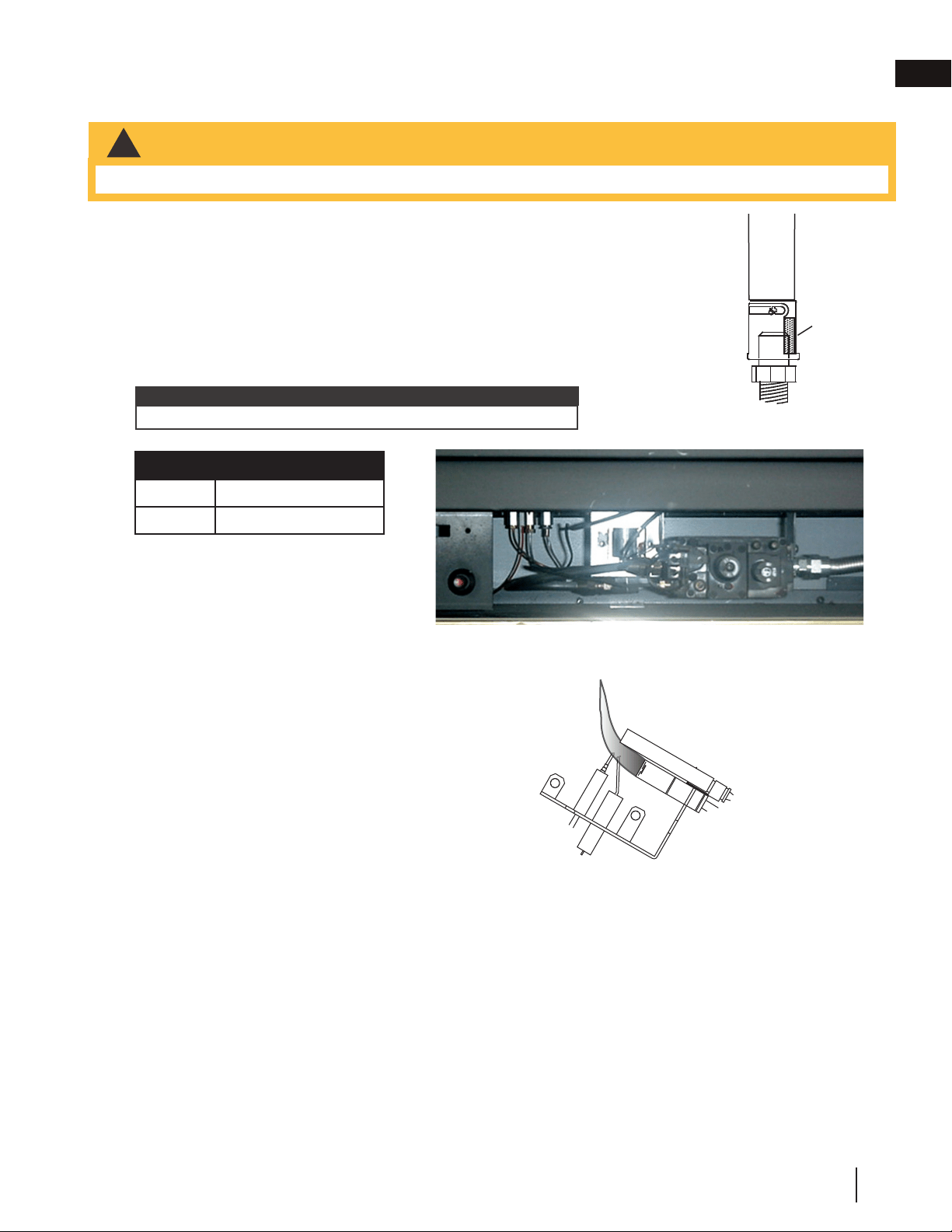
7.0 adjustment
7.1 venturi adjustment
AIR SHUTTER OPENINGS
NG 3/16”
P 7/16”
7.2 flame characteristics
!
WARNING
• Carbon can be distributed in surrounding living area if the air shutter is improperly adjusted.
33.2
This appliance has an air shutter that has been factory set open according to
the chart below:
Regardless of venturi orientation, closing the air shutter will cause a more
yellow flame, but can lead to carbonization. Opening the air shutter will cause
a more blue flame, but can cause flame lifting from the burner ports. The flame
may not appear yellow immediately; allow 15 to 30 minutes for the final flame
colour to be established.
AIR SHUTTER ADJUSTMENT MUST ONLY BE DONE BY A QUALIFIED
INSTALLER!
AIR
SHUTTER
OPENING
VENTURI
BURNER
ORIFICE
33.1
It is important that the orifice is securely inserted into the venturi.
note:
It’s important to periodically perform a visual check of
the pilot and burner flames. Compare them to the
illustration provided. If any flames appear abnormal,
call a service person.
ADD IMAGE
HERE
36.1
23
W415-0379 / E / 04.24.12
8.0 ADJUSTMENT
8.1 VENTURI ADJUSTMENT
CARBON CAN BE DISTRIBUTED IN SURROUNDING LIVING AREA IF THE AIR SHUTTER IS
IMPROPERLY ADJUSTED.
!
WARNING
49.5
This appliance has an air shutter that has been factory set open according
to the chart below:
Regardless of venturi orientation, closing the air shutter will cause a more
yellow flame, but can lead to carboning. Opening the air shutter will cause a
more blue flame, but can cause flame lifting from the burner ports. The
flame may not appear yellow immediately; allow 15 to 30 minutes for the
final flame colour to be established.
AIR SHUTTER ADJUSTMENT MUST ONLY BE DONE BY A QUALIFIED
INSTALLER!
AIR
SHUTTER
OPENING
VENTURI
BURNER
ORIFICE
49.1
AIR SHUTTER OPENINGS
NG 3/16”
LP 7/16”
8.2 FLAME CHARACTERISTICS
It’s important to periodically perform a visual check of the pilot and burner flames. Compare them to the illustra-
tions provided. If any flames appear abnormal call a service person.
54.5
W415-0379 / G / 08.23.18
EN
25
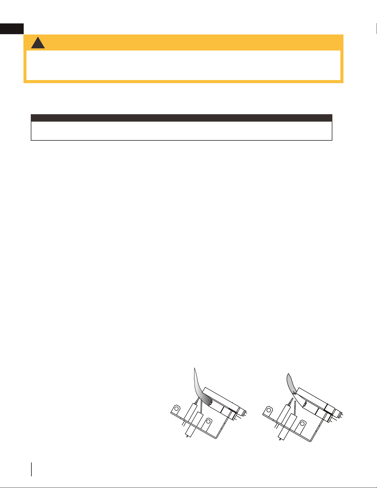
8.0 maintenance
8.1 oxygen depletion sensor pilot cleaning
24.3
!
WARNING
• Turn off the gas and electrical power before servicing the appliance.
• Appliance may be hot. Do not service until appliance has cooled.
• Do not use abrasive cleaners on glass.
• Do not paint the pilot assembly.
This appliance and its venting system should be inspected before use and at least annually by a qualifi ed
service person. The following suggested checks should be performed by a qualifi ed technician. The appliance
area must be kept clear and free of combustible materials, gasoline, or other fl ammable vapors and liquids.
The fl ow of combustion and ventilation air must not be obstructed.
1. In order to properly clean the burner and pilot assembly, remove the logs, rocks and/or glass to ex-
pose both assemblies.
2. Keep the control compartment, media, burner, air shutter opening and the area surrounding the appli-
ance clean by vacuuming or brushing, at least once a year.
3. Check to see that all burner ports are burning. Clean out any of the ports which may not be burning
or are not burning properly.
4. Check to see that the pilot fl ame is large enough to engulf the fl ame sensor and/or thermocouple /
thermopile as well as it reaches the burner.
5. If your appliance is equipped with a safety barrier, cleaning may be necessary due to excessive lint /
dust from carpeting, pets, etc. simply vacuum using the brush attachment.
6. If your appliance is equipped with relief doors, ensure the system performs effectively. Check that the
gasket is not worn or damaged. Replace if necessary.
7. Replace the cleaned logs, rocks or glass. Failure to properly position the media may cause carboning
which can be distributed in the surrounding living area, inside the fi rebox and on exterior surfaces sur-
rounding vent termination.
8. Check to see that the main burner ignites completely on all ports when turned on. A 5 to 10 second
total light-up period is satisfactory. If ignition takes longer, consult your local authorized dealer / dis-
tributor.
9. Visually inspect the appliance for carbon build up. Using a small whisk or brush, brush off the carbon
and vacuum up or sweep into garbage.
10. This step is not applicable for Vent Free appliances: Check to see that the appliance is vent-
ing correctly. Ensure chimney system is safe and unobstructed. (If for any reason the vent air intake
system is disassembled, re-install and re-seal per the instructions provided for the initial installation).
Caution: Label all wires prior to disconnection when servicing controls. Wiring errors can cause improper and
dangerous operation. Verify proper operation after servicing.
note:
This procedure must be performed by a qualified
service person!
Inspect the pilot for any visible contamination or
debris (usually lint, pet hair, spider webs, carpet
fibre, etc.) and remove.
Disconnect the pilot from the pilot tubing line,
using the appropriate wrench. Blow out the
housing in the same direction as the gas flow.
Re-install the pilot tube, turn on the gas and
check for leaks.
If this does not improve the performance, replace
the ODS with an exact replacement. The device is
tamper resistant with no field serviceable parts.
CORRECT PILOT FLAME
Flame contacts thermocouple
correctly (clean, stable and
pronounced blue flame).
INCORRECT PILOT FLAME
Flame lifts off thermocouple
(flame becomes unstable with
more of an orange tip).
30.1
ADD IMAGE
HERE
HOUSING
W415-0379 / G / 08.23.18
EN
26

8.2 care of plated parts
6.1
If the appliance is equipped with plated parts, you must clean fi ngerprints or other marks from the plated surfaces
before operating the appliance for the fi rst time. Use an ammonia-free or vinegar-based cleaner and a towel
to clean. If not cleaned properly before operating for the fi rst time, the marks can cause permanent blemishes
on the plating. After the plating is cured, the fi ngerprints and oils will not affect the fi nish and little maintenance
is required, just wipe clean as needed. Prolonged high temperature burning with the door ajar may cause
discolouration on plated parts.
The protective wrap on plated parts is best removed when the assembly is at room temperature but this can
be improved if the assembly is warmed (i.e. using a hair dryer or similar heat source).
note:
W415-0379 / G / 08.23.18
EN
maintenance
27

9.0 replacement parts
!
WARNING
26.1
• Failure to position the parts in accordance with this manual or failure to use only parts specifi cally approved
with this appliance may result in property damage or personal injury.
Contact your dealer for questions concerning prices and policies on replacement parts. Normally, all parts can
be ordered through your Authorized dealer / distributor.
For warranty replacement parts, a photocopy of the original invoice will be required to honour the
claim.
When ordering replacement parts always give the following information:
• Model & Serial Number of appliance
• Installation date of appliance
• Part number
• Description of part
• Finish
Parts, part numbers, and availability are subject to change without notice.
Parts identifi ed as stocked will be delivered within 2 to 5 business days for most delivery
destinations.
Parts not identifi ed as stocked will be delivered within a 2 to 4 week period, for most cases.
Parts identifi ed as ‘SO’ are special order and can take up to 90 days for delivery.
W415-0379 / G / 08.23.18
EN
28
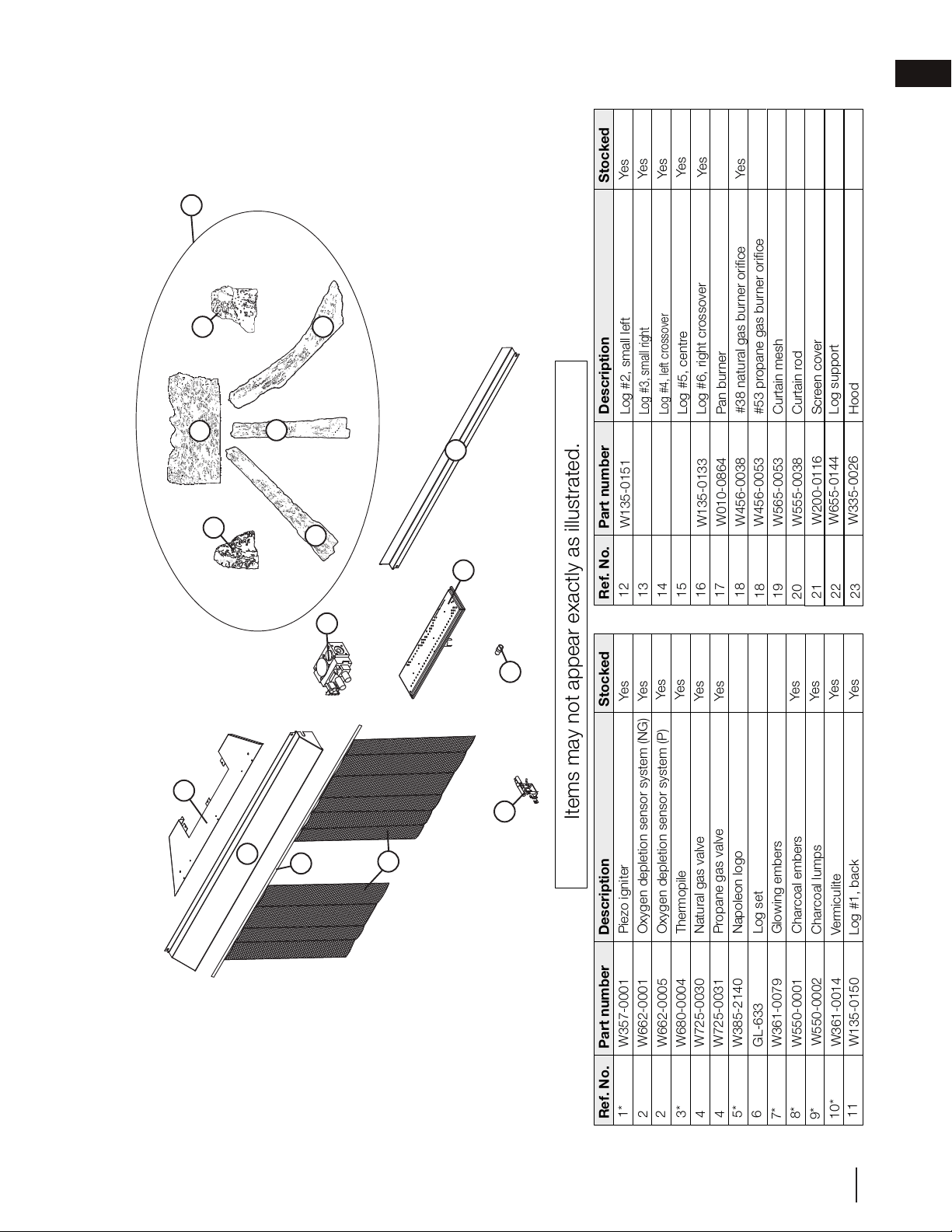
Ref. No.
Part number
Description
3*
4
4
5*
6
Ref. No.
Part number
Description
GVF42-1 REPLACEMENT PARTS
Items may not appear exactly as illustrated.
W357-0001
Piezo igniter
W680-0004
Thermopile
2
1*
Stocked
Stocked
Yes
12
13
14
15
10*
Yes
Log #6, right crossover
W135-0133
W725-0031
Propane gas valve
W725-0030
Natural gas valve
Yes
Yes
Log #4, left crossover
W135-0131
Log #3, small right
W135-0152
9*
W662-0001
Oxygen depletion sensor system (NG)
Log #2, small left
W135-0151
8*
16
W555-0038
Curtain rod
18
W565-0053
Curtain mesh
W456-0053
#53 propane gas burner orifice
Yes
7*
W200-0116
Screen cover
17
W385-2140
Napoleon logo
GL-633
Log set
Glowing embers
W361-0079
Charcoal embers
W550-0001
W550-0002
18
19
20
21
Log #5, centre
W135-0132
#38 natural gas burner orifice
W456-0038
Yes
W010-0864
Pan burner
W361-0014
Charcoal lumps
Vermiculite
6
05.29.18
22
23
11
W135-0150
Log #1, back
W655-0144
W335-0026
Log support
Hood
Yes
Yes
Yes
Yes
Yes
Yes
Yes
Yes
Yes
Yes
12
13
14
11
15
16
17
18
19
20
22
23
21
2
4
* Parts not illustrated.
GL-633
2
W662-0005
Oxygen depletion sensor system (P)
Yes
9.1 GVF42-1 overview
W415-0379 / G / 08.23.18
EN
replacement parts
29
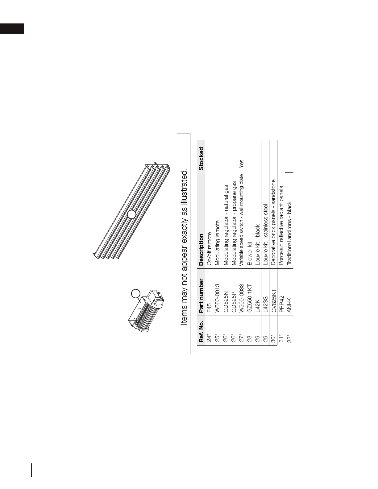
10.0 accessories
Ref. No.
Part number
Description
26*
26*
27*
28
29
29
GVF42-1 ACCESSORIES
Items may not appear exactly as illustrated.
F45
On/off remote
GD825P
Modulating regulator - propane gas
25*
24*
Stocked
GD825N
Modulating regulator - natural gas
GZ550-1KT
Blower kit
W500-0033
Variable speed switch - wall mounting plate
Yes
32*
W660-0013
Modulating remote
31*
30*
L42K
Louvre kit - black
L42SS
Louvre kit - stainless steel
29
28
05.29.18
* Parts not illustrated.
GV825KT
PRP42
ANI-K
Decorative brick panels - sandstone
Porcelain reflective radiant panels
Traditional andirons - black
W415-0379 / G / 08.23.18
EN
accessories
30
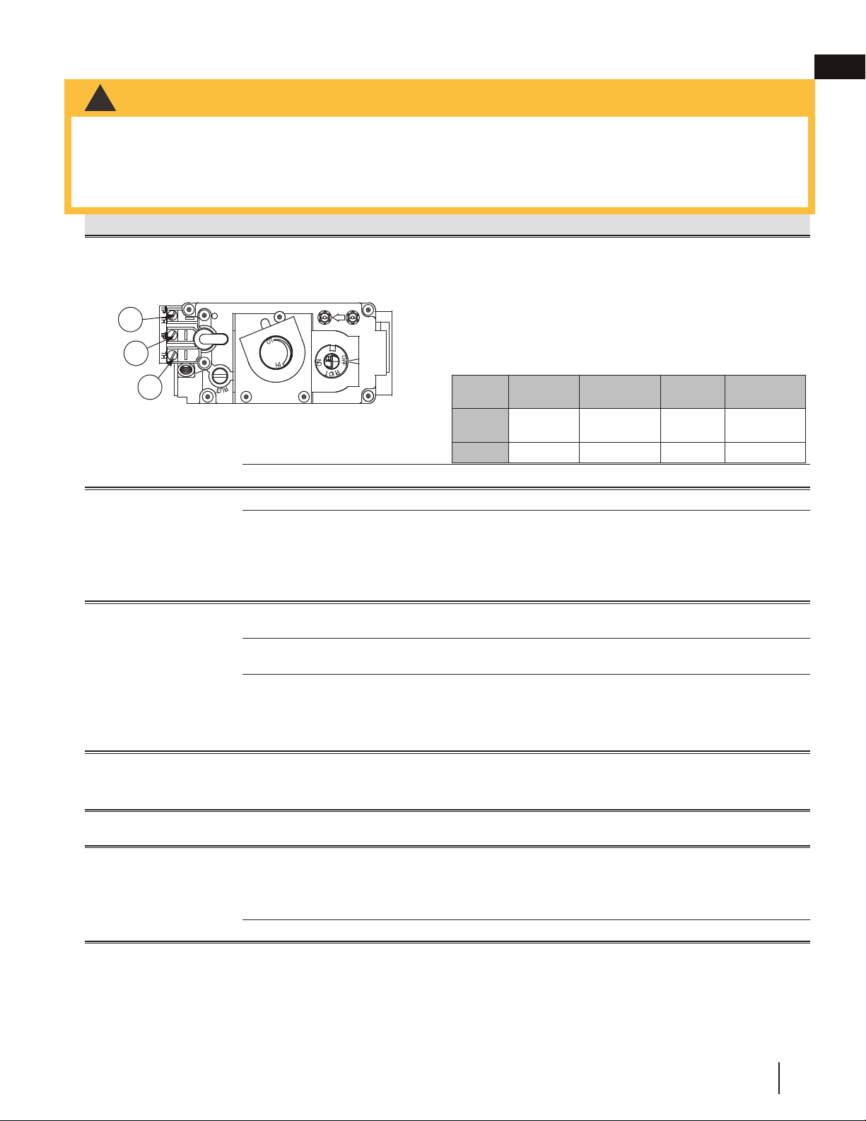
11.0 troubleshooting
27.4
symptom problem test solution
Flames are consistently too
large or too small.
Carboning occurs.
Appliance is over-fi red or
underfi red.
- Check pressure readings:
Inlet pressure can be checked by turning screw (A) counter-clockwise
2 or 3 turns and then placing pressure gauge tubing over the test
point. Gauge should read as described on the chart below. Check that
main burner is operating on ‘HI’. Outlet pressure can be checked the
same as above using screw (B). Gauge should read as described on
the chart below. Check that main burner is operating on ‘HI’. AFTER
TAKING PRESSURE READINGS, BE SURE TO TURN SCREWS
CLOCKWISE FIRMLY TO RESEAL. DO NOT OVER TORQUE.
Leak test with a soap and water solution.
Air shutter improperly adjusted. - Return air shutter to specifi ed opening, see “venturi adjustment” section.
Carbon is being deposited
on glass, logs, rocks,
media or combustion
chamber.
Air shutter has become blocked. - Ensure air shutter opening is free of lint or other obstructions.
Flame is impinging on the
glass, logs, rocks, media or
combustion chamber.
- Check that the logs are correctly positioned.
- Check for ceiling or oscillating fans that may be infl uencing the fl ame.
- Open air shutter to increase the primary air. See “venturi adjustment”
section.
- Check the input rate: check the manifold pressure and orifi ce size as
specifi ed by the rating plate.
Exhaust fumes smelled in
room, headaches.
Not enough combustion air. - Increase fresh air supply. (Use one of the methods described in ANSI
Z223.1 / NFPA 54 or the applicable local code.)
Not enough ventilation air. - Increase fresh air supply. (Use one of the methods described in ANSI
Z223.1 / NFPA 54 or the applicable local code.)
Flame is impinging on the logs or
combustion chamber.
- Check that the logs are correctly positioned.
- Open air shutter to increase the primary air. See “venturi adjustment”
section.
- Check the input rate: check the manifold pressure and orifi ce size as
specifi ed by the rating plate values.
Main burner will not light;
or is slow to light, noisy
pilot.
Inlet pressure too high. - Adjust inlet pressure to ensure 7.0” W.C. (17.4mb) at gas valve for
natural gas and 13.0” W.C. (32.4mb) for propane.
Pilot fl ame blowing off, missing
thermopile.
Pilot is not functioning
properly.
Pilot has been painted - Using a piece of sandpaper or emery cloth remove the paint from the
pilot hood, ignitor and fl ame sensor.
Pilot goes out while
standing; Main burner is in
‘OFF’ position.
Gas piping is undersized. - Turn on all gas appliances and see if pilot fl ame fl utters, diminishes or
extinguishes, especially when main burner ignites. Monitor appliance
supply working pressure.
- Check if supply piping size is to code.
- Correct all undersized piping.
Pilot fl ame is not large enough. - ODS Burner requires checking.
INSERT
PHOTO
OF VALVE
HERE
Pressure
Natural Gas
(inches)
Natural Gas
(millibars)
Propane
(inches)
Propane
(millibars)
Inlet
* 7”
(MIN. 4.5”)
17.4mb
(MIN. 11.2mb)
13”
(MIN. 11”)
32.4mb
(MIN. 27.4mb)
Outlet
3.5” 8.7mb 10” 24.9mb
* Maximum inlet
pressure not to
exceed 13”
• Always light the pilot whether for the fi rst time or if the gas supply has run out with the glass door open or removed.
• Turn off the appliance completely and let cool before servicing. Only a qualifi ed service person should service and
repair this electric appliance.
• Appliance may be hot, do not service until appliance has cooled.
• Do not use abrasive cleaners.
!
WARNING
3
1
2
SIT MILLIVOLT
ROBERT SHAW
P
I
L
O
T
3
1
2
W415-0379 / G / 08.23.18
EN
31
symptom problem test solution
Pilot will not light. Out of propane gas. - Fill the tank.
No spark at pilot burner. - Check if pilot can be lit by a match.
- Check that the wire is connected to the push button ignitor.
- Check if the push button ignitor needs tightening.
- Replace the wire if the wire insulation is broken or frayed.
- Replace the electrode if the ceramic insulator is cracked or broken.
- Replace the push button ignitor.
No gas at the pilot burner. - Check that the manual valve is turned on.
- Check the pilot orifi ce for blockage.
- Replace the valve / Oxygen Depletion Sensor System.
- Call the gas distributor.
Pilot burning; no gas to
main burner; gas knob
is on ‘HI’; wall switch /
thermostat is on.
Thermostat or switch is
defective.
- Connect a jumper wire across the wall switch terminals; if main burner
lights, replace switch / thermostat.
Wall switch wiring is defective. - Disconnect wires from valve. Connect a jumper wire across terminals
1 & 3; if the main burner lights, check the wires for defects and / or
replace wires.
Main burner orifi ce is plugged. - Remove stoppage in orifi ce.
Faulty valve. - Replace.
Pilot goes out when the
gas knob is released.
The gas valve has an
interlock device which
will not allow the pilot
burner to be lit until
the thermocouple
has cooled. Allow
approximately 60
seconds for the
thermocouple to cool.
System is not correctly purged. - Purge the gas line.
Out of propane gas. - Fill the tank.
Pilot fl ame is not large enough.
(Supply pressure too low.)
- Service or replace Oxygen Depletion Sensor System.
- Correct piping and / or regulator to provide correct pressure.
- Ensure adequate supply pressure.
Thermocouple shorting / faulty. - Loosen and tighten thermocouple.
- Clean thermocouple and valve connection.
- Replace Oxygen Depletion Sensor System.
- Test and replace valve.
Faulty valve / high low knob
does not depress smoothly.
- Replace.
Main burner goes out;
pilot stays on.
Pilot fl ame is not large enough
or not engulfi ng the thermopile.
- Ensure adequate supply pressure.
- Replace pilot assembly.
Thermopile shorting / loose
connection.
- Clean thermopile connection to the valve. Reconnect.
- Replace thermopile / valve.
Remote wall switch wire is too
long; too much resistance in the
system.
- Shorten wire to connect length or wire gauge.
Faulty thermostat or switch. - Replace.
Main burner goes out;
pilot goes out.
Insuffi cient air supply. - Open window or door. (Use one of the methods described in ANSI
Z223.1 / NFPA54 or the applicable local code.)
- Have room checked for adequate air exchange.
- See “combustion and ventilation air provisions” section to ensure
adequate air supply.
Out of propane gas. - Fill the tank.
Pilot fl ame is not large enough.
(Supply pressure too low.)
- Service or replace Oxygen Depletion Sensor System.
Remote wall switch is
in “off” position; main
burner comes on when
gas knob is turned to
“ON” position.
Wall switch mounted upsidedown.
- Reverse.
Wall switch is grounding. - Replace.
Wall switch wire is grounding. - Check for ground (short); repair ground or replace wire.
Faulty valve. - Replace.
INSERT
PHOTO
OF PILOT
HERE
27.4_2
23
W415-0379 / E / 04.24.12
8.0 ADJUSTMENT
8.1 VENTURI ADJUSTMENT
CARBON CAN BE DISTRIBUTED IN SURROUNDING LIVING AREA IF THE AIR SHUTTER IS
IMPROPERLY ADJUSTED.
!
WARNING
49.5
This appliance has an air shutter that has been factory set open according
to the chart below:
Regardless of venturi orientation, closing the air shutter will cause a more
yellow flame, but can lead to carboning. Opening the air shutter will cause a
more blue flame, but can cause flame lifting from the burner ports. The
flame may not appear yellow immediately; allow 15 to 30 minutes for the
final flame colour to be established.
AIR SHUTTER ADJUSTMENT MUST ONLY BE DONE BY A QUALIFIED
INSTALLER!
AIR
SHUTTER
OPENING
VENTURI
BURNER
ORIFICE
49.1
AIR SHUTTER OPENINGS
NG 3/16”
LP 7/16”
8.2 FLAME CHARACTERISTICS
It’s important to periodically perform a visual check of the pilot and burner flames. Compare them to the illustra-
tions provided. If any flames appear abnormal call a service person.
54.5
W415-0379 / G / 08.23.18
EN
troubleshooting
32
12.0 warranty
2.1B
Napoleon warrants its products against manufacturing defects to the original purchaser only. Registering your warranty is
not necessary. Simply provide your proof of purchase along with the model and serial number to make a warranty claim.
Napoleon reserves the right to have its representative inspect any product or part thereof prior to honouring any warranty
claim. Provided that the purchase was made through an authorized Napoleon dealer your appliance is subject to the
following conditions and limitations:
Warranty coverage begins on the date of original installation. This factory warranty is non-transferable and may not
be extended whatsoever by any of our representatives. The gas appliance must be installed by a licensed, authorized
service technician or contractor qualifi ed and authorized installer, service agency or supplier. Installation must be done in
accordance with the installation instructions included with the product and all local and national building and fi re codes.
This limited warranty does not cover damages caused by misuse, lack of maintenance, accident, alterations, abuse or
neglect, and parts installed from other manufacturers will nullify this warranty. This limited warranty further does not cover
any scratches, dents, corrosion or discoloring caused by excessive heat, abrasive and chemical cleaners nor chipping
on porcelain enamel parts, mechanical breakage of Phazer™ logs and embers. This warranty extends to the repair or
replacement of warranted parts which are defective in material or workmanship provided that the product has been
operated in accordance with the operation instructions and under normal conditions. After the fi rst year, with respect to
this President’s Lifetime Limited Warranty, Napoleon may, at its discretion, fully discharge all obligations with respect to this
warranty by refunding to the original warranted purchaser the wholesale price of any warranted but defective part(s).
Napoleon will not be responsible for installation, labour, or any other expenses related to the reinstallation of a warranted
part and such expenses are not covered by this warranty. Notwithstanding any provisions contained in the President’s
Lifetime Limited Warranty, Napoleon’s responsibility under this warranty is defi ned as above and it shall not in any event
extend to any incidental, consequential or indirect damages. This warranty defi nes the obligations and liability of Napoleon
with respect to the Napoleon gas appliance and any other warranties expressed or implied with respect to this product,
its components or accessories are excluded. Napoleon neither assumes, nor authorizes any third party to assume, on
its behalf, any other liabilities with respect to the sale of this product. Napoleon will not be responsible for: over-fi ring,
downdrafts, spillage caused by environmental conditions such as rooftops, buildings, nearby trees, hills, mountains,
inadequate vents or ventilation, excessive venting confi gurations, insuffi cient makeup air, or negative air pressures which
may or may not be caused by mechanical systems such as exhaust fans, furnaces, clothes dryers, etc. Any damages to
the appliance, combustion chamber, heat exchanger, plated trim or other components due to water, weather damage, long
periods of dampness, condensation, damaging chemicals or cleaners will not be the responsibility of Napoleon. All parts
replaced under the President’s Limited Lifetime Warranty Policy are subject to a single claim.
During the fi rst 10 years Napoleon will replace or repair the defective parts covered by the lifetime warranty at our discretion
free of charge. From 10 years to life, Napoleon will provide replacement parts at 50% of the current retail price. All parts
replaced under the warranty will be covered for a period of 90 days from the date of their installation. The manufacturer
may require that defective parts or products be returned or that digital pictures be provided to support the claim. Returned
products are to be shipped prepaid to the manufacturer for investigation. If a product is found to be defective, the
manufacturer will repair or replace such defect. Before shipping your appliance or defective components, your dealer must
obtain an authorization number. Any merchandise shipped without authorization will be refused and returned to sender.
Shipping costs are not covered under this warranty. Additional service fees may apply if you are seeking warranty service
from a dealer. Warranty labour allowance is only for the replacement of the warranted part. Travel, diagnostic tests, shipping
and other related charges are not covered by this warranty.
Napoleon products are manufactured under the strict Standard of the world recognized ISO 9001 : 2015 Quality Management
System.
Napoleon products are designed with superior components and materials assembled by trained craftsmen who take great
pride in their work. The burner and valve assembly are leak and test-fi red at a quality test station. The complete appliance is
again thoroughly inspected by a qualifi ed technician before packaging to ensure that you, the customer, receives the quality
product that you expect from Napoleon.
The following materials and workmanship in your new Napoleon gas appliance are warranted against defects for as long
as you own the appliance. This covers: combustion chamber, heat exchanger, stainless / steel burner, Phazer™ logs
and embers, rocks, ceramic glass (thermal breakage only), gold plated parts against tarnishing, porcelainized enameled
components and aluminum extrusion trims.*
Electrical (110V and millivolt) components and wearable parts are covered and Napoleon will provide replacement parts free
of charge during the fi rst year of the limited warranty. This covers: blowers, gas valves, thermal switches, switches, wiring,
remote controls, ignitors, gaskets and pilot assemblies.*
Labour related to warranty repair is covered free of charge during the fi rst year (labour warranty is not applicable for the
Gas Log Sets). Repair work, however, requires the prior approval of an authorized company offi cial. Labour costs to the
account of Napoleon are based on a predetermined rate schedule and any repair work must be done through an authorized
Napoleon dealer.
* Construction of models vary. Warranty applies only to components included with your specifi c appliance.
Napoleon Gas Appliance President’s Lifetime Limited Warranty
Conditions and Limitations
All specifi cations and designed are subject to change without prior notice due to on-going product improvements. Napoleon is a registered
trademark of Wolf Steel Ltd.
W415-0379 / G / 08.23.18
EN
33
NAPOLEON CELEBRATING OVER 40 YEARS
OF HOME COMFORT PRODUCTS
7200, Route Transcanadienne, Montréal, Québec H4T 1A3
24 Napoleon Road, Barrie, Ontario, Canada L4M 0G8
214 Bayview Drive, Barrie, Ontario, Canada L4N 4Y8
103 Miller Drive, Crittenden, Kentucky, USA 41030
Phone: 1-866-820-8686
napoleonproducts.com