Loading ...
Loading ...
Loading ...
Page 17
INSTALLATION MANUAL ECO-55 / ECO-55 CT / ECO-55 ST
ENGLISH
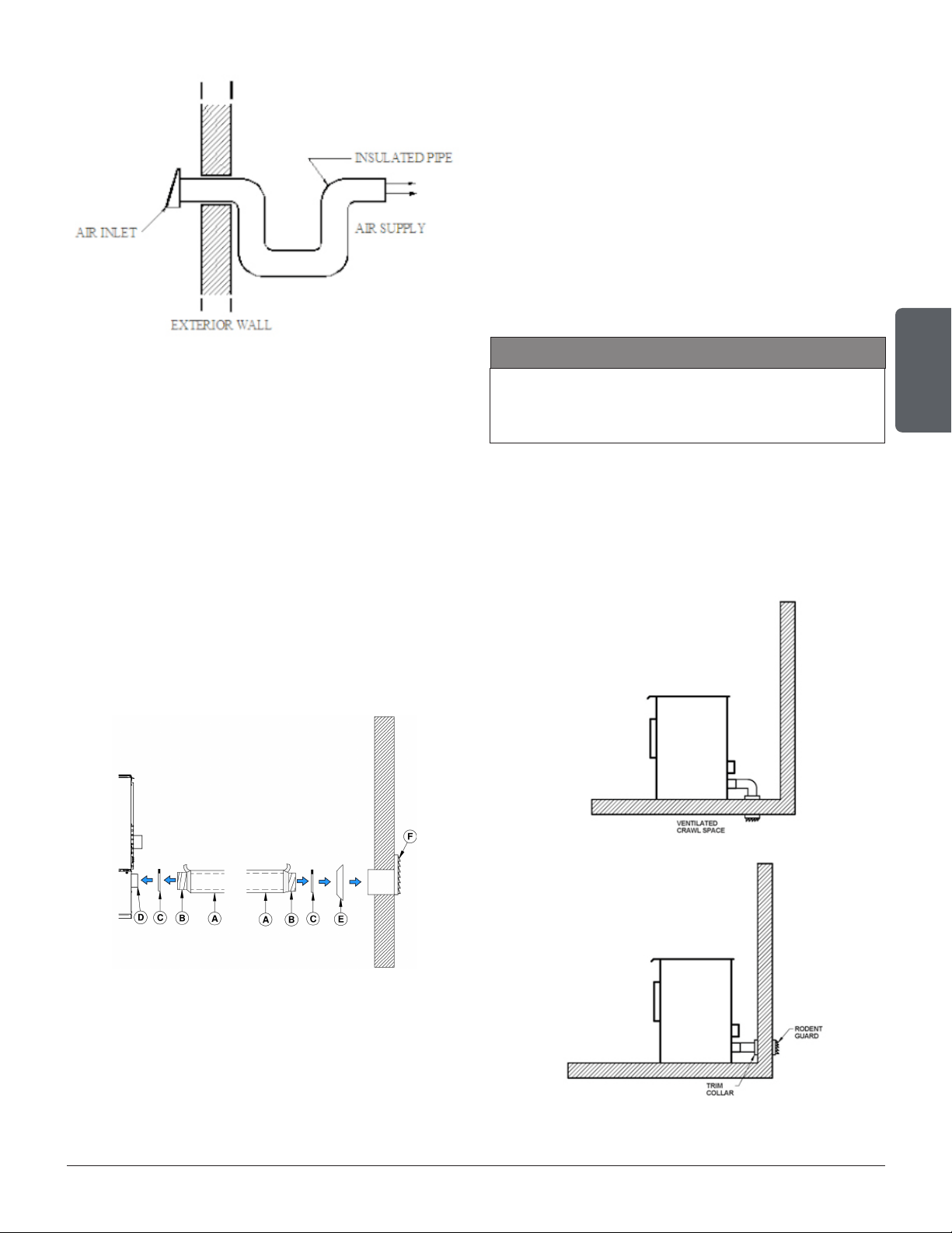
An insulated 3” inside diameter metallic pipe, either
exible or rigid, must be attached to the fresh air in-
take (D).
To complete the installation, make a hole of 1/4" to
1/2" (6 mm à 13 mm) bigger than the insulate pipe
diameter in the outside wall of the house at the
chosen location. From outside, place the outside air
inlet cap (E) in the hole (open side down) and fasten
the register to the wall, with screw.
Place the insulated pipe (A) over the register tube
and over the replace outside air connector (D).
At each end, carefully pull back the insulation and
plastic cover, exposing the exible pipe. Attach the
exible pipe using pipe clamps(C).
For a better seal, you may also use aluminum tape.
Wrap the tape around the joint between the exible
pipe and the air inlets. Carefully push the insulation
and plastic cover back over the pipe. Fix the plastic
in place using aluminum tape.
A rodent guard (minimum 1/4” wire mesh) must be
used at the termination. All connections must be
secured and airtight by either using the appropriately
sized hose clamp and/or UL-181-AP foil tape.
Make sure that the fresh air intake back draft shutter
functions freely. The fresh air intake back draft shutter
is located in the back of the stove.
8.1 SOURCES OF OUTSIDE COMBUSTION
AIR
CAUTION
IT IS FORBIDDEN TO DRAW COMBUSTION AIR
FROM A BASEMENT, AN ATTIC, A GARAGE OR
ANY CONFINED SPACE
• You can draw air from a ventilated crawl space
underneath the oor.
• You can draw air directly from an outside wall,
behind the stove.
Loading ...
Loading ...
Loading ...