Loading ...
Loading ...
Loading ...
13
L’utilisation d’une autre commande murale pourrait produire des résultats inattendus de la
porte ainsi que le dysfonctionnement de l’éclairage. Localisez la console murale en vue de
la porte et su samment loin de la porte pour éviter tout contact pendant l’utilisation de la
console. La commande doit être à une hauteur minimale de 1,5 m au-dessus du sol a n que les
jeunes enfants ne puissent pas l’atteindre.
WARNING
!
Use of any other wall control can cause unexpected operation of the door and
loss of lighting feature. Locate wall console within sight of the door but far
enough from door to prevent contacting it while operating the console. Control
must be at least 5 feet above the oor to prevent small children from operating
it.
MAINTENANCE & ADJUSTMENTS
4
Regular Maintenance
Basic monthly maintenance tasks include:
• Contact Reverse Test
• Lubricate door hardware
• Safe-T-Beam® System check
• Door balance
• Remote Battery Replacement (As needed)
• Light Bulb Replacement (As needed)
• Chain/Belt Tension
A. Contact Reverse Test
See page 10.
B. Lubricate Door Hardware
Inspect door rollers and hinges and lubricate as needed using a
light weight general purpose grease.
C. Safe-T-Beam
®
(STB) System Check
Check that both the RED and GREEN LEDs are ON steady. This indicates
the system is working properly. If both LEDs are not ON steady, check
the appropriate items below:
• STB red LED ashes.
– Check for obstruction.
– Check alignment. (See page 16)
– Verify wire routing from STBs to STB connection in powerhead
– Check for signal interference from another Safe-T-Beam® unit
(for multiple door installations).
• No STB red or green LED displayed.
– Check wiring and wire connections
If system appears to be working properly, perform check as follows:
1. Start the door closing.
2. Pass an object through the beam. The door should stop and
reverse to the fully open position.
– Door should remain stationary or move very slowly.
– If door moves quickly, CONTACT A TRAINED DOOR SYSTEM
TECHNICIAN to have your door springs serviced.
• Close the door.
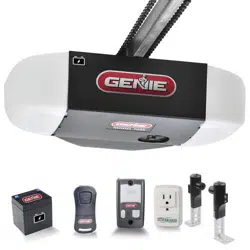
• Place the carriage in the “engage” position (see illustration).
• Operate door using remote or wall control. The carriage will
reattach itself to the drive chain/belt.
DOOR
Engage
Disengage
To disengage carriage from
the turnbuckle, pull handle
down and to the rear.
To engage carriage to
the turnbuckle, pull handle
forward and up.
Release shown in
engaged position
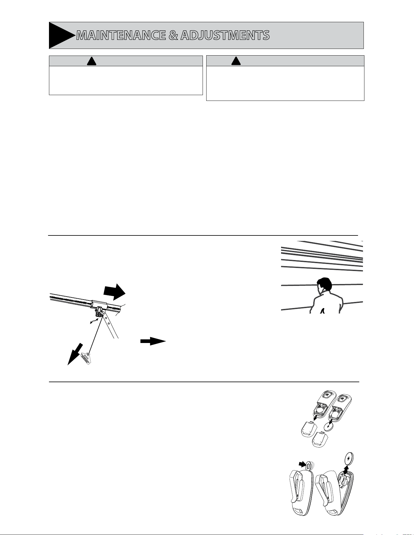
Remote Battery Replacement (1-button)
Replace remote battery with a CR2032 coin cell battery.
1. Slide the battery cover o (it’s the lower half of the remotes case) by pressing on the case just below
the indentation at the top of the cover and sliding it down. Alternately, insert a coin or small washer into
the indentation in the front of the case and pry to unlatch the battery cover in order to slide it o .
2. Slide out the old battery and slide in the new. Be sure positive side (+) is UP.
3. Slide the battery cover on until it snaps into place.
Remote Battery Replacement
(3-button)
Replace remote battery with a CR2032 coin cell battery.
1. Open remote case using a washer or coin that ts into the slot on the top of the remote.
2. Replace battery.
Be sure positive side (+) is UP.
3. Align components and snap case closed.
• Raise and lower the door
manually — it should move
freely and smoothly.
• Raise door manually about
3’ to 4’ feet and let go.
Perform the check as follows:
• With the door closed, pull manual emergency release handle
DOWN and away from door and let go to disengage the carriage
from the drive chain or belt (see illustration).
D. Door Balance (Spring Tension)
E. Remote Battery Replacement (As needed)
DO NOT use release cord to pull door.
AVERTISSEMENT
!
Loading ...
Loading ...
Loading ...