Loading ...
Loading ...
Loading ...
EN
W415-0297 / R / 02.23.21
19
fi nishing
9.0 optional blower installation
!
WARNING
• Risk of fire and electrical shock!
• Turn off the gas and electrical power before servicing this appliance.
• Use only Wolf Steel approved optional accessories and replacement parts with this appliance. Using
non-listed accessories (blowers, doors, louvres, trims, gas components, venting components, etc.) could
result in a safety hazard and will void the warranty and certification.
• Ensure that the fan’s power cord is not in contact with any surface of the appliance to prevent electrical
shock or fire damage. Do not run the power cord beneath the appliance.
• The wire harness provided in the blower kit is a universal harness. When installed, ensure that any excess
wire is contained, prevent it from making contact with moving or hot objects.
ELECTRICAL INSTALLATION TO BE DONE BY A QUALIFIED
INSTALLER and must be connected and grounded in
accordance with local codes. In the absence of local codes,
use the current CSA C22.1 CANADIAN ELECTRICAL CODE in Canada
or the current ANSI/NFPA 70 NATIONAL ELECTRICAL CODE in the
United States.
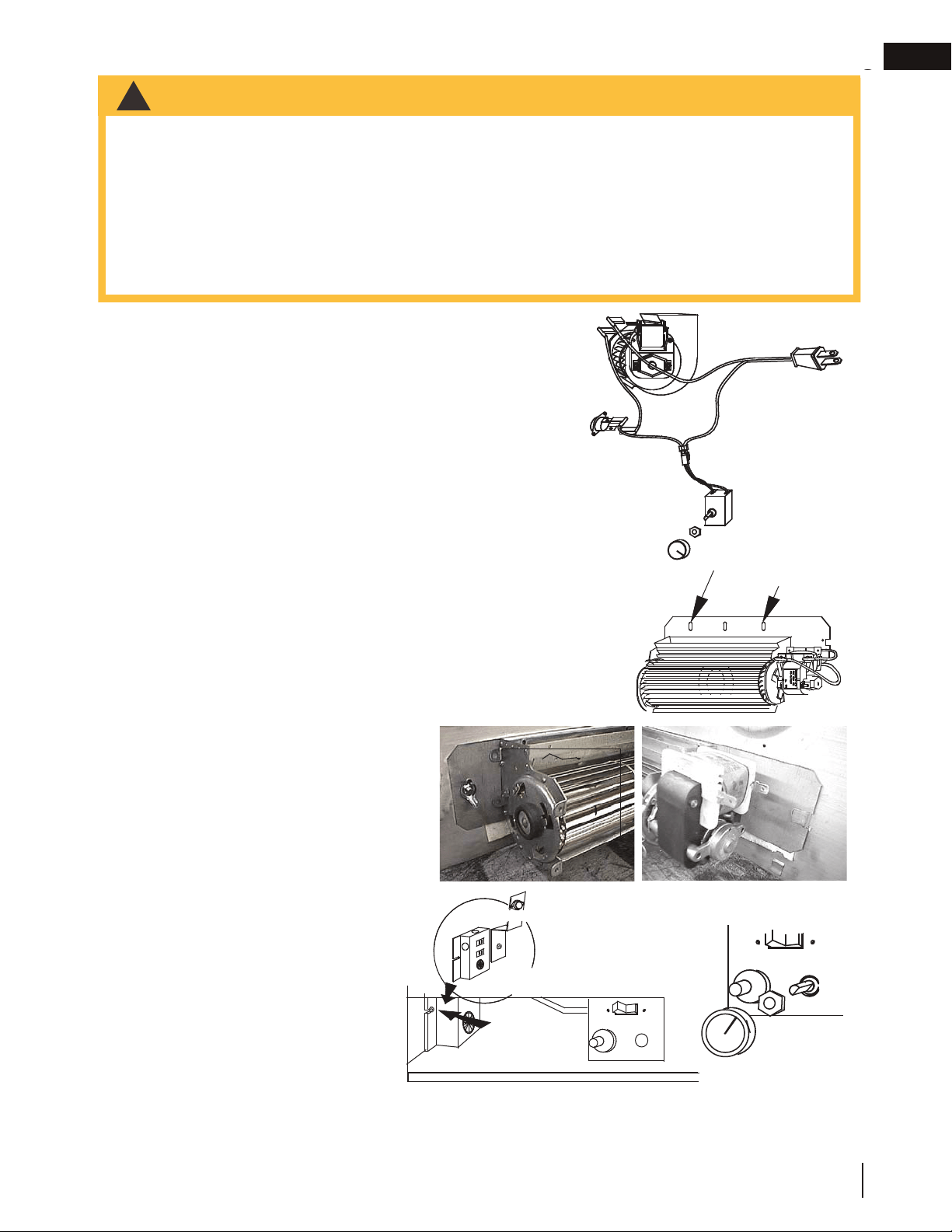
If the fi replace was not previously equipped with a blower: route
a grounded 2-wire, 60hz power cable to the junction box. At this
point, it must be strain relieved and insulated.
The three slots on the mounting bracket allow ease of adjustment
when attaching the blower. For a quiet running blower, do not allow
the assembly to sit on the fi rebox base.
Slide the vibration reducing pad (A) into the clip (C) and up against
the threaded stud (B) at the other end. The blower must be able to be
positioned entirely onto the pad.
To ease installation of the blower, remove the hinge screen and valve control
door (lower louvres) from the base of the appliance.
Tilt the blower assembly onto its side. Slide it past the controls and into the
clip (C). Secure to the threaded stud using the lock washer and wing nut
provided. Ensure that the blower does not touch
the fi replace base or the fi rebox.
Attach the connectors from the black and white
wires to the thermodisc and secure the thermodisc
bracket to the securing stud at the bottom left of
the unit using a lock washer and wing nut. Ensure
that the thermodisc touches the fi rebox wall.
Attach the connectors from the black and red
wires to the blower.
Attach and secure the variable speed switch
using the nut provided. Plug the harness
cord into the receptacle. The wire harness
provided in this kit is a universal harness.
When installed, ensure that any excess wire is
contained, preventing it from making contact
with moving or hot objects.
Because the blower is thermally activated,
when turned on, it will automatically start
approximately 10 minutes after lighting the fi replace and will run for approximately 30-45 minutes after the
fi replace has been turned off. Use of the fan increases the output of heat. Drywall dust will penetrate into the
blower bearings causing irreparable damage. Care must be taken to prevent drywall dust from coming into
contact with the blower or its compartment. Any damage resulting from this condition is not covered by the
warranty policy.
black
white
red
VARIABLE
SPEED
SWITCH
BLOWER
THERMAL
SWITCH
SLOTS
ELONGATED
VARIABLE
SPEED
KNOB
A
B
C
RECEPTACLE /
THERMAL SWITCH
GROUND
SCREW
JUNCTION BOX
Loading ...
Loading ...
Loading ...