Loading ...
Loading ...
Loading ...
www.dimplexrenewables.co.uk 8
8.3
6) The contactors mentioned above in points 3, 4 and 5 are in-
stalled in the electrical distribution system. The mains cables
for the heating elements should be dimensioned and pro-
tected according to DIN VDE 0100.
7) All cables must be installed as permanent wiring.
8) The heat circulating pump (M13) is connected to terminals N
and N1-J13/NO 5.
9) The DHW loading pump (M18) is connected to terminals N
and N1-J13/NO 6.
10) The brine or well pump is connected to terminals N and N1-
J13/NO 3.
11) The return sensor (R2) is integrated into heat pumps for in-
door installation.
The heat pump manager is connected via the following ter-
minals: GND and N1-J2/B2.
12) The external sensor (R1) is connected to terminals GND and
N1-J2/B1.
13) The hot water sensor (R3) is installed in the hot water cylin-
der and is connected to terminals GND and N1-J2/B3.
8 Commissioning
8.1 General Information
To ensure that start-up is performed correctly, it should only be
carried out by an after-sales service technician authorised by the
manufacturer. This may be a condition for extending the guaran-
tee (see Warranty).
8.2 Preparation
The following items need to be checked prior to start-up:
The heat pump must be fully connected, as described in
Chapter 7.
The heat source system and the heating circuit must have
been filled and checked.
The dirt trap must be inserted in the brine inlet of the heat
pump.
All valves that could impair proper flow in the brine and heat-
ing circuits must be open.
The heat pump manager must be adapted to the heating
system in accordance with the controller’s operating instruc-
tions.
8.3 Start-up Procedure
The heat pump is started up via the heat pump manager.
ATTENTION!
The heat pump must be started up in accordance with the installation and
operating instructions of the heat pump manager.
If an overflow valve is fitted to assure the minimum heating water
flow rate, the valve must be set in accordance with the require-
ments of the respective heating system. Incorrect adjustment
can lead to faulty operation and increased energy consumption.
We recommend carrying out the following procedure to correctly
adjust the overflow valve:
Close all of the heating circuits that may also be closed during
operation (depending on the type of heat pump usage) so that
the most unfavourable operating state - with respect to the water
flow rate - is achieved. This normally means the heating circuits
of the rooms on the south and west sides of the building. At least
one heating circuit must remain open (e.g. bathroom).
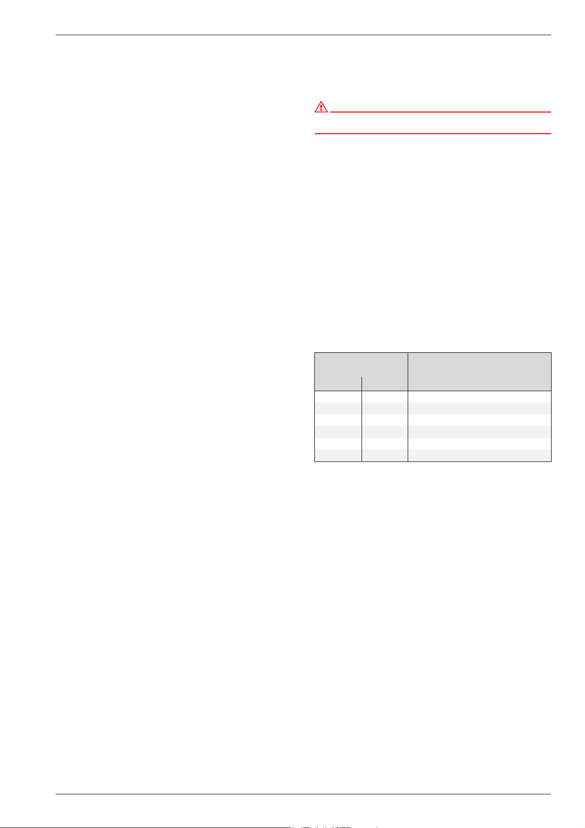
The overflow valve should be opened far enough to produce the
maximum temperature spread between the heating flow and re-
turn flow listed in the table below for the current heat source tem-
perature. The temperature spread should be measured as close
as possible to the heat pump. The heating element of mono en-
ergy systems should be disconnected during start-up.
Heat source
temperature
Max. temperature spread
between heating flow and return
flow
From To
-5° C 0° C 10 K
1° C 5° C 11 K
6° C 9° C 12 K
10° C 14° C 13 K
15° C 20° C 14 K
21° C 25° C 15 K
Loading ...
Loading ...
Loading ...