Loading ...
Loading ...
Loading ...
7
7.5
7.4.2 Mounting the external temperature
sensor
The temperature sensor must be mounted in such a way that all
weather conditions are taken into consideration and the
measured value is not falsified.
On the external wall of a heated room used as living space,
if possible on the north or north-west side of the building
Do not install in a “sheltered position” (e.g. in a wall niche or
under a balcony)
Not in the vicinity of windows, doors, exhaust air vents,
external lighting or heat pumps
Not to be exposed to direct sunlight at any time of year
Sensor lead: Max. length 40 m; min. core cross-section
0.75 mm²; external diameter of the cable 4-8 mm.
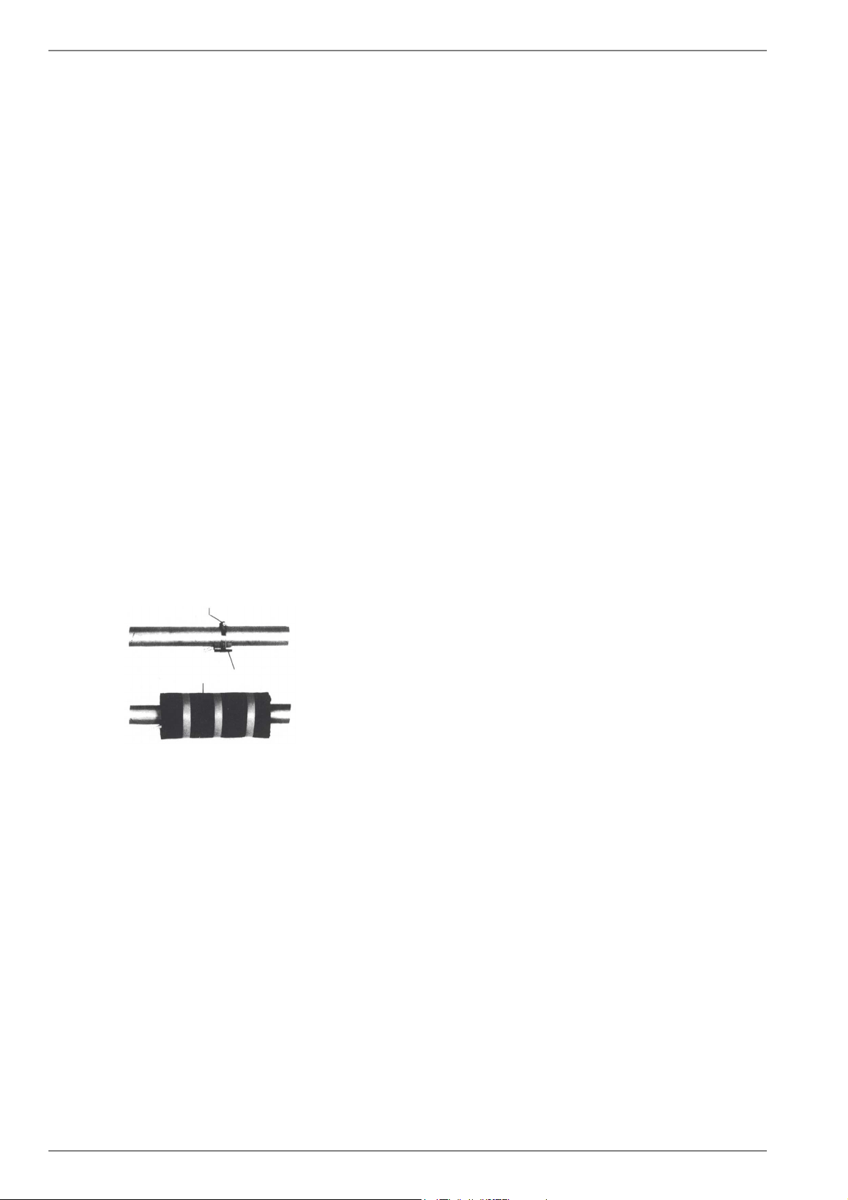
7.4.3 Installing the strap-on sensor
It is only necessary to mount the strap-on sensors if they are
included in the scope of supply of the heat pump but have not yet
been installed.
The strap-on sensors can be fitted as pipe-mounted sensors or
installed in the immersion sleeve of the compact manifold.
Mounting as a pipe-mounted sensor
Remove paint, rust and scale from heating pipe.
Coat the cleaned surface with heat transfer compound
(apply sparingly).
Attach the sensor with a hose clip (tighten firmly, as loose
sensors can cause malfunctions) and thermally insulate.
7.4.4 Hot water distribution system
The KPV compact manifold and the dual differential pressureless
manifold function as an interface between the heat pump, the
heating distribution system, the buffer tank and, in some cases,
even the hot water cylinder. A compact system is used to simplify
the installation process, so that a lot of different components do
not have to be installed individually. Further information can be
found in the relevant installation instructions.
Compact manifold
The return sensor can remain in the heat pump, or should be
installed in the immersion sleeve. The remaining empty space
between the sensor and the immersion sleeve must be filled
completely with heat transfer compound.
DDV 32 dual differential pressureless manifold
In order for the heating circuit pumps of the generator and
consumer circuits to supply the flow to the return sensor, this
must be installed in the immersion sleeve of the dual differential
pressureless manifold.
7.5 Electrical connection
7.5.1 General
During start-up, observe the respective national safety regula-
tions and the applicable VDE safety regulations, particularly
VDE 0100, as well as the technical connection requirements of
the utility companies (EVU) and network operators!
To ensure that the frost protection function of the heat pump
works properly, the heat pump manager must remain connected
to the power supply and the flow must be maintained through the
heat pump at all times.
The switching contacts of the output relay are interference-sup-
pressed. Therefore, depending on the internal resistance of the
measuring instrument, a voltage can also be measured when the
contacts are open. However, this will be much lower than the line
voltage.
Extra-low voltage is connected to controller terminals N1-J1 to
N1-J11; N1-J24 and terminal strip X2; X3. If, due to a wiring er-
ror, the line voltage is mistakenly connected to these terminals,
the heat pump manager will be destroyed.
7.5.2 Electrical installation
1) The supply cable for the output section of the heat pump (up
to 3-core) are fed from the electricity meter of the heat pump
via the utility blocking contactor (if required) into the heat
pump (see heat pump operating instructions for supply volt-
age).
Connection of the mains cable to the control panel of the
heat pump via terminal X6: L/N//PE.
An all-pole disconnecting device with a contact gap of at
least 3 mm (e.g. utility blocking contactor or power contac-
tor) and an all-pole circuit breaker with common tripping for
all external conductors must be installed in the power supply
for the heat pump (tripping current and characteristic in com-
pliance with the device information).
2) The three-core supply cable for the heat pump manager
(heating controller N1) is fed into the heat pump . Connec-
tion of the control line to the control panel of the heat pump
via terminal X1: L/N/PE.
The (L/N/PE~230 V, 50 Hz) supply cable for the heat pump
manager must have a constant voltage. For this reason, it
should be tapped upstream from the utility blocking contac-
tor or be connected to the household current, as important
protection functions could otherwise be lost during a utility
block.
3) The utility blocking contactor(K22) with main contacts and
an auxiliary contact should be dimensioned according to the
heat pump output and must be supplied by the customer.
The NO contact of the utility blocking contactor is looped
from terminal strip G/24 V AC to connector terminal J5/ID3.
CAUTION! Extra-low voltage!
4) The contactor (K20) for the immersion heater (E10) of mono
energy systems (HG2) should be dimensioned according to
the radiator output and must be supplied by the customer. It
is controlled (230 V AC) by the heat pump manager via ter-
minals N and N1-J13/NO4.
5) The contactor (K21) for the flange heater (E9) in the hot
water cylinder should be dimensioned according to the radi-
ator output and must be supplied by the customer. It is con-
trolled (230 V AC) by the heat pump manager via terminals
N and N1-J16/NO 10.
+RVHFOLS
6WUDSRQVHQVRU
7KHUPDOLQVXODWLRQ
Loading ...
Loading ...
Loading ...