Loading ...
Loading ...
Loading ...
www.dimplexrenewables.co.uk 4
4.4
4 Accessories
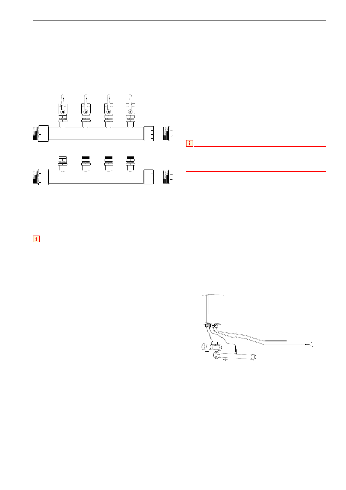
4.1 Brine Circuit Manifold
The brine circuit manifold merges the individual collector loops of
the heat source system into a single main pipe which is con-
nected to the heat pump. Integrated ball valves allow the individ-
ual brine circuits to be shut off for de-aeration purposes.
4.2 Remote control
A remote control adds convenience and is available as a special
accessory. Operation and menu navigation are identical to those
of the heat pump manager. Connection is made using a 6-core
telephone cable (special accessory) with modular plugs.
NOTE
In the case of heating controllers with a removable operating element,
this can also be used directly as a remote control.
4.3 Building management
technology
The heat pump manager can be connected to a building man-
agement system network via supplementation of the relevant in-
terface plug-in card. The supplementary installation instructions
of the interface card must be consulted regarding the exact con-
nection and parameterisation of the interface.
The following network connections can be made on the heat
pump manager:
Modbus
EIB, KNX
Ethernet
4.4 Thermal energy meter WMZ
4.4.1 General description
The thermal energy meter (WMZ 25/32) is used for measuring
the quantity of thermal energy supplied. It is available as an ac-
cessory. Due to the additional heat exchanger, two thermal en-
ergy meters are required for measuring the quantity of thermal
energy.
Sensors in the flow and return of the heat exchanger pipes and
an electronics module acquire the measured values and transmit
a signal to the heat pump manager, which, depending on the cur-
rent operating mode of the heat pump (heating/DHW/swimming
pool), totals the thermal energy in kWh and displays them in the
operating data and history menu.
NOTE
The thermal energy meter complies with the quality requirements of the
German market incentive programme subsidising efficient heat pumps.
The thermal energy meter is not subject to obligatory calibration, and can
thus not be used for the heating cost billing procedure!
4.4.2 Hydraulic and electrical integration
of the thermal energy meter
The thermal energy meter requires two measuring devices for
data acquisition.
A measuring tube for the flow measurement
This must be installed in the heat pump flow (observe flow
direction).
A temperature sensor (copper pipe with immersion sleeve)
This must be installed in the heat pump return.
The installation locations for both measuring tubes should be as
close to the heat pump as possible in the generator circuit.
To avoid eddying effects which could lead to incorrect measure-
ments, there should be a gap of 50 cm between the measuring
devices and other installed components such as pumps or
valves.
/13(
9+]
1,';
9$&
7KHUPDOHQHUJ\PHWHUFDVLQJHOHFWURQLFV
LQWKHKHDWLQJIORZ
LQWKHKHDWLQJUHWXUQIORZ
3XOVHWKHUPDOHQHUJ\PHWHU
Loading ...
Loading ...
Loading ...