Loading ...
Loading ...
Loading ...
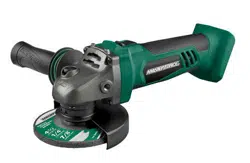
ADJUST THE GUARD (FIG. 4)
WARNING:
Failure to remove the
battery pack from the cordless angle grinder
when assembling parts, making adjust-
ments, or changing application tools could
result in accidental starting and cause seri-
ous injury.
1. Remove the battery pack from the
angle grinder
2. Press the guard-adjusting lever, and hold
it to loosen the guard.
3. Rotate the guard to the desired position
and make sure that the lever lines up with
notches on the guard.
4. Release the guard-adjusting lever to lock the
guard; verify that the lever secures the guard.
WARNING:
ALWAYS use the guard
when grinding with a grinding wheel. It has
been designed for use only with the guard
attached. Attempting to use the grinder
with the guard removed will result in loose
particles being thrown against the opera-
tor and possibly serious personal injury.
WARNING:
Only use the guard with
grinding wheels. Make sure that the guard-
adjusting lever secures the guard before
operation. Keep the guard between you
and wheel. Do not direct the guard open-
ing towards your body.
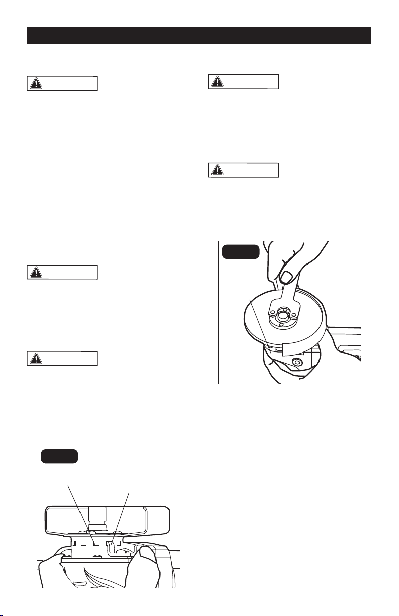
MOUNTING THE WHEEL (FIG. 5-6)
WARNING:
Only use grinding wheels
for which the maximum safe operating speed
is rated at or above 13200 RPM. Never use
damaged or imbalanced grinding wheels.
Do not exceed the recommended wheel
diameter. Grinding wheel type 27 is recom-
mended for use on this grinder.
WARNING:
Failure to remove the
battery pack from the cordless angle
grinder when assembling parts, making
adjustments, or changing application tools
could result in accidental starting and
cause serious injury.
FIG. 5
Spindle-lock
button
1. Remove the battery pack from the
angle grinder.
2. Make sure that the guard is securely in
place. Depress and hold the spindle-lock
button. Loosen the outer flange with the
supplied wrench while holding the spindle-
lock button down (FIG. 5).
3. Place the inner flange on the spindle;
make sure that the flange is positioned so
that the shape of the opening in the flange
corresponds with the shape at the base of
the spindle.
4. Place the grinding wheel on the spindle.
Check the rated speed on the grinding
wheel. DO NOT use a wheel with a rated
speed lower than the speed shown on the
grinder nameplate.
Page 12
OPERATION
FIG. 4
Guard-adjusting
lever
Notch on the
guard
Loading ...
Loading ...
Loading ...