Before using your new product, please read these instructions to prevent any damage.
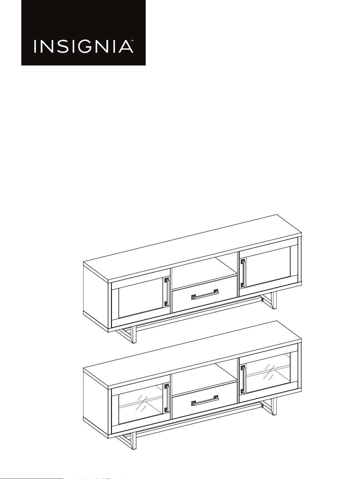
ASSEMBLY GUIDE
Console for TVs
up to 80”
NS-HFMS80
www.insigniaproducts.com
2
Contents
IMPORTANT SAFEGUARDS . . . . . . . . . . . . . . . . . . . . . . . . . . . . . . . . . . . . . . . . . . . . . . . . . . . . . . . . . . . . . . . . . . . . . . . . . . . . 3
Features . . . . . . . . . . . . . . . . . . . . . . . . . . . . . . . . . . . . . . . . . . . . . . . . . . . . . . . . . . . . . . . . . . . . . . . . . . . . . . . . . . . . . . . . . . . . . . 4
Dimensions. . . . . . . . . . . . . . . . . . . . . . . . . . . . . . . . . . . . . . . . . . . . . . . . . . . . . . . . . . . . . . . . . . . . . . . . . . . . . . . . . . . . . . . . . . . . . . . . . . . . . . . 4
Package contents . . . . . . . . . . . . . . . . . . . . . . . . . . . . . . . . . . . . . . . . . . . . . . . . . . . . . . . . . . . . . . . . . . . . . . . . . . . . . . . . . . . . . 5
Parts . . . . . . . . . . . . . . . . . . . . . . . . . . . . . . . . . . . . . . . . . . . . . . . . . . . . . . . . . . . . . . . . . . . . . . . . . . . . . . . . . . . . . . . . . . . . . . . . . . . . . . . . . . . . . 5
Hardware. . . . . . . . . . . . . . . . . . . . . . . . . . . . . . . . . . . . . . . . . . . . . . . . . . . . . . . . . . . . . . . . . . . . . . . . . . . . . . . . . . . . . . . . . . . . . . . . . . . . . . . . . 6
Tools needed . . . . . . . . . . . . . . . . . . . . . . . . . . . . . . . . . . . . . . . . . . . . . . . . . . . . . . . . . . . . . . . . . . . . . . . . . . . . . . . . . . . . . . . . . 7
Installation tips . . . . . . . . . . . . . . . . . . . . . . . . . . . . . . . . . . . . . . . . . . . . . . . . . . . . . . . . . . . . . . . . . . . . . . . . . . . . . . . . . . . . . . . 7
Assembling your stand. . . . . . . . . . . . . . . . . . . . . . . . . . . . . . . . . . . . . . . . . . . . . . . . . . . . . . . . . . . . . . . . . . . . . . . . . . . . . . . . 8
Maintaining your TV console . . . . . . . . . . . . . . . . . . . . . . . . . . . . . . . . . . . . . . . . . . . . . . . . . . . . . . . . . . . . . . . . . . . . . . . . .35
Specifications. . . . . . . . . . . . . . . . . . . . . . . . . . . . . . . . . . . . . . . . . . . . . . . . . . . . . . . . . . . . . . . . . . . . . . . . . . . . . . . . . . . . . . . .35
ONE-YEAR LIMITED WARRANTY . . . . . . . . . . . . . . . . . . . . . . . . . . . . . . . . . . . . . . . . . . . . . . . . . . . . . . . . . . . . . . . . . . . . . .36
www.insigniaproducts.com
3
Console for TVs up to 80”
IMPORTANT SAFEGUARDS
WARNING
CAUTION
The top surface of this stand is designed for use with a product weighing no more than 135 lbs. (61.2 kg) and having a
width that permits it to sit evenly on the stand with no more than a one-inch overhang on each side of the shelf. Use
with products that weigh more than the maximum weight allowed, or with dimensions that extend beyond the
maximum width may result in instability, which may result in injury.
CAUTION
The drawer weight capacity of this product is 30 lbs. (13.6 kg).
CAUTION
This product contains small items that could be a choking hazard if swallowed. Keep these items away from young
children!
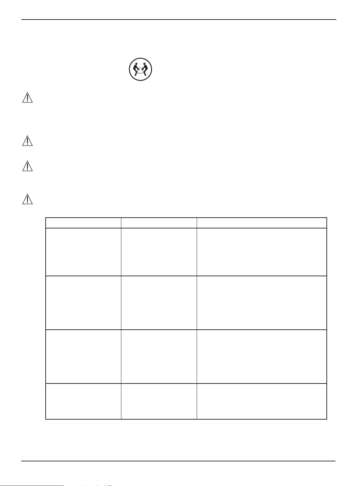
WARNING
Please use your stand correctly and safely. Improper use can cause safety hazards or damage to your furniture or
household items. Carefully read the following chart.
SAVE THESE INSTRUCTIONS
LOOK OUT FOR: WHAT CAN HAPPEN: HOW TO AVOID THE PROBLEM:
• Children climbing on the
stand.
• A child may try to reach a
toy or other object by
climbing on the stand.
• Children will play and be
active near the TV.
• Risk of injury or death.
• A child climbing on the
stand can make it
top-heavy and cause it to
tip over.
• A child playing with a TV
can cause it to tip over.
• Never allow children to climb on or play with
the stand.
• Do not place toys or food on the top shelves.
Children may try to climb to reach them out of
curiosity.
• Improper use of the stand
to support TVs.
• The stand is designed for
use with TVs will specify
the maximum weight
rating and recommended
size of the TVs it will safely
support.
• Risk of injury or death.
• TVs can be very heavy.
Note, older CRT TVs tend
to be unbalanced and
prone to tipping forward.
• A TV must only be set on furniture specifically
designed to support a television.
• Never use a TV that exceeds the weight ratings
or size guidelines specified for the stand.
• Improperly moving the
stand.
• The stand can tip over or
break if improperly
moved.
• Risk of injury.
• Unload shelves from the top to the bottom
before moving the stand.
• Do not push the stand, especially on a carpeted
floor. Have a friend help you lift the item and set
it in place.
• Do not lift the stand using the top shelf. Lift
from the frame or leg assembly.
• Remove the TV before moving the TV stand.
• The TV/stand assembly
tipping forward.
• Risk of injury.
• Top-heavy furniture can
tip over.
• The TV and stand could
be damaged.
• Use the tipping restraint hardware provided
and install it properly.
Some steps are more easily
handled with two adults.
www.insigniaproducts.com
4
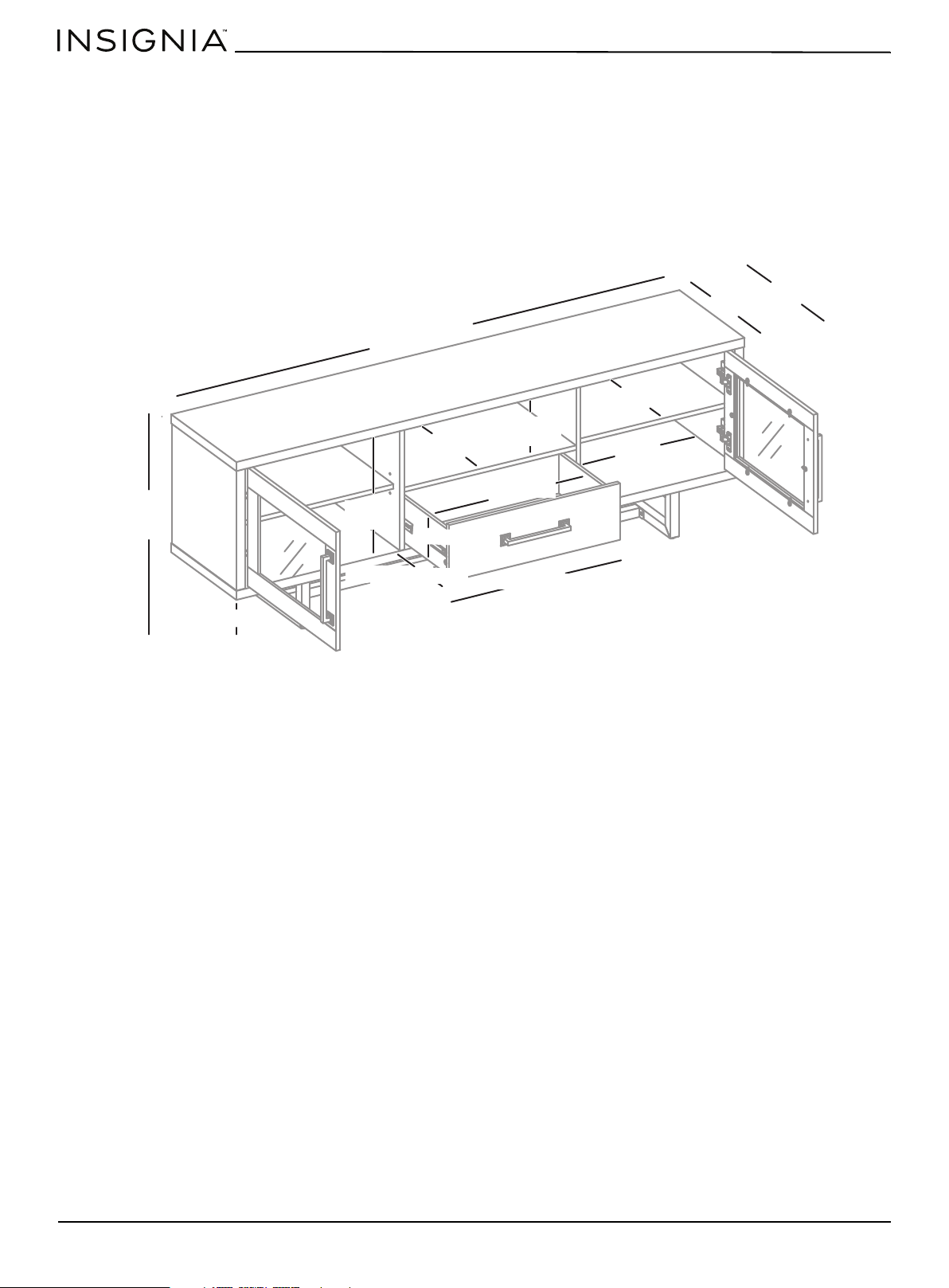
Features
• Interchangeable door fronts customize your stand’s look with either glass or wood insert panels
• Sturdy frame supports most flat screen TVs up to 80 in. (203.2 cm) and 135 lbs (61.2 kg)
• Shelving adds space for cable boxes, Blu-ray players, game consoles, and more
• Drawer stores cords, spare remotes and other accessories out of sight
• Light gray wood finish with metal accents looks modern to match most decor
• Cutouts leave room for cords to exit the back while ventilating electronics
Dimensions
70 in. (177.8 cm)
24.3 in.
(61.6 cm)
15.9 in.
(40.4 cm)
16.6 in. (42.3 cm)
13.5 in. (34.5 cm)
22 in.
(55.8 cm)
14.8 in. (37.7 cm)
7.7 in.
(19.6 cm)
21.7 in. (55.2 cm)
15.6 in. (39.5 cm)
23.7 in. (60.2 cm)
6.1 in. (15.6 cm)
12.5 in. (31.7 cm)
6.5 in. (16.5 cm)
www.insigniaproducts.com
5
Console for TVs up to 80”
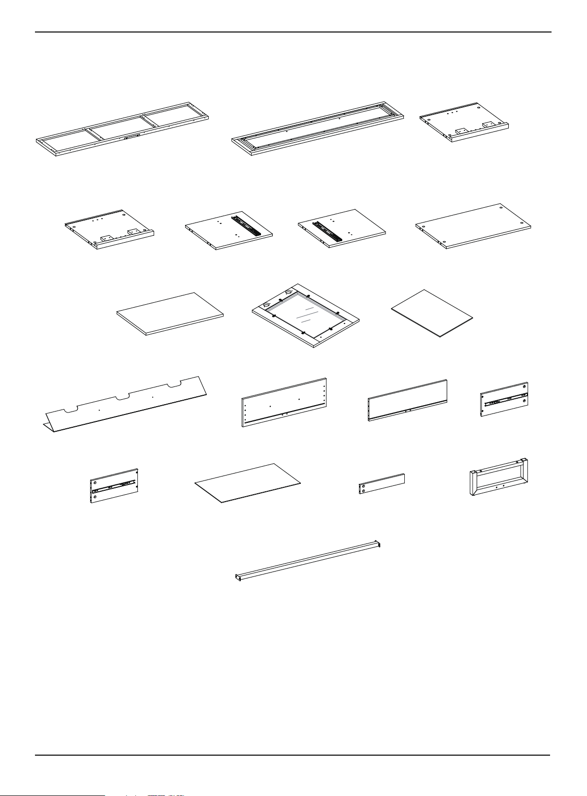
Package contents
Make sure that you have all the parts necessary to assemble your new TV stand.
Parts
A Top panel (1)
Note: Keep the stopper template attached to the top
panel
B Bottom panel (1) C Left side panel (1)
D Right side panel (1) E Left partition panel (1) F Right partition panel (1) G Media Shelf (1)
H Adjustable shelf (2) I Door (2) J Wood door panel (2)
K Back panel (1)
L Drawer front panel (1) M Drawer back panel (1) N Drawer left side panel (1)
P Drawer right side panel (1) Q Drawer bottom panel (1) R Drawer bottom support (1) S Metal base (2)
T Metal stretcher (1)
www.insigniaproducts.com
6
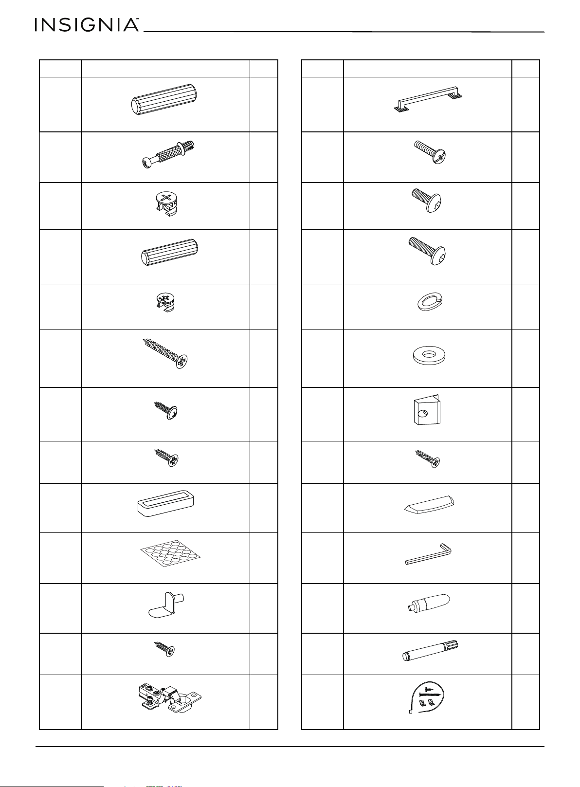
Hardware
LABEL STAND PART QTY. LABEL STAND PART QTY.
U 20 HH 3
V 26 II 6
W 20 JJ 4
X 8 KK 4
Y 6 LL 8
Z 6 MM 8
AA 4 NN 8
BB 4 PP 8
CC 2 QQ 2
DD 16 RR 1
EE 8 SS 1
FF 8 TT 1
GG 4 UU 2
Wood dowel M8 x 30 mm
Handle
Cam pin
Handle bolt
Large cam lock
Bolt 1/4” x 5/8”
Wood dowel M6 x 30 mm
Bolt 1/4” x 1-1/4”
Small cam lock
Lock washer
Flat head screw M4 x 38 mm
Flat washer
Washer head screw M3.5 x 15 mm
Plastic holder
Flat head screw M3.5 x 15 mm
Flat head screw M3 x 17 mm
Door stopper
Acrylic stopper
PVC cover
4 mm hex wrench
Shelf support
Glue
Zinc hinge screw M4 x 14 mm
Touch-up pen
Hinge
Tipping restraint hardware kit
www.insigniaproducts.com
7
Console for TVs up to 80”
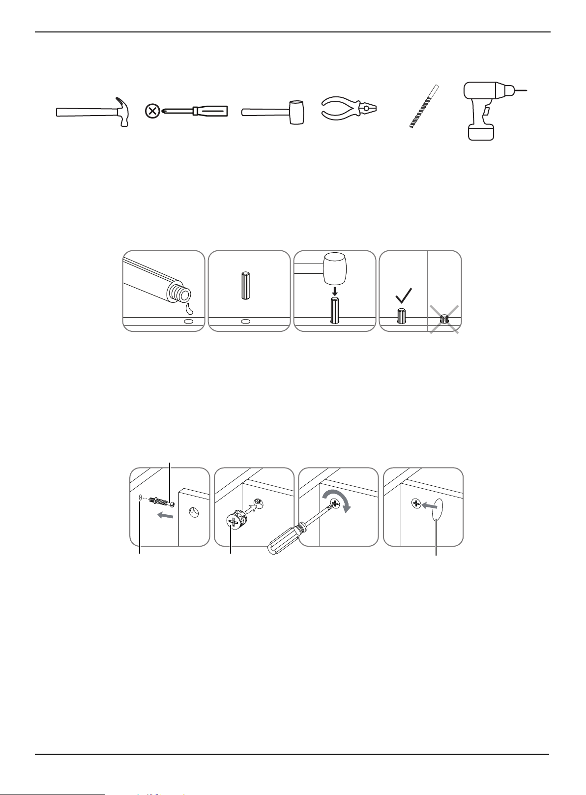
Tools needed
Installation tips
Gluing wood dowels (U and X)
When using a wood dowel (U and X), put one drop of glue (SS) in the hole before you insert the wood dowel (U and X).
Insert the wood dowel (U and X), then gently tap it with a rubber mallet to secure it in place.
Locking cam pins (V) and cam locks (W and Y)
1 One end of a cam pin (V) is threaded so that it screws into place. The other end is not threaded. Before you insert the
un-threaded end into a hole, insert a cam lock (W and Y) into the hole and make sure that the hole in the cam lock (W
and Y) faces the outside edge of the part being used.
2 Insert the un-threaded end of the cam pin (V) through the hole in the part being used and into the cam lock hole, then
rotate the cam lock (W and Y) clockwise with a screwdriver to lock the cam pin (V) into place.
3 Insert a PVC cover (DD) into the cross slot of the cam lock (W and Y) to conceal.
Phillips screwdriver
Hammer
1/8” drill bit
Power drill
Rubber mallet
Pliers
312 4
GL
U
E
PAN E L
Cam pin
Pre-drilled hole
Cam lock
Locked panel
PVC cover
www.insigniaproducts.com
8
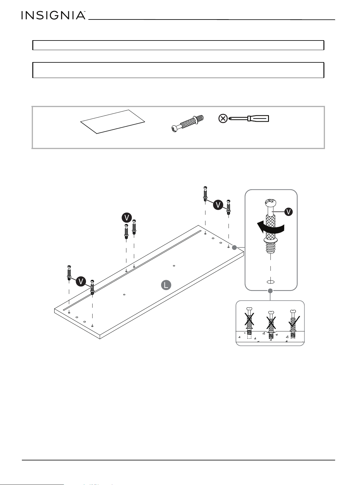
Assembling your stand
STEP 1: Screw cam pins onto the drawer front panel
You nee d :
• Securely screw the cam pins (V) into the indicated holes in the drawer front panel (L), using a Phillips screwdriver.
Tip: Assemble your stand on a carpeted floor or the empty TV stand box to avoid scratching it.
Note: Do not fully tighten all bolts until you finish assembling all of the parts. After assembly, go back and fully
tighten all bolts. This will make the assembly easier.
L Drawer front panel (1)
V Cam pin (6)
Phillips screwdriver
Metal frame
www.insigniaproducts.com
9
Console for TVs up to 80”
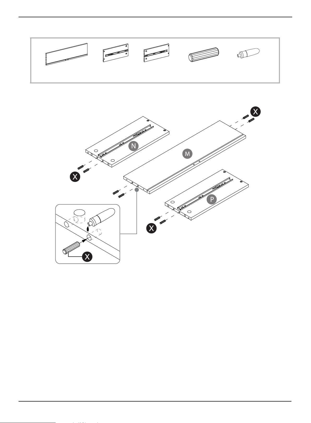
STEP 2: Install the small wood dowls
You n ee d :
• Glue eight small wood dowels (X) into the drilled holes on the ends of the drawer back panel (M) and drawer side
panels (N and P).
M Drawer back panel (1)
SS Glue (1)
X Wood dowel (8)
N Drawer left side
panel (1)
P Drawer right
side panel (1)
www.insigniaproducts.com
10
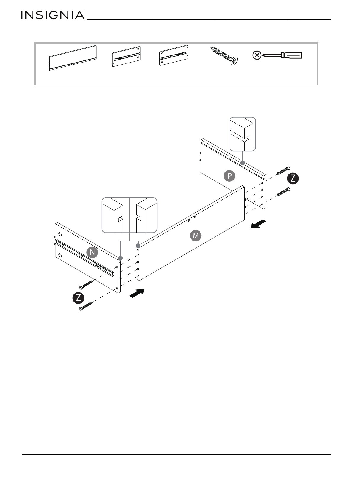
STEP 3: Assembly the drawer back panel and the drawer side panels
You n ee d :
• Attach the drawer back panel (M) between the drawer side panels (N and P) with four 38 mm screws, using a Phillips
screwdriver. The grooves in the drawer panels must line up with each other and face inward.
Z 38 mm screws (4)
M Drawer back panel (1)
N Drawer left side
panel (1)
P Drawer right
side panel (1)
Phillips screwdriver
Metal frame
www.insigniaproducts.com
11
Console for TVs up to 80”
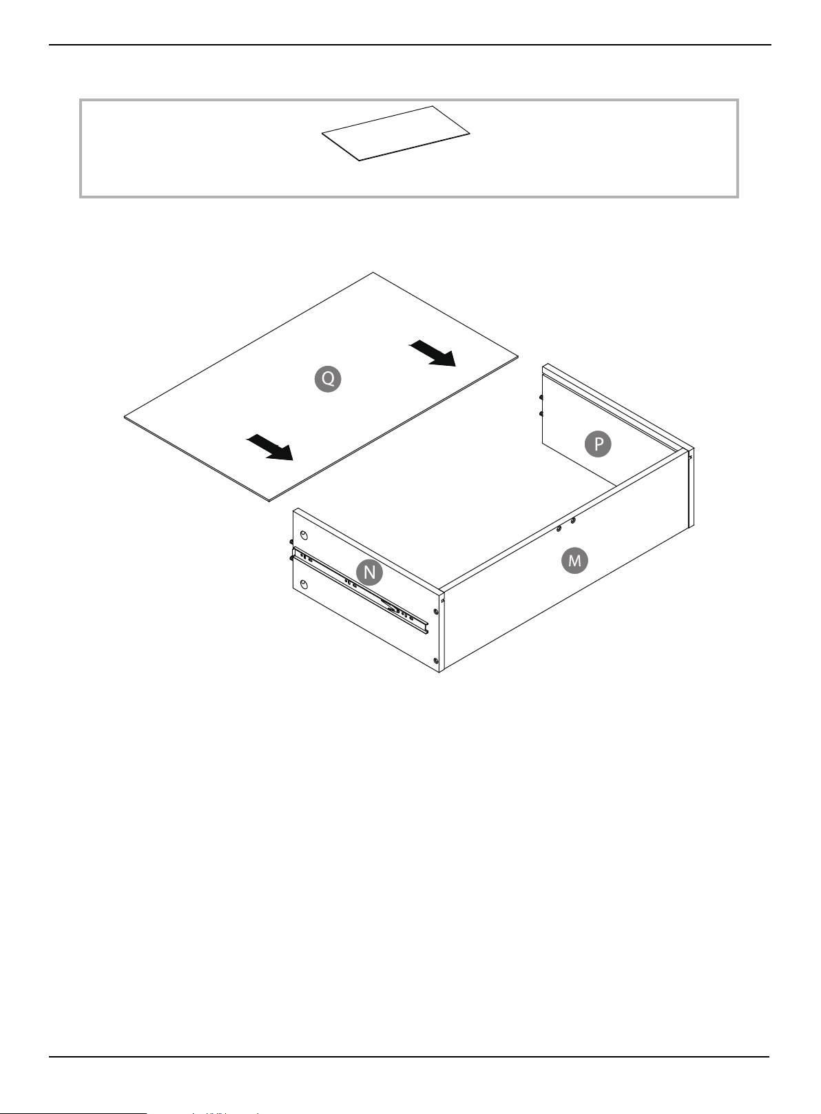
STEP 4: Install the drawer bottom panel
You n ee d :
• Slide the drawer bottom panel (Q) into the drawer assembly (N, P, and M) until fully inserted.
Q Drawer bottom panel (1)
www.insigniaproducts.com
12
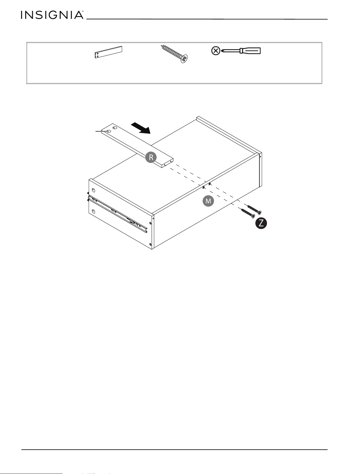
STEP 5: Install the drawer bottom support
You n ee d :
• Fasten the drawer bottom support (R) to the drawer back panel (M) with two 38 mm screws (Z). The cam screw holes
should face upward.
Z 38 mm screw (2)
R Drawer bottom support (1)
Phillips screwdriver
Cam screw holes
www.insigniaproducts.com
13
Console for TVs up to 80”
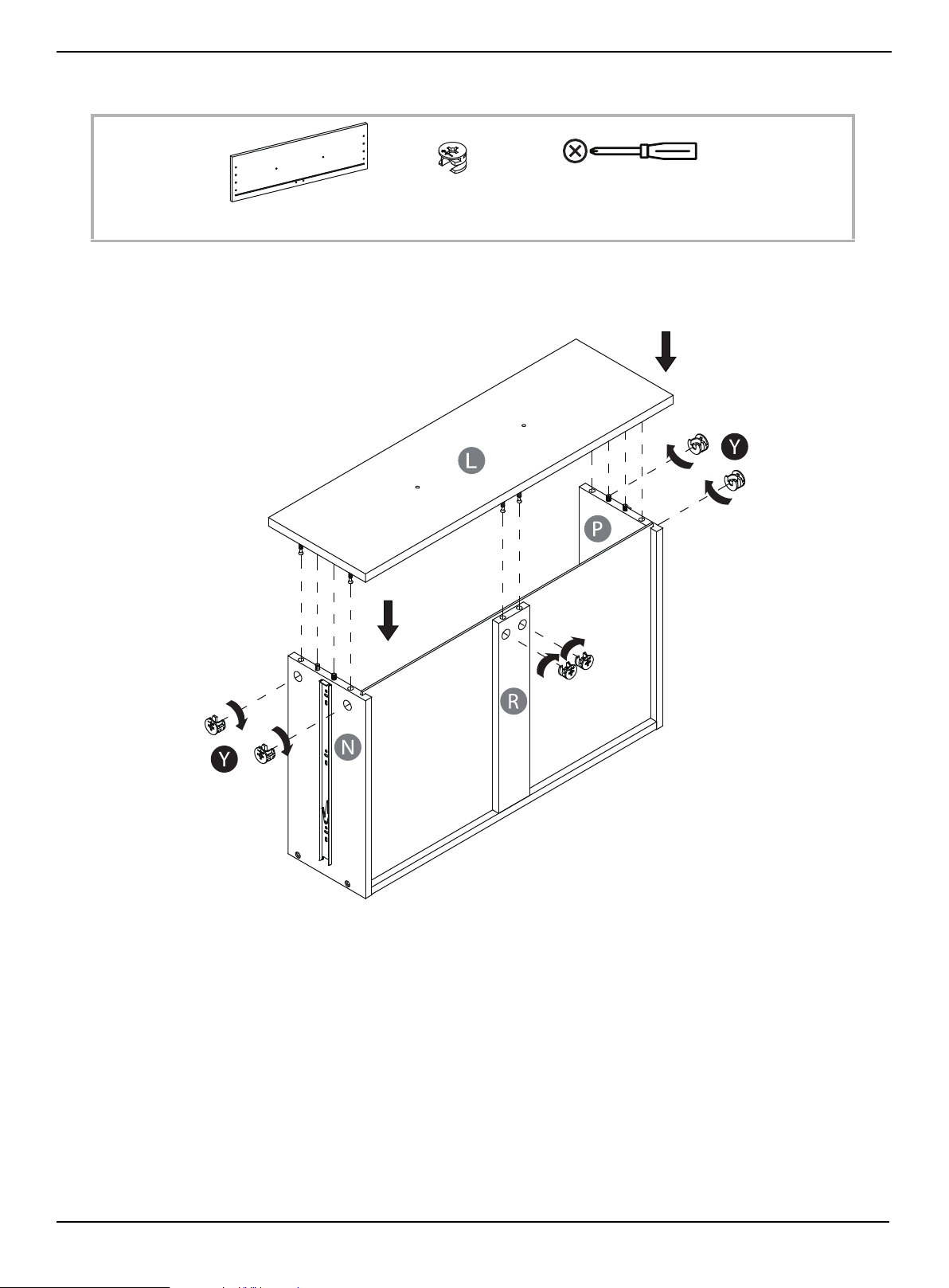
STEP 6: Install the drawer front
You n ee d :
• Stand the drawer assembly on its back and position the drawer front panel (L) onto the installed wood dowels. Fasten
the drawer front panel in place with the small cam locks (Y).
Y Small cam locks (6)
L Drawer front panel (1)
Phillips screwdriver
www.insigniaproducts.com
14
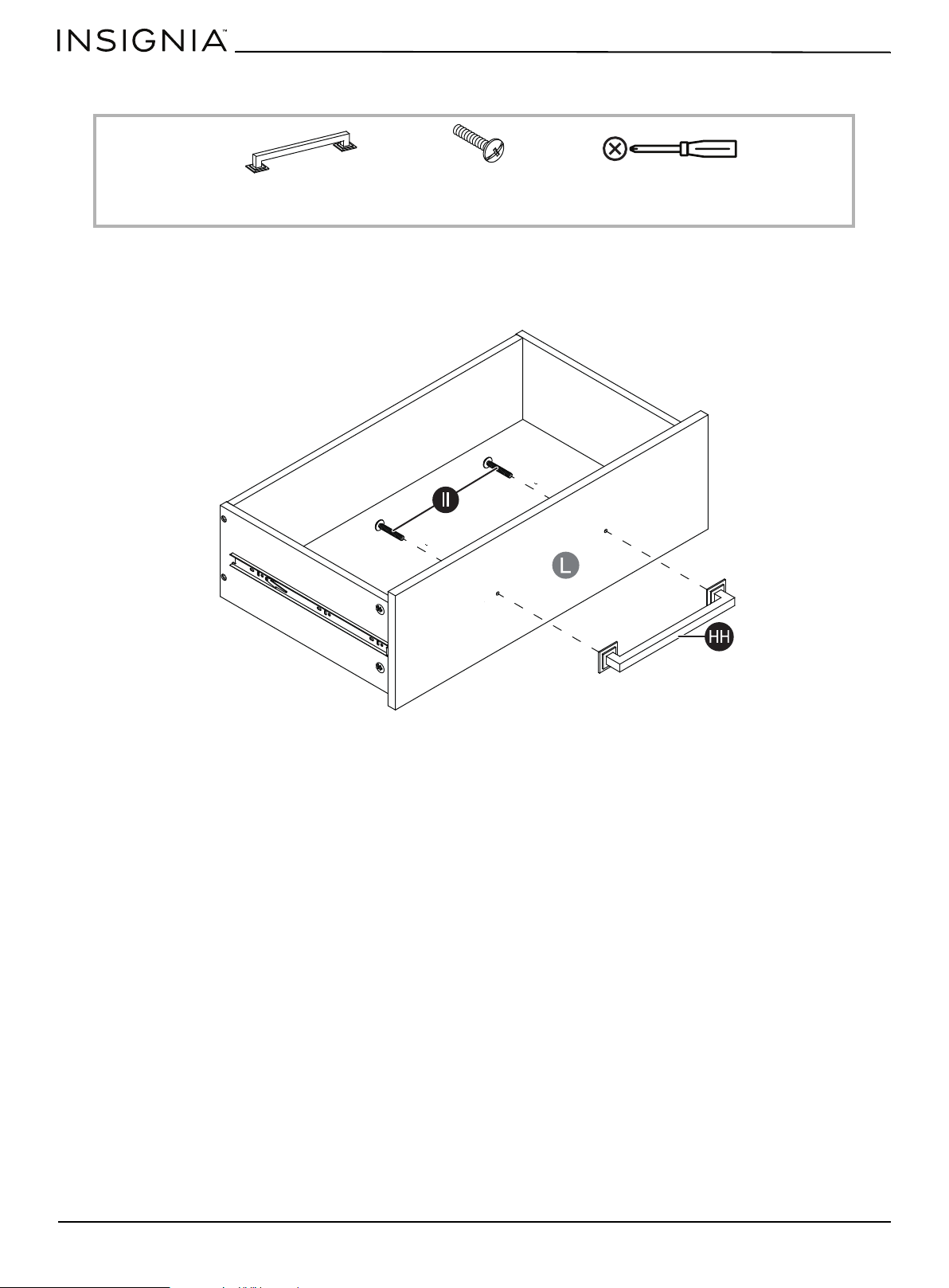
STEP 7: Install the drawer handle
You n ee d :
• Turn the drawer assembly upright and attach the drawer handle (HH) to the front of the drawer assembly with two
handle bolts (II).
HH Drawer handle (1)
II Handle bolts (2)
Phillips screwdriver
www.insigniaproducts.com
15
Console for TVs up to 80”
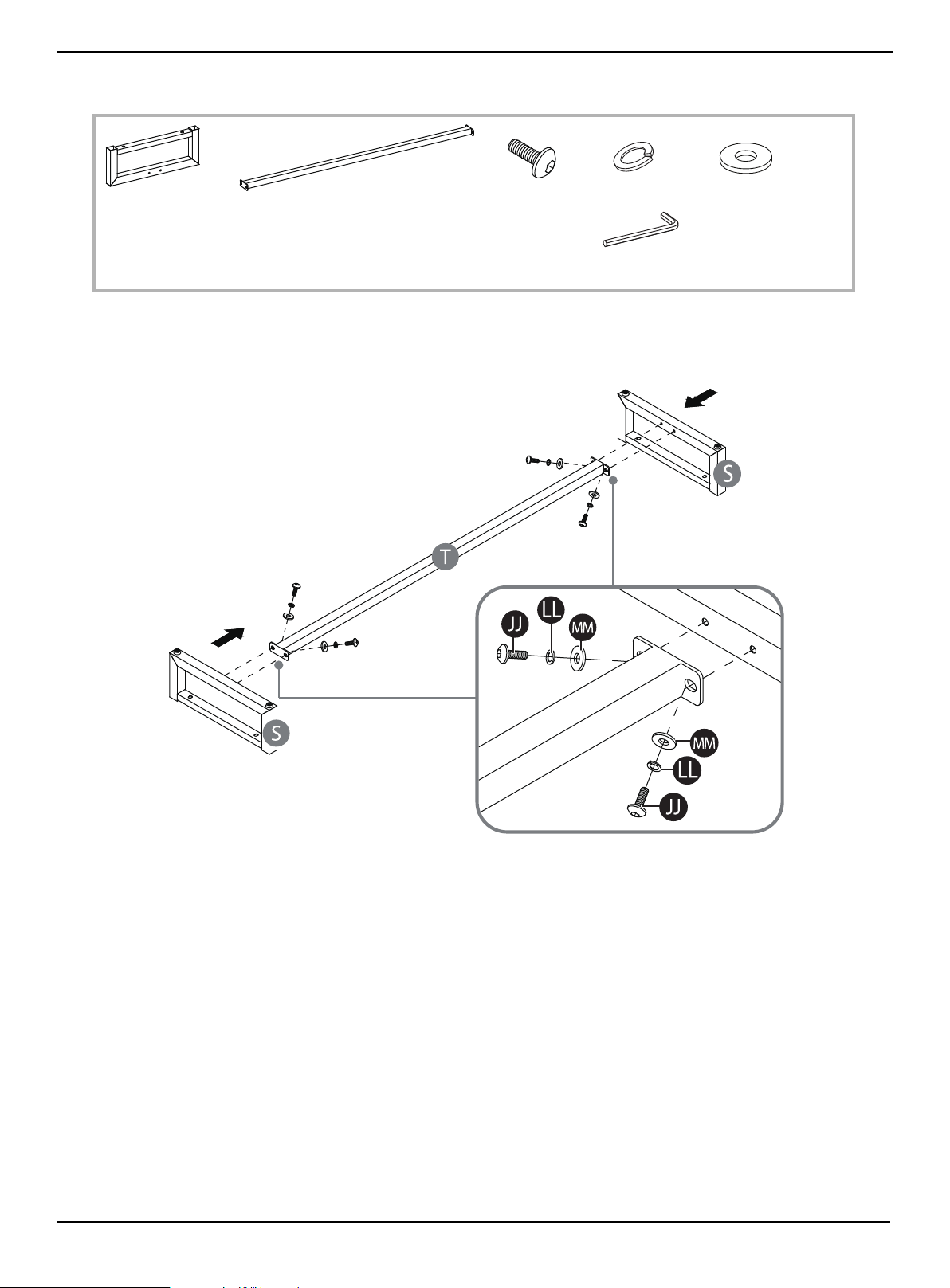
STEP 8: Assembling the metal base
You n ee d :
• Insert four 5/8” bolts (JJ) with four lock washers (LL) and flat washers (MM) through the holes in the metal stretcher (T),
into the metal bases (S), then tighten the bolts with the 4 mm hex wrench (RR).
RR Hex wrench 4 mm (1)
LL Lock washer (4)
MM Flat washer (4)
S Metal base (2)
T Metal stretcher (1)
JJ 5/8” bolt (4)
www.insigniaproducts.com
16
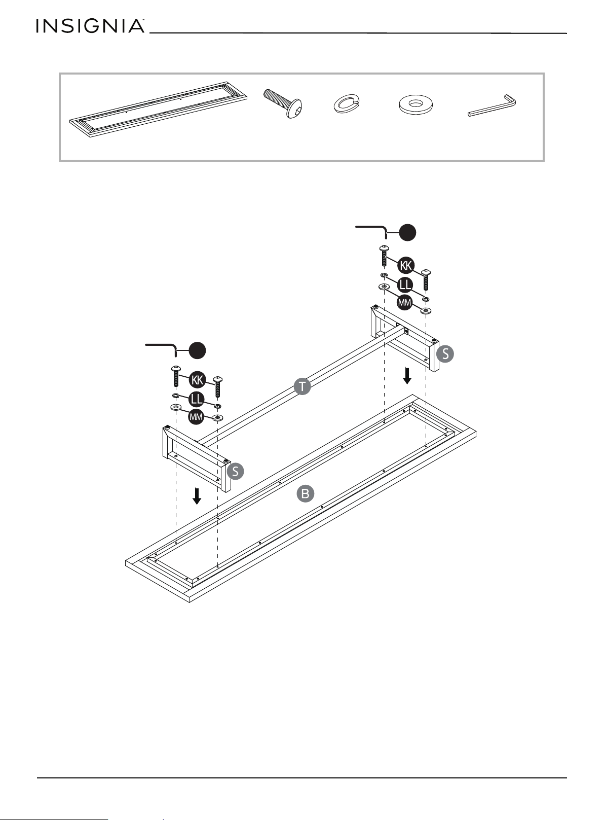
STEP 9: Attach the metal base to the bottom panel
You n ee d :
• Insert four 1/1/4” bolts (KK) with lock washers (LL) and flat washers (MM) through the holes on both bases (S), then
tighten them into the threaded holes in the bottom panel (B) with the 4 mm hex wrench.
RR Hex key 4 mm (1)
LL Lock washer (4)
MM Flat washer (4)
KK 1-1/4” bolt (4)
B Bottom panel (1)
RR
RR
www.insigniaproducts.com
17
Console for TVs up to 80”
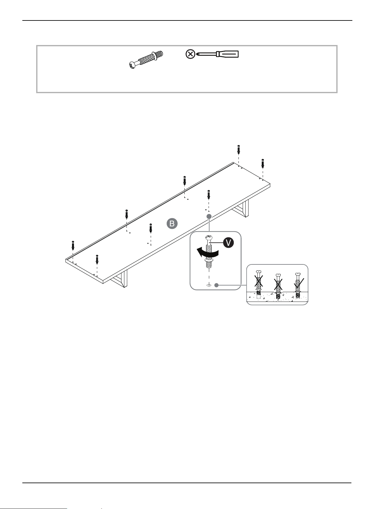
STEP 10: Prepare the bottom panel assembly
You n ee d :
• Securely screw eight cam pins (V) into the indicated small holes in the bottom panel assembly, using a Phillips
screwdriver.
V Cam pin (8)
Phillips screwdriver
www.insigniaproducts.com
18
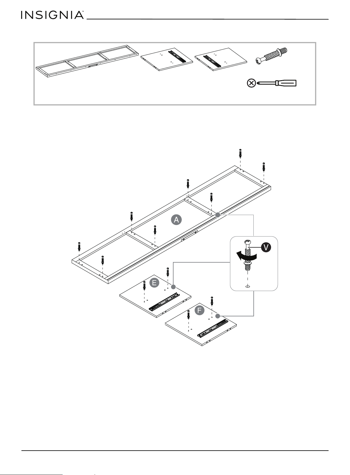
STEP 11: Prepare the top panel and partition panels
You n ee d :
• Securely screw twelve cam pins (V) into the indicated small holes in the top panel (A) and the partition panels (E and F)
with a Phillips screwdriver.
V Cam pin (12)
Phillips screwdriver
A Top panel (1)
E Left partition panel (1)
F Right partition panel (1)
www.insigniaproducts.com
19
Console for TVs up to 80”
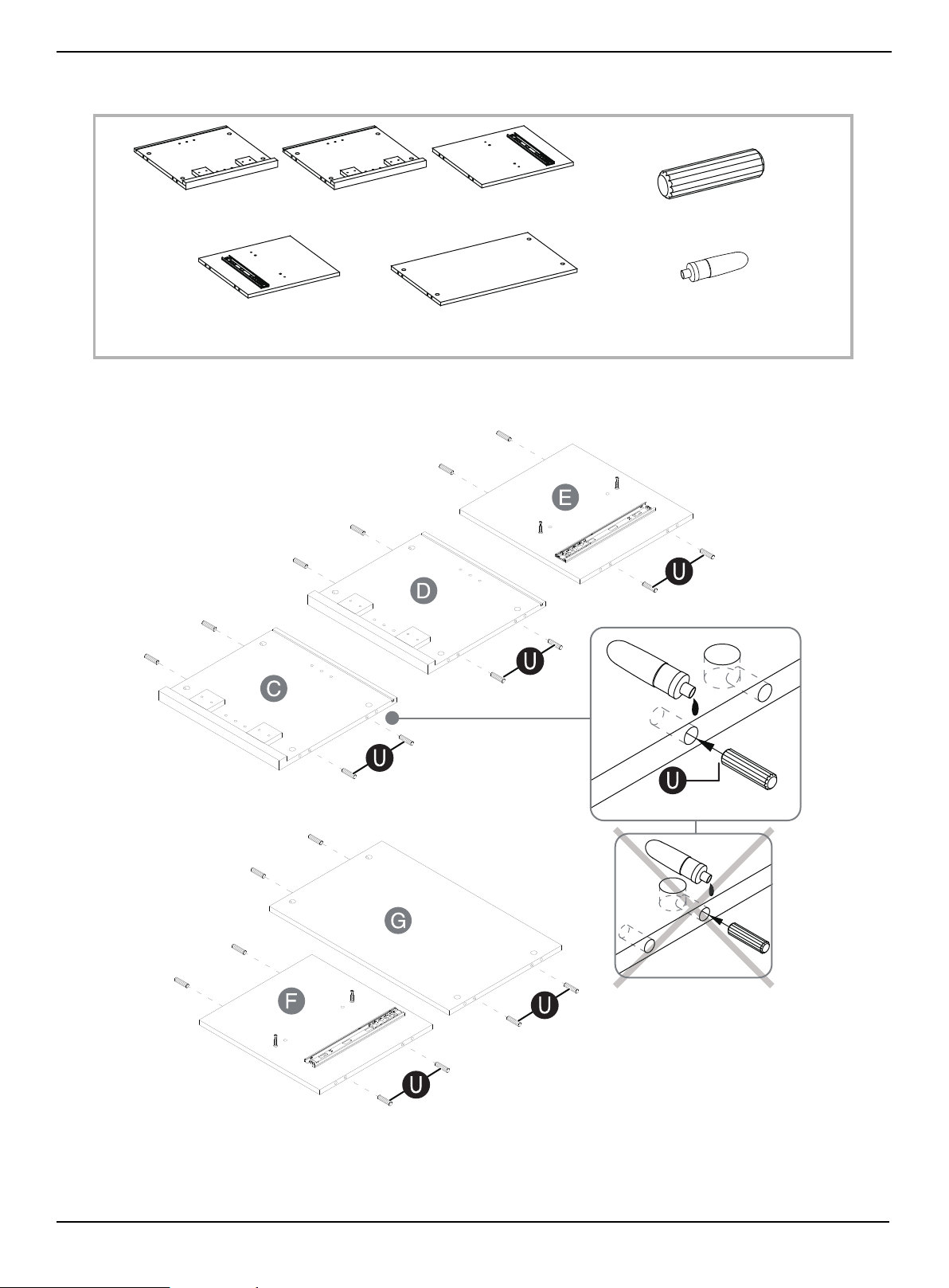
STEP 12: Prepare the side panels, partition panels, and media shelf
You n ee d :
• Glue the large wood dowels (U) into the drilled holes on both ends of the side panels (C and D), partition panels (E and
F), and media shelf (G).
U Wood dowel (20)
SS Glue (1)
C Left side panel (1) E Left partition panel (1)
F Right partition panel (1)
D Right side panel (1)
G Media shelf (1)
www.insigniaproducts.com
20
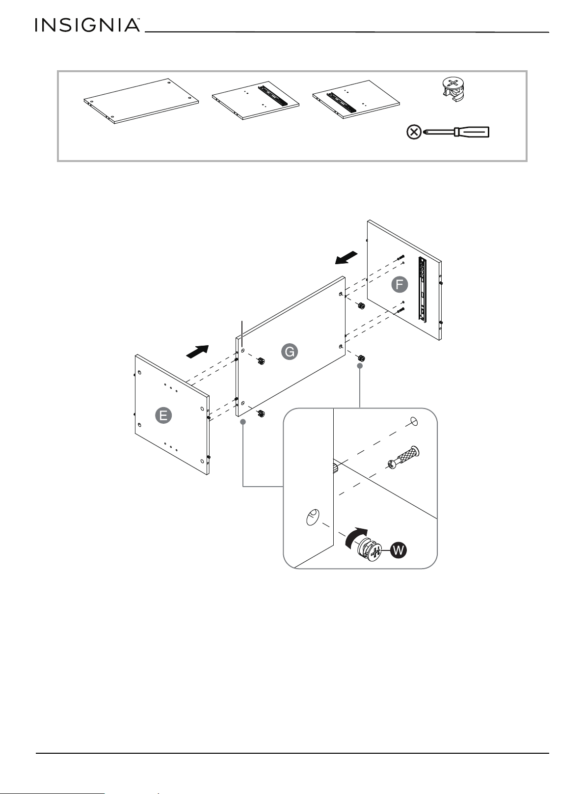
STEP 13: Attach the partition panels to the media shelf
You n ee d :
• Attach the media shelf (G) between the partition panels (E and F) by engaging four large cam locks (W). The cam screw
holes must face inward
W Large cam lock (4)
G Media shelf (1)
Phillips screwdriver
E Left partition panel (1)
F Right partition panel (1)
Cam screw holes
www.insigniaproducts.com
21
Console for TVs up to 80”
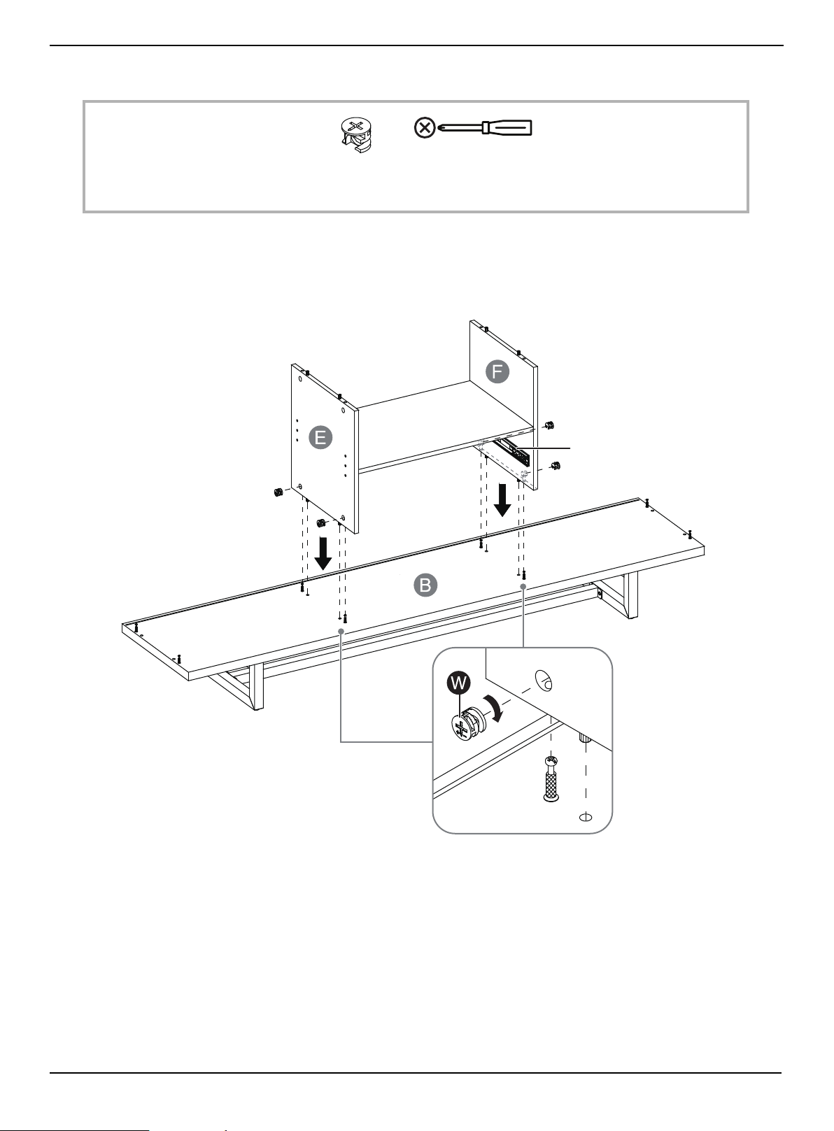
STEP 14: Install the media shelf
You n ee d :
• Install the media shelf assembly to the bottom assembly by engaging four large cam locks (W), using a Phillips
screwdriver. The drawer slide opening should face the front edge (without groove) of the bottom panel.
W Large cam lock (4)
Phillips screwdriver
The drawer slide opening
www.insigniaproducts.com
22
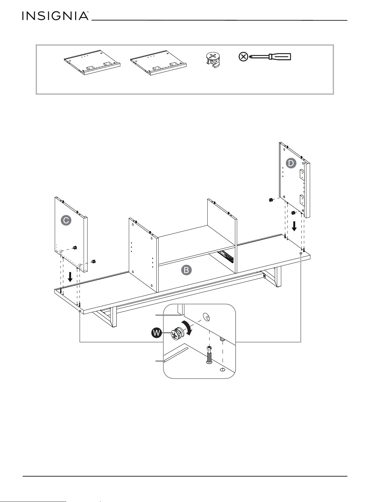
STEP 15: Attach the side panels
You n ee d :
• Attach the side panels (C and D) to the bottom assembly by engaging four large cam locks (W), using a Phillips
screwdriver. The grooves in the side panels should line up with the groove in the bottom panel.
W Large cam lock (4)
Phillips screwdriver
C Left side panel (1)
D Right side panel (1)
Groove
Groove
www.insigniaproducts.com
23
Console for TVs up to 80”
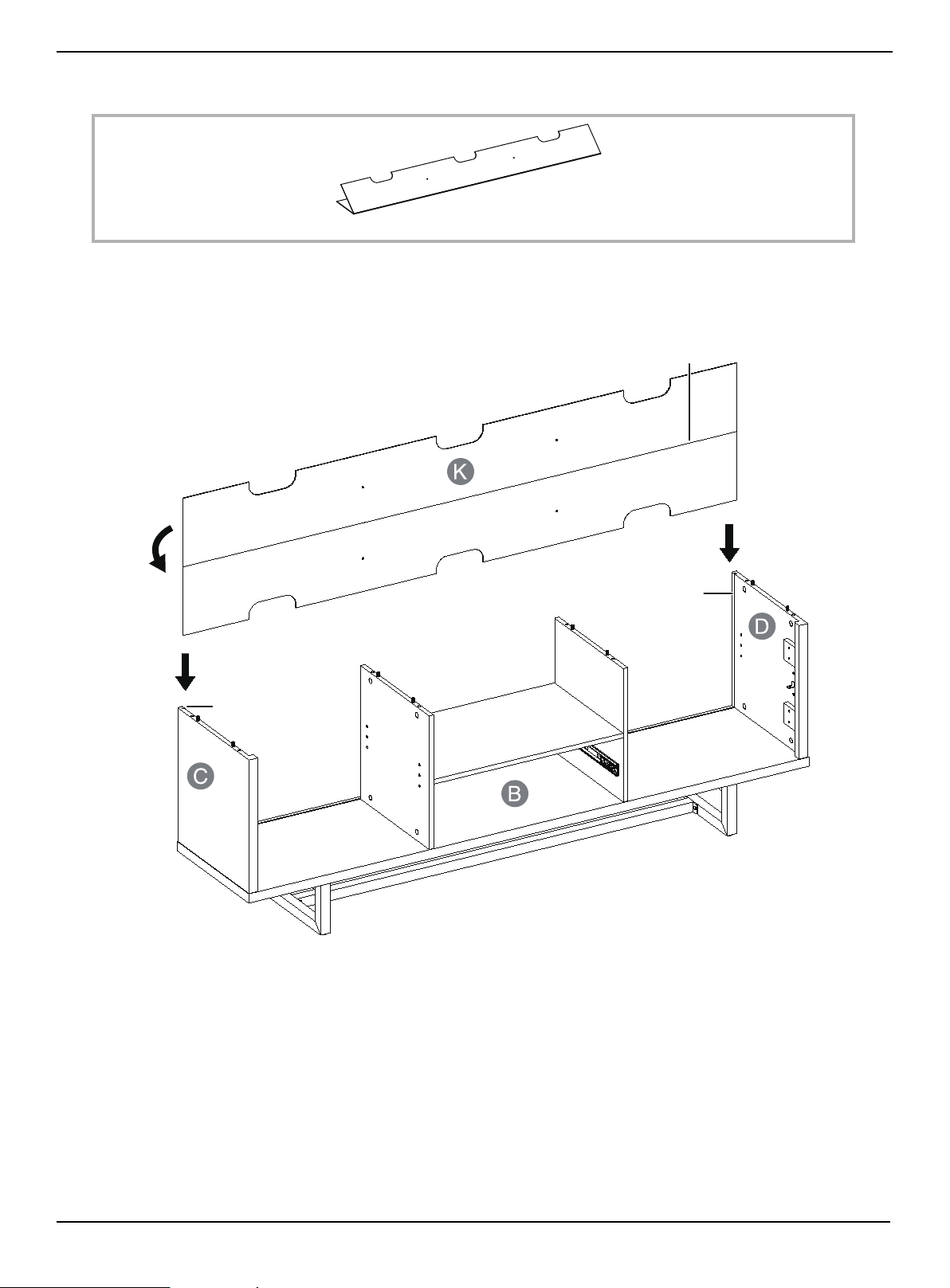
STEP 16: Install the back panel
You n ee d :
• Unfold the back panel (K), then slide it into the grooves on both side panels (C and D) until fully inserted into the
bottom panel assembly. Make sure that the adhesive tape faces backward.
K Back panel (1)
Adhesive tape
Groove
Groove
www.insigniaproducts.com
24
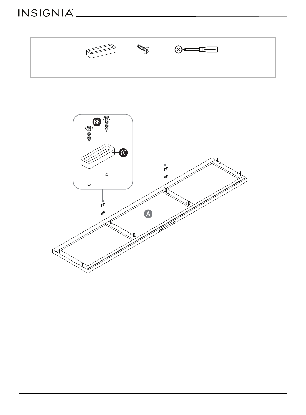
STEP 17: Install the door stoppers
You n ee d :
• Using the pilot holes as a guide, fasten two door stoppers (CC) to the top panel (A) with two 15 mm screws (BB) in each,
using a Phillips screwdriver.
CC Door stoppers (2)
BB 15 mm screws (4)
Phillips screwdriver

www.insigniaproducts.com
25
Console for TVs up to 80”
STEP 18: Install the top panel
You n ee d :
1 Using assistance, place the top panel (A) onto the wood dowels (U) on the vertical panels. Make sure that the back
panel (K) fits securely into the groove of the top panel (A).
2 Secure the top panel (A) into place by inserting eight large cam locks (W) and tightening them with a Phillips
screwdriver.
A Top panel (1)
Phillips screwdriver
W Large cam lock (8)
www.insigniaproducts.com
26
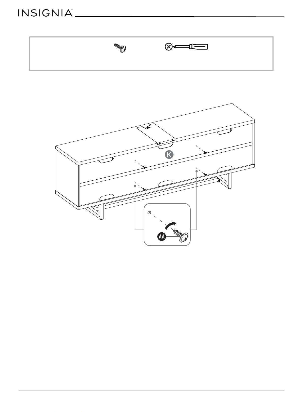
STEP 19: Secure the back panel to the partition panels
You n ee d :
• Insert four washer head screws (AA) through the holes in the back panel (K) and screw them into the partition panels
using a Phillips screwdriver.
Phillips screwdriver
AA Washer head screws (4)
www.insigniaproducts.com
27
Console for TVs up to 80”
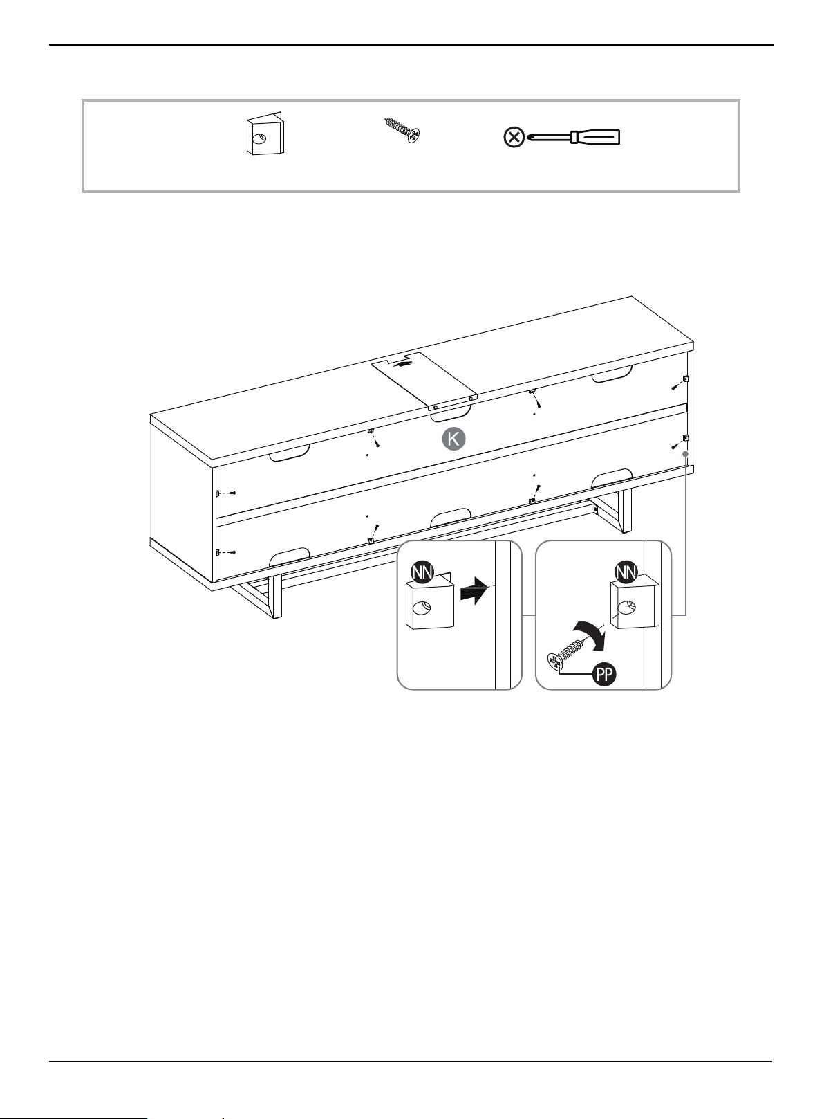
STEP 20: Fasten the back panel
You n ee d :
1 Insert eight plastic holders (NN) evenly into the gaps between the back panel (K) and frame panels (A, B, C and D) as
shown.
2 Secure the plastic holders into place with 17 mm screws (PP), using a Phillips screwdriver. Do not damage the edges.
Phillips screwdriver
PP 17 mm screws (8)
NN Plastic holders (8)
www.insigniaproducts.com
28
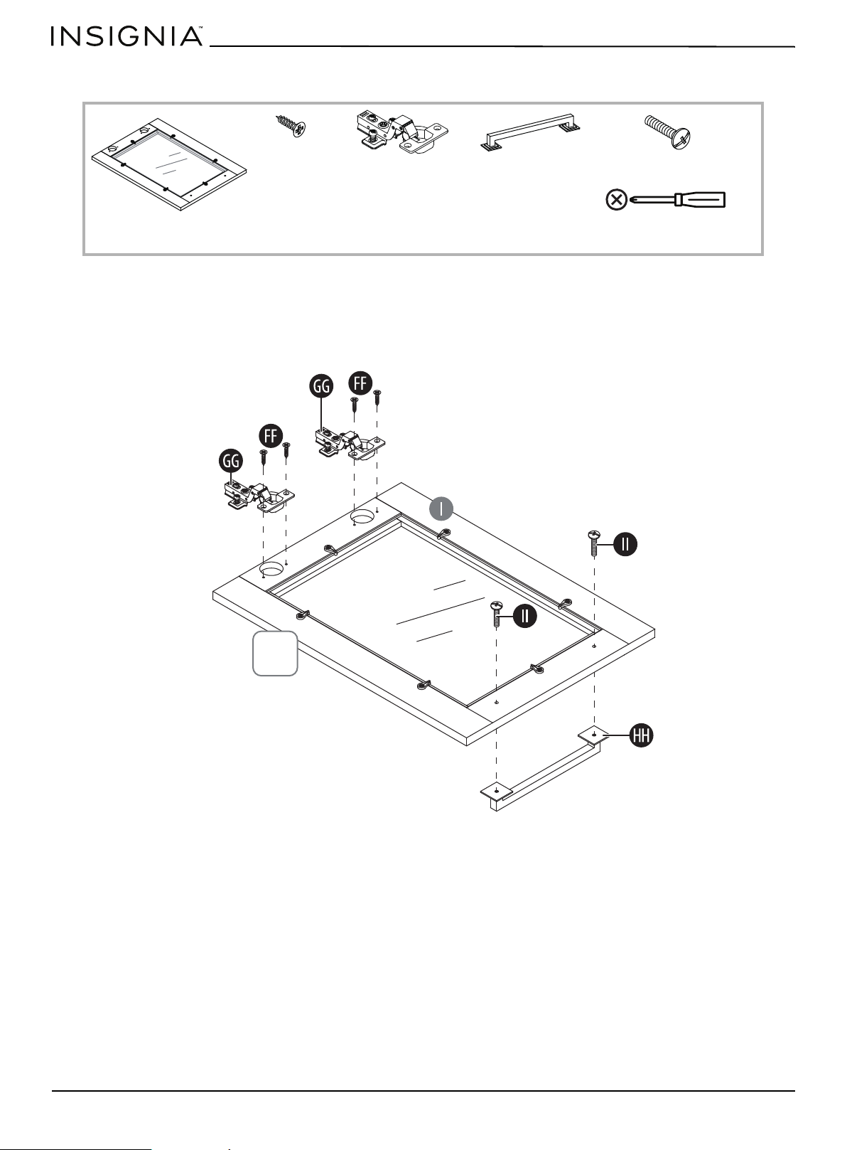
STEP 21: Install the door hinges and handles
You n ee d :
1 Extend two door hinges (GG) and rest the hinge cups onto the cutouts of each door (I). Secure the door hinges (GG) in
place by using two zinc screws (FF) for each.
2 Attach one handle (HH) to the front side of the door (I) with two handle bolts (II).
3 Complete this step once again to assemble the other door (I).
Phillips screwdriver
GG Hinges (4)
FF Zinc screws (8)
HH Handles (2)
II Handle bolts (4)
I Door (2)
x2
www.insigniaproducts.com
29
Console for TVs up to 80”
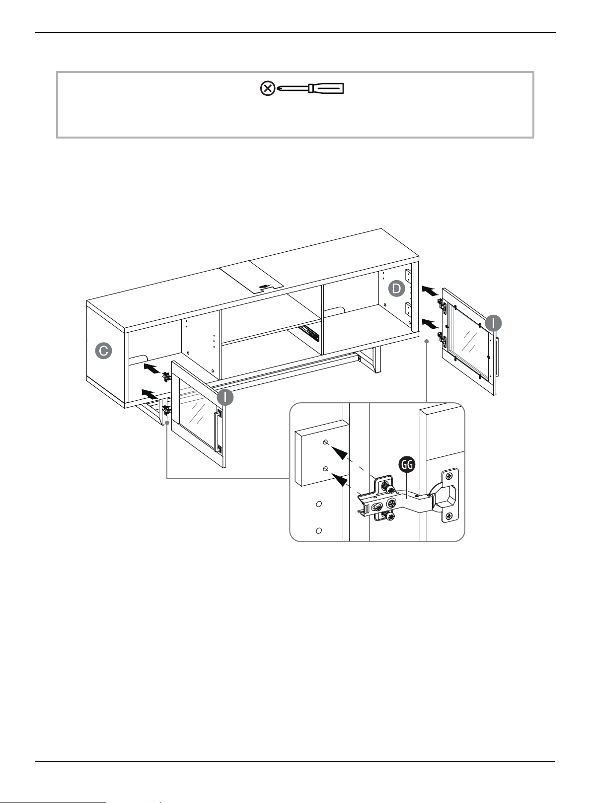
STEP 22: Install the doors
You n ee d :
1 Align one door (I) to the pre-attached bolts on the two hinges (GG) with the threaded holes on the hinge supports on
the left side panel (C), then secure with a Phillips screwdriver.
2 Repeat the same process to attach the other door (I) to the right side panel (D).
3 Open and close the doors to make sure they are aligned and shut correctly. If necessary, adjust the screws on the hinge
arm for a better fit.
Phillips screwdriver
www.insigniaproducts.com
30
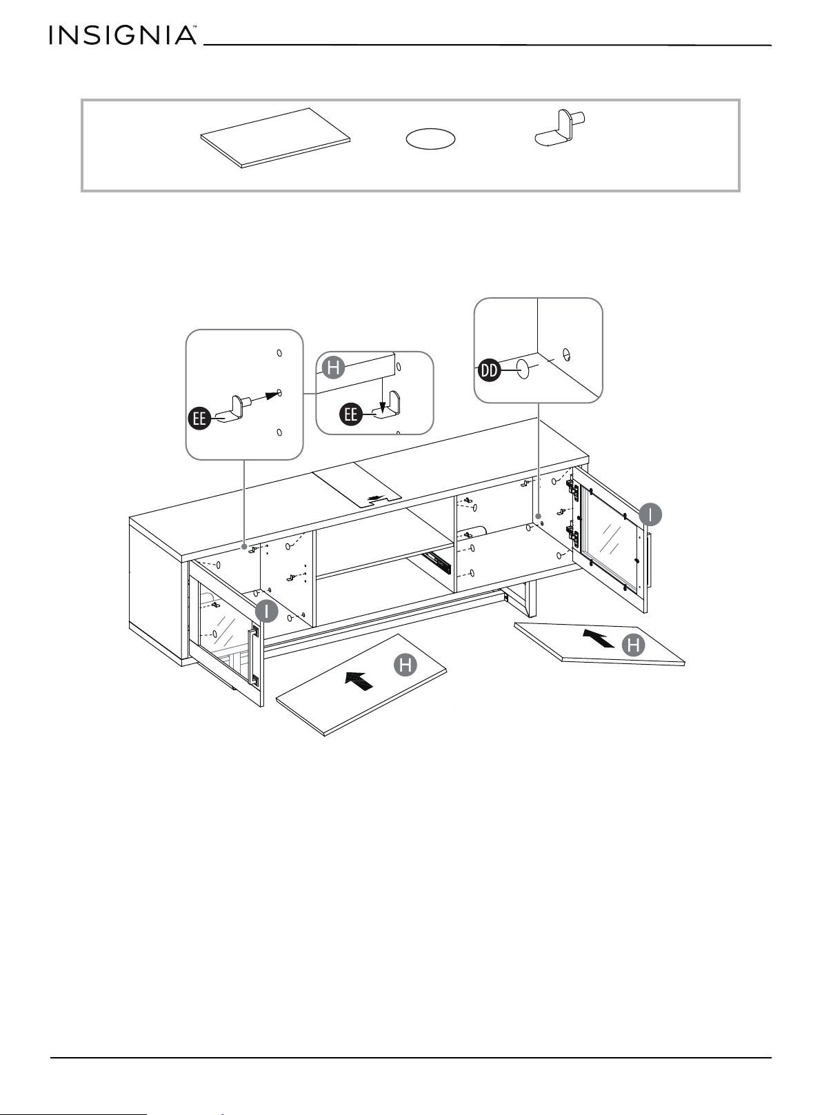
STEP 23: Install the adjustable shelves
You n ee d :
1 Place the PVC covers (DD) onto the visible cam locks to conceal them.
2 Open the doors (I) and insert four shelf supports (EE) into the holes at the desired height inside each side
compartment. Make sure that you place the four shelf supports at the same level so the shelves are not tilted. Tilt and
rest the adjustable shelves (H) onto the shelf supports.
H Adjustable shelves (2)
DD PVC covers (16)
EE Shelf supports (8)
www.insigniaproducts.com
31
Console for TVs up to 80”
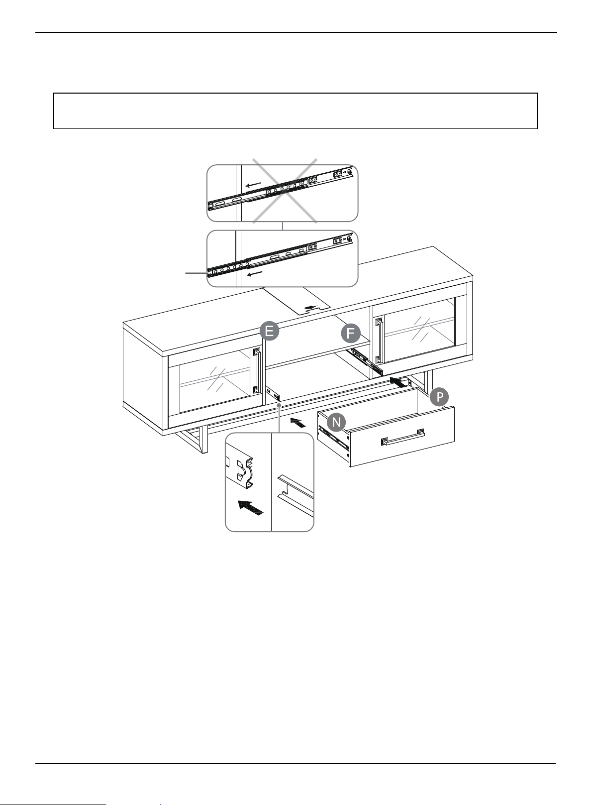
STEP 24: Insert the drawer
• Extend the ball bearing slide tracks on the partition panels (E and F) all the way forward (including ball bearing cart),
then align the slide runners on the assembled drawer with the slide tracks and push the drawer carefully inside until it
stops.
Tip: If the drawer does not go in smoothly, take it out and repeat the step. If you need to remove the drawer, pull the
drawer all the way out, then simultaneously push the plastic release lever on the ball bearing slides up on one side
and down on the other side, and then pull it completely out.
Ball bearing cart
Front
Front
www.insigniaproducts.com
32
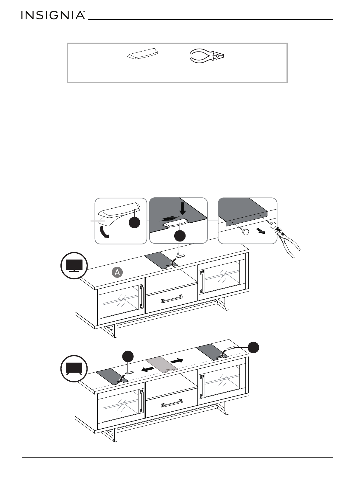
STEP 25: Attach the stopper to the top panel
You n ee d :
If you place your TV on top of your console, you must follow these instructions to prevent your TV from tipping. Otherwise,
skip to STEP 27: Position the TV console and install the tipping restraint
on page 34.
If your TV has one stand:
1 Remove the paper backing from the stopper (QQ), then place it in the stopper cut-out template on the top panel (A).
Press down on the stopper (QQ) to help it stick.
2 On the back of the top panel (A), carefully pull out the thumb tacks to remove the stopper template.
If your TV has two stands:
1 On the back of the top panel (A), carefully pull out the thumb tacks to remove the stopper template.
2 Align the template at the position where one of your TV’s stands or one of the feet will be located.
3 Remove the paper backing from the stopper (QQ), then place it in the stopper cut-out template on the top panel (A).
Press down on the stopper (QQ) to help it stick.
4 Repeat this process to attach the second stopper.
QQ Acrylic stopper (2) Pliers
QQ
QQ
QQ
QQ
Stopper backing
www.insigniaproducts.com
33
Console for TVs up to 80”
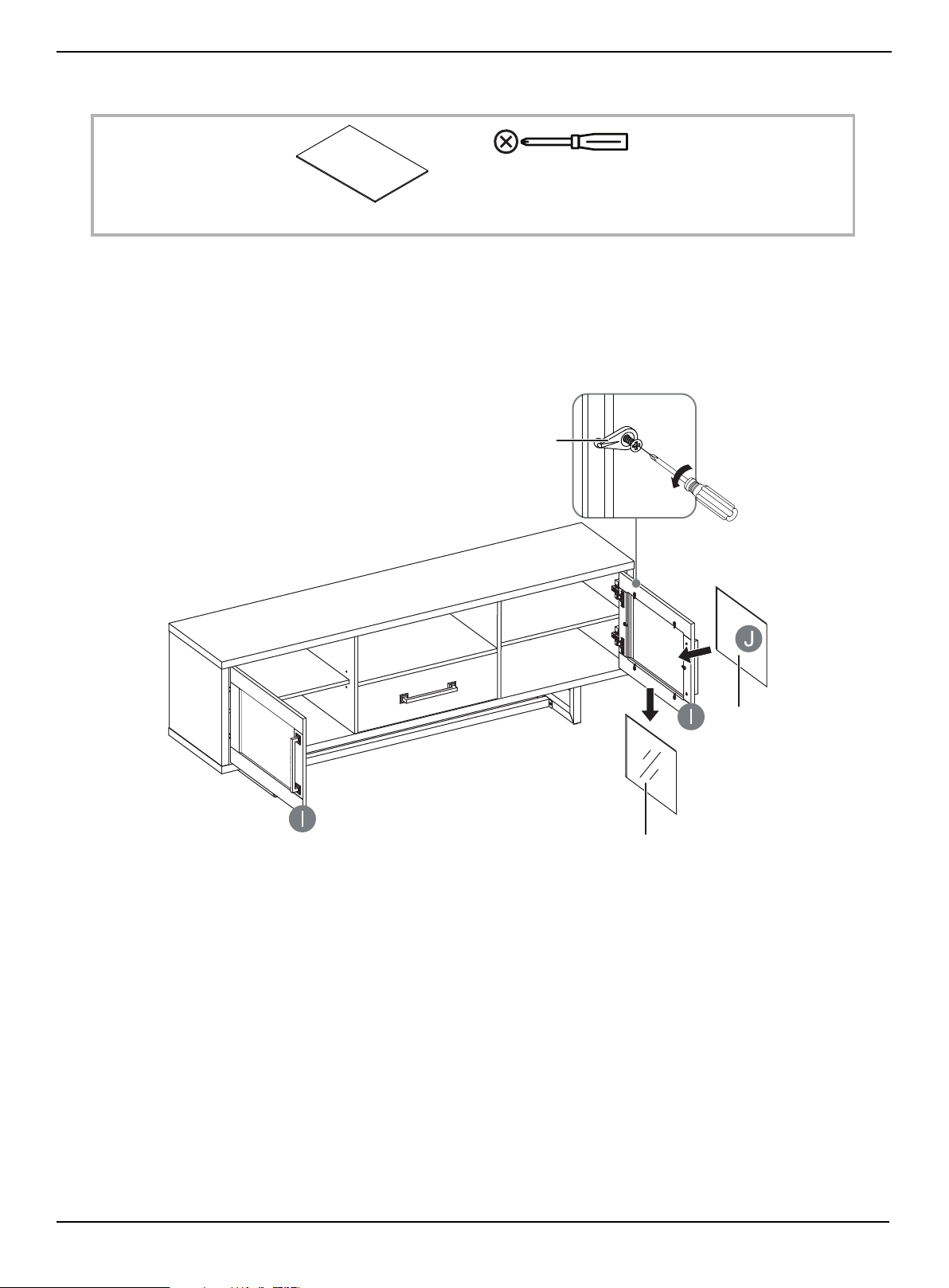
STEP 26: Change the door panel
You n ee d :
Follow these steps if you want to change your console’s door panels from glass to wood. Otherwise, skip this step.
1 Rotate the clips to remove the old panel. Loosen the screw on each of the clips if necessary
2 Insert the new panel, then rotate the clips and tighten the screws to secure the panel in the door frame.
3 Repeat this process to replace the other door panel.
Phillips screwdriver
J Wood panels (2)
Clip
Glass door panel
Wood door panel
www.insigniaproducts.com
34
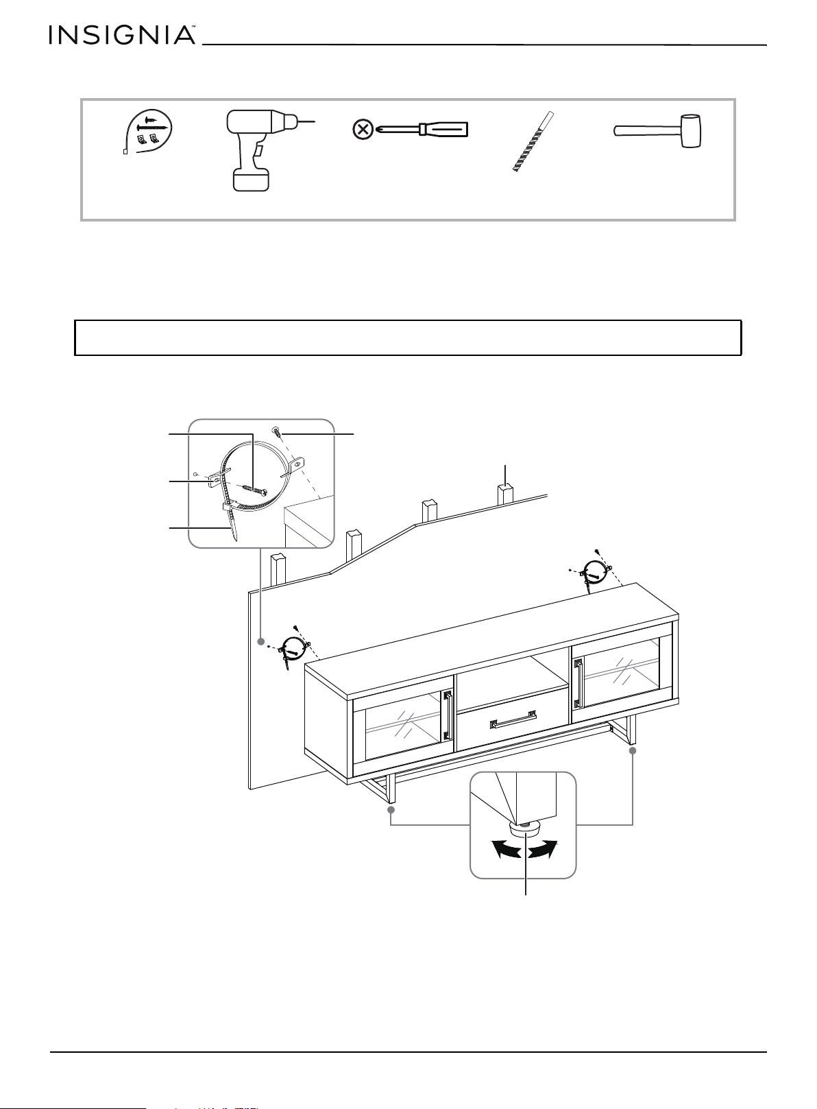
STEP 27: Position the TV console and install the tipping restraint
You n ee d :
1 Position the assembled console against the wall where you plan to use it.
2 Adjust the leveling feet to level the TV console.
3 Follow the instructions printed on the bag containing the tipping restraint hardware kit (UU) to attach the restraint
hardware to the wall and the console.
WARNING: It is very important that the tipping restraint be installed correctly. Failure to do this could result in your
TV console falling forward, resulting in damage to equipment or personal injury.
Drill
UU Tipping restraint (2)
Drill
Drill bit
Rubber mallet
Short screw
Metal bracket
Nylon strap
Wood stud
Leveling foot
Long screw
www.insigniaproducts.com
35
Console for TVs up to 80”
Maintaining your TV console
Wood/Laminate
• Use your favorite type of furniture polish.
• Do not spray polish directly onto the stand. Spray onto a soft cloth, then wipe the stand.
• Always test any polish in a discrete location first, such as the back of the stand, to make sure that there is no adverse
reaction.
• Dust frequently with a soft cloth.
• Never slide objects across surfaces. Lift objects from the top surface rather than dragging them across the finish when
moving them.
• Do not expose your stand to direct sunlight, drying heat sources, or dampness.
• Clean spills immediately with a soft, damp cloth.
• Use a protective pad when using your stand as a writing surface (especially when using a ballpoint pen).
Glass
• Use a commercial liquid glass cleaner and a soft cloth.
• Do not use harsh powders or any other abrasive substances because they can scratch the glass.
• Dust frequently with a soft cloth.
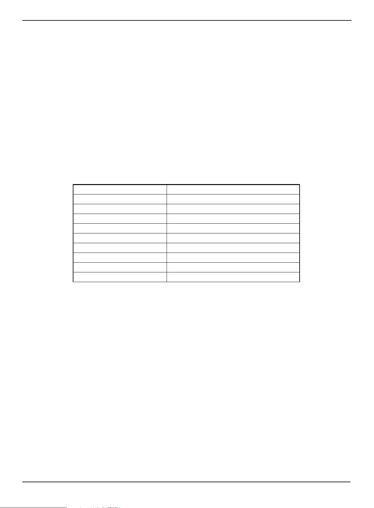
Specifications
Maximum overall weight 415 lbs. (187.8 kg)
Maximum top panel weight 135 lbs. (61.2 kg)
Maximum shelf weight 50 lbs. (22.6 kg)
Maximum drawer weight 30 lbs. (13.6 kg)
Maximum TV weight 135 lbs. (61.2 kg)
Maximum screen size 80”
Overall dimensions (H ×W× D) 24.3 × 70 × 16.6 in. (61.6 × 177.8 × 42.3 cm)
Drawer dimensions (H ×W× D) 6.5 × 21.7 × 12.5 in. (16.5 × 55.2 × 31.7 cm)
Shelf dimensions (W× D): 22 × 13.6 in. (55.8 x 34.5 cm)
TV stand weight: 106.7 lbs. (48.5 kg)

www.insigniaproducts.com
36
ONE-YEAR LIMITED WARRANTY
Definitions:
The Distributor* of Insignia branded products warrants to you, the original purchaser of this new Insignia-branded product (“Product”), that the
Product shall be free of defects in the original manufacturer of the material or workmanship for a period of one (1) year from the date of your purchase
of the Product (“Warranty Period”).
For this warranty to apply, your Product must be purchased in the United States or Canada from a Best Buy branded retail store or online at
www.bestbuy.com
or www.bestbuy.ca and is packaged with this warranty statement.
How long does the coverage last?
The Warranty Period lasts for 1 year (365 days) from the date you purchased the Product. Your purchase date is printed on the receipt you received
with the Product.
What does this warranty cover?
During the Warranty Period, if the original manufacture of the material or workmanship of the Product is determined to be defective by an authorized
Insignia repair center or store personnel, Insignia will (at its sole option): (1) repair the Product with new or rebuilt parts; or (2) replace the Product at
no charge with new or rebuilt comparable products or parts. Products and parts replaced under this warranty become the property of Insignia and are
not returned to you. If service of Products or parts are required after the Warranty Period expires, you must pay all labor and parts charges. This
warranty lasts as long as you own your Insignia Product during the Warranty Period. Warranty coverage terminates if you sell or otherwise transfer the
Product.
How to obtain warranty service?
If you purchased the Product at a Best Buy retail store location or from a Best Buy online website (www.bestbuy.com or www.bestbuy.ca), please take
your original receipt and the Product to any Best Buy store. Make sure that you place the Product in its original packaging or packaging that provides
the same amount of protection as the original packaging.
To obtain warranty service, in the United States call 1-888-BESTBUY or in Canada call 1-866-BESTBUY. Call agents may diagnose and correct the issue
over the phone.
Where is the warranty valid?
This warranty is valid only in the United States and Canada at Best Buy branded retail stores or websites to the original purchaser of the product in the
country where the original purchase was made.
What does the warranty not cover?
This warranty does not cover:
• Customer instruction/education
•Installation
•Set up adjustments
• Cosmetic damage
• Damage due to weather, lightning, and other acts of God, such as power surges
• Accidental damage
•Misuse
•Abuse
•Negligence
• Commercial purposes/use, including but not limited to use in a place of business or in communal areas of a multiple dwelling condominium or
apartment complex, or otherwise used in a place of other than a private home.
• Modification of any part of the Product, including the antenna
• Display panel damaged by static (non-moving) images applied for lengthy periods (burn-in).
• Damage due to incorrect operation or maintenance
• Connection to an incorrect voltage or power supply
• Attempted repair by any person not authorized by Insignia to service the Product
• Products sold “as is” or “with all faults”
• Consumables, including but not limited to batteries (i.e. AA, AAA, C, etc.)
• Products where the factory applied serial number has been altered or removed
• Loss or Theft of this product or any part of the product
• Display panels containing up to three (3) pixel failures (dots that are dark or incorrectly illuminated) grouped in an area smaller than one tenth
(1/10) of the display size or up to five (5) pixel failures throughout the display. (Pixel based displays may contain a limited number of pixels that
may not function normally.)
• Failures or Damage caused by any contact including but not limited to liquids, gels or pastes.
REPAIR REPLACEMENT AS PROVIDED UNDER THIS WARRANTY IS YOUR EXCLUSIVE REMEDY FOR BREACH OF WARRANTY. INSIGNIA SHALL NOT BE
LIABLE FOR ANY INCIDENTAL OR CONSEQUENTIAL DAMAGES FOR THE BREACH OF ANY EXPRESS OR IMPLIED WARRANTY ON THIS PRODUCT,
INCLUDING, BUT NOT LIMITED TO, LOST DATA, LOSS OF USE OF YOUR PRODUCT, LOST BUSINESS OR LOST PROFITS. INSIGNIA PRODUCTS MAKES NO
OTHER EXPRESS WARRANTIES WITH RESPECT TO THE PRODUCT, ALL EXPRESS AND IMPLIED WARRANTIES FOR THE PRODUCT, INCLUDING BUT NOT
LIMITED TO ANY IMPLIED WARRANTIES OF AND CONDITIONS OF MERCHANTABILITY AND FITNESS FOR A PARTICULAR PURPOSE, ARE LIMITED IN
DURATION TO THE WARRANTY PERIOD SET FORTH ABOVE AND NO WARRANTIES, WHETHER EXPRESS OR IMPLIED, WILL APPLY AFTER THE WARRANTY
PERIOD. SOME STATES, PROVINCES AND JURISDICTIONS DO NOT ALLOW LIMITATIONS ON HOW LONG AN IMPLIED WARRANTY LASTS, SO THE ABOVE
LIMITATION MAY NOT APPLY TO YOU. THIS WARRANTY GIVES YOU SPECIFIC LEGAL RIGHTS, AND YOU MAY ALSO HAVE OTHER RIGHTS, WHICH VARY
FROM STATE TO STATE OR PROVINCE TO PROVINCE.
Contact Insignia:
1-877-467-4289
www.insigniaproducts.com
INSIGNIA is a trademark of Best Buy and its affiliated companies.
*Distributed by Best Buy Purchasing, LLC
7601 Penn Ave South, Richfield, MN 55423 U.S.A.
©2021 Best Buy. All rights reserved.

www.insigniaproducts.com
1-877-467-4289 (U.S. and Canada) or 01-800-926-3000 (Mexico)
INSIGNIA is a trademark of Best Buy and its affiliated companies.
Distributed by Best Buy Purchasing, LLC
7601 Penn Ave South, Richfield, MN 55423 U.S.A.
©2021 Best Buy. All rights reserved.
V1 ENGLISH
21-0285