Loading ...
Loading ...
Loading ...
Version 20190806 Page
5
PRE - INSTALLATION
Decide where to install the receiver box before proceeding. The receiver is designed to be wall-mounted into a standard
wall switch box (STRONGLY SUGGESTED).
Otherwise, you can place it under or near the fireplace hearth (*IMPORTANT: Keep away from high-heat of exceeding
130°F. Additional protection is required for no exposure to the heat).
WALL MOUNTING
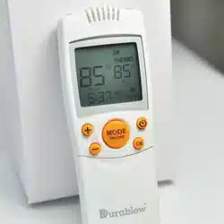
1. Install four AA-size 1.5V batteries into the remote receiver box(Fig 8). The system operates well with all batteries’
total output voltage is greater than 5.2V. Generally, four NEW AA-size batteries should output voltage of 6.0 to 6.2
volts if installed in series.
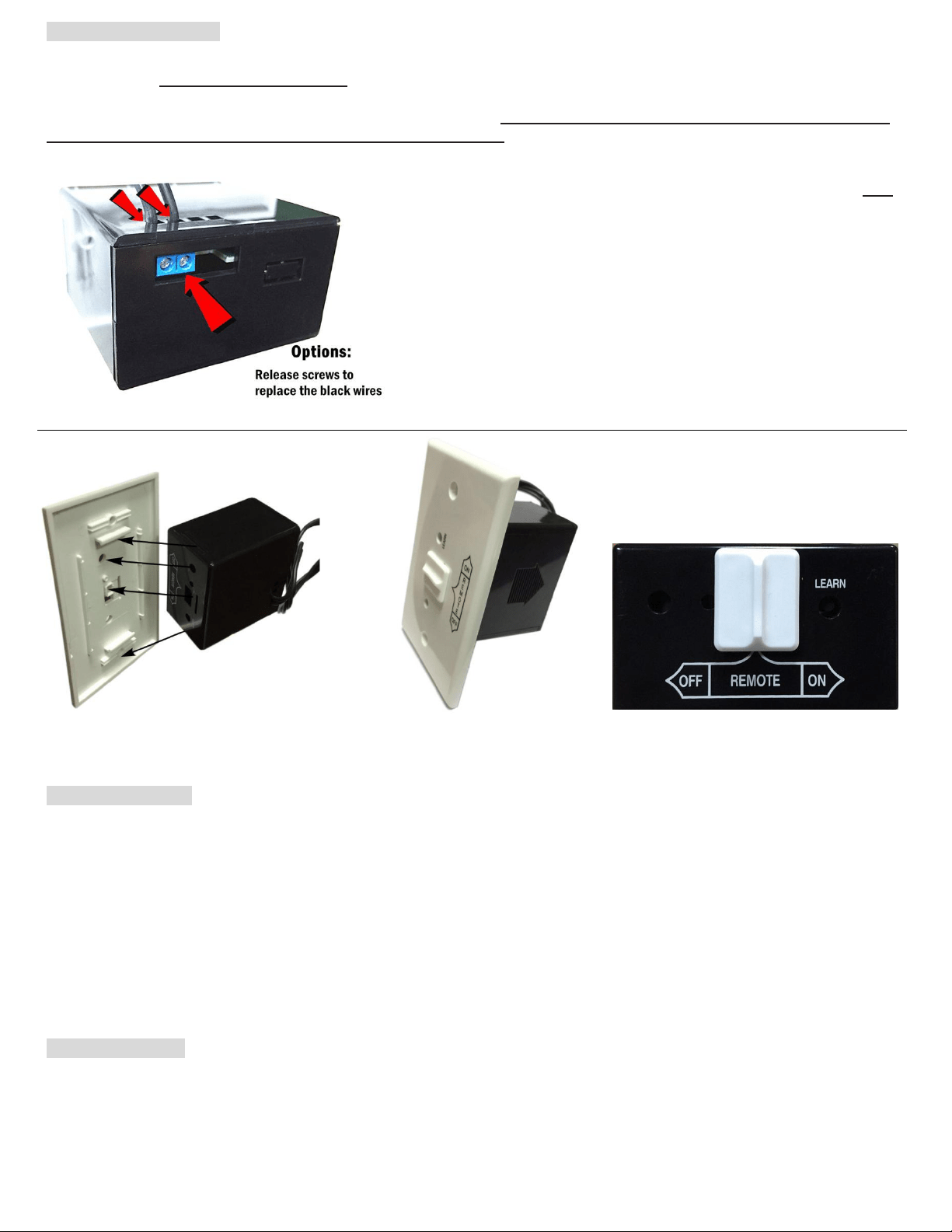
2. Attach wall mount cover plate to receiver box (Fig. 11). Press the receiver and have it snap into top & bottom tabs
of cover plate.
3. Position the cover plate to have words facing up (Fig. 12) Install the remote receiver box into the wall switch box
with two provided switch box long screws.
NOTE: The remote receiver box will only receive signal from the transmitter in the REMOTE position (middle). The remote
receiver box code must be matched to the transmitter prior to initial use (see LEARNING TRANSMITTER TO RECEIVER).
HEARTH MOUNT
The remote receiver box can be placed on the fireplace, under the fireplace, behind the control panel or louvers....etc. Keep
away from high-heat of exceeding 130°F. Additional protection is required for no exposure to the heat. The Slide switch
button should be installed on the receiver box for Hearth Mount (Fig. 13).
Make sure the receiver box’s slide switch is in the OFF
position before installation.
The receiver is connected with 18-inches of black wire. If
additional length of wire is required, for the best results, 18
gauge stranded or solid wire are recommended. Splice with
the original black wires of the receiver box. Or, remove the
black wires and insert new wires directly into the slots at
back of receiver box (Fig, 10). Wires are NOT longer than 20-
feet. Please allow some wire / space to remove the receiver
for battery replacement or check.
Fig. 10
Fig. 11
Fig. 12
Fig. 13
Loading ...
Loading ...
Loading ...