Loading ...
Loading ...
Loading ...
Version 20190806 Page
4
REMOTE RECEIVER BOX
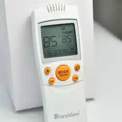
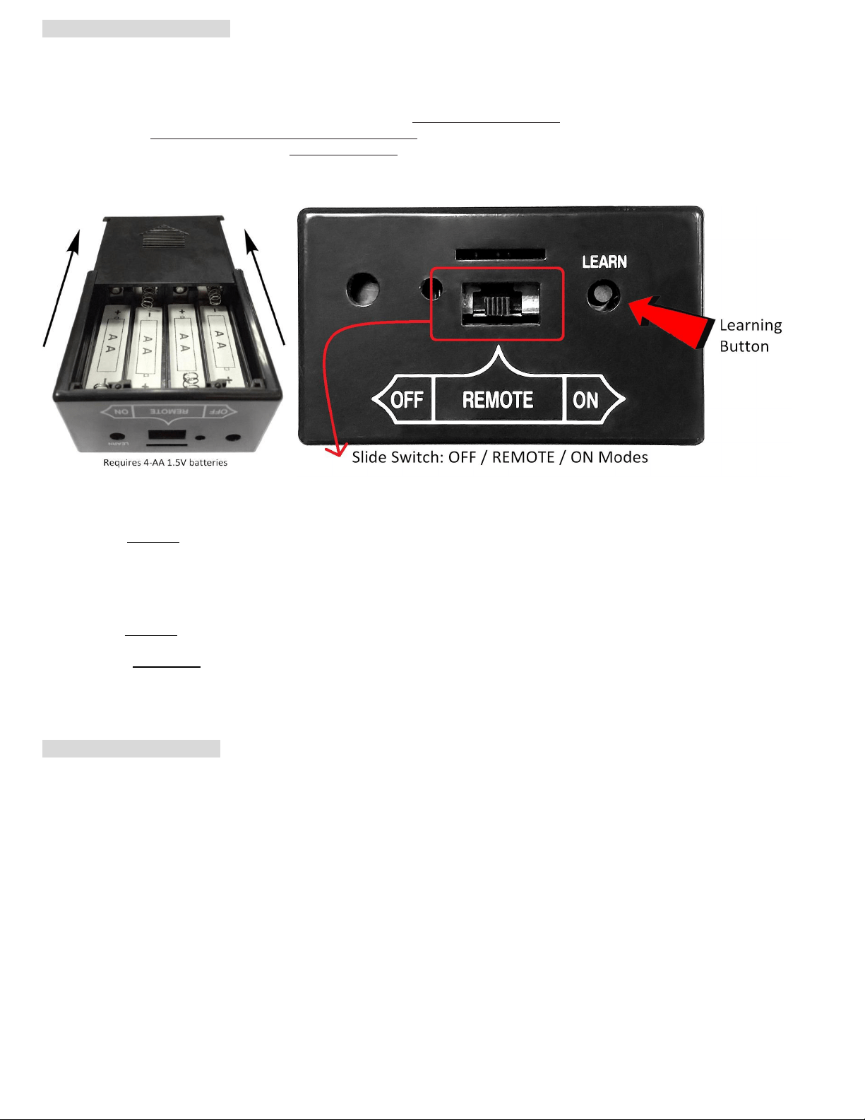
The remote receiver box requires four AA-size 1.5V batteries (excluded) (Fig. 8). When LOW battery icon appears on the
screen, please replace batteries.
The remote receiver box equips the microprocessor that receives the signals / commands from the transmitter in order to
control system operations / functions. It makes sounds of quick BEEP X 2 (♫, ♫) when it receives an “ON” command, and
makes sound of continuous BEEP for one second ( ♫ ~~~) when it receives an “OFF” command manually (or when Timer
ends automatically). But no beep when cycling ON / OFF automatically in THERMO
*2
mode.
The remote receiver box has a 3-position slide switch (OFF/REMOTE/ON) and a LEARN button on the front panel (Fig. 8).
Fig. 8
Fig. 9
ON mode: Slide the switch to the ON position (toward the LEARN button), the system will remain ON all the time. Remote
transmitter is disabled.
REMOTE mode: Slide the switch to the REMOTE position (middle), the system will ONLY operate with receiving commands
from the remote transmitter.
OFF mode: Slide the switch to the OFF position, the system will remain OFF all the time. Remote transmitter and Receiver
box are both disabled.
★NOTE: The OFF mode is strongly recommended if house is unattended for a long time. For safety, placing the slide switch
in the OFF position also functions as a safety “LOCK-OUT” by both turning the system off and disable the remote receiver.
W
ARNING & REMINDER
This system MUST be installed exactly as complied with these instructions. Read all instructions before installation,
and follow them during installation carefully.
Any modifications of Durablow remote control system, or parts, or components are PROHIBITED. They will void the
warranty, and may cause a fire hazard result in human casualties and property damages.
Do NOT connect any gas valve or electronic module directly to 110-120VAC power.
Read gas appliance manufacturer’s instructions and wiring schematics completely for proper placement of all
wires. All electronic modules are to be wired to manufacturer’s specifications.
All wiring diagrams in these instructions are for illustration purpose ONLY. Follow instructions from manufacturers of
gas valve and electronic module for correct wiring & installation procedures. Improper installation of electric components
can cause damage to electronic module, gas valve and remote receiver.
Loading ...
Loading ...
Loading ...