Loading ...
Loading ...
Loading ...
8. WIRING DIAGRAM
36K
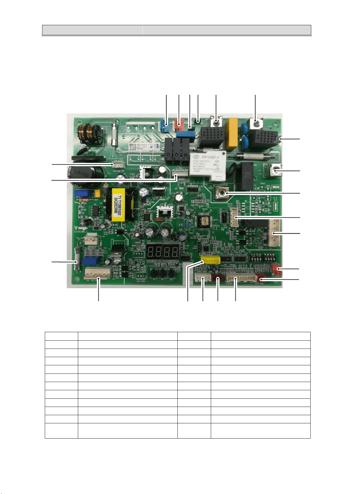
Main control board
NO. Description NO. Description
1 Tube electric heater 12 Pressure switch
2 4-way valve 13 Compressor heating protector
3 Electric heating belt L 14 Sensor Signal Out Suc. Coil Def. Diss.
4 Electric heating belt N 15 Pressure sensor
5 N Out to driver board Nin 16 Computer socket
6 AC Power Nin 17 EE data socket
7 Earth 18 DC motor
8 AC Power Lin 19 DC310V from electrolytic capacitor
9 L Out to driver board Lin 20 Communication signal to driver board
10 Electronic expansion valve 21 Power to driver board
11
Communication signal to thermostat and
indoor
1
1718
2
16
3
15
4 5 6
14
7
8
9
21
10
20
11
19
12
13
28
Loading ...
Loading ...
Loading ...