Loading ...
Loading ...
Loading ...
Large Unit Heater
6
Operating Instructions and Owner’s Manual
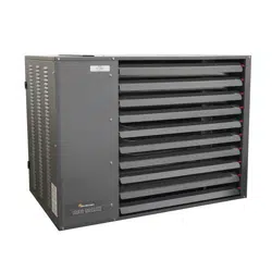
Heater Subcomponents
FIGURE 3
Flame Sensor
Pressure
Switch
Control
Board
Spark Electrode
Gas Valve
Manual Reset
Safety Gas
Switchers
Control Transformer
Draft Inducer
High Limit Switch
INITIAL INSTALLATION CONSIDERATIONS AND
PRE-CHECKS
WARNING: Improper installation, adjustment, alteration,
service, or maintenance can cause property damage, serious
injury, or death. Read and understand the installation,
operating, and maintenance instructions thoroughly before
installing or servicing this equipment.
This manual should be kept for future use for servicing or
service diagnostics. Leave manual with the owner. Do not
discard any literature shipped with this unit. Only a trained,
qualified installation or service personnel may install or
service this equipment.
Do not attach ductwork, air filters, or polytubes to any
propeller unit heater.
Placement of the heater is influenced by many factors. Aside from
safety factors, considerations for the general space and heating
requirements, availability of gas and electrical supply, and proximity of
possible vent locations are a few examples of factors that should all be
considered.
Inspect and evaluate the location of the heater to ensure that the
structural support is adequate to support the unit’s weight. The unit
must be installed in a horizontally level position to ensure proper
operation. To reduce noise attenuation along the structure caused by
vibration of the unit, the heater should be installed within 15 feet of
a primary building support. In the cases where this installation is not
practical or feasible, the use of spring vibration isolators may be used,
so long as they are rated for use of the unit’s weight.
Adequate space around the heater must also be considered in order
to maintain the published minimum clearance to combustibles and
recommended service clearances (see Table 3).
WARNING: Do not locate any gas-fired units in area where
chlorinated, halogenated, or acid vapors are present in the
atmosphere. These substances can cause premature heat
exchanger failure due to corrosion which can cause property
damage, serious injury, or death.
In the U.S., the installation of these units must comply with the
National Fuel Gas Code, ANSI Z223.1 (NFPA 54) - latest edition and
other applicable local building codes. In Canada, the installation of
these units must comply with local plumbing or waste water codes
and other applicable codes and with the current code CSA-B149.1.
All installation and service of these units must be performed by a
qualified installation and service agency only as defined in ANSI Z223.1
(NFPA 54) - latest edition or in Canada by a licensed gas fitter.
This unit is certified with the controls furnished. For replacements
parts, please order according to the replacement parts list on rating
plate. Always know your model and serial numbers, we reserves the
right to substitute other authorized controls as replacements.
Unit is balanced for correct performance. Do not alter fan or operate
motors at speeds below what is shown in this manual.
Information on controls is supplied separately. The same burner is used
for natural and propane gas.
INSTALLATION
NOTICE: High humidity or saltwater atmospheres will accelerate heater
corrosion and reduce useful life. Do not install the heater in locations
where water (in the form of rain, drips, or spray) could fall onto the
gas ignition components.
WARNING: Improper suspension of the unit heater may
result in collapse and being crushed.
Always suspend from a permanent part of the building
structure that can evenly support the total force and weight
of the heater.
Failure to maintain minimum clearance to combustibles may
result in fire and/ or explosion, property damage, serious
injury, or death. Always maintain minimum clearances.
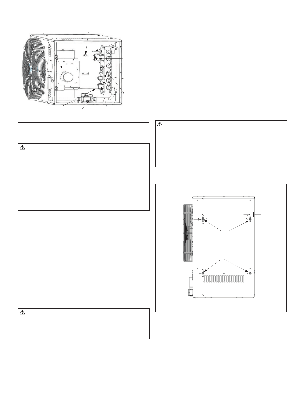
The units are designed to be hung with threaded bolts via the four (4)
threaded inserts on the top panel of the heater:
Hanging Points
FIGURE 4
HANGING
POINTS:
For the anchorage
of the unit heater
use 3/8”-16 bolts
or eyebolts
18.86 inch
(479mm)
1.63 inch
(41.5mm)
7.89 inch
(200.5mm)
9.16 inch
(233mm)
9.73 inch
(247mm)
22.13 inch
(562mm)
The suspension of the heater must conform to all applicable codes
referenced in the STANDARDS section.
To ensure proper operation, the heater must be installed in a level
horizontal position depending on desired location as governed by
clearances, vent connection, air direction, gas supply, electrical supply
and service accessibility.
Be sure the means of suspension is adequate to support the
weight of the unit (see Table 1 for unit weights).
Loading ...
Loading ...
Loading ...