Loading ...
Loading ...
Loading ...
Large Unit Heater
11
Operating Instructions and Owner’s Manual
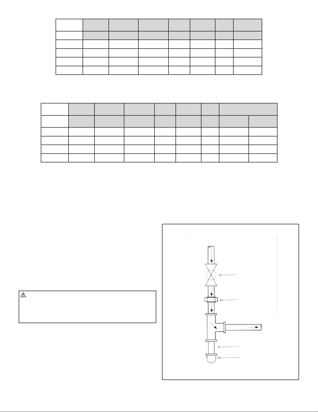
• A sediment trap meeting the typical requirements of Figure 9 shall
be installed in the line to the gas valve.
• A dedicated shutoff valve for the heater must be installed in the
gas supply line.
Refer to Table 5 for natural gas and Table 6 for propane to determine
the cubic feet per hour (CFH) required for the type of gas and size of
unit to be installed. To determine the proper pipe diameter, use the
CFH value and the length of pipe necessary. In the case where several
units are serviced by the same main gas line, the total capacity (CFH)
and length of main must be adequate to service all appliances down-
stream of this main.
• All piping must be installed in accordance with the requirements
outlined in the National Fuel Gas Code ANSI/Z223.1 (latest
edition) or CSA-B149.1 and B149.2. Support all gas supply piping
with pipe hangers, metal strapping, or other suitable material. Do
not rely on the heater to support the gas pipe.
WARNING: Always use two (2) opposing wrenches to tighten
mating pipe connections to prevent excessive torque on the
gas valve and manifold pipe. Excessive torque can damage
the valve and/or misalign the orifice, resulting in fire,
explosion, serious injury, or death.
• When connecting gas supply lines, the length of the piping run
from the gas meter to the heater must be considered in determin-
ing the pipe size to avoid excessive pressure drop.
• A drip leg should be installed in the vertical pipe run to the unit.
In some localities, codes may require that a manual main shutoff
valve and union (furnished by installer) be installed external to the
unit. Union must be of the ground joint type. A drip leg should be
readily accessible to permit cleaning and emptying. See Figure 9.
NOTICE: Leave a min of 4’’ clearance to the electrical connections box
on the back of the heater to allow for access.
A 1/8” NPT plugged tap shall be installed immediately upstream of the
gas supply connection to the heater. The purpose of this is to be able
to check for proper gas pressure entering the heater.
Gas Supply Connection
FIGURE 9
Sediment Trap
Drip Leg
Grounded Joint Union
Manual
Main Shut-off Valve
(Furnished by Installer)
Gas Flow
TABLE 5: Natural Gas Consumption
TABLE 6: Propane Gas Consumption
Gas supply
Connection
Gas supply
Pressure min.
Gas supply
Pressure max.
Manifold
Pressure
Orifice Drill
Size
# of
Orifices
Consump-
tion
[“] [“ W.C.] [“ W.C.] [“ W.C.] [“] [CFH]
MHU200NG
1/2 7 20 4.5 0.110 6 190.5
MHU250NG
1/2 7 20 4.9 0.110 7 238.1
MHU300NG
1/2 7 20 1.73 0.138 9 285.7
MHU400NG
3/4 7 20 2.13 0.138 11 380.9
Gas supply
Connection
Gas supply
Pressure min.
Gas supply
Pressure max.
Manifold
Pressure
Orifice Drill
Size
# of
Orifices
Consumption
[“] [“ W.C.] [“ W.C.] [“ W.C.] [“] [CFH] [Gal/Hr.
Propane]
MHU200NG
1/2 11 20 7.23 0.075 6 80.0 2.19
MHU250NG
1/2 11 20 7.23 0.075 7 100.0 2.74
MHU300NG
1/2 11 20 3.81 0.084 9 120.0 3.29
MHU400NG
3/4 11 20 4.74 0.084 11 160.0 4.38
*Assumes an average heating value of 1050 BTU/SCF and a Specific Gravity of 0.60.
*Assumes an average heating value of 2500 BTU/SCF and a Specific Gravity of 1.53.
Loading ...
Loading ...
Loading ...