Loading ...
Loading ...
Loading ...
Large Unit Heater
17
Operating Instructions and Owner’s Manual
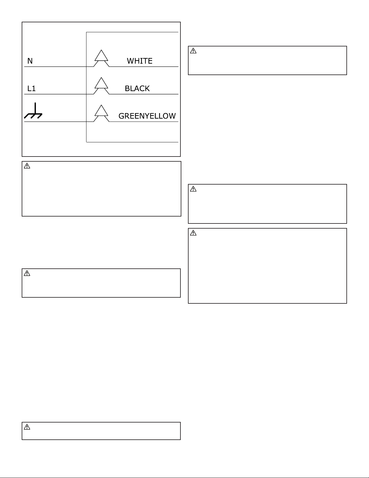
Line Voltage Field Wiring
FIGURE 12
WARNING: Electric shock hazard. Can cause injury or death.
Do not use this heater if any part has been under water.
Immediately call a qualified service technician to inspect the
furnace and to replace any part of the control system and
any gas control which has been under water.
Before attempting to perform any service or maintenance,
turn the electrical power to unit OFF at disconnect
switch(es). Unit may have multiple power supplies.
FIELD WIRING SUPPLY VOLTAGE
Before proceeding with electrical connections, ensure that the supply
voltage, frequency, phase, and current capacity meet the requirements
specified on the rating plate. A dedicated line voltage supply with
properly sized wire should run directly from the main electrical panel to
the heater.
CAUTION: The power supply to the heater must be within
+/- 5% of the voltage rating as indicated on the rating
plate of the appliance. If input power does not meet these
specifications, contact your utility company.
• An electrical service disconnect must be provided at the furnace
location. A 2 x 4 junction box can be mounted directly to the unit
panel utilizing the provided 1/2” knock-out. If conditions do not
allow for this, locate the service disconnect not more than 5 feet
away from the service access panel.
• The main electrical supply enters at the rear of the heater utilizing
1/2” electrical knock-out. When routing the electrical supply
conduit to the unit, ensure that it does not interfere or obstruct
the heater’s service access panel.
• Unit comes with three wire leads to connect the main power
supply. Connect the hot, neutral, and ground wires as shown
in the field wiring diagram. When routing wires through the
knockout, use a UL Listed bushing or chase nipple to prevent
damage to the wire insulation. When operating this unit as a
sealed combustion appliance, the cabinet opening to the junction
box must be sealed air tight using either a UL approved bushing
or a non-reactive UL approved sealant to bushing.
WARNING: Edges of sheet metal holes may be sharp. Use
gloves as a precaution when routing wires.
• Connect wires together with UL approved wire connectors.
NOTICE: A UL Listed switch may be installed in the 2x4 junction box
for use as a service disconnect.
CAUTION: Route the field supplied power wires so that
they do not come in contact with the flue wrapper or
venter housing. These hot surfaces may damage the wire’s
insulation, resulting in damage to the unit.
THERMOSTAT LOCATION
The location of the thermostat should be determined by the desired
heating requirements and be mounted on an inside wall five (5) feet
above the finished floor. Locate the thermostat in a conspicuous
location, away from where it could be influenced by heat from the unit
or other sources, as this may cause the unit to short cycle. Care should
be given to locate the thermostat away from drafts or frequently
opened doors. To prevent drafts inside the wall from affecting the
thermostat’s performance, plug hole for the wire with insulation
or suitable caulk. For further information, see the accompanying
instructions with the thermostat.
START-UP OPERATION
UNIT START–UP
WARNING: Improper installation, adjustment, alteration,
service, or maintenance can cause property damage, serious
injury, or death. This heater must be installed and serviced
by a trained gas installation and service personnel only.
During heater startup ensure that building is well ventilated.
CAUTION: Shock Hazard. Before attempting to perform any
service or maintenance, turn electrical power to unit OFF at
disconnect switch.
During the first unit startup, an odor and, perhaps,
some vapor will come from the heater. This is the gasket
binding material emitting this odor and/ or vapor. After
approximately 20 minutes, this odor will disappear and not
occur again.
During these 20 minutes it is recommended to ventilate the
room as much as possible (open doors, windows, turn on
any fans).
Pre-Start Up Checks
Verify that the installation conforms to all of the specifications of the
manual, as well as with local, state, national, and provincial codes. In
absence of local codes, the unit heater must be installed according to
the current National Fuel Gas Code ANSI Z223.1 (NFPA 54). In Canada,
the installation must conform to the current National Standard of
Canada CSA-B149 Sections 1 & 2.
Prior to starting up the unit, verify that:
• The gas type listed on the rating label matches that of your
application.
• The gas connections have been purged of air and properly leak
tested.
• The voltage type and frequency listed on the rating label matches
that of your application.
• The unit is properly grounded as per the National Electrical Code,
ANSI/NFPA 70 or Canadian Electrical code CSA C22.1 Part 1.
• The unit is properly mounted to a permanent structure able to
bear the weight of the unit.
Loading ...
Loading ...
Loading ...