Loading ...
Loading ...
Loading ...
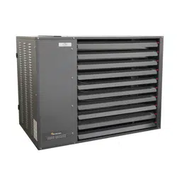
Large Unit Heater
23
Operating Instructions and Owner’s Manual
The electrode and sensor are not adjustable. DO
NOT change location or position as part of this
conversion kit.
Step 1
CAUTION: THE UNIT MUST NOT BE CONNECTED TO EITHER
THE GAS SUPPLY OR THE ELECTRICAL POWER SUPPLY,
BEFORE PROCEEDING WITH CONVERSION.
Step 2
Remove and retain the four screws holding the manifold on to the
burner box (Figure 14). Rotate the valve/ manifold assembly, away from
the burners (Figure 15). The valve/manifold assembly holds the orifices.
This will allow access to the orifices on the manifold.
Step 3
Remove and discard the adjustment spring cap from gas valve/
regulator with a flat blade screw driver by turning the screw counter-
clockwise.
Step 4
Remove and discard the orifices from the manifold with using a ½ “
open end wrench. Turn them counter-clockwise to remove. Take the
new orifices from the conversion kit and before installing, confirm that
the number stamped on the side of the orifice matches as indicated
in Table 1. If it does not, immediately contact Mr. Heater, Inc. for the
correct kit. If they are the correct orifices, install them in the manifold
using caution not to cross thread.
WARNING
THIS CONVERSION KIT SHALL BE INSTALLED BY A
QUALIFIED SERVICE AGENCY IN ACCORDANCE WITH THE
MANUFACTURER’S INSTRUCTIONS AND ALL APPLICABLE
CODES AND REQUIREMENTS OF THE AUTHORITY
HAVING JURISDICTION. IF THE INFORMATION IN THESE
INSTRUCTIONS IS NOT FOLLOWED EXACTLY, A FIRE,
EXPLOSION OR PRODUCTION OF CARBON MONOXIDE
MAY RESULT CAUSING PROPERTY DAMAGE, PERSONAL
INJURY OR LOSS OF LIFE. THE QUALIFIED SERVICE AGENCY
PERFORMING THIS WORK ASSUMES RESPONSIBILITY FOR
THE PROPER CONVERSION OF THIS APPLIANCE WITH THIS
KIT.
WARNING: Electrical Shock Hazard
UNPLUG THE ELECTRICAL CORD FROM THE OUT-
LET BEFORE PERFORMING ANY SERVICE MAINTE-
NANCE.
FAILURE TO FOLLOW THESE INSTRUCTIONS WILL
RESULT IN DEATH, INJURY OR PROPERTY DAM-
AGE.
WARNING: Explosion Hazard
TURN OFF THE GAS SUPPLY TO THE HEATER
BEFORE PERFORMING ANY SERVICE OR MAINTE-
NANCE.
FAILURE TO FOLLOW THESE INSTRUCTIONS WILL
RESULT IN DEATH, INJURY OR PROPERTY DAM-
AGE.
Step 5
Rotate the valve/ manifold assembly back up into the burner box,
making sure that all the orifices are indexed into the burners and are
not caught on the locating ring on the back of each burner. Secure the
manifold to the burner box with the four screws removed in step 2.
Step 6
Following the instructions Electrical Requirements and Gas Connections
Sections (making sure to leak check all connections with soapy water)
to reinstall the heater.
Step 7
Take the rate tag from the kit and stick it over the existing portion of
the rate label. This tag is preprinted with all the correct information for
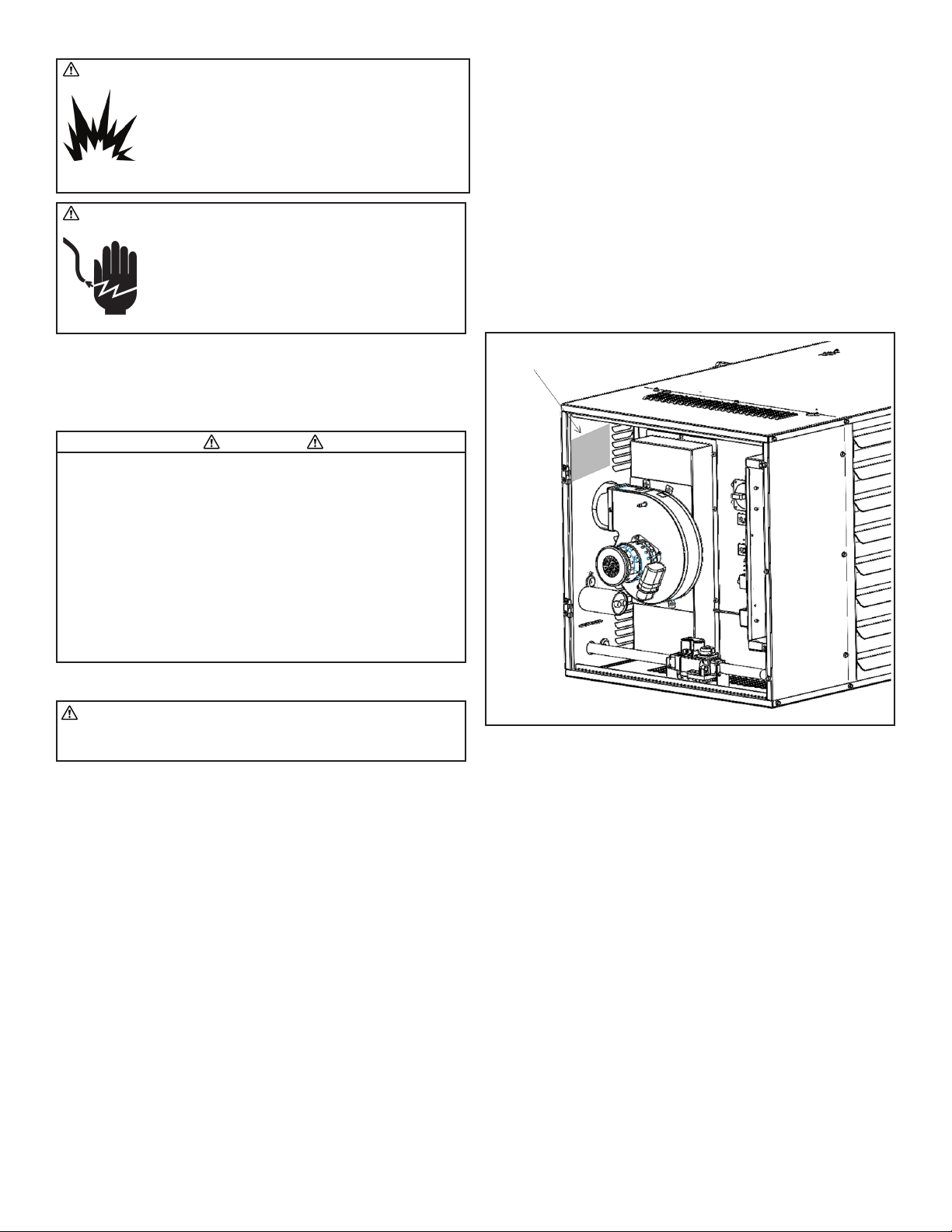
the converted heater. See Figure 16.
FIGURE 16
Position Of The Rate Tag
Step 8
Remove the converted information tag from the kit and fill in the
information. Then place this tag below the updated rating tag on the
unit.
Step 9
Replace any panels and operate heater following all warnings/cautions
and instructions in the operator’s manual and labels.
Loading ...
Loading ...
Loading ...