
Loading ...
Loading ...
Loading ...
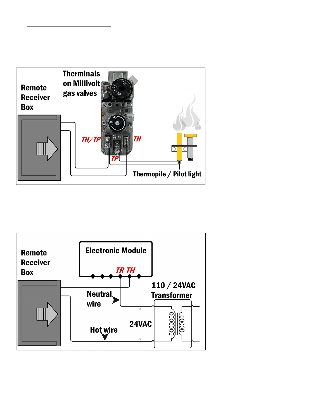
a. WIRING MILLIVOLT VALVE (Fig. 9)
Connect the two 18 gauge stranded or solid wires of the Remote receiver box to the Millivolt gas valve at the TH & TH/TP
terminals on the terminal block. It does not matter which wire go to which terminal.
The remote receiver box‘s operation is similar to a thermostat that also turn the gas valve ON and OFF based on the
input signals from TH & TH/TP terminals. Transmitter sends signals to receiver box, and receiver box pass the signals to
Millivolt valve to function the ON and OFF of fire / heater.
Fig. 9
b. WIRING ELECTRONIC SPARK IGNITION MODULE (Fig. 10)
Connect a 24VAC transformer in series to the TR (transformer) terminal on the ELECTRONIC MODULE. Connect the
hot wire from the 24VAC transformer to either of the wire terminals on the remote receiver box. Connect another wire
between receiver wire terminal and the TH (thermostat) terminal on the ELECTRONIC MODULE.
Fig. 10
c. REPLACING ON/OFF WALL SWITCH
See Fig. 6 and 7. Replace the existing manual ON/OFF wall switch with our receiver box and wall mount cover plate.
Page 5
Loading ...
Loading ...
Loading ...