W415-0809 / D / 02.26.21
ADD MANUAL TITLE
Wolf Steel Ltd., 24 Napoleon Rd., Barrie, ON, L4M 0G8 Canada / 103 Miller Drive, Crittenden, Kentucky, USA, 41030
Phone 1 (866) 820-8686 • www.napoleon.com • [email protected]
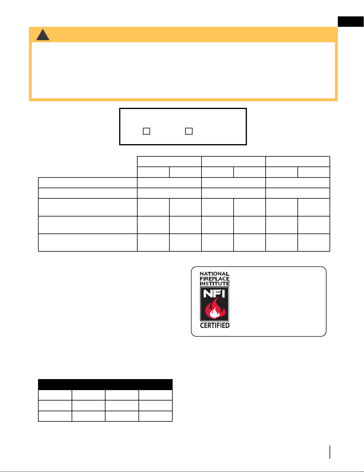
CERTIFIED TO THE AMERICAN NATIONAL STANDARD:
ANSI _______ FOR _____________________________________________________
INSTALLER:
Leave this manual with the appliance
CONSUMER:
Retain this manual for future reference
ADD PRODUCT CODE HERE (TRADE GOTHIC LT STD FONT)
NATURAL GAS MODELS:
PROPANE GAS MODELS:
Product Name / Code
(MUST use title from Price Book)
ADD ____ ILLUSTRATED
ADD PRODUCT IMAGE
CERTIFICATION
LOGO
SAFETY INFORMATION
- Do not store or use gasoline or other
fl ammable vapors and liquids in the vicinity of
this or any other appliance.
- WHAT TO DO IF YOU SMELL GAS:
• Do not try to light any appliance.
• Do not touch any electrical switch; do not
use any phone in your building.
• Immediately call your gas supplier from a
neighbour’s phone. Follow the gas
supplier’s instructions.
• If you cannot reach your gas supplier, call
the fi re department.
- Installation and service must be
performed by a qualifi ed installer, service
agency, or the supplier.
- This is an unvented gas-fi red heater that
uses air (oxygen) from the room in which
it is installed. Provisions for adequate
combustion and ventilation air must be
provided. Refer to section “combustion
and ventilation air provisions”.
FIRE OR EXPLOSION HAZARD
Failure to follow safety warnings exactly
could result in serious injury, death, or
property damage.
WARNING
!
ENGLISH
$10.00
FOR INDOOR USE ONLY
IF INSTALLATION + OPERATION, ADD SERIAL
NUMBER LABEL HERE
IF SEPARATE MANUALS, ADD “PLACE
BARCODE LABEL ON THE OWNER’S MANUAL”
Insert appropriate statement (see margins).
This appliance may be installed in an aftermar-
ket, permanently located, manufactured-home
(USA only) or mobile home, where not
prohibited by local codes.
This appliance is only for use with the type of
gas indicated on the rating plate. This appliance
is not convertible for use with other gases.
CERTIFIED TO: ANSI Z21.11.2 UNVENTED HEATERS
ANSI Z21.60 / CSA 2.26 DECORATIVE GAS APPLIANCES FOR INSTALLATION IN SOLID-FUEL
BURNING APPLIANCES
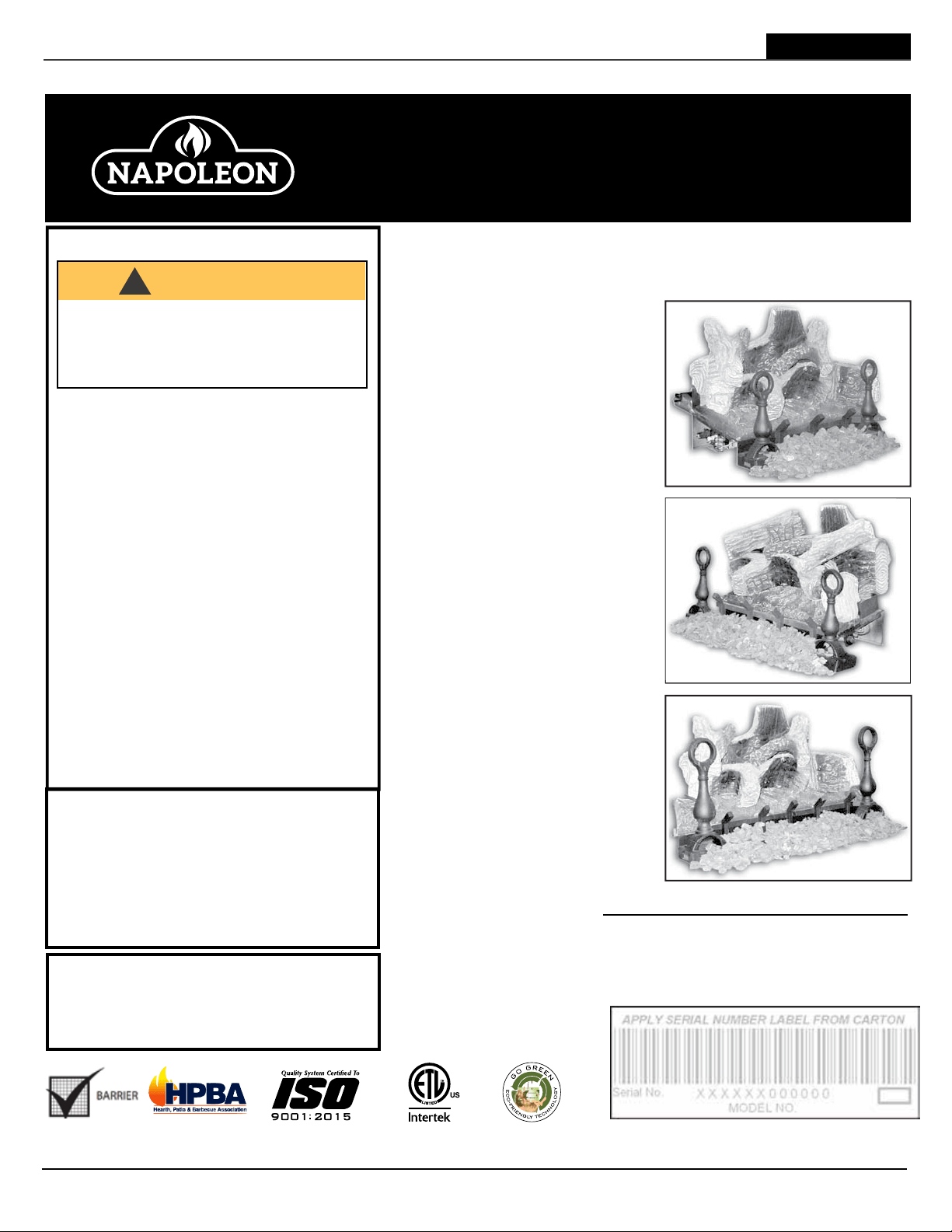
These log sets can be installed in vented or unvented applications.
GVFL18P / GVFL24P / GVFL30P
INSTALLATION AND
OPERATION MANUAL
GVFL18N / GVFL24N / GVFL30N
Fiberglow™ Series
GVFL18
GVFL24
GVFL30
W415-0809 / D / 02.26.21
EN
2
safety information
• This appliance is hot when operated and
can cause severe burns if contacted.
• Any changes or alterations to this
appliance or its controls can be
dangerous and is prohibited.
• Do not operate appliance before reading and
understanding operating instructions. Failure
to operate appliance according to operating
instructions could cause fi re or injury.
• Ensure the glass door is opened or removed
when lighting the pilot for the fi rst time and
when the gas supply has run out.
• Risk of fi re or asphyxiation, do not operate
appliance with fi xed glass removed and never
obstruct the front opening of the appliance.
• Do not connect 110 volts to the control valve,
with the exception of models; GSST8 and
GT8.
• Risk of burns. The appliance should be turned off and cooled before servicing.
• Do not install damaged, incomplete or substitute components.
• Risk of cuts and abrasions. Wear protective gloves, protective footwear, and safety glasses during
installation. Sheet metal edges may be sharp.
• Do not burn wood or other materials in this appliance.
• Provide adequate ventilation and combustion air. Provide adequate accessibility clearance for servicing
and operating the appliance.
• High pressure will damage valve. Disconnect gas supply piping before pressure testing gas line at
test pressures above 1/2 psig. Close the manual shut-off valve before pressure testing gas line at test
pressures equal to or less than 1/2 psig (35mb).
• The appliance must not be operated at temperatures below freezing (32°F / 0°C). Allow the appliance
to warm to above freezing prior to operation, with the exception of models; GSS36, GSS42; these
appliances are suitable for 0°F / -18°C.
• Children and adults should be alerted to hazards of high surface temperature and should stay
away to avoid burns or clothing ignition.
• Young children should be carefully supervised when they are in the same room as the
appliance. Toddlers, young children and others may be susceptible to accidental contact
burns. A physical barrier is recommended if there are at risk individuals in the house. To
restrict access to an appliance or stove, install an adjustable safety gate to keep toddlers,
young children and other at risk individuals out of the room and away from hot surfaces.
• Clothing or other fl ammable material should not be placed on or near the appliance.
• Due to high temperatures, the appliance should be located out of traffi c and away from
furniture and draperies.
• Furniture or other objects must be kept a minimum of 4 feet (1.22m) away from the front of the appliance.
• Ensure you have incorporated adequate safety measure to protect infants/toddlers from touching hot
surfaces.
• Even after the appliance is off, it will remain hot for an extended period of time.
• Check with your local hearth specialty dealer for safety screens and hearth guards to protect children
from hot surfaces. These screens and guards must be fastened to the fl oor.
• Any safety screen, guard or barrier removed for servicing the appliance, must be replaced prior
to operating the appliance.
• It is imperative that the control compartments, burners and circulating blower and its passageway in the
appliance and venting system are kept clean. The appliance and its venting system should be inspected
before use and at least annually by a qualifi ed service person. More frequent cleaning may be required
due to excessive lint from carpeting, bedding material, etc. The appliance area must be kept clear and
free from combustible materials, gasoline and other fl ammable vapors and liquids.
• If the appliance shuts off, do not re-light until you provide fresh air. If appliance keeps shutting off, have it
serviced. Keep burner and control compartment clean.
• Under no circumstances should this appliance be modifi ed.
• Do not allow wind or fans to blow directly into the appliance. Avoid any drafts that alter burner fl ame
patterns.
LA VITRE CHAUDE CAUSERA
DES BRÛLURES.
NE PAS TOUCHER LA VITRE
AVANT QU’ELLE AIT REFROIDI.
NE JAMAIS LAISSER LES
ENFANTS TOUCHER LA VITRE.
HOT GLASS WILL CAUSE
BURNS.
DO NOT TOUCH GLASS UNTIL
COOLED.
NEVER ALLOW CHILDREN TO
TOUCH GLASS.
!
DANGER
!
AVERTISSEMENT
A barrier designed to reduce the risk of burns from the hot
viewing glass is provided with this appliance and must be
installed for the protection of children and other at-risk
individuals.
Une barriére conçu à réduire le risque de brûlures causées
par le verre chaud est fourni avec l’appareil et doit être
installé pour la protection des enfants et d’autres
personnes à risque.
HEISSES GLAS FÜHRT ZU
VERBRENNUNGEN.
BERÜHREN SIE DAS GLAS ERST,
WENN ES ABGEKÜHLT IST.
LASSEN SIE KINDER NIEMALS
DAS GLAS BERÜHREN.
!
GEFAHR
Mit diesem Gerät erhalten Sie eine Sicherheitsbarriere, die
zum Schutz von Kindern und anderen gefährdeten
Personen installiert werden sollte, um das Risiko von
Verbrennungen durch das heiße Sichtglas zu verringern.
FRENCH
GERMAN
HEET GLAS VEROORZAAKT
BRANDWONDEN.
RAAK HET GLAS NIET AAN TOT
HET IS AFGEKOELD.
LAAT KINDEREN NOOIT HET
GLAS AANRAKEN.
!
GEVAAR
Dit apparaat is voorzien van een barrière die is ontworpen om het
risico van brandwonden door het hete kijkglas te beperken. Deze
barrière moet worden geïnstalleerd ter bescherming van kinderen
en personen uit andere kwetsbare groepen die gevaar lopen.
DUTCH
3.1C
!
WARNING
!
WARNING
• Do not use a blower insert, heat exchanger insert or other accessory not approved for use with this
appliance.
• This appliance must not be connected to a chimney fl ue pipe serving a separate solid fuel burning
appliance.
• Do not use this appliance if any part has been under water. Immediately call a qualifi ed service technician
to inspect the appliance and to replace any part of the control system and any gas control which has
been under water.
• Do not operate the appliance with the glass door removed, cracked or broken. Replacement of the glass
should be done by a licensed or qualifi ed service person, if equipped.
• Do not strike or slam shut the appliance glass door, if equipped.
• Only doors / optional fronts certifi ed with the appliance are to be installed on the appliance.
• Keep the packaging material out of reach of children and dispose of the material in a safe manner. As
with all plastic bags, these are not toys and should be kept away from children and infants.
• Carbon or soot should not occur in a vent free appliance as it can distribute into the living area of your
home. If you notice any signs of carbon or soot, immediately turn off your appliance and arrange to have
it serviced by a qualifi ed technician before operating it again.
• If equipped, the screen must be in place (closed) when the appliance is in operation.
• When equipped with pressure relief doors, they must be kept closed while the appliance is operating
to prevent exhaust fumes containing carbon monoxide, from entering into the home. Temperatures of
the exhaust escaping through these openings can also cause the surrounding combustible materials to
overheat and catch fi re.
• Carbon monoxide poisoning may lead to death; early signs of carbon monoxide poisoning resemble the
fl u, with headache, dizziness and/or nausea. If you have these signs, the appliance may not be working
properly. Get fresh air at once! Have appliance serviced. Some people; pregnant women, persons with
heart or lung disease, anemia, those under the infl uence of alcohol, those at high altitudes are more
affected by carbon monoxide than others. Failure to keep the primary air opening(s) of the burner(s) clean
may result in sooting and property damage.
• As with any combustion appliance, we recommend having your appliance regularly inspected and
serviced as well as having a Carbon Monoxide Detector installed in the same area to defend you and
your family against Carbon Monoxide (not applicable for outdoor appliances).
• Ensure clearances to combustibles are maintained when building a mantel or shelves above the
appliance. Elevated temperatures on the wall or in the air above the appliance can cause melting,
discolouration or damage to decorations, a TV or other electronic components.
• For appliances equipped with a safety barrier; if the barrier becomes damaged, the barrier
shall be replaced with the manufacturer’s barrier for this appliance.
• Installation and repair should be done by a qualifi ed service person. It is imperative that control
compartments, burners and circulating air passageways of the appliance be kept clean.
• For outdoor products only: this appliance must not be installed indoors or within any structure that
prevents or inhibits the exhaust gases from dissipating in the outside atmosphere.
• If applicable, the millivolt version of this appliance uses and requires a fast acting thermocouple. Replace
only with a fast acting thermocouple supplied by Wolf Steel Ltd.
!
WARNING
!
Disconnect the appliance main gas valve/control
from the supply piping when pressure testing that
system at pressures in excess of 1/2 psi (3.5 kPa).
Isolate the appliance with it’s shut off valve during
any pressure testing of the supply piping at
pressures equal to or less than 1/2 psi (3.5 kPa).
FIRE RISK HAZARD / DELAYED IGNITION
High supply pressure will damage the valve / controls.
Add California Prop 65 warning
!
WARNING: FIRE, EXPLOSION, AND ASPHYXIATION HAZARD
Improper adjustment, alteration, service, maintenance, or installation of this heater or its controls can
cause death or serious injury.
Read and follow instructions and precautions in User’s Information Manual provided with this heater.
EN
W415-0809 / D / 02.26.21
3
safety information
• This appliance is hot when operated and
can cause severe burns if contacted.
• Any changes or alterations to this
appliance or its controls can be
dangerous and is prohibited.
• Do not operate appliance before reading and
understanding operating instructions. Failure
to operate appliance according to operating
instructions could cause fi re or injury.
• Ensure the glass door is opened or removed
when lighting the pilot for the fi rst time and
when the gas supply has run out.
• Risk of fi re or asphyxiation, do not operate
appliance with fi xed glass removed and never
obstruct the front opening of the appliance.
• Do not connect 110 volts to the control valve,
with the exception of models; GSST8 and
GT8.
• Risk of burns. The appliance should be turned off and cooled before servicing.
• Do not install damaged, incomplete or substitute components.
• Risk of cuts and abrasions. Wear protective gloves, protective footwear, and safety glasses during
installation. Sheet metal edges may be sharp.
• Do not burn wood or other materials in this appliance.
• Provide adequate ventilation and combustion air. Provide adequate accessibility clearance for servicing
and operating the appliance.
• High pressure will damage valve. Disconnect gas supply piping before pressure testing gas line at
test pressures above 1/2 psig. Close the manual shut-off valve before pressure testing gas line at test
pressures equal to or less than 1/2 psig (35mb).
• The appliance must not be operated at temperatures below freezing (32°F / 0°C). Allow the appliance
to warm to above freezing prior to operation, with the exception of models; GSS36, GSS42; these
appliances are suitable for 0°F / -18°C.
• Children and adults should be alerted to hazards of high surface temperature and should stay
away to avoid burns or clothing ignition.
• Young children should be carefully supervised when they are in the same room as the
appliance. Toddlers, young children and others may be susceptible to accidental contact
burns. A physical barrier is recommended if there are at risk individuals in the house. To
restrict access to an appliance or stove, install an adjustable safety gate to keep toddlers,
young children and other at risk individuals out of the room and away from hot surfaces.
• Clothing or other fl ammable material should not be placed on or near the appliance.
• Due to high temperatures, the appliance should be located out of traffi c and away from
furniture and draperies.
• Furniture or other objects must be kept a minimum of 4 feet (1.22m) away from the front of the appliance.
• Ensure you have incorporated adequate safety measure to protect infants/toddlers from touching hot
surfaces.
• Even after the appliance is off, it will remain hot for an extended period of time.
• Check with your local hearth specialty dealer for safety screens and hearth guards to protect children
from hot surfaces. These screens and guards must be fastened to the fl oor.
• Any safety screen, guard or barrier removed for servicing the appliance, must be replaced prior
to operating the appliance.
• It is imperative that the control compartments, burners and circulating blower and its passageway in the
appliance and venting system are kept clean. The appliance and its venting system should be inspected
before use and at least annually by a qualifi ed service person. More frequent cleaning may be required
due to excessive lint from carpeting, bedding material, etc. The appliance area must be kept clear and
free from combustible materials, gasoline and other fl ammable vapors and liquids.
• If the appliance shuts off, do not re-light until you provide fresh air. If appliance keeps shutting off, have it
serviced. Keep burner and control compartment clean.
• Under no circumstances should this appliance be modifi ed.
• Do not allow wind or fans to blow directly into the appliance. Avoid any drafts that alter burner fl ame
patterns.
LA VITRE CHAUDE CAUSERA
DES BRÛLURES.
NE PAS TOUCHER LA VITRE
AVANT QU’ELLE AIT REFROIDI.
NE JAMAIS LAISSER LES
ENFANTS TOUCHER LA VITRE.
HOT GLASS WILL CAUSE
BURNS.
DO NOT TOUCH GLASS UNTIL
COOLED.
NEVER ALLOW CHILDREN TO
TOUCH GLASS.
!
DANGER
!
AVERTISSEMENT
A barrier designed to reduce the risk of burns from the hot
viewing glass is provided with this appliance and must be
installed for the protection of children and other at-risk
individuals.
Une barriére conçu à réduire le risque de brûlures causées
par le verre chaud est fourni avec l’appareil et doit être
installé pour la protection des enfants et d’autres
personnes à risque.
HEISSES GLAS FÜHRT ZU
VERBRENNUNGEN.
BERÜHREN SIE DAS GLAS ERST,
WENN ES ABGEKÜHLT IST.
LASSEN SIE KINDER NIEMALS
DAS GLAS BERÜHREN.
!
GEFAHR
Mit diesem Gerät erhalten Sie eine Sicherheitsbarriere, die
zum Schutz von Kindern und anderen gefährdeten
Personen installiert werden sollte, um das Risiko von
Verbrennungen durch das heiße Sichtglas zu verringern.
FRENCH
GERMAN
HEET GLAS VEROORZAAKT
BRANDWONDEN.
RAAK HET GLAS NIET AAN TOT
HET IS AFGEKOELD.
LAAT KINDEREN NOOIT HET
GLAS AANRAKEN.
!
GEVAAR
Dit apparaat is voorzien van een barrière die is ontworpen om het
risico van brandwonden door het hete kijkglas te beperken. Deze
barrière moet worden geïnstalleerd ter bescherming van kinderen
en personen uit andere kwetsbare groepen die gevaar lopen.
DUTCH
3.1C
!
WARNING
!
WARNING
• Do not use a blower insert, heat exchanger insert or other accessory not approved for use with this
appliance.
• This appliance must not be connected to a chimney fl ue pipe serving a separate solid fuel burning
appliance.
• Do not use this appliance if any part has been under water. Immediately call a qualifi ed service technician
to inspect the appliance and to replace any part of the control system and any gas control which has
been under water.
• Do not operate the appliance with the glass door removed, cracked or broken. Replacement of the glass
should be done by a licensed or qualifi ed service person, if equipped.
• Do not strike or slam shut the appliance glass door, if equipped.
• Only doors / optional fronts certifi ed with the appliance are to be installed on the appliance.
• Keep the packaging material out of reach of children and dispose of the material in a safe manner. As
with all plastic bags, these are not toys and should be kept away from children and infants.
• Carbon or soot should not occur in a vent free appliance as it can distribute into the living area of your
home. If you notice any signs of carbon or soot, immediately turn off your appliance and arrange to have
it serviced by a qualifi ed technician before operating it again.
• If equipped, the screen must be in place (closed) when the appliance is in operation.
• When equipped with pressure relief doors, they must be kept closed while the appliance is operating
to prevent exhaust fumes containing carbon monoxide, from entering into the home. Temperatures of
the exhaust escaping through these openings can also cause the surrounding combustible materials to
overheat and catch fi re.
• Carbon monoxide poisoning may lead to death; early signs of carbon monoxide poisoning resemble the
fl u, with headache, dizziness and/or nausea. If you have these signs, the appliance may not be working
properly. Get fresh air at once! Have appliance serviced. Some people; pregnant women, persons with
heart or lung disease, anemia, those under the infl uence of alcohol, those at high altitudes are more
affected by carbon monoxide than others. Failure to keep the primary air opening(s) of the burner(s) clean
may result in sooting and property damage.
• As with any combustion appliance, we recommend having your appliance regularly inspected and
serviced as well as having a Carbon Monoxide Detector installed in the same area to defend you and
your family against Carbon Monoxide (not applicable for outdoor appliances).
• Ensure clearances to combustibles are maintained when building a mantel or shelves above the
appliance. Elevated temperatures on the wall or in the air above the appliance can cause melting,
discolouration or damage to decorations, a TV or other electronic components.
• For appliances equipped with a safety barrier; if the barrier becomes damaged, the barrier
shall be replaced with the manufacturer’s barrier for this appliance.
• Installation and repair should be done by a qualifi ed service person. It is imperative that control
compartments, burners and circulating air passageways of the appliance be kept clean.
• For outdoor products only: this appliance must not be installed indoors or within any structure that
prevents or inhibits the exhaust gases from dissipating in the outside atmosphere.
• If applicable, the millivolt version of this appliance uses and requires a fast acting thermocouple. Replace
only with a fast acting thermocouple supplied by Wolf Steel Ltd.
!
WARNING
!
Disconnect the appliance main gas valve/control
from the supply piping when pressure testing that
system at pressures in excess of 1/2 psi (3.5 kPa).
Isolate the appliance with it’s shut off valve during
any pressure testing of the supply piping at
pressures equal to or less than 1/2 psi (3.5 kPa).
FIRE RISK HAZARD / DELAYED IGNITION
High supply pressure will damage the valve / controls.
Add California Prop 65 warning
!
WARNING:
Electric
This product can expose you to chemicals including lead and lead
Gas, Wood
Mantels (including Firebox)
Accessories / Metal
Accessories / Brick
Accessories / Powder Coat
Fibre
compounds, which are known to the State of California to cause cancer, and chemicals includ-
ing BBP and DEHP, which are known to the State of California to cause birth defects or other
reproductive harm. For more information, go to www.P65Warnings.ca.gov.
!
AVERTISSEMENT:
Ce produit peut vous exposer à des substances chimiques incluant le
plomb et les composés de plomb qui, selon l’État de Californie, causeraient le cancer, et des
substances chimiques incluant le BBP et DEHP qui, selon d’État de Californie, causeraient des
malformations congénitales ou autres dangers pour la reproduction.
Pour de plus amples renseignements, visitez le www.P65Warnings.ca.gov.
!
WARNING:
This product can expose you to chemicals including lead and lead compounds,
which are known to the State of California to cause cancer, and chemicals including carbon
monoxide, which are known to the State of California to cause birth defects or other reproduc-
tive harm. For more information, go to www.P65Warnings.ca.gov.
!
AVERTISSEMENT:
Ce produit peut vous exposer à des substances chimiques incluant le
plomb et les composés de plomb qui, selon l’État de Californie, causeraient le cancer, et des
substances chimiques incluant le monoxyde de carbone qui, selon d’État de Californie, cause-
raient des malformations congénitales ou autres dangers pour la reproduction.
Pour de plus amples renseignements, visitez le www.P65Warnings.ca.gov.
!
WARNING:
This product can expose you to chemicals including wood dust, which are
known to the State of California to cause cancer, and chemicals including BBP and DEHP,
which are known to the State of California to cause birth defects or other reproductive harm.
For more information, go to www.P65Warnings.ca.gov.
!
AVERTISSEMENT:
Ce produit peut vous exposer à des substances chimiques incluant le
poussière de bois qui, selon l’État de Californie, causeraient le cancer, et des substances
chimiques incluant le BBP et DEHP qui, selon d’État de Californie, causeraient des malforma-
tions congénitales ou autres dangers pour la reproduction.
Pour de plus amples renseignements, visitez le www.P65Warnings.ca.gov.
!
WARNING:
This product can expose you to chemicals including chromium, which are
known to the State of California to cause cancer, and chemicals including toluene, which are
known to the State of California to cause birth defects or other reproductive harm.
For more information, go to www.P65Warnings.ca.gov.
!
AVERTISSEMENT:
Ce produit peut vous exposer à des substances chimiques incluant le
chrome qui, selon l’État de Californie, causeraient le cancer, et des substances chimiques
incluant le toluène qui, selon d’État de Californie, causeraient des malformations congénitales
ou autres dangers pour la reproduction.
Pour de plus amples renseignements, visitez le www.P65Warnings.ca.gov.
!
WARNING:
This product can expose you to chemicals including silica, which are
known to the State of California to cause cancer.
For more information, go to www.P65Warnings.ca.gov.
!
AVERTISSEMENT:
Ce produit peut vous exposer à des substances chimiques incluant le
silice qui, selon l’État de Californie, causeraient le cancer.
Pour de plus amples renseignements, visitez le www.P65Warnings.ca.gov.
!
WARNING:
This product can expose you to chemicals including titanium dioxide, which
are known to the State of California to cause cancer, and chemicals including toluene, which
are known to the State of California to cause birth defects or other reproductive harm.
For more information, go to www.P65Warnings.ca.gov.
!
AVERTISSEMENT:
Ce produit peut vous exposer à des substances chimiques incluant le
dioxyde de titane qui, selon l’État de Californie, causeraient le cancer, et des substances
chimiques incluant le toluène qui, selon d’État de Californie, causeraient des malformations
congénitales ou autres dangers pour la reproduction.
Pour de plus amples renseignements, visitez le www.P65Warnings.ca.gov.
!
WARNING:
This product can expose you to chemicals including silica, which are known to
the State of California to cause cancer, and chemicals including toluene, which are known to
the State of California to cause birth defects or other reproductive harm.
For more information, go to www.P65Warnings.ca.gov.
!
AVERTISSEMENT:
silice qui, selon l’État de Californie, causeraient le cancer, et des substances chimiques
incluant le toluène qui, selon d’État de Californie, causeraient des malformations congénitales
ou autres dangers pour la reproduction.
Pour de plus amples renseignements, visitez le www.P65Warnings.ca.gov.
Ce produit peut vous exposer à des substances chimiques incluant le
!
ADVERTENCIA:
Este producto puede exponerlo a productos químicos, entre ellos, plomo
y compuestos con plomo, que el Estado de California reconoce como causantes de cáncer, y
productos químicos, entre ellos, bencilbutilftalato (BBP, por sus siglas en inglés) y di(2-etilhex-
il) ftalato (DEHP, por sus siglas en inglés), que el Estado de California reconoce como caus-
antes de malformaciones congénitas u otros daños para la reproducción. Para obtener más
información, visite www.P65Warnings.ca.gov.
!
ADVERTENCIA:
Este producto puede exponerlo a productos químicos, entre ellos, polvo
de madera, que el Estado de California reconoce como causantes de cáncer, y productos
químicos, entre ellos, bencilbutilftalato (BBP, por sus siglas en inglés) y di(2-etilhexil) ftalato
(DEHP, por sus siglas en inglés), que el Estado de California reconoce como causantes de
malformaciones congénitas u otros daños para la reproducción. Para obtener más infor-
mación, visite www.P65Warnings.ca.gov.

W415-0809 / D / 02.26.21
EN
4
table of contents
NOTE: Changes, other than editorial, are denoted by a vertical line in the margin.
1.0 general information 5
1.1 minimum appliance size 5
1.2 general instructions 6
1.3 rating plate information 7
2.0 dimensions 8
3.0 installation 9
3.1 installation in an unvented application 9
3.1.1 combustion and ventilation air provisions 9
3.1.2 determining confined or unconfined space 9
3.2 installing in a vented application 10
3.2.1 damper stop installation 10
3.3 gas piping 11
4.0 finishing 12
4.1 andiron and grate assembly 12
4.2 log placement 13
4.3 logo placement 14
4.4 media 14
5.0 operating instructions 15
5.1 lighting instructions 15
5.2 match lighting instructions 15
6.0 operation 16
7.0 adjustments 17
7.1 air shutter 17
7.2 flame characteristics 17
7.3 flame height adjustment 17
8.0 maintenance 18
8.1 oxygen depletion sensor (ODS) cleaning 18
9.0 replacement parts 19
10.0 accessories 21
11.0 troubleshooting 22
12.0 warranty 24
13.0 service history 25
EN
W415-0809 / D / 02.26.21
5
general information
1.0 general information
This appliance is for installation in a solid fuel burning fireplace or listed ventless firebox enclosures only.
No external electricity (110 volts or 24 volts) is required for
the gas system operation.
This appliance is equipped with a pilot light safety system
referred to as an oxygen depletion sensor (ODS) and is
designed to turn off the appliance if not enough fresh air is
available.
Napoleon’s two vent free firebox enclosures the ZCVF
36/42 can be used to house all 3 of Napoleon’s vent free
log sets, the GVFL 18, 24 and 30.
This appliance is intended for supplemental heating.
1.1 minimum appliance size
Each gas log set must be installed into a appliance cavity
with a minimum size.
Refer to the table to determine the appropriate minimum
appliance size.
LOG SET HEIGHT WIDTH DEPTH
GVFL18 18” 24” 14”
GVFL24 18” 28” 14”
GVFL30 18” 34” 14”
GVFL18 GVFL24 GVFL30
NG P NG P NG P
Altitude (FT) 0-4,500 0-4,500 0-4,500
Max input (BTU/HR) 40,000 40,000 40,000
Min Inlet Gas Supply Pressure 4.5“ Water
Column
11“ Water
Column
4.5“ Water
Column
11“ Water
Column
4.5“ Water
Column
11“ Water
Column
Max Inlet Gas Supply Pressure 7“ Water
Column
13“ Water
Column
7“ Water
Column
13“ Water
Column
7“ Water
Column
13“ Water
Column
Manifold Pressure (Under Flow
Conditions)
3.5“ Water
Column
10“ Water
Column
3.5“ Water
Column
10“ Water
Column
3.5“ Water
Column
10“ Water
Column
!
WARNING
• Carbon monoxide poisoning may lead to death.
• Early signs of carbon monoxide poisoning resemble the flu, with headache, dizziness and/or nausea. If you have
these signs, the appliance may not be working properly. Get fresh air at once! Have appliance serviced.
• Some people - pregnant women, persons with heart or lung disease, anemia, those under the influence, those at
high altitudes - are more affected by carbon monoxide than others.
• This appliance must not be installed in a bedroom or bathroom.
• The appliance is only for use with the type of gas indicated on the rating plate.
• This appliance is not convertible for use with other gases.
We suggest that our gas
hearth products be installed
and serviced by professionals
who are certied in the U.S.
by the National Fireplace
Institute
®
(NFI) as NFI Gas
Specialists
www.ncertied.org
WARNING
This appliance is equipped for:
Natural gas Propane
Field conversion is not permitted.

W415-0809 / D / 02.26.21
EN
6
general information
1.2 general instructions
Thoroughly clean the chimney, flue and existing appliance before installing the new appliance into it. Do not burn
solid fuels in any appliance that is equipped with this gas log set.
The installation of this appliance must conform with local codes or in the absence of local codes with the National
fuel gas code ANSI Z.223.1 / NFPA 54.
Do not operate appliance in the presence of gasoline or other flammable liquids and vapours. Keep area clear
of other combustible materials. The appliance and its shut off must be disconnected from the gas supply piping
system before any pressure testing of the system is done.
Installation practices vary from region to region and it is important to know the specifics that apply to your area,
For example: in Massachusetts State:
• The appliance off valve must be a “T” handle gas cock.
• The flexible connector must not be longer than 36 inches.
• The appliance is not approved for installation in a bedroom or bathroom unless the appliance is a direct
vent sealed combustion product.
• Unvented room appliance shall be installed in accordance with 527 CMR 30.00 and 248 CMR 3.00
through 7.00.
• Sellers of unvented propane or natural gas-fired space/room appliances shall provide to each purchaser
a copy of 527 CMR 30.00 upon the sale of the appliance from
http://www.napoleonfireplaces.com/Webshare/installation_manuals/mass_requirements.pdf
• A carbon monoxide detector is required in all rooms containing gas fired appliances.
This appliance may be installed in an aftermarket, permanently located, manufactured (mobile) home, where not
prohibited by local codes.
!
WARNING
• Always light the pilot whether for the first time or if the gas supply has ran out, with the glass door opened or
removed.
• Provide adequate clearance for servicing and operating the appliance.
• Provide adequate ventilation.
• Never obstruct the front opening of the appliance.
• Objects placed in front of the appliance must be kept a minimum of 48” from the front face of the appliance.
• Surfaces around and especially above the appliance can become hot. Avoid contact when the appliance is
operating.
• Fire risk. Explosion hazard.
• High pressure will damage valve. Disconnect gas supply piping before pressure testing gas line at test pressures
above 1/2 PSIG. Close the manual shut-off valve before pressure testing gasline at test pressures equal to or less
than 1/2 PSIG.
• Use only Wolf Steel approved optional accessories and replacement parts with this appliance. Using non-listed
accessories (bowers, doors, louvres, trims, gas components, venting components, etc.) could result in a safety
hazard and will void the warranty and certification.
EN
W415-0809 / D / 02.26.21
7
general information
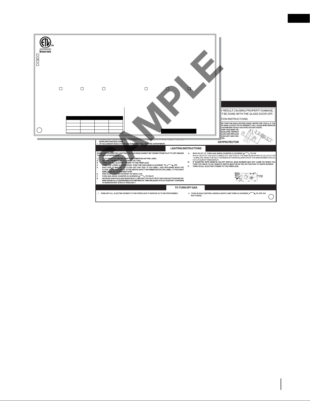
1.3 rating plate information
TITLE: RATING PLATE GVFL18 / 24 / 30
DWG#: W385-0317
DATE: 08.31.05 REVISION: M: Updated to ANSI Z21.11.2-2019, added ETL website II 02.23.21_
WOLF STEEL LTD.
24 NAPOLEON ROAD. BARRIE, ONTARIO L4M 0G8 CANADA
W385-0317 / M
CERTIFIED TO: ANSI Z21.11.2-2019 UNVENTED HEATERS
ANSI Z21.60-2017 / CSA 2.26-2017 DECORATIVE GAS APPLIANCES FOR INSTALLATION IN SOLID-FUEL BURNING FIREPLACES
REMOVAL OF THIS MARKING WILL VOID THE COMPLIANCE OF THIS HEATER WITH ANSI Z21.11.2.
STATE OR LOCAL CODES MAY ONLY ALLOW OPERATION OF THIS APPLIANCE IN A VENTED CONFIGURATION. CHECK YOUR STATE OR LOCAL CODES.
WARNING: IMPROPER INSTALLATION, ADJUSTMENT, ALTERATION, SERVICE OR MAINTENANCE CAN CAUSE PROPERTY DAMAGE, PERSONAL INJURY OR LOSS OF LIFE.
REFER TO THE OWNER’S INFORMATION MANUAL PROVIDED WITH THIS APPLIANCE. FOR ASSISTANCE OR ADDITIONAL INFORMATION, CONSULT A QUALIFIED INSTALLER,
SERVICE AGENCY OR THE GAS SUPPLIER. THIS APPLIANCE IS NOT FIELD CONVERTIBLE FOR USE WITH OTHER GASES.
WARNING: THIS APPLIANCE IS FOR INSTALLATION ONLY IN A SOLID-FUEL BURNING MASONRY OR UL 127 FACTORY-BUILT FIREPLACE OR IN A LISTED VENTLESS
FIREBOX ENCLOSURE. IT HAS BEEN DESIGN CERTIFIED FOR THESE INSTALLATIONS. EXCEPTION: DO NOT INSTALL THIS APPLIANCE IN A FACTORY-BUILT FIREPLACE THAT
INCLUDES INSTRUCTIONS STATING THAT IT HAS NOT BEEN TESTED OR SHOULD NOT BE USED WITH UNVENTED GAS LOGS.
WARNING: DO NOT ADD ANY MATERIAL TO THE APPLIANCE, WHICH WILL COME IN CONTACT WITH THE FLAMES, OTHER THAN THAT SUPPLIED BY THE MANUFACTURER
WITH THE APPLIANCE.
WARNING: FAILURE TO POSITION THE PARTS IN ACCORDANCE WITH THESE DIAGRAMS OR FAILURE TO USE ONLY PARTS SPECIFICALLY APPROVED WITH THIS HEATER
MAY RESULT IN PROPERTY DAMAGE OR PERSONAL INJURY. SEE MANUAL FOR FURTHER INFORMATION.
WARNING: DO NOT USE A BLOWER INSERT, HEAT EXCHANGER INSERT, OR OTHER ACCESSORY NOT APPROVED FOR USE WITH THIS HEATER.
WARNING: ANY GLASS DOORS SHALL BE COMPLETELY OPENED WHEN THE APPLIANCE IS IN OPERATION.
CAUTION: HOT WHILE IN OPERATION. DO NOT TOUCH. KEEP CHILDREN, CLOTHING, FURNITURE, GASOLINE AND OTHER LIQUIDS HAVING FLAMMABLE VAPOURS AWAY.
FOR YOUR SAFETY: DO NOT STORE OR USE GASOLINE OR OTHER FLAMMABLE VAPORS AND LIQUIDS IN THE VICINITY OF THIS OR ANY APPLIANCE.
9700539 (WSL)
4001657 (NGZ)
4001658 (NAC)
4001659 (WUSA)
NATURAL GAS MODELS PROPANE MODELS
GVFL18N GVFL24N GVFL30N GVFL18P GVFL24P GVFL30P
40,000 BTU/h 40,000BTU/h 40,000 BTU/h INPUT 40,000 BTU/h 40,000 BTU/h 40,000BTU/h
24,000 BTU/h 24,000 BTU/h 24,000 BTU/h REDUCED INPUT 33,000 BTU/h 33,000 BTU/h 33,000 BTU/h
0-2000FT (0-1370m) ALTITUDE 0-2000FT (0-1370m)
3.5” WATER COLUMN MANIFOLD PRESSURE 10” WATER COLUMN
4.5” WATER COLUMN MINIMUM SUPPLY PRESSURE 11” WATER COLUMN
7.0” WATER COLUMN MAXIMUM SUPPLY PRESSURE 13” WATER COLUMN
#820637 SIT CONTROL #820636
#8411824 OPERATING PILOT OXYPROTECTOR #84118438
WHEN INSTALLING INTO A SOLID FUEL BURNING FIREPLACE:
THE FIREPLACE CHIMNEY MUST HAVE A PERMANENT VENT OPENING TO ATMOSPHERE OF NOT
LESS THAN 33.8” FOR GVFL18, 33.8” FOR GVFL24, 33.8” FOR GVFL30 OR AS DETERMINED BY THE
MANUFACTURER’S INSTALLATION INSTRUCTIONS.
MINIMUM FIREPLACE SIZE
UNIT HEIGHT WIDTH DEPTH
GVFL18 18” 24” 14”
GVFL24 18” 28” 14”
GVFL30 18” 34” 14”
FOR MINIMUM CHIMNEY
FLUE, SEE INSTRUCTION
MANUAL.
WHEN INSTALLING INTO A LISTED VENTLESS FIREBOX ENCLOSURE FOR
GAS-FIRED UNVENTED DECORATIVE ROOM HEATER:
AS A GAS FIRED UNVENTED ROOM HEATER, THIS UNIT REQUIRES ADEQUATE COMBUSTION AND
VENTILATION AIR FOR SAFE OPERATION. THIS TYPE OF INSTALLATION IS NOT APPROVED FOR
BEDROOMS, BATHROOMS AND BED SITTING ROOMS. KEEP BURNER AND CONTROL AREA
CLEAN.
SERIAL NUMBER:
GVFL
M
TITLE: RATING PLATE GVFL18 / 24 / 30
REVISION: M: Updated to ANSI Z21.11.2-2019, added ETL website II 02.23.21_
DWG#: W385-0317
DATE: 08.31.05
Refer to the Intertek Directory of Building Products (https://bpdirectory.intertek.com) for detailed information
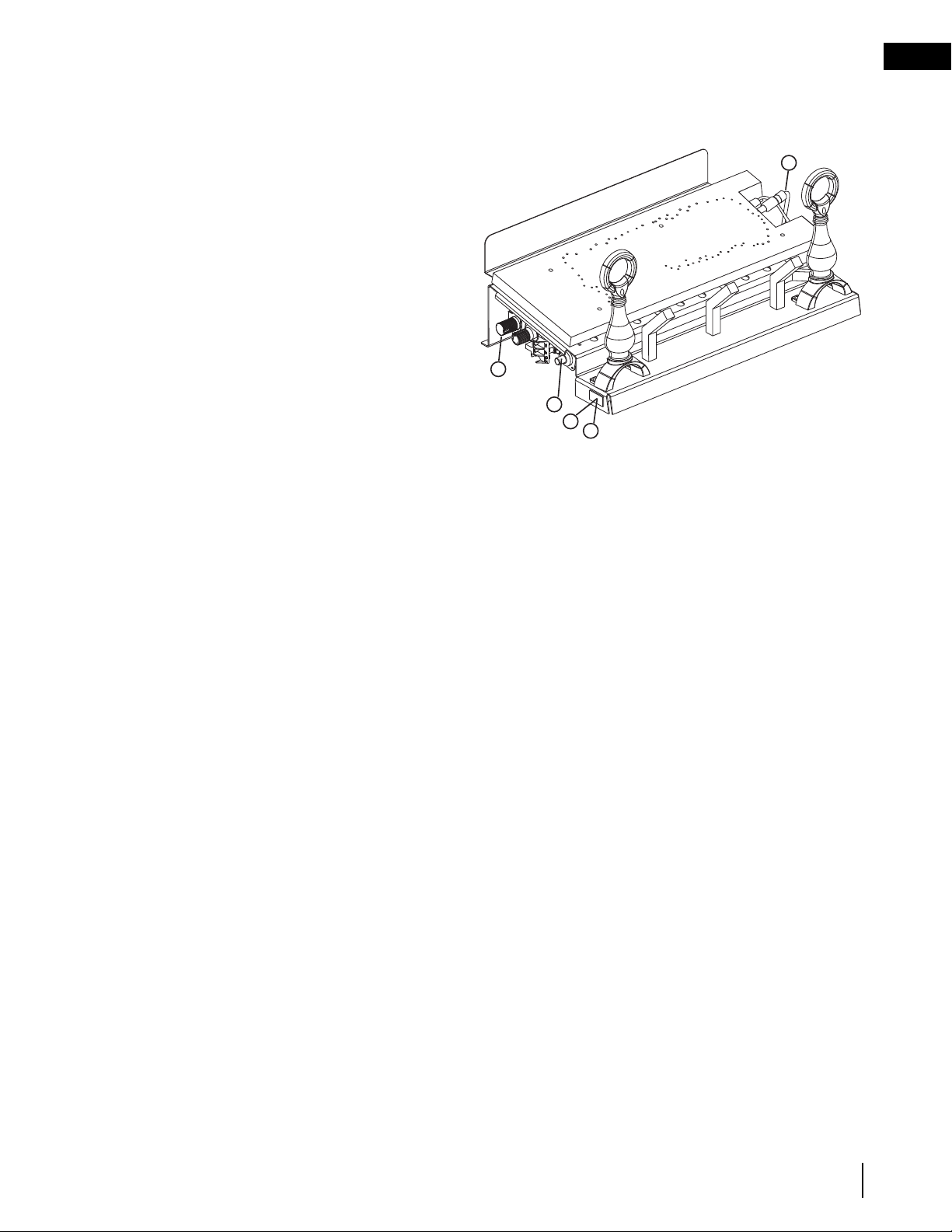
THE RATING PLATE IS CHAINED TO THE PIEZO IGNITOR BRACKET AND SHOULD BE TUCKED
UNDER THE ENTIRE ASSEMBLY
This illustration is for reference only. Refer to the rating plate on the appliance for accurate information.
SAMPLE
W415-0809 / D / 02.26.21
EN
8
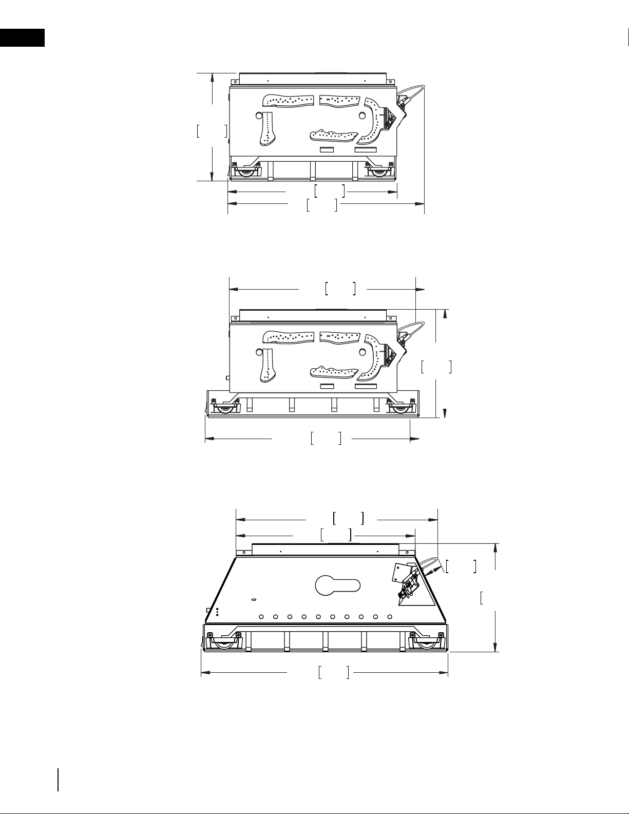
dimensions
GVFL24 ILLUSTRATED
24"
610mm
13 1/4"
336mm
26 1/4"
667mm
GVFL18 ILLUSTRATED
13 1/4"
336mm
20 1/2"
521mm
24"
610mm
GVFL30 ILLUSTRATED
24"
610mm
22 3/4"
578mm
13 1/4"
336mm
1 1/2"
38mm
30 1/4"
768mm
2.0 dimensions
GVFL18
GVFL24
GVFL30

EN
W415-0809 / D / 02.26.21
9
installation
3.0 installation
The GVFL 18/24/30 are all rated at 40,000 BTUs per hour and therefore requires a minimum unconfined space of
2,000 cubic feet.
During manufacturing, fabricating and shipping various components of this appliance are treated with certain oils,
films or bonding agents.
These materials may produce smoke and smells as they are burned off during the initial operation of the
appliance; possibly causing headaches or eye or lung irritation. This is a normal and temporary occurrence. Simply
open a window to ventilate the room during the burn off period.
3.1 installation in an unvented application
3.1.1 combustion and ventilation air provisions
3.1.2 determining confined or unconfined space
!
WARNING
• Barriers such as the bottom of a glass door frame placed in front of a gas log set can change the air flow
characteristics of the appliance which in turn can cause the appliance to carbon or overheat and malfunction.
15.1
This appliance shall not be installed in a confi ned space or unusually tight construction unless provisions are provided for
adequate combustion and ventilation air.
The National Fuel Gas Code, ANSI Z223.1 / NFPA 54 defi nes a confi ned space as a space whose volume is less than 50
cubic feet per 1,000 Btu per hour (4.8 m3 per kw) of the aggregate input rating of all appliances installed in that space
and an unconfi ned space as a space whose volume is not less than 50 cubic feet per 1,000 Btu per hour (4.8 m3 per
kw) of the aggregate input rating of all appliances installed in that space. Rooms communicating directly with the space
in which the appliances are installed, through openings not furnished with doors are considered a part of the unconfi ned
space.
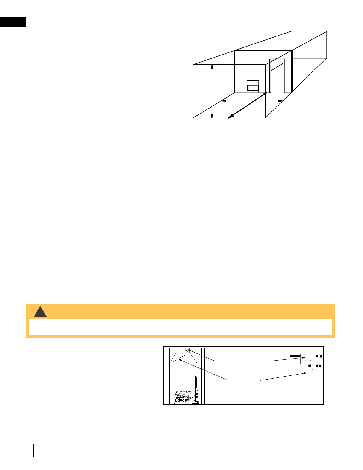
To determine the volume of the room where the appliance is to be installed, multiply the width x the length x the ceiling
height of that room measured in feet. If any adjoining rooms are connected by grilles or openings such as kitchen pass-
throughs, etc., the volume of those rooms may be added to the total.
Multiply the room volume by 1000 and divide this amount by 50 to determine the maximum BTU/hr that the space can
support with adequate combustion and ventilation air.
Add the Btu/hr of all fuel burning appliances located within the space such as gas furnace, gas water appliance, etc.
Do not include direct vent gas appliances which draw their input air from the outdoors and expel their exhaust to the
outdoors.
Unusually tight construction is defi ned as construction where:
A) Walls and ceilings exposed to the outside atmosphere have a continuous water vapour retarder with a rating of 1
perm (6 x 10-11 kg per pa-sec-m2) or less with openings gasketed or sealed
B) Weather stripping has been added on openable windows and doors
C) Caulking or sealants are applied to areas such as joints around window and door frames, between sole plates and
fl oors, between wall-ceiling joints, between wall panels, at penetrations for plumbing, electrical, and gas lines, and at
other openings.
An unvented room appliance is recommended for use as a secondary heat source rather than as a primary source. Gas
combustion produces water vapour which could occur at the rate of approximately one ounce of water for every 1,000
BTU/hr of gas input. During the cold weather season, indoor humidity levels tend to be low. Consequently, this water
vapour can enhance the living space. However if a problem should occur:
A) Ensure suffi cient combustion and circulation air
B) Use a dehumidifi er
C) Do not use the unvented room appliance as a primary heat
source. Without suffi cient fresh air for proper operation, poor fuel
combustion can result. Carbon Monoxide is a result of poor fuel
combustion.
If additional fresh air is required, use one of the methods
described in the National Fuel Gas Code, ANSI Z223.1 / NFPA54
or the applicable local code.
Room Volume = Length x Width x Height
Max BTU/hr = Room Volume x 1000 / 50
If for example:
The length of the rooms is 5 feet (1.5m),
The width of Room 1 is 10 feet (3.1m),
The width of Room 2 is 15 feet (4.6m),
The height of the rooms is 8 feet (2.4m).
Volume of Room 1: 5x10x8 = 400 cubic feet (11.16 cubic meters)
Volume of Room 2: 5x15x8 = 600 cubic feet (16.56 cubic meters)
EXAMPLE 1:
In this example, because there is no door to the adjoining room, the volume of the adjoining room may be added to the
volume of the room with the heater to get a total unconfi ned space.
The total unconfi ned space: 400 ft
3
(11.3m
3
)+ 600 ft
3
(17m
3
) = 1000 cubic feet (28.3m
3
).
Maximum BTU/h: [(1000x1000) ÷ 50] = 20,000 BTU/h
EXAMPLE 2:
If in this example a solid door separates Room 1 from Room 2, the volume of Room 2 could not be used. In this case the
maximum BTU/h would be:
Maximum BTU/h: [(400x1000) ÷50] = 8,000 BTU/h
HEIGHT
ROOM 1
ROOM 2
WIDTH
LENGTH
• If the area in which the appliance may be operated is smaller than that defi ned as an unconfi ned space or if
the building is of unusually tight construction, provide adequate combustion and ventilation air by one of the
methods described in the National Fuel Gas Code ANSI Z223.1 / NFPA 54, air for combustion and ventilation,
or the applicable local code.
• If the area in which the appliance may be operated does not meet the required volume for indoor combustion
air, combustion and ventilation air shall be provided by one of the methods described in the ANSI Z223.1 /
NFPA 54, the International Fuel Gas Code, or applicable local codes.
!
WARNING
15.1
This appliance shall not be installed in a confi ned space or unusually tight construction unless provisions are provided for
adequate combustion and ventilation air.
The National Fuel Gas Code, ANSI Z223.1 / NFPA 54 defi nes a confi ned space as a space whose volume is less than 50
cubic feet per 1,000 Btu per hour (4.8 m3 per kw) of the aggregate input rating of all appliances installed in that space
and an unconfi ned space as a space whose volume is not less than 50 cubic feet per 1,000 Btu per hour (4.8 m3 per
kw) of the aggregate input rating of all appliances installed in that space. Rooms communicating directly with the space
in which the appliances are installed, through openings not furnished with doors are considered a part of the unconfi ned
space.
To determine the volume of the room where the appliance is to be installed, multiply the width x the length x the ceiling
height of that room measured in feet. If any adjoining rooms are connected by grilles or openings such as kitchen pass-
throughs, etc., the volume of those rooms may be added to the total.
Multiply the room volume by 1000 and divide this amount by 50 to determine the maximum BTU/hr that the space can
support with adequate combustion and ventilation air.
Add the Btu/hr of all fuel burning appliances located within the space such as gas furnace, gas water appliance, etc.
Do not include direct vent gas appliances which draw their input air from the outdoors and expel their exhaust to the
outdoors.
Unusually tight construction is defi ned as construction where:
A) Walls and ceilings exposed to the outside atmosphere have a continuous water vapour retarder with a rating of 1
perm (6 x 10-11 kg per pa-sec-m2) or less with openings gasketed or sealed
B) Weather stripping has been added on openable windows and doors
C) Caulking or sealants are applied to areas such as joints around window and door frames, between sole plates and
fl oors, between wall-ceiling joints, between wall panels, at penetrations for plumbing, electrical, and gas lines, and at
other openings.
An unvented room appliance is recommended for use as a secondary heat source rather than as a primary source. Gas
combustion produces water vapour which could occur at the rate of approximately one ounce of water for every 1,000
BTU/hr of gas input. During the cold weather season, indoor humidity levels tend to be low. Consequently, this water
vapour can enhance the living space. However if a problem should occur:
A) Ensure suffi cient combustion and circulation air
B) Use a dehumidifi er
C) Do not use the unvented room appliance as a primary heat
source. Without suffi cient fresh air for proper operation, poor fuel
combustion can result. Carbon Monoxide is a result of poor fuel
combustion.
If additional fresh air is required, use one of the methods
described in the National Fuel Gas Code, ANSI Z223.1 / NFPA54
or the applicable local code.
Room Volume = Length x Width x Height
Max BTU/hr = Room Volume x 1000 / 50
If for example:
The length of the rooms is 5 feet (1.5m),
The width of Room 1 is 10 feet (3.1m),
The width of Room 2 is 15 feet (4.6m),
The height of the rooms is 8 feet (2.4m).
Volume of Room 1: 5x10x8 = 400 cubic feet (11.16 cubic meters)
Volume of Room 2: 5x15x8 = 600 cubic feet (16.56 cubic meters)
EXAMPLE 1:
In this example, because there is no door to the adjoining room, the volume of the adjoining room may be added to the
volume of the room with the heater to get a total unconfi ned space.
The total unconfi ned space: 400 ft
3
(11.3m
3
)+ 600 ft
3
(17m
3
) = 1000 cubic feet (28.3m
3
).
Maximum BTU/h: [(1000x1000) ÷ 50] = 20,000 BTU/h
EXAMPLE 2:
If in this example a solid door separates Room 1 from Room 2, the volume of Room 2 could not be used. In this case the
maximum BTU/h would be:
Maximum BTU/h: [(400x1000) ÷50] = 8,000 BTU/h
HEIGHT
ROOM 1
ROOM 2
WIDTH
LENGTH
• If the area in which the appliance may be operated is smaller than that defi ned as an unconfi ned space or if
the building is of unusually tight construction, provide adequate combustion and ventilation air by one of the
methods described in the National Fuel Gas Code ANSI Z223.1 / NFPA 54, air for combustion and ventilation,
or the applicable local code.
• If the area in which the appliance may be operated does not meet the required volume for indoor combustion
air, combustion and ventilation air shall be provided by one of the methods described in the ANSI Z223.1 /
NFPA 54, the International Fuel Gas Code, or applicable local codes.
!
WARNING
W415-0809 / D / 02.26.21
EN
10
installation
If there are no more fuel burning appliances within this space then the 40,000 BTU/h input of the appliance is suit-
able to be installed. This also assumes that the construction of this space is not unusually tight.
This would be considered a confined space since it can not support the 40,000 BTU/h input of the appliance and
it would be necessary to provide adequate combustion and ventilation air to Room 1.
15.1
This appliance shall not be installed in a confi ned space or unusually tight construction unless provisions are provided for
adequate combustion and ventilation air.
The National Fuel Gas Code, ANSI Z223.1 / NFPA 54 defi nes a confi ned space as a space whose volume is less than 50
cubic feet per 1,000 Btu per hour (4.8 m3 per kw) of the aggregate input rating of all appliances installed in that space
and an unconfi ned space as a space whose volume is not less than 50 cubic feet per 1,000 Btu per hour (4.8 m3 per
kw) of the aggregate input rating of all appliances installed in that space. Rooms communicating directly with the space
in which the appliances are installed, through openings not furnished with doors are considered a part of the unconfi ned
space.
To determine the volume of the room where the appliance is to be installed, multiply the width x the length x the ceiling
height of that room measured in feet. If any adjoining rooms are connected by grilles or openings such as kitchen pass-
throughs, etc., the volume of those rooms may be added to the total.
Multiply the room volume by 1000 and divide this amount by 50 to determine the maximum BTU/hr that the space can
support with adequate combustion and ventilation air.
Add the Btu/hr of all fuel burning appliances located within the space such as gas furnace, gas water appliance, etc.
Do not include direct vent gas appliances which draw their input air from the outdoors and expel their exhaust to the
outdoors.
Unusually tight construction is defi ned as construction where:
A) Walls and ceilings exposed to the outside atmosphere have a continuous water vapour retarder with a rating of 1
perm (6 x 10-11 kg per pa-sec-m2) or less with openings gasketed or sealed
B) Weather stripping has been added on openable windows and doors
C) Caulking or sealants are applied to areas such as joints around window and door frames, between sole plates and
fl oors, between wall-ceiling joints, between wall panels, at penetrations for plumbing, electrical, and gas lines, and at
other openings.
An unvented room appliance is recommended for use as a secondary heat source rather than as a primary source. Gas
combustion produces water vapour which could occur at the rate of approximately one ounce of water for every 1,000
BTU/hr of gas input. During the cold weather season, indoor humidity levels tend to be low. Consequently, this water
vapour can enhance the living space. However if a problem should occur:
A) Ensure suffi cient combustion and circulation air
B) Use a dehumidifi er
C) Do not use the unvented room appliance as a primary heat
source. Without suffi cient fresh air for proper operation, poor fuel
combustion can result. Carbon Monoxide is a result of poor fuel
combustion.
If additional fresh air is required, use one of the methods
described in the National Fuel Gas Code, ANSI Z223.1 / NFPA54
or the applicable local code.
Room Volume = Length x Width x Height
Max BTU/hr = Room Volume x 1000 / 50
If for example:
The length of the rooms is 5 feet (1.5m),
The width of Room 1 is 10 feet (3.1m),
The width of Room 2 is 15 feet (4.6m),
The height of the rooms is 8 feet (2.4m).
Volume of Room 1: 5x10x8 = 400 cubic feet (11.16 cubic meters)
Volume of Room 2: 5x15x8 = 600 cubic feet (16.56 cubic meters)
EXAMPLE 1:
In this example, because there is no door to the adjoining room, the volume of the adjoining room may be added to the
volume of the room with the heater to get a total unconfi ned space.
The total unconfi ned space: 400 ft
3
(11.3m
3
)+ 600 ft
3
(17m
3
) = 1000 cubic feet (28.3m
3
).
Maximum BTU/h: [(1000x1000) ÷ 50] = 20,000 BTU/h
EXAMPLE 2:
If in this example a solid door separates Room 1 from Room 2, the volume of Room 2 could not be used. In this case the
maximum BTU/h would be:
Maximum BTU/h: [(400x1000) ÷50] = 8,000 BTU/h
HEIGHT
ROOM 1
ROOM 2
WIDTH
LENGTH
• If the area in which the appliance may be operated is smaller than that defi ned as an unconfi ned space or if
the building is of unusually tight construction, provide adequate combustion and ventilation air by one of the
methods described in the National Fuel Gas Code ANSI Z223.1 / NFPA 54, air for combustion and ventilation,
or the applicable local code.
• If the area in which the appliance may be operated does not meet the required volume for indoor combustion
air, combustion and ventilation air shall be provided by one of the methods described in the ANSI Z223.1 /
NFPA 54, the International Fuel Gas Code, or applicable local codes.
!
WARNING
3.2 installing in a vented application
The appliance and gas logs function as a system. If the appliance is not drafting properly and spilling into the
room (check with a match or a smoke stick), reposition the damper clamp until a positive draft is obtained
by opening the damper. If negative pressure in home prevents having a positive draft, consult an air quality
specialist.
3.2.1 damper stop installation
The damper must be permanently locked in
position to prevent full closure and to provide
a minimum flue opening. Various methods for
locking the damper may be used but may be
restricted from region to region and it is important
to know the specifics that apply to your area.
For your convenience a damper stop is provided
with the appliance and may be used where not
prohibited by state or local codes.
!
WARNING
• Before installing in a solid fuel burning fireplace, the chimney and firebox must be cleaned of soot, creosote,
ashes and loose paint by a qualified chimney cleaner.
DAMPER STOP
DAMPER
EN
W415-0809 / D / 02.26.21
11
installation
MINIMUM DAMPER OPENING
(SQUARE INCHES)
CHIMNEY
HEIGHT
MASONRY
APPLIANCE
FACTORY BUILT
APPLIANCE
6
33.8”
8
31.2”
10
28.7” 22.1”
15
26.1” 17.3”
20
23.7” 14.5”
25
22.7” 12.6”
30
21.6” 11.3”
35
10.8”
40
10.2”
Use the 3” adjustable bolt to adjust the damper to the
correct opening, based on the enclosed chart.
Should the damper stop not fit, or provide the required
permanent opening from the Minimum Damper
Opening table, have the damper cut to provide a
minimum permanent opening or install an alternate
stop.
Any outside air ducts and/or ash dumps in the
appliance shall be permanently closed at time of
appliance installation.
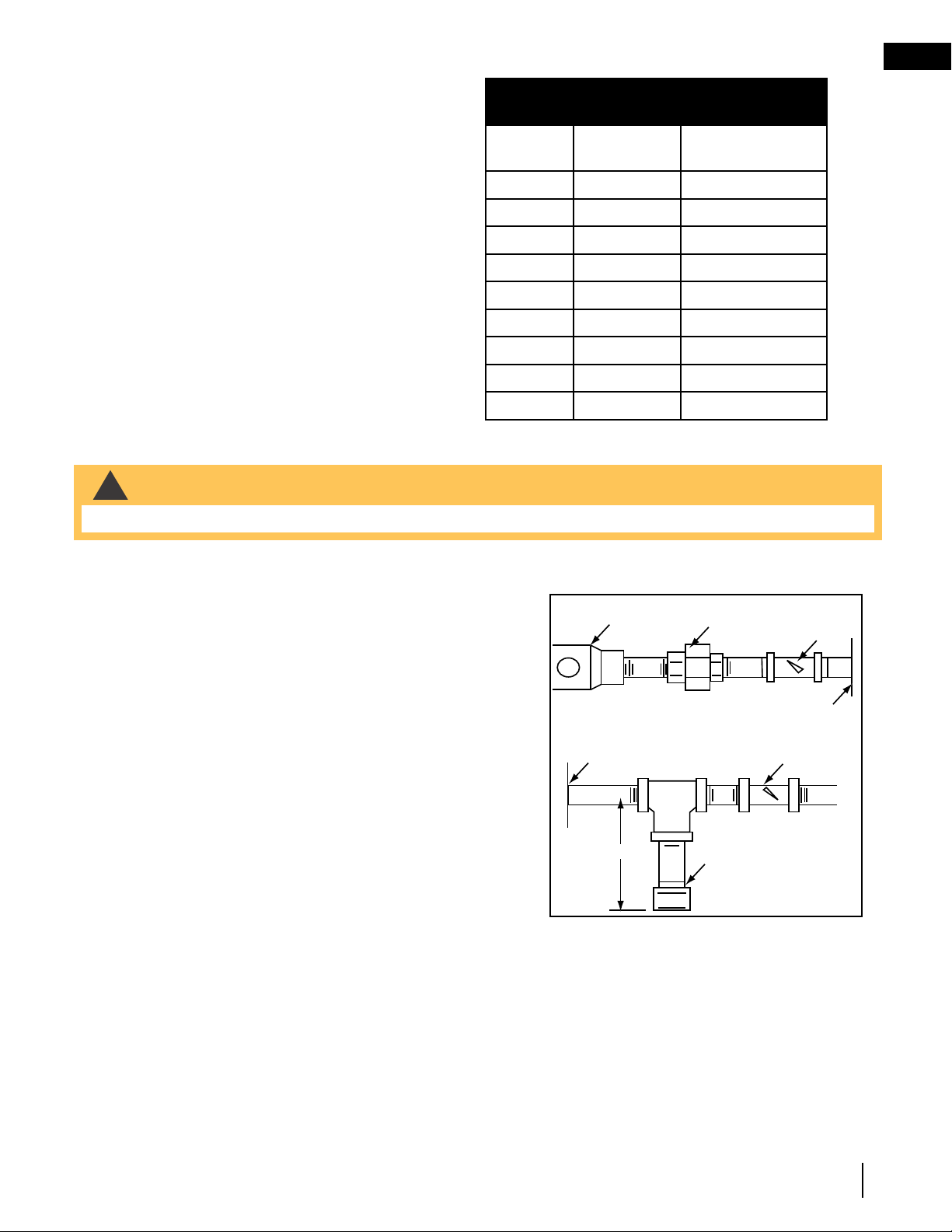
3.3 gas piping
This appliance and it’s appliance main valve must be disconnected from the gas supply piping system during any
pressure testing of that system at test pressures in excess of ½ PSI (3.5kPa)
This appliance must be isolated from the gas supply piping system
by closing the individual manual shut off valve during any pressure
testing of the gas supply piping system at test pressure equal to or
less than ½ psi (3.5 kPa)
A. Centre the appliance in the appliance opening, making
sure the appliance has enough room behind it for the gas
line to run behind the log set under the log support.
B. Route the gas line and sizing using piping ½” diameter or
greater to allow the full volume of gas to the appliance.
The routing of the gas line has to be done to local and / or
national codes.
C. When rigid pipe is used an ANSI approved manual shut
off and a union must be installed upstream within the
appliance cavity.
D. To ensure the appliance operates reliably install a sediment
trap upstream of the appliance within the structures of the piping system.
E. When using propane, a regulator must be used between the tank and the outside wall of the house to
ensure the line pressure does not exceed 14” w.c.
F. Check gas connections with a gas detection device to test for leaks in the system. Soapy water mixture
can also be used to check for leaks.
G. Once all the gas connections are tested for leaks, start the appliance. Follow the lighting instructions to
ensure the appliance is working properly before finishing.
Regulator
Union
Manual
Shut-Off
Valve
Wall
Shut-Off
Key
Sediment
Trap
Appliance
Appliance
3" (76.3mm)
!
WARNING
• Do not connect either the wall switch, thermostat or gas valve to electricity (110 volts).
W415-0809 / D / 02.26.21
EN
12
finishing
4.0 finishing
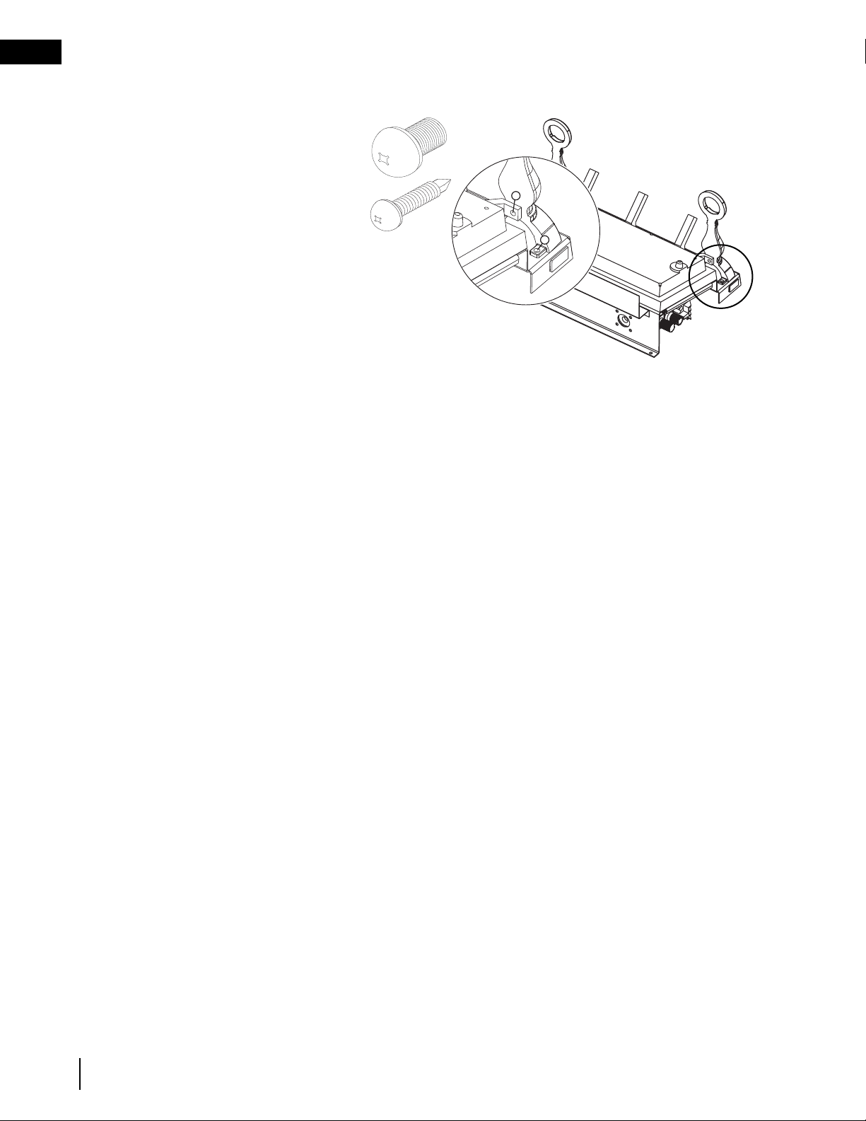
4.1 andiron and grate assembly
A. With the 2 andirons laying face down,
secure the grate overtop using 2x
¼-20 bolts (supplied in the manual
baggie).
B. Install the grate/andiron assembly
to the burner base using 4x ¾” self
tapping screws (supplied in the
manual baggie).
1
2
USE ONLY ACCESSORIES
DESIGNED FOR AND
LISTED WITH YOUR
SPECIFIC LOG SET.
EN
W415-0809 / D / 02.26.21
13
finishing
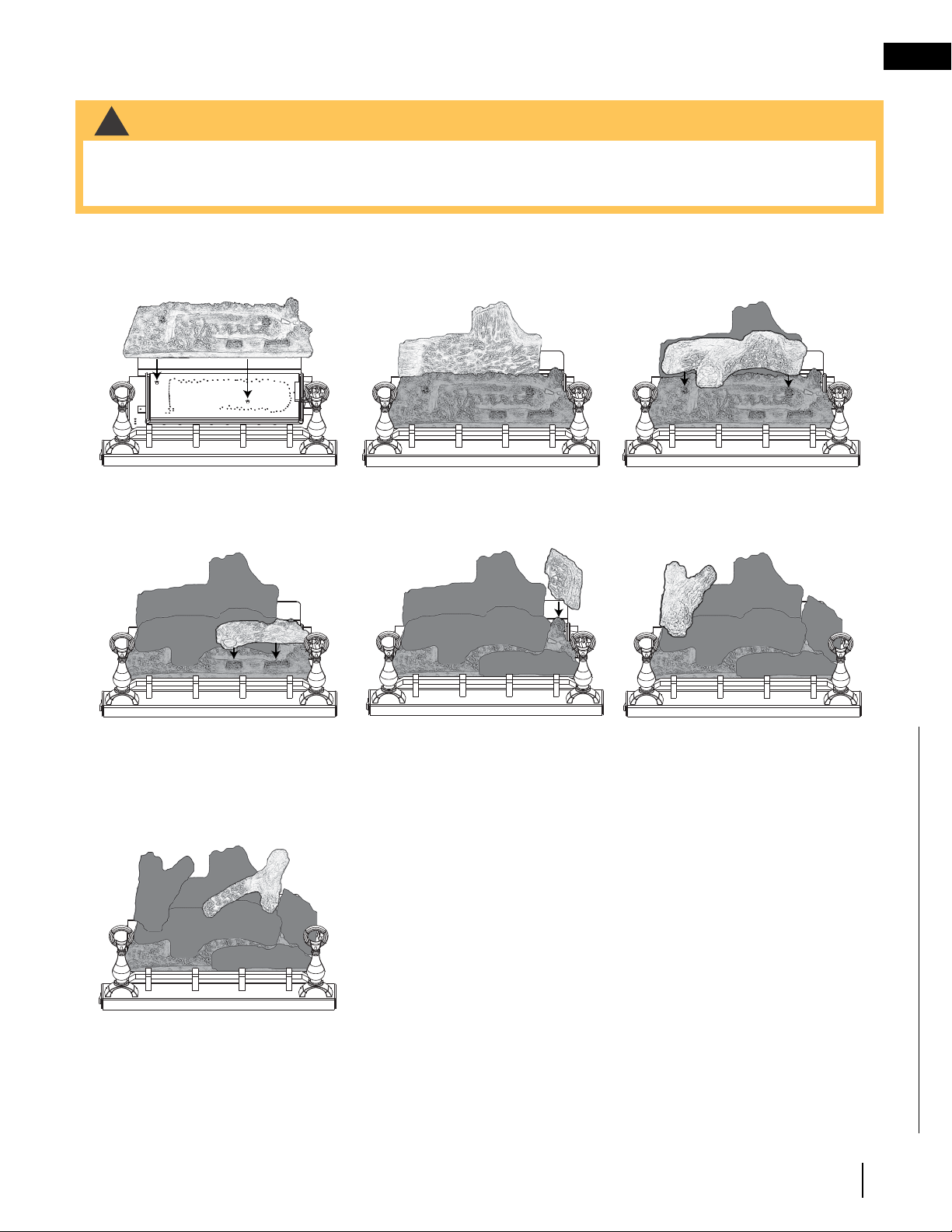
4.2 log placement
Phazer
TM
logs, exclusive to Napoleon, provide a unique and realistic glowing effect that is different in every installa-
tion. These logs are fuel specific. Do not interchange. Refer to the replacement parts list.
Failure to follow these log placement instructions may cause sooting.
B. Place the rear log #1 onto
the locating studs on the
rear log support.
C. Position the holes on the
bottom of log #2 onto the
fibre embosses shown.
D. Position the slotted
cavities on the bottom of
log #6 onto the slotted
projections shown. The
charred face should be
facing in.
E. Position the bottom cavity
of log #3 onto the bridge
(top right corner of fibre
burner cover) as shown,
with the charred face
inward.
F. Position the pins on the
bottom of log #4 into the
holes on the left end of
log #1 and the left end of
log #2.
G. Place the end of log #5
on the right end of log
#1. The fork in the log
should straddle the knot
on top of the log #2.
Log colours may vary. During the initial use of the appliance, the colours
will become more uniform as colour pigments burn in during the heat
activated curing process.
Positioning the logs improperly will cause flame impingement and car-
boning.
Blocked burner ports can cause an incorrect flame pattern, carbon de-
posits and delayed ignition. Phazer
TM
logs glow when exposed to direct
flame. Use only certified Phazer
TM
logs available from your authorized
dealer/distributor.
A. Place the fibre burner
cover onto the two locat-
ing studs screwed into the
pan burner.
!
WARNING
• Failure to position these logs in accordance with these diagrams or failure to use parts specifically approved
with this appliance may result in property damage or personal injury.
• Do not place glowing embers, charcoal embers, vermiculite or charcoal lumps on this burner.
W415-0809 / D / 02.26.21
EN
14
finishing
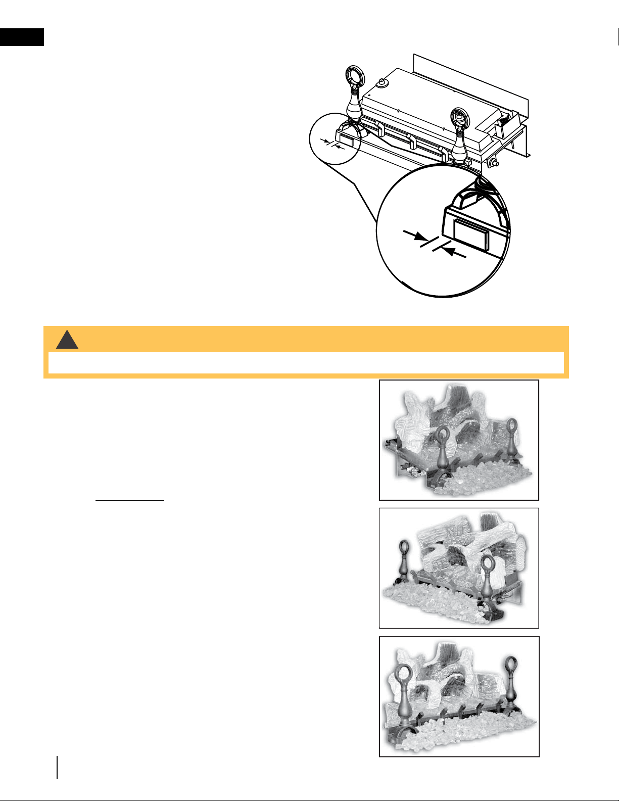
4.3 logo placement
LOGO
½"
LOGO
½"
LOGO
½"
LOGO
½"
Remove the backing of the logo supplied. Centre the logo
on the front of the appliance, ½” in from the left side, as
shown.
4.4 media
A. Place lava or ember rock around the base of the appliance,
making sure not to block any burner ports or valve access.
Retain a small amount of lava rock for step 3 and if
applicable step 4.
B. Place formed charcoal lumps around the front and sides of
the appliance.
C. Use remaining lava or ember rock to blend with the
charcoal lumps.
D. GVFL30 ONLY: Sprinkle remaining lava rock onto the outer
fibre ember beds to hide the seam.
GVFL18
GVFL24
GVFL30
!
WARNING
• All previously applied loose material must be removed prior to reapplication
EN
W415-0809 / D / 02.26.21
15
operating instructions
5.0 operating instructions
If the appliance is equipped with decorative glass doors, they must be fully opened when operating this gas log
set.
5.1 lighting instructions
A
C
D
E
B
A. Locate the pilot burner at the rear of the log set on the right
side.
B. Turn the gas control knob to the pilot setting
(on the left side of the appliance closest to the
back).
C. With the control knob depressed, push the
piezo igniter continuously until the pilot lights.
Hold the control knob in for 1 minute and
release. If the pilot goes out, repeat steps B and
C.
D. Once the pilot stays burning, make certain
that the on / off switch is in the off position.
Turn the control knob counter-clockwise to the on
position.
E. Turn the on / off switch to the on position to ignite the burner. This
appliance must be isolated from the gas supply piping system by closing the individual manual shut off
valve during any pressure testing of the gas supply piping system at test pressure equal to or less than ½
psi (3.5 kPa).
If appliance shuts off, do not relight until you provide fresh air. If appliance keeps shutting off, have it serviced.
Keep burner and control compartment clean.
When lit for the first time, the appliance will emit a slight odour for a few hours. This is a normal temporary condi-
tion caused by the curing of the logs and the “burn-off” of internal paints and lubricants used in the manufacturing
process and will not occur again. Open a window to ventilate the room during this burn off period.
5.2 match lighting instructions
A. Remove any items necessary for easy access to the ODS (for example: logs, screens, etc.).
B. Follow appropriate lighting instructions found previously. Instead of pushing and releasing the piezo but-
ton, light a match and hold the flame to the end of the pilot and ignite the pilot.
C. After control knob has been released and pilot stays lit, reinstall any items that were removed for pilot
access.
D. Call a qualified service technician for repair or replacement of the piezo ignitor.
After extended periods of non-operation such as following a vacation or a warm weather season, the appliance
may emit a slight odour for a few hours. This is caused by dust particles burning off. In both cases, open a win-
dow to sufficiently ventilate the room.
Purge the gas line with the glass door open. Assure that a continuous gas flow is at the burner before closing the
door.
W415-0809 / D / 02.26.21
EN
16
operation
6.0 operation
31.1A
!
WARNING
• Do not turn on if children or other at risk individuals are near the appliance.
• This appliance is equipped with a pilot which must be lit by hand while following these instructions exactly.
• Before operating, smell all around the appliance area for gas and next to the fl oor because some gas is heavier
than air and will settle on the fl oor.
• Use only your hand to turn the gas control knob. Never use tools. If the knob will not turn by hand, do not try
to repair it. Call a qualifi ed service technician. Force or attempted repair may result in a fi re or explosion.
• Do not use this appliance if any part has been under water. Immediately call a qualifi ed service technician
to inspect the appliance and replace any part of the control system and any gas control which has been
underwater.
FOR YOUR SAFETY READ BEFORE LIGHTING
WHAT TO DO IF YOU SMELL GAS
LIGHTING INSTRUCTIONS
TO TURN OFF GAS
A. Stop! Read the above safety information on this label.
B. Remove batteries from the transmitter and set thermostat to lowest setting, if equipped.
C. Turn off all electrical power to the appliance.
D. Open the glass door, if equipped.
E. Turn the gas knob clockwise to the “OFF” position.
F. Wait fi ve (5) minutes to clear out any gas. If you smell gas including near the fl oor, STOP!
Follow the instructions above in the “WHAT TO DO IF YOU SMELL GAS” section. If you
don’t smell gas; close the glass door and go to the next step.
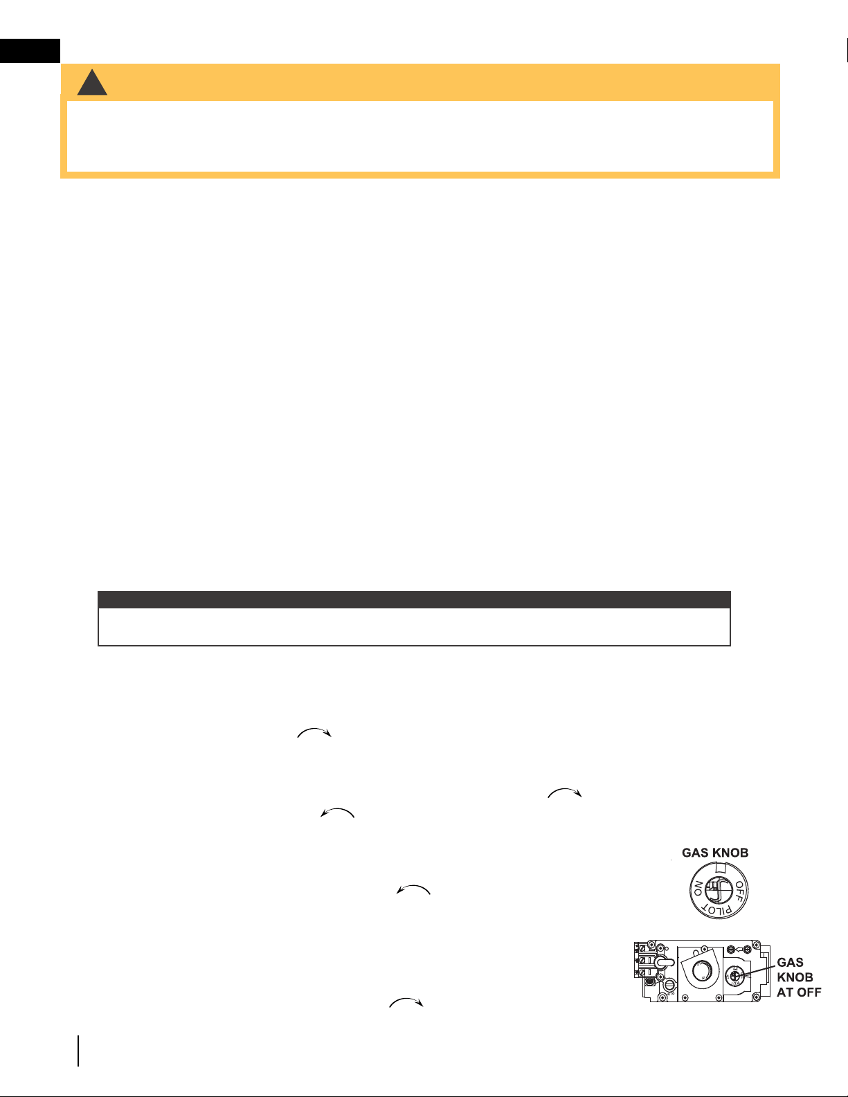
G. If the appliance is equipped with fl ame adjustment valve turn clockwise to “OFF”.
H. Turn gas knob counter-clockwise to the “PILOT” position. (If the appliance is equipped
with an “ON/OFF” switch, ensure it is in the “ON” position.
I. Depress and hold gas knob while lighting the pilot with the push button ignitor. Keep knob
fully depressed for one minute, then release. If pilot does not continue to burn, repeat steps
E through I.
J. With pilot lit, turn gas knob counter-clockwise
to the “ON” position.
K. If equipped with the fl ame adjustment valve, push and turn the knob to high.
L. Turn on all electrical power to the appliance and re-install the batteries into the transmitter, if
equipped. Set thermostat to desired setting, if equipped.
A. Set thermostat to desired setting, if equipped.
B. Turn off all electrical power to the appliance if service is to be performed.
C. Push in gas knob slightly and turn clockwise to the “OFF” position. Do not force.
• Turn off all gas to the appliance.
• Open windows.
• Do not try to light any appliance.
• Do not touch any electric switch; do not use
any phone in your building
• Immediately call your gas supplier from a
neighbour’s phone. Follow the gas supplier’s
instructions.
• If you cannot reach your gas supplier, call
the fi re department.
• If you do not follow these instructions exactly, a fi re or explosion may result causing property damage, personal
injury, or loss of life.
• If applicable, always light the pilot whether for the fi rst time or if the gas supply has run out with the glass door
opened or removed.
add gas knob
add gas valve
Ensure that a continuous gas fl ow is at the burner before installing the door. When lit for the fi rst time, the appliance
will emit an odor for a few hours. This is a normal temporary condition caused by the “burn-in” of paints and
lubricants used in the manufacturing process and will not occur again. After extended periods of non-operation
such as following a vacation or a warm weather season, the appliance may emit a slight odor for a few hours. This
is caused by dust particles in the heat exchanger burning off. In both cases, open a window to suffi ciently ventilate
the room.
For vent free appliances ONLY: if the appliance shuts off, do not relight until you provide fresh air. If appliance
keeps shutting off, have it serviced. Keep burner and control compartment clean.
note:
When lighting and re-lighting, the gas knob cannot be turned from pilot to off unless the knob is
depressed.
31.1A
add gas valve
When lighting and re-lighting, the gas knob cannot be turned from pilot to off unless the knob is depressed.
Wait five (5) minutes to clear out any gas. If you smell gas including near the floor, STOP! Follow “B” in the above safety information
31.1A
add gas valve
When lighting and re-lighting, the gas knob cannot be turned from pilot to off unless the knob is depressed.
Wait five (5) minutes to clear out any gas. If you smell gas including near the floor, STOP! Follow “B” in the above safety information
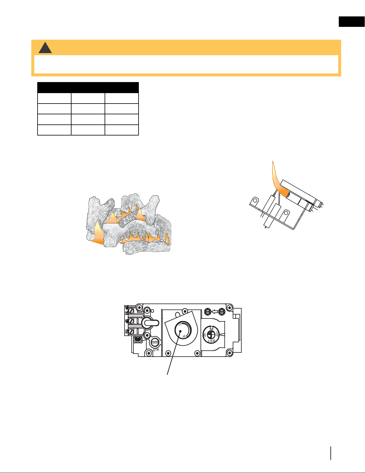
EN
W415-0809 / D / 02.26.21
17
adjustments
It’s important to periodically perform a visual check of
the pilot and burner flames. Compare them to the
illustration provided. If any flames appear abnormal,
call a service person.
ADD IMAGE
HERE
36.1
7.0 adjustments
7.1 air shutter
LOG SET AIR SHUTTER
FUEL NG P
GVFL18 9/32” 7/16”
GVFL24 9/32” 7/16”
GVFL30 9/32” 7/16”
The air shutter settings are factory set for most installations. However,
adjustment may be required depending on fuel type, vent performance
and altitude.
Closing the air shutter will cause a more yellow flame, but can lead to
carboning. Opening the air shutter will cause a more blue flame, but
can cause flame lifting from the burner ports. The flame may not appear
yellow immediately; allow 15 to 30 minutes for the final flame colour to be
established.
7.2 flame characteristics
!
WARNING
• Carbon can be distributed in surrounding living areas if the air shutter is improperly adjusted.
• Failure to keep the primary air opening(s) of the burneer(s) clean may result in sooting and property damage.
La flamme doit envelopper
la sonde de flamme de
3/8" à 1/2"
(9.5mm - 12.7mm)
Flame must envelop
upper
3/8" to 1/2"
(12.7mm - 9.5mm) of
Flame sensor
DEXEN EI 2-WAY PILOT
DEXEN EI
ODS - MILLIVOLT
3/8” - 1/2”
(9.5mm - 12.7mm)
Flame must envelop
upper
3/8" to 1/2"
(12.7mm - 9.5mm) of
thermocouple
3/8” - 1/2”
(9.5mm - 12.7mm)
La flamme doit envelopper
la thermocouple de 3/8" à
1/2"
(9.5mm - 12.7mm)
PSE THERMOCOUPLE
Flame must envelop
upper
3/8" to 1/2"
(12.7mm - 9.5mm) of
Flame sensor
SIT ELECTRONIC IGNITION
3/8” - 1/2”
(9.5mm - 12.7mm)
3/8” - 1/2”
(9.5mm - 12.7mm)
3/8” - 1/2”
(9.5mm - 12.7mm)
3/8” - 1/2”
(9.5mm - 12.7mm)
La flamme doit envelopper
la sonde de flamme de
3/8" à 1/2"
(9.5mm - 12.7mm)
3/8” - 1/2”
(9.5mm - 12.7mm)
Flame must envelop
upper
3/8" to 1/2"
(12.7mm - 9.5mm) of
thermocouple &
thermopile
3/8” - 1/2”
(9.5mm - 12.7mm)
La flamme doit
envelopper la
thermocouple et
thermopile
de 3/8" à 1/2"
(9.5mm - 12.7mm)
SIT MILLIVOLT
3/8” - 1/2”
(9.5mm - 12.7mm)
Flame must envelop
upper
3/8" to 1/2"
(12.7mm - 9.5mm) of
thermocouple
La flamme doit envelopper
la thermocouple de 3/8" à
1/2"
(9.5mm - 12.7mm)
PSE LONG SENSOR
3/8” - 1/2”
(9.5mm - 12.7mm)
7.3 flame height adjustment
The adjustment is made by turning the Hi/Lo knob. The “Hi” setting corresponds to the maximum pressure to the
burner and “Lo” corresponds to the minimum pressure. Actuation of this knob is independent from the actuation
of the ON/OFF control.
Hi / Lo Knob
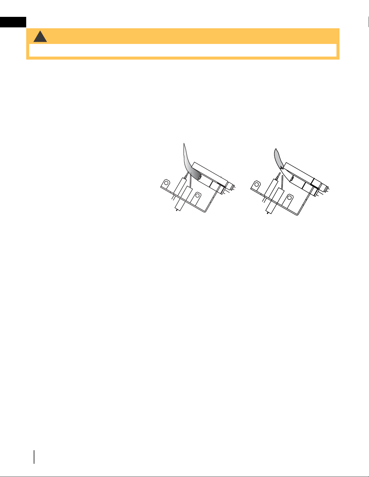
W415-0809 / D / 02.26.21
EN
18
maintenance
This procedure must be performed by a qualified
service person!
Inspect the pilot for any visible contamination or
debris (usually lint, pet hair, spider webs, carpet
fibre, etc.) and remove.
Disconnect the pilot from the pilot tubing line,
using the appropriate wrench. Blow out the
housing in the same direction as the gas flow.
Re-install the pilot tube, turn on the gas and
check for leaks.
If this does not improve the performance, replace
the ODS with an exact replacement. The device is
tamper resistant with no field serviceable parts.
CORRECT PILOT FLAME
Flame contacts thermocouple
correctly (clean, stable and
pronounced blue flame).
INCORRECT PILOT FLAME
Flame lifts off thermocouple
(flame becomes unstable with
more of an orange tip).
30.1
ADD IMAGE
HERE
TURN OFF THE GAS AND ELECTRICAL POWER BEFORE SERVICING THE APPLIANCE.
8.0 maintenance
8.1 oxygen depletion sensor (ODS) cleaning
Visually inspect the appliance for carbon buildup.
Using a small whisk or brush, brush off the excess carbon and vacuum up or sweep into the garbage.
Check the appliance for broken logs and corrosion of the main burner base.
!
WARNING
• Turn off the gas and electrical power before servicing the appliance.
HOUSING

EN
W415-0809 / D / 02.26.21
19
replacement parts
9.0 replacement parts
!
WARNING
26.1
• Failure to position the parts in accordance with this manual or failure to use only parts specifi cally approved
with this appliance may result in property damage or personal injury.
Contact your dealer for questions concerning prices and policies on replacement parts. Normally, all parts can
be ordered through your Authorized dealer / distributor.
For warranty replacement parts, a photocopy of the original invoice will be required to honour the
claim.
When ordering replacement parts always give the following information:
• Model & Serial Number of appliance
• Installation date of appliance
• Part number
• Description of part
• Finish
Parts, part numbers, and availability are subject to change without notice.
Parts identifi ed as stocked will be delivered within 2 to 5 business days for most delivery
destinations.
Parts not identifi ed as stocked will be delivered within a 2 to 4 week period, for most cases.
Parts identifi ed as ‘SO’ are special order and can take up to 90 days for delivery.

W415-0809 / D / 02.26.21
EN
20
replacement parts
COMPONENTS
REF NO. PART NO. DESCRIPTION
1 W135-0205 #1 - REAR LOG
2 W135-0206 #2 - MIDDLE LOG
3 W135-0413 #6 - FRONT LOG
4 W135-0207 #3 - RIGHT LOG
5 W135-0208 #4 - LEFT CROSSOVER LOG
6 W135-0218 #5 - RIGHT CROSSOVER LOG
7 GL-671 LOG SET
8 W185-0024 GVFL18 GRATE
8 W185-0020 GVFL24 GRATE
8 W185-0023 GVFL30 GRATE
9 W715-0628 GVFL18 / 24 ANDIRONS
9 W715-0629 GVFL30 ANDIRONS
10 W357-0001 PIEZO IGNITOR AND NUT
11 W456-0032 #32 ORIFICE - NG
11 W456-0050 #50 ORIFICE - LP
12 W660-0023 ON / OFF SWITCH
13 W725-0030 VALVE - NG
13 W725-0031 VALVE - LP
14* W385-0334 NAPOLEON LOGO
15 W662-0003 NATURAL GAS - OXYGEN DEPLETION SENSOR
15 W662-0004 PROPANE GAS - OXYGEN DEPLETION SENSOR
16 W135-0394 FIBRE BURNER COVER
17 W010-2120 WELDED BURNER ASSEMBLY
18* W550-0006 LAVA ROCK
19* W550-0002 CHARCOAL LUMPS
20 W010-1288 DAMPER STOP
21* W750-0060 IGNITOR CABLE
22* W720-0093 PILOT TUBE
23* W135-0265 GVFL30 RIGHT EXTENSION LOG
24* W135-0266 GVFL30 LEFT EXTENSION LOG
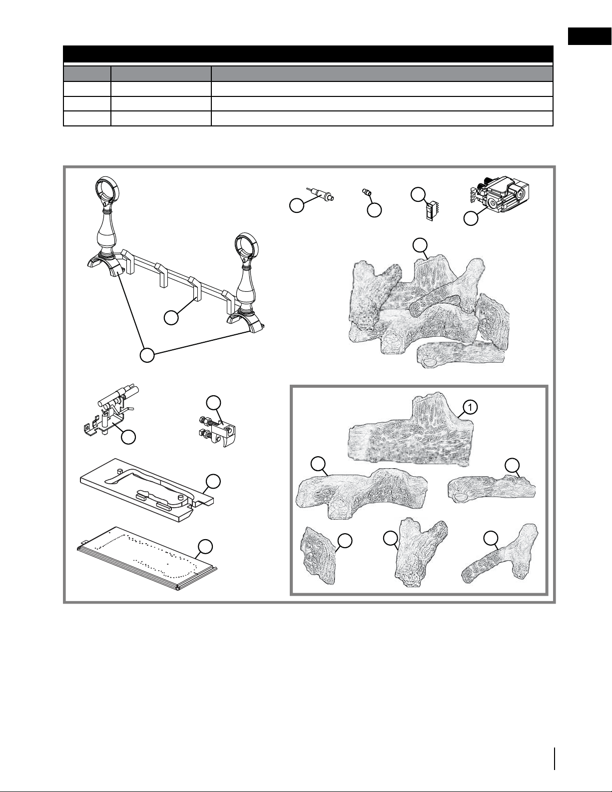
EN
W415-0809 / D / 02.26.21
21
accessories
ACCESSORIES
REF NO. PART NO. DESCRIPTION
25* GD-660 REMOTE WALL SWITCH W/20” WIRE
26* W660-0026 PROGRAMMABLE TIMER
27* W550-0006 ADDITIONAL LAVA ROCK / CINDERS
10.0 accessories
7
2
1
3
6
13
12
8
10
11
9
20
15
1
4 5
16
17
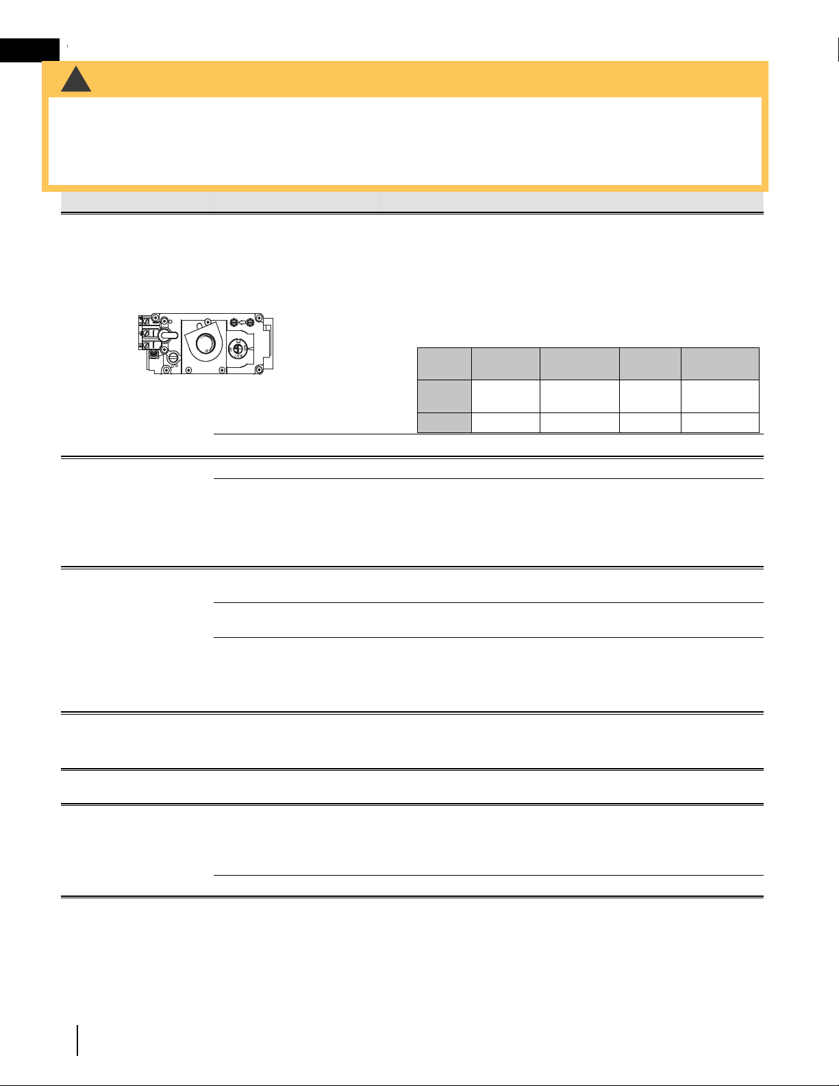
W415-0809 / D / 02.26.21
EN
22
troubleshooting
11.0 troubleshooting
27.4
symptom problem test solution
Flames are consistently too
large or too small.
Carboning occurs.
Appliance is over-fi red or
underfi red.
- Check pressure readings:
Inlet pressure can be checked by turning screw (A) counter-clockwise
2 or 3 turns and then placing pressure gauge tubing over the test
point. Gauge should read as described on the chart below. Check that
main burner is operating on ‘HI’. Outlet pressure can be checked the
same as above using screw (B). Gauge should read as described on
the chart below. Check that main burner is operating on ‘HI’. AFTER
TAKING PRESSURE READINGS, BE SURE TO TURN SCREWS
CLOCKWISE FIRMLY TO RESEAL. DO NOT OVER TORQUE.
Leak test with a soap and water solution.
Air shutter improperly adjusted. - Return air shutter to specifi ed opening, see “venturi adjustment” section.
Carbon is being deposited
on glass, logs, rocks,
media or combustion
chamber.
Air shutter has become blocked. - Ensure air shutter opening is free of lint or other obstructions.
Flame is impinging on the
glass, logs, rocks, media or
combustion chamber.
- Check that the logs are correctly positioned.
- Check for ceiling or oscillating fans that may be infl uencing the fl ame.
- Open air shutter to increase the primary air. See “venturi adjustment”
section.
- Check the input rate: check the manifold pressure and orifi ce size as
specifi ed by the rating plate.
Exhaust fumes smelled in
room, headaches.
Not enough combustion air. - Increase fresh air supply. (Use one of the methods described in ANSI
Z223.1 / NFPA 54 or the applicable local code.)
Not enough ventilation air. - Increase fresh air supply. (Use one of the methods described in ANSI
Z223.1 / NFPA 54 or the applicable local code.)
Flame is impinging on the logs or
combustion chamber.
- Check that the logs are correctly positioned.
- Open air shutter to increase the primary air. See “venturi adjustment”
section.
- Check the input rate: check the manifold pressure and orifi ce size as
specifi ed by the rating plate values.
Main burner will not light;
or is slow to light, noisy
pilot.
Inlet pressure too high. - Adjust inlet pressure to ensure 7.0” W.C. (17.4mb) at gas valve for
natural gas and 13.0” W.C. (32.4mb) for propane.
Pilot fl ame blowing off, missing
thermopile.
Pilot is not functioning
properly.
Pilot has been painted - Using a piece of sandpaper or emery cloth remove the paint from the
pilot hood, ignitor and fl ame sensor.
Pilot goes out while
standing; Main burner is in
‘OFF’ position.
Gas piping is undersized. - Turn on all gas appliances and see if pilot fl ame fl utters, diminishes or
extinguishes, especially when main burner ignites. Monitor appliance
supply working pressure.
- Check if supply piping size is to code.
- Correct all undersized piping.
Pilot fl ame is not large enough. - ODS Burner requires checking.
INSERT
PHOTO
OF VALVE
HERE
Pressure
Natural Gas
(inches)
Natural Gas
(millibars)
Propane
(inches)
Propane
(millibars)
Inlet
* 7”
(MIN. 4.5”)
17.4mb
(MIN. 11.2mb)
13”
(MIN. 11”)
32.4mb
(MIN. 27.4mb)
Outlet
3.5” 8.7mb 10” 24.9mb
* Maximum inlet
pressure not to
exceed 13”
• Always light the pilot whether for the fi rst time or if the gas supply has run out with the glass door open or removed.
• Turn off the appliance completely and let cool before servicing. Only a qualifi ed service person should service and
repair this electric appliance.
• Appliance may be hot, do not service until appliance has cooled.
• Do not use abrasive cleaners.
!
WARNING

EN
W415-0809 / D / 02.26.21
23
troubleshooting
symptom problem test solution
Pilot will not light. Out of propane gas. - Fill the tank.
No spark at pilot burner. - Check if pilot can be lit by a match.
- Check that the wire is connected to the push button ignitor.
- Check if the push button ignitor needs tightening.
- Replace the wire if the wire insulation is broken or frayed.
- Replace the electrode if the ceramic insulator is cracked or broken.
- Replace the push button ignitor.
No gas at the pilot burner. - Check that the manual valve is turned on.
- Check the pilot orifi ce for blockage.
- Replace the valve / Oxygen Depletion Sensor System.
- Call the gas distributor.
Pilot burning; no gas to
main burner; gas knob
is on ‘HI’; wall switch /
thermostat is on.
Thermostat or switch is
defective.
- Connect a jumper wire across the wall switch terminals; if main burner
lights, replace switch / thermostat.
Wall switch wiring is defective. - Disconnect wires from valve. Connect a jumper wire across terminals
1 & 3; if the main burner lights, check the wires for defects and / or
replace wires.
Main burner orifi ce is plugged. - Remove stoppage in orifi ce.
Faulty valve. - Replace.
Pilot goes out when the
gas knob is released.
The gas valve has an
interlock device which
will not allow the pilot
burner to be lit until
the thermocouple
has cooled. Allow
approximately 60
seconds for the
thermocouple to cool.
System is not correctly purged. - Purge the gas line.
Out of propane gas. - Fill the tank.
Pilot fl ame is not large enough.
(Supply pressure too low.)
- Service or replace Oxygen Depletion Sensor System.
- Correct piping and / or regulator to provide correct pressure.
- Ensure adequate supply pressure.
Thermocouple shorting / faulty. - Loosen and tighten thermocouple.
- Clean thermocouple and valve connection.
- Replace Oxygen Depletion Sensor System.
- Test and replace valve.
Faulty valve / high low knob
does not depress smoothly.
- Replace.
Main burner goes out;
pilot stays on.
Pilot fl ame is not large enough
or not engulfi ng the thermopile.
- Ensure adequate supply pressure.
- Replace pilot assembly.
Thermopile shorting / loose
connection.
- Clean thermopile connection to the valve. Reconnect.
- Replace thermopile / valve.
Remote wall switch wire is too
long; too much resistance in the
system.
- Shorten wire to connect length or wire gauge.
Faulty thermostat or switch. - Replace.
Main burner goes out;
pilot goes out.
Insuffi cient air supply. - Open window or door. (Use one of the methods described in ANSI
Z223.1 / NFPA54 or the applicable local code.)
- Have room checked for adequate air exchange.
- See “combustion and ventilation air provisions” section to ensure
adequate air supply.
Out of propane gas. - Fill the tank.
Pilot fl ame is not large enough.
(Supply pressure too low.)
- Service or replace Oxygen Depletion Sensor System.
Remote wall switch is
in “off” position; main
burner comes on when
gas knob is turned to
“ON” position.
Wall switch mounted upsidedown.
- Reverse.
Wall switch is grounding. - Replace.
Wall switch wire is grounding. - Check for ground (short); repair ground or replace wire.
Faulty valve. - Replace.
INSERT
PHOTO
OF PILOT
HERE
27.4_2
HOUSING

W415-0809 / D / 02.26.21
EN
24
warranty
12.0 warranty
2.1C
Napoleon warrants its products against manufacturing defects to the original purchaser only. Registering your warranty is
not necessary. Simply provide your proof of purchase along with the model and serial number to make a warranty claim.
Napoleon reserves the right to have its representative inspect any product or part thereof prior to honouring any warranty
claim. Provided that the purchase was made through an authorized Napoleon dealer your appliance is subject to the
following conditions and limitations:
Warranty coverage begins on the date of original installation. This factory warranty is non-transferable and may not
be extended whatsoever by any of our representatives. The gas appliance must be installed by a licensed, authorized
service technician or contractor qualifi ed and authorized installer, service agency or supplier. Installation must be done in
accordance with the installation instructions included with the product and all local and national building and fi re codes.
This limited warranty does not cover damages caused by misuse, lack of maintenance, accident, alterations, abuse or
neglect, and parts installed from other manufacturers will nullify this warranty. This limited warranty further does not cover
any scratches, dents, corrosion or discoloring caused by excessive heat, abrasive and chemical cleaners nor chipping
on porcelain enamel parts, mechanical breakage of Phazer™ logs and embers. This warranty extends to the repair or
replacement of warranted parts which are defective in material or workmanship provided that the product has been
operated in accordance with the operation instructions and under normal conditions. After the fi rst year, with respect to
this President’s Lifetime Limited Warranty, Napoleon may, at its discretion, fully discharge all obligations with respect to this
warranty by refunding to the original warranted purchaser the wholesale price of any warranted but defective part(s).
After the fi rst year, Napoleon will not be responsible for installation, labour, or any other expenses related to the reinstallation
of a warranted part and such expenses are not covered by this warranty. Notwithstanding any provisions contained in the
President’s Lifetime Limited Warranty, Napoleon’s responsibility under this warranty is defi ned as above and it shall not in
any event extend to any incidental, consequential or indirect damages. This warranty defi nes the obligations and liability
of Napoleon with respect to the Napoleon gas appliance and any other warranties expressed or implied with respect to
this product, its components or accessories are excluded. Napoleon neither assumes, nor authorizes any third party to
assume, on its behalf, any other liabilities with respect to the sale of this product. Napoleon will not be responsible for: over-
fi ring, downdrafts, spillage caused by environmental conditions such as rooftops, buildings, nearby trees, hills, mountains,
inadequate vents or ventilation, excessive venting confi gurations, insuffi cient makeup air, or negative air pressures which
may or may not be caused by mechanical systems such as exhaust fans, furnaces, clothes dryers, etc. Any damages to
the appliance, combustion chamber, heat exchanger, plated trim or other components due to water, weather damage, long
periods of dampness, condensation, damaging chemicals or cleaners will not be the responsibility of Napoleon.
During the fi rst 10 years Napoleon will replace or repair the defective parts covered by the lifetime warranty at our
discretion free of charge. From 10 years to life, Napoleon will provide replacement parts at 50% of the current retail price.
The manufacturer may require that defective parts or products be returned or that digital pictures be provided to support
the claim. Returned products are to be shipped prepaid to the manufacturer for investigation. If a product is found to be
defective, the manufacturer will repair or replace such defect. Before shipping your appliance or defective components,
your dealer must obtain an authorization number. Any merchandise shipped without authorization will be refused and
returned to sender. Shipping costs are not covered under this warranty. Additional service fees may apply if you are
seeking warranty service from a dealer. Warranty labour allowance is only for the replacement of the warranted part. Travel,
diagnostic tests, shipping and other related charges are not covered by this warranty.
Napoleon products are manufactured under the strict Standard of the world recognized ISO 9001 : 2015 Quality Management
System.
Napoleon products are designed with superior components and materials assembled by trained craftsmen who take great
pride in their work. The burner and valve assembly are leak and test-fi red at a quality test station. The complete appliance is
again thoroughly inspected by a qualifi ed technician before packaging to ensure that you, the customer, receive the quality
product that you expect from Napoleon.
The following materials and workmanship in your new Napoleon gas appliance are warranted against defects for as long
as you own the appliance. This covers: combustion chamber, heat exchanger, stainless / steel burner, Phazer™ logs
and embers, rocks, ceramic glass (thermal breakage only), gold plated parts against tarnishing, porcelainized enameled
components and aluminum extrusion trims.*
Electrical (110V and millivolt) components and wearable parts are covered and Napoleon will provide replacement parts free
of charge during the fi rst year of the limited warranty. This covers: blowers, gas valves, thermal switches, switches, wiring,
remote controls, ignitors, gaskets and pilot assemblies.*
Labour related to warranty repair is covered free of charge during the fi rst year (labour warranty is not applicable for the Gas
Log Sets). Repair work, however, requires the prior approval of an authorized company offi cial. Labour costs to the account
of Napoleon are based on a predetermined rate schedule and any repair work must be done through an authorized
Napoleon dealer.
* Construction of models vary. Warranty applies only to components included with your specifi c appliance.
Napoleon Gas Appliance President’s Lifetime Limited Warranty
Conditions and Limitations
All specifi cations and designed are subject to change without prior notice due to on-going product improvements. Napoleon is a registered
trademark of Wolf Steel Ltd.

EN
W415-0809 / D / 02.26.21
25
service history
Appliance Service History
This appliance must be serviced annually depending on usage.
Date Dealer Name Service Technician Name Service Performed Special Concerns
13.0 service history

W415-0809 / D / 02.26.21
EN
26
notes
29.1

EN
W415-0809 / D / 02.26.21
27
notes
29.1
NAPOLEON CELEBRATING OVER 40 YEARS
OF HOME COMFORT PRODUCTS
7200, Route Transcanadienne, Montréal, Québec H4T 1A3
24 Napoleon Road, Barrie, Ontario, Canada L4M 0G8
214 Bayview Drive, Barrie, Ontario, Canada L4N 4Y8
103 Miller Drive, Crittenden, Kentucky, USA 41030
Phone: 1-866-820-8686
napoleon.com
De Riemsdijk 22, 4004 LC Tiel, The Netherlands