Loading ...
Loading ...
Loading ...
www.dimplex.de 452237.66.02 · FD 9506 EN7
English
SI 50TU - SI 75TU
7.4.2 Mounting the outside
temperature sensor
The temperature sensor must be mounted in such a way that all
weather conditions are taken into consideration and the meas-
ured value is not falsified.
Mount on the external wall on the north or north-west side
where possible
Do not install in a “sheltered position" (e.g. in a wall niche or
under a balcony)
Not in the vicinity of windows, doors, exhaust air vents, ex-
ternal lighting or heat pumps
Not to be exposed to direct sunlight at any time of year
Sensor lead: Max. length 40 m; min. core cross-section
0.75 mm²; external diameter of the cable 4-8 mm.
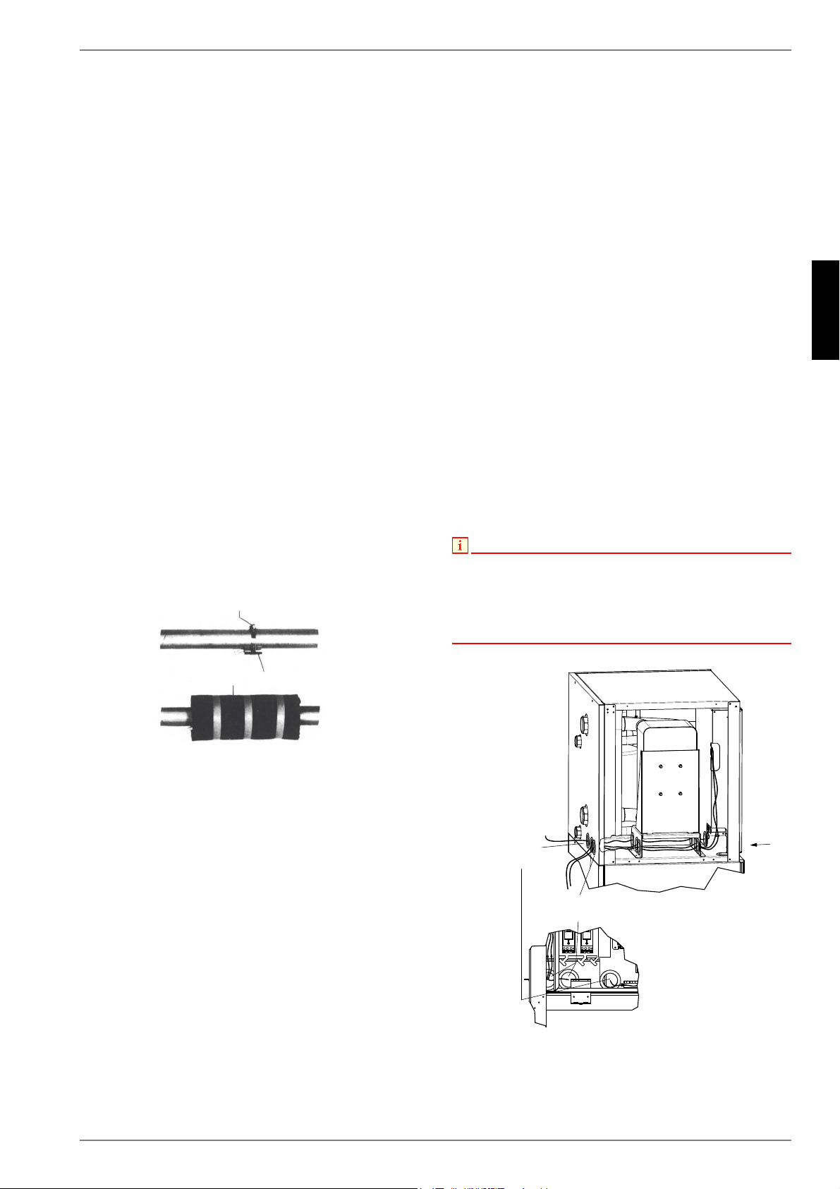
7.4.3 Installing the strap-on sensor
It is only necessary to mount the strap-on sensors if they are in-
cluded in the scope of supply of the heat pump but have not yet
been installed.
The strap-on sensors can be fitted as pipe-mounted sensors or
installed in the immersion sleeve of the compact manifold.
Mounting as a pipe-mounted sensor
Remove paint, rust and scale from heating pipe.
Coat the cleaned surface with heat transfer compound (ap-
ply sparingly).
Attach the sensor with a hose clip (tighten firmly, as loose
sensors can cause malfunctions) and thermally insulate.
7.4.4 Hydraulic distribution system
The compact manifold and the dual differential pressureless
manifold function as an interface between the heat pump, the
heating distribution system, the buffer tank and, in some cases,
even the domestic hot water cylinder. A compact system is used
to simplify the installation process, so that a lot of different com-
ponents do not have to be installed individually. Further informa-
tion can be found in the relevant installation instructions.
Compact manifold
The return sensor can remain in the heat pump, or should be in-
stalled in the immersion sleeve. The remaining empty space be-
tween the sensor and the immersion sleeve must be filled com-
pletely with heat transfer compound.
Dual differential pressureless manifold
In order for the heating circuit pumps of the generator and con-
sumer circuits to supply the flow to the return sensor, this must
be installed in the immersion sleeve of the dual differential pres-
sureless manifold.
7.5 Electrical connection
7.5.1 General
All electrical installation work must be carried out by a trained
electrician or a specialist for the specified tasks in accordance
with the
installation and operating instructions,
country-specific installation regulations (e.g. VDE 0100),
technical connection conditions of the energy suppliers and
supply grid operators (e.g. TAB) and
local conditions.
To ensure that the frost protection function of the heat pump
works properly, the heat pump manager must remain connected
to the power supply and the flow must be maintained through the
heat pump at all times.
The switching contacts of the output relay are interference-sup-
pressed. Therefore, depending on the internal resistance of the
measuring instrument, a voltage can also be measured when the
contacts are open. However, this will be much lower than the line
voltage.
Extra-low voltage is connected to controller terminals N1-J1 to
N1-J11; N1-J19 to N1-J20; N1-J23 to N1-J26 and the terminal
strips X3. If, due to a wiring error, the line voltage is mistakenly
connected to these terminals, the heat pump manager will be de-
stroyed.
NOTE
For installation work on the switch box, ensure that the mains cable and
signal cables are inserted separately into the switch box. The specially
arranged switch box inlets must be used for this purpose (see Fig.7.3 on
pag. 7).
The mains cables and signal cables must also always be laid separately
in the switch box during wiring work.
Fig. 7.3:Cable inlet switch box
+RVHFOLS
6WUDSRQVHQVRU
7KHUPDOLQVXODWLRQ
$
$
6XSSO\PDLQVFDEOH
OLQHYROWDJH
6XSSO\VLJQDOFDEOH
H[WUDORZYROWDJH
Loading ...
Loading ...
Loading ...