Loading ...
Loading ...
Loading ...
EN-6 452237.66.02 · FD 9506 www.dimplex.de
English
SI 50TU - SI 75TU
7.3 Heat source connection
The following procedure must be observed when making the
connection:
Connect the brine pipe to the heat source flow and return of the
heat pump.
The hydraulic integration diagram must be adhered to.
ATTENTION!
The supplied dirt trap must be inserted in the heat source inlet of the heat
pump to protect the evaporator against the ingress of impurities.
The brine must be produced prior to charging the system. The
brine concentration must be at least 25 %. This guarantees frost
protection up to approx. -14 °C.
Only monoethylene glycol or propylene glycol-based antifreeze
may be used.
The heat source system must be de-aerated and checked for
leaks.
ATTENTION!
The brine must contain at least a 25 % concentration of a monoethylene
glycol or propylene glycol-based antifreeze, which must be mixed before
filling.
NOTE
If necessary, the operating range can be extended to a brine inlet
temperature of -10 °C. In this case, the minimum brine concentration
must be adjusted to 30 %. (Freezing temperature -17 C°).
ATTENTION!
The maximum test pressure in the heating circuit and the brine circuit is
6.0 bar. This value must not be exceeded.
ATTENTION!
A suitable de-aerator (micro bubble air separator) must be installed in the
heat source circuit by the customer.
7.4 Temperature sensor
The following temperature sensors are already installed or must
be installed additionally:
Outside temperature sensor (R1) supplied (NTC-2)
Return temperature secondary circuit (R2) installed
(NTC-10)
Return temperature primary circuit (R24) installed (NTC-10)
Flow temperature secondary circuit (R9) installed (NTC-10)
Flow temperature primary circuit (R6) installed (NTC-10)
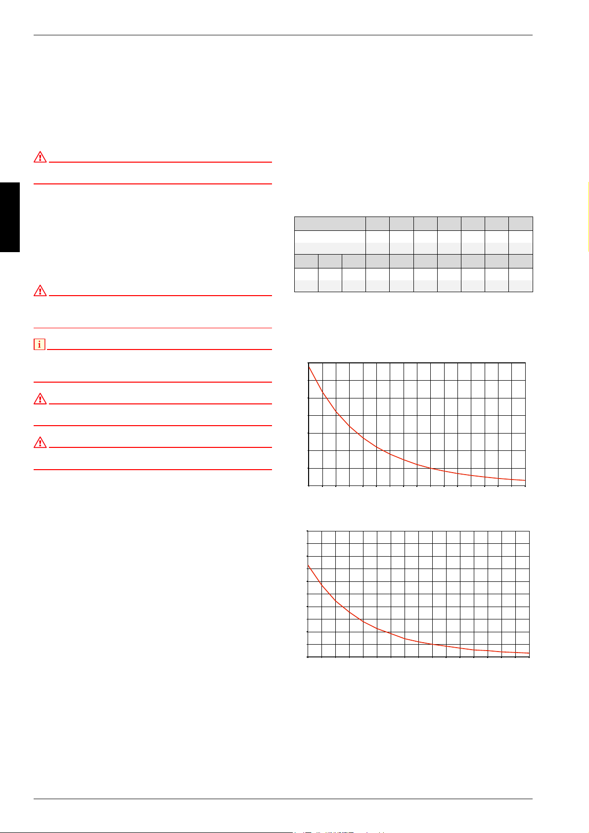
7.4.1 Sensor characteristic curves
The temperature sensors to be connected to the heat pump man-
ager must correspond to the sensor characteristic curve illus-
trated in Fig.7.1. The only exception is the outside temperature
sensor included in the scope of supply of the heat pump (see
Fig.7.2)
Fig. 7.1:Sensor characteristic curve NTC-10
Fig. 7.2:Sensor characteristic curve NTC-2 according to
DIN 44574 Outside temperature sensor
Temperature in °C
-20 -15 -10 -5 0 5 10
NTC-2 in k 14,6 11,4 8,9 7,1 5,6 4,5 3,7
NTC-10 in k 67,7 53,4 42,3 33,9 27,3 22,1 18,0
15 20 25 30 35 40 45 50 55 60
2,9 2,4 2,0 1,7 1,4 1,1 1,0 0,8 0,7 0,6
14,9 12,1 10,0 8,4 7,0 5,9 5,0 4,2 3,6 3,1
([WHUQDOWHPSHUDWXUHLQ>&@
5HVLVWDQFHYDOXHLQ>N2KP@
([WHUQDOWHPSHUDWXUHLQ>&@
5HVLVWDQFHYDOXHLQ>N2KP@
Loading ...
Loading ...
Loading ...