Loading ...
Loading ...
Loading ...
EN-4 452237.66.02 · FD 9506 www.dimplex.de
English
SI 50TU - SI 75TU
4 Accessories
4.1 Connection flange
The device can optionally be switched to flange connection using
the flat-sealing connection flange.
4.2 Remote control
A remote display adds convenience and is available as a special
accessory. Operation and menu navigation are identical to those
of the heat pump manager. Connection takes place via an inter-
face (special accessories) with RJ 12 Western plug.
NOTE
In the case of heating controllers with a removable control panel, this can
also be used directly as a remote display.
4.3 Building management system
The heat pump manager can be connected to a building man-
agement system network via supplementation of the relevant in-
terface plug-in card. The supplementary installation instructions
of the interface card must be consulted regarding the exact con-
nection and parameterisation of the interface.
The following network connections can be made on the heat
pump manager:
Modbus
EIB, KNX
Ethernet
ATTENTION!
If the heat pump or circulating pumps are controlled externally, a flow rate
switch is required to prevent the compressor from being switched on
when there is no volume flow.
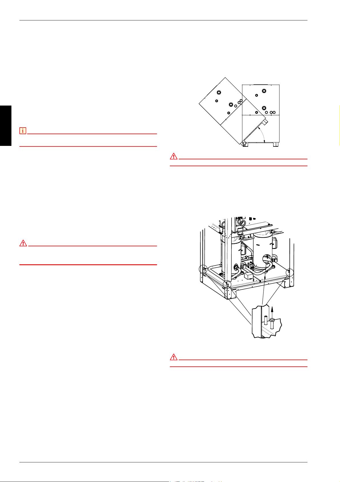
5 Transport
A lift truck is suited for transporting the unit on a level surface.
Carrying straps may be used if the heat pump needs to be trans-
ported on an uneven surface or carried up or down stairs. These
straps can be passed directly underneath the pallet.
ATTENTION!
The heat pump must not be tilted more than 45° (in any direction).
Use the holes provided in the sides of the frame to lift the unit
without the pallet. The side panel assemblies must be removed
for this purpose. Any commercially available length of pipe can
be used as a carrying aid.
After transportation, the transport fastening in the device is to be
removed from both sides of the base.
ATTENTION!
Before commissioning, the transport fastening must be removed.
All panelling can be removed to allow accessing the inside of the
device.
To remove the panelling, open the individual covers by unscrew-
ing the respective turn-lock fasteners and then gently tilting the
covers away from the device. Then lift them up out of the mount-
ings.
P
D
[
;
;
Loading ...
Loading ...
Loading ...