Loading ...
Loading ...
Loading ...
Instructions for the installer
22
NOTES
1 Requirement 3 does not apply to a freestanding or elevated cooking appliance which
is designed to prevent flames or the cooking vessels from extending beyond the
periphery of the appliance.
2 The ‘cooking surface area’ is defined as that part of the appliance
3 where cooking normally takes place and does not include those parts of the appliance
containing control knobs.
4 For definition of hob, see Clause 1.4.64.
5 For definition of trivet, see Clause 1.4.109.
6 Consideration is to be given to window treatments when located near cooking
appliances. See Clause 5.3.4.
6.4 Electrical connection
Make sure that the voltage and capacity of the power line conform to the data
shown on the plate located under the casing. Do not remove this plate for any
reason.
The plug at the end of the supply cable and the wall socket must be of the same
type and must conform to the applicable legislation on electrical installations.
Make sure that the supply line is suitably earthed.
Fit power line with an omnipolar circuit breaker with a contact opening gap equal
to or greater than 3 mm in an easily accessible position close to the hob.
Avoid the use of adapters and shunts.
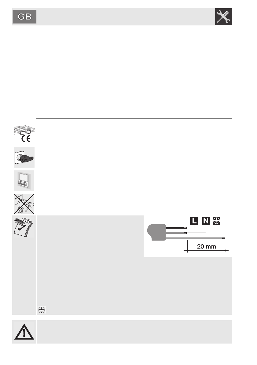
If the power cable is replaced, the cross-
section of wires in the new cable must be
no less than 0.75 mm2 (3 x 0.75 cable),
remembering that the end for connection to
the appliance must have a longer earth
wire (yellow/green)
, longer by at least 20 mm. Only use a H05V2V2-F or similar resistance cable to
the maximum temperature of 90°C. Its replacement must be carried out be a
specialised technician who must carry out the network connection following the
diagram below.
L = brown
N - blue
= yellow/green
The manufacturer cannot be held liable for damage to persons or things caused
by non-observance of the above directions or by interference with any part of the
appliance.
Loading ...
Loading ...
Loading ...