Loading ...
Loading ...
Loading ...
MRF-350 BASE STATION
Page 3
Optimizing Range and Reliability
1. Power on all AV components, lower all dimmers to 50% and power on
anything that may create RF Interference (particularly devices with high
speed microprocessors or hard drives).
2. Check that the address wheel on the bottom of the MRF-350 is set to
ID#0 (the interference “sniffing” position).
3. Connect the MRF-350 to its DC wall adapter and plug the wall adapter
into a live AC outlet. Place the MRF-350 in a convenient central loca-
tion in the equipment rack. Unlike an MRF-250, the MRF-350 can be
placed next to components with hard drives or high speed micro-
processors. There is no RF circuitry inside the MRF-350 itself.
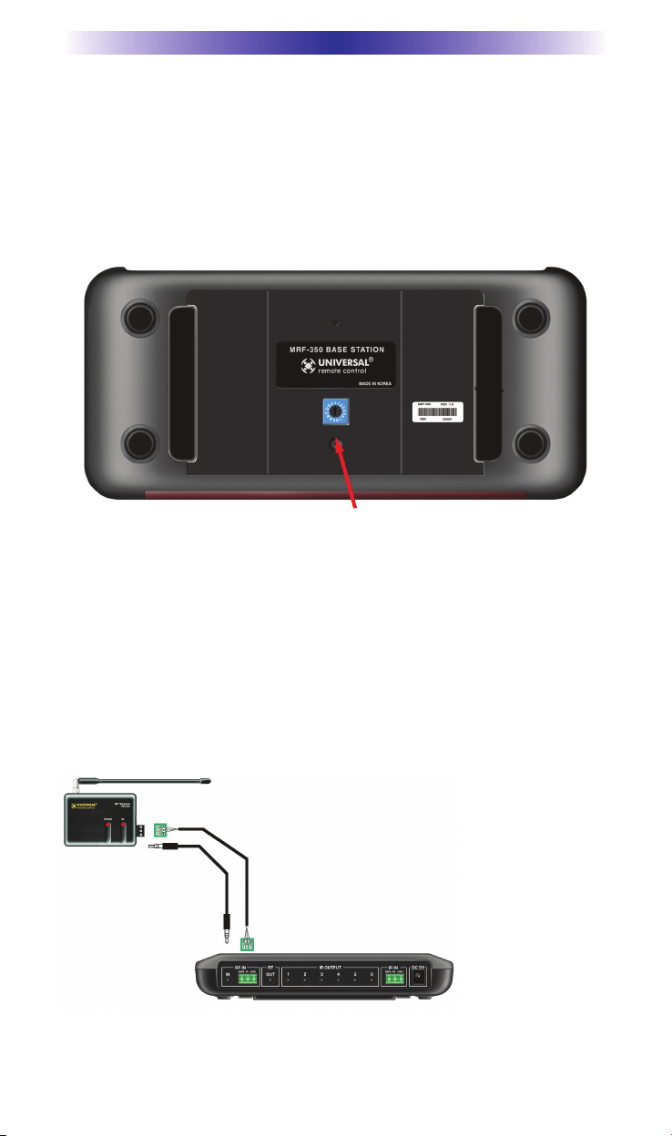
4. Connect the RFX-250 to the MRF-350’s RF INPUT. You can connect to
either the screw connector or the jack as shown:
Slide off the mounting plate to reveal the RF ID# rotary switch. Check that the arrow
pointer in the center of the wheel is pointed to 0, the default “interence sniffing” posi-
tion. If it is not, use a small flat blade screwdriver (included) to set the RF ID# to 0.
When connecting a single RFX-250 to the MRF-350
utilize the cable with 3.5 mm plugs on both ends.
When you need a longer wire or are connecting up
to three RFX-250s, use a cable with tinned ends.
Cable can be extended as much as 200’, then con-
nected to the removable screw connector plugs. If
you use CAT 5 connect four conductors to GND
(one from each twisted pair) and connect the remain-
ing conductors two at a time to 5V and DATA .
Loading ...
Loading ...
Loading ...