The information contained in this Manual is designed to assist you in the safe operation of the Nailer.
Some illustrations in this Manual may show details or attachments that differ from those on your own Nailer.
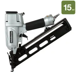
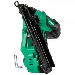
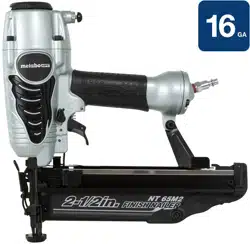
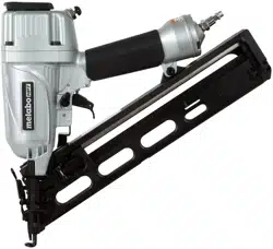
NAME OF PARTS
SPECIFICATIONS
Operating pressure
70 – 120 psi (4.9 – 8.3 bar 5 – 8.5 kgf/cm2)
Dimensions
Length × Height × Width
13-1/2” × 12” × 3-1/4”
(344 mm × 304 mm × 82 mm)
Weight
4.2 lbs. (1.9 kg)
Nail capacity
100 Nails
Air consumption
.045 ft3/cycle at 100 psi
(1.29 ltr/cycle at 6.9 bar)
(1.29 ltr/cycle at 7 kgf/cm2)
NAIL SELECTION
Only nails shown in the Table below can be driven with this Nailer.
Dimensions of nails
ACCESSORIES
Standard accessories
Optional accessories ... sold separately
○Pneumatic Tool Lubricant
1 oz. (30 cc) oil feeder (Code No.877153)
4 oz. (120 cc) oil feeder (Code No.874042)
1 quart (1 ltr) can (Code No.876212)
NOTE
Accessories are subject to change without any obligation on the part of HITACHI.
APPLICATIONS
○Manufactured Housing, On-site and Mobile Home Construction.
○Cabinets, Furniture, and Woodworking.
BEFORE OPERATION
Read section titled “SAFETY” (pages 4 – 6).
Make sure of the followings before operation.
Working environment
WARNING
●No flammable gas, liquid or other flammable objects at worksite.
●Clear the area of children or unauthorized personnel.
Air supply
DANGER
●NEVER use oxygen or other bottled gases. Explosion may occur.
WARNING
●Never connect Nailer to pressure which potentially exceeds 200 psi (13.7 bar 14 kgf/cm2).
●Never use non relieving coupler on Nailer.
1. Power source
○Use only clean, dry, regulated compressed air as a power source for this Nailer.
○Air compressors used to supply compressed air to this Nailer must comply with the requirements of the latest version of ANSI Standard B 19.3 “Safety Standard For Compressors For Process Industries.”
○Moisture or oil in the air compressor may accelerate wear and corrosion in the Nailer.
Drain daily.
2. Filter-Regulator-Lubricator
○Use a regulator with a pressure range of 0 – 120 psi (0 – 8.3 bar 0 – 8.5 kgf/cm2).
○Filter-regulator-lubricator units supply an optimum condition for the Nailer and extend the Nailer life. These units should always be used.
Filter
The filter removes moisture and dirt mixed in compressed air. Drain daily unless fitted with an automatic drain.
Keep the filter clean by regular maintenance.
Regulator
The regulator controls the operating pressure for safe operation of the Nailer.
Inspect the regulator before operation to be sure it operates properly.
Lubricator
The lubricator supplies an oil mist to the Nailer.
Inspect the lubricator before operation to be sure the supply of lubricant is adequate. Use Hitachi pneumatic tool lubricant.
3. Air hose
Air hose must have a minimum working pressure rating of 150 psi (10.4 bar 10.6 kgf/cm2) or 150% of the maximum pressure produced in the system, whichever is higher.
4. Air consumption
Using the Air consumption table and the Air compressor size formula, find a correct compressor size.
Air consumption table
psi Operating pressure (bar) (kgf/cm2)
80
(5.5)
(5.6)
90
(6.2)
(6.3)
100
(6.9)
(7)
Air ft3/cycle
.038
.042
.045
consumption (ltr/cycle)
(1.07)
(1.18)
(1.29)
Air compressor size formula Amount of air required
= number of Nailers
× average nails driven each minute per Nailer
× air consumption at given air pressure
× safety factor (always 1.2)
Example: 3 Nailers operating at 100 psi driving 30 nails per minute
Amount of air required
= 3 ´ 30 ´ .045 (1.29) ´ 1.2
= 4.9 CFM (ft3/min) (139 ltr/min)
After making the calculations as shown above, you should find a compressor providing 4.9 CFM of air that is required.
Lubrication
It is important that the Nailer be properly lubricated.
Without proper lubrication, the Nailer will not work properly and parts will wear prematurely.
○Use Hitachi pneumatic tool lubricant.
Do not use detergent oil or additives. These lubricants will harm the O-rings and other rubber parts. This will cause the Nailer to malfunction.
○Filter-regulator-lubricator units should always be used. Keep the lubricator filled with Hitachi pneumatic tool lubricant.
○If a lubricator is not available, supply 5 – 10 drops of Hitachi pneumatic tool lubricant into the air plug on the Nailer twice a day.
Cold weather care
○Do not store the Nailer in a cold weather environment. Keep the Nailer in a warm area until beginning the work.
○If the Nailer is already cold, bring it in a warm area and allow the Nailer to warm up before use.
1. Reduce the air pressure to 64 psi (4.4 bar 4.5 kgf/cm2).
2. Remove all nails from the Nailer.
3. Connect the air hose and free-fire (blank-fire) the Nailer.
The lowered air pressure will be enough to free-fire the Nailer.
Slow speed operation tends to warm up the moving part.
CAUTION
●Do not free-fire the Nailer at high pressure.
Testing the nailer
DANGER
●Operators and others in work area MUST wear safety glasses with side shields which conforms to ANSI Z87.1 specifications.
WARNING
●Never use Nailer unless push lever is operating properly.
Before actually beginning the nailing work, test the Nailer by using the check list below. Conduct the tests in the following order.
If abnormal operation occurs, stop using the Nailer and contact a Hitachi authorized service center immediately.
(1) Disconnect air hose from nailer. Remove all nails from nailer.
□ All crews must be tightened.
If any screws are loose, tighten them.
□ The push lever and trigger must move smoothly.
(2) Adjust the air pressure to 70 psi (4.9 bar 5 kgf/cm2).
Connect the air hose.
Do not load any nails in the Nailer.
Set the switching device to the upward position (SINGLE ACTUATION MECHANISM).
(Set the switching device to the upward position completely as shown in the diagram. Otherwise, it will not operate properly.)
□ The nailer must not leak air.
(3) Remove the finger from the trigger and press the push lever against the wood.
□ The nailer must not operate.
(4) Separate the push lever from the wood. Next, point the nailer downward, pull the trigger and then wait in that position for 5 seconds or longer.
□ The nailer must not operate.
(5) 1 Without touching the trigger, depress the push lever against the workpiece. Pull the trigger.
□ The nailer must operate.
2 Hold the trigger back while separating the push lever from the wood.
□ The nailer will remain in operated status (the driver blade will remain at the bottom).
3 Remove the finger from the trigger.
□ Nailer operation will end (the driver blade will return to the top).
(6) Set the switching device to the downward position (CONTACT ACTUATION MECHANISM).
(Set the switching device to the downward position completely as shown in the diagram. Otherwise, it will not operate properly.)
With the Nailer off the workpiece, pull the trigger.
Depress the push lever against the workpiece.
□ The nailer must operate.
(7) If no abnormal operation is observed, you may load nails in the Nailer.
Drive nails into the workpiece that is the same type to be used in the actual application.
□ The nailer must operate properly.
Adjusting air pressure
WARNING
●Do not exceed 120 psi (8.3 bar 8.5 kgf/cm2).
Adjust the air pressure at recommended operating pressure 70 – 120 psi (4.9 – 8.3 bar 5 – 8.5 kgf/cm2) according to the length of nails and the hardness of workpiece.
The correct air pressure is the lowest pressure which will do the job. Using the Nailer at a higher than required air pressure unnecessarily over stresses the Nailer.
Loading nails
WARNING
●When loading nails into the nailer, be sure to remove your finger from the trigger and disconnect the air hose from the nailer.
(1) Insert nail strip into rear of magazine.
(2) Slide the nail strip forward in the magazine. The nail strip should pass the nail stopper.
(3) Pull the nail feeder (B) back to engage the nail feeder (A) to the nail strip.
NOTE
○Use nail strip at least 5 nails remaining.
The Nailer is now ready to operate.
Removing the nails:
1. Depress the nail feeder (A) slightly and slowly slide the nail feeder (B) forward.
2. Remove the nails from the Nailer.
NAILER OPERATION
This Hitachi nailer is equipped with a nailer operation switching device.
Use SINGLE ACTUATION MECHANISM or CONTACT ACTUATION MECHANISM in accordance with the work to be performed.
Explanation of the various nailing operations
○SINGLE ACTUATION MECHANISM (SINGLE SEQUENTIAL ACTUATION MECHANISM): First, press the push lever against the wood; next, pull the trigger to drive the nail.
First, pull the trigger; next, press the push lever against the wood to drive the nail.
After nailing once, nailing will not be possible again until the trigger is released and pressed again.
○CONTACT ACTUATION MECHANISM: First, press the push lever against the wood; next, pull the trigger to drive the nail.
First, pull the trigger; next, press the push lever against the wood to drive the nail.
If the trigger is held back, a nail will be driven each time the push lever is pressed against the wood.
Methods of operation
This Nailer is equipped with the push lever and does not operate unless the push lever is depressed (upward position).
There are two methods of operation to drive nails with this Nailer.
They are
1. Intermittent operation (Trigger fire):
2. Continuous operation (Push lever fire):
(1) Intermittent operation (Trigger fire)
Use the SINGLE ACTUATION MECHANISM setting.
Set the switching device to the upward position (to set to SINGLE ACTUATION MECHANISM). (Set the switching device to the upward position completely as shown in the diagram. Otherwise, it will be set to CONTACT ACTUATION MECHANISM.)
Position the nail outlet on the workpiece with finger off the trigger.
Depress the push lever firmly until it is completely depressed.
Pull the trigger to drive a nail.
Remove finger from the trigger.
To continue nailing in a separate location, move the nailer along the wood, repeating steps 2 - 5 as required.
(2) Continuous operation (Push lever fire)
Using CONTACT ACTUATION MECHANISM
Set the switching device to the downward position (to set to CONTACT ACTUATION MECHANISM). (Set the switching device to the downward position completely as shown in the diagram. Otherwise, it will not operate properly.)
Pull the trigger with the Nailer off the workpiece.
Depress the push lever against the workpiece to drive a nail.
Move the Nailer along the workpiece with a bouncing motion. Each depression of the push lever will drive a nail.
As soon as the desired number of nails have been driven, remove finger from the trigger.
NOTE
●If all warnings and instructions are followed, safe operation is possible with all two systems: SINGLE ACTUATION MECHANISM and CONTACT ACTUATION MECHANISM.
●Always handle nails and package carefully. If nails are dropped, collating bond may be broken, which will cause mis-feeding and jamming.
●After nailing:
1) disconnect air hose from the Nailer;
2) remove all nails from the Nailer;
3) supply 5 – 10 drops of Hitachi pneumatic tool lubricant into the air plug on the Nailer; and
4) open the petcock on the air compressor tank to drain any moisture.
Adjusting the nailing depth
To assure that each nail penetrates to the same depth, be sure that:
1) the air pressure to the Nailer remains constant (requlator is installed and working properly), and
2) the Nailer is always held firmly against the workpiece.
If nails are driven too deep or shallow into the workpiece, adjust the nailing in the following order.
1. DISCONNECT AIR HOSE FROM NAILER.
2. If nails are driven too deep, turn the adjuster to the shallow side.
Adjustments are in half-turn increments.
If nails are driven too shallow, turn the adjuster to the deep side.
3. Stop turning the adjuster when a suitable position is reached for a nailing test.
4. Connect the air hose.
ALWAYS WEAR SAFETY GLASSES.
Perform a nailing test.
5. DISCONNECT AIR HOSE FROM NAILER.
6. Choose a suitable position for the adjuster.
Using the blow nozzle
This Nailer has a blow nozzle that blows out wood shavings which occur during work.
Press the knob with your thumb to use the blow nozzle, as shown in the figure.
NOTE
●When the blow nozzle is used for a long time, the nailing force may degrade temporarily. In this case, allows the air supply pressure to stabilize before starting work.
●Oil in the body or drained water from the compressor can sometimes spout out of the air outlet. It is recommended that you once conduct a test before use and see if such phenomenon happens at an environment where spouted oil will cause any inconvenience.
Changing the exhaust direction
The direction of the exhaust vent can be changed by turning the top cover.
Using the nose cap
If you like to protect the surface of workpiece against scratches or markings made by the push lever, attach the accessory nose cap to the push lever.
1. DISCONNECT AIR HOSE FROM NAILER.
2. Put the nose cap to the toe of the push lever.
3. The nose cap is marked to indicate the exit point of the nail, making alignment easier.
4. When not using the nose cap, secure in the storage compartment located on the reverse side of the magazine.
MAINTENANCE
NOTE
The information contained in this Manual is designed to assist you in the safe maintenance of the Nailer.
Some illustrations in this Manual may show details or attachments that differ from those on your own Nailer.
MAINTENANCE AND INSPECTION
Read section titled “SAFETY” (pages 4 – 6).
1. Clearing a jam.
Remove a jammed nail in the following order:
1. DISCONNECT AIR HOSE.
2. Remove all nails.
3. Release the lock lever and open guide plate (A).
4. Remove the jammed nail with a slotted- head screwdriver.
5. Close guide plate (A) and latch.
6. In case of frequent jam, contact a Hitachi authorized service center.
2. Inspecting the magazine.
1. DISCONNECT AIR HOSE.
2. Clean the magazine. Remove dust which may have accumulated in the magazine.
3. Lubricate the nail rail with Hitachi pneumatic tool lubricant.
3. Storing
○When not in use for an extended period, apply a thin coat of the lubricant to the steel parts to avoid rust.
○Do not store the Nailer in a cold weather environment. Keep the Nailer in a warm area.
○When not in use, the Nailer should be stored in a warm and dry place.
Keep out of reach children.
4. WARNING LABEL
Change the WARNING LABEL if missing or damaged.
A new WARNING LABEL is available from a Hitachi authorized service center.
5. Maintenance chart (See page 20)
6. Operator troubleshooting (See page 21)
7. Service parts list
CAUTION
Repair, modification and inspection of Hitachi Power Tools must be carried out by a Hitachi Authorized Service Center.
This Parts List will be helpful if presented with the tool to the Hitachi Authorized Service Center when requesting repair or other maintenance.
In the operation and maintenance of power tools, the safety regulations and standards prescribed in each country must be observed.
MODIFICATIONS
Hitachi Power Tools are constantly being improved and modified to incorporate the latest technological advancements.
Accordingly, some parts may be changed without prior notice.
SERVICE AND REPAIRS
All quality Nailers will eventually require servicing or replacement of parts because of wear from normal use.
NOTE
Specifications are subject to change without any obligation on the part of HITACHI.
Maintenance chart
ACTION
WHY
HOW
Drain air line filter daily.
Prevent accumulation of moisture and dirt.
Open manual petcock.
Keep lubricator filled.
Keep the Nailer lubricated.
Fill with Hitachi pneumatic tool lubricant.
Clean filter element — then blow air through filter in direction opposite to normal flow.
Prevent clogging of filter with dirt.
Follow manufacturer’s instructions.
Clean magazine and feeder mechanism.
Prevent a jam.
Blow clean daily.
Keep push lever working properly.
Promote operator safety and efficient Nailer operation.
Blow clean daily.
Lubricate the Nailer after nailing.
Extend the Nailer life.
Supply 5 – 10 drops of lubricant into the Nailer.
Drain air compressor.
Keep the Nailer operated properly.
Open petcock on air compressor tank.
Operator troubleshooting
Most minor problems can be resolved quickly and easily using the table below. If problems persist, contact a Hitachi authorized service center for assistance.
PROBLEM
CHECK METHOD
CORRECTION
Nailer operates, but no nail is driven.
Check for a jam.
Clear a jam page 18.
Nail feeder damaged?
Replace nail feeder.
Ribbon spring weakend or damaged?
Replace ribbon spring.
Check for proper nails.
Use only recommended nails.
Weak drive. Slow to cycle.
Check air pressure.
Increase air pressure.
(Do not exceed 120 psi (8.3
bar 8.5 kgf/cm2))
Check position of nailing depth adjustment adjuster.
Readjust per page 15.
———
Use Hitachi pneumatic tool lubricant.
Driver blade worn?
Contact Hitachi for replacement.
Piston O-ring worm or damaged?
Drives too deep.
Check air pressure.
Reduce air pressure. (Adjust 70 – 120 psi
(4.9 – 8.3 bar 5 – 8.5 kgf/cm2))
Check position of nailing
depth adjustment guide plate (A).
Readjust per page 15.
Skipping nails. Intermittent feed.
Check for proper nails.
Use only recommended nails.
———
Lubricate the nail rail per page 18.
Nail feeder damaged?
Replace nail feeder.
Ribbon spring weakend or damaged?
Replace ribbon spring.
Piston O-ring worn or damaged?
Contact Hitachi for replacement.
Nails jam.
Driven nail is bent.
Check for proper nails.
Use only recommended nails.
———
Lubricate the nail rail per page 18.
Driver blade worn?
Contact Hitachi for replacement.
Drives properly during normal operation, but does not drive fully at faster nailing speeds.


 ●
●
 ●
●