Loading ...
Loading ...
Loading ...
Attaching the optional ice
maker to a water supply
(cont.)
Connecting to refrigerator
NOTE: The first step for connecting
the water line to your refrigerator is
different depending on the type of
water valve provided with your refrig-
erator. See the diagrams at right to
determine the style of valve you have.
(On kit models, assemble water valve
to refrigerator per kit Instructions.)
1.
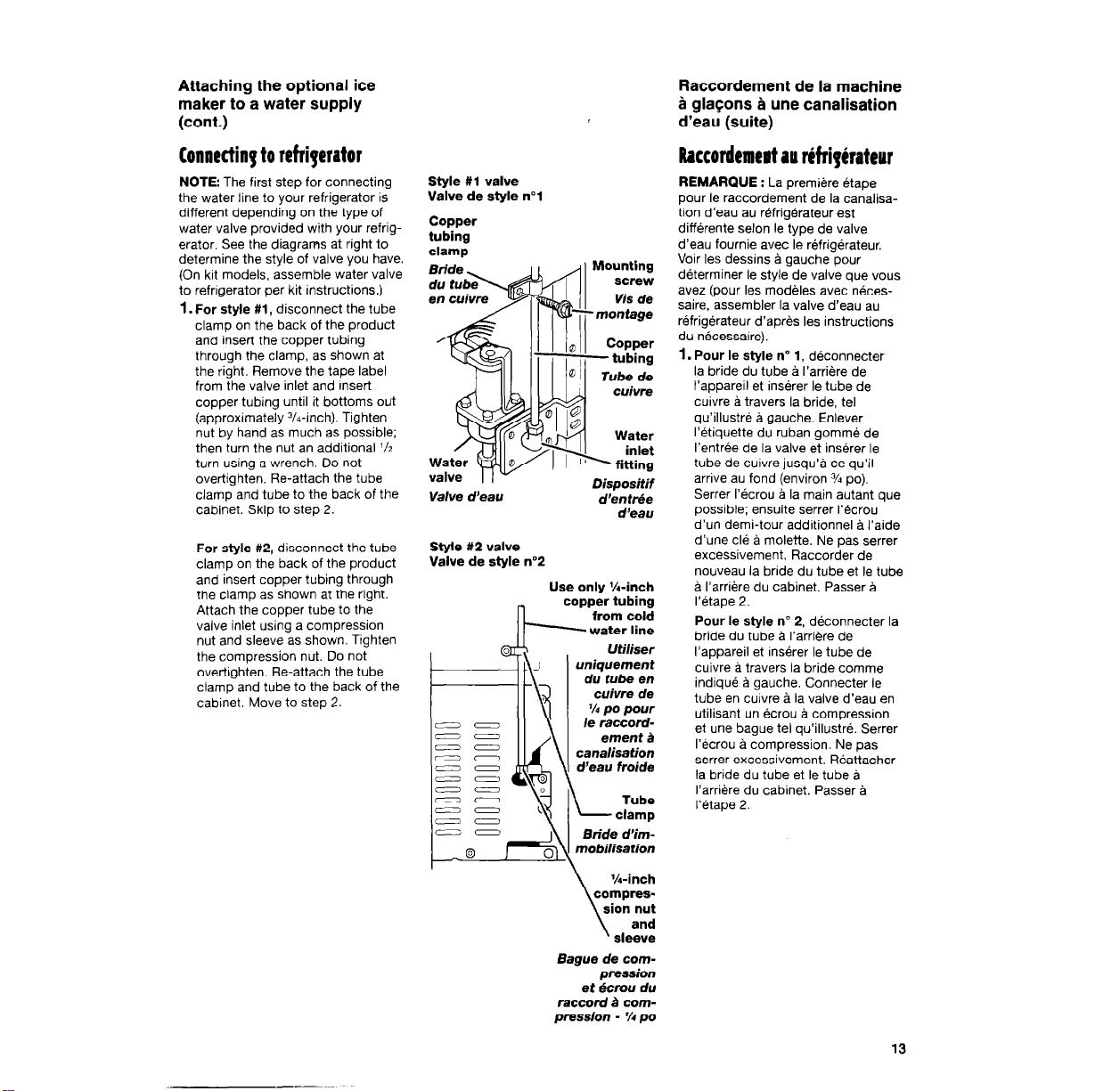
For style #l, disconnect the tube
clamp on the back of the product
and insert the copper tubing
through the clamp, as shown at
the right. Remove the tape label
from the valve inlet and Insert
copper tubing until it bottoms out
(approximately 3/4-inch). Tighten
nut by hand as much as possible;
then turn the nut an additional ‘12
turn using a wrench. Do not
overtighten. Re-attach the tube
clamp and tube to the back of the
cabinet. Skip to step 2.
For style #2, disconnect the tube
clamp on the back of the product
and insert copper tubing through
the clamp as shown at the right.
Attach the copper tube to the
valve inlet using a compression
nut and sleeve as shown. Tighten
the compression nut. Do not
overtighten. Re-attach the tube
clamp and tube to the back of the
cabinet. Move to step 2.
Style #l valve
Valve de style n”1
Copper
tubing
clamp
Valve d’eau
Dispositif
d’enttie
d’eau
Style #2 valve
Valve de style no2
Use only %-inch
copper tubing
from cold
-water line
Utiliser
uniquement
Bague de com-
pression
et Bcrou du
raccord B com-
pression - % po
Raccordement de la machine
5 gla$ons B une canalisation
d’eau (suite)
Raccordemert au riffipirateur
REMARQUE : La premiere &ape
pour le raccordement de la canalisa-
tion d’eau au rbfrigbrateur est
differente selon le type de valve
d’eau fournie avec le t+frig&ateur,
Voir les dessins I gauche pour
determiner le style de valve que vous
avez (pour les mod&les avec n&es-
saire. assembler la valve d’eau au
GfrigBrateur d’apres les instructions
du n&zessaire).
1. Pour le style no 1, dbconnecter
la bride du tube Q I’arrihre de
I’appareil et ins&er le tube de
cuivre L travers la bride, tel
qu’illustr8 b gauche. Enlever
I’Btiquette du ruban gomm6 de
I’entrke de la valve et ins&er le
tube de cuivre jusqu’g ce qu’il
arrive au fond (environ % PO).
Serrer 1’6crou & la main autant que
possible; ensuite serrer 1’8crou
d’un demi-tour additionnel g I’aide
d’une cl6 ti molette. Ne pas serrer
excessivement. Raccorder de
nouveau la bride du tube et le tube
B I’arrikre du cabinet. Passer B
1’6tape 2.
Pour le style nD 2, dbconnecter la
bride du tube g I’arri&e de
I’appareil et ins&er le tube de
cuivre ti travers la bride comme
indiqu6 g gauche. Connecter le
tube en cuivre B la valve d’eau en
utilisant un Bcrou 5 compression
et une bague tel qu’illustr6. Serrer
I’Bcrou g compression. Ne pas
serrer excessivement. Wattacher
la bride du tube et le tube ti
I’arri&re du cabinet. Passer a
1’6tape 2.
13
Loading ...
Loading ...
Loading ...