Loading ...
Loading ...
Loading ...
8 9
ASSEMBLY INSTRUCTIONS
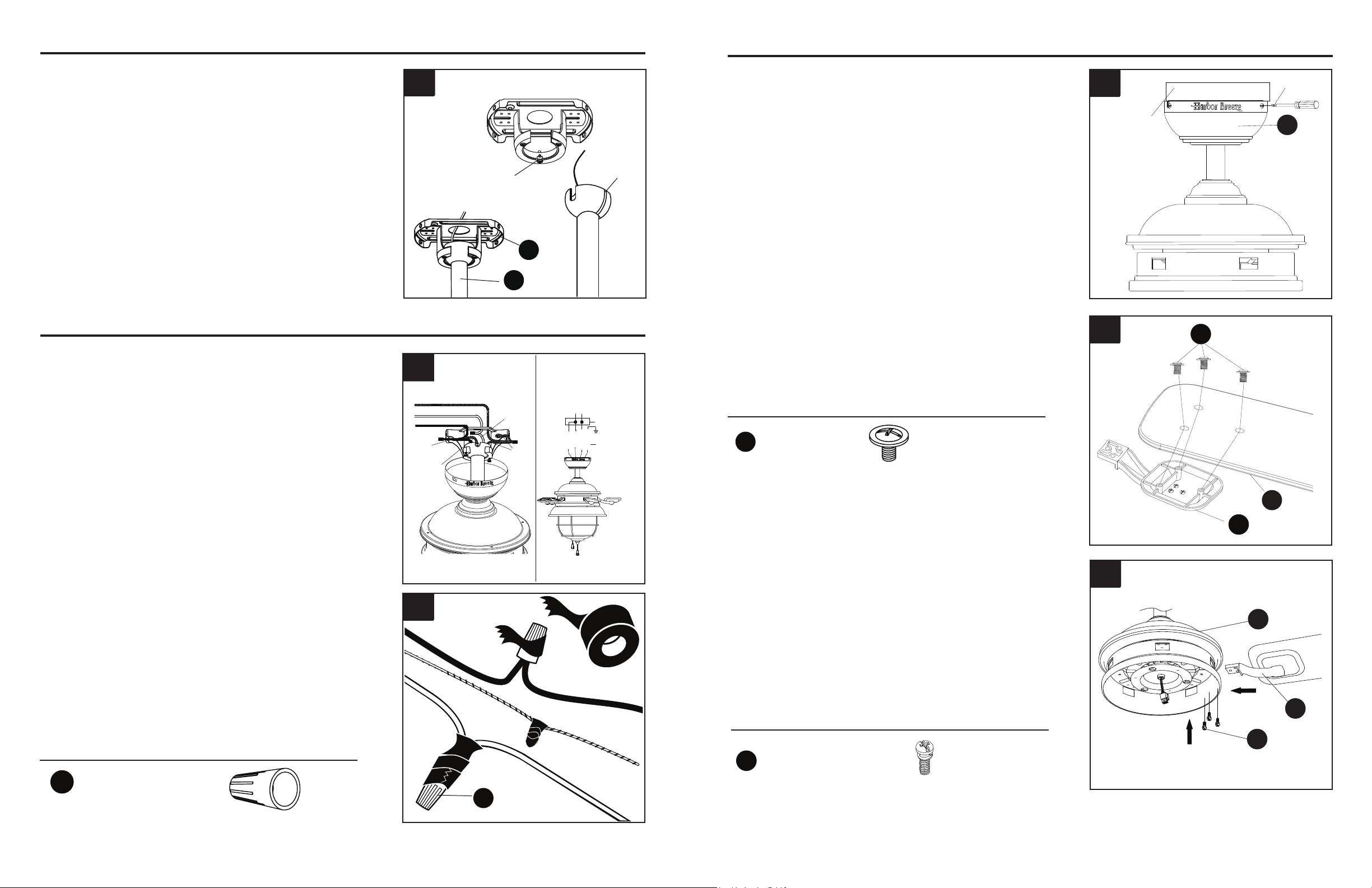
7. Install hanger ball on the top of downrod assembly
(E) into mounting bracket (A) opening. Rotate fan
until slot on hanger ball engages the tab on the
mounting bracket (A).
DANGER: Be careful when aligning the tab
to the slot! If not fully engaged, there is a
possibility of fan falling, which may result in
serious injury or death.
H
B
EE
7
Tab
Slot
A
E
WIRING
Hardware Used
1. Connect the BLACK and BLUE wires from the
fan to the house BLACK wire. Connect the
WHITE wire from fan to the house WHITE wire.
Connect all GROUNDED (GREEN) wires together
from fan to the house GREEN/GROUND wire.
Note: BLACK wire is hot power for fan. BLUE wire
is hot power for light kit. WHITE wire is common
for fan and light kit. GREEN wire is ground wire.
If house wires are different colors than referred
to above, stop immediately. Consult a licensed
electrician to determine proper wiring.
2. To connect wires, twist wire ends together and
screw wire with wire connectors (AA) in a clockwise
direction. Tape the wire connectors (AA) and wires
together with electrical tape (not included). Be sure
no bare wire or wire strands are visible after making
connection.
Place GREEN and WHITE connections on opposite
side of box from the BLACK and BLUE connections.
The splices should be turned upward and pushed
carefully up into the outlet box.
1
2
AA
FINAL INSTALLATION
1. Directly align the locking slots of the canopy (B) with
the two screws previously loosened (step 2, page 6)
in the mounting bracket (A). Push up to engage the
slots and turn clockwise to lock in place. Immediately
tighten the two screws rmly, then re-install the two
screws that were previously removed (step 2, page 6)
to fully secure the canopy (B) to the mounting bracket
(A).
2. Attach blade (G) to a blade arm (F) using three blade
screws (DD).
Repeat for remaining blade assemblies.
Hardware Used
DD
F
G
2
screw
outlet box
B
1
Ground/Green
White
Black
White
Black
Ground/
Green
Blue
Supply circuit
Ground/
Green
Outlet box
white
black
blue
black
white
green
3. Insert blade assembly through slot on fan motor
assembly (H) and align three screw holes in blade
arm (F) with screw holes in fan motor assembly (H).
Secure with three blade arm screws (EE). Repeat for
remaining blade assemblies.
3
Hardware Used
EE
Blade Arm Screw x 16
H
F
EE
x 4
Wire Connector
AA
DD
Blade Screw x 16
Page 8 Page 9
Loading ...
Loading ...
Loading ...