Download a free electronic copy of the Owner’s Manual
or Warranty Booklet by visiting the Owners tab at
www.ramtrucks.com (U.S.) or www.ramtruck.ca (Canada).
Download a free Vehicle Information App by visiting your
application store, Keyword (RAM Toolbox), or scanning the
Microsoft Tag. To put Microsoft Tags to work for you, use your
mobile phone’s browser or App store to download a Microsoft
Tag reader, like the free one at www.gettag.mobi. Then follow
the directions to scan the code.
Canada Only
iPhone
13D241-926-AA
RAM Trucks 1500/2500/3500
Tenth Edition
User Guide
Canada Only
Android
Getthe free mobile appfor your phone
http://gettag.mobi
U.S. Only

If you are the rst registered retail owner of your vehicle, you
may obtain a complimentary printed copy of the Owner’s Manual,
Navigation/Uconnect
®
Manuals or Warranty Booklet by calling
1-866-726-4636 (U.S.) or 1-800-387-1143 (Canada)
or by contacting your dealer.
This User Guide is intended to familiarize you with the important features
of your vehicle. The DVD enclosed contains your Owner’s Manual, Navigation/
Uconnect
®
Manuals, Warranty Booklets, Tire Warranty and Roadside
Assistance (new vehicles purchased in the U.S.) or Roadside Assistance
(new vehicles purchased in Canada) in electronic format. We hope you
nd it useful. Replacement DVD kits may be purchased by visiting
www.techauthority.com. Copyright 2016 FCA US LLC.
IMPORTANT
The driver’s primary responsibility is the safe operation of the vehicle. Driving while
distracted can result in loss of vehicle control, resulting in a collision and personal
injury. FCA US LLC strongly recommends that the driver use extreme caution when
using any device or feature that may take their attention off the road. Use of any
electrical devices such as cell phones, computers, portable radios, vehicle navigation
or other devices by the driver while the vehicle is moving is dangerous and could lead
to a serious collision. Texting while driving is also dangerous and should never be
done while the vehicle is moving. If you find yourself unable to devote your full
attention to vehicle operation, pull off the road to a safe location and stop your
vehicle. Some States or Provinces prohibit the use of cellular telephones or texting
while driving. It is always the driver’s responsibility to comply with all local laws.
DRIVING AND ALCOHOL
Drunken driving is one of the most frequent causes of collisions. Your driving
ability can be seriously impaired with blood alcohol levels far below the legal
minimum. If you are drinking, don’t drive. Ride with a designated non-drinking
driver, call a cab, a friend, or use public transportation.
WARNING
Driving after drinking can lead to a collision. Your perceptions are less sharp,
your reflexes are slower, and your judgment is impaired when you have been
drinking. Never drink and then drive.
This guide has been prepared to help you get quickly acquainted with
your new RAM and to provide a convenient reference source for common
questions. However, it is not a substitute for your Owner’s Manual.
For complete operational instructions, maintenance procedures and
important safety messages, please consult your Owner’s Manual,
Navigation/Uconnect
®
Manuals and other Warning Labels in your vehicle.
Not all features shown in this guide may apply to your vehicle. For
additional information on accessories to help personalize your vehicle, visit
www.mopar.com (U.S.), www.mopar.ca (Canada) or your local RAM dealer.

INTRODUCTION/WELCOME
WELCOME FROM FCA US LLC ......3
CONTROLS AT A GLANCE
DRIVER COCKPIT ..............6
INSTRUMENT CLUSTER ..........8
GETTING STARTED
KEYFOB ...................10
KEYLESS ENTER-N-GO™ .........11
REMOTE START ..............12
THEFT ALARM ...............13
SEATBELT ..................13
SUPPLEMENTAL RESTRAINT SYSTEM
(SRS) — AIR BAGS .............14
CHILD RESTRAINTS ............15
FRONT SEATS ................20
HEATED/VENTILATED SEATS .......22
HEATED STEERING WHEEL ........23
TILT STEERING COLUMN .........24
OPERATING YOUR VEHICLE
ENGINE BREAK-IN
RECOMMENDATIONS ...........25
TURN SIGNALS/WIPER/WASHER/HIGH
BEAMS LEVER ................ 26
HEADLIGHT SWITCH ............27
SPEED CONTROL ..............28
EIGHT–SPEED AUTOMATIC TRANSMISSION
— IF EQUIPPED ...............29
ELECTRONIC RANGE SELECT (ERS)
OPERATION .................30
AIR SUSPENSION SYSTEM ........32
MANUAL CLIMATE CONTROLS WITHOUT
TOUCH-SCREEN ...............34
MANUAL CLIMATE CONTROLS WITH
TOUCH-SCREEN ...............35
AUTOMATIC CLIMATE CONTROLS WITH
TOUCH-SCREEN ...............36
PARKSENSE
®
REAR PARK ASSIST . . . 37
PARKVIEW
®
REAR BACK-UP CAMERA
...38
TIRE PRESSURE MONITOR SYSTEM
(TPMS) – 2500 MODELS ONLY ......38
POWER SLIDING REAR WINDOW ....39
POWER SUNROOF .............40
WIND BUFFETING .............41
ELECTRONICS
YOUR VEHICLE'S SOUND SYSTEM . . . 42
IDENTIFYING YOUR RADIO ........44
Uconnect
®
Access (AVAILABLE ON
Uconnect
®
8.4A AND Uconnect
®
8.4AN) (IF
EQUIPPED) ..................45
Uconnect
®
3.0 ................55
Uconnect
®
5.0 ................57
Uconnect
®
8.4A ............... 64
Uconnect
®
8.4AN ..............82
STEERING WHEEL AUDIO CONTROLS . . 102
ELECTRONIC VEHICLE INFORMATION
CENTER (EVIC) .............. 102
PROGRAMMABLE FEATURES ......103
UNIVERSAL GARAGE DOOR OPENER
(HomeLink
®
) ................105
POWER INVERTER ............ 108
POWER OUTLETS ............109
OFF-ROAD CAPABILITIES
FOUR WHEEL DRIVE OPERATION . . . 110
UTILITY
TONNEAU COVER .............113
EASY-OFF TAILGATE ...........113
PICKUP BOX ................114
RAMBOX
®
..................115
TOWING & PAYLOAD ...........119
TOW/HAUL MODE ............121
INTEGRATED TRAILER BRAKE
MODULE ..................121
RECREATIONAL TOWING (BEHIND
MOTORHOME, ETC.) ...........122
DIESEL
DIESEL ENGINE BREAK-IN
RECOMMENDATIONS ...........125
DIESEL ENGINE STARTING
PROCEDURES ...............126
DIESEL EXHAUST BRAKE (ENGINE
BRAKING) .................127
IDLE-UP FEATURE (AUTOMATIC
TRANSMISSION ONLY) .........128
ENGINE MOUNTED FUEL FILTER/WATER
SEPARATOR ................129
UNDERBODY MOUNTED FUEL
FILTER/WATER SEPARATOR .......130
ADDING FUEL – DIESEL ENGINE
ONLY ..................... 131
EXHAUST REGENERATION .......131
COOL-DOWN IDLE CHART ........ 133
DIESEL EXHAUST FLUID ........133
WHAT TO DO IN EMERGENCIES
ROADSIDE ASSISTANCE .........136
INSTRUMENT CLUSTER WARNING
LIGHTS ................... 136
IF YOUR ENGINE OVERHEATS .....140
JACKING AND TIRE CHANGING ....141
JUMP-STARTING .............155
EMERGENCY TOW HOOKS .......157
SHIFT LEVER OVERRIDE ........158
TOWING A DISABLED VEHICLE ....161
FREEING A STUCK VEHICLE ......162
EVENT DATA RECORDER (EDR) .... 163
TABLE OF CONTENTS

MAINTAINING YOUR VEHICLE
OPENING THE HOOD ..........164
ENGINE COMPARTMENT ........165
FLUIDS AND CAPACITIES ........ 170
MAINTENANCE SCHEDULE – GASOLINE
ENGINE ...................175
MAINTENANCE SCHEDULE —
6.7L CUMMINS DIESEL ENGINE . . . 180
FUSES ....................187
TIRE PRESSURES .............191
WHEEL AND WHEEL TRIM CARE . . . 191
EXTERIOR BULBS ............193
CUSTOMER ASSISTANCE
FCA US LLC CUSTOMER CENTER . . . 194
FCA CANADA INC. CUSTOMER
CENTER ..................194
ASSISTANCE FOR THE HEARING
IMPAIRED .................194
PUBLICATIONS ORDERING ....... 195
REPORTING SAFETY DEFECTS IN THE
UNITEDSTATES .............. 195
MOPAR ACCESSORIES
AUTHENTIC ACCESSORIES BY
MOPAR
®
..................196
FAQ (How To?)
FREQUENTLY ASKED QUESTIONS . . . 197
INDEX
....................199
TABLE OF CONTENTS
2

WELCOME FROM FCA US LLC
Congratulations on selecting your new FCA US LLC vehicle. Be assured that it
represents precision workmanship, distinctive styling, and high quality - all essen-
tials that are traditional to our vehicles.
Your new FCA US LLC vehicle has characteristics to enhance the driver's control
under some driving conditions. These are to assist the driver and are never a
substitute for attentive driving. They can never take the driver's place. Always drive
carefully.
Your new vehicle has many features for the comfort and convenience of you and your
passengers. Some of these should not be used when driving because they take your
eyes from the road or your attention from driving. Never text while driving or take your
eyes more than momentarily off the road.
This guide illustrates and describes the operation of features and equipment that are
either standard or optional on this vehicle. This guide may also include a description
of features and equipment that are no longer available or were not ordered on this
vehicle. Please disregard any features and equipment described in this guide that are
not available on this vehicle. FCA US LLC reserves the right to make changes in
design and specifications and/or make additions to or improvements to its products
without imposing any obligation upon itself to install them on products previously
manufactured.
This User Guide has been prepared to help you quickly become acquainted with the
important features of your vehicle. It contains most things you will need to operate
and maintain the vehicle, including emergency information.
The DVD includes a computer application containing detailed owner's information
which can be viewed on a personal computer or MAC computer. The multimedia DVD
also includes videos which can be played on any standard DVD player (including the
Uconnect
®
Touchscreen Radios if equipped with DVD player capabilities). Additional
DVD operational information is located on the back of the DVD sleeve.
For complete owner information, refer to your Owner's Manual on the DVD in the owner’s
kit provided at the time of new vehicle purchase. For your convenience, the information
contained on the DVD may also be printed and saved for future reference.
FCA US LLC is committed to protecting our environment and natural resources. By
converting from paper to electronic delivery for the majority of the user information
for your vehicle, together we greatly reduce the demand for tree-based products and
lessen the stress on our environment.
VEHICLES SOLD IN CANADA
With respect to any vehicles sold in Canada, the name FCA US LLC shall be deemed
to be deleted and the name FCA Canada Inc. used in substitution (excluding legal
lines).
INTRODUCTION/WELCOME
3

WARNING!
• Pedals that cannot move freely can cause loss of vehicle control and increase
the risk of serious personal injury.
• Always make sure that objects cannot fall into the driver foot well while the
vehicle is moving. Objects can become trapped under the brake pedal and
accelerator pedal causing a loss of vehicle control.
• Failure to properly follow floor mat installation or mounting can cause interfer-
ence with the brake pedal and accelerator pedal operation causing loss of
control of the vehicle.
• Never leave children alone in a vehicle, or with access to an unlocked vehicle.
Allowing children to be in a vehicle unattended is dangerous for a number of
reasons. A child or others could be seriously or fatally injured. Children should
be warned not to touch the parking brake, brake pedal or the transmission gear
selector.
• Do not leave the Key Fob in or near the vehicle, or in a location accessible to
children, and do not leave the ignition of a vehicle equipped with Keyless
Enter-N-Go in the ACC or ON/RUN mode. A child could operate power windows,
other controls, or move the vehicle.
• Never use the “PARK” position as a substitute for the parking brake. Always
apply the parking brake fully when parked to guard against vehicle movement
and possible injury or damage.
• Refer to your Owner's Manual on the DVD for further details.
INTRODUCTION/WELCOME
4

USE OF AFTERMARKET PRODUCTS (ELECTRONICS)
The use of aftermarket devices including cell phones, MP3 players, GPS systems, or
chargers may affect the performance of on-board wireless features including Keyless
Enter-N-Go™ and Remote Start range. If you are experiencing difficulties with any of
your wireless features, try disconnecting your aftermarket devices to see if the
situation improves. If your symptoms persist, please see an authorized dealer.
CHRYSLER, DODGE, JEEP, RAM, MOPAR and Uconnect are registered trademarks
of FCA US LLC.
COPYRIGHT ©2016 FCA US LLC
INTRODUCTION/WELCOME
5

DRIVER COCKPIT
CONTROLS AT A GLANCE
6

A. Headlight Switch pg. 27
B. Turn Signal/Wiper/Washer/High
Beams Lever pg. 26
C. Electronic Vehicle Information Center
(EVIC) Controls pg. 102
D. Electronic Vehicle Information Center
(EVIC) Display pg. 9
E. Instrument Cluster pg. 8
F. Four Wheel Drive Operation pg. 110
G. Identify Your Audio System pg. 42
H. Audio System Hard Controls pg. 42
I. Power Inverter Outlet pg. 108
J. Manual Climate Controls pg. 34
K. Switch Panel
• Diesel Exhaust Brake
• Tow/Haul pg. 121
• Electronic Stability Control pg. 136
• Air Suspension System
• ParkSense
®
Rear Park Assist pg. 37
• Tire Pressure Monitoring System
(TPMS) pg. 136
• Front Heated Seats pg. 22
• Front Ventilated Seats pg. 22
• Heated Steering Wheel pg. 23
• Integrated Trailer Brake Module
pg. 121
• Engine Stop Start
L. Shifter
M. Keyless Engine Starting/Stopping
pg. 12
N. Electronic Speed Control pg. 28
O. Hood Release (below steering wheel
at base of instrument panel) pg. 164
P. Parking Brake Release
Q. Power Mirrors
R. Power Windows
S. Power Door Locks
CONTROLS AT A GLANCE
7

INSTRUMENT CLUSTER
Warning Lights
- Low Fuel Warning Light
- Charging System Light**
- Oil Pressure Warning Light**
- Anti-Lock Brake (ABS) Light**
- Air Bag Warning Light**
- Electronic Throttle Control (ETC) Light
- Engine Temperature Warning Light
- Transmission Temperature Warning Light
- Seat Belt Reminder Light
BRAKE
- Brake Warning Light**
- Malfunction Indicator Light (MIL)**
- SERV (Service) 4WD Indicator Light
- Low Coolant Level Indicator Light
(See page 136 for more information.)
CONTROLS AT A GLANCE
8

Indicators
6
- Turn Signal Indicators
- High Beam Indicator
- Park/Headlight ON
Indicator*
- Front Fog Light Indicator
-
Vehicle Security Indicator*
- TOW/HAUL Indicator*
- Four-Wheel Drive LOW
Mode Indicator
- Four-Wheel Drive and
4LOCK Mode Indicator
- 4WD Auto Indicator
- Electronic Stability Con-
trol (ESC) Indicator
Light*
- Electronic Stability Con-
trol (ESC) Off Indicator
- Cargo Lamp On Indicator
- Door Ajar Indicator
- Electronic Speed Control
Set Indicator
- Check Fuel Filler
* If equipped
** Bulb Check with Key On
EVIC Messages
NOTE:
Refer to Electronic Vehicle Information Center (EVIC) in this guide or your owners
manual for additional information.
CONTROLS AT A GLANCE
9

KEY FOB
Locking And Unlocking The Doors
• Press and release the UNLOCK button
on the RKE transmitter once to unlock
the driver’s door (EVIC can be setup
for driver door first, otherwise this will
unlock all doors), or press the unlock
button twice within five seconds to
unlock all doors, the tailgate and the
RamBox
®
(if equipped). The turn sig-
nal lights will flash to acknowledge the
unlock signal. The illuminated entry
system will also turn on.
• All doors can be programmed to un-
lock on the first press of the UNLOCK
button. Refer to Programmable Fea-
tures in this guide.
Panic Alarm
• Press the PANIC button once to turn the panic alarm on.
• Wait approximately three seconds and press the button a second time to turn the
panic alarm off.
Emergency Key
• Should the battery in the vehicle or the Key Fob transmitter go dead, there is an
emergency key located in the Key Fob that can be used for locking and unlocking
the doors. To remove the emergency key, slide the button at the top of the Key Fob
sideways with your thumb and then pull the key out with your other hand.
WARNING!
• Never leave children alone in a vehicle, or with access to an unlocked vehicle.
Allowing children to be in a vehicle unattended is dangerous for a number of
reasons. A child or others could be severely injured or killed. Children should be
warned not to touch the parking brake, brake pedal, or the shift lever. Do not
leave the Key Fob in or near the vehicle, or in a location accessible to children,
and do not leave a vehicle equipped with Keyless Enter-N-G0™ in the ACC or
ON/RUN mode. A child could start the vehicle, operate power windows, other
controls, or move the vehicle.
• Do not leave children or animals inside parked vehicles in hot weather. Interior
heat build-up may cause them to be severely injured or killed.
GETTING STARTED
10

KEYLESS ENTER-N-GO™
• The Keyless Enter-N-Go™ system is an enhancement to the vehicle's Key Fob.
This feature allows you to lock and unlock the vehicle's door(s) without having to
press the Key Fob lock or unlock buttons, as well as starting and stopping the
vehicle with the press of a button.
To Unlock From The Driver or Passenger Side:
• With a valid Keyless Enter-N-Go™ Key
Fob located outside the vehicle and
within 5 ft (1.5m) of the driver or
passenger side door handle, grab ei-
ther front door handle to unlock the
door automatically.
To Lock The Vehicle’s Doors
• With a valid Keyless Enter-N-Go™ Key
Fob transmitter within 5 ft (1.5 m) of
the driver or passenger front door
handles, press the door handle LOCK
button to lock all doors.
• DO NOT grab the door handle, when pressing the door handle lock button. This
could unlock the door(s).
NOTE:
• After pressing the door handle LOCK button, you must wait two seconds before
you can lock or unlock the doors, using either Passive Entry door handle. This is
done to allow you to check if the vehicle is locked by pulling the door handle,
without the vehicle reacting and unlocking.
• The Passive Entry system will not operate if the RKE transmitter battery is dead.
The vehicle doors can also be locked by using the RKE transmitter lock button or the
lock button located on the vehicles interior door panel.
GETTING STARTED
11

Engine Starting/Stopping
Starting
• With a valid Keyless Enter-N-Go™ Key
Fob inside the vehicle.
• Place the shift lever in PARK or NEU-
TRAL.
• While pressing the brake pedal, press
the ENGINE START/STOP button
once. If the engine fails to start, the
starter will disengage automatically
after 10 seconds.
• To stop the cranking of the engine
prior to the engine starting, press the button again.
NOTE:
In case the ignition switch does not change with the push of a button, the RKE
transmitter (Key Fob) may have a low or dead battery. In this situation a back up
method can be used to operate the ignition switch. Put the nose side of the Key Fob
(side opposite of the Emergency Key) against the ENGINE START/STOP button and
push to operate the ignition switch.
Stopping
• Bring the vehicle to a complete stop.
• Place the shift lever in the PARK position.
• Press the ENGINE START/STOP button once. The ignition switch will return to the
OFF position.
NOTE:
If the shift lever is not in PARK and the vehicle is in motion, the ENGINE START/STOP button
must be held for two seconds with the vehicle speed above 5 mph (8 km/h) before the
engine will shut off.
REMOTE START
• Press the REMOTE START button on the Key Fob twice within five seconds.
Pressing the REMOTE START
button a third time shuts the engine off.
• To drive the vehicle, press the UNLOCK button, insert the Key Fob in the ignition
and turn to the ON/RUN position.
• With remote start, the engine will only run for 15 minutes (timeout) unless the
ignition Key Fob is placed in the ON/RUN position.
• The vehicle must be started with the Key Fob after two consecutive timeouts.
GETTING STARTED
12

WARNING!
• Do not start or run an engine in a closed garage or confined area. Exhaust gas
contains Carbon Monoxide (CO) which is odorless and colorless. Carbon Mon-
oxide is poisonous and can cause you or others to be severely injured or killed
when inhaled.
• Keep Key Fob transmitters away from children. Operation of the Remote Start
System, windows, door locks or other controls could cause you and others to be
severely injured or killed.
THEFT ALARM
To Arm:
• Press the Key Fob LOCK button or the power door lock switch while the door is
open.
To Disarm:
• Press the Key Fob UNLOCK button or turn the ignition to the ON/RUN position.
SEAT BELT
• Be sure everyone in your vehicle is in a seat and using a seat belt properly.
• Position the lap belt across your thighs, below your abdomen. To remove slack in
the lap portion, pull up a bit on the shoulder belt. To loosen the lap belt if it is too
tight, tilt the latch plate and pull on the lap belt. A snug belt reduces the risk of
sliding under the belt in a collision.
• Position the shoulder belt on your chest so that it is comfortable and not resting
on your neck. The retractor will withdraw any slack in the belt.
• A shoulder belt placed behind you will not protect you from injury during a
collision. You are more likely to hit your head in a collision if you do not wear your
shoulder belt. The lap and shoulder belt are meant to be used together.
• A belt that is too loose will not protect you properly. In a sudden stop you could
move too far forward, increasing the possibility of injury. Wear your seat belt
snugly.
• A frayed or torn belt could rip apart in a collision and leave you with no protection.
Inspect the belt system periodically, checking for cuts, frays, or loose parts.
Damaged parts must be replaced immediately. Do not disassemble or modify the
system. Seat belt assemblies must be replaced after a collision if they have been
damaged (bent retractor, torn webbing, etc.).
• The seat belts for both front seating positions are equipped with pretensioning
devices that are designed to remove slack from the seat belt in the event of a
collision.
• A deployed pretensioner or a deployed air bag must be replaced immediately.
GETTING STARTED
13

WARNING!
In a collision, you and your passengers can suffer much greater injuries if you are
not buckled up properly. You can strike the interior of your vehicle or other
passengers, or you can be thrown out of the vehicle. Always be sure you and others
in your vehicle are buckled up properly.
SUPPLEMENTAL RESTRAINT SYSTEM (SRS) — AIR BAGS
• This vehicle has Advanced Front Air Bags for both the driver and right front
passenger as a supplement to the seat belt restraint system. The Advanced Front
Air Bags will not deploy in every type of collision.
• Advanced Front Air Bags are designed to provide additional protection by
supplementing the seat belts in certain frontal collisions depending on several
factors, including the severity and type of collision. Advanced Front Air Bags are
not expected to reduce the risk of injury in rear, side, or rollover collisions.
• This vehicle is equipped with Supplemental Side Air Bag Inflatable Curtains to
protect the driver, front and rear passengers sitting next to a window.
• This vehicle is equipped with Supplemental Seat-Mounted Side Air Bags to
provide enhanced protection to help protect an occupant during a side impact.
•
If the Air Bag Warning Light is not on during starting, stays on, or turns on while
driving, have the vehicle serviced by an authorized service center immediately.
• Refer to the Owner's Manual on the DVD for further details regarding the
Supplemental Restraint System (SRS).
WARNING!
•
Relying on the air bags alone could lead to more severe injuries in a collision. The air
bags work with your seat belt to restrain you properly. In some collisions, the air bags
won't deploy at all. Always wear your seat belts even though you have air bags.
• Being too close to the steering wheel or instrument panel during Advanced Front
Air Bag deployment could cause serious injury, including death. Air bags need
room to inflate. Sit back, comfortably extending your arms to reach the steering
wheel or instrument panel.
• Supplemental Side Air Bag Inflatable Curtains and Supplemental Seat-
Mounted Side Air Bags need room to inflate. Do not lean against the door or
window. Sit upright in the center of the seat.
• Being too close to the Supplemental Side Air Bag Inflatable Curtain and/or
Seat-Mounted Side Air Bag during deployment could cause you to be severely
injured or killed.
• Do not drive your vehicle after the air bags have deployed. If you are involved in
another collision, the air bags will not be in place to protect you.
• After any collision, the vehicle should be taken to an authorized dealer
immediately.
GETTING STARTED
14

CHILD RESTRAINTS
• Children 12 years and under should ride properly buckled up in a rear seat, if
available. According to crash statistics, children are safer when properly re-
strained in the rear seats rather than in the front.
• Every state in the United States and all Canadian provinces require that small
children ride in proper restraint systems. This is the law, and you can be
prosecuted for ignoring it.
NOTE:
• For additional information, refer to www.seatcheck.org or call
1–866–SEAT-CHECK (1–866–732–8243).
• Canadian residents, should refer to Transport Canada’s website for additional
informationhttp://www.tc.gc.ca/eng/roadsafety/
safedrivers-childsafety-index-53.htm.
Installing The LATCH - Compatible Child Restraint System
• Your vehicle’s second row passenger seats are equipped with the child restraint
anchorage system called LATCH, which stands for Lower Anchors and Tether for
CHildren. LATCH child restraint anchorage systems are installed in the rear seat
outboard positions.
• LATCH equipped seating positions have both lower anchor bars, located at the
back of the seat cushion, and tether strap anchorages, located behind the seat
back.
Installing The Lower Attachments:
• The vehicle lower anchorages are round bars located at the rear of the seat cushion
where it meets the seatback. The rear seat lower anchors can be readily identified
by the symbol
located on the seatback directly above the anchorages and are
just visible when you lean into the rear seat to install the child restraint.
• Loosen the child seat adjusters on the
lower straps and on the tether strap so
that you can attach the hooks or con-
nectors to the vehicle anchors more
easily.
• Attach the lower hooks or connectors
over the top of the seatcover material.
• Then tighten the straps as you push
the child restraint rearward and down-
ward into the seat.
GETTING STARTED
15

Tether Anchorage Points At The Right And Center Front Seat (Regular Cab - All
Seats):
• Place the child restraint on the seat and adjust the tether strap so that it will reach
over the seat back under the head restraint to the tether anchor directly behind the
seat.
• Lift the cover (if equipped), and attach
the hook to the square opening in the
sheet metal.
• Install the child restraint and remove
the slack in the tether strap according
to the manufacturer's instructions.
Child Restraint Installation Sequence
(Mega Cab® - Rear Seats):
• Place a child restraint on each out-
board rear seat and adjust the tether
strap so that it will reach under the
head restraint to the tether anchor directly behind the seat.
• Lift the cover, and attach the hook to the square opening in the sheet metal.
• Install the child restraint and remove the slack in the tether strap according to the
manufacturer's instructions.
Child Restraints Installation Sequence (Quad Cab®/Crew Cab - Rear Seats)
The top tether anchorages in this vehicle are tether strap loops located between the
rear glass and the back of the rear seat. There is a tether strap loop located behind
each seating position. Follow the steps below to attach the tether strap of the child
restraint.
Right or Left Outboard Seats:
1. Raise the head restraint and reach between the rear seat and rear glass to access
the tether strap loop.
Head Restraint In Raised Position Tether Strap Loop With Center Head Re-
straint In Raised Position
GETTING STARTED
16

2. Place a child restraint on the seat and adjust the tether strap so that it will reach
over the seat back, under the head restraint, through the tether strap loop behind
the seat and over to the tether strap loop behind the center seat.
3. Pass the tether strap hook under the head restraint behind the child seat, through
the tether strap loop behind the seat and over to the center tether strap loop.
4. Attach the hook to the center tether
strap loop (see diagram). Tighten the
tether strap according to the child
seat manufacturer’s instructions.
NOTE:
If there are child seats in both of the
outboard (left and right) seating posi-
tions, the tether strap hooks of both child
seats should be connected to the center
tether strap loop. This is the correct way
to tether two outboard child seats.
Center Seat:
1. Raise the head restraint and reach between the rear seat and rear glass to access
the tether strap loop.
2. Place a child restraint on the seat and
adjust the tether strap so that it will
reach over the seat back, under the
head restraint, through the tether
strap loop behind the seat and over to
the tether strap loop behind either the
right or left outboard seat.
Tether Strap Through Outboard Tether Strap Loop
Tether Strap Through Outboard Tether Strap
Loop And Attached To Center Tether Strap Loop
Tether Strap Loop With Head Restraint In
Raised Position
GETTING STARTED
17

3. Pass the tether strap hook under the head restraint behind the child seat, through
the tether strap loop behind the seat and over to the right or left outboard tether
strap loop.
4. Attach the hook to the outboard tether
strap loop (see diagram). Tighten the
tether strap according to the child
seat manufacturer’s instructions.
Installing Three Child Restraints:
1. Place a child restraint on each out-
board rear seat. Route the tether
straps following the directions for
right and left seating positions, above.
2. Attach both hooks to the center tether
strap loop, but do not tighten the
straps yet.
3. Place a child restraint on the center
rear seat. Route the tether strap fol-
lowing the directions for the center
seating position, above.
4. Attach the hook to the outboard tether
strap loop.
Tether Strap Through Center Tether Strap
Loop
Tether Strap Through Center Tether Strap
Loop And Attached To Outboard Tether Strap
Loop
Left Outboard And Center Seating Position
Shown
GETTING STARTED
18

5. Tighten the tether straps according to the child seat manufacturer’s instructions,
tightening the right and left tether straps before the center tether strap.
Installing The Child Restraint Using The Vehicle Seat Belts
• To install a child restraint, first, pull enough of the seat belt webbing from the
retractor to route it through the belt path of the child restraint and slide the latch
plate into the buckle.
• Next, extract all the seat belt webbing out of the retractor and then allow the belt
to retract into the retractor. Finally, pull on any excess webbing to tighten the lap
portion around the child restraint. Any seat belt system will loosen with time, so
check the belt occasionally, and pull it tight if necessary.
• Route the tether strap to provide the most direct path for the strap between the
anchor and the child seat, preferably between the head restraint posts underneath
the head restraint.
• Attach the tether strap hook of the child restraint to the tether anchor and remove
slack in the tether strap according to the child restraint manufacturer’s
instructions.
NOTE:
Ensure that the tether strap does not slip into the opening between the seatbacks as
you remove slack in the strap.
WARNING!
• In a collision, an unrestrained child, even a tiny baby, can become a projectile
inside the vehicle. The force required to hold even an infant on your lap could
become so great that you could not hold the child, no matter how strong you are.
The child and others could be severely injured or killed. Any child riding in your
vehicle should be in a proper restraint for the child's size.
• Improper installation of a child restraint to the LATCH anchorages can lead to
failure of an infant or child restraint. The child could be severely injured or
killed. Follow the manufacturer’s directions exactly when installing an infant or
child restraint.
• An incorrectly anchored tether strap could lead to increased head motion and
possible injury to the child. Use only the anchor positions directly behind the
child seat to secure a child restraint top tether strap.
• Rearward-facing child seats must never be used in the front seat of a vehicle
with a front passenger air bag. An air bag deployment could cause severe injury
or death to infants in this position.
GETTING STARTED
19

FRONT SEATS
Power Seats
• The seat switch controls forward/
backward and up/down.
• The recline switch controls the angle
of the seatback. Push switch forward
or rearward and the seatback will move
in either direction.
Power Lumbar
• The lumbar controls are located on the
outboard side of the seat cushion. The
lumbar support can be increased by
pressing the front of the switch and
decreased by pressing the back of the switch.
Memory Seat
• The memory seat feature allows you to
save the driver's seat position (exclud-
ing lumbar position), driver's outside
mirror position, adjustable brake and
accelerator pedals, Automatic Tem-
perature Control (ATC) temperature
setting and radio station preset set-
tings. The driver's memory buttons are
located on the outboard side of the
driver's seat cushion.
• Adjust all memory profile settings,
press the middle button S (SET), then
press 1 or 2 within five seconds.
• To program a Key Fob to the memory position, place the ignition switch in the
LOCK position and remove the Key Fob, press and release the LOCK button on the
Key Fob to be programmed within 5 seconds of pressing button 1 or 2.
• Press 1 or 2 to recall the saved positions, or press UNLOCK on the programmed
Key Fob.
• Refer to the Owner's Manual on the DVD for further details.
GETTING STARTED
20

Manual Seats
Forward/Rearward
• Lift up on the adjusting bar located at
the front of the seat near the floor and
release it when the seat is at the de-
sired position. Then, using body pres-
sure, move forward and backward on
the seat to be sure that the seat ad-
justers have latched.
Recliner
• Lift the recliner lever located on the
outboard side of the seat, lean back
and release at the desired position.
CAUTION!
Do not place any article under a power seat or impede its ability to move as it may
cause damage to the seat controls. Seat travel may become limited if movement
is stopped by an obstruction in the seat’s path.
WARNING!
• Adjusting a seat while the vehicle is moving is dangerous. The sudden move-
ment of the seat could cause you to lose control. The seat belt might not be
properly adjusted, and you could be severely injured or killed. Only adjust a seat
while the vehicle is parked.
• Actuating the recliner handle will allow the seatback to swing (dump) forward on
manual recliner seats. Do not stand or lean in front of the seat while actuating
the handle. The seatback may swing forward and hit you, causing injury. This
dump feature allows access to the storage bin behind the seat. To avoid injury,
place your hand on the seatback and actuate the handle, then position the
seatback in the desired position.
• Do not ride with the seatback reclined so that the seat belt is no longer resting
against your chest. In a collision, you could slide under the seat belt and be
severely injured or killed. Use the recliner only when the vehicle is parked.
GETTING STARTED
21

HEATED/VENTILATED SEATS
Front Heated Seats
• The controls for front heated seats are
located on the center instrument
panel below the climate controls and
there are soft keys in the radio that
control the front heated seats.
• Press the switch once to select High-
level heating. Press the switch a sec-
ond time to select Low-level heating.
Press the switch a third time to shut
the heating elements Off.
• If the High-level setting is selected,
the system will automatically switch to
Low-level after approximately 20 min-
utes. The Low-level setting will turn Off automatically after approximately
40 minutes.
Front Ventilated Seats
• Located in the seat cushion are small fans that draw the air from the passenger
compartment and pull air through fine perforations in the seat cover to help keep
the driver and front passenger cooler in higher ambient temperatures.
• The ventilated seat switches are located in the switch bank in the center stack of
the instrument panel just below the climate controls as well as soft keys in the
radio. The fans operate at two speeds, HIGH and LOW. Press the switch once to
select High speed. Press the switch a second time to select Low speed. Press the
switch a third time to turn the fans Off.
REAR HEATED SEATS
• Second row heated seat switches are
located on the rear of the center con-
sole.
• Press the switch once to select High-
level heating. Press the switch a sec-
ond time to select Low-level heating.
Press the switch a third time to shut
the heating elements Off.
• If the High-level setting is selected,
the system will automatically switch to
Low-level after approximately 20 min-
utes. The Low-level setting will turn
Off automatically after approximately 40 minutes.
GETTING STARTED
22

WARNING!
• Persons who are unable to feel pain to the skin because of advanced age,
chronic illness, diabetes, spinal cord injury, medication, alcohol use, exhaustion
or other physical conditions must exercise care when using the seat heater. It
may cause burns even at low temperatures, especially if used for long periods of
time.
• Do not place anything on the seat that insulates against heat, such as a blanket
or cushion. This may cause the seat heater to overheat. Sitting in a seat that has
been overheated could cause serious burns due to the increased surface
temperature of the seat.
HEATED STEERING WHEEL
• The steering wheel contains a heating
element that heats the steering wheel
to one temperature setting.
• The heated steering wheel switch is
located on the center instrument
panel below the climate controls.
• The heated steering wheel is also con-
trolled by soft keys in the radio screen.
• Press the switch once to turn the heat-
ing element On. Press the switch a
second time to turn the heating ele-
ment Off.
• Once the heated steering wheel has
been turned on, it will operate for
approximately 30 to 95 minutes before automatically shutting off. The heated
steering wheel can shut off early or may not turn on when the steering wheel is
already warm.
GETTING STARTED
23

TILT STEERING COLUMN
• The tilt lever is located on the steering
column below the turn signal lever.
• To tilt the column, simply pull the tilt
lever rearward toward you and then
move the steering wheel upward or
downward as desired.
• Release the tilt lever to lock the steer-
ing wheel into position.
ADJUSTABLE PEDALS
• Press the switch located on the left
side of the steering column forward to
move the brake and accelerator pedals
away from the driver and press the
switch rearward to move the pedals
closer to the driver.
NOTE:
The pedals cannot be adjusted when the vehicle is in REVERSE or when the
Electronic Speed Control is set.
CAUTION!
Do not place any article under the adjustable pedals or impede its ability to move,
as it may cause damage to the pedal controls. Pedal travel may become limited if
movement is stopped by an obstruction in the adjustable pedal's path.
WARNING!
• Tilting the steering column while the vehicle is moving is dangerous. Without a
stable steering column, you could lose control of the vehicle and have a
collision. Adjust the column only while the vehicle is stopped. Be sure it is
locked before driving.
• Do not adjust the pedals while the vehicle is moving. You could lose control and
have a collision. Always adjust the pedals while the vehicle is parked.
GETTING STARTED
24

ENGINE BREAK-IN RECOMMENDATIONS
• A long break-in period is not required for the engine and drivetrain (transmission
and axle) in your vehicle.
• Drive moderately during the first 300 miles (500 km). After the initial 60 miles
(100 km), speeds up to 50 or 55 mph (80 or 90 km/h) are desirable.
• While cruising, brief full-throttle acceleration within the limits of local traffic laws
contributes to a good break-in. Wide-open throttle acceleration in low gear can be
detrimental and should be avoided.
• The engine oil installed in the engine at the factory is a high-quality energy
conserving type lubricant. Oil changes should be consistent with anticipated
climate conditions under which vehicle operations will occur. For the recom-
mended viscosity and quality grades, refer to “Maintaining Your Vehicle”.
NOTE:
A new engine may consume some oil during its first few thousand miles (kilometers)
of operation. This should be considered a normal part of the break-in and not
interpreted as an indication to an engine problem or malfunction.
CAUTION!
Never use Non-Detergent Oil or Straight Mineral Oil in the engine or damage may
result.
DIESEL ENGINE BREAK-IN RECOMMENDATIONS
For diesel engine break-in recommendations, refer to Diesel Engine Break-In
Recommendations on pg. 125
OPERATING YOUR VEHICLE
25

TURN SIGNALS/WIPER/WASHER/HIGH BEAMS LEVER
Turn Signals/Lane Change Assist
• Tap the lever up or down once and the turn signal (right or left) will flash three
times and automatically turn off.
Wipers
Intermittent, Low And High Operation
• Rotate the end of the lever to the first detent position for one of five intermittent
settings, the second detent for low wiper operation and the third detent for high
wiper operation.
Washer Operation
• Push the end of the lever inward to the second detent and hold for as long as spray
is desired.
Mist Feature
• When a single wipe to clear off road mist or spray from a passing vehicle is needed,
push the washer knob, located on the end of the multifunction lever, inward to the
first detent and release. The wipers will cycle one time and automatically shut off.
High Beams
• Push the lever away from you to activate the high beams.
•
A high beam symbol will illuminate in the cluster to indicate the high beams are on.
NOTE:
For safe driving, turn off the high beams when oncoming traffic is present to prevent
headlight glare and as a courtesy to other motorists.
OPERATING YOUR VEHICLE
26

HEADLIGHT SWITCH
Automatic Headlights/Parking
Lights/Headlights
• Rotate the headlight switch, located
on the instrument panel to the left of
the steering wheel, to the first detent
for parking lights and to the sec-
ond detent for headlights
.
• With the parking lights or low beam
headlights on, push the headlight
switch once for fog lights.
• Rotate the headlight switch to
“AUTO” for AUTO headlights.
• When set to AUTO, the system auto-
matically turns the headlights on or off
based on ambient light levels.
Automatic High Beams
• The Automatic High Beams system provides increased forward lighting at night by
automating high beam control through the use of a digital camera mounted on the
inside rearview mirror. This camera detects vehicle specific light and automati-
cally switches from high beams to low beams until the approaching vehicle is out
of view. Refer to Programmable Features in Electronics for further details.
Instrument Panel Dimmer
• Rotate the dimmer control to the extreme left position to fully dim the instrument
panel lights and prevent the interior lights from illuminating when a door is
opened.
• Rotate the dimmer control right to increase the brightness of the instrument panel
when the parking lights or headlights are on.
• Rotate the dimmer control right to the next detent position to fully brighten the
odometer and radio when the parking lights or headlights are on. Refer to your
Media Center/Radio User Manual on the DVD for display dimming.
• Rotate the dimmer control right to the last detent position to turn on the interior
lighting.
Cargo Light
• The cargo light is strategically placed lighting that helps illuminate the bed area
of the truck. A cargo light symbol will illuminate in the cluster to indicate the light
is on.
• Push the button to turn ON/OFF the cargo lighting.
OPERATING YOUR VEHICLE
27

SPEED CONTROL
• The speed control switches are located on the steering wheel.
Cruise ON/OFF
• Push the ON/OFF switch to activate the Speed Control.
• The cruise symbol
will appear on the instrument cluster to indicate the Speed
Control is on.
• Push the ON/OFF switch a second time to turn the system off.
Set
• With the Speed Control on, push and release the SET/DECEL switch to set a
desired speed.
Accel/Decel
• Push and hold the RESUME/ACCEL switch to accelerate or push and hold the
SET/DECEL switch to decelerate the vehicle; release the switch to save the new
set speed.
• Once a speed is set, pushing the RESUME/ACCEL switch once or the SET/DECEL
switch once will increase or decrease the set speed approximately 1 mph (2 km/h).
Resume
• To resume a previously selected set speed in memory, push the RESUME/ACCEL
switch and release.
OPERATING YOUR VEHICLE
28

Cancel
• Push the CANCEL switch or apply the brakes to cancel the set speed and maintain
the set speed memory.
• Push the ON/OFF switch to turn the system off and erase the set speed memory.
WARNING!
• Leaving the Electronic Speed Control system on when not in use is dangerous.
You could accidentally set the system or cause it to go faster than you want. You
could lose control and have a collision. Always leave the Electronic Speed
Control system off when you are not using it.
• Electronic Speed Control can be dangerous where the system cannot maintain
a constant speed. Your vehicle could go too fast for the conditions, and you
could lose control. A collision could be the result. Do not use Electronic Speed
Control in heavy traffic or on roads that are winding, icy, snow-covered or
slippery.
EIGHT–SPEED AUTOMATIC TRANSMISSION — IF EQUIPPED
• Your vehicle is equipped with a state
of the art, fuel efficient eight-speed
transmission. The electronic Trans-
mission Shifter is located on the in-
strument panel. The transmission gear
(PRND) is displayed both above the
shifter control and in the Electronic
Vehicle Information Center (EVIC).
• To select a gear range, simply rotate
the shifter control.
NOTE:
You must press the brake pedal to shift
the transmission out of PARK or from
NEUTRAL into DRIVE or REVERSE.
• To shift past multiple gear ranges at once (such as Park to Drive), simply rotate the
switch to the appropriate detent.
• Select the DRIVE range for normal driving.
OPERATING YOUR VEHICLE
29

ELECTRONIC RANGE SELECT (ERS) OPERATION
• Electronic Range Select (ERS) allows
you to limit the highest available
transmission gear, and can be acti-
vated during any driving condition.
When towing a trailer or operating the
vehicle in off-road conditions, using
ERS shift control will help you maxi-
mize both performance and engine
braking.
• Move the console shift lever left (-) or right (+), or toggle the switch on the column
shift lever down (-) or up (+) to select the desired top gear.
OPERATING YOUR VEHICLE
30

• For maximum deceleration (engine braking) move the console shift lever left (-)
and hold, or toggle the switch on the column shift lever down (-) and hold. Your
vehicle will automatically select the lowest safe gear for optimal engine braking.
• To disable ERS, push and hold the console shift lever to the right (+) or push and
hold the column shift lever switch up (+) until “D” is displayed in the odometer.
• Switching between ERS and DRIVE mode can be done at any vehicle speed.
• Refer to your Owner's Manual on the DVD for further details.
ELECTRONIC RANGE SELECT (ERS) OPERATION – 8 SPEED TRANSMISSION
• The Electronic Range Select (ERS)
shift control allows the driver to limit
the highest available gear when the
transmission shifter switch is in the
DRIVE position
• You can switch between DRIVE and
ERS mode at any vehicle speed.
• Tapping the ERS (-) switch (on the
steering wheel) will activate ERS
mode.
• Once in ERS mode, tapping the ERS
(-) or (+) switch will change the top
available gear.
• To exit ERS mode, simply press and
hold the ERS (+) switch until “D” is once again displayed in the transmission gear
position indicator in the instrument cluster.
OPERATING YOUR VEHICLE
31

AIR SUSPENSION SYSTEM
• The air suspension system provides full time load leveling capability along with
the benefit of being able to adjust vehicle height by the push of a button.
• Automatic height changes will occur based on vehicle speed and the current
vehicle height. The indicator lamps and EVIC messages will operate the same for
automatic changes and user requested changes.
Description
• Normal Ride Height (NRH) - This is the
standard position of the suspension
and is meant for normal driving.
• Off-Road 1 (OR1) (Raises the vehicle
approximately 1 in (26 mm) - This posi-
tion should be the primary position for
all off-road driving until Off Road 2
(OR2) is needed. A smoother and
more comfortable ride will result. To
enter OR1, press the “Up” button
once from the NRH position while the vehicle speed is below 35 mph (56 km/h).
When in the OR1 position, if the vehicle speed remains between 40 mph
(64 km/h) and 50 mph (80 km/h) for greater than 20 seconds or if the vehicle
speed exceeds 50 mph (80 km/h), the vehicle will be automatically lowered to
NRH. Off-Road 1 may not be available due to vehicle payload, an EVIC message
will be displayed when this occurs. Refer to “Electronic Vehicle Information
Center (EVIC)” in “Understanding Your Instrument Panel” for further information.
• Off-Road 2 (OR2) (Raises the vehicle approximately 2 in (51 mm) -
This position is
intended for off-roading use only where maximum ground clearance is required. To
enter OR2, press the “Up” button twice from the NRH position or once from the
OR1 position while vehicle speed is below 20 mph (32 km/h). While in OR2, if the
vehicle speed exceeds 25 mph (40 km/h) the vehicle height will be automatically
lowered to OR1. Off-Road 2 may not be available due to vehicle payload, an EVIC
message will be displayed when this occurs. Refer to “Electronic Vehicle Information
Center (EVIC)” in “Understanding Your Instrument Panel” for further information.
• Aero Mode (Lowers the vehicle approximately .6 in (15 mm) – 1500 Models Only - This
position provides improved aerodynamics by lowering the vehicle. The vehicle will
automatically enter Aero Mode when the vehicle speed remains between 62 mph
(100 km/h) and 66 mph (106 km/h) for greater than 20 seconds or if the vehicle
speed exceeds 66 mph (106 km/h). The vehicle will return to NRH from Aero
Mode if the vehicle speed remains between 30 mph (48 km/h) and 35 mph
(56 km/h) for greater than 20 seconds or if the vehicle speed falls below 30 mph
(48 km/h).
NOTE:
Aero Mode may be disabled through vehicle settings in the Electronic Vehicle
Information Center (EVIC) or in the Uconnect
®
8.4 Radio (If Equipped).
OPERATING YOUR VEHICLE
32

• Entry/Exit Mode (Lowers the vehicle approximately 2 in (51 mm) - This position lowers
the vehicle for easier passenger entry and exit as well as lowering the rear of the
vehicle for easier loading and unloading of cargo. To enter Entry/Exit Mode, press
the “Down” button once from the NHR while the vehicle speed is below 33 mph
(53 km/h). Once the vehicle speed goes below 15 mph (24 km/h) the vehicle
height will begin to lower. If the vehicle speed remains between 15 mph (24 km/h)
and 25 mph (40 km/h) for greater than 60 seconds, or the vehicle speed exceeds
25 mph (40 km/h) the Entry/Exit change will be cancelled. To return to Normal
Height Mode, press the “Up” button once while in Entry/Exit or drive the vehicle
over 15 mph (24 km/h). Entry/Exit mode may not be available due to vehicle
payload, an EVIC message will be displayed when this occurs. Refer to "Electronic
Vehicle Information Center (EVIC)" in "Understanding Your Instrument Panel" for
further information.
• Refer to your Owner’s Manual on the DVD for further details.
Air Suspension Modes
• The Air Suspension system has multiple modes to protect the system in unique
situations:
Tire Jack Mode
• To assist with changing a spare tire, the air suspension system has a feature which
allows the automatic leveling to be disabled. Refer to “Electronic Vehicle
Information Center (EVIC)” in “Understanding Your Instrument Panel” for further
information.
NOTE:
This mode is intended to be enabled with engine running.
Transport Mode
• To assist with flat bed towing, the air suspension system has a feature which will
put the vehicle into Entry/Exit height and disable the automatic load leveling
system. Refer to “Electronic Vehicle Information Center (EVIC)” in “Understand-
ing Your Instrument Panel” for further information.
NOTE:
This mode is intended to be enabled with engine running.
Wheel Alignment Mode
• Before performing a wheel alignment this mode must be enabled. Refer to
“Electronic Vehicle Information Center (EVIC)” in “Understanding Your Instru-
ment Panel” for further information.
NOTE:
This mode is intended to be enabled with engine running.
OPERATING YOUR VEHICLE
33
Protection Mode
• In order to “protect” the air suspension system, the vehicle will enter Protection
Mode when the payload has been exceeded or load leveling cannot be achieved.
Refer to “Electronic Vehicle Information Center (EVIC)” in “Understanding Your
Instrument Panel” for further information.
NOTE:
This mode is intended to be enabled with engine running.
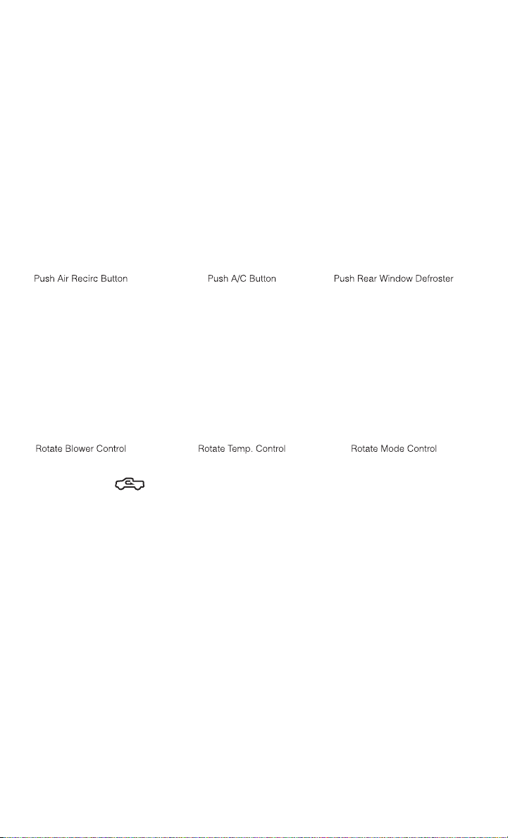
MANUAL CLIMATE CONTROLS WITHOUT TOUCH-SCREEN
Air Recirculation /Max A/C
• Rotate the Temperature Control to the MAX A/C position to automatically turn on
both Air Conditioning and Recirculation.
• For window defogging, turn the recirculation button off.
• Recirculation is not allowed in defrost
• Recirculation is allowed in floor mode and defrost/floor (mix modes) for approxi-
mately five minutes.
Heated Mirrors
• The mirrors are heated to melt frost or ice. This feature is activated whenever you
turn on the defroster.
OPERATING YOUR VEHICLE
34
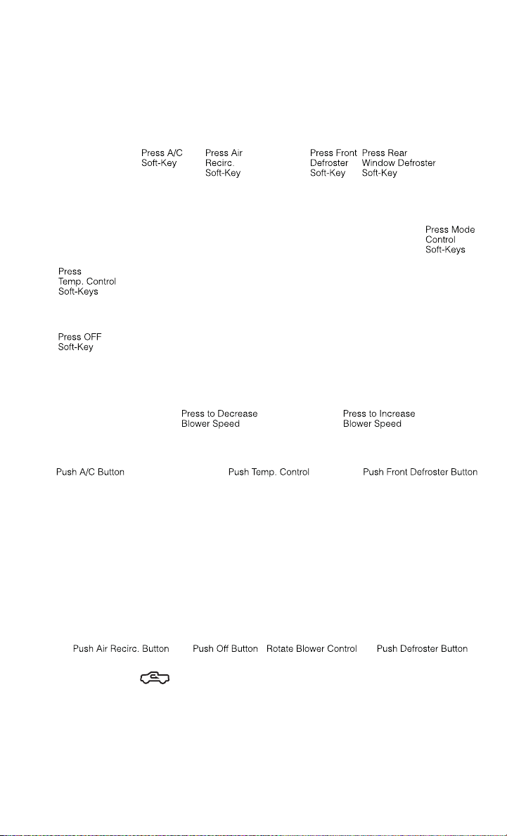
MANUAL CLIMATE CONTROLS WITH TOUCH-SCREEN
Touch-Screen Manual Climate Controls
Climate Control Knobs
Air Recirculation
• Use recirculation for maximum A/C operation.
• For window defogging, turn the recirculation button off.
Heated Mirrors
• The mirrors are heated to melt frost or ice. This feature is activated whenever you
turn on the defroster.
OPERATING YOUR VEHICLE
35
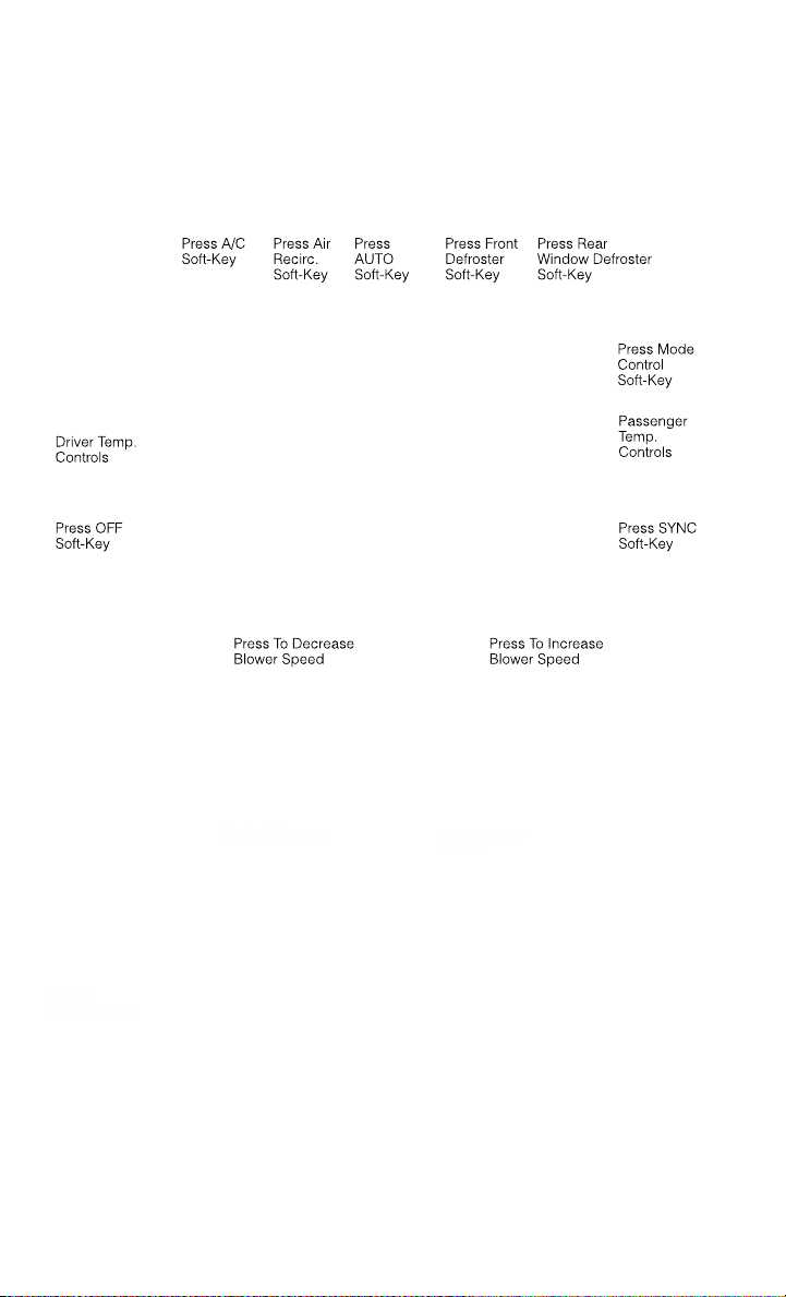
AUTOMATIC CLIMATE CONTROLS WITH TOUCH-SCREEN
Touch-Screen Automatic Climate Controls
Climate Control Knobs
• Press the AUTO button or AUTO soft-key.
• Select the desired temperature by pushing the up or down temperature buttons for
the driver or passenger.
• The system will maintain the set temperature automatically.
OPERATING YOUR VEHICLE
36

Air Conditioning (A/C)
• If the air conditioning button is pressed while in AUTO mode, the system will exit
AUTO mode and stay in A/C. The mode and blower will be set at the closest mode
and blower position that the system was operating in AUTO.
SYNC Temperature Soft-Key
• Touch the SYNC soft-key on the Uconnect
®
Access radio to control the driver and
passenger temperatures simultaneously. Touch the SYNC soft-key a second time
to control the temperatures individually.
Air Recirculation
• Use recirculation for maximum A/C operation.
• For window defogging, turn the recirculation button off.
• If the Recirculation button is pushed while in the AUTO mode, the indicator light
may flash three times to indicate the cabin air is being controlled automatically.
Heated Mirrors
• The mirrors are heated to melt frost or ice. This feature is activated whenever you
turn on the defroster.
PARKSENSE® REAR PARK ASSIST
• If an object is detected behind the rear bumper while the vehicle is in REVERSE,
a warning will display in the instrument cluster and a tone, that changes speed
depending on the distance of the object from the bumper, will sound.
Service The ParkSense® Rear Park Assist System
• When the ParkSense
®
Rear Park Assist System is malfunctioning, the instrument
cluster will actuate a single chime, once per ignition cycle, and it will display the
“CLEAN PARK ASSIST SENSORS” or the “SERVICE PARK ASSIST SYSTEM”
message.
• If “CLEAN PARK ASSIST SENSORS” appears in the Electronic Vehicle Informa-
tion Center (EVIC) and the rear fascia/bumper is clean and clear of snow, ice, mud,
dirt or other obstruction, see your authorized dealer.
• If “SERVICE PARK ASSIST SYSTEM” appears in the EVIC, see your authorized
dealer.
Enable/Disable ParkSense®
• ParkSense
®
can be enabled and disabled with a switch located in the switch bank
of the instrument panel or through the Customer-Programmable Features section
of the EVIC. When the switch is pressed to disable the system, the instrument
cluster will display the “PARK ASSIST SYSTEM OFF” message for approximately
five seconds.
OPERATING YOUR VEHICLE
37

PARKVIEW® REAR BACK-UP CAMERA
• You can see an on-screen image of the rear surroundings of your vehicle whenever
the shift lever is put into REVERSE. The ParkView
®
Rear Back-Up Camera image
will be displayed in the rearview mirror or touchscreen display along with a caution
note to “check entire surroundings” across the top of the screen. After five
seconds this note will disappear.
• If the rearview mirror or touchscreen display appears foggy, clean the ParkView
®
camera located to the left of the tailgate handle.
WARNING!
Drivers must be careful when backing up; even when using the ParkView
®
Rear
Back-Up Camera. Always check carefully behind your vehicle, and be sure to
check for pedestrians, animals, other vehicles, obstructions, or blind spots before
backing up. You must continue to pay attention while backing up. Failure to do so
can result in serious injury or death.
TIRE PRESSURE MONITOR SYSTEM (TPMS) – 2500 MODELS
ONLY
Tire Light Load Inflation Switch Description
• The Tire Pressure Monitoring System on your vehicle has two different tire
pressure settings based on vehicle loading. The Tire Light Load Switch is located
on the Instrument Panel below the climate controls.
• The “Light Load Inflation” and “Max Load Inflation” tire pressures recommended
for your vehicle based on vehicle loading are found on the Supplemental Tire
Pressure Information Label located on the rear face of the driver front door.
• When the vehicle is in the “Light Load Inflation” setting, the Tire Light Load
Inflation switch is On. The indicator light is Off when in the “Max Load Inflation”
setting.
Light Load Inflation (Indicator Light On)
• If the passenger and cargo weights are less than the Light Load Pressure
Definition shown on the Supplemental Tire Pressure Information Label, inflate or
deflate tires to the correct “Light Load Inflation” pressure. If the indicator light is
not on, the mode can be changed by pushing the switch once.
• If the light on the switch flashes On and Off, after the button is pressed to switch
between modes, this indicates conditions are not correct to switch modes. The system
will not allow switching modes until the tire pressures have been set to Light Load
Inflation as indicated on the Supplemental Tire Pressure Information Label.
OPERATING YOUR VEHICLE
38

• IF THE LIGHT STARTS FLASHING TO SHOW LOW AIR PRESSURE, BRING THE AIR
PRESSURE IN THAT TIRE TO THE PLACARD VALUE SHOWN ON THE LABEL ON THE
DRIVER DOOR. NOTE: AFTER INFLATION, THE VEHICLE MAY NEED TO BE DRIVEN FOR UP
TO 20 MINUTES BEFORE THE FLASHING LIGHT WILL GO OFF.
Max Load Inflation (Indicator Light Off)
• If the passenger and cargo weights exceed the Light Load Pressure Definition
shown on the Supplemental Tire Pressure Information Label, adjust tires to the
correct “Max Load Inflation” pressure. If the indicator is on, reset by pushing the
switch once.
• If the tire pressure monitoring light and a “low tire” message appears in the
cluster, inflate the tire pressures to the “Max Load Inflation” setting as indicated
in the Supplemental Tire Pressure Information Label.
• After any tire pressure adjustment, the vehicle may need to be driven for up to
20 minutes at speeds over 15 mph for the tire pressure information to be updated, or
for a low tire pressure warning to go out.
• For additional information, refer to the Owner's Manual on the DVD.
POWER SLIDING REAR WINDOW
• The switch for the power sliding rear
window is located on the overhead
console.
• Push the switch right to open the glass
and pull the switch left to close the
glass.
OPERATING YOUR VEHICLE
39

POWER SUNROOF
• The power sunroof switch is located on
the overhead console.
Opening Sunroof
Express
• Press the switch rearward and release.
The sunroof will fully open and stop
automatically.
Closing Sunroof
Express
• Press the switch forward and release. The sunroof will close automatically from
any position.
Manual Open/Close
• Press and hold the switch rearward to open or forward to close the sunroof. Any
release of the switch will stop the movement, and the sunroof will remain in a
partially open or closed position until the switch is pressed again.
Venting Sunroof
• Press and release the "VENT" button, and the sunroof will open to the vent
position. This is called “Express Vent” and will occur regardless of sunroof
position. During Express Vent operation, any movement of the switch will stop the
sunroof.
Pinch Protection Feature
• This feature will detect an obstruction in the opening of the sunroof during
Express Close operation. If an obstruction in the path of the sunroof is detected,
the sunroof will automatically retract. Remove the obstruction if this occurs. Next,
press the switch forward and release to Express Close.
NOTE:
If three consecutive sunroof close attempts result in Pinch Protect reversals, the
fourth close attempt will be a Manual Close movement with Pinch Protect disabled.
OPERATING YOUR VEHICLE
40

WARNING!
• Never leave children unattended in a vehicle, and do not leave the key in the
ignition switch (or leave the ignition of a vehicle equipped with Keyless
Enter-N-Go™ in the ACC or ON/Run position). Occupants, particularly unat-
tended children, can become entrapped by the power sunroof while operating
the power sunroof switch. Such entrapment may result in serious injury or death.
• In a collision, there is a greater risk of being thrown from a vehicle with an open
sunroof. You could also be severely injured or killed. Always fasten your seat belt
properly and make sure all passengers are properly secured.
• Do not allow small children to operate the sunroof. Never allow your fingers,
other body parts, or any object to project through the sunroof opening. Injury
may result.
WIND BUFFETING
• Wind buffeting can be described as a helicopter-type percussion sound. If
buffeting occurs with the rear windows open, adjust the front and rear windows
together.
• If buffeting occurs with the sunroof open, adjust the sunroof opening, or adjust
any window. This will minimize buffeting.
OPERATING YOUR VEHICLE
41

YOUR VEHICLE'S SOUND SYSTEM
ELECTRONICS
42
ELECTRONICS
43

IDENTIFYING YOUR RADIO
Uconnect® 3.0
• Two hard-keys on either side of the
display
Uconnect® 5.0
• 5” Touch-Screen
• Three hard-keys on either side of the
display
Uconnect® 8.4A
• 8.4” Touch-Screen
• Climate soft key in lower menu bar
• HD Button will NOT be visible on right
side of screen when viewing AM or FM
• SiriusXM Travel Link feature NOT
listed within Apps
Uconnect® 3.0
Uconnect® 5.0
Uconnect® 8.4A
ELECTRONICS
44

Uconnect® 8.4AN
• 8.4” Touch-Screen
• Climate soft key in lower menu bar
• HD Button will be visible on right side
of screen when viewing AM or FM
• SiriusXM Travel Link feature listed
within Apps
Uconnect® Access (AVAILABLE ON Uconnect® 8.4A AND
Uconnect® 8.4AN) (IF EQUIPPED)
• Uconnect
®
Access enhances your ownership and driving experience by connect-
ing your vehicle with built-in 3G cellular connection. Uconnect
®
Access provides:
• The ability to remotely lock/unlock your doors and start your vehicle from
virtually anywhere, with the Uconnect
®
Access App, Owner Connect website
and Uconnect
®
Care (Vehicle must be within the United States and have
network coverage).
• The option to turn your vehicle into a WiFi Hotspot on demand.
• Theft Alarm Notification via text or E-mail.
• Voice Texting so you can compose, send and receive text messages with your
voice while keeping your hands on the wheel. Requires a cell phone that
supports Bluetooth Message Access Profile (MAP).
• Before you drive, familiarize yourself with the easy-to-use Uconnect
®
System.
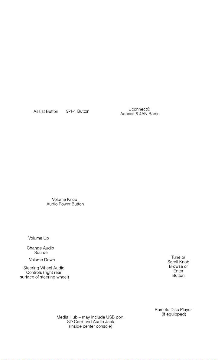
1.
The ASSIST and 9-1-1 buttons are located on your rearview mirror. The ASSIST
Button is used for contacting Roadside Assistance, Vehicle Care and Uconnect
®
Care. The 9-1-1 Button connects you directly to emergency assistance.
NOTE:
Vehicles sold in Canada and Mexico DO NOT have 9-1-1 Call system capabilities. 9-1-1
or other emergency line operators in Canada and Mexico may not answer or respond to
9-1-1 system calls.
2. The Uconnect
®
“Apps” soft-key on the menu bar at the bottom right corner of
the radio touch screen. This is where you can begin your registration process,
manage your Apps and purchase WiFi on demand.
3. The Uconnect
®
Voice Command and Uconnect
®
Phone buttons are located on
the left side of your steering wheel. These buttons let you use your voice to
give commands, make phone calls, send and receive text messages hands-
free, enter navigation destinations, and control your radio and media devices.
Uconnect® 8.4AN
ELECTRONICS
45

Included Trial Period for New Vehicles
• Your new vehicle may come with an included trial period for use of the Uconnect
®
Access Services starting at the date of vehicle purchase (date based on vehicle
sales notification from your dealer). To activate the trial, you must first register
with Uconnect
®
Access. Once registered, Uconnect
®
Access customers can
purchase additional Services and Apps over the lifetime of their vehicle
ownership.
Features and Packages
• After the trial period, you can subscribe to continue your service by visiting the
Uconnect
®
Store located within the Mopar Owner Connect website
(MoparOwnerConnect.com). If you need assistance, U.S. residents can call
Uconnect
®
Care at 855-792-4241.
• For the latest information on packages and pricing information: U.S. residents
visit www.DriveUconnect.com.
Uconnect® Access Registration (U.S. Residents Only)
NOTE:
To unlock the full potential of Uconnect
®
Access in your vehicle, you first need to
register with Uconnect
®
Access.
1. From the parked vehicle with the radio touch screen powered on, select the
“Apps” soft-key located near the bottom right-hand corner of the radio touch
screen.
NOTE:
Should you require assistance anytime during the registration process, simply press
the ASSIST button located on the rear view mirror to be connected with a Uconnect
®
Care agent.
2. Touch Register on the reminder screen or select the “Uconnect Registration”
soft-key which appears in the “Favorites Tab” on the Apps list.
3. The Uconnect
®
Access Registration App will open and display step-by-step
instructions to start your registration.
4. Enter your E-mail address into the radio touch screen.
5. A message will display on the touch screen indicating your mail submission was
accepted. In a few minutes, you will receive an mail which will allow you to
register your vehicle for Uconnect
®
Access. You should open this mail and begin
your Uconnect
®
Access registration within 24 hours.
6. A final message will display on the touch screen allowing you to check on the
status of your mail submission. To exit the registration, press the X in the upper
right corner.
ELECTRONICS
46

NOTE:
For security reasons, this link is valid for 24 hours from the time you submit your mail
address into the radio touch screen. If the link has expired, simply re-enter your mail
address into the Uconnect
®
Registration App on the radio touch screen to receive
another link.
7. Check for an email from Uconnect
®
Access that contains your personalized
registration link. IF you don't see it, check your spam or junk mail folder. Open the
email and click on the link to continue registering.
• The secured registration link will take you through the Uconnect
®
Access
registration process step by step.
• To unlock the full potential of Uconnect
®
Access in your vehicle, you will need to
create or validate an existing Mopar Owner Connect account (previously Owner
Center). Uconnect
®
along with Mopar Owner Connect have joined forces to create
one destination to manage all of your vehicle needs - from managing your
Uconnect
®
Access account to tracking service history and finding recommended
accessories for your vehicle. If you already have a Mopar Owner Connect account,
log in to the website with your existing user name and password. For assistance
with this web based registration process, U.S. residents can call Uconnect
®
Care
at 855-792-4241.
• At this point your vehicle is registered with Uconnect
®
Access. Apps will be
downloaded the next time you start your vehicle. It may take over 30 minutes for
all of the apps to install. If the apps have not appeared after 24 hours, please
contact Uconnect
®
Care. The recommended next steps are to:
• Set up your Payment Account. (Provides the option to purchase packages and
apps, such as WiFi Hotspot)
• Download the Uconnect
®
Access App. (Allows you to utilize the Remote Services
such as Remote Door Unlock)
Download the Uconnect® Access App
• If you own a compatible iOS or Android
®
powered device, the Uconnect Access
App allows you to remotely lock or unlock your doors, start your engine or activate
your horn and lights from virtually anywhere (Vehicle must be within the United
States and have network coverage). You can download the App from Mopar Owner
Connect or from the Apple App or Google Play store. For Uconnect
®
Phone
customer support and to determine if your device is compatible:
• U.S. residents - visit www.UconnectPhone.com or call 1–877–855–8400
• Canadian residents - call 1–800–465–2001 (English) or 1–800–387–9983
(French)
ELECTRONICS
47

Purchasing Apps and WiFi
NOTE:
Apps and WiFi can be purchased from the Uconnect
®
Store within your vehicle, and
online at Mopar Owner Connect. You must first register and set up a Uconnect
®
Payment account.
Purchasing Apps and WiFi for your vehicle
1. With the vehicle parked and the radio powered on, select the “Apps” soft-key
located near the bottom right-hand corner of the radio touch screen.
2. To launch the Uconnect
®
Store, select Tools and then select Uconnect
®
Store.
3. From the Uconnect
®
Store, select the Application (App) you wish to purchase.
4. This will launch the selected App into purchase mode along with providing
additional information. The purchase process begins when you touch the “Buy”
soft-key.
5. The Uconnect
®
Store will display a “Purchase Overview” message confirming the
financial details for the App you are about to purchase. Touch the “Purchase” key
to continue.
6. The Uconnect
®
Store will ask you to “Confirm Payment” using your default
payment method on file in your Payment Account. Touch the Complete key to
continue.
7. The Uconnect
®
Payment Account will then ask for your “Payment Account PIN”.
After entering this four digit PIN, touch the Complete key to make the purchase.
8. You will receive a confirmation message that your purchase has been submitted.
Touch the OK to end the process.
NOTE:
Purchased apps can take up to 30 minutes to download, depending on your vehicle’s
cellular coverage at time of purchase. If your download takes more than 30 minutes,
please contact Uconnect
®
Care by pressing the ASSIST button on the rear view
mirror.
• You can also purchase apps or renew your subscription to a package from the
Mopar Owner Connect website. Log In to the Mopar Owner Connect website
(www.moparownerconnect.com) with your user name and password, and click on
the “Store” tab.
Using Uconnect® Access
Getting Started with Apps
• Applications (Apps) in your Uconnect
®
Access system deliver features and
services that are customized for the driver and are certified by FCA US LLC. Two
different types are:
• Built-In Apps – use the built-in 3G Cellular Network on your Uconnect® radio.
ELECTRONICS
48

• Brought-In Apps – Uconnect
®
Access will allow you to use your own smartphone
or device’s data plan and connection to stream content from FCA US LLC certified
apps into your vehicle and control them using the Uconnect
®
radio touch-screen,
steering wheel controls, and voice recognition.
• Get started with your Uconnect
®
Access apps by pressing the Uconnect
®
“Apps”
soft-key on the menu bar at the bottom right corner of the radio touch screen.
Available apps and features are organized by the tabs on the left of the screen.
• Favorite Apps – this is the default screen when you first press the Apps soft-key,
and is a good place to put the apps you use most frequently. To make an App a
“favorite”, press the settings soft-key to the right of the app, and select “Make a
favorite”.
• Media Apps, Information Apps, and Tools – Organizes your Uconnect
®
Access
apps (when available) into three categories, depending on the type of app.
• Running Apps – press this tab to see which apps are currently running.
Maintaining Your Uconnect® Access Account
Reinstalling an App
• You can easily correct many Application related issues you may be experiencing by
resetting the App back to the factory setting. From the vehicle’s radio touch-
screen, complete the following steps:
1. Touch the Uconnect
®
App and open the Uconnect
®
Store and go to My Apps.
2. In My Apps, select Settings and then Reinstall App and lastly, Continue.
3. Your Apps have been successfully re-installed.
Canceling Your Subscription
• Should you want to cancel your subscription, you can remove your account
information using the same procedure contained in the Selling Your Vehicle
section.
ELECTRONICS
49

Selling Your Vehicle
• When you sell your vehicle, we recommend that you remove your Uconnect
®
Access Account information from the vehicle. You can do this using the radio
touch screen in the vehicle or on the Mopar Owner Connect website
(www.MoparOwnerConnect.com). Removing your account information cancels
your subscription and makes your vehicle factory-ready for a new
owner/subscriber.
1. From your vehicle’s radio touch-screen, select the Uconnect
®
Store from the Apps
icon.
2. Select My apps, then Settings, and then Remove Uconnect
®
Account.
3. Enter your Uconnect
®
Security PIN, select “Proceed to Remove Vehicle from
Uconnect Account”.
• For additional information on Uconnect
®
:
• U.S. residents - visit DriveUconnect.com or call 1-877-855-8400.
In Vehicle Features
1. Assist Call – The rear view mirror contains an ASSIST push button which
automatically connects the vehicle occupants to one of these predefined desti-
nations for immediate support:
• Roadside Assistance Call – If you get a flat tire, or need a tow, you’ll be
connected to someone who can help anytime. Additional fees may apply.
Additional information in this section.
• Uconnect® Access Care – In vehicle support for Uconnect
®
Access System,
Apps and Features.
• Vehicle Care – Total support for your FCA US LLC vehicle.
2. Emergency 9-1-1 Call (If Equipped) – The rear view mirror contains a 9-1-1 button
that, when pressed, will place a call to a local 9-1-1 operator to request help from
local police, fire or ambulance personnel in the event of an emergency. If this
button is accidentally pressed, you will have 10 seconds to cancel the call. To
cancel, press the 9-1-1 Call button again or press the cancellation button shown
on the touch screen. After 10 seconds has passed, the 9-1-1 call will be placed
and only the 9-1-1 operator can cancel it. The LED light on the Rearview Mirror
will turn green once a connection to a 9-1-1 operator has been made. The green
LED light will turn off once the 9-1-1 call is terminated. Have an authorized
dealer service the vehicle if the Rearview Mirror light is continuously red. If a
connection is made between a 9-1-1 operator and your vehicle, you understand and
agree that 9-1-1 operators may, like any other 9-1-1 call, record conversations and
sounds in and near your vehicle upon connection.
3. Roadside Assistance (If Equipped) - If your vehicle is equipped with this feature and
within wireless range, you may be able to connect to Roadside Assistance by
pressing the “Assist” button on the Rearview Mirror. You will be presented with
Assist Care options. Make a selection by touching the prompts displayed on the
ELECTRONICS
50

radio If Roadside Assistance is provided to your vehicle, you agree to be
responsible for any additional roadside assistance service costs that you may
incur. In order to provide Uconnect
®
Services to you, we may record and monitor
your conversations with Roadside Assistance, Uconnect
®
Care or Vehicle Care,
whether such conversations are initiated through the Uconnect
®
Services in your
vehicle, or via a landline or mobile telephone, and may share information
obtained through such recording and monitoring in accordance with regulatory
requirements. You acknowledge, agree and consent to any recording, monitoring
or sharing of information obtained through any such call recordings.
4. Bing™ - Customers have the ability to search for nearby destinations or a point of
interest (POI) either by category or custom search by using keywords (for example,
“Italian restaurant”). Searching can be done by voice or using the touch-screen
keypad. Using the touch-screen, launch Bing™ by selecting the Apps icon, touch
Information Apps tab, and then touch Bing™. Using voice recognition press the
VR button on the steering wheel and say “Launch Bing” or just say “Bing” to
launch the app.
5. Theft Alarm Notification - The Theft Alarm Notification feature notifies you via
E-mail or text message (SMS) when the vehicle’s factory-installed theft alarm
system has been set-off. There are a number of reasons why your alarm may have
been triggered, one of which could be that your vehicle was stolen. If so, please
see the details of the Stolen Vehicle Assistance service below. When you register,
Theft Alarm Notification is automatically set to send you an E-mail at the mail
address you provide should the alarm go off. You may also opt to have a text
message sent to your mobile device.
6. Stolen Vehicle Assistance - If your vehicle is stolen, contact local law enforcement
immediately to file a stolen vehicle report. Once this report has been filed,
Uconnect
®
care can help locate your vehicle. The Uconnect
®
Care agent will ask
for the stolen vehicle report number issued by local law enforcement. Then, using
GPS technology and the built-in wireless connection within your vehicle, the
Uconnect
®
Care agent will be able to locate the stolen vehicle and work with law
enforcement to help recover it. (Vehicle must be within the United States, have
network coverage and must be registered with Uconnect
®
Access with an active
subscription that includes the applicable feature).
7. WiFi Hotspot - WiFi Hotspot is on-demand WiFi 3G connectivity that's built-in and
ready to go whenever you are. Once your vehicle is registered for Uconnect
®
Access, you can purchase a Wifi Hotspot subscription at the Uconnect
®
Store.
After you've made your purchase, turn on your signal and connect your devices.
It's never been easier to bring your home or office with you.
• Your vehicle must have a working electrical system in order for any of the in vehicle
Uconnect
®
features to operate.
ELECTRONICS
51

Uconnect® Access Remote Features
• If you own a compatible iPhone or Android
®
powered device, the Uconnect
®
Access App allows you to remotely lock or unlock your doors, start your engine or
activate your horn and lights from virtually anywhere (Vehicle must be within the
United States, have network coverage and must be registered with Uconnect
®
Access with an active subscription that includes the applicable feature). You can
download the App from from the Apple App or Google Play store. Visit
www.UconnectPhone.com to determine if your device is compatible. For
Uconnect
®
Phone customer support and to determine if your device is compat-
ible:
• U.S. residents - visit www.UconnectPhone.com or call 1–877–855–8400.
1. Remote Start – This feature provides the ability to start the engine on your vehicle,
without the keys and from virtually any distance. You can send a request to your
vehicle in one of two ways:
• Using the Uconnect
®
Access App from a compatible smartphone
• From the Mopar Owner Connect website
• You can also send a command to turn-off an engine that has been remote
started.
• After 15 minutes if you have not entered your vehicle with the key, the engine
will shut off automatically.
• This remote function requires your vehicle to be equipped with a factory-
installed Remote Start system. To use this feature after the Uconnect
®
Access
App is downloaded, login with your user name and Uconnect
®
Security PIN.
• You can set-up notifications for your account to receive an E-mail or text (SMS)
message every time a command is sent. Log in to Mopar Owner Connect
(www.MoparOwnerConnect.com) and click on Edit Profile to manage Uconnect
Notifications.
2. Remote Door Lock/Unlock – This feature provides the ability to lock or unlock the
door on your vehicle, without the keys and from virtually any distance. You can
send a request to your vehicle in one of three ways:
• Using the Uconnect
®
Access App from a compatible smartphone
• From the Mopar Owner Connect website
• By contacting the Uconnect
®
Care on the phone
• To use this feature after the Uconnect
®
Access App is downloaded, login using
your user name and Uconnect Security PIN. Touch the App button on your
smartphone with the closed lock icon to lock the door, and touch the open lock
icon to unlock the driver’s door.
ELECTRONICS
52

• You can set-up notifications for your account to receive an E-mail or text (SMS)
message every time a command is sent. Log in to Mopar Owner Connect
(www.MoparOwnerConnect.com) and click on Edit Profile to manage Uconnect
Notifications.
3. Remote Horn and Lights – It’s easy to locate a vehicle in a dark, crowded or noisy
parking area by activating the horn and lights. It may also help if you need to draw
attention to your vehicle for any reason. You can send a request to your vehicle in
one of three ways:
• Using the Uconnect
®
Access App from a compatible smartphone
• From the Mopar Owner Connect website
• By contacting the Uconnect
®
Care on the phone
• To use this feature after the Uconnect
®
Access App is downloaded, login using
your user name and Uconnect
®
Security PIN. You can set-up notifications for
your account to receive an E-mail or text (SMS) message every time a
command is sent. Log in to Mopar Owner Connect
(www.MoparOwnerConnect.com) and click on Edit Profile to manage Uconnect
Notifications.
4. Voice Texting – Use the sound of your voice to create, listen to and send text
messages. Just tell Uconnect
®
what you want the message to say - it will convert
your voice to text and send the message at your command. Powerful, cloud-based
voice recognition allows you to dictate free form text messages, and send them
from your Bluetooth - enabled phone without taking your hands of the wheel or
focus from the road. Requires a cell phone that supports Bluetooth Message
Access Profile (MAP).
ELECTRONICS
53

WARNING!
• ALWAYS drive safely with your hands on the steering wheel. You have full
responsibility and assume all risks related to the use of the Uconnect
®
features
and applications in this vehicle. Only use Uconnect
®
when it is safe to do so.
Failure to do so may result in an accident involving serious injury or death.
• Ignoring the Rearview Mirror light could mean you may not have 9-1-1 Call
service when you need it. If the Rearview Mirror light is illuminated, have an
authorized dealer service the 9-1-1 Call system immediately.
• The Occupant Restraint Controller (ORC) turns on the Air Bag Warning Light on
the instrument panel if a malfunction is detected in any part of the air bag
system. If the Air Bag Warning Light is illuminated, the air bag system may not
be working properly and the 9-1-1 system may not be able to send a signal to a
9-1-1 operator. If the Air Bag Warning Light is illuminated, have an authorized
dealer service your vehicle immediately.
• If anyone in the vehicle could be in danger (e.g., fire or smoke is visible,
dangerous road conditions or location), do not wait for voice contact from a
9-1-1 operator. All occupants should exit the vehicle immediately and move to
a safe location.
• The 9-1-1 Call system is embedded into the vehicle’s electrical system. Do not
add any aftermarket electrical equipment to the vehicle’s electrical system. This
may prevent your vehicle from sending a signal to initiate an emergency call. To
avoid interference that can cause the 9-1-1 Call system to fail, never add
aftermarket equipment (e.g., two-way mobile radio, CB radio, data recorder,
etc.) to your vehicle’s electrical system or modify the antennas on your vehicle.
IF YOUR VEHICLE LOSES BATTERY POWER FOR ANY REASON (INCLUDING
DURING OR AFTER AN ACCIDENT), THE UCONNECT
®
FEATURES, APPS AND
SERVICES, AMONG OTHERS, WILL NOT OPERATE.
ELECTRONICS
54
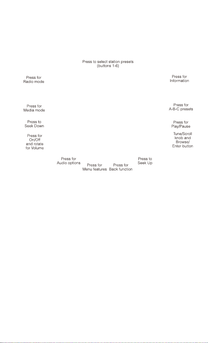
Uconnect® 3.0
Clock Setting
1. Press the Menu button at the bottom of the radio, next select the Time Format
setting and then select Set Time.
2. Adjust the hours or minutes by turning the Tune/Scroll knob, then pressing the
Enter/Browse button to move to the next entry. You can also select 12hr or 24hr
format by turning the Tune/Scroll knob, then pressing the Enter/Browse button on
the desired selection.
3. Once the time is set press the “Back” button to exit the time screen.
Audio
• Press the AUDIO button on the radio faceplate.
• The Audio Menu shows the following options for you to customize your audio
settings.
Mid, Bass, Fade, Balance
• Select the desired setting to adjust, then touch the Enter/Browse button. Turn the
Tune/Scroll knob to adjust the setting + or - 9. Press the back button when done.
ELECTRONICS
55

Radio Operation
Seek Up/Down Buttons
• Press to seek through radio stations in AM, FM or SXM bands.
• Hold either button to bypass stations without stopping.
Store Radio Presets
• The Presets are available for all Radio Modes, and are activated by touching any
of the six Preset buttons.
• When you are receiving a station that you wish to commit into memory, press and
hold the desired numbered button for more that 2 seconds or until you hear a
confirmation beep.
• The Radio stores up to 18 presets in each of the Radio modes. Press the A-B-C
hard-key to select the A, B or C preset list.
Disc Operation
• Your vehicle may have a remote CD player located in the lower center console
storage bin, or in the lower center bench seat bin.
• CD/Disc Mode is entered by either inserting a CD/Disc or by touching the Media
button located on the side of the display. Once in Media Mode, select Disc.
• Gently insert one CD into the CD player with the CD label facing as indicated on
the illustration located on the Disc player.
Seek Up/Down Buttons
• Press to seek through CD tracks.
• Hold either button to bypass tracks without stopping.
USB/Audio Jack (AUX) Operation
USB/iPod®
• USB/iPod
®
Mode is entered by either inserting a USB Jump Drive or iPod
®
cable
into the USB port or by touching the Media button located left of the display. Once
in Media Mode, select USB/iPod
®
for the source.
• Pressing the Media button, then select USB/iPod
®
to change the mode to the USB
device if the device is connected, allowing the music from your portable device to
play through the vehicle's speakers.
Audio Jack (AUX)
• The AUX allows a portable device, such as an MP3 player or an iPod
®
,tobe
plugged into the radio and utilize the vehicle’s audio system, using a 3.5 mm
audio cable, to amplify the source and play through the vehicle’s speakers.
• Pressing the Media button, then touch the Source soft-key and then select AUX to
change the mode to auxiliary device if the audio jack is connected, allowing the
music from your portable device to play through the vehicle's speakers.
ELECTRONICS
56

• The functions of the portable device are controlled using the device buttons, not
the buttons on the radio. The volume may be controlled using the radio or portable
device.
Uconnect® 3.0 Available Media Hubs
Uconnect
3.0
Media Hub
(USB, AUX
Ports)
Media Hub
(SD, USB,
AUX Ports)
Remote USB
Port (Fully
Functional)
Remote USB
Port (Charg-
ing Only)
Dual Charg-
ing Ports
S--OO
S = Standard Equipment
O = Optional Equipment
Uconnect® 5.0
Clock Setting
1. To start the clock setting procedure, perform either of the following:
• Press the More hard-key on the right side of the display, next press the Time
soft-key and then press the Set soft-key.
• Press the Settings hard-key on the right side of the display, then press the
Clock soft-key. The Time setting screen is displayed and the clock can be
adjusted as described in the following procedure.
ELECTRONICS
57

NOTE:
In the Clock Setting Menu you can also select Display Clock. Display Clock turns the
clock display in the status bar on or off.
2. Touch the Up or Down arrows to adjust the hours or minutes, next select the AM
or PM soft-key. You can also select 12hr or 24hr format by touching the desired
soft-key.
3. Once the time is set press the “Done” soft-key to exit the time screen.
Equalizer, Balance and Fade
1. Press the SETTINGS hard-key on the right side of the unit.
2. Then scroll down and press the Audio soft-key to get to the Audio menu.
3. The Audio Menu shows the following options for you to customize your audio
settings.
Equalizer
• Touch the Equalizer soft-key to adjust the Bass, Mid and Treble. Use the + or -
soft-key to adjust the equalizer to your desired settings. Press the back arrow
soft-key when done.
Balance/Fade
• Touch the Balance/Fade soft-key to adjust the sound from the speakers. Use the
arrow soft-key to adjust the sound level from the front and rear or right and left side
speakers. Touch the Center “C” soft-key to reset the balance and fade to the
factory setting. Press the back arrow soft-key when done.
Speed Adjustable
• Touch the Speed Adjusted Volume soft-key to select between OFF, 1, 2 or 3. This
will decrease the radio volume relative to a decrease in vehicle speed. Press the
back arrow soft-key when done.
Loudness
• Touch the Loudness soft-key to select the Loudness feature. When this feature is
activated it improves sound quality at lower volumes.
Radio Operation
Seek Up/Down Buttons
• Press to seek through radio stations in AM, FM or SXM bands.
• Hold either button to bypass stations without stopping.
Store Radio Presets
• When you are receiving a station that you wish to commit into memory, press and
hold the desired numbered soft-key for more that 2 seconds or until you hear a
confirmation beep.
ELECTRONICS
58

• The Radio stores up to 12 presets in each of the Radio modes. 4 presets are visible
at the top of the radio screen. Touching the “all” soft-key on the radio home screen
will display all of the preset stations for that mode.
SiriusXM Premier Over 160 channels
• Get every channel available on your satellite radio, and enjoy all you want, all in
one place. Hear commercial-free music plus sports, news, talk and entertainment.
Get all the premium programming, including Howard Stern, every NFL game,
Oprah Radio
®
, every MLB
®
and NHL
®
game, every NASCAR
®
race, Martha
Stewart and more. And get 20+ extra channels, including SiriusXM Latino,
offering 20 channels of commercial free music, news, talk, comedy, sports and
more dedicated to Spanish language programming.
• To access SiriusXM Satellite Radio, press the “RADIO” hard-key and then the SXM
soft-key.
• SiriusXM services require subscriptions, sold separately after the 12-month trial
included with the new vehicle purchase. If you decide to continue your service at the
end of your trial subscription, the plan you choose will automatically renew and bill at
then-current rates until you call SiriusXM at 1-866-635-2349 for U.S. residents and
1-888-539-7474 for Canadian residents to cancel. See SiriusXM Customer Agreement
for complete terms at www.siriusxm.com for U.S. residents and www.siriusxm.ca for
Canadian residents. All fees and programming subject to change. Our satellite
service is available only to those at least 18 and older in the 48 contiguous USA
and D.C. Our Sirius satellite service is also available in PR (with coverage
limitations). Our Internet radio service is available throughout our satellite service
area and in AK and HI. © 2013 Sirius XM Radio Inc. Sirius, XM and all related
marks and logos are trademarks of Sirius XM Radio Inc.
Disc Operation
• Your vehicle may have a remote CD player located in the lower center console
storage bin, or in the lower center bench seat bin.
• CD/Disc Mode is entered by either inserting a CD/Disc or by touching the Media
button located on the side of the display. Once in Media Mode, select Disc.
• Gently insert one CD into the CD player with the CD label facing as indicated on
the illustration located on the Disc player.
Seek Up/Down Buttons
• Press to seek through Disc tracks.
• Hold either button to bypass tracks without stopping.
Browse
• Touch the browse soft-key to scroll through and select a desired track on the Disc.
Touch the exit soft-key if you wish to cancel the browse function.
ELECTRONICS
59

USB/Audio Jack (AUX)/Bluetooth® Operation
USB/iPod®
• USB/iPod
®
Mode is entered by either inserting a USB Jump Drive or iPod
®
cable
into the USB port or by touching the Media hard-key located left of the display.
Once in Media Mode, touch the source soft-key and select USB/iPod
®
• Pressing the Media hard-key, then touch the source soft-key and then select
USB/iPod
®
to change the mode to the USB device if the device is connected,
allowing the music from your portable device to play through the vehicle's
speakers.
Audio Jack (AUX)
• The AUX allows a portable device, such as an MP3 player or an iPod
®
,tobe
plugged into the radio and utilize the vehicle’s audio system, using a 3.5 mm
audio cable, to amplify the source and play through the vehicle speakers.
• Pressing the Media hard-key, then touch the source soft-key and then select AUX
to change the mode to auxiliary device if the audio jack is connected, allowing the
music from your portable device to play through the vehicle's speakers.
• The functions of the portable device are controlled using the device buttons, not
the buttons on the radio. The volume may be controlled using the radio or portable
device.
Bluetooth®
• If using a Bluetooth
®
- equipped device, you may also be able to stream music to
your vehicle's sound system.
• Press the Media hard-key, then touch the Source soft-key. Select Bluetooth
®
to
change the mode to Bluetooth
®
if the device is paired, allowing the music from
your portable device to play through the vehicle's speakers.
Uconnect® 5.0 Available Media Hubs
Uconnect
®
5.0
Media Hub
(USB, AUX
Ports)
Media Hub
(SD, USB,
AUX Ports)
Remote USB
Port (Fully
Functional)
Remote USB
Port (Charg-
ing Only)
Dual Charg-
ing Ports
S--SO
S = Standard Equipment
O = Optional Equipment
ELECTRONICS
60

VOICE COMMAND QUICK REFERENCE
Uconnect® 5.0 Voice Command Quick Reference
• If the Uconnect Voice Command button exists on your steering wheel, you
have the Voice Command feature, which is optimized for the driver. The Voice
Command feature lets you keep your hands on the wheel, and your eyes on the
road.
• When you press the Voice Command
button located on the steering wheel,
you will hear a beep. After the beep, give your command. If you do not know what
commands to say, you can say “help” and the system will provide options to you.
If you ever wish to interrupt the system while it lists options, press the Voice
Command
button, after the beep, say your command.
NOTE:
All phone oriented voice commands are accessible by first pressing the Phone Pick
Up
button, not the Voice Command button. To end a call, simply press the
Phone Hang Up
button. In some vehicles, the Phone Pickup button serves
the dual purpose of ending calls as well.
Voice Command (VR) User TIPs
• To hear available commands, press the Uconnect
®
Voice Command button and
say “Help”. You will hear available commands for the menu displayed.
• At any time, you can say the words “Cancel” or “Help”. These commands are
universal and can be used from virtually any menu. All other specific commands
can be used depending upon the active application.
• You can interrupt the system prompts at any time by pressing the Uconnect
®
Voice
Command button while the system is speaking. After the beep, you can say a
command.
• You can ‘chain’ commands together for faster results. Say “Call Joe Doe mobile”,
for example.
• For best performance, adjust the rearview mirror to provide at least 1⁄2 in (1 cm)
gap between the overhead console (if equipped) and the mirror.
• Always wait for the beep before speaking.
• Speak normally, without pausing, just as you would speak to a person sitting a few
feet/meters away from you.
• Make sure that no one other than you is speaking during a Voice Command period.
Steering Wheel Buttons
• You can control many of your radio features using your voice. Press either the VR
or Phone Pick Up button on your steering wheel.
ELECTRONICS
61

Available Radio Button Voice Commands
Types of Voice
Commands
Available
Steering Wheel
Buttons to Press:
Radio Mode Media Mode Phone Mode
Uconnect
®
Voice Command
(VR) Button
AM/FM & Satel-
lite Band Con-
trol
Media Devices
Control
-
GENERAL
Uconnect
®
Phone Pick Up
Button
--
Call Initiation,
Call Manage-
ment, Pre-
formatted Voice
Text Reply
Voice Command Examples – Uconnect® 5.0
GENERAL
Anytime
“Go to Radio” (Media, Phone) – Com-
pass, Settings, and More functions are
not Voice Command accessible
“Cancel”
“Help” (to listen to suggested commands
specific to current need
“Repeat”
RADIO
AM/FM
“Tune to AM950”, “Tune to 95.5FM (pre-
set 5)
Satellite Band Control
“Tune to Satellite Channel 80's on 8”,
Tune to Satellite Channel 32 (preset 4)
MEDIA
Media Devices Control (Functionality is
dependent on compatibility between de-
vices and radio)
“Browse” (show) “artist” (albums, music)
“Show paired phones” (devices)
“Play song – Maple Leaf Rag” (artist -
Scott Joplin, genre - rock, album - Rag-
time Favorites)
ELECTRONICS
62

PHONE
Call Initiation (Requires that phone has
been Bluetooth
®
paired with radio
“Dial 123-456-7890” (phone number)
“Call John Smith mobile” (home, office,
other)
“Redial”
“Show outgoing” (recent) “calls”
Call Management
“Search for John Smith” (any contact
name in address book)
“Show (display list) contacts”
Voice Text Reply (Radio audibly recognizes
these 18 pre-formatted SMS messages as
you speak)
Forward one of 18 pre-formatted SMS
messages to incoming calls/text mes-
sages:
“Yes.”
“No.”
“Okay.”
“I can’t talk right now.”
“Call me.”
“I’ll call you later.”
“I’m on my way.”
“Thanks.”
“I’ll be late.”
“I will be <number> minutes late.”
“See you in <number> minutes”
“Stuck in traffic.”
“Start without me.”
“Where are you?”
“Are you there yet?”
“I need directions.”
“I’m lost.”
“See you later.”
ELECTRONICS
63
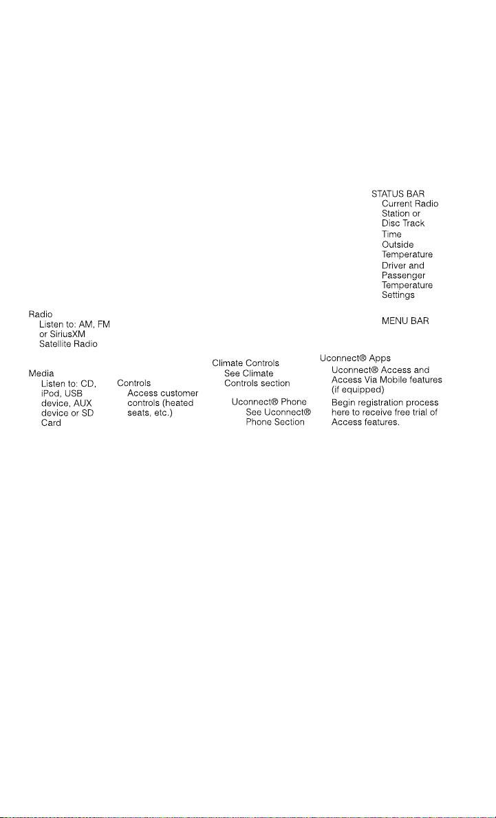
Uconnect® 8.4A
Uconnect® 8.4A AT A GLANCE
Displaying the Time
• If the time is not currently displayed on the radio or player main page, touch the
Settings soft-key or the Apps soft-key and then the Settings soft-key. In the
Settings list, touch the Clock soft-key then touch the check box next to Show Time
in Status Bar.
Setting the Time
• Model 8.4AN synchronizes time automatically via GPS, so should not require any
time adjustment. If you do need to set the time manually, follow the instructions
below for Model 8.4A.
• For Model 8.4A, turn the unit on, then touch the time display at the top of the
screen. Touch Yes.
• If the time is not displayed at the top of the screen, touch the Settings soft-key or
the Apps soft-key and then the Settings soft-key. In the Settings screen, touch the
Clock soft-key, then check or uncheck this option.
• Touch + or – next to Set Time Hours and Set Time Minutes to adjust the time.
• If these features are not available, uncheck the Sync with GPS box.
• Touch X to save your settings and exit out of the Clock Setting screen.
ELECTRONICS
64

Audio Settings
• Touch of the Audio soft-key to activate the Audio settings screen to adjust
Balance\Fade, Equalizer, and Speed Adjusted Volume.
• You can return to the Radio screen by touching the X located at the top right.
Balance/Fade
• Touch the Balance/Fade soft-key to Balance audio between the front speakers or
fade the audio between the rear and front speakers.
• Touching the Front, Rear, Left, or Right soft-keys or touch and drag the blue
Speaker Icon to adjust the Balance/Fade.
Equalizer
• Touch the Equalizer soft-key to activate the Equalizer screen.
• Touch the + or - soft-keys, or by touching and dragging over the level bar for each
of the equalizer bands. The level value, which spans between plus or minus 9, is
displayed at the bottom of each of the Bands.
Speed Adjusted Volume
• Touch the Speed Adjusted Volume soft-key to activate the Speed Adjusted Volume
screen. The Speed Adjusted Volume is adjusted by touching the + and - buttons
or by touching and dragging over the level bar. This alters the automatic
adjustment of the audio volume with variation to vehicle speed.
RADIO
• To access the Radio mode, touch the Radio soft-key at the lower left of the screen.
ELECTRONICS
65

Selecting Radio Stations
• Touch the desired radio band (AM, FM or SXM) soft-key.
Seek Up/Seek Down
• Touch the Seek arrow soft-keys for less than two seconds to seek through radio
stations.
• Touch and hold either arrow soft-key for more than two seconds to bypass stations
without stopping. The radio will stop at the next listenable station once the arrow
soft-key is released.
Direct Tune
• Tune directly to a radio station by pressing the Tune soft-key on the screen, and
entering the desired station number.
Store Radio Presets
• Your radio can store 12 total preset stations. They are shown at the top of your
screen. To see all 12 stations, press the arrow soft-key at the top right of the screen
to toggle between the six presets.
• To set a station into memory press and hold the desired numbered soft-key for
more than two seconds or until you hear a confirmation beep.
SiriusXM PREMIER OVER 160 CHANNELS
• Get every channel available on your satellite radio, and enjoy all you want, all in
one place. Hear commercial-free music plus sports, news, talk and entertainment.
Get all the premium programming, including Howard Stern, every NFL game,
Oprah Radio
®
, every MLB
®
and NHL
®
game, every NASCAR
®
race, Martha
Stewart and more. And get 20+ extra channels, including SiriusXM Latino,
offering 20 channels of commercial free music, news, talk, comedy, sports and
more dedicated to Spanish language programming.
• To access SiriusXM Satellite Radio, touch the SXM soft-key on the main Radio
screen.
• The following describes features that are available when in SiriusXM Satellite
Radio mode.
Seek Up/Seek Down
• Touch the Seek arrow soft-keys for less than two seconds to seek through channels
in SXM mode.
• Touch and hold either arrow soft-key for more than two seconds to bypass channels
without stopping. The radio will stop at the next listenable channel once the arrow
soft-key is released.
Direct Tune
• Tune directly to a SXM channel by pressing the Tune soft-key on the screen, and
entering the desired station number.
ELECTRONICS
66

Jump
• Automatically tells you when Traffic & Weather for a favorite city is available, and
gives you the option to switch to that channel. Touch Jump to activate the feature.
After listening to Traffic and Weather, touch Jump again to return to the previous
channel.
Fav
• Activates the favorites menu. You can add up to 50 favorite artists or songs. Just
touch Add Fav Artist or Add Fav Song while the song is playing. You will then be
alerted any time one of these songs, or works by these artists, is playing on other
SiriusXM channels.
SiriusXM Parental Controls
• You can skip or hide certain channels from view if you do not want access to them.
Touch the More soft-key, then the Settings soft-key, next touch the Sirius Setup
soft-key, then select Channel Skip. Touch the box, check-mark, next to the
channel you want skipped. They will not show up in normal usage.
• SiriusXM also offers the option to permanently block selected channels. Call
(1-888-601-6297 for U.S. customers, 1-877-438-9677 for Canadian custom-
ers) and request the Family-Friendly Package.
Browse
• Lets you browse the SiriusXM channel listing or Genre listing. Favorites, Game
Zone, Weather and Jump settings also provide a way to browse the SiriusXM
channel list.
Browse Sub-
Menu
Sub-Menu Description
All Shows the channel listing.
Genre Provides a list of all genres, and lets you jump to a channel within the
selected genre.
Presets Lets you scroll the list of Preset satellite channels. Touch the channel, or
press Enter on the Tune knob, to go to that channel. Touch the trash can
icon to delete a preset. Your presets are also shown at the top of the main
Satellite Radio screen.
Favorites Lets you manage artists and songs in the Favorites list and configure Alert
Settings to let you know when favorite songs or artists are playing on other
channels. Also, view a list of channels airing any of your Favorites.
Game Zone Provides alerts when your favorite sports teams are starting a game which
is being aired on other SiriusXM channels, or when their game score is
announced. You can select and manage your Teams list here, and
configure alerts.
Jump Lets you select your favorite cities for Traffic & Weather information,
which is used by the Jump feature on the main satellite radio screen.
ELECTRONICS
67

Replay
• Lets you replay up to 44 minutes of the content of the current SiriusXM channel.
Replay
Option
Option Description
Play/Pause Touch to Pause content playback. Touch Pause/Play again to resume
playback.
Rewind/RW Rewinds the channel content in steps of five seconds. Touch and hold to
rewind continuously, then release to begin playing content at that point.
Fast
Forward/FW
Forwards the content, and works similarly to Rewind/RW. However, Fast
Forward/FW can only be used when content has been previously rewound.
Replay Time Displays the amount of time in the upper center of the screen by which
your content lags the Live channel.
Live Resumes playback of Live content at any time while replaying rewound
content.
• SiriusXM services require subscriptions, sold separately after the 12-month trial
included with the new vehicle purchase. If you decide to continue your service at the
end of your trial subscription, the plan you choose will automatically renew and bill at
then-current rates until you call SiriusXM at 1-866-635-2349 for U.S. residents and
1-888-539-7474 for Canadian residents to cancel. See SiriusXM Customer Agreement
for complete terms at www.siriusxm.com (US residents) or www.siruisxm.ca (Canadian
residents). All fees and programming subject to change. Our satellite service is
available only to those at least 18 and older in the 48 contiguous USA and D.C.
Our Sirius satellite service is also available in PR (with coverage limitations). Our
Internet radio service is available throughout our satellite service area and in AK
and HI. © 2013 Sirius XM Radio Inc. Sirius, XM and all related marks and logos
are trademarks of Sirius XM Radio Inc.
Disc Operation
• Your vehicle may have a remote CD player located in the lower center console
storage bin, or in the lower center bench seat bin.
• CD/Disc Mode is entered by either inserting a CD/Disc or by touching the Media
button located on the side of the display. Once in Media Mode, select Disc.
• Gently insert one CD into the CD player with the CD label facing as indicated on
the illustration located on the Disc player.
Seek Up/Down Buttons
• Press to seek through Disc tracks.
• Hold either button to bypass tracks without stopping.
Browse
• Touch the browse soft-key to scroll through and select a desired track on the Disc.
Touch the exit soft-key if you wish to cancel the browse function.
ELECTRONICS
68

MEDIA HUB – PLAYING iPod/USB/MP3 DEVICES
• There are many ways to play music from iPod
®
/MP3 players or USB devices
through your vehicle's sound system. Touch your Media soft-key to begin.
Audio Jack (AUX)
• The AUX allows a portable device, such as an MP3 player or an iPod
®
,tobe
plugged into the radio and utilize the vehicle’s sound system, using a 3.5 mm
audio cable, to amplify the source and play through the vehicle speakers.
• Touching the AUX soft-key will change the mode to auxiliary device if the audio
jack is connected, allowing the music from your portable device to be heard
through the vehicle's speakers. In order to activate the AUX, plug in the audio jack.
• The functions of the portable device are controlled using the device buttons. The
volume may be controlled using the radio or portable device.
• To route the audio cable out of the center console, use the access cut out in the
front of the console.
USB Port
• Connect your iPod
®
or compatible device using a USB cable into the USB Port.
USB Memory sticks with audio files can also be used. Audio from the device can
be played on the vehicles sound system while providing metadata (artist, track
title, album, etc.) information on the radio display.
• When connected, the iPod
®
/compatible USB device can be controlled using the
radio or Steering Wheel Audio Controls to play, skip to the next or previous track,
browse, and list the contents.
• The iPod
®
battery charges when plugged into the USB port (if supported by the
specific device).
• To route the USB/iPod
®
cable out of the center console, use the access cut out.
ELECTRONICS
69

NOTE:
When connecting your iPod
®
device for the first time, the system may take several
minutes to read your music, depending on the number of files. For example, the
system will take approximately 5 minutes for every 1000 songs loaded on the device.
Also during the reading process, the Shuffle and Browse functions will be disabled.
This process is needed to ensure the full use of your iPod
®
features and only happens
the first time it is connected. After the first time, the reading process of your iPod
®
will take considerably less time unless changes are made or new songs are added to
the playlist.
• The USB port supports certain Mini, Classic, Nano, Touch, and iPhone
®
devices.
The USB port also supports playing music from compatible external USB Mass
Storage Class memory devices. Some iPod
®
software versions may not fully
support the USB port features. Please visit Apple’s website for iPod
®
software
updates.
SD Card
• Play songs stored on an SD card inserted into the SD card slot.
• Song playback can be controlled using the radio or Steering Wheel Audio Controls
to play, skip to the next or previous track, browse, and list the contents.
Bluetooth® Streaming Audio
• If equipped with Uconnect
®
Voice Command, your Bluetooth-equipped iPod
®
devices, cell phones or other media players, may also be able to stream music to
your vehicle's sound system. Your connected device must be Bluetooth-
compatible, and paired with your system (see Uconnect
®
Phone for pairing
instructions). You can access the music from your connected Bluetooth
®
device
by touching the Bluetooth
®
soft-key while in Media mode.
Uconnect® 8.4A & 8.4AN Available Media Hubs
Uconnect
®
8.4A &
8.4AN
Media Hub
(USB, AUX
Ports)
Media Hub
(SD, USB,
AUX Ports)
Remote USB
Port (Fully
Functional)
Remote USB
Port (Charg-
ing Only)
Dual Charg-
ing Ports
- SSOO
S = Standard Equipment
O = Optional Equipment
ELECTRONICS
70

iPod®/CD/AUX CONTROLS
• The iPod
®
/CD/AUX controls are accessed by touching the desired soft-key dis-
played on the side of the screen and choosing between Disc, AUX, iPod
®
,
Bluetooth or SD Card.
NOTE:
Uconnect
®
will usually automatically switch to the appropriate mode when some-
thing is first connected or inserted into the system.
NAVIGATION (DEALER-ACTIVATED OPTION)
• Your Uconnect
®
8.4A is “Navigation-Ready”, and can be equipped with Naviga-
tion at an extra cost. See your dealer for details.
• The information in this section is only applicable if the feature has been equipped.
If so equipped, you will see a Nav soft-key at the bottom of the touch-screen.
ELECTRONICS
71
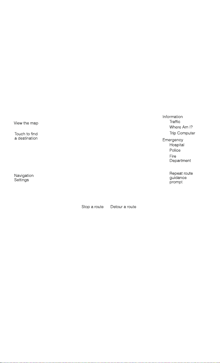
Changing the Navigation Voice Prompt Volume
1. Touch the View Map soft-key from the Nav Main Menu.
2. With the map displayed, touch the Settings soft-key in the lower right area of the
screen.
3. In the Settings menu, touch the Guidance soft-key.
4. In the Guidance menu, adjust the Nav Volume by touching the + or – soft-keys.
Finding Points of Interest
• From the main Navigation menu, touch the Where To? soft-key, then touch the
Points of Interest soft-key.
• Select a Category and then a subcategory, if necessary.
• Select your destination and touch the Yes soft-key.
Finding a Place by Spelling the Name
• From the Main Navigation Menu touch the Where to? soft-key, touch the Points of
Interest soft-key and then touch the Spell Name soft-key.
• Enter the name of your destination.
• Touch the Done soft-key.
• Select your destination and touch the Yes soft-key.
ELECTRONICS
72
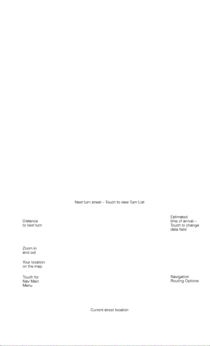
Entering a Destination Address
• From the main Navigation menu touch the Where To? soft-key, then touch the
Address soft-key.
• Follow the on-screen prompts to enter the address and touch the Yes soft-key.
• Destination entry is not available while your vehicle is in motion. However, you can
also use Voice Command to enter an address while moving. See Voice Command
Tips for more information.
Setting Your Home Location
• Touch the NAV soft-key in the menu bar to access the Navigation system and the
Main Navigation menu.
• Touch the Where To? soft-key, then touch the Go Home soft-key.
• You may enter your address directly, use your current location as your home
address, or choose from recently found locations.
• To delete your Home location (or other saved locations) so you can save a new
Home location, touch the Where To? soft-key from the Main Navigation menu,
then touch the Go Home soft-key, and in the Yes screen touch the Options soft-key.
In the Options menu touch Clear Home. Set a new Home location by following the
previous instructions.
Go Home
• A Home location must be saved in the system. From the Main Navigation menu,
touch the Where To? soft-key, then touch the Go Home soft-key.
ELECTRONICS
73

• Your route is marked with a blue line on the map. If you depart from the original
route, your route is recalculated. A speed limit icon could appear as you travel on
major roadways.
Adding a Stop
• To add a stop you must be navigating a route.
• Touch the Menu soft-key to return to the Main Navigation menu.
• Touch the Where To? soft-key, then search for the extra stop. When another
location has been selected, you can choose to cancel your previous route, add as
the first destination or add as the last destination.
• Touch the desired selection and touch the Yes soft-key.
Taking a Detour
• To take a detour you must be navigating a route.
• Touch the Detour soft-key.
NOTE:
If the route you are currently taking is the only reasonable option, the device might
not calculate a detour.
• For more information, see your Uconnect
®
User's Manual.
Uconnect® Phone (Bluetooth® HANDS FREE CALLING)
• If the Uconnect
®
Phone Button exists on your steering wheel, then you have
the Uconnect
®
Phone features.
• The Uconnect
®
Phone is a voice-activated, hands-free, in-vehicle communica-
tions system with Voice Command Capability (see Voice Command section).
• The Uconnect
®
Phone allows you to dial a phone number with your mobile phone
using simple voice commands or using screen soft-keys.
• Refer to the Understand The Features Of Your Vehicle section of your vehicle's
Owner's Manual on the DVD for further details.
NOTE:
The Uconnect
®
Phone requires a mobile phone equipped with the Bluetooth
®
Hands-Free Profile, Version 1.0 or higher. For Uconnect
®
Customer Support: U.S.
residents visit www.UconnectPhone.com or call 1–877–855–8400. Canadian Resi-
dents: call 1-800-465–2001 (English) or 1-800-387-9983 (French).
Pairing a Phone
• To use the Uconnect
®
Phone feature, you must first pair your Bluetooth
®
phone
with the Uconnect
®
system.
Start pairing procedure on the radio
• Touch the Phone soft-key and then the Settings soft-key. Next, touch Add Device.
• Uconnect
®
Phone will display an “In progress” screen while the system is
connecting.
ELECTRONICS
74

Start pairing procedure on mobile phone
• Search for available devices on your Bluetooth
®
enabled mobile phone. This is
usually within Settings or Options under “Bluetooth”. See your mobile phone’s
manual for details.
• When your phone finds the system, select “Uconnect” as the paired device. You
may be prompted by your phone to download the phonebook. This is so you can
make calls by saying the name of your contact (PBAP-Phone Book Access Profile).
Complete the pairing procedure
• When prompted on the phone, enter the 4-digit PIN number shown on the
Uconnect
®
Screen.
• If your phone asks you to accept a connection request from Uconnect, select
“Yes”. If available, check the box telling it not to ask again – that way your phone
will automatically connect each time you start the vehicle.
Select the mobile phone's priority level
• When the pairing process has successfully completed, the system will prompt you
to choose whether or not this is your favorite phone. Selecting Yes will make this
phone the highest priority. This phone will take precedence over other paired
phones within range. Only one phone can be paired at a time.
• You are now ready to make hands-free calls. Press the Uconnect
®
Phone button on
your steering wheel to begin.
Making A Phone Call
• Press the Uconnect
®
Phone button .
• After the BEEP, say “dial” then the number (or “call” then the name as listed in
your phone; see Phonebook).
NOTE:
You can also initiate a call by using the touch-screen on the Phone main screen.
Receiving A Call – Accept (And End)
• When an incoming call rings/is announced on Uconnect
®
, press the Phone button
.
• To end a call, press the Phone button
.
Mute (Or Unmute) Microphone During Call
• During a call, touch the mute soft-key on the Phone main screen to mute and
unmute the call.
Transfer Ongoing Call Between Handset And Vehicle
• During an on-going call, touch the Transfer soft-key on the Phone main screen to
transfer an on-going call between handset and vehicle.
ELECTRONICS
75

Common Phone Commands (Examples)
• “Call John Smith”
• “Call John Smith mobile”
• “Dial 1 248 555 1212
• “Call Emergency”
• “Call Towing Assistance”
• “Redial”
Phonebook
• Uconnect
®
radios will automatically download your phonebook from your paired
phone, if this feature is supported by your phone. Entries are updated each time
that the phone is connected. If your phone book entries do not appear, check the
settings on your phone. Some phones require you to enable this feature manually.
• Your phonebook can be browsed on your radio screen, but editing can only be done
on your phone. To browse, touch the Phone soft-key, then the Phonebook soft-key.
• Favorite phonebook entries can be saved as Favorites for quicker access. Favorites
are shown at the top of your main phone screen.
Voice Command Tips
• Using complete names (i.e; Call John Doe vs. Call John) will result in greater
system accuracy.
• You can “chain” commands together for faster results. Say “Call John Doe,
mobile”, for example.
• If you are listening to available voice command options, you do not have to listen
to the entire list. When you hear the command that you need, press the
button on the steering wheel, wait for the beep and say your command.
Changing The Volume
• Start a dialogue by pressing the Phone button
, then say a command for
example - "Help".
• Use the radio ON/OFF VOLUME rotary knob to adjust the volume to a comfortable
level while the Uconnect
®
system is speaking. Please note the volume setting for
Uconnect
®
is different than the audio system.
NOTE:
To access help, press the Uconnect
®
Phone button on the steering wheel and
say "help." Touch the display or push either
or button and say "cancel" to
cancel the help session.
ELECTRONICS
76

Voice Text Reply
• Uconnect
®
Phone can read or send new text messages on your mobile phone.
• Your mobile phone must be MAP (Message Access Profile) compatible to support
SMS via Bluetooth
®
to use this feature. If the Uconnect
®
Phone determines your
phone is not compatible with SMS messaging over Bluetooth
®
the “Messaging”
button will be greyed out and the feature will not be available for use.
NOTE:
For mobile phone compatibility and pairing instructions, please visit
www.UconnectPhone.com
WARNING!
• Any voice commanded system should be used only in safe driving conditions
following applicable laws regarding phone use. Your attention should be focused
on safely operating the vehicle. Failure to do so may result in a collision causing
you and others to be severely injured or killed.
• In an emergency, to use Uconnect
®
Phone, your mobile phone must be:
• turned on,
• paired to Uconnect
®
Phone,
• and have network coverage.
VOICE COMMAND QUICK REFERENCE
Uconnect® 8.4A Voice Command Quick Reference
• If the Uconnect
®
Voice Command
button exists on your steering wheel, you
have the Voice Command feature, which is optimized for the driver. The Voice
Command feature lets you keep your hands on the wheel, your eyes on the road,
and control navigation and media sources.
• When you press the Voice Command
button located on the steering wheel,
you will hear a beep. After the beep, give your command. If you do not know what
commands to say, you can say “help” and the system will provide options to you.
If you ever wish to interrupt the system while it lists options, press the Voice
Command
button, after the beep, say your command.
NOTE:
All phone oriented voice commands are accessible by first pressing the Phone Pick
Up
button, not the Voice Command button. To end a call, simply press the
Phone Hang Up
button. In some vehicles, the Phone Pickup button
serves the dual purpose of ending calls as well.
ELECTRONICS
77

Voice Command (VR) User TIPs
• To hear available commands, press the Uconnect
®
Voice Command button and
say “Help”. You will hear available commands for the menu displayed.
• At any time, you can say the words “Cancel” or “Help”. These commands are
universal and can be used from virtually any menu. All other specific commands
can be used depending upon the active application.
• You can interrupt the system prompts at any time by pressing the Uconnect
®
Voice
Command button while the system is speaking. After the beep, you can say a
command.
• You can ‘chain’ commands together for faster results. Say “Navigate to 1234 Main
Street Hometown, California”, for example.
• For best performance, adjust the rearview mirror to provide at least ½ in (1 cm)
gap between the overhead console (if equipped) and the mirror.
• Always wait for the beep before speaking.
• Speak normally, without pausing, just as you would speak to a person sitting a few
feet/meters away from you.
• Make sure that no one other than you is speaking during a Voice Command period.
Steering Wheel Buttons
• You can control many of your radio features using your voice. Press either the VR
or Phone Pick Up button on your steering wheel.
Available Radio Soft–Key Voice Commands
ELECTRONICS
78

Types of
Voice
Com-
mands
Avail-
able
Steering
Wheel
Buttons to
Press:
(1)Radio
Mode
(2)Media
Mode
(3)Cli-
mate
Controls
(4)Navi-
gation
(5)Phone
Mode
(6)APPS
Uconnect
®
Voice
Command
(VR) But-
ton
AM/FM &
Satellite
Band
Control
Media
Devices
Control
Tempera-
ture Con-
trol
Destina-
tion Se-
lection
and View
- Yelp
®
GENERAL
Uconnect
®
Phone
Pick Up
Button
----
Call Ini-
tiation,
Call
Manage-
ment,
Pre-
format-
ted Voice
Text Re-
ply
-
Voice Command Examples – Uconnect® 8.4A
GENERAL
Anytime
“Go to Radio” (Media, Climate, Naviga-
tion, Phone, Apps) – Settings, and Con-
trols are not Voice Command accessible
“Cancel”
“Help” (to listen to suggested commands
specific to current need
“Repeat”
“Launch Yelp
®
” – Required 1st voice
command to launch Yelp
®
app
“Yelp
®
Search” – Required 2nd voice com-
mand to activate app functionality using
Steering Wheel Voice Control Button
RADIO
AM/FM
“Tune to AM950”, “Tune to 95.5FM
(preset 5)
Satellite Band Control
“Tune to Satellite Channel 80's on 8”,
Tune to Satellite Channel 32 (preset 4)
MEDIA
Media Devices Control (Functionality is
dependent on compatibility between de-
vices and radio)
“Browse” (show) “artist” (albums, music)
“Show paired phones” (devices)
“Play song – Maple Leaf Rag” (artist -
Scott Joplin, genre - rock, album - Rag-
time Favorites)
“Shuffle” – available with iPod
®
, USB
and SD Card
ELECTRONICS
79

CLIMATE
Temperature Control
“Set temperature to 70 degrees” – single
climate zone vehicles
“Set driver” (passenger) “temperature to
75 degrees” – dual climate zone vehicles
NAVIGATION
Destination Selection & View
“Go Home” – destination previously de-
fined by driver
“Repeat guidance” – hear the last naviga-
tion prompt
“Cancel Route”
“View Map”
PHONE
Call Initiation (Requires that phone has
been Bluetooth
®
paired with radio
“Dial 123-456-7890” (phone number)
“Call John Smith mobile” (home, office,
other)
“Redial”
“Show outgoing” (recent) “calls”
Call Management
“Search for John Smith” (any contact
name in address book)
“Show (display list) contacts”
Voice Texting (Available during trial period
or if subscribed to Uconnect
®
Access Ad-
vantage)
Create a text message using Voice Com-
mand Capability
“Send a message to John Smith
(123-456-7890)”
“Show Messages”
“Listen to” (view) “number 4”
“Reply”
“Forward text” (message) “to John
Smith” (phone type, number)
ELECTRONICS
80

PHONE
Voice Text Reply (Radio audibly recognizes
these 18 pre-formatted SMS messages as
you speak)
Forward one of 18 pre-formatted SMS
messages to incoming calls/text mes-
sages:
“Yes.”
“No.”
“Okay.”
“I can’t talk right now.”
“Call me.”
“I’ll call you later.”
“I’m on my way.”
“Thanks.”
“I’ll be late.”
“I will be <number> minutes late.”
“See you in <number> minutes”
“Stuck in traffic.”
“Start without me.”
“Where are you?”
“Are you there yet?”
“I need directions.”
“I’m lost.”
“See you later.”
APPS
Yelp®(Yelp
®
adds it's own audible
prompts, and response time varies de-
pending on carrier coverage speed)
“Launch Yelp
®
” – Required 1st voice
command to launch Yelp
®
app
“Yelp
®
Search” – Required 2nd voice
command to activate app functionality
using Steering Wheel Voice Control But-
ton
“Hotel” (restaurant, gas station, mail,
hospital) – for nearest desired general
POI
“Italian restaurants” – for nearest speci-
fied POI category
“Hotels” (restaurants, hospitals, Star-
bucks) “in Miami” (location) – specified
distance POI
ELECTRONICS
81
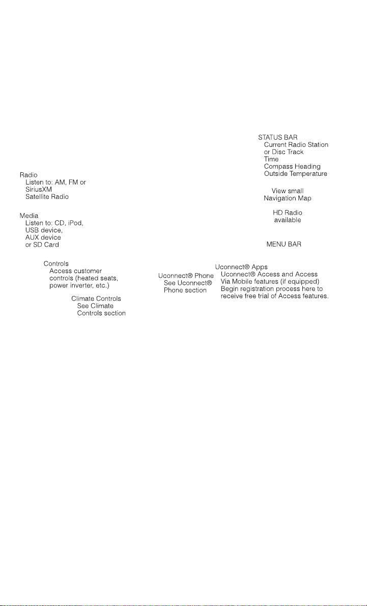
Uconnect® 8.4AN
Uconnect® 8.4AN AT A GLANCE
Displaying the Time
• If the time is not currently displayed on the radio or player main page, touch the
Settings soft-key or the Apps soft-key and then the Settings soft-key. In the
Settings list, touch the Clock soft-key then touch the check box next to Show Time
in Status Bar.
Setting the Time
• Model 8.4AN synchronizes time automatically via GPS, so should not require any
time adjustment. If you do need to set the time manually, follow the instructions
below for Model 8.4A.
• For Model 8.4A, turn the unit on, then touch the time display at the top of the
screen. Touch Yes.
• If the time is not displayed at the top of the screen, touch Settings soft-key or the
Apps soft-key and then the Settings soft-key. In the Settings screen, touch the
Clock soft-key, then check or uncheck this option.
• Touch + or – next to Set Time Hours and Set Time Minutes to adjust the time.
• If these features are not available, uncheck the Sync with GPS box.
• Touch X to save your settings and exit out of the Clock Setting screen.
ELECTRONICS
82

Audio Settings
• Touch of the Audio soft-key to activate the Audio settings screen to adjust
Balance\Fade, Equalizer, and Speed Adjusted Volume.
• You can return to the Radio screen by touching the X located at the top right.
Balance/Fade
• Touch the Balance/Fade soft-key to Balance audio between the front speakers or
fade the audio between the rear and front speakers.
• Touching the Front, Rear, Left, or Right soft-keys or touch and drag the blue
Speaker Icon to adjust the Balance/Fade.
Equalizer
• Touch the Equalizer soft-key to activate the Equalizer screen.
• Touch the + or - soft-keys, or by touching and dragging over the level bar for each
of the equalizer bands. The level value, which spans between plus or minus 9, is
displayed at the bottom of each of the Bands.
Speed Adjusted Volume
• Touch the Speed Adjusted Volume soft-key to activate the Speed Adjusted Volume
screen. The Speed Adjusted Volume is adjusted by touching the + and - buttons
or by touching and dragging over the level bar. This alters the automatic
adjustment of the audio volume with variation to vehicle speed.
RADIO
• To access the Radio mode, touch the Radio soft-key at the lower left of the screen.
ELECTRONICS
83

Selecting Radio Stations
• Touch the desired radio band (AM, FM or SXM) soft-key.
Seek Up/Seek Down
• Touch the Seek arrow soft-keys for less than two seconds to seek through radio
stations.
• Touch and hold either arrow soft-key for more than two seconds to bypass stations
without stopping. The radio will stop at the next listenable station once the arrow
soft-key is released.
Direct Tune
• Tune directly to a radio station by pressing the “Tune” button on the screen, and
entering the desired station number.
Store Radio Presets
• Your radio can store 12 total preset stations. They are shown at the top of your
screen. To see all 12 stations, press the arrow soft-key at the top right of the screen
to toggle between the six presets.
• To set a station into memory press and hold the desired numbered soft-key for
more than two seconds or until you hear a confirmation beep.
HD Radio
• HD Radio technology (available on Uconnect 8.4AN) operates similar to conven-
tional radio except it allows broadcasters to transmit a high-quality digital signal.
• With an HD radio receiver, the listener is provided with a clear sound that
enhances the listening experience. HD radio can also transmit data such as song
title or artist.
SiriusXM PREMIER OVER 160 CHANNELS
• Get every channel available on your satellite radio, and enjoy all you want, all in
one place. Hear commercial-free music plus sports, news, talk and entertainment.
Get all the premium programming, including Howard Stern, every NFL game,
Oprah Radio
®
, every MLB
®
and NHL
®
game, every NASCAR
®
race, Martha
Stewart and more. And get 20+ extra channels, including SiriusXM Latino,
offering 20 channels of commercial free music, news, talk, comedy, sports and
more dedicated to Spanish language programming.
• To access SiriusXM Satellite Radio, touch the SXM soft-key on the main Radio
screen.
• The following describes features that are available when in SiriusXM Satellite
Radio mode.
ELECTRONICS
84

Seek Up/Seek Down
• Touch the Seek arrow soft-keys for less than two seconds to seek through channels
in SXM mode.
• Touch and hold either arrow soft-key for more than two seconds to bypass
channels without stopping. The radio will stop at the next listenable channel once
the arrow soft-key is released.
Direct Tune
• Tune directly to a SXM channel by pressing the Tune soft-key on the screen, and
entering the desired station number.
Jump
• Automatically tells you when Traffic & Weather for a favorite city is available, and
gives you the option to switch to that channel. Touch Jump to activate the feature.
After listening to Traffic and Weather, touch Jump again to return to the previous
channel.
Fav
• Activates the favorites menu. You can add up to 50 favorite artists or songs. Just
touch Add Fav Artist or Add Fav Song while the song is playing. You will then be
alerted any time one of these songs, or works by these artists, is playing on other
SiriusXM channels.
SiriusXM Parental Controls
• You can skip or hide certain channels from view if you do not want access to them.
Touch the More soft-key, then the Settings soft-key, next touch the Sirius Setup
soft-key, then select Channel Skip. Touch the box, check-mark, next to the
channel you want skipped. They will not show up in normal usage.
• SiriusXM also offers the option to permanently block selected channels. Call
(1-888-601-6297 for U.S. customers, 1-877-438-9677 for Canadian custom-
ers) and request the Family-Friendly Package.
Browse
• Lets you browse the SiriusXM channel listing or Genre listing. Favorites, Game
Zone, Weather and Jump settings also provide a way to browse the SiriusXM
channel list.
ELECTRONICS
85

Browse
Sub-Menu
Sub-Menu Description
All Shows the channel listing.
Genre Provides a list of all genres, and lets you jump to a channel within the
selected genre.
Presets Lets you scroll the list of Preset satellite channels. Touch the channel, or
press Enter on the Tune knob, to go to that channel. Touch the trash can
icon to delete a preset. Your presets are also shown at the top of the main
Satellite Radio screen.
Favorites Lets you manage artists and songs in the Favorites list and configure Alert
Settings to let you know when favorite songs or artists are playing on other
channels. Also, view a list of channels airing any of your Favorites.
Game Zone Provides alerts when your favorite sports teams are starting a game which
is being aired on other SiriusXM channels, or when their game score is
announced. You can select and manage your Teams list here, and
configure alerts.
Jump Lets you select your favorite cities for Traffic & Weather information,
which is used by the Jump feature on the main satellite radio screen.
Replay
• Lets you replay up to 44 minutes of the content of the current SiriusXM channel.
Replay
Option
Option Description
Play/Pause Touch to Pause content playback. Touch Pause/Play again to resume
playback.
Rewind/RW Rewinds the channel content in steps of five seconds. Touch and hold to
rewind continuously, then release to begin playing content at that point.
Fast
Forward/FW
Forwards the content, and works similarly to Rewind/RW. However, Fast
Forward/FW can only be used when content has been previously rewound.
Replay Time Displays the amount of time in the upper center of the screen by which
your content lags the Live channel.
Live Resumes playback of Live content at any time while replaying rewound
content.
• SiriusXM services require subscriptions, sold separately after the 12-month trial
included with the new vehicle purchase. If you decide to continue your service at the
end of your trial subscription, the plan you choose will automatically renew and bill at
then-current rates until you call SiriusXM at 1-866-635-2349 for U.S. residents and
1-888-539-7474 for Canadian residents to cancel. See SiriusXM Customer Agreement
for complete terms at www.siriusxm.com (US residents) or www.siruisxm.ca (Canadian
residents). All fees and programming subject to change. Our satellite service is
available only to those at least 18 and older in the 48 contiguous USA and D.C.
Our Sirius satellite service is also available in PR (with coverage limitations). Our
Internet radio service is available throughout our satellite service area and in AK
and HI. © 2013 Sirius XM Radio Inc. Sirius, XM and all related marks and logos
are trademarks of Sirius XM Radio Inc.
ELECTRONICS
86

Disc Operation
• Your vehicle may have a remote CD player located in the lower center console
storage bin, or in the lower center bench seat bin.
• CD/Disc Mode is entered by either inserting a CD/Disc or by touching the Media
button located on the side of the display. Once in Media Mode, select Disc.
• Gently insert one CD into the CD player with the CD label facing as indicated on
the illustration located on the Disc player.
Seek Up/Down Buttons
• Press to seek through Disc tracks.
• Hold either button to bypass tracks without stopping.
Browse
• Touch the browse soft-key to scroll through and select a desired track on the Disc.
Touch the exit soft-key if you wish to cancel the browse function.
MEDIA HUB – PLAYING iPod/USB/MP3 DEVICES
• There are many ways to play music from iPod
®
/MP3 players or USB devices
through your vehicle's sound system. Touch your Media soft-key to begin.
ELECTRONICS
87

Audio Jack (AUX)
• The AUX allows a portable device, such as an MP3 player or an iPod
®
,tobe
plugged into the radio and utilize the vehicle’s sound system, using a 3.5 mm
audio cable, to amplify the source and play through the vehicle speakers.
• Touching the AUX soft-key will change the mode to auxiliary device if the audio
jack is connected, allowing the music from your portable device to be heard
through the vehicle's speakers. To activate the AUX, plug in the audio jack.
• The functions of the portable device are controlled using the device buttons. The
volume may be controlled using the radio or portable device.
• To route the audio cable out of the center console, use the access cut out in the
front of the console.
USB Port
• Connect your iPod
®
or compatible device using a USB cable into the USB Port.
USB Memory sticks with audio files can also be used. Audio from the device can
be played on the vehicles sound system while providing metadata (artist, track
title, album, etc.) information on the radio display.
• When connected, the iPod
®
/compatible USB device can be controlled using the
radio or Steering Wheel Audio Controls to play, skip to the next or previous track,
browse, and list the contents.
• The iPod
®
battery charges when plugged into the USB port (if supported by the
specific device).
• To route the USB/iPod
®
cable out of the center console, use the access cut out.
NOTE:
When connecting your iPod
®
device for the first time, the system may take several
minutes to read your music, depending on the number of files. For example, the
system will take approximately five minutes for every 1000 songs loaded on the
device. Also during the reading process, the Shuffle and Browse functions will be
disabled. This process is needed to ensure the full use of your iPod
®
features and
only happens the first time it is connected. After the first time, the reading process
of your iPod
®
will take considerably less time unless changes are made or new songs
are added to the playlist.
• The USB port supports certain Mini, Classic, Nano, Touch, and iPhone
®
devices.
The USB port also supports playing music from compatible external USB Mass
Storage Class memory devices. Some iPod
®
software versions may not fully
support the USB port features. Please visit Apple’s website for iPod
®
software
updates.
SD Card
• Play songs stored on an SD card inserted into the SD card slot.
• Song playback can be controlled using the radio or Steering Wheel Audio Controls
to play, skip to the next or previous track, browse, and list the contents.
ELECTRONICS
88
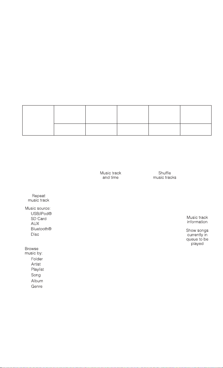
Bluetooth® Streaming Audio
• If equipped with Uconnect
®
Voice Command, your Bluetooth-equipped iPod
®
devices, cell phones or other media players, may also be able to stream music to
your vehicle's sound system. Your connected device must be Bluetooth-
compatible, and paired with your system (see Uconnect
®
Phone for pairing
instructions). You can access the music from your connected Bluetooth
®
device
by touching the Bluetooth
®
soft-key while in Media mode.
Uconnect® 8.4A & 8.4AN Available Media Hubs
Uconnect
®
8.4A &
8.4AN
Media Hub
(USB, AUX
Ports)
Media Hub
(SD, USB,
AUX Ports)
Remote USB
Port (Fully
Functional)
Remote USB
Port (Charg-
ing Only)
Dual Charg-
ing Ports
- SSOO
S = Standard Equipment
O = Optional Equipment
iPod®/CD/AUX CONTROLS
• The iPod
®
/CD/AUX controls are accessed by touching the desired soft-key dis-
played on the side of the screen and choosing between Disc, AUX, iPod
®
,
Bluetooth or SD Card.
NOTE:
Uconnect
®
will usually automatically switch to the appropriate mode when some-
thing is first connected or inserted into the system.
ELECTRONICS
89
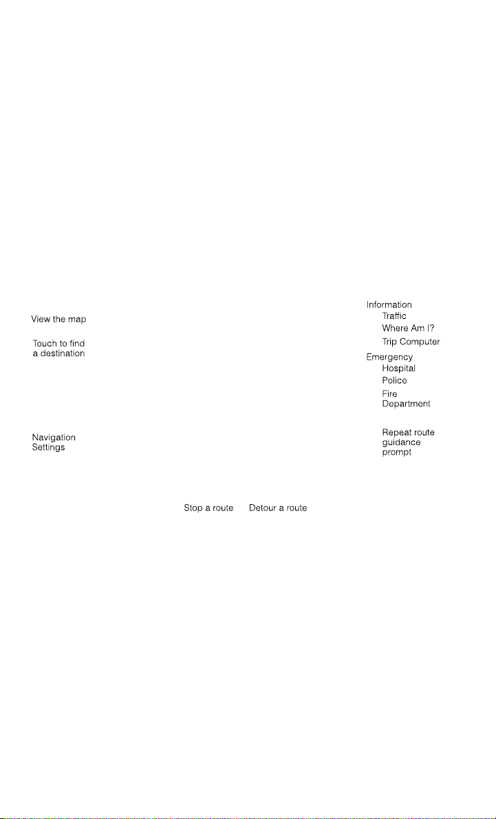
NAVIGATION
• Touch the Nav soft-key in the menu bar to access the Navigation system.
Changing the Navigation Voice Prompt Volume
1. Touch the View Map soft-key from the Nav Main Menu.
2. With the map displayed, touch the Settings soft-key in the lower right area of the
screen.
3. In the Settings menu, touch the Guidance soft-key.
4. In the Guidance menu, adjust the Nav Volume by touching the + or – soft-keys.
Finding Points of Interest
• From the main Navigation menu, touch the Where To? soft-key, then touch the
Points of Interest soft-key.
• Select a Category and then a subcategory, if necessary.
• Select your destination and touch the Yes soft-key.
ELECTRONICS
90

Finding a Place by Spelling the Name
• From the Main Navigation Menu touch the Where to? soft-key, touch the Points of
Interest soft-key, then touch the Spell Name soft-key.
• Enter the name of your destination.
• Touch the List soft-key.
• Select your destination and touch the Yes soft-key.
Entering a Destination Address
• From the main Navigation menu touch the Where To? soft-key, then touch the
Address soft-key.
• Follow the on-screen prompts (country, state/province, city, street) to enter the
address and touch the Yes soft-key.
NOTE:
Destination entry is not available while your vehicle is in motion. However, you can
also use Voice Commands to enter an address while moving. Refer to Common
Navigation Voice Commands in the Uconnect
®
Voice Command section.
Setting Your Home Location
• Touch the NAV soft-key in the menu bar to access the Navigation system and the
Main Navigation menu.
• Touch the Where To? soft-key, then touch the Go Home soft-key.
• You may enter your address directly, use your current location as your home
address, or choose from recently found locations.
• To delete your Home location (or other saved locations) so you can save a new
Home location, touch the Where To? soft-key from the Main Navigation menu,
then touch the Go Home soft-key, and in the Yes screen touch the Options soft-key.
In the Options menu touch the Clear Home soft-key. Set a new Home location by
following the previous instructions.
ELECTRONICS
91
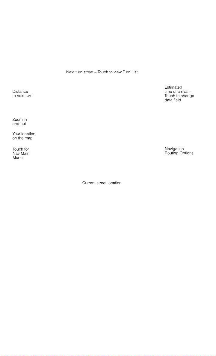
Go Home
• A Home location must be saved in the system. From the Main Navigation menu,
touch the Where To? soft-key, then touch the Go Home soft-key.
• Your route is marked with a blue line on the map. If you depart from the original
route, your route is recalculated. A speed limit icon could appear as you travel on
major roadways.
Adding a Stop
• To add a stop you must be navigating a route.
• Touch the Menu soft-key to return to the Main Navigation menu.
• Touch the Where To? soft-key, then search for the extra stop. When another
location has been selected, you can choose to cancel your previous route, add as
the first destination or add as the last destination.
• Touch the desired selection and touch the Yes soft-key.
Taking a Detour
• To take a detour you must be navigating a route.
• Touch the Detour soft-key.
NOTE:
If the route you are currently taking is the only reasonable option, the device may not
calculate a detour. For more information, see your Uconnect
®
User's Manual.
ELECTRONICS
92

SiriusXM TRAFFIC (US Market Only)
Don't drive through traffic. Drive around it.
• Avoid congestion before you reach it. By enhancing your vehicle's navigation
system with the ability to see detailed traffic information, you can pinpoint traffic
incidents, determine average traffic speed and estimate travel time along your
route. Since the service is integrated with a vehicle's navigation system, SiriusXM
Traffic can help drivers pick the fastest route based on traffic conditions.
1. Detailed information on traffic speed, accidents, construction, and road closings.
2. Traffic information from multiple sources, including police and emergency
services, cameras and road sensors.
3. Coast-to-coast delivery of traffic information.
4. View conditions for points along your route and beyond. Available in over
130 markets.
SiriusXM TRAVEL LINK (US Market Only)
• In addition to delivering over 130 channels of the best sports, entertainment, talk,
and commercial-free music, SiriusXM offers premium data services that work in
conjunction with compatible navigation systems. SiriusXM Travel Link brings a
wealth of useful information into your vehicle and right to your fingertips.
• Weather -- Check variety of local and national weather information from radar
maps to current and 5-day forecast.
• Fuel Prices -- Check local gas and diesel prices in your area and route to the
station of your choice.
• Sports Scores -- In-game and final scores as well as weekly schedules.
• Movie Listings -- Check local movie theatres and listings in your area and route to
the theater of your choice.
• SiriusXM Travel Link feature is completely integrated into your vehicle. A few
minutes after you start your vehicle, Travel Link information arrives and updates in
the background. You can access the information whenever you like, with no
waiting.
• To access SiriusXM Travel Link, touch Apps soft-key, then the SiriusXM Travel Link
soft-key.
NOTE:
SiriusXM Travel Link requires a subscription, sold separately after the 1 year trial
subscription included with your vehicle purchase.
ELECTRONICS
93

• SiriusXM Travel Link is only available in the United States.
Fuel Prices
Check local gas and diesel prices in your area and route to the station of
your choice.
Movie
Listings
Check local movie theatres and listings in your area and route to the
theater of your choice.
Sports
Scores
In-game and final scores as well as weekly schedules.
Weather
Check variety of local and national weather information from radar maps
to current and 5-day forecast.
Uconnect® Phone (Bluetooth® HANDS FREE CALLING)
• If the Uconnect
®
Phone Button exists on your steering wheel, then you have
the Uconnect
®
Phone features.
• The Uconnect
®
Phone is a voice-activated, hands-free, in-vehicle communica-
tions system with Voice Command Capability (see Voice Command section).
• The Uconnect
®
Phone allows you to dial a phone number with your mobile phone
using simple voice commands or using screen soft-keys.
• Refer to the Understand The Features Of Your Vehicle section of your vehicle's
Owner's Manual on the DVD for further details.
NOTE:
The Uconnect
®
Phone requires a mobile phone equipped with the Bluetooth
®
Hands-Free Profile, Version 1.0 or higher. For Uconnect
®
Customer Support: U.S.
residents visit www.UconnectPhone.com or call 1–877–855–8400. Canadian Resi-
dents: call 1-800-465–2001 (English) or 1-800-387-9983 (French).
Pairing a Phone
• To use the Uconnect
®
Phone feature, you must first pair your Bluetooth
®
phone
with the Uconnect
®
system.
Start pairing procedure on the radio
• Touch the Phone soft-key and then the Settings soft-key. Next, touch Add Device.
• Uconnect
®
Phone will display an “In progress” screen while the system is
connecting.
Start pairing procedure on mobile phone
• Search for available devices on your Bluetooth
®
enabled mobile phone. This is
usually within Settings or Options under “Bluetooth”. See your mobile phone’s
manual for details.
• When your phone finds the system, select “Uconnect” as the paired device. You
may be prompted by your phone to download the phonebook. This is so you can
make calls by saying the name of your contact (PBAP-Phone Book Access Profile).
ELECTRONICS
94

Complete the pairing procedure
• When prompted on the phone, enter the 4-digit PIN number shown on the
Uconnect
®
Screen.
• If your phone asks you to accept a connection request from Uconnect, select
“Yes”. If available, check the box telling it not to ask again – that way your phone
will automatically connect each time you start the vehicle.
Select the mobile phone's priority level
• When the pairing process has successfully completed, the system will prompt you
to choose whether or not this is your favorite phone. Selecting Yes will make this
phone the highest priority. This phone will take precedence over other paired
phones within range. Only one phone can be paired at a time.
• You are now ready to make hands-free calls. Press the Uconnect
®
Phone button on
your steering wheel to begin.
Making A Phone Call
• Press the Uconnect
®
Phone button .
• After the BEEP, say “dial” then the number (or “call” then the name as listed in
your phone; see Phonebook).
NOTE:
You can also initiate a call by using the touch-screen on the Phone main screen.
Receiving A Call – Accept (And End)
• When an incoming call rings/is announced on Uconnect
®
, press the Phone button
.
• To end a call, press the Phone button
.
Mute (Or Unmute) Microphone During Call
• During a call, touch the mute soft-key on the Phone main screen to mute and
unmute the call.
Transfer Ongoing Call Between Handset And Vehicle
• During an on-going call, touch the Transfer soft-key on the Phone main screen to
transfer an on-going call between handset and vehicle.
Common Phone Commands (Examples)
• “Call John Smith”
• “Call John Smith mobile”
• “Dial 1 248 555 1212
• “Call Emergency”
• “Call Towing Assistance”
• “Redial”
ELECTRONICS
95

Phonebook
• Uconnect
®
radios will automatically download your phonebook from your paired
phone, if this feature is supported by your phone. Entries are updated each time
that the phone is connected. If your phone book entries do not appear, check the
settings on your phone. Some phones require you to enable this feature manually.
• Your phonebook can be browsed on your radio screen, but editing can only be done
on your phone. To browse, touch the Phone soft-key, then the Phonebook soft-key.
• Favorite phonebook entries can be saved as Favorites for quicker access. Favorites
are shown at the top of your main phone screen.
Voice Command Tips
• Using complete names (i.e; Call John Doe vs. Call John) will result in greater
system accuracy.
• You can “chain” commands together for faster results. Say “Call John Doe,
mobile”, for example.
• If you are listening to available voice command options, you do not have to listen
to the entire list. When you hear the command that you need, press the
button on the steering wheel, wait for the beep and say your command.
Changing The Volume
• Start a dialogue by pressing the Phone button
, then say a command for
example - "Help".
• Use the radio ON/OFF VOLUME rotary knob to adjust the volume to a comfortable
level while the Uconnect
®
system is speaking. Please note the volume setting for
Uconnect
®
is different than the audio system.
NOTE:
To access help, press the Uconnect
®
Phone button on the steering wheel and
say "help." Touch the display or push either
or button and say "cancel" to
cancel the help session.
Voice Text Reply
• Uconnect
®
Phone can read or send new text messages on your mobile phone.
• Your mobile phone must be MAP (Message Access Profile) compatible to support
SMS via Bluetooth
®
to use this feature. If the Uconnect
®
Phone determines your
phone is not compatible with SMS messaging over Bluetooth
®
the “Messaging”
button will be greyed out and the feature will not be available for use.
NOTE:
For mobile phone compatibility and pairing instructions, please visit
www.UconnectPhone.com
ELECTRONICS
96

WARNING!
• Any voice commanded system should be used only in safe driving conditions
following applicable laws regarding phone use. Your attention should be focused
on safely operating the vehicle. Failure to do so may result in a collision causing
you and others to be severely injured or killed.
• In an emergency, to use Uconnect
®
Phone, your mobile phone must be:
• turned on,
• paired to Uconnect
®
Phone,
• and have network coverage.
VOICE COMMAND QUICK REFERENCE
Uconnect® 8.4AN Voice Command Quick Reference
• If the Uconnect
®
Voice Command button exists on your steering wheel, you
have the Voice Command feature, which is optimized for the driver. The Voice
Command feature lets you keep your hands on the wheel, and your eyes on the
road.
• When you press the Voice Command
button located on the steering wheel,
you will hear a beep. After the beep, give your command. If you do not know what
commands to say, you can say “help” and the system will provide options to you.
If you ever wish to interrupt the system while it lists options, press the Voice
Command
button, after the beep, say your command.
NOTE:
All phone oriented voice commands are accessible by first pressing the Phone Pick
Up
button, not the Voice Command button. To end a call, simply press the
Phone Hang Up
button. In some vehicles, the Phone Pickup button
serves the dual purpose of ending calls as well.
Voice Command (VR) User TIPs
• To hear available commands, press the Uconnect
®
Voice Command button and
say “Help”. You will hear available commands for the menu displayed.
• At any time, you can say the words “Cancel” or “Help”. These commands are
universal and can be used from virtually any menu. All other specific commands
can be used depending upon the active application.
• You can interrupt the system prompts at any time by pressing the Uconnect
®
Voice
Command button while the system is speaking. After the beep, you can say a
command.
• You can ‘chain’ commands together for faster results. Say “Call Joe Doe mobile”,
for example.
• For best performance, adjust the rearview mirror to provide at least 1⁄2 in (1 cm)
gap between the overhead console (if equipped) and the mirror.
• Always wait for the beep before speaking.
ELECTRONICS
97

• Speak normally, without pausing, just as you would speak to a person sitting a few
feet/meters away from you.
• Make sure that no one other than you is speaking during a Voice Command period.
Steering Wheel Buttons
• You can control many of your radio features using your voice. Press either the VR
or Phone Pick Up button on your steering wheel.
Available Radio Soft–Key Voice Commands
ELECTRONICS
98

Types of
Voice
Com-
mands
Avail-
able
Steering
Wheel But-
tons to
Press:
(1) Radio
Mode
(2) Me-
dia Mode
(3) Cli-
mate
Controls
(4) Navi-
gation
(5)
Phone
Mode
(6) APPS
Uconnect
®
Voice Com-
mand (VR)
Button
AM/FM
& Satel-
lite
Band
Control
Media
Devices
Control
Tem-
perature
Control
Destina-
tion Se-
lection
and
View
- Yelp
®
GENERAL
Uconnect
®
Phone Pick
Up Button
----
Call Ini-
tiation,
Call
Manage-
ment,
Pre-
format-
ted
Voice
Text Re-
ply
-
Voice Command Examples – Uconnect® 8.4AN
GENERAL
Anytime
“Go to Radio” (Media, Climate, Naviga-
tion, Phone, Apps) – Settings, and Con-
trols are not Voice Command accessible
“Cancel”
“Help” (to listen to suggested commands
specific to current need
“Repeat”
“Launch Yelp
®
” – Required 1st voice
command to launch Yelp
®
app
“Yelp
®
Search” – Required 2nd voice
command to activate app functionality
using Steering Wheel Voice Control But-
ton
RADIO
AM/FM
“Tune to AM950”, “Tune to 95.5FM (pre-
set 5)
Satellite Band Control
“Tune to Satellite Channel 80's on 8”,
Tune to Satellite Channel 32 (preset 4)
ELECTRONICS
99

MEDIA
Media Devices Control (Functionality is
dependent on compatibility between de-
vices and radio)
“Browse” (show) “artist” (albums, music)
“Show paired phones” (devices)
“Play song – Maple Leaf Rag” (artist -
Scott Joplin, genre - rock, album - Rag-
time Favorites)
“Shuffle” – available with iPod, USB and
SD Card
CLIMATE
Temperature Control
“Set temperature to 70 degrees” – single
climate zone vehicles
“Set driver” (passenger) “temperature to
75 degrees” – dual climate zone vehicles
NAVIGATION
Destination Selection & View
“Navigate to” (Destination) 123 Any
Street, Any town, Any State (any full ad-
dress)
“Go Home” – destination previously de-
fined by driver
“Repeat guidance” – hear the last naviga-
tion prompt
“Cancel Route”
“View Map”
PHONE
Call Initiation (Requires that phone has
been Bluetooth
®
paired with radio
“Dial 123-456-7890” (phone number)
“Call John Smith mobile” (home, office,
other)
“Redial”
“Show outgoing” (recent) “calls”
Call Management
“Search for John Smith” (any contact
name in address book)
“Show (display list) contacts”
Voice Texting (Available during trial period
or if subscribed to Uconnect
®
Access Ad-
vantage)
Create a text message using Voice Com-
mand Capability
“Send a message to John Smith (123-
456-7890)”
“Show Messages”
“Listen to” (view) “number 4”
“Reply”
“Forward text” (message) “to John
Smith” (phone type, number)
ELECTRONICS
100

PHONE
Voice Text Reply (Radio audibly recognizes
these 18 pre-formatted SMS messages as
you speak)
Forward one of 18 pre-formatted SMS
messages to incoming calls/text mes-
sages:
“Yes.”
“No.”
“Okay.”
“I can’t talk right now.”
“Call me.”
“I’ll call you later.”
“I’m on my way.”
“Thanks.”
“I’ll be late.”
“I will be <number> minutes late.”
“See you in <number> minutes”
“Stuck in traffic.”
“Start without me.”
“Where are you?”
“Are you there yet?”
“I need directions.”
“I’m lost.”
“See you later.”
APPS
SiriusXM Travel Link (Traffic function is
not voice command accessible within
SiriusXM Travel Link
“Show Fuel prices”
“Show Current Weather” – provides ac-
cess to Forecast as well
“Show Weather map” – multiple map for-
mats available
“Show Sports”
“Show Movie listings”
“Show My favorites”
Yelp® (Yelp
®
adds it's own audible
prompts, and response time varies de-
pending on carrier coverage speed)
“Launch Yelp
®
” – Required 1st voice
command to launch Yelp
®
app
“Yelp
®
Search” – Required 2nd voice
command to activate app functionality
using Steering Wheel Voice Control But-
ton
“Hotel” (restaurant, gas station, mail,
hospital) – for nearest desired general
POI
“Italian restaurants” – for nearest speci-
fied POI category
“Hotels” (restaurants, hospitals, Star-
bucks) “in Miami” (location) – specified
distance POI
ELECTRONICS
101

STEERING WHEEL AUDIO CONTROLS
• The steering wheel audio controls are
located on the rear surface of the
steering wheel.
Right Switch
• Press the switch up or down to in-
crease or decrease the volume.
• Press the button in the center to
change modes AM/FM/CD/SXM.
Left Switch
• Press the switch up or down to search
for the next listenable station or select
the next or previous CD track.
• Press the button in the center to select
the next preset station (radio) or to change CDs if equipped with a CD Changer.
ELECTRONIC VEHICLE INFORMATION CENTER (EVIC)
The EVIC features a driver interactive display that is located in the instrument
cluster. Pressing the controls on the left side of the steering wheel allows the driver
to select vehicle information and Personal Settings. For additional information, refer
to “Programmable Features” in this guide.
• Press and release the UP
button
to scroll upward through the main
menus (Fuel Economy, Vehicle Info,
Tire PSI, Cruise, Messages, Trip Info,
Vehicle Speed and Turn Menu Off) and
sub menus.
• Press and release the DOWN
button to scroll downward through the
main menus and sub menus.
• Press and release the RIGHT
but-
ton for access to main menus, sub
menus or to select a personal setting in the setup menu. Press and hold the RIGHT
button for two seconds to reset features.
• Press the BACK/LEFT
button to scroll back to a previous menu or sub menu.
Compass Calibration
• This compass is self-calibrating, which eliminates the need to set the compass
manually. When the vehicle is new, the compass may appear erratic and the EVIC
will display “CAL” until the compass is calibrated.
ELECTRONICS
102

• You may also calibrate the compass by completing one or more 360 degree turns
(in an area free from large metal or metallic objects) until the “CAL” message
displayed in the EVIC turns off. The compass will now function normally.
PROGRAMMABLE FEATURES
Programmable Features
The EVIC can be used to view or change the following settings. Press the UP
or
DOWN
button until System Setup displays, then press the RIGHT button.
Scroll through the settings using the UP or DOWN buttons. Press the RIGHT
button to change the setting. Press the BACK/LEFT button to scroll back to a
previous menu or sub menu.
• Radio Info • Trip Info
• Fuel Economy Info • Tire Pressure
• Cruise Control Info • Vehicle Info
• Digital Vehicle Speed • Stored Warning Messages
• Stop/Start • Turn Menu OFF
• Screen Setup • Trailer Tow
Uconnect® Access Customer Programmable Features
• The Uconnect
®
Access system allows you to access Customer Programmable
feature settings such as Display, Clock, Safety/Assistance, Lights, Doors & Locks,
Heated Seats, Engine Off Operation, Compass Settings, Audio, Phone/ Bluetooth
and SiriusXM Setup through soft-keys.
• Touch the More soft-key to on the bottom of the screen, then touch the Settings
soft-key to access the Settings screen. When making a selection, scroll up or down
until the preferred setting is highlighted, then press and release the preferred
setting until a check-mark appears next to the setting, showing that setting has
been selected. The following feature settings are available:
• Display • Clock
• Safety / Assistance • Doors & Locks
• Auto-On Comfort & Remote Start • Engine Off Options
• Compass • Audio
• Phone / Bluetooth • SiriusXM Setup
• Lights
EVIC Reconfigurable Screen Setup
• The following settings allow you to change what information is displayed in the
instrument cluster as well as the location that information is displayed.
ELECTRONICS
103

Digital Speedometer
• Press and release the UP or DOWN arrow button until the Digital display icon is
highlighted in the EVIC. Press and release the RIGHT arrow button to change the
display between km/h and mph.
Vehicle Info (Customer Information Features)
• Press and release the UP or DOWN button until the Vehicle Info icon is highlighted
in the EVIC. Press and release the RIGHT button and Coolant Temp will be
displayed. Press the UP or DOWN arrow button to scroll through the following
information sub-menus:
• Tire Pressure
• Coolant Temperature
Trip A
• Press and release the UP or DOWN arrow button until the Trip A icon is highlighted
in the EVIC. Press and release the RIGHT arrow button to display the Trip A
information.
Trip B
• Press and release the UP or DOWN arrow button until the Trip B icon is highlighted
in the EVIC. Press and release the RIGHT arrow button to display the Trip B
information.
Fuel Economy
• Press and release the UP or DOWN arrow button until the Fuel Economy icon is
highlighted. Press the RIGHT arrow button and the next screen will display the
following:
• Average Fuel Economy/Miles Per Gallon (MPG Bargraph)
• Range To Empty (RTE)
• Current Miles Per Gallon (MPG)
Stop/Start
• Press and release the UP or DOWN arrow button until the Stop/Start icon is
highlighted in the EVIC. Press and release the RIGHT arrow button to display the
Stop/Start status.
Trailer Tow
• Press and release the UP or DOWN arrow button until the Trailer Tow icon is
highlighted. Press the RIGHT arrow button and the next screen will display the
following trailer trip information:
• Trailer Trip
• Trailer Brake
• Multimeter
ELECTRONICS
104

Audio
• Press and release the UP or DOWN arrow button until the Audio display icon is
highlighted in the EVIC. Press and release the RIGHT arrow button to display the
active source and the audio information.
Screen Setup
• Press and release the UP or DOWN arrow button until the Screen Setup display
icon is highlighted in the EVIC. Press and release the RIGHT arrow button to enter
the Screen Setup sub-menu. The Screen Setup feature allows you to change what
information is displayed in the instrument cluster as well as the location that
information is displayed.
UNIVERSAL GARAGE DOOR OPENER (HomeLink®)
• HomeLink
®
replaces up to three hand-held transmitters that operate devices such
as garage door openers, motorized gates, lighting or home security systems. The
HomeLink
®
unit is powered by your vehicles 12 Volt battery.
• The HomeLink
®
buttons that are located in the overhead console or sunvisor
designate the three different HomeLink
®
channels.
• The HomeLink
®
indicator is located above the center button.
Before You Begin Programming
HomeLink®
• Ensure that your vehicle is parked out-
side of the garage before you begin
programming.
• For efficient programming and accu-
rate transmission of the radio-
frequency signal, it is recommended
that a new battery be placed in the
hand-held transmitter of the device
that is being programmed to the
HomeLink
®
system.
•
Erase all channels before you begin pro-
gramming. To erase the channels, place
the ignition switch into the ON/RUN position, then press and hold the two outside
HomeLink
®
buttons (I and III) for up to 20 seconds or until the red indicator flashes.
NOTE:
Erasing all channels should only be performed when programming HomeLink
®
for
the first time. Do not erase channels when programming additional buttons.
• If you have any problems, or require assistance, please call toll-free 1–800–355–
3515 or, on the Internet at www.HomeLink.com for information or assistance.
ELECTRONICS
105

Programming A Rolling Code
NOTE:
For programming Garage Door Openers that were manufactured after 1995. These
Garage Door Openers can be identified by the “LEARN” or “TRAIN” button located
where the hanging antenna is attached to the Garage Door Opener. It is NOT the
button that is normally used to open and close the door. The name and color of the
button may vary by manufacturer.
1. Place the ignition switch into the ON/RUN position.
For vehicle’s equipped with Keyless Enter-N-Go, place the ignition in the RUN
position with the Engine ON.
2. Place the hand-held transmitter 1 to 3 inches (3 to 8 cm) away from the
HomeLink button you wish to program while keeping the HomeLink indicator light
in view.
3. Simultaneously push and hold both the Homelink button you want to program and
the hand-held transmitter button.
4. Continue to hold the buttons until the Instrument Cluster Display changes from
“CHANNEL # TRAINING” to “CHANNEL # TRAINED”, then release both
buttons.
NOTE:
• It may take up to 30 seconds or longer in some cases for the channel to train.
• If “DID NOT TRAIN” appears in the Instrument Cluster Display repeat from Step
2.
5. At the garage door opener motor (in the garage), locate the “LEARN” or
“TRAINING” button. This can usually be found where the hanging antenna wire
is attached to the garage door opener motor. Firmly push and release the
“LEARN” or “TRAINING” button. On some garage door openers/devices there
may be a light that blinks when the garage door opener/device is in the
LEARN/TRAIN mode.
NOTE:
You have 30 seconds in which to initiate the next step after the LEARN button has
been pushed.
6. Return to the vehicle and push the programmed HomeLink button twice (holding
the button for two seconds each time). The Instrument Cluster Display will show
“CHANNEL # TRANSMIT”. If the garage door opener/device activates, program-
ming is complete.
ELECTRONICS
106

NOTE:
If the device does not activate, push the button a third time (for two seconds) to
complete the training.
7. To program the remaining two HomeLink buttons, repeat each step for each
remaining button. DO NOT erase the channels.
Programming A Non-Rolling Code
NOTE:
For programming Garage Door Openers manufactured before 1995.
1. Turn the ignition switch to the ON/RUN position.
For vehicle’s equipped with Keyless Enter-N-Go, place the ignition in the RUN
position with the Engine ON.
2. Place the hand-held transmitter 1 to 3 inches (3 to 8 cm) away from the
HomeLink button you wish to program while keeping the HomeLink indicator light
in view.
3. Simultaneously push and hold both the HomeLink button you want to program
and the hand-held transmitter button.
4. Continue to hold both buttons until the EVIC/DID display changes from “CHAN-
NEL # TRAINING” to “CHANNEL # TRAINED”, then release both buttons.
5. Push and hold the programmed HomeLink button and observe the indicator light.
NOTE:
If the EVIC/DID displays “DID NOT TRAIN” repeat from Step 2.
• To program the two remaining HomeLink buttons, repeat each step for each
remaining button. DO NOT erase the channels.
Using HomeLink®
• To operate, press and release the programmed HomeLink
®
button. Activation will
now occur for the programmed device (i.e., garage door opener, gate operator,
security system, entry door lock, home/office lighting, etc.,). The hand-held
transmitter of the device may also be used at any time.
WARNING!
• Your motorized door or gate will open and close while you are programming the
universal transceiver. Do not program the transceiver if people or pets are in the
path of the door or gate.
• Do not run your vehicle in a closed garage or confined area while programming
the transceiver. Exhaust gas from your vehicle contains Carbon Monoxide (CO)
which is odorless and colorless. Carbon Monoxide is poisonous when inhaled
and can cause you and others to be severely injured or killed.
ELECTRONICS
107

POWER INVERTER
• A 115 Volt, 150 Watt power inverter
outlet is located on the lower instru-
ment panel next to the climate control
knob. This outlet can power cellular
phones, electronics and other low
power devices requiring power up to
150 Watts.
• To turn on the power outlet, simply
plug in the device. The outlet auto-
matically turns off when the device is
unplugged.
NOTE:
The power inverter is designed with
built-in overload protection. If the power
rating of 150 Watts is exceeded, the
power inverter will automatically shut down. Once the electrical device has been
removed from the outlet, the inverter should automatically reset.
WARNING!
To Avoid Serious Injury or Death DO NOT:
• insert any objects into the receptacles
• touch with wet hands
Close the lid when not in use. If this outlet is mishandled, it may cause an electric
shock and failure.
ELECTRONICS
108

POWER OUTLETS
• The auxiliary 12 Volt (13 Amp) power outlets can provide power for in-cab
accessories designed for use with the standard “cigar lighter” plug. The 12 Volt
power outlets have a cap attached to the outlet indicating “12V DC”, together with
either a key symbol or a battery symbol.
• The auxiliary power outlets can be found in the following locations:
• Lower left and lower right in the center of the instrument panel – if equipped
with a column or a eight-speed electronic shifter.
• Inside the top storage tray.
• Inside the upper lid of the center
storage compartment — if
equipped.
• Rear of the center console storage
compartment — Quad Cab
®
or
Crew Cab.
NOTE:
Do not exceed the maximum power of
160 Watts (13 Amps) at 12 Volts. If the
160 Watt (13 Amp) power rating is ex-
ceeded, the fuse protecting the system
will need to be replaced.
• Power outlets are designed for acces-
sory plugs only. Do not insert any other
object in the power outlet as this will
damage the outlet and blow the fuse.
Improper use of the power outlet can
cause damage not covered by your new
vehicle warranty.
ELECTRONICS
109

FOUR WHEEL DRIVE OPERATION
FOUR-POSITION/PART TIME TRANSFER CASE
• The transfer case provides four mode
positions:
• Two-wheel drive high range (2WD)
• Four-wheel drive high range (4WD
LOCK)
• NEUTRAL (N)
• Four-wheel drive low range (4WD
LOW)
• This transfer case is intended to be
driven in the 2WD position for normal
street and highway conditions, such as
dry, hard-surfaced roads.
• When additional traction is required,
the 4WD LOCK and 4WD LOW posi-
tions can be used to lock the front and
rear driveshafts together.
• When operating your vehicle in 4WD LOW, do not exceed 25 mph (40 km/h).
Shifting Procedure
• Shifting between 2WD and 4WD LOCK can be made with the vehicle stopped or
in motion at speeds up to 55 mph (88 km/h).
• Shifting between 2WD or 4WD LOCK into 4WD LOW must be made with the
transmission in NEUTRAL and the vehicle stopped or rolling at 2 to 3 mph (3 to
5 km/h).
FIVE-POSITION/ON-DEMAND TRANSFER CASE
• This electronically shifted transfer
case provides five mode positions:
• Two-wheel drive high range (2WD)
• Four-wheel drive automatic range
(4WD AUTO)
• Four-wheel drive lock range (4WD
LOCK)
• Four-wheel drive low range (4WD
LOW)
• NEUTRAL (N)
OFF-ROAD CAPABILITIES
110

• This electronically shifted transfer case is designed to be driven in the two-wheel
drive position (2WD) or four-wheel drive position (4WD AUTO) for normal street
and highway conditions on dry, hard-surfaced roads.
• Driving the vehicle in 2WD will have greater fuel economy benefits as the front
axle is not engaged in 2WD.
Shifting Procedure
• Shifting between 2WD and 4WD AUTO or 4WD LOCK can be made with the
vehicle stopped or in motion at speeds up to 55 mph (88 km/h).
• Shifting between 2WD, 4WD AUTO and 4WD LOCK into 4WD LOW must be made
with the transmission in NEUTRAL and the vehicle stopped or rolling at 2 to
3 mph (3 to 5 km/h).
NOTE:
It is preferred to have the engine running and the vehicle moving at 2 to 3 mph (3 to
5 km/h).
WARNING!
You or others could be injured if you leave the vehicle unattended with the transfer
case in the NEUTRAL position without first fully engaging the parking brake. The
transfer case NEUTRAL position disengages both the front and rear driveshafts
from the powertrain and will allow the vehicle to move regardless of the transmis-
sion position. The parking brake should always be applied when the driver is not
in the vehicle.
OFF-ROAD CAPABILITIES
111

FIVE-POSITION/ON-DEMAND TRANSFER CASE
• This electronically shifted transfer
case provides five mode positions:
• Two-wheel drive high range (2WD)
• Four-wheel drive automatic range
(4WD AUTO)
• Four-wheel drive lock range (4WD
LOCK)
• Four-wheel drive low range (4WD
LOW)
• NEUTRAL (N)
• This electronically shifted transfer
case is designed to be driven in the
two-wheel drive position (2WD) or
four-wheel drive position (4WD AUTO)
for normal street and highway condi-
tions on dry, hard-surfaced roads.
• Driving the vehicle in 2WD will have greater fuel economy benefits as the front
axle is not engaged in 2WD.
Shifting Procedure
• Shifting between 2WD and 4WD AUTO or 4WD LOCK can be made with the
vehicle stopped or in motion at speeds up to 55 mph (88 km/h).
• Shifting between 2WD, 4WD AUTO and 4WD LOCK into 4WD LOW must be made
with the transmission in NEUTRAL and the vehicle stopped or rolling at 2 to
3 mph (3 to 5 km/h).
NOTE:
It is preferred to have the engine running and the vehicle moving at 2 to 3 mph (3 to
5 km/h).
WARNING!
You or others could be injured if you leave the vehicle unattended with the transfer
case in the NEUTRAL position without first fully engaging the parking brake. The
transfer case NEUTRAL position disengages both the front and rear driveshafts
from the powertrain and will allow the vehicle to move regardless of the transmis-
sion position. The parking brake should always be applied when the driver is not
in the vehicle.
OFF-ROAD CAPABILITIES
112

TONNEAU COVER
• The Tonneau Cover can be removed and reinstalled by using the locking clamps
located underneath the Tonneau Cover.
NOTE:
Be sure that the Tonneau Cover is secured before driving.
EASY-OFF TAILGATE
• To simplify mounting of a camper unit with an overhang, the tailgate can be
removed.
NOTE:
If your vehicle is equipped with a rear camera or RKE the electrical connector must
be disconnected prior to removing the tailgate.
Removing the Tailgate
• Disconnect the wiring harness for the rear camera or RKE (if equipped).
• Unlatch the tailgate and remove the support cables by releasing the lock tang from
the pivot.
• Raise the right side of the tailgate until the right side pivot clears the hanger
bracket.
• Slide the entire tailgate to the right to free the left side pivot.
• Remove the tailgate from the vehicle.
NOTE:
Do not carry the tailgate loose in the truck pickup box.
Locking Tailgate
• The lock is located next to the tailgate handle. The tailgate can be locked using the
vehicle key.
WARNING!
To avoid inhaling carbon monoxide, which is deadly, the exhaust system on
vehicles equipped with “Cap or Slide-In Campers” should extend beyond the
overhanging camper compartment and be free of leaks.
UTILITY
113

PICKUP BOX
• You can carry wide building materials (sheets of plywood, etc.) by building a raised
load floor. Place lumber across the box in the indentations provided above the
wheel housings and in the bulkhead dividers to form the floor.
• There are stampings in the sheet metal on the inner side bulkheads of the box in
front of and behind both wheel housings. Place wooden boards across the box
from side to side to create separate load compartments in the pickup box.
• There are four tie-down cleats bolted to the lower sides of the pickup box that can
sustain loads up to 1000 lbs (450 kg) total.
WARNING!
• The pickup box is intended for load carrying purposes only, not for passengers,
who should sit in seats and use seat belts.
• Care should always be exercised when operating a vehicle with unrestrained
cargo. Vehicle speeds may need to be reduced. Severe turns or rough roads may
cause shifting or bouncing of the cargo that may result in vehicle damage. If
wide building materials are to be frequently carried, the installation of a support
is recommended. This will restrain the cargo and transfer the load to the pickup
box floor.
• If you wish to carry more than 600 lbs (272 kg) of material suspended above the
wheelhouse, supports must be installed to transfer the weight of the load to the
pickup box floor or vehicle damage may result. The use of proper supports will
permit loading up to the rated payload.
• Unrestrained cargo may be thrown forward in an accident causing serious or
fatal injury.
UTILITY
114

RAMBOX®
• The RamBox
®
system is an integrated pickup box storage and cargo management
system consisting of three features:
• Integrated box side storage bins
• Cargo extender/divider
• Bed rail tie-down system
RamBox® Integrated Box Side Storage Bins
• The cargo storage bins provide watertight, lockable, illuminated storage for up to
150 lbs (68 kg) of evenly distributed cargo.
• To open a storage bin, press and release the pushbutton located on the lid.
• The interior of the RamBox
®
will automatically illuminate when the lid is opened.
Pushing the switch once will turn off the bin lights, pushing the switch again will
turn the lights back on.
UTILITY
115

• Storage bins feature two removable drain plugs (to allow water to drain from bins).
To remove plug, pull up on the edge. To install, push plug downward into drain
hole.
• The RamBox
®
storage bins can be locked and unlocked using the vehicle key or
the remote keyless entry transmitter.
NOTE:
Provisions are provided in the bins for cargo dividers and shelf supports. These
accessories (in addition to other RamBox
®
accessories) are available from MOPAR
®
.
RamBox® Storage Bin Cover Emergency Release Lever
• As a security measure, a Storage Bin Cover Emergency Release is built into the
storage bin cover latching mechanism.
NOTE:
In the event of an individual being locked inside the storage bin, the storage bin cover
can be opened from inside of the bin by pulling on the glow-in-the-dark lever
attached to the storage bin cover latching mechanism.
Bed Extender
• The bed extender has three functional positions:
• Storage Position
• Divider Position
• Extender Position
Storage Position
• The storage position for the bed extender is at the front of the truck bed.
• To install the bed extender into the storage position, perform the following:
• Make sure the center handle is unlocked using the vehicle key and rotate the
center handle vertically to release the extender side gates.
• With the side gates open, position the extender fully forward in the bed against
the front panel.
• Rotate the side gates closed allowing the outboard ends to be positioned in front
of the cargo tie-down loops.
• Rotate the center handle horizontally to secure the side gates in the closed
position.
• Lock the center handle using the vehicle key to secure the panel into place and
assist against theft.
UTILITY
116

Divider Position
• There are 11 divider slots along the bed inner panels which allow for various
positions to assist in managing your cargo.
• To install the bed extender into a divider position perform the following:
• Make sure the center handle is unlocked using the vehicle key and rotate the
center handle vertically to release the extender side gates.
• With the side gates open, position the extender so the outboard ends align with
the intended slots in the sides of the bed.
• Rotate the side gates closed so that the outboard ends are secured into the
intended slots of the bed.
• Rotate the center handle horizontally to secure the side gates in the closed
position.
• Lock the center handle to secure the panel into place and assist against theft.
Extender Position
• The bed extender will add an additional 15 in (38 cm) in the back of the truck
when additional cargo room is needed.
• To install the bed extender into the extender position, perform the following:
• Lower the tailgate.
• Make sure the center handle is unlocked and rotate the center handle vertically
in order to release the extender side gates.
• Fit the end of the side gate ends onto the pin and handle.
• Rotate the handles to the horizontal position to secure into place.
Bed Rail Tie-Down System
• There are two adjustable cleats on each side of the bed that can be used to assist
in securing cargo.
• Each cleat must be located and tightened down in one of the detents, along either
rail, in order to keep cargo properly secure.
• To move the cleat to any position on the rail, turn the nut counterclockwise,
approximately three turns. Then, pull out on the cleat and slide it to the detent
nearest the desired location. Make sure the cleat is seated in the detent and
tighten the nut.
• To remove the cleats from the utility rail, remove the end cap by pushing up on the
locking tab, located on the bottom of the end cap. Slide the cleat off the end of the
rail.
UTILITY
117

CAUTION!
• Failure to follow the following items could cause damage to the vehicle:
• Assure that all cargo inside the storage bins is properly secured.
• Do not exceed cargo weight rating of 150 lb (68 kg) per bin.
• Leaving the lid open for extended periods of time could cause the vehicle
battery to discharge. If the lid is required to stay open for extended peri-
ods of time, it is recommended that the bin lights be turned off manually
using the on/off switch.
• Ensure cargo bin lids are closed and latched before moving or driving
vehicle.
• Loads applied to the top of the bin lid should be minimized to prevent
damage to the lid and latching/hinging mechanisms.
• Damage to the RamBox
®
bin may occur due to heavy/sharp objects
placed in bin that shift due to vehicle motion. In order to minimize po-
tential for damage, secure all cargo to prevent movement and protect
inside surfaces of bin from heavy/sharp objects with appropriate padding.
• The maximum load per cleat should not exceed 250 lbs (113 kg) and the
angle of the load on each cleat should not exceed 60 degrees above hori-
zontal, or damage to the cleat or cleat rail may occur.
WARNING!
• Always close the storage bin covers when your vehicle is unattended or in
motion.
• Do not allow children to have access to the storage bins. Once in the storage bin,
young children may not be able to escape. If trapped in the storage bin, children
can die from suffocation or heat stroke.
• In a collision, serious injury could result if the storage bin covers are not properly
latched.
• Do not use a storage bin latch as a tie down.
• To reduce the risk of potential injury or property damage:
• Cargo must be secured.
• Do not exceed cargo load rating of your vehicle.
• Secure all loads to truck utilizing cargo tie-downs.
• Extender should not be used as cargo tie-down.
• When vehicle is in motion do not exceed 150 lbs (68 kg) load on the
tailgate.
• The bed extender is not intended for off road use.
• When not in use, the extender/divider should be in stowed or divider po-
sition with the tailgate closed.
• When in use, all handles are to be in the locked position.
UTILITY
118

TOWING & PAYLOAD
Ram 1500 4x2
ST SLT/Outdoorsman Sport/Laramie
3.6L V-6 8–Speed
Automatic Transmis-
sion
Standard Towing:
5,000 lbs
(2 268 kg)
Max Towing:
6,500 lbs
(2 948 kg)
Max Payload:
1,910 lbs (866 kg)
Standard Towing:
5,000 lbs
(2 268 kg)
Max Towing:
6,500 lbs
(2 948 kg)
Max Payload:
1,890 lbs (857 kg)
—
4.7L V-8 6–Speed
Automatic Transmis-
sion
Standard Towing:
5,000 lbs
(2 268 kg)
Max Towing:
7,700 lbs
(3 492 kg)
Max Payload:
1,750 lbs (793 kg)
Standard Towing:
5,000 lbs
(2 268 kg)
Max Towing:
7,700 lbs
(3 492 kg)
Max Payload:
1,720 lbs (780 kg)
—
5.7L HEMI®V-8
6–Speed Automatic
Transmission
Standard Towing:
5,000 lbs
(2 268 kg)
Max Towing:
10,450 lbs
(4 740 kg)
Max Payload:
1,710 lbs (775 kg)
Standard Towing:
5,000 lbs
(2 268 kg)
Max Towing:
10,450 lbs
(4 740 kg)
Max Payload:
1,690 lbs (766 kg)
Standard Towing:
5,000 lbs
(2 268 kg)
Max Towing:
10,300 lbs
(4 672 kg)
Max Payload:
1,550 lbs (703 kg)
Ram 1500 4x4
ST SLT/Outdoorsman Sport/Laramie
3.6L V-6 8–Speed
Automatic Transmis-
sion
Standard Towing:
5,000 lbs
(2 268 kg)
Max Towing:
6,300 lbs
(2 857 kg)
Max Payload:
1,930 lbs (875 kg)
Standard Towing:
5,000 lbs
(2 268 kg)
Max Towing:
6,250 lbs
(2 834 kg)
Max Payload:
1,900 lbs (861 kg)
—
4.7L V-8 6–Speed
Automatic Transmis-
sion
Standard Towing:
5,000 lbs
(2 268 kg)
Max Towing:
7,500 lbs
(3 401 kg)
Max Payload:
1,570 lbs (712 kg)
Standard Towing:
5,000 lbs
(2 268 kg)
Max Towing:
7,450 lbs
(3 379 kg)
Max Payload:
1,530 lbs (694 kg)
—
UTILITY
119

ST SLT/Outdoorsman Sport/Laramie
5.7L HEMI®V-8
6–Speed Automatic
Transmission
Standard Towing:
5,000 lbs
(2 268 kg)
Max Towing:
10,350 lbs
(4 694 kg)
Max Payload:
1,480 lbs (671 kg)
Standard Towing:
5,000 lbs
(2 268 kg)
Max Towing:
10,300 lbs
(4 672 kg)
Max Payload:
1,450 lbs (657 kg)
Standard Towing:
5,000 lbs
(2 268 kg)
Max Towing:
10,050 lbs
(4 558 kg)
Max Payload:
1,380 lbs (625 kg)
Ram 2500 & 3500
ST SLT/OUTDOORSMAN/ SPORT/LARAMIE
5.7L HEMI® V-8
6-Speed Automatic
Transmission
Max Towing:
10,100 lbs
(4 581 kg)
Max Payload: 1,780
lbs (807 kg)
Max Towing:
12,300 lbs
(5 579 kg)
Max Payload: 3,120
lbs (1 415 kg)
—
Diesel
2500 ST SLT Bighorn/Lonestar
Laramie Outdoorsman
3500 ST SLT Bighorn/Lonestar
Laramie Outdoorsman
6.7L Cummins® Turbo Die-
sel 6-Speed Manual Trans-
mission
Max Towing: 16,900 lbs
(7 665 kg)
Max Payload: 2,960 lbs
(1 342 kg)
Max Towing: 18,200 lbs
(8 255 kg)
Max Payload: 6,640 lbs
(3 011 kg)
6.7L Cummins® Turbo Die-
sel 6-Speed Automatic
Transmission
Max Towing: 17,870 lbs
(8 105 kg)
Max Payload: 3,020 lbs
(1 369 kg)
Max Towing: 30,060 lbs
(13 634 kg)
Max Payload: 6,710 lbs
(3 043 kg)
NOTE:
For additional trailer towing information (maximum trailer weight ratings) refer to the
following website addresses:
• http://www.ramtrucks.com.
• http://www.ramtruck.ca (Canada).
UTILITY
120

TOW/HAUL MODE
• When driving in hilly areas, towing a trailer, carrying a heavy load, etc., and
frequent transmission shifting occurs, press the TOW/HAUL switch to select
TOW/HAUL mode. This will improve performance and reduce the potential for
transmission overheating or failure due to excessive shifting. When operating in
TOW/HAUL mode, transmission upshifts are delayed, and the transmission will
automatically downshift (for engine braking) during steady braking maneuvers.
• The “TOW/HAUL Indicator Light” will
illuminate in the instrument cluster to
indicate that TOW/HAUL mode has
been activated. Pressing the switch a
second time restores normal opera-
tion. If the TOW/HAUL mode is de-
sired, the switch must be pressed
each time the engine is started.
INTEGRATED TRAILER BRAKE MODULE
• The Integrated Trailer Brake Controller allows you to automatically or manually
activate the Electric Trailer Brakes and Electric Over Hydraulic Trailer Brakes for
a better braking performance when towing a trailer.
NOTE:
The Integrated Trailer Brake Controller is located in the center stack below the
climate controls.
• This module will have four different options depending on the type of trailer you
want to tow and can be selected through the Electronic Vehicle Information Center
(EVIC) or touch-screen radio – if equipped.
• Light Electric
• Heavy Electric
• Light EOH (Electric Over Hydraulic)
• Heavy EOH (Electric Over Hydraulic)
• To make the proper selection in the Electronic Vehicle Information Center (EVIC),
press the UP or DOWN steering wheel buttons until “VEHICLE SETTINGS”
displays. For additional information, refer to Electronics in this guide.
• Press the RIGHT arrow on the steering wheel to enter “VEHICLE SETTINGS.”
• Press the UP or DOWN buttons until Trailer Brake Type appears on the screen.
UTILITY
121

• Press the RIGHT arrow and then press the UP or DOWN buttons until the proper
Trailer Brake Type appears on the screen.
GAIN Adjustment Buttons (+/-)
• Pressing the +/- buttons, located on
the left side of the module, will
increase/decrease the brake control
power output to the trailer brakes in
0.5 increments. The GAIN setting can
be increased to a maximum of 10 or
decreased to a minimum of 0 (no
trailer braking).
• Refer to your Owner's Manual on the
DVD for further details.
WARNING!
Connecting a trailer that is not compatible with the ITBM system may result in
reduced or complete loss of trailer braking. There may be a increase in stopping
distance or trailer instability which could result in personal injury.
RECREATIONAL TOWING (BEHIND MOTORHOME, ETC.)
Towing This Vehicle Behind Another Vehicle
Towing Condition
Wheels OFF The
Ground
Two-Wheel Drive
Models
Four-Wheel Drive
Models
Flat Tow NONE NOT ALLOWED
See Instructions:
• Automatic trans-
mission in
PARK
• Manual trans-
mission in gear
(NOT in NEU-
TRAL)
• Transfer case in
NEUTRAL (N)
• Tow in forward
direction
Dolly Tow
Front NOT ALLOWED NOT ALLOWED
Rear OK NOT ALLOWED
On Trailer ALL OK OK
UTILITY
122

Recreational Towing – Two-Wheel Drive Models
• DO NOT flat tow this vehicle. Damage to the drivetrain will result.
• Recreational towing (for two-wheel drive models) is allowed ONLY if the rear
wheels are OFF the ground. This may be accomplished using a tow dolly or vehicle
trailer. If using a tow dolly, follow this procedure:
• Properly secure the dolly to the tow vehicle, following the dolly manufacturer's
instructions.
• Drive the rear wheels onto the tow dolly.
• Firmly set the parking brake. Place automatic transmission in PARK, manual
transmission in gear (not in Neutral).
• Properly secure the rear wheels to the dolly, following the dolly manufacturer's
instructions.
• Remove the key fob from the ignition switch.
• Install a suitable clamping device, designed for towing, to secure the front
wheels in the straight position.
Recreational Towing – Four-Wheel Drive Models
NOTE:
Both the manual shift and electronic shift transfer cases must be shifted into
NEUTRAL (N) for recreational towing. Automatic transmissions must be shifted into
PARK for recreational towing. Manual transmissions must be placed in gear (NOT in
NEUTRAL) for recreational towing. Refer to the following for the proper transfer case
NEUTRAL (N) shifting procedure for your vehicle.
UTILITY
123

CAUTION!
• Towing with the rear wheels on the ground will cause severe transmission
damage. Damage from improper towing is not covered under the New Vehicle
Limited Warranty.
• Do not disconnect the driveshaft because fluid may leak from the transmission,
causing damage to internal parts.
•
Front or rear wheel lifts should not be used. Internal damage to the transmission or
transfer case will occur if a front or rear wheel lift is used when recreational towing.
• Tow only in the forward direction. Towing this vehicle backwards can cause
severe damage to the transfer case.
•
Automatic transmissions must be placed in the PARK position for recreational
towing.
• Manual transmissions must be placed in gear (not in Neutral) for recreational
towing.
• Before recreational towing, perform the procedure outlined under “Shifting Into
NEUTRAL” to be certain that the transfer case is fully in NEUTRAL. Otherwise,
internal damage will result.
• Towing this vehicle in violation of the above requirements can cause severe
transmission and/or transfer case damage. Damage from improper towing is not
covered under the New Vehicle Limited Warranty.
• Do not disconnect the rear driveshaft because fluid will leak from the transfer
case, causing damage to internal parts.
• Do not use a bumper-mounted clamp-on tow bar on your vehicle. The bumper
face bar will be damaged.
UTILITY
124

DIESEL ENGINE BREAK-IN RECOMMENDATIONS
• The Cummins
®
turbocharged diesel engine does not require a break-in period due
to its construction. Normal operation is allowed, providing the following recom-
mendations are followed:
• Warm up the engine before placing it under load.
• Do not operate the engine at idle for prolonged periods.
• Use the appropriate transmission gear to prevent engine lugging.
• Observe vehicle oil pressure and temperature indicators.
• Check the coolant and oil levels frequently.
• Vary throttle position at highway speeds when carrying or towing significant
weight.
NOTE:
Light duty operation such as light trailer towing or no load operation will extend the
time before the engine is at full efficiency. Reduced fuel economy and power may be
seen at this time.
• Because of the construction of the Cummins
®
turbocharged diesel engine, engine
run-in is enhanced by loaded operating conditions which allow the engine parts to
achieve final finish and fit during the first 6,000 miles (10 000 km).
DIESEL
125

DIESEL ENGINE STARTING PROCEDURES
Engine Block Heater
• For ambient temperatures below 0°F (-18°C), engine block heater usage is
recommended.
• For ambient temperatures below –20°F (-29°C), engine block heater usage is
required.
• The engine block heater cord is routed under the hood to the right side and can be
located just behind the grille near the headlamp.
• Connect the heater cord to a ground-fault interrupter protected 110–115 volt AC
electrical outlet with a grounded, three-wire extension cord.
NOTE:
The block heater will require 110 volts AC and 6.5 amps to activate the heater
element.
• The block heater must be plugged in at least one hour to have an adequate
warming effect on the coolant.
Water In Fuel Message
• If a Water In Fuel message or
indicator appears in the cluster and a chime
sounds five times, the fuel/water separator will need to be drained immediately to
prevent engine damage.
• Refer to “Draining Fuel Water Separator” in this guide for draining instructions or
see your dealer.
Cold Start Procedure
• Turn the ignition switch to the ON position. If the Wait To Start
light appears
in the cluster, wait for the light to turn off before starting.
• In extremely cold weather below 0°F (-18°C) it may be beneficial to cycle the
manifold heaters twice before attempting to start the engine. This can be
accomplished by turning the ignition OFF for at least five seconds and then back
ON after the “Wait To Start Light” has turned off, but before the engine is started.
However, excessive cycling of the manifold heaters will result in damage to the
heater elements or reduced battery voltage.
• Refer to the Owner's Manual Diesel Supplement on the DVD for further details.
DIESEL
126

Engine Idling
• Avoid prolonged engine idling. Long periods of idling may be harmful to your
engine because combustion chamber temperatures can drop so low that the fuel
may not burn completely.
• Incomplete combustion allows carbon and varnish to form on piston rings, engine
valves, and injector nozzles. Also, the unburned fuel can enter the crankcase,
diluting the oil and causing rapid wear to the engine.
• If the engine is allowed to idle, under some conditions the idle speed may increase
to 900 RPM then return to normal idle speed. This is normal operation.
WARNING!
Remember to disconnect the cord before driving. Damage to the 110–115 volt
electrical cord could cause electrocution.
DIESEL EXHAUST BRAKE (ENGINE BRAKING)
• The exhaust brake feature will only function when the driver presses the exhaust
brake switch.
• The switch is located on the switch bank below the audio system.
• Your vehicle is also equipped with the Smart Brake feature.
• This feature will automatically provide a variable amount of engine braking in an
attempt to maintain a constant vehicle speed.
• The Smart Brake is activated by pressing the exhaust brake switch twice. The first
press activate the full strength brake, second press activates the Smart Brake and
third press turns the brake off.
• The Smart Brake target vehicle speed is set when either the vehicle brake or the
throttle pedal is released.
• Exhaust braking is most effective when the engine RPM is higher.
NOTE:
For optimum braking power, it is recommended to use the exhaust brake while in
TOW/HAUL mode.
CAUTION!
Use of aftermarket exhaust brakes is not recommended and could lead to engine
damage.
DIESEL
127

WARNING!
Do not use the exhaust brake feature when driving in icy or slippery conditions as
the increased engine braking can cause the rear wheels to slide and the vehicle to
swing around with the possible loss of vehicle control, which may cause a collision
possibly resulting in personal injury or death.
IDLE-UP FEATURE (AUTOMATIC TRANSMISSION ONLY)
• The Idle-Up Feature uses the speed control switches to increase engine idle speed
and quickly warm the vehicle’s interior. This feature must be enabled by your
dealer. See your local dealer.
• With the transmission in PARK, the parking brake applied, and the engine
running, push the speed control ON/OFF switch on, then push the SET switch.
• The engine RPM will go up to 1100 RPM. To increase the RPM, push and hold the
RESUME/ACCEL switch and the idle speed will increase to approximately
1500 RPM. To decrease the RPM, push and hold the SET/DECEL switch and the
idle speed will decrease to approximately 1100 RPM.
• To cancel the Idle Up Feature, either push the CANCEL switch, push the ON/OFF
switch or push the brake pedal.
DIESEL
128

ENGINE MOUNTED FUEL FILTER/WATER SEPARATOR
Draining Fuel/Water Separator
• If the “Water in Fuel” indicator light
is illuminated and an audible chime is
heard five times, you should stop the engine and drain the water from the
separator.
• The drain is located on the bottom of the Fuel Filter and Water Separator assembly
which is located on the driver's side of the engine.
• Turn the drain valve (located on the side of the filter) counterclockwise 1/4 turn,
then turn the ignition switch to the ON/RUN position to allow any accumulated
water to drain.
• When clean fuel is visible, close the drain and switch the ignition to OFF.
• Refer to the Owner's Manual on the DVD for further details.
Fuel Filter Replacement
• With the engine off and a drain pan under the fuel filter drain hose, open the water
drain valve 1/4 turn counterclockwise and completely drain fuel and water into the
approved container.
• Close the water drain valve and remove the lid using a socket or strap wrench;
rotate counterclockwise for removal. Remove the used o-ring and discard it.
• Remove the used filter cartridge from the housing and dispose of according to your
local regulations.
• Wipe clean the sealing surfaces of the lid and housing and install the new o-ring
into ring groove on the filter housing and lubricate with clean engine oil.
• Install a new filter in the housing. Push down on the cartridge to ensure it is
properly seated. Do not pre-fill the filter housing with fuel.
• Install the lid onto the housing and tighten to 22.5 ft lbs (30.5 N·m). Do not
overtighten the lid.
• Start the engine and confirm no leaks are present.
The engine mounted filter housing is equipped with a No-Filter-No-Run (NFNR)
feature. Engine will not run if:
1. No filter is installed.
2. Inferior/Non-approved filter is used. Use of OEM filter is required to ensure
vehicle will run.
DIESEL
129

CAUTION!
• Diesel fuel will damage blacktop paving surfaces. Drain the filter into an
appropriate container.
• Do not prefill the fuel filter when installing a new fuel filter. There is a possibility
debris could be introduced into the fuel filter during this action. It is best to
install the filter dry and allow the in-tank lift pump to prime the fuel system.
• If the “Water In Fuel Indicator Light” remains on, DO NOT START the engine
before you drain water from the fuel filter to avoid engine damage.
UNDERBODY MOUNTED FUEL FILTER/WATER SEPARATOR
Draining Fuel/Water Separator
• If the “Water in Fuel” indicator light
is illuminated and an audible chime is
heard five times, you should stop the engine and drain the water from the
separator.
• The drain is located on the bottom of the Fuel Filter and Water Separator assembly
which is located in front of the rear axle above the drive shaft. The best access to
this water drain valve is from under the vehicle.
• Turn the drain valve (located on the side of the filter) counterclockwise 1 full turn,
then turn the ignition switch to the ON/RUN position to allow any accumulated
water to drain.
• When clean fuel is visible, close the drain and switch the ignition to OFF.
• Refer to the Owner's Manual on the DVD for further details.
Underbody Fuel Filter Replacement
• With the engine off and a drain pan under the fuel filter drain hose, open the water
drain valve 1 full turn counterclockwise and completely drain fuel and water into
the approved container.
• Close the water drain valve and remove the lid using a socket or strap wrench;
rotate counterclockwise for removal. Remove the used o-ring and discard it.
• Remove the used filter cartridge from the housing and dispose of according to your
local regulations.
• Wipe clean the sealing surfaces of the lid and housing and install the new o-ring
into ring groove on the filter housing and lubricate with clean engine oil.
• Install a new filter in the housing. Push down on the cartridge to ensure it is
properly seated. Do not pre-fill the filter housing with fuel.
• Start the engine and confirm no leaks are present.
The underbody mounted filter housing will cause the engine not to run if:
1. No filter is installed.
DIESEL
130

NOTE:
• Using a fuel filter that does not meet the manufacturer's filtration and water
separating requirements can severely impact fuel system life and reliability.
• The WIF sensor is re-usable. Service kit comes with new o-ring for filter canister
and WIF sensor.
CAUTION!
• Diesel fuel will damage blacktop paving surfaces. Drain the filter into an
appropriate container.
• Do not prefill the fuel filter when installing a new fuel filter. There is a possibility
debris could be introduced into the fuel filter during this action. It is best to
install the filter dry and allow the in-tank lift pump to prime the fuel system.
• If the “Water In Fuel Indicator Light” remains on, DO NOT START the engine
before you drain water from the fuel filter to avoid engine damage.
ADDING FUEL – DIESEL ENGINE ONLY
• Your vehicle is equipped with a cap-less fuel system.
• Most fuel cans will not open the flapper door.
• A funnel is provided to open the flapper door to allow emergency refueling with a
fuel can.
Emergency Fuel Can Refueling
1. Retrieve funnel from the jack storage area under the passenger seat.
2. Insert the funnel into same filler pipe opening as the fuel nozzle.
3. Ensure the funnel is inserted fully to hold flapper door open.
4. Pour fuel into funnel opening.
5. Remove the funnel from filler pipe, clean off prior to putting back in the jack
storage area under the passenger seat.
EXHAUST REGENERATION
• Under certain conditions, your Cummins
®
diesel engine and exhaust after-
treatment system may never reach the conditions required to remove the trapped
particulate matter. If this occurs, the “Exhaust System — Regeneration Required
Now” message will be displayed on the EVIC screen in your cluster and you will
hear one chime to alert you of this condition. Driving your vehicle at highway
speeds for as little as 45 minutes can remedy the condition and allow the engine
and exhaust after-treatment system to remove the trapped particulate matter.
• PLEASE NOTE: Under typical operating conditions, NO indications of regenera-
tion state will be displayed. If you do reach 80% of filter capacity, the following
messages will assist you in inducing and understanding the regeneration process.
DIESEL
131

Perform Service
• Your vehicle will require emissions maintenance at a set interval. To help remind
you when this maintenance is due, the Electronic Vehicle Information Center
(EVIC) will display “Perform Service”. When the “Perform Service” message is
displayed on the EVIC it is necessary to have the emissions maintenance
performed. Emissions maintenance may include replacing the Closed Crankcase
Ventilation (CCV) filter element, and cleaning of the EGR Cooler. The procedure
for clearing and resetting the "Perform Service" indicator message is located in the
appropriate Service Information.
Exhaust System — Regeneration Required Now
• “Exhaust System—Regeneration Required Now” will be displayed on the EVIC if
the exhaust particulate filter reaches 80% of its maximum storage capacity.
Exhaust Filter XX% Full
• Indicates that the Diesel Particulate Filter (DPF) is approaching full.
Exhaust System — Regeneration in Process Exhaust Filter XX% Full
• Indicates that the Diesel Particulate Filter (DPF) is self-cleaning. Maintain your
current driving condition until regeneration is completed.
Exhaust System — Regeneration Completed
• Indicates that the Diesel Particulate Filter (DPF) self-cleaning is completed. If
this message is displayed, you will hear one chime to assist in alerting you of this
condition.
Exhaust Service Required — See Dealer Now
• Regeneration has been disabled due to a system malfunction. The Powertrain
control Module (PCM) will register a fault code and the instrument panel will
display the Malfunction Indicator Light (MIL).
Exhaust Filter Full — Power Reduced See Dealer
• The PCM derates the engine in order to limit the likelihood of permanent damage
to the after-treatment system. If this condition is not corrected and a dealer
service is not performed, extensive exhaust after-treatment damage can occur.
Have your vehicle serviced by your local authorized dealer.
CAUTION!
See your authorized dealer, as damage to the exhaust system could occur with the
exhaust filter full.
DIESEL
132

COOL-DOWN IDLE CHART
TURBO "COOL DOWN" CHART
Driving Conditions Load Turbo Temp
Idle Time (in min-
utes) Before Shut
Down
Stop and Go Empty Cool Less than 1
Stop and Go Medium Warm 1
Highway Speeds Medium Warm 2
City Traffic Max. GCWR Warm 3
Highway Speeds Max. GCWR Warm 4
Uphill Grade Max. GCWR Hot 5
DIESEL EXHAUST FLUID
• Diesel Exhaust Fluid (DEF) sometimes known simply by the name of its active
component, UREA—is a key component of selective catalytic reduction (SCR)
systems, which help diesel vehicles meet stringent emission regulations. DEF is a
liquid reducing agent that reacts with engine exhaust in the presence of a catalyst
to convert smog-forming nitrogen oxides (NOx) into harmless nitrogen and water
vapor.
• Your vehicle is equipped with a Selective Catalytic Reduction system in order to
meet the very stringent diesel emissions standards required by the Environmental
Protection Agency. Selective Catalytic Reduction (SCR) is the first and only
technology in decades to be as good for the environment as it is good for business
and vehicle performance.
• The purpose of the SCR system is to reduce levels of NOx (oxides of nitrogen
emitted from engines) that are harmful to our health and the environment to an
almost near-zero level. Small quantities of Diesel Exhaust Fluid (DEF) are injected
into the exhaust upstream of a catalyst where, when vaporized, convert smog-
forming nitrogen oxides (NOx) into harmless nitrogen (N2) and water vapor (H2O),
two natural components of the air we breathe. You can operate with the comfort
that your vehicle is contributing to a cleaner, healthier world environment for this
and generations to come.
DIESEL
133

System Overview
• This vehicle is equipped with a Diesel Exhaust Fluid (DEF) injection system and
a Selective Catalytic Reduction (SCR) catalyst to meet the emission requirements.
• The DEF injection system consists of the following components:
• DEF tank
• DEF pump
• DEF injector
• Electronically-heated DEF lines
• DEF control module
• NOx sensors
• NH3 sensor
• Temperature sensors
• SCR catalyst
• The DEF injection system and SCR catalyst enable the achievement of diesel
emissions requirements; while maintaining outstanding fuel economy, drivability,
torque and power ratings.
NOTE:
• Your vehicle is equipped with a DEF injection system. You may occasionally hear
an audible clicking noise. This is normal operation.
• The DEF pump will run for a period of time after engine shutdown to purge the DEF
system. This is normal operation.
Diesel Exhaust Fluid Storage
• Diesel Exhaust Fluid (DEF) is considered a very stable product with a long shelf
life. If DEF is kept in temperatures between 10° to 90°F (-12° to 32°C), it will last
a minimum of one year.
• DEF is subject to freezing at the lowest temperatures. For example, DEF may
freeze at temperatures at or below 12° F (-11° C). The system has been designed
to operate in this environment.
NOTE:
When working with DEF, it is important to know that:
• Any containers or parts that come into contact with DEF must be DEF compatible
(plastic or stainless steel). Copper, brass, aluminum, iron or non-stainless steel
should be avoided as they are subject to corrosion by DEF.
• If DEF is spilled, it should be wiped up completely.
Adding Diesel Exhaust Fluid
• The DEF gauge (located in the instrument cluster) will display the level of DEF
remaining in the tank.
DIESEL
134

NOTE:
Driving conditions (altitude, vehicle speed, load, etc.) will effect the amount of DEF
that is used in your vehicle.
NOTE:
Since DEF will begin to freeze at 12°F (-11°C), your vehicle is equipped with an
automatic DEF heating system. This allows the DEF injection system to operate
properly at temperatures below 12°F (-11°C). If your vehicle is not in operation for an
extended period of time with temperatures below 12°F (-11°C), the DEF in the tank
may freeze. If the tank is overfilled and freezes, it could be damaged. Therefore, do
not overfill the DEF tank. Extra care should be taken when filling with portable
containers to avoid overfilling. Note the level of the DEF gauge in your instrument
cluster. On pickup applications, you may safely add a maximum of 2 gallons of DEF
from portable containers when your DEF gauge is reading ½ full. On Chassis Cab
applications a maximum of 2 gallons may be added when the DEF gauge is reading
¾ full
DEF Fill Procedure
• Remove cap from DEF tank (located on drivers side of the vehicle).
• Insert DEF container into DEF tank.
• Reinstall cap onto DEF tank.
• Refer to your Owner's Manual on the
DVD for further details.
CAUTION!
• To avoid DEF spillage and overfilling, do not “top off” the DEF tank after filling.
• When DEF is spilled, clean the area immediately with water or a mild solvent.
DIESEL
135

ROADSIDE ASSISTANCE
• Dial toll-free 1-800-521-2779 for U.S. Residents or 1-800-363-4869 for Cana-
dian Residents.
• Provide your name, vehicle identification number, license plate number, and your
location, including the telephone number from which you are calling.
• Briefly describe the nature of the problem and answer a few simple questions.
• You will be given the name of the service provider and an estimated time of arrival.
If you feel you are in an “unsafe situation”, please let us know. With your consent,
we will contact local police or safety authorities.
INSTRUMENT CLUSTER WARNING LIGHTS
- Electronic Stability Control (ESC) Activation/Malfunction Indicator Light
• If this indicator light flashes during acceleration, apply as little throttle as
possible. While driving, ease up on the accelerator. Adapt your speed and driving
to the prevailing road conditions. To improve the vehicle's traction when starting
off in deep snow, sand or gravel, it may be desirable to switch the ESC system off.
- Tire Pressure Monitoring System (TPMS) Light
•
Each tire, including the spare (if provided), should be checked monthly, when cold and
inflated to the inflation pressure recommended by the vehicle manufacturer on the
vehicle placard or tire inflation pressure label. (If your vehicle has tires of a different
size than the size indicated on the vehicle placard or tire inflation pressure label, you
should determine the proper tire inflation pressure for those tires.)
• As an added safety feature, your vehicle has been equipped with a Tire Pressure
Monitoring System (TPMS) which display in the Electronic Vehicle Information
Center (EVIC) when one or more of your tires is significantly under-inflated.
Accordingly, when the low tire pressure EVIC display illuminates, you should stop
and check your tires as soon as possible, and inflate them to the proper pressure.
Driving on a significantly under-inflated tire causes the tire to overheat and can
lead to tire failure. Under-inflation also reduces fuel efficiency and tire tread life,
and may affect the vehicle’s handling and stopping ability.
• IF THE LIGHT STARTS FLASHING INDICATING A LOW TIRE PRESSURE, ADJUST THE AIR
PRESSURE IN THE LOW TIRE TO THE AIR PRESSURE SHOWN ON THE VEHICLE PLACARD
OR TIRE INFLATION PRESSURE LABEL LOCATED ON THE DRIVER'S DOOR. NOTE: AFTER
INFLATION, THE VEHICLE MAY NEED TO BE DRIVEN FOR 20 MINUTES BEFORE THE
FLASHING LIGHT WILL TURN OFF.
•
Please note that the TPMS is not a substitute for proper tire maintenance, and it is the
driver’s responsibility to maintain correct tire pressure, even if under-inflation has not
reached the level to trigger illumination of the TPMS low EVIC display.
WHAT TO DO IN EMERGENCIES
136

• Your vehicle has also been equipped with a TPMS malfunction indicator to
indicate when the system is not operating properly. The TPMS malfunction
indicator is combined with the low tire pressure telltale. When the system detects
a malfunction, the telltale will flash for approximately one minute and then remain
continuously illuminated. This sequence will continue each time the vehicle is
restarted as long as the malfunction exists.
• When the malfunction indicator is illuminated, the system may not be able to
detect or signal low tire pressure as intended. TPMS malfunctions may occur for
a variety of reasons, including the installation of replacement or alternate tires or
wheels on the vehicle that prevent the TPMS from functioning properly. Always
check the TPMS malfunction telltale after replacing one or more tires or wheels on
your vehicle, to ensure that the replacement or alternate tires and wheels allow the
TPMS to continue to function properly.
NOTE:
Tire pressures change by approximately 1 psi (7 kPa) per 12° F (7° C) of air
temperature change. Keep this in mind when checking tire pressure inside a garage,
especially in the Winter. Example: If garage temperature is 68°F (20°C) and the
outside temperature is 32°F (0°C), then the cold tire inflation pressure should be
increased by 3 psi (21 kPa), which equals 1 psi (7 kPa) for every 12°F (7°C) for this
outside temperature condition.
CAUTION!
The TPMS has been optimized for the original equipment tires and wheels. TPMS
pressures and warning have been established for the tire size equipped on your
vehicle. Undesirable system operation or sensor damage may result when using
replacement equipment that is not of the same size, type, and/or style. Aftermar-
ket wheels can cause sensor damage. Do not use tire sealant from a can, or
balance beads if your vehicle is equipped with a TPMS, as damage to the sensors
may result.
- Engine Temperature Warning Light
• This light warns of an overheated engine condition.
• If the light turns on and a warning chime sounds while driving, safely pull over and
stop the vehicle. If the A/C system is on, turn it off. Also, shift the transmission
into NEUTRAL and idle the vehicle. If the temperature reading does not return to
normal, turn the engine off immediately.
• We recommend that you do not operate the vehicle or engine damage will occur.
Have the vehicle serviced immediately.
WHAT TO DO IN EMERGENCIES
137
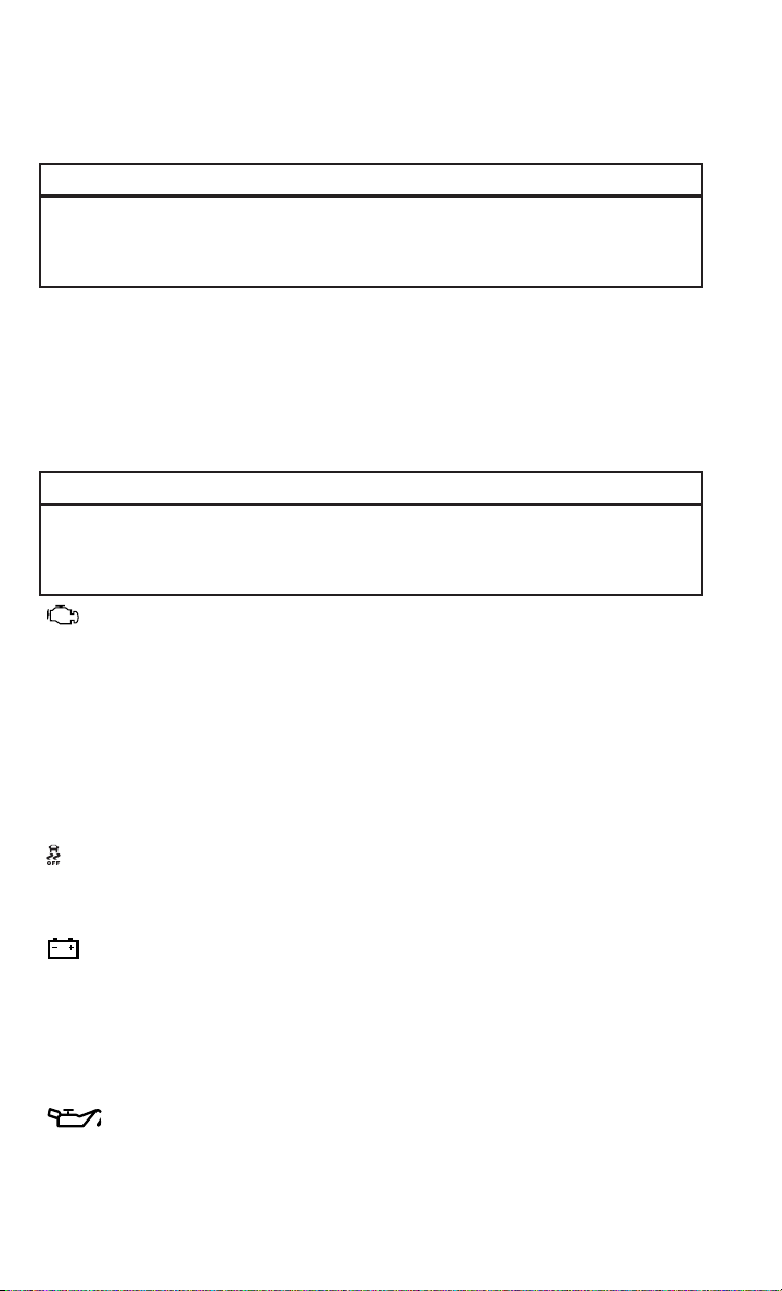
WARNING!
A hot engine cooling system is dangerous. You or others could be badly burned by
steam or boiling coolant. You may want to call an authorized dealer for service if
your vehicle overheats.
BRAKE
- Brake Warning Light
• The Brake Warning light illuminates when there is either a system malfunction or
the parking brake is applied. If the light is on and the parking brake is not applied,
it indicates a possible brake hydraulic malfunction, brake booster problem or an
Anti-Lock Brake System problem.
• Please have your vehicle serviced immediately.
WARNING!
Driving a vehicle with the red brake light on is dangerous. Part of the brake system
may have failed. It will take longer to stop the vehicle. You could have a collision.
Have the vehicle checked immediately.
- Malfunction Indicator Light (MIL)
• Certain conditions, such as a loose or missing gas cap, poor fuel quality, etc., may
illuminate the MIL after engine start. The vehicle should be serviced if the light
stays on through several typical driving cycles. In most situations, the vehicle will
drive normally and not require towing.
• If the MIL flashes when the engine is running, serious conditions may exist that
could lead to immediate loss of power or severe catalytic converter damage. We
recommend you do not operate the vehicle. Have the vehicle serviced
immediately.
- Electronic Stability Control (ESC) OFF Indicator Light
• If the ESC OFF indicator light comes on when the Electronic Stability Control
(ESC) is off.
- Charging System Light
• This light shows the status of the electrical charging system. If the charging
system light remains on, it means that the vehicle is experiencing a problem with
the charging system.
• We recommend you do not continue driving if the charging system light is on. Have
the vehicle serviced immediately.
- Oil Pressure Warning Light
• This light indicates low engine oil pressure. If the light turns on while driving, stop
the vehicle and shut off the engine as soon as possible. A chime will sound for four
minutes when this light turns on.
WHAT TO DO IN EMERGENCIES
138

• We recommend you do not operate the vehicle or engine damage will occur. Have
the vehicle serviced immediately.
- Anti-Lock Brake (ABS) Light
• This light monitors the Anti-Lock Brake System (ABS).
• If the light is not on during starting, stays on, or turns on while driving, we
recommend you drive to the nearest service center and have the vehicle serviced
immediately.
- Electronic Throttle Control (ETC) Light
• This light informs you of a problem with the Electronic Throttle Control (ETC)
system.
• If a problem is detected, the light will come on while the engine is running. Cycle
the ignition when the vehicle has completely stopped and the shift lever is placed
in the PARK position; the light should turn off.
• If the light remains lit with the engine running, your vehicle will usually be
drivable; however, see an authorized service center immediately. If the light is
flashing when the engine is running, immediate service is required and you may
experience reduced performance, an elevated/rough idle or engine stall and your
vehicle may require towing.
- Air Bag Warning Light
• If the light is not on during starting, stays on, or turns on while driving, have the
vehicle serviced by an authorized service center immediately.
- SERV (Service) 4WD Indicator Light
• The SERV 4WD light monitors the electric shift four-wheel drive system. If the
SERV 4WD light stays on or comes on during driving, it means that the four-wheel
drive system is not functioning properly and that service is required.
• For vehicles equipped with a premium cluster this indicator will display in the
Electronic Vehicle Information Center (EVIC).
- Transmission Temperature Warning Light
• This light indicates that there is excessive transmission fluid temperature that
might occur with severe usage such as trailer towing. If this light turns on, stop the
vehicle and run the engine at idle, with the transmission in NEUTRAL, until the
light turns off. Once the light turns off, you may continue to drive normally.
OIL CHANGE EVIC INDICATOR
Message
• If an “oil change” message (shown as "Change Oil Soon" and "Oil Change
Needed") appears and a single chime sounds, it is time for your next required oil
change.
WHAT TO DO IN EMERGENCIES
139

Resetting The Light After Servicing
• Turn the ignition switch to the ON/RUN position (do not start engine).
• Fully depress the accelerator pedal three times within 10 seconds.
• Turn the ignition switch to the OFF/LOCK position.
- Low Coolant Level Indicator Light
• This light indicates low coolant level. If the light turns on while driving, stop the
vehicle and shut off the engine as soon as possible.
• We recommend you do not operate the vehicle or engine damage will occur. Have
the vehicle serviced immediately.
IF YOUR ENGINE OVERHEATS
• In any of the following situations, you can reduce the potential for overheating by
taking the appropriate action.
• On the highways — slow down.
• In city traffic — while stopped, place the transmission in NEUTRAL, but do not
increase engine idle speed.
NOTE:
There are steps that you can take to slow down an impending overheat condition:
• If your air conditioner (A/C) is on, turn it off. The A/C system adds heat to the
engine cooling system and turning the A/C off can help remove this heat.
• You can also turn the temperature control to maximum heat, the mode control to
floor and the blower control to high. This allows the heater core to act as a
supplement to the radiator and aids in removing heat from the engine cooling
system.
CAUTION!
Driving with a hot cooling system could damage your vehicle. If the temperature
gauge reads HOT (H), pull over and stop the vehicle. Idle the vehicle with the air
conditioner turned off until the pointer drops back into the normal range. If the
pointer remains on HOT (H), and you hear continuous chimes, turn the engine off
immediately, and call for service.
WARNING!
You or others can be badly burned by hot engine coolant (antifreeze) or steam from
your radiator. If you see or hear steam coming from under the hood, do not open
the hood until the radiator has had time to cool. Never try to open a cooling system
pressure cap when the radiator or coolant bottle is hot.
WHAT TO DO IN EMERGENCIES
140

JACKING AND TIRE CHANGING
Jack Location
• The jack and jack tools are stored under the front passenger seat.
Removal Of Jack And Tools
• To access the jack and jack tools you must remove the plastic access cover,
located on the side of the seat. To remove the cover, pull the front part of the cover
(closest to the front of the seat) toward you to release a locking tab. Once the front
of the cover is loose, slide the cover toward the front of the seat until it is free from
the seat frame.
1500 Series Trucks
• Remove the jack and tool bag by removing the wing bolt and sliding the jack and
tool bag from under the seat.
WHAT TO DO IN EMERGENCIES
141

2500/3500 Series Trucks
• Remove the jack and tool bracket assembly by removing the wing bolt and sliding
the jack and tool bracket assembly from under the seat.
Removing The Spare Tire
• Remove the spare tire before attempting to jack up the truck. Attach the wheel
wrench to the jack extension tube. Insert the tube through the access hole
between the lower tailgate and the top of the bumper and into the winch
mechanism tube. Rotate the wheel wrench handle counterclockwise until the
spare tire is on the ground with enough cable slack to allow you to pull it out from
under the vehicle. When the spare is clear, tilt the retainer at the end of the cable
and pull it through the center of the wheel.
NOTE:
Always stow the spare tire with the valve stem facing the ground.
1. Wheel Wrench
2. Spare Tire
• It is recommended that you stow the
flat or spare to avoid tangling the loose
cable.
NOTE:
The winch mechanism is designed for
use with the jack extension tube only.
Use of an air wrench or other power tools
is not recommended and can damage the
winch.
WHAT TO DO IN EMERGENCIES
142

Preparations
1. Park the vehicle on a firm, level surface. Avoid ice or slippery areas.
2. Turn on the Hazard Warning flasher.
3. Set the parking brake.
4. Place the shift lever into PARK. On four-wheel drive vehicles, shift the transfer
case to the 4L position.
5. Turn the ignition OFF.
• Block both the front and rear of the wheel diagonally opposite the jacking position.
For example, if the right front wheel is being changed, block the left rear wheel.
NOTE:
Passengers should not remain in the ve-
hicle when the vehicle is being jacked.
Instructions
1. Remove the spare wheel, jack, and
tools from storage.
2. Using the wheel wrench, loosen, but
do not remove, the wheel nuts by
turning them counterclockwise one
turn while the wheel is still on the
ground.
3. Placement of the jack:
WHAT TO DO IN EMERGENCIES
143

1500 Series Trucks
• When changing a front wheel, place the scissors jack under the rear portion of the
lower control arm as shown below.
• Operate the jack using the jack drive tube and the wheel wrench. The tube
extension may be used but is not required.
WHAT TO DO IN EMERGENCIES
144

• For 4x2 and 4x4 trucks, when changing a rear wheel, assemble the jack drive tube
to the jack and connect the drive tube to the extension tube. Place the jack under
the axle between the wheel and the shock bracket with the drive tubes extending
to the rear.
• Connect the jack tube extension and wheel wrench.
WHAT TO DO IN EMERGENCIES
145

2500/3500 Series Trucks
• For 2500/3500 4x2 series trucks, when changing a front wheel, place the bottle
jack under the frame rail behind the wheel. Locate the jack as far forward as
possible on the straight part of the frame.
• Operate the jack using the jack drive tube and the wheel wrench. The tube
extension, may be used, but is not required.
WHAT TO DO IN EMERGENCIES
146

• For 2500/3500 4x4 series trucks, when changing the front wheel, assemble the
jack drive tube to the jack and connect the drive tube to the extension tube. Place
the jack under the axle as close to the tire as possible with the drive tubes
extending to the front. Connect the jack tube extension and wheel wrench.
• For 4x2 and 4x4 trucks, when changing
a rear wheel, assemble the jack drive tube to the jack and connect the drive tube
to the extension tube. Place the jack under the axle between the spring and the
shock absorber with the drive tubes extending to the rear.
• Connect the jack tube extension and wheel wrench.
NOTE:
If the bottle jack will not lower by turning the dial (thumbwheel) by hand, it may be
necessary to use the jack drive tube in order to lower the jack.
• By rotating the wheel wrench clockwise, raise the vehicle until the wheel just
clears the surface.
WHAT TO DO IN EMERGENCIES
147

• Remove the wheel nuts and pull the wheel off. On single rear-wheel (SRW) trucks,
install the spare wheel and wheel nuts with the cone shaped end of the wheel nuts
toward the wheel. On 3500 dual rear-wheel models (DRW) the wheel nuts are a
two-piece assembly with a flat face. Lightly tighten the wheel nuts. To avoid the
risk of forcing the vehicle off the jack, do not fully tighten the wheel nuts until the
vehicle has been lowered.
• Using the lug wrench, finish tightening the wheel nuts using a crisscross pattern.
The correct wheel nut tightness is 130 ft lbs (175 N·m) torque (1500 Series),
135 ft lbs (183 N·m) torque for 2500/3500 single-rear wheel (SRW) models, and
140 ft lbs (190 N·m) for 3500 dual rear-wheel models. If in doubt about the
correct tightness, have them checked with a torque wrench by your authorized
dealer or at a service station.
• Install the wheel center cap and remove the wheel blocks. Do not install chrome
or aluminum wheel center caps on the spare wheel. This may result in cap
damage.
• Lower the jack to its fully closed position. If the bottle jack will not lower by
turning the dial (thumbwheel) by hand, it may be necessary to use the jack drive
tube in order to lower the jack. Stow the replaced tire, jack, and tools as previously
described.
• Adjust the tire pressure when possible.
NOTE:
Do not oil wheel studs. For chrome wheels, do not substitute with chrome plated
wheel nuts.
WHAT TO DO IN EMERGENCIES
148

Reinstalling The Jack And Tools
1500 Series Trucks
1. Tighten the jack all the way down by turning the jack turn-screw clockwise until
the jack is snug.
2. Position the jack and tool bag. Make sure the lug wrench is under the jack near the
jack turn-screw.
3. Secure the tool bag straps to the jack.
4. Place the jack and tools in the storage position holding the jack by the jack
turn-screw, slip the jack and tools under the seat so that the bottom slot engages
into the fastener on the floor.
NOTE:
Ensure that the jack slides into the
front hold down location.
WHAT TO DO IN EMERGENCIES
149

5. Turn the wing bolt clockwise to secure to the floor pan. Reinstall the plastic cover.
2500/3500 Series Trucks
1. Tighten the jack all the way down by turning the jack turn-screw clockwise until
the jack is snug.
2. Position the jack and tools into bracket assembly. Make sure the lug wrench is
under the jack near the jack turn-screw. Snap tools into bracket assembly clips.
Install the jack into bracket assembly and turn screw until jack is snug into
bracket assembly.
3. Place the jack and tool bracket assembly in the storage position holding the jack
by the jack turn-screw, slip the jack and tools under the seat so that the bottom
slot engages into the fastener on the floor.
NOTE:
Ensure that the jack and tool bracket
assembly slides into the front hold down
location.
4. Turn the wing bolt clockwise to secure
to the floor pan. Reinstall the plastic
cover.
WHAT TO DO IN EMERGENCIES
150

Hub Caps/Wheel Covers
• The hub caps must be removed before raising the vehicle off the ground.
• For single rear-wheel (SRW) models, use the blade on the end of the lug wrench
to pry the hub cap off. Insert the blade end into the pry-off notch and carefully pop
off the hub cap with a back-and-forth motion.
• On models with dual rear wheels (DRW), you must first remove the hub caps. The
jack handle driver has a hook at one end that will fit in the pry off notch of the rear
hub caps. Position the hook and pull out on the ratchet firmly. The hub cap should
pop off. The wheel skins can now be removed. For the front hub cap use the blade
on the end of the lug wrench to pry the caps off. The wheel skin can now be
removed.
• You must use the flat end of the lug wrench to pry off the wheel skins. Insert the
flat tip completely and using a back-and-forth motion, loosen the wheel skin.
Repeat this procedure around the tire until the skin pops off.
• Replace the wheel skins first using a rubber mallet. When replacing the hub caps,
tilt the cap retainer over the lug nut bolt circle and strike the high side down with
a rubber mallet. Be sure that the hub caps and wheel skins are firmly seated
around the wheel.
Wheel Nuts
• All wheel nuts should be tightened occasionally to eliminate the possibility of
wheel studs being sheared or the bolt holes in the wheels becoming elongated.
This is especially important during the first few hundred miles/kilometers of
operation to allow the wheel nuts to become properly set. All wheel nuts should
first be firmly seated against the wheel. The wheel nuts should then be tightened
to recommended torque. Tighten the wheel nuts to final torque in increments.
Progress around the bolt circle, tightening the wheel nut opposite to the wheel nut
just previously tightened until final torque is achieved. Recommended torques are
shown in the following chart.
Disc Wheels
Nut Type Stud Size Hex Size Torque Ft Lbs Torque
Newton Meters
Cone M14 x 1.5 22 mm 120-140 160-190
Flanged M14 x 1.5 22 mm 130-160 175-215
WHAT TO DO IN EMERGENCIES
151

8-Stud — Dual Rear Wheels
• Dual wheels are flat-mounted and center-piloted. The lug nuts are a two-piece
assembly. When the tires are being rotated or replaced, clean these lug nuts and
add two drops of oil at the interface between the hex and the washer.
• Slots in the wheels will assist in prop-
erly orienting the inner and outer
wheels. Align these slots when assem-
bling the wheels for best access to the
tire valve on the inner wheel. The tires
of both dual wheels must be com-
pletely off the ground when tighten-
ing, to ensure wheel centering and
maximum wheel clamping.
• Dual wheel models require a special
heavy-duty lug nut tightening adapter
(included with the vehicle) to correctly
tighten the lug nuts. Also, when it is necessary to remove and install dual rear
wheels, use a proper vehicle lifting device.
NOTE:
When installing a spare tire as part of a dual rear wheel end combination, the tire
diameter of the two individual tires must be compared. If there is a significant
difference, the larger tire should be installed in a front location. The correct direction
of rotation for dual tire installations must also be observed.
These dual rear wheels should be tightened as follows:
1. Tighten the wheel nuts in the num-
bered sequence to a snug fit.
2. Retighten the wheel nuts in the same
sequence to the torques listed in the
table. Go through the sequence a sec-
ond time to verify that specific torque
has been achieved. Retighten to
specifications at 100 miles (160 km)
and after 500 miles (800 km).
• It is recommended that wheel stud
nuts be kept torqued to specifications
at all times. Torque wheel stud nuts to specifications at each lubrication interval.
WHAT TO DO IN EMERGENCIES
152

To Stow The Flat Or Spare
NOTE:
RAM 1500 vehicles equipped with aluminum wheels cannot be stored under the
vehicle because the wheel retainer will not fit through the wheel pilot hole. Secure
the flat tire in the bed of the truck. Have the flat tire repaired or replaced
immediately.
• Turn the wheel so that the valve stem is down. Slide the wheel retainer through the
center of the wheel and position it properly across the wheel opening.
• For convenience in checking the spare tire inflation, stow with the valve stem
toward the rear of the vehicle.
• Attach the wheel wrench to the extension tube. Rotate the winch mechanism until
the wheel is drawn into place against the underside of the vehicle. Continue to
rotate until you feel the winch mechanism slip, or click three or four times. It
cannot be overtightened. Push against the tire several times to be sure it is firmly
in place.
CAUTION!
• Do not attempt to raise the vehicle by jacking on locations other than those
indicated in the Jacking Instructions for this vehicle.
• Before raising the wheel off the ground, make sure that the jack will not damage
surrounding truck parts and adjust the jack position as required.
• Use a back and forth motion to remove the hub cap. Do not use a twisting motion
when removing the hub cap, damage to the hub cap; finish may occur.
• The rear hub caps on the dual rear wheel has two pry off notches. Make sure that
the hook of the jack handle driver is located squarely in the cap notch before
attempting to pull off.
WHAT TO DO IN EMERGENCIES
153

WARNING!
• Do not attempt to change a tire on the side of the vehicle close to moving traffic.
Pull far enough off the road to avoid the danger of being hit when operating the
jack or changing the wheel.
• Being under a jacked-up vehicle is dangerous. The vehicle could slip off the jack
and fall on you. You could be crushed. Never put any part of your body under a
vehicle that is on a jack.
• Never start or run the engine while the vehicle is on a jack. If you need to get
under a raised vehicle, take it to an authorized dealer where it can be raised on
a lift.
• The jack is designed to be used as a tool for changing tires only. The jack should
not be used to lift the vehicle for service purposes. The vehicle should be jacked
on a firm level surface only. Avoid ice or slippery areas.
• Do not attempt to change a tire on the side of the vehicle close to moving traffic,
pull far enough off the road to avoid the danger of being hit when operating the
jack or changing the wheel.
• Carefully follow these tire changing warnings to help prevent personal injury or
damage to your vehicle:
• Always park on a firm, level surface as far from the edge of the roadway as
possible before raising the vehicle.
• Turn on the Hazard Warning flashers.
• Block the wheel diagonally opposite the wheel to be raised.
• Set the parking brake firmly and set an automatic transmission in PARK; a
manual transmission in REVERSE.
• Do not let anyone sit in the vehicle when it is on a jack.
• Do not get under the vehicle when it is on a jack.
• Only use the jack in the positions indicated and for lifting this vehicle during a
tire change.
• If working on or near a roadway, be extremely careful of motor traffic.
• To assure that spare tires, flat or inflated, are securely stowed, spares must be
stowed with the valve stem facing the ground.
• Raising the vehicle higher than necessary can make the vehicle less stable. It
could slip off the jack and hurt someone near it. Raise the vehicle only enough
to remove the tire.
• To avoid the risk of forcing the vehicle off the jack, do not fully tighten the wheel
bolts until the vehicle has been lowered. Failure to follow this warning may
result in personal injury.
• To avoid possible personal injury, handle the wheel covers with care to avoid
contact with any sharp edges.
• A loose tire or jack thrown forward in a collision or hard stop could endanger the
occupants of the vehicle. Always stow the jack parts and the spare tire in the
places provided.
• A loose tire thrown forward in a collision or hard stop could injure the occupants
in the vehicle. Have the deflated (flat) tire repaired or replaced immediately.
WHAT TO DO IN EMERGENCIES
154

JUMP-STARTING
• If your vehicle has a discharged bat-
tery it can be jump-started using a set
of jumper cables and a battery in an-
other vehicle or by using a portable
battery booster pack.
• Jump-starting can be dangerous if
done improperly so please follow the
procedures in this section carefully.
NOTE:
When using a portable battery booster
pack follow the manufacturer’s operating
instructions and precautions.
Preparations for Jump-Start
• The battery in your vehicle is located
in the front of the engine compartment, behind the left headlight assembly.
NOTE:
The positive battery post is covered with a protective cap. Lift up on the cap to gain
access to the positive battery post.
• Set the parking brake, shift the automatic transmission into PARK and turn the
ignition to OFF.
• Turn off the heater, radio, and all unnecessary electrical accessories.
• If using another vehicle to jump-start the battery, park the vehicle within the
jumper cables reach, set the parking brake and make sure the ignition is OFF.
Jump-Starting Procedure
• Connect the positive (+) end of the jumper cable to the positive (+) post of the
discharged vehicle.
• Connect the opposite end of the positive (+) jumper cable to the positive (+) post
of the booster battery.
• Connect the negative end (-) of the jumper cable to the negative (-) post of the
booster battery.
• Connect the opposite end of the negative (-) jumper cable to a good engine ground
(exposed metal part of the discharged vehicle’s engine) away from the battery and
the fuel injection system.
• Start the engine in the vehicle that has the booster battery, let the engine idle a
few minutes, and then start the engine in the vehicle with the discharged battery.
WHAT TO DO IN EMERGENCIES
155

Once the engine is started, remove the jumper cables in the reverse sequence:
• Disconnect the negative (-) jumper cable from the engine ground of the vehicle
with the discharged battery.
• Disconnect the negative end (-) of the jumper cable from the negative (-) post of
the booster battery.
• Disconnect the opposite end of the positive (+) jumper cable from the positive (+)
post of the booster battery.
• Disconnect the positive (+) end of the jumper cable from the positive (+) post of
the discharged vehicle.
• If frequent jump-starting is required to start your vehicle you should have the
battery and charging system inspected at your authorized dealer.
CAUTION!
• Do not use a portable battery booster pack or any other booster source with a
system voltage greater than 12 Volts or damage to the battery, starter motor,
alternator or electrical system may occur.
• Failure to follow these procedures could result in damage to the charging system
of the booster vehicle or the discharged vehicle.
• Accessories that can be plugged into the vehicle power outlets draw power from
the vehicle’s battery, even when not in use (i.e., cellular phones, etc.). Eventu-
ally, if plugged in long enough, the vehicle’s battery will discharge sufficiently to
degrade battery life and/or prevent the engine from starting.
WHAT TO DO IN EMERGENCIES
156

WARNING!
• When temperatures are below the freezing point, electrolyte in a discharged
battery may freeze. Do not attempt jump-starting because the battery could
rupture or explode and cause personal injury. Battery temperature must be
brought above the freezing point before attempting a jump-start.
• Take care to avoid the radiator cooling fan whenever the hood is raised. It can
start anytime the ignition switch is on. You can be injured by moving fan blades.
• Remove any metal jewelry, such as watch bands or bracelets, that might make
an inadvertent electrical contact. You could be severely injured.
• Batteries contain sulfuric acid that can burn your skin or eyes and generate
hydrogen gas which is flammable and explosive. Keep open flames or sparks
away from the battery.
• Do not allow vehicles to touch each other as this could establish a ground
connection and personal injury could result.
• Failure to follow this procedure could result in personal injury or property
damage due to battery explosion.
• Do not connect the cable to the negative post (-) of the discharged battery. The
resulting electrical spark could cause the battery to explode and could result in
personal injury.
EMERGENCY TOW HOOKS
• If your vehicle is equipped with tow hooks, they are mounted in the front.
• For off-road recovery, it is recommended to use both of the front tow hooks to
minimize the risk of damage to the vehicle.
CAUTION!
Tow hooks are for emergency use only, to rescue a vehicle stranded off-road. Do not
use tow hooks for tow truck hookup or highway towing. You could damage your
vehicle. Tow straps are recommended when towing the vehicle; chains may cause
vehicle damage.
WARNING!
• Chains are not recommended for freeing a stuck vehicle. Chains may break,
causing serious injury or death.
• Stand clear of vehicles when pulling with tow hooks. Tow straps and chains may
break, causing serious injury.
WHAT TO DO IN EMERGENCIES
157

SHIFT LEVER OVERRIDE
• If a malfunction occurs and the shift lever cannot be moved out of the PARK
position, you can use the following procedure to temporarily move the shift lever.
• Have your vehicle inspected by your local authorized dealer immediately if the
shift lever override has been used.
Column Shifter
• Tilt the steering wheel to the full up
position and firmly set the parking
brake.
• Turn the Key Fob to the ACC or ON/
RUN position without starting the en-
gine.
• Press and maintain firm pressure on
the brake pedal.
• Using a screwdriver, press and hold
the override tab through the access
port (ringed circle) on the bottom of
the steering column.
• Move the shift lever into the NEUTRAL
position and start the vehicle.
• Release the parking brake.
Center Console Shifter
• Firmly set the parking brake.
•
Turn the Key Fob to the ACC or ON/RUN
position without starting the engine.
• Press and maintain firm pressure on
the brake pedal.
• Using a screwdriver, press and hold
the override tab through the access
port on the center console.
• Move the shift lever into the NEUTRAL
position and start the vehicle.
• Release the parking brake.
WHAT TO DO IN EMERGENCIES
158

MANUAL PARK RELEASE — EIGHT SPEED TRANSMISSION
• In order to push or tow the vehicle in cases where the transmission will not shift
out of PARK (such as a dead battery), a Manual Park Release is available.
• Follow these steps to use the Manual Park Release:
• Firmly apply the parking brake.
• Using a small screwdriver or similar tool, remove the Manual Park Release
access cover, which is just above the parking brake release handle, below and
to the left of the steering column.
• Using the screwdriver or similar tool, push the Manual Park Release lever
locking tab (just below the middle of the lever) to the right.
WHAT TO DO IN EMERGENCIES
159

• While holding the locking tab in the disengaged position, pull the tether strap
to rotate the lever rearward, until it locks in place pointing towards the driver's
seat. Release the locking tab and verify that the Manual Park Release lever is
locked in the released position.
• The vehicle is now out of PARK and
can be towed. Release the parking
brake only when the vehicle is se-
curely connected to a tow vehicle.
To Reset The Manual Park Release:
• Push the locking tab to the right, to unlock the lever.
• Rotate the Manual Park Release lever forward to its original position, until the
locking tab snaps into place to secure the lever.
• Pull gently on the tether strap to confirm that the lever is locked in its stowed
position.
• Re-install the access cover.
WARNING!
Always secure your vehicle by fully applying the parking brake, before activating
the Manual Park Release. Activating the Manual Park Release will allow your
vehicle to roll away if it is not secured by the parking brake or by proper connection
to a tow vehicle. Activating the Manual Park Release on an unsecured vehicle
could lead to serious injury or death for those in or around the vehicle.
WHAT TO DO IN EMERGENCIES
160

TOWING A DISABLED VEHICLE
Towing Condition Wheels OFF the Ground 2WD Models 4WD Models
Flat Tow NONE
If transmission is operable:
•
Transmission in NEUTRAL
• 30 mph (48 km/h) max
• 15 miles (24 km) max distance
•
Auto Transmission in PARK
• Manual Transmission in gear
(NOT NEUTRAL)
• Transfer Case in NEUTRAL
•TowinFORWARD direction
Wheel Lift or Dolly Tow
Front
NOT ALLOWED
Rear
OK NOT ALLOWED
Flatbed
ALL BEST METHOD BEST METHOD
WHAT TO DO IN EMERGENCIES
161

FREEING A STUCK VEHICLE
• If your vehicle becomes stuck in mud, sand or snow, it can often be moved by a
rocking motion. Turn your steering wheel right and left to clear the area around the
front wheels. Then, move the shift lever back and forth between REVERSE and
DRIVE. Using minimal accelerator pedal pressure to maintain the rocking motion,
without spinning the wheels, is most effective.
• Allow the engine to idle with the transmission shift lever in NEUTRAL for at least
one minute after every five rocking-motion cycles. This will minimize overheating
and reduce the risk of transmission failure during prolonged efforts to free a stuck
vehicle.
NOTE:
If your vehicle is equipped with Electronic Stability Control (ESC) then press the
"ESC Off" switch, to place the Electronic Stability Control (ESC) system in "Partial
Off" mode, before rocking the vehicle.
CAUTION!
Revving the engine or spinning the wheels too fast may lead to transmission
overheating and failure. It can also damage the tires. Do not spin the wheels above
30 mph (48 km/h) while in gear (no transmission shifting occurring).
WARNING!
Fast spinning tires can be dangerous. Forces generated by excessive wheel speeds
may cause tire damage or failure. A tire could explode and injure someone. Do not
spin your vehicle's wheels faster than 30 mph (48 km/h) when you are stuck. Do
not let anyone near a spinning wheel, no matter what the speed.
WHAT TO DO IN EMERGENCIES
162

EVENT DATA RECORDER (EDR)
• This vehicle is equipped with an Event Data Recorder (EDR). The main purpose of
an EDR is to record, in certain crash or near crash-like situations, such as an air
bag deployment or hitting a road obstacle, data that will assist in understanding
how a vehicle’s systems performed. The EDR is designed to record data related to
vehicle dynamics and safety systems for a short period of time, typically 30 sec-
onds or less. The EDR in this vehicle is designed to record such data as:
• How various systems in your vehicle were operating.
• Whether or not the driver and passenger safety belts were buckled/fastened.
• How far (if at all) the driver was depressing the accelerator and/or brake pedal.
• How fast the vehicle was traveling.
• These data can help provide a better understanding of the circumstances in which
crashes and injuries occur.
NOTE:
EDR data are recorded by your vehicle only if a non-trivial crash situation occurs; no
data are recorded by the EDR under normal driving conditions and no personal data
(e.g. name, gender, age, and crash location) are recorded. However, other parties,
such as law enforcement, could combine the EDR data with the type of personally
identifying data routinely acquired during a crash investigation.
• To read data recorded by an EDR, special equipment is required, and access to the
vehicle or the EDR is needed. In addition to the vehicle manufacturer, other
parties such as law enforcement, that have the special equipment, can read the
information if they have access to the vehicle or the EDR.
WHAT TO DO IN EMERGENCIES
163
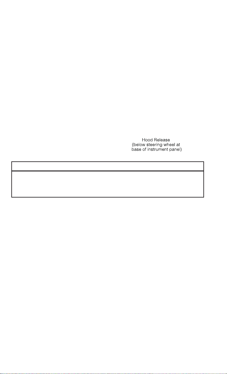
OPENING THE HOOD
• Pull the hood release lever located
below the steering wheel at the base of
the instrument panel.
• Reach into the opening beneath the
center of the hood and move the safety
latch lever while lifting the hood at the
same time.
WARNING!
Be sure the hood is fully latched before driving your vehicle. If the hood is not fully
latched, it could open when the vehicle is in motion and block your vision. Failure
to follow this warning could result in serious injury or death.
MAINTAINING YOUR VEHICLE
164

ENGINE COMPARTMENT
3.6L Engine
MAINTAINING YOUR VEHICLE
165
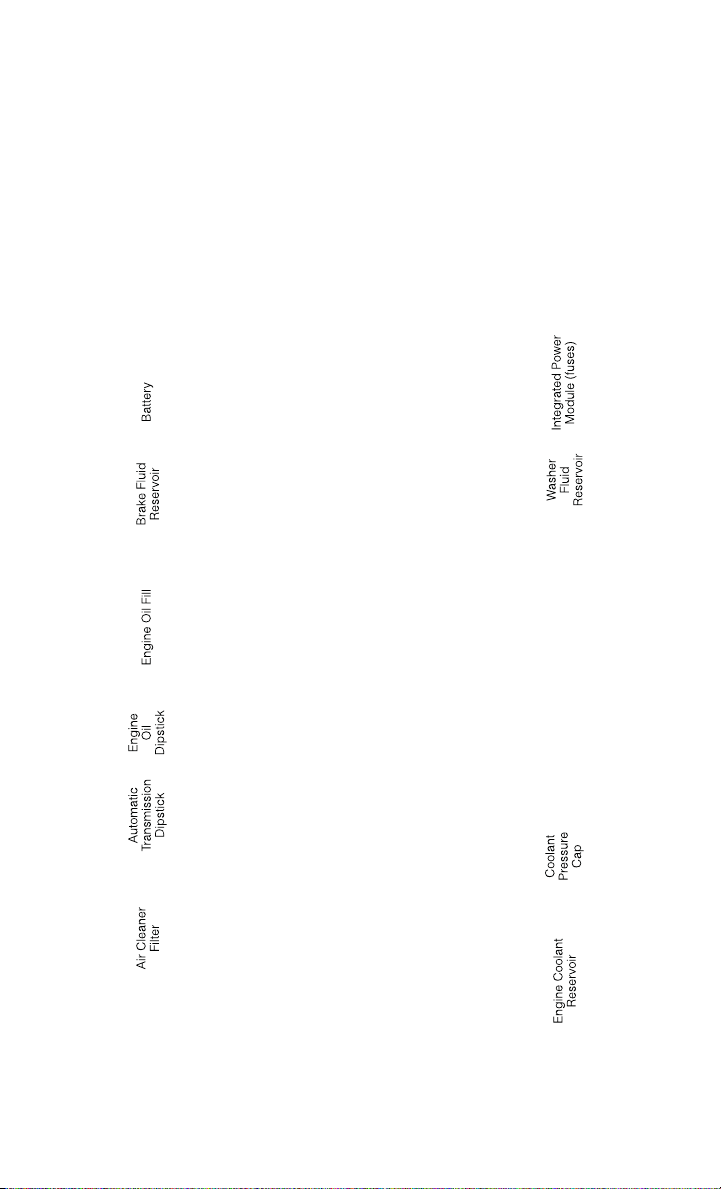
4.7L Engine
MAINTAINING YOUR VEHICLE
166
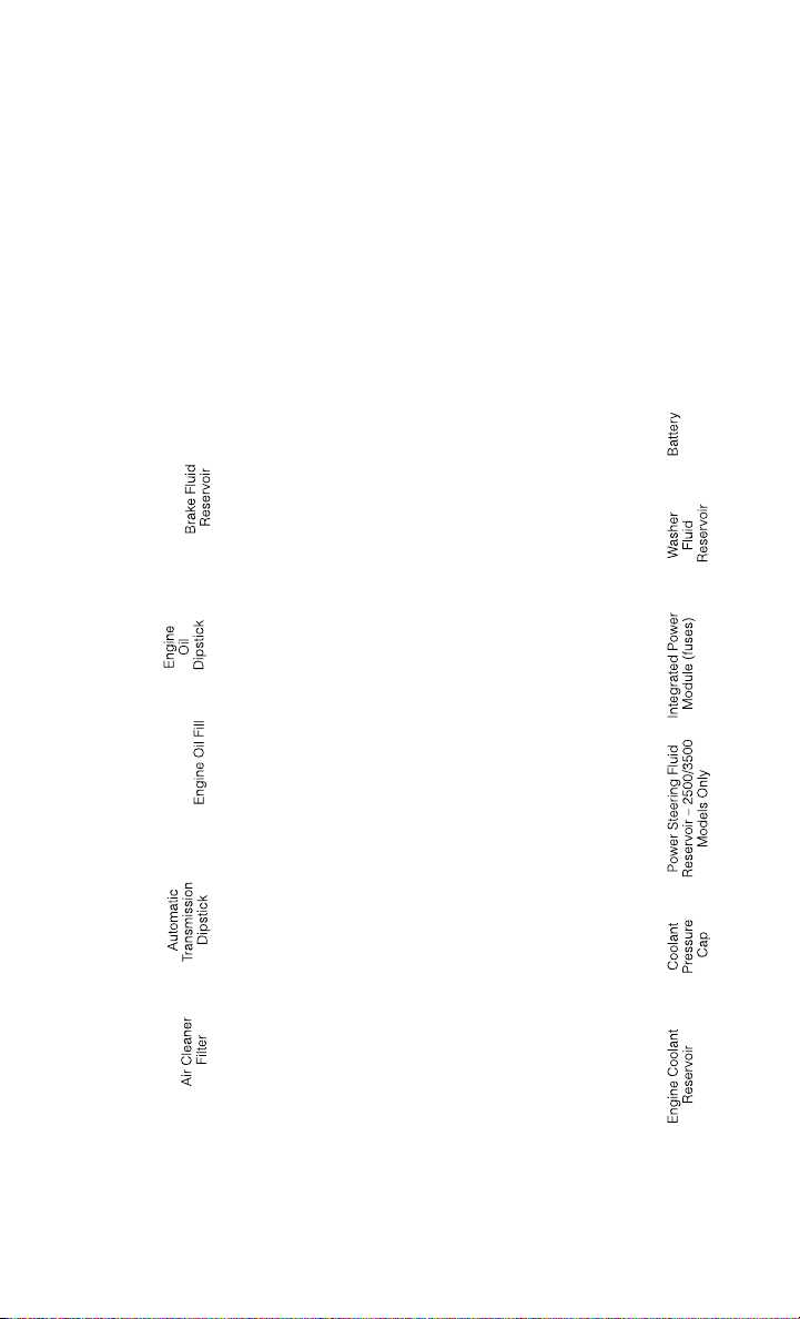
5.7L ENGINE
MAINTAINING YOUR VEHICLE
167

6.7L DIESEL ENGINE – 2500/3500 68RFE TRANSMISSION – IF EQUIPPED
MAINTAINING YOUR VEHICLE
168
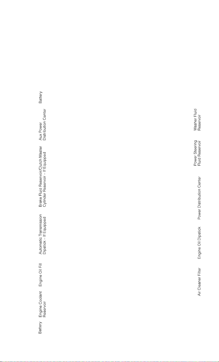
6.7L DIESEL ENGINE – 3500 AS68RC HD TRANSMISSION – IF EQUIPPED
MAINTAINING YOUR VEHICLE
169

FLUIDS AND CAPACITIES
Gasoline Versions
Component Fluid, Lubricant, or Genuine Part Capacities
Engine Coolant
3.6L, 4.7L Engine
We recommend you use MOPAR
®
Antifreeze/
Coolant 10 Year/150,000 Mile Formula OAT
(Organic Additive Technology).
14 Quarts (13 Li-
ters)
Engine Coolant
5.7L 1500 Mod-
els
We recommend you use MOPAR
®
Antifreeze/
Coolant 10 Year/150,000 Mile Formula OAT
(Organic Additive Technology).
16 Quarts (15 Li-
ters)
Engine Coolant
5.7L 2500/
3500 Models
We recommend you use MOPAR
®
Antifreeze/
Coolant 10 Year/150,000 Mile Formula OAT
(Organic Additive Technology) .
18.7 Quarts
(17.7 Liters)
Engine Coolant
5.7L 2500/
3500 Models
w/Heavy Duty
We recommend you use MOPAR
®
Antifreeze/
Coolant 10 Year/150,000 Mile Formula OAT
(Organic Additive Technology) .
19.2 Quarts
(18.2 Liters)
Engine Oil with
Filter 3.6L, 4.7L,
5.7L
We recommend you use API certified 5W-
20 engine oil, meeting the requirements of
FCA US Material Standard MS-6395. Refer
to you oil filler cap for correct SAE grade.
3.6L Engine -
6 Quarts (5.7 Li-
ters)
4.7L Engine -
6 Quarts (5.7 Li-
ters)
5.7L Engine -
7 Quarts (6.6 Li-
ters)
Engine Oil with
Filter 5.7L
For 2500/
3500 trucks oper-
ating with a gross
combined weight
rating greater than
14,000 lbs/
(6,350 kg)
We recommend you use API Certified SAE
5W-30 engine oil, meeting the requirements
of FCA US Material Standard MS-6395. Re-
fer to your engine oil filter cap for correct
SAE grade.
5.7L Engine -
7 Quarts (6.6 Li-
ters)
Engine Oil Filter
3.6L, 4.7L, 5.7L
We recommend you use MOPAR
®
Engine Oil
Filters.
—
Spark Plug 3.6L
We recommend you use MOPAR
®
Spark
Plugs.
—
Spark Plug 4.7L
We recommend you use MOPAR
®
Spark
Plugs.
—
Spark Plug 5.7L
We recommend you use MOPAR
®
Spark
Plugs.
—
Automatic Trans-
mission — Eight-
Speed Automatic
We recommend you use Mopar
®
ZF
8&9 Speed ATF™ Automatic Transmission
Fluid.
—
MAINTAINING YOUR VEHICLE
170

Component Fluid, Lubricant, or Genuine Part Capacities
Automatic Trans-
mission — Six-
Speed Automatic
with Gasoline En-
gine
We recommend you use MOPAR
®
ATF+4 Au-
tomatic Transmission Fluid.
—
Manual Transmis-
sion G-56
We recommend you use MOPAR
®
ATF+4 Au-
tomatic Transmission Fluid.
—
Transfer Case
We recommend you use MOPAR
®
BW44–
44 Transfer Case Fluid.
—
Front Axle
1500 Four-Wheel
Drive Models
We recommend you use GL-5 SAE 75W-
90 MS-9763.
—
Rear Axle
1500 Models
We recommend you use MOPAR
®
Synthetic
Gear Lubricant SAE 75W-140 MS-8985.
Limited-Slip Rear Axles require the addition
of 118 ml (4 oz) of MOPAR
®
Limited Slip
Additive MS-10111.
—
Front and Rear
Axle 2500/
3500 Models
We recommend you use Synthetic, GL-
5 SAE 75W-90. Limited-Slip 10.5/
11.5 inch Rear Axles Limited slip additive is
not required.
—
Brake Master Cyl-
inder
We recommend you use MOPAR
®
DOT 3 and
SAE J1703. If DOT 3 is not available, then
DOT 4 is acceptable.
—
Power Steering
Reservoir
We recommend you use MOPAR
®
Power
Steering Fluid +4 or MOPAR
®
ATF+4
®
Auto-
matic Transmission Fluid.
—
Fuel Selection
3.6L, 4.7L
87 Octane
1500 Regular Cab
Shortbed/Crew
Quad Cab -
26 Gallons (98 Li-
ters) (Approxi-
mate) 1500 Regu-
lar Cab Longbed/
Crew Quad Cab
(Optional) -
32 Gallons
(121 Liters) (Ap-
proximate) 2500/
3500 Shortbed -
34 Gallons
(129 Liters) (Ap-
proximate) 2500/
3500 Longbed -
35 Gallons
(132 Liters) (Ap-
proximate)
MAINTAINING YOUR VEHICLE
171

Component Fluid, Lubricant, or Genuine Part Capacities
Fuel Selection
5.7L
87 Octane Acceptable. 89 Octane Recom-
mended.
1500 Regular Cab
Shortbed/Crew
Quad Cab -
26 Gallons (98 Li-
ters) (Approxi-
mate) 1500 Regu-
lar Cab Longbed/
Crew Quad Cab
(Optional) -
32 Gallons
(121 Liters) (Ap-
proximate) 2500/
3500 Shortbed -
34 Gallons
(129 Liters) (Ap-
proximate) 2500/
3500 Longbed -
35 Gallons
(132 Liters) (Ap-
proximate)
Diesel Versions
Component Fluid, Lubricant, or Genuine Part Capacities
Engine Coolant
6.7L Turbo Diesel
Engine
We recommend you use MOPAR
®
Antifreeze/
Coolant Ten Year/150,000 Mile Formula OAT
(Organic Additive Technology).
5.7 Gallons
(21.4 Liters)
Engine Oil with
Filter 6.7L Turbo
Diesel Engine
In ambient temperatures below 0°F (-18°C),
We recommend you use 5W-40 synthetic
engine oil that meets FCA US Material Stan-
dard MS-10902 and the API CJ-4 engine oil
category is required. In ambient tempera-
tures above 0°F (-18°C), We recommend you
use 15W-40 engine oil that meets FCA US
Material Standard MS-10902 and the API
CJ-4 engine oil category is required.
12 Quarts
(11.4 Liters)
MAINTAINING YOUR VEHICLE
172

Component Fluid, Lubricant, or Genuine Part Capacities
Fuel Selection
6.7L Turbo Diesel
Use good quality diesel fuel from a repu-
table supplier in your vehicle. Federal law
requires that you must fuel this vehicle with
Ultra Low Sulfur Highway Diesel fuel
(15 ppm Sulfur maximum) and prohibits the
use of Low Sulfur Highway Diesel fuel
(500 ppm Sulfur maximum) to avoid dam-
age to the emissions control system. For
most year-round service, No. 2 diesel fuel
meeting ASTM specification D-975 Grade
S15 will provide good performance. If the
vehicle is exposed to extreme cold (below
20°F or -7°C), or is required to operate at
colder-than-normal conditions for prolonged
periods, use climatized No. 2 diesel fuel or
dilute the No. 2 diesel fuel with 50% No.
1 diesel fuel. This will provide better protec-
tion from fuel gelling or wax-plugging of the
fuel filters. This vehicle is fully compatible
with biodiesel blends up to 5% biodiesel
meeting ASTM specification D-975.
Standard Rear
Tank - 52 Gallons
(197 Liters)
Optional Midship
Tank - 22 Gallons
(83 Liters)
Engine Oil Filter
6.7L Engine
We recommend you use MOPAR
®
Engine Oil
Filters.
—
Engine Fuel Filter
6.7L Turbo Diesel
We recommend you use MOPAR
®
Fuel Filter.
Must meet 5 micron rating. Using a fuel fil-
ter that does not meet the manufacturer's
filtration and water separating requirements
can severely impact fuel system life and reli-
ability.
—
Crankcase Ventila-
tion Filter 6.7L
Turbo Diesel
We recommend you use MOPAR
®
CCV Filter. —
Automatic Trans-
mission (5-Speed
545RFE)
MOPAR
®
ATF+4
®
Automatic Transmission
Fluid or equivalent licensed ATF+4
®
prod-
uct.
—
Automatic Trans-
mission (6-Speed
AS68RC)
MOPAR
®
AS68RC Automatic Transmission
Fluid or equivalent.
Clutch Linkage
We recommend you use MOPAR
®
Multi-
Purpose Grease, NLGI Grade 2 E.P.
—
Manual Transmis-
sion G-56
We recommend you use MOPAR
®
ATF+4
®
Automatic Transmission Fluid.
—
Transfer Case
We recommend you use MOPAR
®
BW44–
44 Transfer Case Fluid.
—
Front and Rear
Axle
We recommend you use Synthetic, GL-
5 SAE, 75W-90 Synthetic (MS-9763) .
—
MAINTAINING YOUR VEHICLE
173

Component Fluid, Lubricant, or Genuine Part Capacities
Brake Master Cyl-
inder
We recommend you use MOPAR
®
DOT 3. If
DOT 3 is not available, then DOT 4 is ac-
ceptable. Use only recommended Brake Flu-
ids.
—
Power Steering
Reservoir
We recommend you use MOPAR
®
Power
Steering Fluid +4 or MOPAR
®
ATF+4
®
Auto-
matic Transmission Fluid.
—
Diesel Exhaust
Fluid Tank (Ap-
proximate)
We recommend you use MOPAR
®
Diesel Ex-
haust Fluid (API Certified) (DEF) or equiva-
lent that has been API Certified to the ISO
22241 standard. Use of fluids not API Certi-
fied to ISO 22241 may result in system
damage.
5.5 Gallons
(21 Liters)
CAUTION!
• Mixing of engine coolant (antifreeze) other than specified Organic Additive
Technology (OAT) engine coolant (antifreeze), may result in engine damage and
may decrease corrosion protection. Organic Additive Technology (OAT) engine
coolant is different and should not be mixed with Hybrid Organic Additive
Technology (HOAT) engine coolant (antifreeze) or any “globally compatible”
coolant (antifreeze). If a non-OAT engine coolant (antifreeze) is introduced into
the cooling system in an emergency, the cooling system will need to be drained,
flushed, and refilled with fresh OAT coolant (conforming to MS-12106), by an
authorized dealer as soon as possible.
• Do not use water alone or alcohol-based engine coolant (antifreeze) products. Do
not use additional rust inhibitors or antirust products, as they may not be
compatible with the radiator engine coolant and may plug the radiator.
• This vehicle has not been designed for use with propylene glycol-based engine
coolant (antifreeze). Use of propylene glycol-based engine coolant (antifreeze)
is not recommended.
E-85 Flexible Fuel – 3.6L/4.7L Engine Only
CAUTION!
Only vehicles with the E-85 fuel filler door label or a yellow gas cap can operate on
E-85.
Refer to your Owner's Manual on the DVD for further details.
MAINTAINING YOUR VEHICLE
174

MAINTENANCE SCHEDULE – GASOLINE ENGINE
Your vehicle is equipped with an automatic oil change indicator system. The oil
change indicator system will remind you that it is time to take your vehicle in for
scheduled maintenance.
Based on engine operation conditions, the oil change indicator message will
illuminate. This means that service is required for your vehicle. Operating conditions
such as frequent short-trips, trailer tow, extremely hot or cold ambient temperatures,
and E85 fuel usage will influence when the “Oil Change Required” message is
displayed. Severe Operating Conditions can cause the change oil message to
illuminate as early as 3,500 miles (5,600 km) since last reset. Have your vehicle
serviced as soon as possible, within the next 500 miles (805 km).
Your authorized dealer will reset the oil change indicator message after completing
the scheduled oil change. If a scheduled oil change is performed by someone other
than your authorized dealer, the message can be reset by referring to the steps
described under “Electronic Vehicle Information Center (EVIC)/Oil Change Re-
quired” in “Understanding Your Instrument Panel” for further information.
NOTE:
Under no circumstances should oil change intervals exceed 10,000 miles
(16,000 km) or twelve months, whichever comes first.
Once A Month Or Before A Long Trip:
• Check engine oil level
• Check windshield washer fluid level
• Check the tire inflation pressures and look for unusual wear or damage
• Check the fluid levels of the coolant reservoir, brake master cylinder, power
steering (2500/3500 Models Only) and automatic transmission (six-speed only)
as needed
• Check function of all interior and exterior lights
MAINTAINING YOUR VEHICLE
175

Maintenance Chart – Gasoline Engine
Required Maintenance
Refer to the Maintenance Schedules on the following pages for required mainte-
nance.
At Every Oil Change Interval As Indicated By Oil Change Indicator System:
•
Change oil and filter.
• Rotate the tires. Rotate at the first sign of irregular wear, even if it occurs before the oil
indicator system turns on.
•
Inspect battery and clean and tighten terminals as required.
•
Inspect automatic transmission fluid if equipped with dipstick.
•
Inspect brake pads, shoes, rotors, drums, hoses and park brake.
•
Inspect engine cooling system protection and hoses.
•
Inspect exhaust system.
•
Inspect engine air cleaner if using in dusty or off-road conditions.
•
Lube the front drive shaft fitting (2500/3500 (4x4) models only).
MAINTAINING YOUR VEHICLE
176

Mileage or time passed
(whichever comes first)
20,000
30,000
40,000
50,000
60,000
70,000
80,000
90,000
100,000
110,000
120,000
130,000
140,000
150,000
Or Years: 2 3 4 5 6 7 8 9 10 11 12 13 14 15
Or Kilometers:
32,000
48,000
64,000
80,000
96,000
112,000
128,000
144,000
160,000
176,000
192,000
208,000
224,000
240,000
Additional Inspections
Inspect the CV joints. X X X X X
Inspect front suspension, tie rod ends,
and replace if necessary.
XXX X X X X
Inspect the front and rear axle surfaces.
If gear oil leakage is suspected, check
the fluid level. If using your vehicle for
police, taxi, fleet, off-road or frequent
trailer towing, change axle fluid.
XXX X X X X
Inspect the brake linings, parking brake
function.
XXX X X X X
Inspect transfer case fluid. X X X
Additional Maintenance
Replace engine air filter. X X X X X
Replace spark plugs (3.6L engine).** X
Replace the top row (intake side) of
spark plugs (4.7L Engine).**
XX X X X
Replace the side row (exhaust side) of
spark plugs (4.7L Engine).**
X
Replace spark plugs (5.7L engine).** X X X X X
Replace the ignition cables (4.7L En-
gine).
X
MAINTAINING YOUR VEHICLE
177

Mileage or time passed
(whichever comes first)
20,000
30,000
40,000
50,000
60,000
70,000
80,000
90,000
100,000
110,000
120,000
130,000
140,000
150,000
Or Years: 2 3 4 5 6 7 8 9 10 11 12 13 14 15
Or Kilometers:
32,000
48,000
64,000
80,000
96,000
112,000
128,000
144,000
160,000
176,000
192,000
208,000
224,000
240,000
Flush and replace the engine coolant at
10 years or 150,000 miles
(240,000 km) whichever comes first.
XX
Change automatic transmission fluid and
filter(s), if using your vehicle for police,
taxi, fleet, or frequent trailer towing.
X
Change automatic transmission fluid and
filter.
X
Inspect the transfer case fluid, change
for any of the following: police, taxi,
fleet, or frequent trailer towing.
X
Change the transfer case fluid. X
Inspect and replace PCV valve if neces-
sary.
X
** The spark plug change interval is mileage based only, yearly intervals do not apply.
WARNING!
• You can be badly injured working on or around a motor vehicle. Do only service work for which you have the knowledge and the
right equipment. If you have any doubt about your ability to perform a service job, take your vehicle to a competent mechanic.
• Failure to properly inspect and maintain your vehicle could result in a component malfunction and effect vehicle handling and
performance. This could cause an accident.
MAINTAINING YOUR VEHICLE
178

MAINTENANCE RECORD
Odometer Date Signature, Autho-
rized Service Center
20,000 Miles
(32,000 km) or
2 Years
30,000 Miles
(48,000 km) or
3 Years
40,000 Miles
(64,000 km) or
4 Years
50,000 Miles
(80,000 km) or
5 Years
60,000 Miles
(96,000 km) or
6 Years
70,000 Miles
(112,000 km) or
7 Years
80,000 Miles
(128,000 km) or
8 Years
Odometer Date Signature, Autho-
rized Service Center
90,000 Miles
(144,000 km) or
9 Years
100,000 Miles
(160,000 km) or
10 Years
110,000 Miles
(176,000 km) or
11 Years
120,000 Miles
(192,000 km) or
12 Years
130,000 Miles
(208,000 km) or
13 Years
140,000 Miles
(224,000 km) or
14 Years
150,000 Miles
(240,000 km) or
15 Years
MAINTAINING YOUR VEHICLE
179

MAINTENANCE SCHEDULE — 6.7L CUMMINS DIESEL ENGINE
CAUTION!
Failure to perform the required maintenance items may result in damage to the
vehicle.
At Each Stop For Fuel
Check the engine oil level at least 30 minutes after a fully warmed engine is shut off.
Checking the oil level while the vehicle is on level ground will improve the accuracy
of the oil level reading. Add oil only when the level is at or below the ADD or MIN
mark.
Once A Month
• Inspect the batteries, and clean and tighten the terminals as required.
• Check the fluid levels of the coolant reservoir, brake master cylinder, and
automatic transmission (if equipped), and add as needed.
At Each Oil Change
• Change the engine oil filter.
• Inspect the exhaust system.
• Inspect engine air filter.
• Check the coolant level, hoses, and clamps.
• Lubricate outer tie rod ends.
Inspection and service should also be performed anytime a malfunction is observed
or suspected. Retain all receipts.
Oil Change Indicator System
Your vehicle is equipped with an engine oil change indicator system. This system will
alert you when it is time to change your engine oil by displaying the words “Oil
Change Due” on your Electronic Vehicle Information Center (EVIC). The engine oil
change indicator system is duty cycle based, which means the engine oil change
interval may fluctuate depending on your personal driving style. Driving styles such
as frequent stop and go type driving or extended idle time can increase the frequency
of the engine oil change. This is the result of more frequent regeneration of the
exhaust after treatment system, which can decrease the life of the engine oil. Failure
to change the engine oil per the maintenance schedule can result in internal engine
damage.
For information on resetting the Oil Change Indicator message, refer to “Oil Change
Due” under “Electronic Vehicle Information Center (EVIC)/EVIC Warning Lights” in
“Understanding Your Instrument Panel” for further information.
MAINTAINING YOUR VEHICLE
180

Replace the engine oil and oil filter every 15,000 miles (24 000 km) or six months, or
sooner if prompted by the oil change indicator system. Under no circumstances should oil
change intervals exceed 15,000 miles (24 000 km) or six months, whichever comes first.
NOTE:
• Under no circumstances should oil change intervals exceed 15,000 miles
(24,000 km) or six months or 500 Hours, whichever comes first.
• Replace the engine oil and oil filter every 12,500 miles (20 000 km) when
running B20 fuel (Chassis Cab Only).
If Chassis Cab models are operated with greater than 5% levels of Biodiesel, the oil
change interval must not exceed 12,500 miles (20 000 km) under any circum-
stances. See the Fuel Requirements section for more information regarding opera-
tion of Chassis Cab models configured for use with Biodiesel blend(B6-B20) fuel
meeting ASTM specification D-7467.
Perform Service Indicator
Your vehicle will require emissions maintenance at a set interval. To help remind you
when this maintenance is due, the Electronic Vehicle Information Center (EVIC) will
display “Perform Service”. When the “Perform Service” message is displayed on the
EVIC it is necessary to have the emissions maintenance performed. Emissions
maintenance may include replacing the Closed Crankcase Ventilation (CCV) filter
element. The procedure for clearing and resetting the “Perform Service” indicator
message is located in the appropriate Service Information.
MAINTAINING YOUR VEHICLE
181

Maintenance Chart — Cummins Diesel Engine
Mileage or time passed
(whichever comes first):
7,500
15,000
22,500
30,000
37,500
45,000
52,500
60,000
67,500
75,000
82,500
90,000
97,500
105,000
112,500
120,000
127,500
135,000
142,500
150,000
Or Months: 6 12 18 24 30 36 42 48 54 60 66 72 78 84 90 96 102 108 114 120
Or Kilometers:
12,000
24,000
36,000
48,000
60,000
72,000
84,000
96,000
108,000
120,000
132,000
144,000
156,000
168,000
180,000
192,000
204,000
216,000
228,000
240,000
Change engine oil every 15,000 miles
(24 000 km) or six months or 500 Hours
or sooner if prompted by the oil change
indicator system, whichever comes first.
**
XXXXXXXXXXXXXXXXXX XX
Additional Inspections
Check the Diesel Exhaust Fluid (DEF)
tank, refill if necessary.
XXXXXXXXXXXXXXXXXX XX
Rotate the tires. X X X X X X X X X X X X X X X X X X X X
Lubricate front drive shaft fitting (4x4). X X X X X X X X X X X X X X X X X X X X
Lubricate outer tie rod ends. X X X X X X X X X X X X X X X X X X X X
Inspect engine air filter, replace if neces-
sary. ****
XXXXXXXX X X
Inspect the front suspension, tie rod ends
and boot seals for cracks or leaks and all
parts for damage, wear, improper loose-
ness or end play; replace if necessary.
XXXXXXXX X X
Inspect the brake linings. X X X X X X
Inspect and adjust parking brake. X X X X X X
Inspect drive belt; replace as necessary. X X X X X X
Inspect wheel bearings. X X X X X
MAINTAINING YOUR VEHICLE
182

Mileage or time passed
(whichever comes first):
7,500
15,000
22,500
30,000
37,500
45,000
52,500
60,000
67,500
75,000
82,500
90,000
97,500
105,000
112,500
120,000
127,500
135,000
142,500
150,000
Or Months: 6 12 18 24 30 36 42 48 54 60 66 72 78 84 90 96 102 108 114 120
Or Kilometers:
12,000
24,000
36,000
48,000
60,000
72,000
84,000
96,000
108,000
120,000
132,000
144,000
156,000
168,000
180,000
192,000
204,000
216,000
228,000
240,000
Additional Maintenance
Replace engine fuel filter element. X X X X X X X X X X
Replace chassis mounted fuel filter ele-
ment.
XXXXXXXX X X
Inspect the front and rear axle surfaces. If
gear oil leakage is suspected, check the
fluid level. If using your vehicle for police,
taxi, fleet, off-road or frequent trailer tow-
ing change the axle fluid. *
Inspect the transfer case fluid (4x4),
change for any of the following: police,
taxi, fleet, or frequent trailer towing.
XXXX X
Change the transfer case fluid (4x4). X X
Change automatic transmission fluid
(AS69RC transmission only).
XXXX X
Change the automatic transmission fluid
and sump filter (AS69RC transmission
only).
XX
Change automatic transmission fluid and
filter(s) if using your vehicle for any of the
following: police, fleet, or frequent trailer
towing (68RFE transmission only).
XX
Change automatic transmission fluid and
filter(s).
X
MAINTAINING YOUR VEHICLE
183

Mileage or time passed
(whichever comes first):
7,500
15,000
22,500
30,000
37,500
45,000
52,500
60,000
67,500
75,000
82,500
90,000
97,500
105,000
112,500
120,000
127,500
135,000
142,500
150,000
Or Months: 6 12 18 24 30 36 42 48 54 60 66 72 78 84 90 96 102 108 114 120
Or Kilometers:
12,000
24,000
36,000
48,000
60,000
72,000
84,000
96,000
108,000
120,000
132,000
144,000
156,000
168,000
180,000
192,000
204,000
216,000
228,000
240,000
Change the manual transmission fluid if
using your vehicle for any of the following:
police, fleet, or frequent trailer towing.
XX
Replace Crankcase Ventilation Filter
(CCV).
XX
Flush and replace power steering fluid. X
Flush and replace engine coolant. *** X
Adjust valve lash clearance. X
Inspection and service should also be performed anytime a malfunction is observed or suspected. Retain all receipts.
* Inspect the front and rear axle surfaces every 20,000 miles (32,000 km). If gear oil leakage is suspected, check the fluid level.
If using your vehicle for police, taxi, fleet, off-road or frequent trailer towing change the axle fluid every 20,000 miles (32,000 km).
** Under no circumstances should oil change intervals exceed 15,000 miles (24 000 km) or six months or 500 Hours, whichever
comes first.
*** The manufacturer highly recommends that all cooling system service, maintenance, and repairs be performed by your local
authorized dealer.
**** Under no circumstances should the air cleaner filter element exceed 30,000 miles (48,000 km) or 24 months, whichever
comes first.
MAINTAINING YOUR VEHICLE
184

WARNING!
• You can be badly injured working on or around a motor vehicle. Do only service work for which you have the knowledge and the
right equipment. If you have any doubt about your ability to perform a service job, take your vehicle to a competent mechanic.
• Failure to properly inspect and maintain your vehicle could result in a component malfunction and effect vehicle handling and
performance. This could cause an accident.
MAINTAINING YOUR VEHICLE
185

Maintenance Record (Diesel Engine)
Odometer Date Signature, Authorized
Service Center
7,500 Miles
(12,000 km) or
6 Months
15,000 Miles
(24,000 km) or
12 Months
22,500 Miles
(36,000 km) or
18 Months
30,000 Miles
(48,000 km) or
24 Months
37,500 Miles
(60,000 km) or
30 Months
45,000 Miles
(72,000 km) or
36 Months
52,500 Miles
(84,000 km) or
42 Months
Odometer Date Signature, Authorized
Service Center
60,000 Miles
(96,000 km) or
48 Months
67,500 Miles
(108,000 km) or
54 Months
75,000 Miles
(120,000 km) or
60 Months
82,500 Miles
(132,000 km) or
66 Months
90,000 Miles
(144,000 km) or
72 Months
97,500 Miles
(156,000 km) or
78 Months
MAINTAINING YOUR VEHICLE
186

FUSES
POWER DISTRIBUTION CENTER (FUSES)
• The Power Distribution Center is lo-
cated in the engine compartment near
the battery. This center contains car-
tridge fuses and mini fuses. A descrip-
tion of each fuse and component may
be stamped on the inside cover, other-
wise the cavity number of each fuse is
stamped on the inside cover that cor-
responds to the following chart.
Cavity Cartridge Fuse Micro Fuse Description
F01 80 Amp Red Rad Fan Control Module – If
equipped
F03 60 Amp Yellow Rad Fan – If Equipped
F05 40 Amp Green Compressor for Air Suspension –
If Equipped
F06 40 Amp Green Antilock Brakes/Electronic Sta-
bility Control Pump
F07 40 Amp Green Starter Solenoid
F08 40 Amp Green Emissions Diesel – If Equipped
F09 40 Amp Green Diesel Fuel Heater – If Equipped
F10 40 Amp Green Body Controller / Exterior Light-
ing #2
F10 50 Amp Red Body Controller / Exterior Light-
ing #2 – If Equipped with Stop/
Start
F11 30 Amp Pink Integrated Trailer Brake Module
– If Equipped
F12 40 Amp Green Body Controller #3 / Interior
Lights
F13 40 Amp Green Blower Motor
F14 40 Amp Green Body Controller #4 / Power
Locks
F15 30 Amp Pink Electric Park Brake Right Side –
If Equipped
F19 30 Amp Pink SCR – If Equipped
F20 30 Amp Pink Passenger Door Module
F21 30 Amp Pink Drive Train Control Module
F22 20 Amp Yellow Engine Control Module
F23 30 Amp Pink Body Controller #1
MAINTAINING YOUR VEHICLE
187

Cavity Cartridge Fuse Micro Fuse Description
F24 30 Amp Pink Driver Door Module
F25 30 Amp Pink Front Wiper Low Speed
F25 30 Amp Pink Front Wiper High Speed
F26 30 Amp Pink Antilock Brakes/Stability Control
Module/Valves
F28 20 Amp Yellow Trailer Tow Backup Lights – If
Equipped
F29 20 Amp Yellow Trailer Tow Parking Lights – If
Equipped
F30 30 Amp Pink Trailer Tow Receptacle
F32 30 Amp Pink Drive Train Control Module – If
Equipped
F33 20 Amp Yellow Diesel Fuel Heater #1 – If
Equipped / Rear Blower – If
Equipped
F34 30 Amp Pink Vehicle System Interface Module
#2 – If Equipped
F35 30 Amp Pink Sunroof – If Equipped
F36 30 Amp Pink Rear Defroster– If Equipped
F37 30 Amp Pink Diesel Fuel Heater #2 if
equipped
F38 30 Amp Pink Power Inverter 115V AC– If
Equipped
F39 30 Amp Pink Vehicle System Interface Module
#1– If Equipped
F41 10 Amp Red Active Grill Shutter
F42 20 Amp Yellow Horn
F43 10 Amp Red Snow Plow (Left) – If Equipped
F44 10 Amp Red Diagnostic Port
F46 10 Amp Red Tire Pressure Monitor
F47 10 Amp Red Snow Plow (Right) – If Equipped
F49 10 Amp Red Instrument Panel Cluster
F50 20 Amp Yellow Air Suspension Control Module –
If Equipped
F51 10 Amp Red Ignition Node Module / Keyless
Ignition
F52 5 Amp Tan Battery Sensor
F53 20 Amp Yellow Trailer Tow – Left Turn/Stop
Lights
F54 20 Amp Yellow Adjustable Pedals
F55 20 Amp Yellow E38 Radio – If Equipped
F56 15 Amp Blue Additional Diesel Content – If
Equipped
MAINTAINING YOUR VEHICLE
188

Cavity Cartridge Fuse Micro Fuse Description
F57 20 Amp Yellow Transmission
F58 20 Amp Yellow
(Gas Engine) /
25 Amp Natu-
ral (Diesel En-
gine)
Engine Cooling Pump
F60 15 Amp Blue Underhood Lamp
F61 20 Amp Yellow Power Take-off Unit – If
Equipped
F62 10 Amp Red Air Conditioning Clutch
F63 20 Amp Yellow IgnitionCoils (Gas), Urea Heater
(Diesel)
F64 25 Amp Natu-
ral
Fuel Injectors / Powertrain
F65 10 Amp Red USB interface
F66 10 Amp Red Sunroof / Passenger Window
Switches / Rain Sensor
F67 10 Amp Red CD / DVD / Bluetooth Hands-free
Module – If Equipped
F69 15 Amp Blue Mod SCR 12V – If Equipped
F70 30 Amp Green Fuel Pump Motor
F71 25 Amp Natu-
ral
Amplifier
F72 10 Amp Red Voltage Stabilizer Modules – If
Equipped
F74 20 Amp Yellow
(Gas Engine) /
10 Amp Red
(Diesel Engine)
Brake Vacuum Pump Gas/Diesel
– If Equipped
F75 10 Amp Red Coolant Temperature Valve Ac-
tuator
F76 10 Amp Red Antilock Brakes/Electronic Sta-
bility Control
F77 10 Amp Red Drivetrain Control Module/Front
Axle Disconnect Module
F78 10 Amp Red Engine Control Module / Electric
Power Steering
F79 15 Amp Blue Clearance Lights
F80 10 Amp Red Universal Garage Door Opener /
Compass
F81 20 Amp Yellow Trailer Tow Right Turn/Stop
Lights
F82 10 Amp Red Steering Column Control
Module/ Cruise Control
MAINTAINING YOUR VEHICLE
189

Cavity Cartridge Fuse Micro Fuse Description
F84 15 Amp Blue Switch Bank/Instrument Cluster
F85 10 Amp Red Airbag Module
F86 10 Amp Red Airbag Module
F87 10 Amp Red Air Suspension / Trailer Tow /
Steering Column Control Module
F88 15 Amp Blue Instrument Panel Cluster
F90/F91 20 Amp Yellow Power Outlet (Rear seats) Cus-
tomer Selectable
F93 20 Amp Yellow Cigar Lighter
F94 10 Amp Red Shifter / Transfer Case Module
F95 10 Amp Red Rear Camera / Park Assist
F96 10 Amp Red Rear Seat Heater Switch
F97 25 Amp Natu-
ral
Rear Heated Seats & Heated
Steering Wheel – If Equipped
F98 25 Amp Natu-
ral
Front Heated Seats – If
Equipped
F99 10 Amp Red Climate Control
F101 15 Amp Blue Electrochromatic Mirror / Smart
High Beams – If Equipped
F104 20 Amp Yellow Power Outlets (Instrument
Panel/Center Console)
CAUTION!
• When installing the power distribution center cover, it is important to ensure the
cover is properly positioned and fully latched. Failure to do so may allow water
to get into the power distribution center and possibly result in an electrical
system failure.
• When replacing a blown fuse, it is important to use only a fuse having the correct
amperage rating. The use of a fuse with a rating other than indicated may result
in a dangerous electrical system overload. If a properly rated fuse continues to
blow, it indicates a problem in the circuit that must be corrected.
MAINTAINING YOUR VEHICLE
190

TIRE PRESSURES
• Check the inflation pressure of each tire, including the spare tire, at least monthly
and inflate to the recommended pressure for your vehicle.
• The tire pressures recommended for your vehicle are found on the “Tire and
Loading Information” label located on the driver’s side door opening.
NOTE:
Refer to the Owner's Manual on the DVD
for more information regarding tire warn-
ings and instructions.
WARNING!
• Overloading of your tires is dangerous. Overloading can cause tire failure, affect
vehicle handling, and increase your stopping distance. Use tires of the recom-
mended load capacity for your vehicle. Never overload them.
• Improperly inflated tires are dangerous and can cause collisions. Under-
inflation is the leading cause of tire failure and may result in severe cracking,
component separation, or “blow out”. Over-inflation reduces a tire’s ability to
cushion shock. Objects on the road and chuck holes can cause damage that
results in tire failure. Unequal tire pressures can cause steering problems. You
could lose control of your vehicle. Over-inflated or under-inflated tires can affect
vehicle handling and can fail suddenly, resulting in loss of vehicle control.
WHEEL AND WHEEL TRIM CARE
All wheels and wheel trim, especially aluminum and chrome plated wheels, should
be cleaned regularly using mild (neutral Ph) soap and water to maintain their luster
and to prevent corrosion. Wash wheels with the same soap solution recommended for
the body of the vehicle.
Your wheels are susceptible to deterioration caused by salt, sodium chloride,
magnesium chloride, calcium chloride, etc., and other road chemicals used to melt
ice or control dust on dirt roads. Use a soft cloth or sponge and mild soap to wipe
away promptly. Do not use harsh chemicals or a stiff brush. They can damage the
wheel’s protective coating that helps keep them from corroding and tarnishing.
NOTE:
Many aftermarket wheel cleaners contain strong acids or strong alkaline additives
that can harm the wheel surface.
MAINTAINING YOUR VEHICLE
191

CAUTION!
Avoid products or automatic car washes that use acidic solutions or strong alkaline
additives or harsh brushes. These products and automatic car washes may damage
the wheel's protective finish. Such damage is not covered by the New Vehicle
Limited Warranty. Only car wash soap, MOPAR Wheel Cleaner or equivalent is
recommended.
When cleaning extremely dirty wheels including excessive brake dust, care must be
taken in the selection of tire and wheel cleaning chemicals and equipment to prevent
damage to the wheels. Mopar Wheel Treatment or Mopar Chrome Cleaner or their
equivalent is recommended or select a non-abrasive, non-acidic cleaner for alumi-
num or chrome wheels. Do not use any products on Dark Vapor or Black Satin Chrome
Wheels. They will permanently damage this finish and such damage is not covered by
the New Vehicle Limited Warranty.
CAUTION!
Do not use scouring pads, steel wool, a bristle brush, metal polishes or oven
cleaner. These products may damage the wheel's protective finish. Such damage
is not covered by the New Vehicle Limited Warranty. Only car wash soap, MOPAR
Wheel Cleaner or equivalent is recommended.
NOTE:
If you intend parking or storing your vehicle for an extended period after cleaning the
wheels with wheel cleaner, drive your vehicle for a few minutes before doing so.
Driving the vehicle and applying the brakes when stopping will reduce the risk of
brake rotor corrosion.
Dark Vapor Or Black Satin Chrome Wheels
CAUTION!
If your vehicle is equipped with Dark Vapor or Black Satin Chrome wheels DO NOT
USE wheel cleaners, abrasives or polishing compounds. They will permanently
damage this finish and such damage is not covered by the New Vehicle Limited
Warranty. USE ONLY MILD SOAP AND WATER WITH A SOFT CLOTH. Used on a
regular basis; this is all that is required to maintain this finish.
MAINTAINING YOUR VEHICLE
192

EXTERIOR BULBS
LIGHT BULBS – Exterior Bulb Number
Base Quad Headlamp – Low Beam H11
Base Quad Headlamp – High Beam 9005
Front Turn Signal Lamp (Base Quad
Headlamp)
3157NA
Premium Bi Halogen Projector Headlamp
- Low Beam
HIR2
Premium Bi Halogen Projector Headlamp
- High Beam
9005
Front Turn Signal Lamp (Premium Head-
lamp)
LED (Serviced at Authorized Dealer)
Fog Lamp (Horizontal shape) 9145
Fog Lamp (Vertical shape) 9006
Center High Mounted Stop Lamp
(CHMSL)
921
Rear Cargo Lamp 921
LED Center High Mounted Stop Lamp
(CHMSL)/Cargo Lamp
LED (Serviced at Authorized Dealer)
Cab Roof Marker Lamps 194NA
Base Rear Tail/Turn and Stop Lamp 3157K
Premium Rear Tail/Turn and Stop Lamp LED (Serviced at Authorized Dealer)
Premium Backup Lamp T20
Rear Lamp Bar ID Marker Lamp 194
Side Marker Lamps (Dual Rear Wheels) 194
Backup Lamp 921
Rear License Plate Lamp 194
MAINTAINING YOUR VEHICLE
193

FCA US LLC CUSTOMER CENTER
P.O. Box 21–8004 Auburn Hills, MI 48321–8004 Phone: 1-866-726-4636
FCA CANADA INC. CUSTOMER CENTER
P.O. Box 1621 Windsor, Ontario N9A 4H6 Phone: 1-800-465-2001 (English)
Phone: 1-800-387-9983 (French)
ASSISTANCE FOR THE HEARING IMPAIRED
• To assist customers who have hearing difficulties, the manufacturer has installed
special TDD (Telecommunication Devices for the Deaf) equipment at its customer
center. Any hearing or speech impaired customer, who has access to a TDD or a
conventional teletypewriter (TTY) in the United States, can communicate with the
manufacturer by dialing 1–800–380–CHRY. Canadian residents with hearing
difficulties that require assistance can use the special needs relay service offered
by Bell Canada. For TTY teletypewriter users, dial 711 and for Voice callers, dial
1–800–855–0511 to connect with a Bell Relay Service operator.
WARNING!
Engine exhaust, some of its constituents, and certain vehicle components con-
tain, or emit, chemicals known to the State of California to cause cancer and birth
defects, or other reproductive harm. In addition, certain fluids contained in
vehicles and certain products of component wear contain, or emit, chemicals
known to the State of California to cause cancer and birth defects, or other
reproductive harm.
CUSTOMER ASSISTANCE
194

PUBLICATIONS ORDERING
• If you are the first registered retail owner of your vehicle, you may obtain one free
printed copy of the Owner's Manual, Warranty Booklet or Radio Manuals on your
DVD by calling 1–866–726–4636 (U.S.) or 1–800–387–1143 (Canada) or by
contacting your dealer.
• Replacement User Guide kits or DVDs or, if you prefer, additional printed copies
of the Owner's Manual, Warranty Booklet or Radio Manuals may be purchased by
visiting www.techauthority.com or by calling 1–800–890–4038 (U.S.) or
1–800–387–1143 (Canada). Visa, Master Card, American Express and Discover
orders are accepted. If you prefer mailing your order, please call the above
numbers for an order form.
NOTE:
• A street address is required when ordering manuals (no P.O. Boxes).
• The Owner's Manual and User Guide electronic files are also available on the
Chrysler, Jeep, Ram Truck and Dodge websites.
• Click on the “For Owners” tab, select “Owner/Service Manuals”, then select your
desired model year and vehicle from the drop down lists.
REPORTING SAFETY DEFECTS IN THE UNITED STATES
• If you believe that your vehicle has a defect that could cause a collision or cause
injury or death, you should immediately inform the National Highway Traffic
Safety Administration (NHTSA) in addition to notifying the manufacturer.
• If NHTSA receives similar complaints, it may open an investigation, and if it finds
that a safety defect exists in a group of vehicles, it may order a recall and remedy
campaign. However, NHTSA cannot become involved in individual problems
between you, your authorized dealer and the manufacturer.
• To contact NHTSA, you may either call the Auto Safety Hotline toll free at
1–888–327–4236 (TTY: 1–800–424–9153), or go to http://www.safercar.gov; or
write to: Administrator, NHTSA, 1200 New Jersey Avenue, SE., West Building,
Washington, D.C. 20590. You can also obtain other information about motor
vehicle safety from http://www.safercar.gov.
In Canada
• If you believe that your vehicle has a safety defect, you should contact the
Customer Service Department immediately. Canadian customers who wish to
report a safety defect to the Canadian government should contact Transport
Canada, Motor Vehicle Defect Investigations and Recalls at 1-800-333-0510 or
go to http://www.tc.gc.ca/eng/roadsafety/safedrivers-childsafety-index-53.htm
• French Canadian customers who wish to report a safety defect to the Canadian
government should contact Transport Canada, Motor Vehicle Defect Investigations
and Recalls at 1-800-333-0510 or go to http://www.tc.gc.ca/securiteroutiere/
CUSTOMER ASSISTANCE
195

AUTHENTIC ACCESSORIES BY MOPAR®
• The following highlights just some of the many Authentic Ram Truck Accessories
by Mopar featuring a fit, finish, and functionality specifically for your Ram Truck.
• In choosing Authentic Accessories you gain far more than expressive style,
premium protection, or extreme entertainment, you also benefit from enhancing
your vehicle with accessories that have been thoroughly tested and factory-
approved.
• For the full line of Authentic Ram Truck Accessories by Mopar, visit your local Ram
Truck dealership or online at mopar.com.
CHROME:
• Exhaust Tip • Tubular Side Steps • Fuel Filler Door
• Cast Aluminum Wheels • Front Air Deflector • Grille
• Body Side Molding
EXTERIOR:
• Bedliners • Running Boards • Fender Flares
• Composite Tonneau Cover • Bed Extender • Bed Mat & Bed Rug
• Roll-up Tonneau Cover • Bed Step • Tool Box
• Folding Tonneau Cover • Hitch Receiver • Sports Performance Hood
• Molded Splash Guards • Tailgate Lock • Body Kit
INTERIOR:
• Premium Carpet Mats • Door Sill Guards • Slush Mats
• Ambient Light Kit • Bright Pedal Kit • Heated Seats
ELECTRONICS:
• Kicker
®
Sound Systems • Electronic Vehicle Track-
ing
• Remote Start
• Mopar Wi-fi
CARRIERS:
• Bed Mounted Bike Car-
rier
• Bed Mounted Cargo Bas-
ket With Cargo Net
• Cargo Ramps
• Bed Mounted Ski and
Snowboard Carrier
• Cargo Bed Divider
• Kicker
®
is a registered trademark of Stillwater Designs and Audio, Inc.
MOPAR ACCESSORIES
196

FREQUENTLY ASKED QUESTIONS
GETTING STARTED
How do I install my LATCH Equipped Child Seat? pg. 15
How do I program my Front Seat Memory? pg. 20
OPERATING YOUR VEHICLE
How does the Electronic Range Select (ERS) operate? pg. 30
What do I do if my TPMS warning light is blinking? pg. 38
Where is the Tire Light Load Inflation switch located? pg. 38
ELECTRONICS
Which radio is in my vehicle?
• Uconnect
®
3.0 pg. 55
• Uconnect
®
5.0 pg. 57
• Uconnect
®
8.4A pg. 64
• Uconnect
®
8.4AN pg. 82
How do I activate the Audio Jack?
• Uconnect
®
3.0 pg. 56
• Uconnect
®
5.0 pg. 60
• Uconnect
®
8.4A pg. 69
• Uconnect
®
8.4AN pg. 69
How do I set the clock on my radio?
• Uconnect
®
3.0 pg. 55
• Uconnect
®
5.0 pg. 57
• Uconnect
®
8.4A pg. 64
• Uconnect
®
8.4AN pg. 82
How do I use the Navigation feature?
• Uconnect
®
8.4A pg. 71
• Uconnect
®
8.4AN pg. 90
FAQ (How To?)
197

How do I pair my cell phone via Bluetooth
®
with the Uconnect
®
Hands-Free Voice
Activation System?
• Uconnect
®
8.4A pg. 94
• Uconnect
®
8.4AN pg. 94
How do I use my iPod
®
? pg. 69
How do I use my USB port to listen to audio through my touch-screen radio? pg. 69
OFF-ROAD CAPABILITIES
How do I shift into different four-wheel drive selections? pg. 110
UTILITY
How do I know how much I can tow with my Ram Truck? pg. 119
How do I adjust the gain on the Integrated Trailer Brake Module? pg. 121
WHAT TO DO IN EMERGENCIES
What do I do if my TPMS warning light is blinking? pg. 136
How do I change a flat tire? pg. 143
How do I Jump-Start my vehicle? pg. 155
MAINTAINING YOUR VEHICLE
Where is my Fuse Block located? pg. 187
What type of oil do I use? pg. 170
How often should I change my engine’s oil?
• Gasoline Engine pg. 175
• Diesel Engine pg. 180
What should my tire pressure be set at? pg. 191
FAQ (How To?)
198

AdjustablePedals ...........24
Airbag..................14
Air Conditioning .....34,35,36,37
Air Suspension .............32
Alarm (Security Alarm).........13
Anti-Lock Brake System (ABS) . . .139
Arming Theft System (Security
Alarm) ................13
Automatic Headlights .........27
Automatic Temperature Control
(ATC).................36
Automatic Transmission
FluidType ............170
AxleFluid...............170
Back-Up Camera ............38
Battery
Charging System Light .....138
Belts, Seat ...............13
Brake Fluid ..............170
Brake System
WarningLight ..........138
Break-In Recommendations, New
Vehicle ................25
BulbReplacement..........193
Calibration,Compass.........102
CargoLight...............27
ChangeOilIndicator.........139
Charging System Light ........138
Check Engine Light (Malfunction Indi-
cator Light).............138
Child Restraint .............15
Child Restraint Tether Anchors ....15
Climate Control ........34,35,36
Compass Calibration .........102
Cooling System
Coolant Capacity .........170
Crankcase Emission Control System
..27
Cruise Control (Speed Control) ....28
CruiseLight...............28
Customer Assistance ......194, 195
Customer Programmable
Features ..............103
Defects, Reporting ..........195
Defroster, Rear Window ......34,35
Defroster, Windshield .......34,35
DimmerControl.............27
Disarming, Theft System .......13
Driver Cockpit ..............6
Electronic Range Select (ERS). .30, 31
Electronics
Your Vehicle's Sound System . . .42
Electronic Speed Control (Cruise
Control)................28
Electronic Throttle Control Warning
Light ................139
Electronic Vehicle Information Center
(EVIC)................102
Emergency, In Case of
Overheating ............140
Engine
BlockHeater ...........126
Break-In
Recommendations .....25,125
Compartment ...........165
Malfunction Indicator (Check En-
gine) ................138
Oil Selection ...........170
Overheating ............140
Starting ...............12
Stopping ..............12
Event Data Recorder .........163
Exhaust Brake.............127
Exterior Lights.............193
FlatTireStowage...........153
Fluid Capacities............170
Fluids .................170
FogLights................27
Freeing A Stuck Vehicle .......162
Front Heated Seats...........22
Fuel
Specifications ..........170
Fuse..................187
Fuses..................187
Garage Door Opener (HomeLink
®
)
...105
Headlight ................27
Headlights
Automatic .............27
Dimmer Switch ..........27
HighBeam .............26
INDEX
199

Switch ...............27
Heated Steering Wheel ........23
Heater, Engine Block .........126
High Beam/Low Beam Select (Dimmer)
Switch ................26
HomeLink
®
(Garage Door Opener)
...105
Hood Release .............164
HubCaps ...............151
IdleUpFeature............128
Integrated Trailer Brake Controls . .121
Intermittent Wipers (Delay Wipers) . .26
Introduction ...............3
Inverter Outlet (115V) ........108
Inverter, Power ............108
Jack Location .............141
Jump Starting .............155
Keyless Enter-N-Go...........11
Lock/Unlock ............11
Starting/Stopping .........12
LaneChangeandTurnSignals....26
Lane Change Assist ..........26
Lap/Shoulder Belts ...........13
LATCH (Lower Anchors and Tether for
CHildren)...............15
Lights
TurnSignal .............26
Maintenance Record ......179, 186
Maintenance Schedule
. .175, 180, 182
Malfunction Indicator Light (Check
Engine)...............138
MemorySeat..............20
Message Center
WaterinFuel ...........126
MOPAR
®
Accessories.........196
Navigation .............71,90
New Vehicle Break-In Period . .25, 125
Oil Change Indicator ......139, 180
Oil Change Indicator, Reset .....139
Oil, Engine
Capacity ..............170
Outlet
Power ...............109
Overheating, Engine .........140
Park Sense System, Rear .......37
Pedals, Adjustable ...........24
Perform Service Indicator, Reset . .181
Pickup Box ..............113
Placard, Tire and Loading
Information.............191
Power
Distribution Center (Fuses) . . .187
Glass Sunroof ...........40
Inverter ..............108
Outlet (Auxiliary Electrical
Outlet) ..............109
Seats ................20
Sliding Rear Window .......39
Steering ..............170
Preparation for Jacking........143
Programmable Electronic Features
. .103
Rain Sensitive Wiper System .....26
RearCamera ..............38
Rear Park Sense System .....37,38
Recreational Towing .........122
Remote Starting System ........12
Replacement Bulbs..........193
Reporting Safety Defects.......195
Resetting Perform Service Indicator
. .181
Schedule,Maintenance .......175
Seat Belts ................13
Seats...................20
Heated ...............22
Lumbar Support ..........20
Memory ...............20
Power ................20
Ventilated .............22
Security Against Theft .........13
Shift Lever Override .........158
Signals, Turn ..............26
SIRIUS Travel Link ...........93
SparkPlugs..............170
Speed Control (Cruise Control) ....28
Starting
Cold Weather ...........126
Remote ...............12
INDEX
200

Starting Procedures (Diesel
Engines) ..............126
SunRoof ................40
Tailgate ................113
Temperature Control, Automatic
(ATC).................36
Theft System Arming..........13
Theft System Disarming ........13
Tires
Air Pressure ...........191
Changing .............143
FlatChanging ..........143
Jacking ..............143
Pressure Monitor System
(TPMS) ...............38
Pressure Warning Light .....136
Tow/Haul................121
Tow Hooks, Emergency........157
Towing
Disabled Vehicle .........161
Recreational ...........122
Towing Vehicle Behind a
Motorhome.............122
Trailer Towing
Trailer and Tongue Weight . . .119
Transfer Case
Fluid ................170
Transmission
Fluid ................170
WarningLight ..........139
TurnSignals...............26
Uconnect
®
3.0.............55
Uconnect
®
5.0.............57
Uconnect
®
8.4A............64
Uconnect
®
8.4AN...........82
Ventilated Seats ............22
Washers, Windshield ..........26
Water in Fuel .............126
WheelandWheelTrimCare.....191
Wheel Cover ..............151
WheelNutTorque...........151
Wind Buffeting .............41
Windshield Washers ..........26
Windshield Wipers ...........26
INDEX
201

NOTES
202

NOTES
203

NOTES
204

NOTES
205

NOTES
206

NOTES
207

NOTES
208

If you are the rst registered retail owner of your vehicle, you
may obtain a complimentary printed copy of the Owner’s Manual,
Navigation/Uconnect
®
Manuals or Warranty Booklet by calling
1-866-726-4636 (U.S.) or 1-800-387-1143 (Canada)
or by contacting your dealer.
This User Guide is intended to familiarize you with the important features
of your vehicle. The DVD enclosed contains your Owner’s Manual, Navigation/
Uconnect
®
Manuals, Warranty Booklets, Tire Warranty and Roadside
Assistance (new vehicles purchased in the U.S.) or Roadside Assistance
(new vehicles purchased in Canada) in electronic format. We hope you
nd it useful. Replacement DVD kits may be purchased by visiting
www.techauthority.com. Copyright 2016 FCA US LLC.
IMPORTANT
The driver’s primary responsibility is the safe operation of the vehicle. Driving while
distracted can result in loss of vehicle control, resulting in a collision and personal
injury. FCA US LLC strongly recommends that the driver use extreme caution when
using any device or feature that may take their attention off the road. Use of any
electrical devices such as cell phones, computers, portable radios, vehicle navigation
or other devices by the driver while the vehicle is moving is dangerous and could lead
to a serious collision. Texting while driving is also dangerous and should never be
done while the vehicle is moving. If you find yourself unable to devote your full
attention to vehicle operation, pull off the road to a safe location and stop your
vehicle. Some States or Provinces prohibit the use of cellular telephones or texting
while driving. It is always the driver’s responsibility to comply with all local laws.
DRIVING AND ALCOHOL
Drunken driving is one of the most frequent causes of collisions. Your driving
ability can be seriously impaired with blood alcohol levels far below the legal
minimum. If you are drinking, don’t drive. Ride with a designated non-drinking
driver, call a cab, a friend, or use public transportation.
WARNING
Driving after drinking can lead to a collision. Your perceptions are less sharp,
your reflexes are slower, and your judgment is impaired when you have been
drinking. Never drink and then drive.
This guide has been prepared to help you get quickly acquainted with
your new RAM and to provide a convenient reference source for common
questions. However, it is not a substitute for your Owner’s Manual.
For complete operational instructions, maintenance procedures and
important safety messages, please consult your Owner’s Manual,
Navigation/Uconnect
®
Manuals and other Warning Labels in your vehicle.
Not all features shown in this guide may apply to your vehicle. For
additional information on accessories to help personalize your vehicle, visit
www.mopar.com (U.S.), www.mopar.ca (Canada) or your local RAM dealer.

Download a free electronic copy of the Owner’s Manual
or Warranty Booklet by visiting the Owners tab at
www.ramtrucks.com (U.S.) or www.ramtruck.ca (Canada).
Download a free Vehicle Information App by visiting your
application store, Keyword (RAM Toolbox), or scanning the
Microsoft Tag. To put Microsoft Tags to work for you, use your
mobile phone’s browser or App store to download a Microsoft
Tag reader, like the free one at www.gettag.mobi. Then follow
the directions to scan the code.
Canada Only
iPhone
13D241-926-AA
RAM Trucks 1500/2500/3500
Tenth Edition
User Guide
Canada Only
Android
Getthe free mobile appfor your phone
http://gettag.mobi
U.S. Only