EDGEFREE®Fixed Frame Screen
USER'SGUIDE - N Type
Thank you for choosing an Akia Screens fixed frame projection screen!
Congratulations on your new purchase! Please read through this user guide before
utilizing the screen. Correct usage and maintenance will ensure a long product life.
Care and use instructions:
Dust, dirt, and scratches on the projection surface will affect the picture quality,
please take note of the points below to prevent that from occurring:
Do not touch the projection surface with your hands.
Do not write or draw on the projection surface
Do not use fingers or sharp objects to point on the projection surface; this will
damage the screen material.
Use a soft-damp cloth to clean the projection surface; do not use chemical
cleaning agents or alcohol.
Use clean water when dampening the cleaning cloth and do not rub against the
material to clean it.
Product Description:
The Aeon Series is a fixed frame projection screen that uses Akia's EDGE FREE®
technology. The EDGE FREE® design resembles a giant size flat panel TV
display. The Edge free screen includes a bezel trim to further enhance the frame
appearance and absorb projector overshoot.
Rev.101321NAS www.akiascreens.com U-00235 1
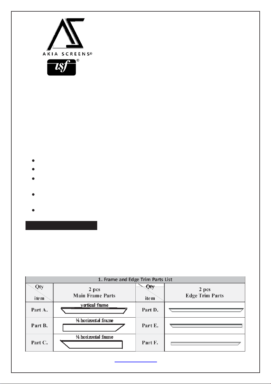
2. Hardware Parts List
a.
b.
c.
d.
e.
f.
g.
h.
i
j.
k.
l.
m.
n.
o.
Rev.101321NAS www.akiascreens.com U-00235 2
Item
Parts List
100"
125"
145"
150"
a.
Frame Center Joints - M5 (bottom position)
4
4
4
4
b.
Frame Elbow Joints M5(bottom position)
8
8
8
8
c.
Edge trim Center Joints M4
2
2
2
2
d.
Edge trim Elbow Joints M4
4
4
4
4
e.
M5x6 Screws
48
48
48
48
f.
Springs
60
75
90
100
g.
Spring Hook
2
2
2
2
h.
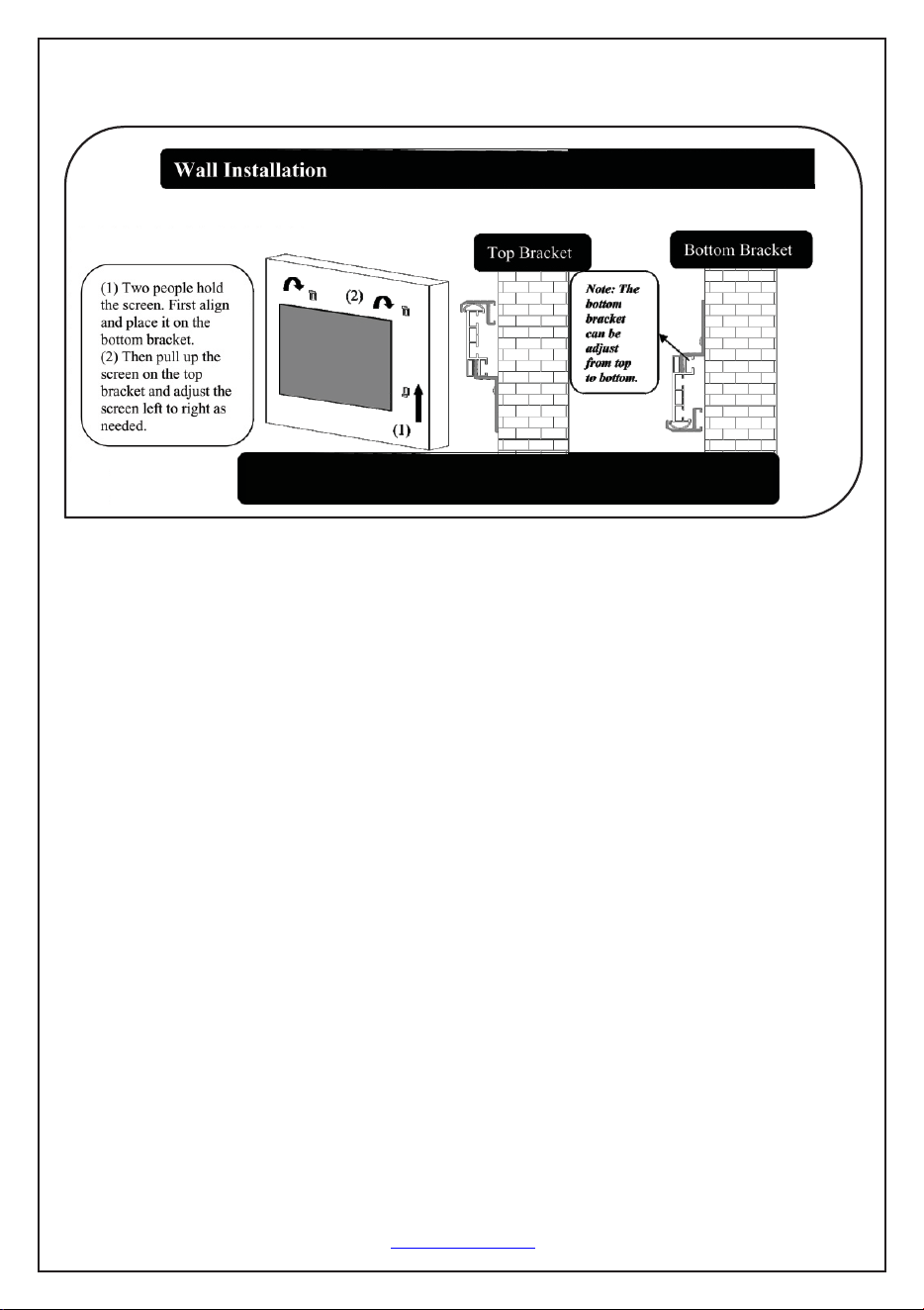
Wall Brackets
4
4
4
4
I
35CSK Wall Screws
8
8
8
8
j.
Hollow Wall anchors
8
8
8
8
k.
M4x4 Screws
24
24
24
24
l.
Center Support Bar
1
1
2
2
m.
White gloves
2
2
2
2
n.
Spring Edge Trim
8
8
8
8
o.
Long rod (sides) / Short rod (top/bottom)
2/4
2/4
2/4
2/4
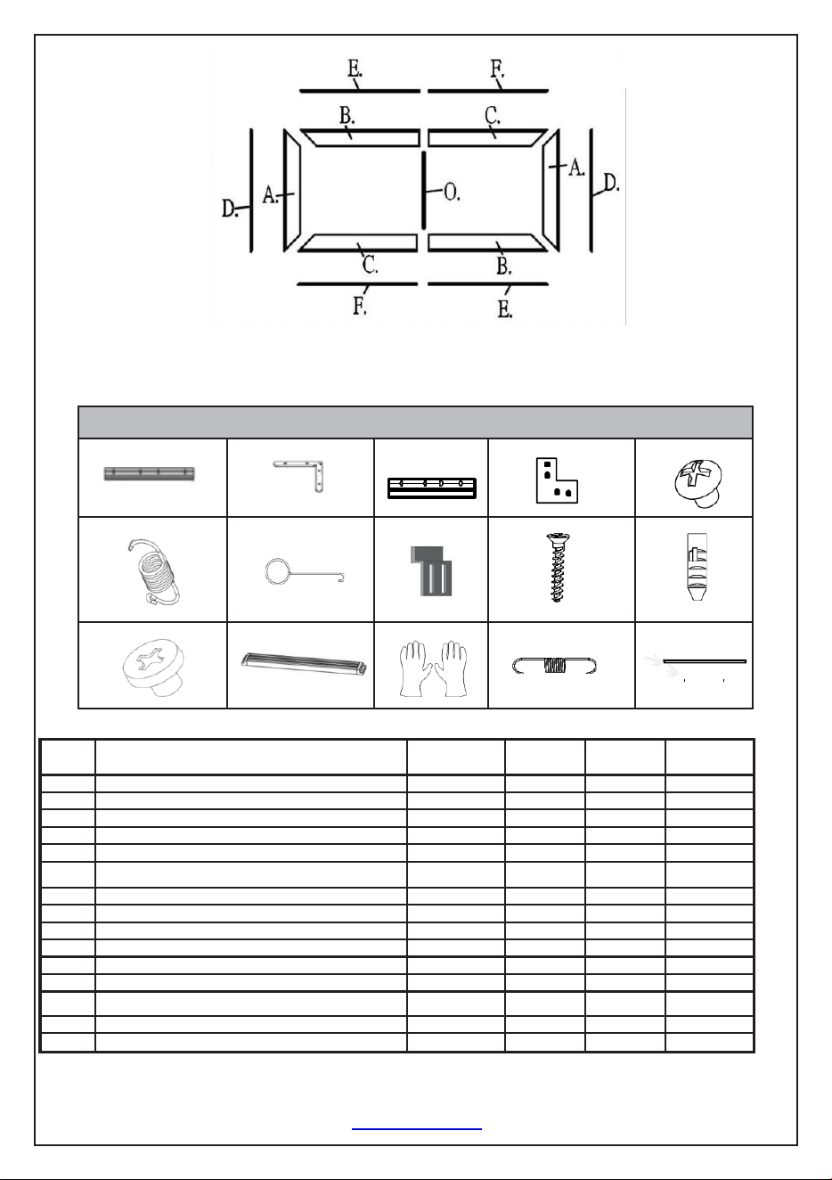
Frame Assembly
Step 1: Position the pieces of the frame in the arrangement shown below.
Corner Connection
Note: Make sure all holes are in alignment and the
frame pieces are flush (no gaps), then fasten the screws.
Corner Connection
Step 2. Place the assembled frame to the side and carefully unroll the screen material
face down on the top of a soft, clean cloth.
Step 3. Insert the four horizontal and two vertical Tension Rods into the corresponding
sides of the screen material, while keeping the material lying flat. Careful not to snag
on the holes at the edge of the material during this process, forcing the rods may
damage the screen material.
Step 4. Connect the elbow joints (b) to the top and bottom sections of the vertical
frame. Once inserted, connect the vertical sections to the horizontal frame sections.
Make sure all holes are in alignment and the frames pieces are flush (no gaps).
They should form perfect right angles.
Rev.101321NAS www.elitescreens.com U-00235 3
To prevent permanent damage to the screen material, be sure your hands are clean for the next step.
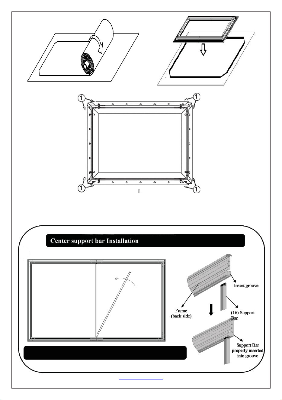
Center Support Bar
Step 5.Secure the elbow joints by fasting them with M5x6 screws (e), 4+4 at each corner.
Rev.101321NAS www.akiascreens.com U-00235 4
See illustration on the right side on how to properly install the Support bar.
Insert the support bar's
tip into the frame's
groove in the middle,
then rotate it and insert
the other end on the
other side of frame.
Step 6: Two people are suggested for this step. Place the center Support Bar into the top
grove on the back of the frame at the approximate center point. Carefully pull the
bottom horizontal frame outward and place the center Support Bar at the approximate
center point of the frame, carefully release the frame once the bar is centered.
(See illustration below)
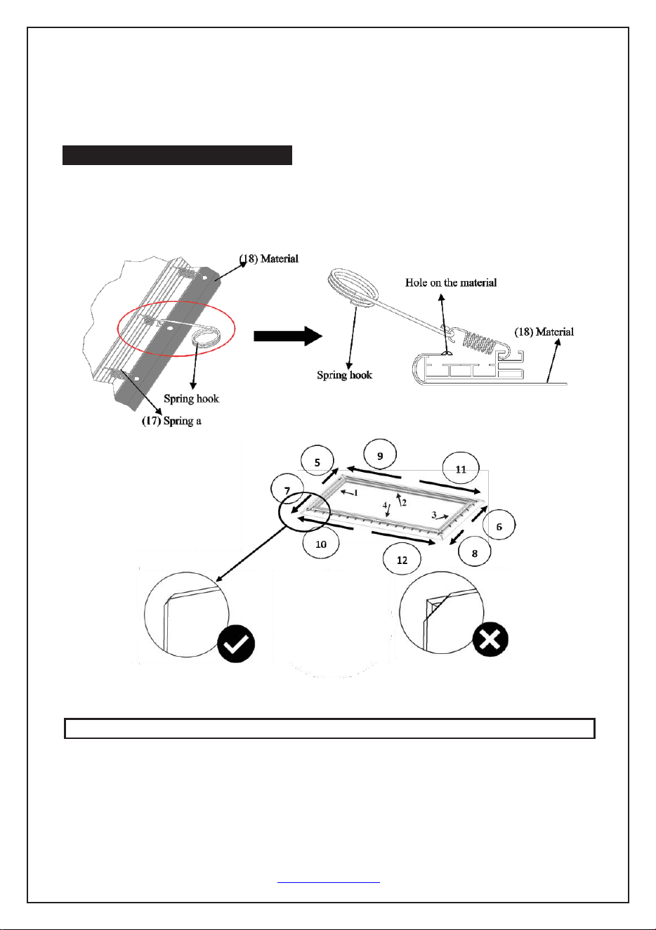
Spring Attachment Method
Step 7. Once the corners and center support bar are secure, continue attaching the
remainder of the springs to the material. Connect the center of the vertical and
horizontal portions of the material, then work your way around the rest of the frame.
Screen Material
Note (after all springs have been attached):
Correct material installation -Corners of the screen material are properly wrapped
around the corner edges of the frame and material is evenly tensioned and flat,
creating a nicely taut surface.
Rev.101321NAS www.akiascreens.com U-00235 5
Attention: Do not proceed with the Edge Trim installation until making sure there are no ripples in the material.
Incorrect material installation -The corners of the screen material are not properly
wrapped along the edge of the frame leaving the material with unbalanced tension and
an uneven finish. To correct, detach springs from material at the corner(s) where
material does not lie flat along the edge of the frame, reposition the material so that it lies
flat and wraps along the edge of the frame, and reattach springs to the material.
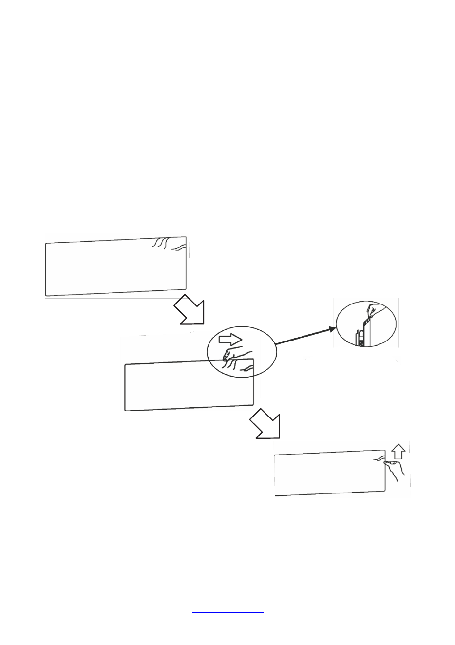
Note: Please make note of the yellow label and spring in the center of the frame. This is
an indicator to start the screen material installation process from the middle area of the
frame.
How to avoid getting ripples on the screen's material surface Solution: Pull and
smooth out the material using your hand from the center to the corners, creating a nicely
taut surface as shown below.
Rev.101321NAS www.akiascreens.com U-00235 6
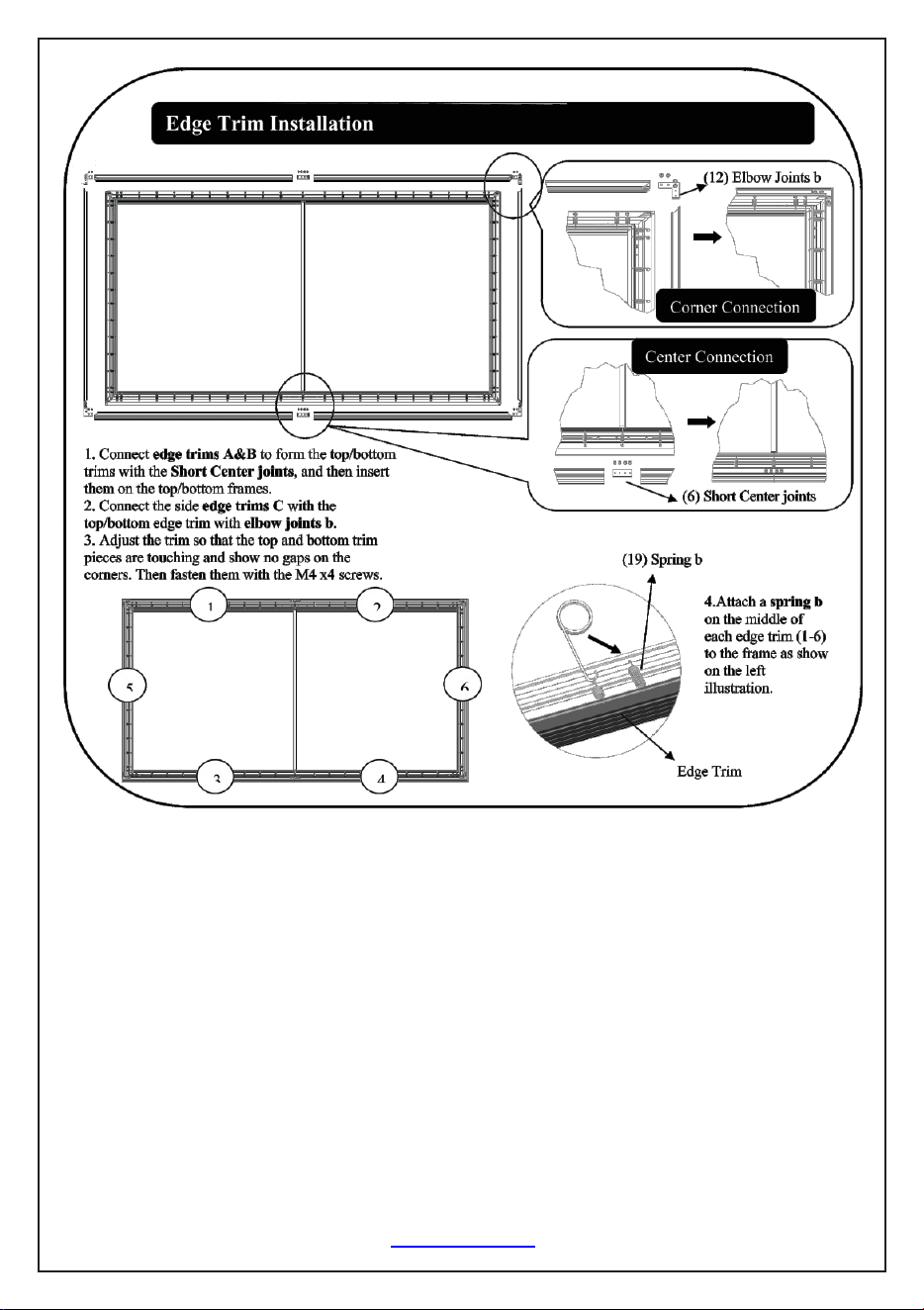
1. Connect edge trims E&F to form the top/ bottom trims with the edge trim center
Joints, and then insert them on the top/bottom frames.
2. Connect the side edge trims C with the top/bottom edge trim with elbow joints D.
3. Adjust the trim so that the top and bottom trim pieces are touching and show no gaps
on the corners. Then fasten them with the M4x4 screws. (k)
4. Attach an edge trim spring (N) on the middle of each edge trim (1-6) to the frame
as show on the left illustration.
Rev.101321NAS www.akiascreens.com U-00235 7