Loading ...
Loading ...
Loading ...
4A. Wiring Instructions (3-Wire Connection)
1. Remove the three (3) loose nutson the terminal block
usinga 3/8" nut driveror socket.
NOTE: Do not loosen the nuts whichsecure the factory
installed range wiring to the terminal block. Electrical
failure or lossof electricalconnectionmay occurifnuts
areloosened.
2. Usingthe nuts removed in step 1, connectthe cable or
copper power supply cord to the three (3) studs on the
terminal block, as local codes require. The neutral (white)
wire or center wire must be connected to the center
terminal.
3. Make sure all nuts are tightened securely.
4. Replace the rear access cover.
GROUNDING INSTRUCTIONS:
A ground link is installed on this range which connects the
center terminal of the terminal block (neutral) to the chassis.
The ground link is not visible in the picture below but is
connected to the range by the center, lowest screw (shown in
picture below). The ground link must not be removed unless
national or local codes do not permit use of ground link.
NOTE: If the ground link is removed for any reason, a
separate ground wire must be connected to the separate
ground screw attached to the range chassis and to an
adequate ground source.
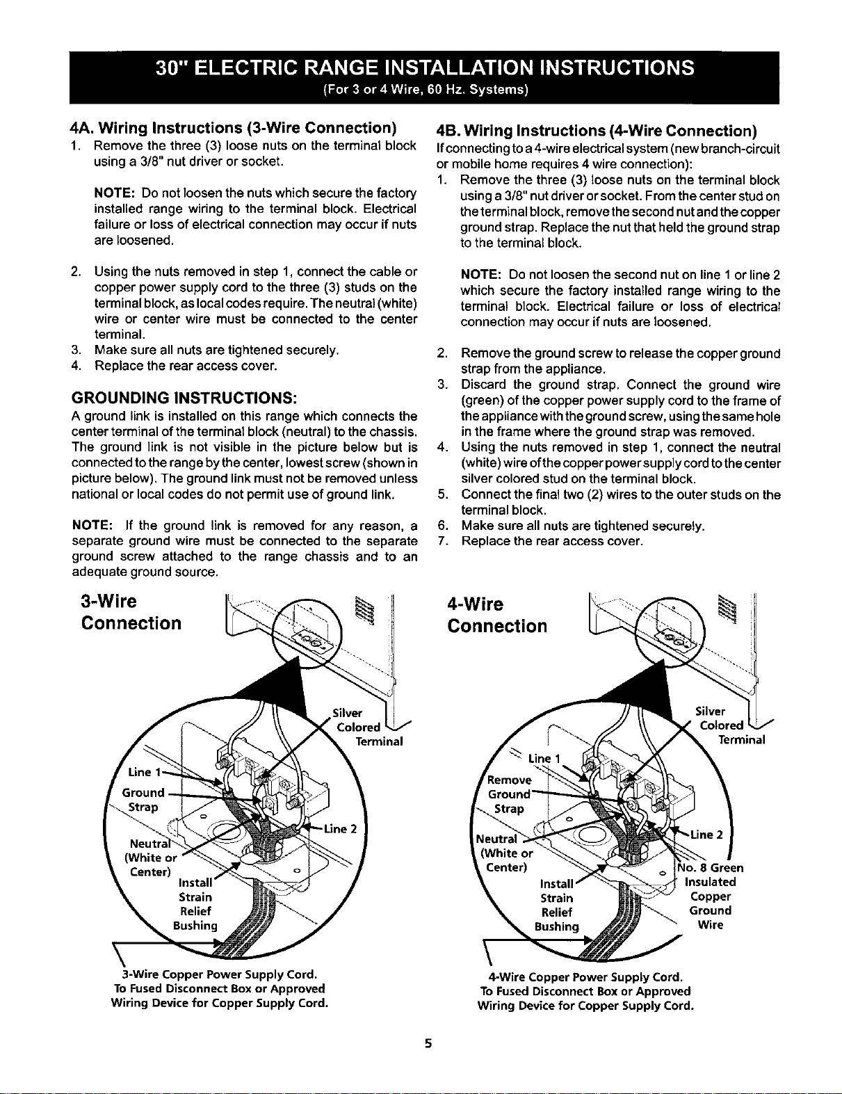
3-Wire
Connection
4B. Wiring Instructions (4-Wire Connection)
Ifconnectingtoa 4-wireelectricalsystem(newbranch-circuit
or mobilehome requires4 wire connection):
1. Remove the three (3) loose nutson the terminal block
usinga 3/8" nutdriverorsocket. Fromthe center studon
theterminalblock, removethesecondnutandthecopper
groundstrap. Replacethenutthatheldthe groundstrap
to the terminal block.
NOTE: Do not loosenthe second nut on line 1 or line 2
which secure the factory installed range wiring to the
terminal block. Electrical failure or loss of electrical
connection may occur if nuts are loosened.
2. Remove the ground screw torelease the copper ground
strapfrom the appliance.
3. Discard the ground strap. Connect the ground wire
(green) of thecopper powersupplycordto theframe of
theappliancewiththegroundscrew,usingthesamehole
in the frame where the groundstrapwas removed.
4. Using the nuts removed in step 1, connectthe neutral
(white)wireofthecopperpowersupplycordtothecenter
silvercoloredstud on theterminal block.
5. Connect the finaltwo(2) wires tothe outerstudson the
terminal block.
6. Make sure all nuts aretightenedsecurely.
7. Replace the rear access cover.
4-Wire
Connection
Terminal
CoJore,
Terminal
\
3-Wire Copper Power Supply Cord.
To Fused Disconnect Box or Approved
Wiring Device for Copper Supply Cord.
4-Wire Copper Power Supply Cord.
To Fused Disconnect Box or Approved
Wiring Device for Copper Supply Cord.
40. 8 Green
Insulated
Copper
Ground
Wire
Loading ...