Whether it’s providing information about specific product
features, taking a tour through your vehicle’s heritage, knowing
what steps to take following an accident or scheduling your
next appointment, we know you’ll find the app an important extension of
your RAM vehicle.
Simply download the app, select your make and model and enjoy the ride.
To get this app, go directly to the App Store or Google Play and enter the
search keyword “ram toolbox” (U.S. residents only).
WWW.RAMTRUCKS.COM/EN/OWNERS (U.S.) provides special offers
tailored to your needs, customized vehicle galleries, personalized service
records and more. To get this information, just create an account and
check back often.
Get warranty and other information online – you can review and print
or download a copy of the Owner’s Manual, Navigation/Uconnect manuals
and the limited warranties provided by FCA US LLC for your vehicle by
visiting WWW.MOPAR.COM (U.S.) or WWW.OWNERS.MOPAR.CA (Canada).
Click on the applicable link in the “Popular Topics” area of the
WWW.MOPAR.COM (U.S.) or WWW.OWNERS.MOPAR.CA (Canada) homepage
and follow the instructions to select the applicable year, make and model
of your vehicle.
DOWNLOAD A FREE
ELECTRONIC COPY OF THE
MOST UP-TO-DATE OWNER’S
MANUAL, MEDIA AND
WARRANTY BOOKLET
BY VISITING:
WWW.MOPAR.COM/EN-US/CARE/
OWNERS MANUAL.HTML
(U.S. RESIDENTS);
WWW.OWNERS.MOPAR.CA
(CANADIAN RESIDENTS).
RAMTRUCKS.COM (U.S.)
RAMTRUCKS.CA (CANADA)
©2018 FCA US LLC. All Rights Reserved.
RAM is a registered trademark of FCA US LLC.
19DT-926-AA
Fourth EDITION
2019 USER GUIDE
RAM 1500
THE ALL-NEW
3405575_19d_RAM_1500_UG_021518.indd 1 2/15/18 2:28 PM

IMPORTANT
Get warranty and other information online – you can review and print or download a copy of the Owner’s Manual, Navigation/
Uconnect manuals and the limited warranties provided by FCA US LLC for your vehicle by visiting www.mopar.com (U.S.) or
www.owners.mopar.ca (Canada). Click on the applicable link in the “Popular Topics” area of the www.mopar.com (U.S.) or
www.owners.mopar.ca (Canada) homepage and follow the instructions to select the applicable year, make and model of your vehicle.
This User Guide is intended to familiarize you with the important features of your vehicle. Your Owner’s Manual, Navigation/Uconnect
manuals and Warranty Booklet can be found by visiting the website on the back cover of your User Guide. We hope you find these
resources useful. U.S. residents can purchase replacement kits by visiting www.techauthority.com and Canadian residents can
purchase replacement kits by calling 1 800 387-1143.
The driver’s primary responsibility is the safe operation of the vehicle. Driving while distracted can result in loss of vehicle control, resulting
in a collision and personal injury. FCA US LLC strongly recommends that the driver use extreme caution when using any device or feature
that may take their attention off the road. Use of any electrical devices, such as cellular telephones, computers, portable radios, vehicle
navigation or other devices, by the driver while the vehicle is moving is dangerous and could lead to a serious collision. Texting while driving
is also dangerous and should never be done while the vehicle is moving. If you find yourself unable to devote your full attention to vehicle
operation, pull off the road to a safe location and stop your vehicle. Some states or provinces prohibit the use of cellular telephones or
texting while driving. It is always the driver’s responsibility to comply with all local laws.
This guide has been prepared to help you get quickly acquainted with your new RAM brand vehicle and to provide a convenient reference
for common questions. However, it is not a substitute for your Owner’s Manual.
For complete operational instructions, maintenance procedures and important safety messages, please consult your Owner’s Manual,
Navigation/Uconnect manuals found on the website on the back cover and other Warning Labels in your vehicle.
Not all features shown in this guide may apply to your vehicle. For additional information on accessories to help personalize your vehicle,
visit www.mopar.com (U.S.), www.mopar.ca (Canada) or your local RAM brand dealer.
DRIVING AND ALCOHOL
Drunken driving is one of the most frequent causes of collisions. Your driving ability can be seriously impaired with blood alcohol
levels far below the legal minimum. If you are drinking, don’t drive. Ride with a designated non-drinking driver, call a cab, a friend
or use public transportation.
WARNING
Driving after drinking can lead to a collision. Your perceptions are less sharp, your reflexes are slower and your judgment is
impaired when you have been drinking. Never drink and then drive.
3405575_19d_RAM_1500_UG_021518.indd 2 2/15/18 2:28 PM

1
WELCOME FROM FCA US LLC
Congratulations on selecting your new FCA
US LLC vehicle. Be assured that it
represents precision workmanship, distinc
-
tive styling, and high quality.
ALWAYS drive safely and pay attention to the
road. ALWA
YS drive safely with your hands
on the steering wheel. You have full respon
-
sibility and assume all risks related to the
use of the
features and applications in this
vehicle. Only use the features and applica
-
tions when it is safe to do so. Failure to do so
may result
in an accident involving serious
injury or death.
This guide illustrates and describes the oper-
ation of features and equipment that are
either sta
ndard or optional on this vehicle.
This guide may also include a description of
features and equipment that are no longer
available or were not ordered on this vehicle.
Please disregard any features and equipment
described in this guide that are not available
on this vehicle. FCA US LLC reserves the
right to make changes in design and specifi
-
cations and/or make additions to or improve-
ments to its products without imposing any
o
bligation
upon itself to install them on prod-
ucts previously manufactured.
This User Guide has been prepared to help
you quickl
y become acquainted with the
important features of your vehicle. It
contains most things you will need to operate
and maintain the vehicle, including emer
-
gency information.
When it comes to service, remember that
y
our autho
rized dealer knows your vehicle
best, has factory-trained technicians and
genuine MOPAR® parts, and cares about
your satisfaction.
HOW TO FIND YOUR
OWNER’S MANUAL ONLINE
This publication has been prepared as a
reference item to help you quickly become
acquainted with the most important features
and processes of your vehicle. It contains
most things you will need to operate and
maintain the vehicle, including emergency
information and procedures.
This User Guide is not a replacement for the full
Owner’s Ma
nual, and does not fully cover every
operation and procedure possible with your
vehicle.
For more detailed descriptions of the topics
discussed
in this User Guide, as well as
information covering features and processes
not covered in this User Guide, the full
vehicle Owner’s Manual can be accessed for
free online in a printer-friendly PDF format.
To get the full Owner’s Manual or applicable
supplement for your vehicle, follow the appro-
priate web address below:
www.mopar.com/en-us/care/
owners-manual.html (U.S. Residents)
www.owners.mopar.ca (Canadian Residents)
FCA US LLC is committed to protecting our
e
nvironmen
t and natural resources. By
converting from paper to electronic delivery
for the majority of the user information for
your vehicle, together we greatly reduce the
demand for tree-based products and lessen
the stress on our environment.

2
INTRODUCTION
HOW TO USE THIS MANUAL
Essential Information
Each time direction instructions (left/right or
forwards/backwards) about the vehicle are
given, these must be intended as regarding
an occupant in the driver's seat. Special
cases not complying with this rule will be
properly specified in the text.
The figures in this User Guide are provided
by way of
example only: this might imply that
some details of the image do not correspond
to the actual arrangement of your vehicle.
In addition, the User Guide has been
conceived
considering vehicles with the
steering wheel on the left side; it is therefore
possible that in vehicles with the steering
wheel on the right side, the position or
construction of some controls is not exactly
mirror-like with respect to the figure.
To identify the chapter with the information
needed you
can consult the index at the end
of this User Guide.
Chapters can be rapidly identified with dedi-
cated graphic tabs, at the side of each odd
page. A fe
w pages further there is a key for
getting to know the chapter order and the
relevant symbols in the tabs. There is always
a textual indication of the current chapter at
the side of each even page.
Symbols
Some vehicle components have colored
labels whose symbols indicate precautions to
be observed when using this component.
Refer to “Warning Lights and Messages” in
“Getting To Know Your Instrument Panel”
for further information on the symbols used
in your vehicle.
WARNINGS AND CAUTIONS
While reading this User Guide you will find a
series of WARNINGS to be followed to
prevent incorrect use of components which
could cause accidents or injuries.
There are also CAUTIONS that must be
followed t
o prevent against procedures that
could result in damage to your vehicle.
VAN CONVERSIONS/
CAMPERS
The New Vehicle Limited Warranty does not
apply to body modifications or special equip-
ment installed by van conversion/camper
m
anufactur
ers/body builders. U.S. residents
refer to the Warranty Information book,
Section 2.1.C. Canadian residents refer to
the “What Is Not Covered” section of the
Warranty Information book. Such equipment
includes video monitors, VCRs, heaters,
stoves, refrigerators, etc. For warranty
coverage and service on these items, contact
the applicable manufacturer.
Operating instructions for the special equip-
ment installed by the conversion/camper
manufactur
er should also be supplied with
your vehicle. If these instructions are
missing, please contact your authorized
dealer for assistance in obtaining replace
-
ment documents from the applicable manu-
facturer.
For information on the Body Builder’s Guide
r
efer to ww
w.rambodybuilder.com. This
website contains dimensional and technical
s
pecificat
ions for your vehicle. It is intended
for Second Stage Manufacturer's technical
support. For service issues, contact your
authorized dealer.


4
WELCOME FROM FCA US LLC
HOW TO FIND YOUR OWNER’S MANUAL
ONLINE ................................................1
INTRODUCTION
HOW TO USE THIS MANUAL ................2
Essential Information ................2
Symbols
.................................. 2
WARNINGS AND CAUTIONS
.................
2
VAN CONVERSIONS/CAMPERS.............
2
GETTING TO KNOW YOUR VEHICLE
KEYS ................................................11
Key Fob................................... 11
IGNITION SWITCH...............................13
K
eyless Pus
h Button Ignition .....13
REMOTE ST
ART — IF EQUIPPED ..........14
How To Use Remote Start .
........ 14
To
Enter Remote Start Mode......15
Gener
al Information ...........
...... 15
VEHICLE SECURITY ALARM .................15
To Arm The System .
..........
....... 15
To Disarm The System ...........
...16
DOORS ..............................................16
Power Side Steps — If
Equipped .
............................... 16
Keyless Ente
r-N-Go — Passive
Entry .
..................................... 16
Child-Protectio
n Door Lock ....... 19
SEATS
...............................................19
Driver Memory Seats — If
Equipped.
................................ 19
Heated Seat
s — If Equipped ..... 22
Ventilate
d Seats — If
Equipped.
................................ 23
HEAD RESTRAINTS .............................23
Fro
nt Head Restraints.
..........
.... 24
Rear Head Restraints...........
..... 24
STEERING WHEEL ..............................25
Tilt/Telescoping Steering
Column .
.................................. 25
Heated Stee
ring Wheel — If
Equipped .
............................... 26
DRIVER ADJUSTABLE PEDALS —
IF
EQUIPPED..........................................26
MIRRORS ..........................................27
Tilt Side Mirrors In Reverse — If
Equipped.
................................ 27
Power Folding O
utside Mirrors For
Standard And Trailer Tow — If
Equipped.
................................ 27
EXTERIOR LIGHTS...............................28
He
adlight Switch.
..........
........... 28
Daytime Running Lights (DRL) — If
Equipped .
............................... 29
Multifunction Leve
r ...........
...... 29
High/Low Beam Switch...........
.. 29
Automatic High Beam Headlamp
Control — If Equipped .
..........
.. 29
Flash-To-Pass ...........
............... 30
Automatic Headlights ...........
.... 30
Parking Lights And Panel
Lights .
.................................... 31
Headlights On W
ith Wipers
(Available With Automatic
Headlights Only) .
..........
........... 31
Headlight Delay ...........
............ 31
Lights-On Reminder ...........
...... 31
Front Fog Lights — If
Equipped .
..........
.................... 31
Turn Signals ...........
................. 31
Cargo Light With Bed Lights — If
Equipped .
............................... 32
Battery Sa
ver ...........
................ 32
WINDSHIELD WIPERS AND WASHERS..33
Windshield Wipers.
..........
......... 33
Rain Sensing Wipers — If
Equipped .
............................... 34

5
CLIMATE CONTROLS ..........................34
Climate Controls With A
Touchscreen Overview.
.........
..... 35
Climate Control Functions .........4
2
Automatic Temperature Control
(ATC) .
.....................................42
Operating Tips
..........
...............43
WINDOWS .........................................44
Power Windo
ws ..........
.............44
Wind Buffeting ..........
..............45
POWER SUNROOF — IF EQUIPPED .......45
Single Pane Power Sunroof — If
Equipped.
................................ 45
Dual Pane Po
wer Sunroof — If
Equipped.
................................ 47
HOOD.................................................50
To Open
The H
ood ..........
......... 50
To Close The Hood..........
..........50
TAILGATE...........................................50
Opening.....
.............................. 50
Closing .....
...............................51
GARAGE DOOR OPENER — IF
EQUIPPED .........................................51
Before You Begin Programming
HomeLink.
............................... 52
Canadian/Gate
Operator
Programming .
.........
................. 53
Using HomeLink ..........
............ 54
Security................................... 54
Troubleshooting
Tips ..........
...... 54
General Information..........
........ 55
INTERNAL EQUIPMENT........................55
Electrical Power Outlets .
.........
.. 55
Power Inverter — If Equipped ... 57
Wireless
Charging Pad — If
Equipped .
............................... 59
PICKUP BOX ......................................59
RAMBOX — IF EQU
IPPED ...................60
RamBox Integrated Box Side Storage
Bins.
....................................... 60
RamBox Sa
fety Warning..........
.. 61
Bed Divider — If Equipped ....... 62
Be
d Rail Tie-Down System ........ 62
SL
IDE-IN CAMPERS ...........................63
Camper Applications.
.........
....... 63
EASY-OFF TAILGATE ..........................63
Disconnecting The Rear Camera And
Remote Keyless Entry.
.........
..... 63
Removing The Tailgate ..........
... 63
Locking Tailgate..........
............. 64
TRI-FOLD TONNEAU COVER — IF
EQUIPPED..........................................64
Tri-Fold Tonneau Cover
Removal.
................................. 64
Tri-Fold Tonneau C
over
Installation .
.........
.................... 65
Tri-Fold Tonneau Cover
Cleaning.
................................. 65
GETTING TO KNOW YOUR
INSTRUMENT PANEL
INSTRUMENT CLUSTER DISPLAY.........66
Instrument Cluster Display
Controls .
................................. 66
Oil Life Rese
t..........
................. 67
Display Menu Items..........
........ 67

6
WARNING LIGHTS AND MESSAGES ......68
Red Warning Lights ..........
........ 68
Yellow Warning Lights..........
..... 71
Yellow Indicator Lights..........
.... 74
Green Indicator Lights..........
..... 76
White Indicator Lights..........
..... 77
Blue Indicator Lights ..........
...... 78
ONBOARD DIAGNOSTIC SYSTEM —
OBD II ...................
............................78
Onboard Diag
nostic System (OBD II)
Cybersecurity .
.........
.................78
SAFETY
AUXILIARY DRIVING SYSTEMS ............80
Blind Spot Monitoring (BSM) — If
Equipped .
...............................80
Forward Collis
ion Warning (FCW)
With Mitigation — If Equipped .
. 82
Tire Pres
sure Monitoring System
(TPMS) .
.................................. 84
OCCUPANT RESTRAINT SYSTE
MS .......89
Occupant Restraint Systems
Features .
................................ 89
Important S
afety Precautions..... 89
Seat
Belt Systems ..........
......... 90
Supplemental Restraint Systems
(SRS).
..................................... 97
Child Restraint
s ..........
........... 110
Transporting Pets ..........
........ 125
SAFETY TIPS ...................................125
Transporting Passengers.
.........
125
Exhaust Gas..........
................. 125
Safety Checks You Should Make
Inside The Vehicle .
.........
....... 126
Periodic Safety Checks You Should
Make Outside The Vehicle .
...... 127
STARTING AND OPERATING
STARTING THE ENGINE ....................128
Normal Starting Using ENGINE
START/STOP Button .
.........
.... 128
ENGINE BLOCK HEATER — IF
EQUIPPED .......................................130
ENGINE BREAK-IN
RECOMMENDATIONS ........................131
PARKING BRAKE...............................131
Electric Park Brake (EPB) .
...... 131
AU
TOMATIC TRANSMISSION ............134
Ignition Park Interlock ..........
.. 135
Brake/Transmission Shift Interlock
System .
................................ 135
Eight-Speed A
utomatic
Transmission .
.........
.............. 135
FOUR-WHEEL DRIVE OPERATION — IF
EQUIPPED .......................................137
Four-Position Electronically Shifted
Transfer Case (Eight Speed
Transmission Only) — If
Equipped .
.........
................... 137
Five-Position Electronically Shifted
Transfer Case (Eight Speed
Transmission Only) — If
Equipped .
.........
................... 139
ACTIVE-LEVEL FOUR CORNER AIR
SUSPENSION SYSTEM — IF
EQUIPPED........................................140
Description.
.........
.................. 140
Air Suspension Modes ..........
.. 142
ACTIVE-LEVEL FOUR CORNER AIR
SUSPENSION SYSTEM (REBEL MODELS
ONLY) — IF EQUIPPED......................143
Description.
.........
.................. 143
Air Suspension Modes ..........
.. 145
AXLE LOCKER SYSTEM — IF
EQUIPPED........................................145

7
LIMITED-SLIP DIFFERENTIAL — IF
EQUIPPED ........................................146
STOP/START SYSTEM —
IF
EQUIPPED ..............
..........................147
Automatic
Mode ..........
...........147
Possible Reasons The Engine Does
Not Autostop.
.........
................147
To Start The Engine While In
Autostop Mode .
.........
.............148
To Manually Turn Off The Stop Start
System .
.................................149
To Manually Turn
On The Stop Start
System .
.................................149
System Ma
lfunction ..........
...... 149
SPEED CONTROL — IF EQUIPPED ......149
To Activate .
.........
.................. 150
To Set A Desired Speed..........
.150
To Resume Speed ..........
........150
To Deactivate ..........
..............150
ADAPTIVE CRUISE CONTROL (ACC)
OPERATION......................................151
Activation .
.........
................... 151
To Set A Desired ACC Speed ... 151
To Vary
The Speed Setting ...... 152
To
Resume ..........
.................. 153
Deactivation ..........
................ 153
Setting The Following Distance In
ACC .
..................................... 153
ACC Operat
ion At Stop..........
.. 154
Changing Modes ..........
.......... 154
General Information..........
...... 155
PARKSENSE FRONT AND REAR PARK
ASSIST............................................156
ParkSense Sensors .
.........
....... 157
ParkSense Warning Display ..... 157
Enabling
And Disabling Front And/Or
Rear ParkSense.
.........
............ 157
ParkSense System Usage
Precautions .
.........
................. 157
PARKSENSE ACTIVE PARK ASSIST
SYSTEM ..........................................159
LANESENSE — IF EQUIPPED ............160
LaneSense Operation.
.........
.... 160
Turning LaneSense On Or Off .. 160
LaneSense
Warning Message... 160
Changing
LaneSense Status .... 161
PARKVIEW REAR BACK U
P CAMERA ..161
SURROUND VIEW CAMERA SYSTEM — IF
EQUIPPED........................................163
REFUELING THE VEHICLE .................165
Materials Added To Fuel .
........ 1
66
TRAILER TOWING .............................167
Trailer Towing Weights (Maximum
Trailer Weight Ratings) .
.........
167
Towing Requirements ..........
.. 167
RECREATIONAL TOWING (BEHIND
MOTORHOME, ETC.) ........................171
Towing This Vehicle Behind Another
Vehicle.
................................. 171
Recreationa
l Towing — Two-Wheel
Drive Models.
.........
................ 171
Recreational Towing — Four-Wheel
Drive Models.
.........
................ 172
IN CASE OF EMERGENCY
HAZARD WARNING FLASHERS ..........175
ASSIST AND SOS SYSTEM — IF
EQUIPPED........................................175
BULB REPLACEMENT ........................179
Replacement Bulbs .
.........
..... 179
FUSES .............................................180
Power Distribution Center .
..... 180
Int
ernal Power Distribution
Center .
................................. 183

8
JACKING AND TIRE CHANGING ..........187
Jack Location..........
...............187
Removal Of Jack And Tools .....188
Rem
oving The Spare Tire ........ 18
9
Preparations For Jacking .........1
90
Jacking Instructions..........
...... 191
To Stow The Flat Or Spare ......194
Re
installing The Jack And
Tools .
....................................195
JUMP STARTING ....
..........................196
Preparatio
ns For Jump Start ....196
Jump S
tarting Procedure......... 1
97
IF YOUR ENGINE OVERHEATS ...........198
MANUAL PARK RELEASE ...................199
FREEING A STUCK VEHICLE ..............199
TOWING A DISABLED VEHICLE ...........200
Two-Wheel Drive Models .
........ 2
01
Four-Wheel Drive Models......... 2
02
Emergency Tow Hooks — If
Equipped.
.............................. 202
ENHANCED ACCIDENT
RESPONSE SYSTEM
(EARS) ..................
..........................203
EVENT DATA RECORDER (
EDR)...........203
SERVICING AND MAINTENANCE
SCHEDULED SERVICING ...................204
Maintenance Plan ..........
........ 205
Heavy Duty Use Of The
Vehicle.
................................. 208
ENGINE COMPARTMEN
T....................209
3.6L Engine With Stop/Start .
.. 209
5.7L E
ngine Without Stop/
Start .
.................................... 210
5.7L Engine W
ith Stop/Start.... 211
Check
ing Oil Level..........
........ 212
HOISTING ........................................212
TIRES ..............................................212
Tire Safety Information .
.........
212
Tires — General Information ... 219
Tire Type
s.............................. 223
Spare Tires
— If Equipped ...... 224
Whe
el And Wheel Trim Care ... 225
DEPARTMEN
T OF TRANSPORTATION
UNIFORM TIRE QUALITY GRADES ......226
Treadwear.
............................. 227
Traction Gra
des..........
............ 227
Temperature Grades ..........
..... 227
TECHNICAL SPECIFICATIONS
WHEEL AND TIRE TORQUE
SPECIFICATIONS ..............................228
Torque Specifications .
.........
... 228
FLUID CAPACITIES ...........................228
FLUIDS AND LUBRICANTS ................229
Engine .
................................. 229
Chassis ...
............................. 231
MOPAR ACCESSORIES .....................232
Authe
ntic Accessories By
Mopar .
.................................. 232
MULTIMEDIA
CYBERSECURITY .............................233
UCONNECT 3 WITH 5–INCH DISPLAY — IF
EQUIPPED........................................234
Uconnect 3 With 5–inch Display At A
Glance .
................................. 234
Clock Sett
ing ..........
.............. 235
Audio Setting..........
............... 235
Radio Operation ..........
.......... 235
USB/Audio Jack (AUX)/Bluetooth
Operation .
............................. 236
Voice Text R
eply (Not Compatible
With iPhone) .
.........
............... 237

9
UCONNECT 4C NAV WITH 12-INCH
DISPLAY ..........................................237
Uconnect 4
C NAV At A
Glance .
.................................237
Drag & Dr
op Menu Bar ..........
.. 239
Radio ...................................240
Android Auto —
If Equipped ...241
Apple Ca
rPlay Integration — If
Equipped .
.............................245
UCONNECT SETTIN
GS ......................248
TIPS CONTROLS AND GENERAL
INFORMATION ........
..........................249
Steering W
heel Audio
Controls.
................................249
Reception Co
nditions..........
.... 249
Care And Maintenance ..........
.. 249
Anti-Theft Protection ..........
.... 250
SIRIUSXM GUARDIAN — IF EQUIPPED ....
250
SiriusXM Guardian — If Equipped
(Available on Uconnect 4C/4C NAV
With 8.4–inch or 12–inch
Display) .
............................... 250
SiriusXM Guardia
n Activation .. 251
Download
The Uconnect App .. 251
Renewing
Subscriptions (Uconnect
4C/4C NAV With 8.4-inch or 12-inch
Display) .
............................... 252
Maintaining Your
SiriusXM Guardian
Account .
............................... 252
Built-In Featur
es ..........
......... 252
SiriusXM Guardian Remote
Features .
.............................. 255
IPOD/USB/MEDIA PLAYER CONTROL...
257
Audio Jack (AUX) .
.........
......... 257
USB Port............................... 257
Bluetooth St
reaming Audio...... 258
NAVIGAT
ION ...................................258
Changing The Navigation Voice
Prompt Volume .
.........
............ 258
Finding Points Of Interest ....... 259
Finding
A Place By Spelling The
Name.
................................... 259
One-Step Voic
e Destination
Entry.
.................................... 259
Setting Your
Home Location.... 259
Home
.................................... 260
Adding A Stop
..........
............. 261
Taking A Detour ..........
........... 261
SiriusXM Traffic Plus (4C NAV With
8.4–inch And 12–inch
Display) .
............................... 261
SiriusXM Trave
l Link (4C NAV With
8.4–inch And 12–inch
Display) .
............................... 261

10
UCONNECT PHONE ..........................262
Uconnect Phone (Bluetooth Hands
Free Calling) .
.........
................262
Pairing (Wirelessly Connecting) Your
Mobile Phone To The Uconnect
System .
................................264
Common Phone
Commands
(Examples) .
.........
.................. 268
Mute (Or Unmute) Microphone
During Call .
.........
.................. 268
Transfer Ongoing Call Between
Handset And Vehicle.
.........
..... 268
Phonebook..........
................... 268
Voice Command Tips ..........
.... 269
Changing The Volume ..........
... 269
Using Do Not Disturb ..........
... 269
Incoming Text Messages ........ 26
9
Helpful Tips And Common Questions
To Improve Bluetooth Performance
With Your Uconnect System .
... 270
VOICE RECOGNIT
ION QUICK TIPS .......271
Introducing Uconnect ..........
... 271
Get Started ..........
.................. 271
Basic Voice Commands..........
. 272
Radio .................................... 273
Media ......
............................. 274
Phone ......
............................. 275
Voice Text R
eply — If
Equipped.
.............................. 276
Climate (4C
/4C NAV) ..........
.... 276
Navigation (4C NAV)..........
..... 277
SiriusXM Guardian (4C/4C NAV) —
If Equipped .
.........
................. 278
Register (4C/4C NAV) ..........
... 279
Mobile App (4C/4C NAV)......... 2
79
SiriusXM Travel Link (4C
NAV) .
.................................... 279
Siri Eyes Fr
ee — If Equipped .. 280
Using Do
Not Disturb ..........
... 281
Android Auto — If Equipped ... 281
Apple Ca
rPlay — If Equipped .. 282
General
Information..........
...... 283
Additional Information ..........
.. 284
CUSTOMER ASSISTANCE
IF YOU NEED ASSISTANCE ...............285
FCA US LLC Customer Center285
FCA Canada Inc. Customer
Center.
.................................. 285
In Mexico C
ontact ..........
........ 285
Puerto Rico And U.S. Virgin
Islands.
................................. 285
Customer A
ssistance For The
Hearing Or Speech Impaired (TDD/
TTY) .
.................................... 285
Service Co
ntract ..........
.......... 286
REPORTING SAFETY DEFECTS ...........286
In The 50 United States And
Washington, D.C. .
.........
......... 286
In Canada.............................. 287
PUBLICATION ORDER FORMS
............287
11
KEYS
Key Fob
Your vehicle uses a keyless ignition system.
The ignition system consists of a key fob with
Remote Keyless Entry (RKE) and a START/
STOP push button ignition system. The
Remote Keyless Entry system consists of a
key fob and Keyless Enter-N-Go feature.
NOTE:
The key fob may not be found if it is located
next to a m
obile phone, laptop or other elec-
tronic device; these devices may block the
k
ey fob’s w
ireless signal.
The key fob allows you to lock or unlock all
doors, tail
gate, and the RamBox (if
equipped) as well as activate the Panic
Alarm from distances up to approximately
66
ft (20 m) using a handheld key fob. The
key fob doe
s not need to be pointed at the
vehicle to activate the system.
NOTE:
In the ON/RUN position, all key fob
buttons will work until the vehicle reaches
3
mph (5 km/h).
The key fob should not be placed next to
the wireless charging pad (if equipped).
Key Fob
In case the ignition switch does not change
with the pu
sh of a button, the key fob may
have a low or fully depleted battery. A low key
fob battery can be verified by referring to the
instrument cluster, which will display direc
-
tions to follow.
NOTE:
A low key fob battery condition may be indi-
cated by a message in the instrument cluster
d
isplay, or
by the LED light on the key fob. If
the LED key fob light no longer illuminates
from key fob button pushes, then the key fob
battery requires replacement.
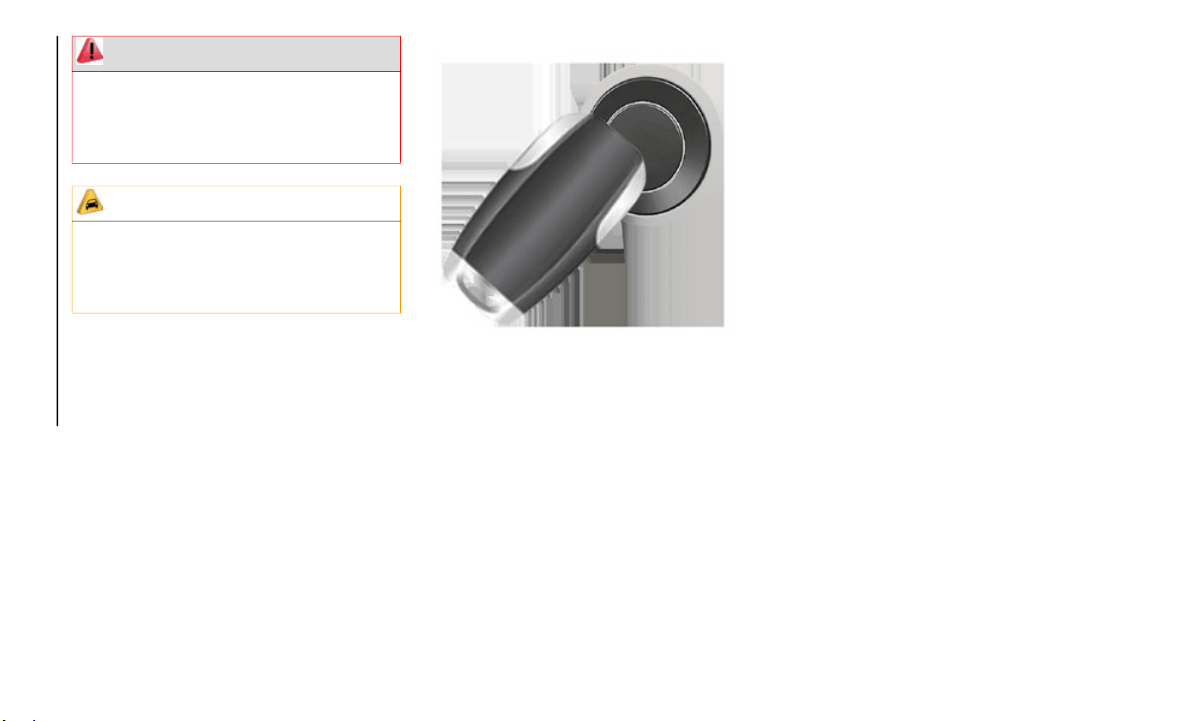
In a situation where the battery is low or fully
depleted, a
back up method can be used to
operate the ignition switch. Put the nose side
of the key fob (side opposite of the Emer
-
gency Key) against the ENGINE START/
STOP button
and push to operate the igni-
tion switch.
To Unlock The Doors And Tailgate
Push and release the unlock button on the
key fob once to unlock the driver’s door.
Push the unlock button twice within five
seconds to unlock all doors, the tailgate and
the RamBox (if equipped). The turn signal
lights will flash to acknowledge the unlock
signal. The illuminated entry system will also
turn on.
NOTE:
The instrument cluster display or Uconnect
Settings ar
e setup for driver door first, other-
wise this will unlock all doors.
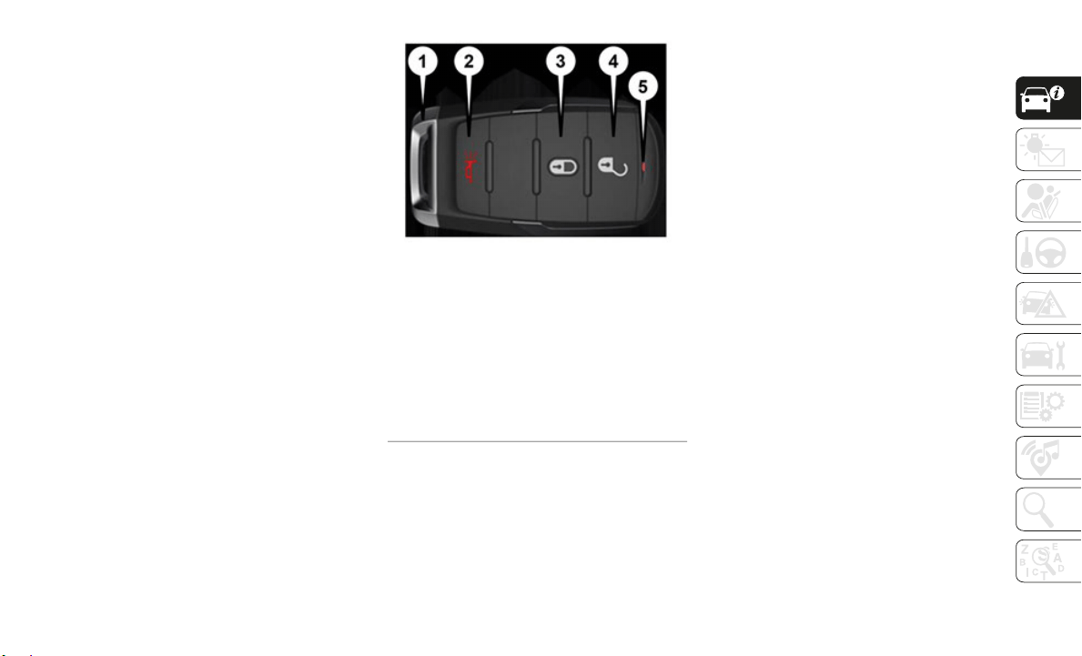
1 — Emergency Key
2 — PANIC
3 — Lock
4 — Unlock
5 — LED Light

GETTING TO KNOW YOUR VEHICLE
12
To Lock The Doors And Tailgate
Push and release the lock button on the key
fob to lock all doors, the tailgate, and the
RamBox (if equipped). The turn signal lights
will flash and the horn will chirp to acknowl
-
edge the signal.
Using The Panic Alarm
To turn the Panic Alarm feature on or off,
push the Panic button on the key fob. When
the Panic Alarm is activated, the turn signals
will flash, the horn will pulse on and off, and
the interior lights will turn on.
The Panic Alarm will stay on for three
minutes un
less you turn it off by either
pushing the Panic button a second time or
drive the vehicle at a speed of 15
mph
(24 km/h) o
r greater.
NOTE:
The interior lights will turn off if you place
the ignition in the ACC or ON/RUN posi-
tion while the Panic Alarm is activated.
H
owever, t
he exterior lights and horn will
remain on.
You may need to be less than 35 ft (11 m)
from the vehicle when using the key fob to
turn off the Panic Alarm due to the radio
frequency noises emitted by the system.
Air Suspension (Remote Lowering Of The
Vehicle) — If Equipped
For easy entry and loading, your
vehicle can be lowered by pushing
the key fo
b air suspension lowering
button two times. When key fob
lowering is requested, the vehicle will send a
series of chirps and flashes to alert the
customer that the operation has begun and
will continue these alerts until it successfully
lowers.
The following conditions must be met for the
vehicle to
lower remotely:
The vehicle must not already be in Entry/
Exit (Park) ride height.
The vehicle battery must be fully charged.
All doors must be closed.
The key fob must be out of the vehicle.
Canceling Remote Lowering
Vehicle lowering can be cancelled at
anytime. W
hen vehicle lowering is cancelled,
the vehicle will raise up to the next defined
level and lock out the remote lowering
feature until the ignition has been cycled
ON/OFF.
To cancel vehicle lowering, push the key fob
air suspen
sion lowering button one time
during the lowering process. When vehicle
lowering is cancelled, the horn will chirp two
times and the turn signal lamps will flash
four times. Once raising is completed, the
horn will chirp one time.
NOTE:
Refer to “Active-Level Four Corner Air
Suspension
System” in “Starting And Oper-
ating” in the Owner’s Manual for further
i
nformatio
n.
General Information
The following regulatory statement applies to
all radio frequency (RF) devices equipped in
this vehicle:
This device complies with Part 15 of the FCC
Rules and
with Industry Canada
license-exempt RSS standard(s). Operation
is subject to the following two conditions:
1. This device may not cause harmful inter-
ference,
and
2. This device must accept any interference
received,
including interference that may
cause undesired operation.
13
(Continued)
NOTE:
Changes or modifications not expressly
approved
by the party responsible for compli-
ance could void the user’s authority to
o
perate t
he equipment.
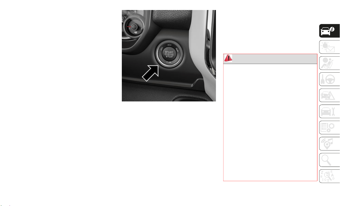
IGNITION SWITCH
Keyless Push Button Ignition
This feature allows the driver to operate the
ignition switch with the push of a button as
long as the Remote Keyless Entry key fob is
in the passenger compartment.
The Keyless Push Button Ignition has four
operating
positions; three of which are
labeled and will illuminate when in position.
The three positions are OFF, ACC, and ON/
RUN. The fourth position is START, during
start RUN will illuminate.
NOTE:
In case the ignition switch does not change
with the
push of a button, the key fob may
have a low or dead battery. In this situation,
a back up method can be used to operate the
ignition switch. Put the nose side (side oppo
-
site of the emergency key) of the key fob
against t
he ENGINE START/STOP button,
with your foot applied on the brake pedal,
and push to operate the ignition switch.
Keyless Push Button Ignition
The push button ignition can be placed in
t
he follo
wing modes:
OFF
The engine is stopped.
Some electrical devices (e.g. Central
locking, alarm, etc.) are still available.
ACC
Engine is not started.
Some electrical devices are available.
RUN
Driving position.
All the electrical devices are available.
START
The engine will start.
WARNING!
When exiting the vehicle, always remove
the key fob from the vehicle and lock
your vehicle.
Never leave children alone in a vehicle,
or with access to an unlocked vehicle.
Allowing children to be in a vehicle unat-
tended is dangerous for a number of
reasons.
A child or others could be seri-
ously or fatally injured. Children should
b
e warned
not to touch the parking
brake, brake pedal or the gear selector.
Do not leave the key fob in or near the
vehicle, or in a location accessible to
children, and do not leave the ignition of
a vehicle equipped with Keyless
Enter-N-Go in the ON/RUN mode. A
child could operate power windows,
other controls, or move the vehicle.
GETTING TO KNOW YOUR VEHICLE
14
The engine only runs in the ON/RUN ignition
position or from a remote start request.
In case the ignition switch does not change
with the
push of a button, the key fob may
have a low or dead battery. In this situation,
a back up method can be used to operate the
ignition switch. Put the nose side (side oppo
-
site of the emergency key) of the key fob
against t
he ENGINE START/STOP button
and push to operate the ignition switch.
Back Up Starting Method
NOTE:
The key fob may not be able to be detected
b
y the ve
hicle keyless-go system if it is
located next to a mobile phone, laptop or
other electronic device; these devices may
block the key fob’s wireless signal and
prevent the keyless-go system from starting
the vehicle.
NOTE:
Refer to "Starting The Engine," in "Starting
And Opera
ting" in the Owner’s Manual for
further information.
REMOTE START — IF
EQUIPPED
How To Use Remote Start
All of the following conditions must be met
before the engine will remote start:
Gear selector in PARK
Doors closed
Hood closed
HAZARD switch off
BRAKE switch inactive (brake pedal not
pushed)
Battery at an acceptable charge level
PANIC button not pushed
Fuel meets minimum requirement
System not disabled from previous remote
start event
Vehicle security alarm not active
Do not leave children or animals inside
parked vehicles in hot weather. Interior
heat build-up may cause serious injury or
death.
CAUTION!
An unlocked vehicle is an invitation for
thieves. Always remove key fob from the
vehicle and lock all doors when leaving the
vehicle unattended.
WARNING! (Continued)

15
To Enter Remote Start Mode
Push and release the Remote Start button
on the key fob twice within five seconds. The
parking li
ghts will flash, vehicle doors will
lock, and the horn will chirp twice (if
programmed). Once the vehicle has started,
the engine will run for 15
minutes.
NOTE:
If your power door locks were unlocked,
Remote Start will automatically lock the
doors.
If an engine fault is present or fuel level is
low, the vehicle will start and then shut
down in 10 seconds.
The park lamps will turn on and remain on
during Remote Start mode.
For security, power window and power
sunroof operation (if equipped) are
disabled when the vehicle is in the
Remote Start mode.
The engine can be started two consecutive
times (two 15-minute cycles) with the key
fob. However, the ignition must be placed
in the ON/RUN position before you can
repeat the start sequence for a third cycle.
General Information
The following regulatory statement applies to
all radio frequency (RF) devices equipped in
this vehicle:
This device complies with Part 15 of the FCC
Rules and
with Industry Canada
license-exempt RSS standard(s). Operation
is subject to the following two conditions:
1. This device may not cause harmful inter-
ference,
and
2. This device must accept any interference
received,
including interference that may
cause undesired operation.
NOTE:
Changes or modifications not expressly
approved b
y the party responsible for compli-
ance could void the user’s authority to
o
perate th
e equipment.
VEHICLE SECURITY ALARM
The vehicle security alarm monitors the
vehicle doors, tailgate, and ignition for unau-
thorized operation. When the vehicle security
a
larm is a
ctivated, interior switches for door
locks are disabled. The system will turn the
horn off after 29 seconds, 5 seconds
between cycles, up to 8 cycles if the trigger
remains active and then the vehicle security
alarm will rearm itself.
To Arm The System
Follow these steps to arm the vehicle secu-
rity alarm:
1. Remove the key from the ignition system
(refer to
"Starting The Engine" in
"Starting And Operating" for further infor
-
mation).
Make sure the vehicle ignition system is
"OFF."
WARNING!
Do not start or run an engine in a closed
garage or confined area. Exhaust gas
contains Carbon Monoxide (CO) which is
odorless and colorless. Carbon Monoxide
is poisonous and can cause serious
injury or death when inhaled.
Keep key fobs away from children. Oper-
ation of the Remote Start System,
windows, d
oor locks or other controls
could cause serious injury or death.

GETTING TO KNOW YOUR VEHICLE
16
2. Perform one of the following methods to
lock the vehicle:
Push lock button on the interior power
door lock switch with the driver and/or
passenger door open.
Push the lock button on the exterior
Passive Entry Door Handle with a valid
key fob available in the same exterior
zone (refer to "Keyless Enter- N-Go —
Passive Entry" in "Getting To Know Your
Vehicle" for further information).
Push the lock button on the key fob.
3. If any doors are open, close them.
The vehi
cle security alarm will set when you
use the p
ower door locks, or use the key fob
to lock the doors. After all the doors are
locked and closed, the vehicle security light,
in the instrument panel cluster, will flash
rapidly for about 16 seconds to indicate that
the alarm is being set. After the alarm is set,
the vehicle security light will flash at a slower
rate to indicate that the system is armed.
To Disarm The System
The vehicle security alarm can be disarmed
using any of the following methods:
1. Push the unlock button on the key fob.
2. Grasp
the Passive Entry Unlock Door
Handle w
ith a valid key fob within 5 ft
(1.5 m) o
f the passive entry door handle. If
equipped,
refer to "Keyless Enter-N-Go —
Passive Entry" in "Getting To Know Your
Vehicle" for further information.
3. Place the ignition out of the “OFF” posi-
tion.
The
vehicle security alarm is designed to
protect y
our vehicle. However, you can create
conditions where the system will give you a
false alarm. If one of the previously
described arming sequences has occurred,
the vehicle security alarm will arm regardless
of whether you are in the vehicle or not. If
you remain in the vehicle and open a door,
the alarm will sound. If this occurs, disarm
the vehicle security alarm.
If the vehicle security alarm is armed and the
battery b
ecomes disconnected, the vehicle
security alarm will remain armed when the
battery is reconnected; the exterior lights will
flash, and the horn will sound. If this occurs,
disarm the vehicle security alarm.
DOORS
Power Side Steps — If Equipped
The Power Side Steps will extend a step for
easier entry and exit of the vehicle.
When configured for “Auto” mode, the Power
Side Step
s will deploy when either the
driver’s or passenger’s side door is opened,
or when the deploy setting is activated
through the touchscreen. When configured
for “Store” mode, the steps will stay in their
position but can also be deployed manually
through the radio.
If the vehicle speed exceeds 5 mph (8 km/h),
or if the
retract setting is selected in the touch-
screen, the steps will retract.
Refer to “Uconnect Settings” in “Multi-
media” in the Owner’s Manual for additional
i
nformati
on.
Keyless Enter-N-Go — Passive Entry
The Passive Entry system is an enhancement
to the vehicle’s Remote Keyless Entry system
and a feature of Keyless Enter-N-Go. This
feature allows you to lock and unlock the
vehicle’s door(s) without having to push the
key fob lock or unlock buttons.
17
NOTE:
Refer to “Uconnect Settings” in “Multi-
media” in the Owner’s Manual for further
informati
on.
If wearing gloves on your hands, or if it has
been raining/snowing on the Passive Entry
door handle, the unlock sensitivity can be
affected, resulting in a slower response
time.
If the vehicle is unlocked by Passive Entry
and no door is opened within 60 seconds,
the vehicle will re-lock and if equipped
will arm the security alarm.
The vehicles security alarm can be armed/
disarmed by pushing the passive entry key
fob lock/unlock buttons (if equipped).
The key fob may not be able to be detected
by the vehicle passive entry system if it is
located next to a mobile phone, laptop or
other electronic device; these devices may
block the key fob's wireless signal and
prevent the passive entry handle from
locking/unlocking the vehicle.
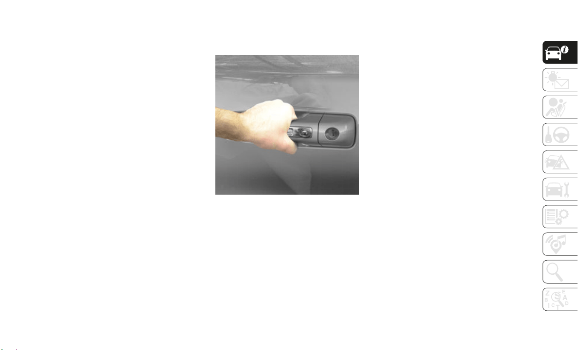
To Unlock From The Driver's Side:
With a valid Passive Entry key fob within 5 ft
(1.5 m) of
the driver door handle, grab the
front dri
ver door handle to unlock the driver's
door automatically. The interior door panel
lock knob will raise when the door is
unlocked.
Grab The Door Handle To Unlock
NOTE:
If “Unlock All Doors 1st Press” is
programme
d, all doors will unlock when you
grab hold of the front driver’s door handle. To
select between “Unlock Driver Door 1st
Press” and “Unlock All Doors 1st Press,”
refer to “Uconnect Settings” in “Multi
-
media” in the Owner’s Manual for further
i
nformati
on.
To Unlock From The Passenger Side:
With a valid Passive Entry key fob within 5 ft
(1.5 m) of
the passenger door handle, grab
the front
passenger door handle to unlock all
doors automatically. The interior door panel
lock knob will raise when the door is
unlocked.
NOTE:
All doors will unlock when the front
p
assenger
door handle is grabbed regardless
of the driver’s door unlock preference setting
(“Unlock Driver Door 1st Press” or “Unlock
All Doors 1st Press”).
Preventing Inadvertent Locking Of Passive
Entry Key
Fob In Vehicle:
To minimize the possibility of unintentionally
locking a
Passive Entry key fob inside your
vehicle, the Passive Entry system is
equipped with an automatic door unlock
feature which will function if the ignition
switch is in the OFF position.
If one of the vehicle doors is open and the
door pane
l switch is used to lock the vehicle,
once all open doors have been closed the
vehicle checks the inside and outside of the
vehicle for any valid Passive Entry key fobs.
If one of the vehicle's Passive Entry key fobs
is detected inside the vehicle, and no other
GETTING TO KNOW YOUR VEHICLE
18
valid Passive Entry key fobs are detected
outside the vehicle, the Passive Entry
System automatically unlocks all vehicle
doors and chirps the horn three times (on the
third attempt ALL doors will lock and the
Passive Entry key fob can be locked in the
vehicle).
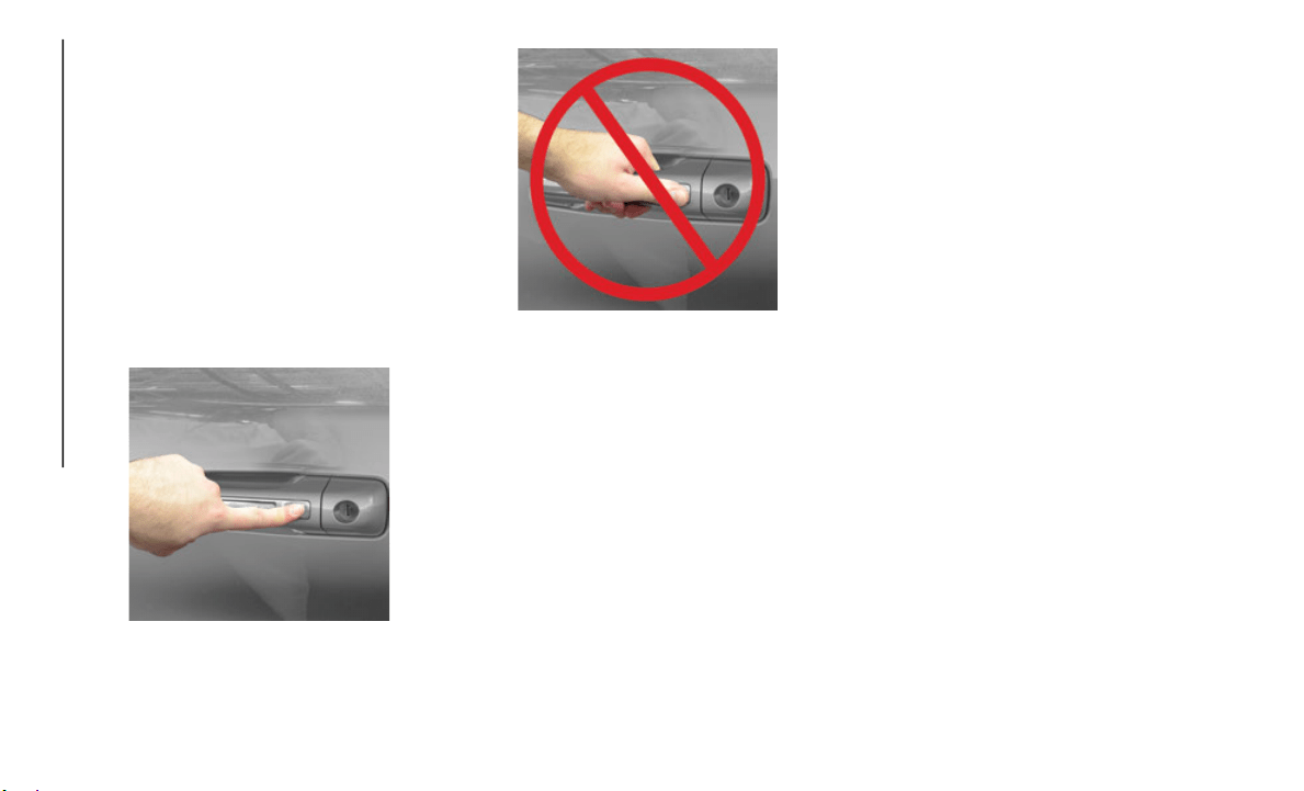
To Lock The Vehicle’s Doors:
With one of the vehicle’s Passive Entry key
fobs with
in 5 ft (1.5 m) of the driver or
passenger
front door handles, push the door
handle lock button to lock all doors.
Push The Door Handle Button To Lock
Do NOT grab the door handle when pushing
t
he door
handle lock button. This could
unlock the door(s).
Do NOT Grab The Door Handle When Locking
NOTE:
After pushing the door handle lock button,
you must wait two seconds before you can
lock or unlock the doors, using either Passive
Entry door handle. This is done to allow you
to check if the vehicle is locked by pulling
the door handle, without the vehicle reacting
and unlocking.
The Passive Entry system depends on a key
fob that is not fully discharged of its coin
battery capacity.
The LED light on the key fob will not blink if
the key fob battery is low or fully depleted,
but a low key fob battery condition will still
support the Passive Entry system function
-
ality. When the key fob battery is low, the
instrumen
t cluster will display a message
indicating that the key fob battery is low.
Refer to “Keys” in “Getting To Know Your
Vehicle” in the Owner’s Manual for further
information.
The vehicle doors can also be locked by using
the key f
ob lock button or the lock button
located on the vehicle’s interior door panel.
General Information
The following regulatory statement applies to
all radio frequency (RF) devices equipped in
this vehicle:
This device complies with Part 15 of the FCC
Rules and
with Industry Canada
license-exempt RSS standard(s). Operation
is subject to the following two conditions:
1. This device may not cause harmful inter-
ference,
and
2. This device must accept any interference
received
, including interference that may
cause undesired operation.
NOTE:
Changes or modifications not expressly
approved
by the party responsible for compli-
ance could void the user’s authority to
o
perate t
he equipment.
19
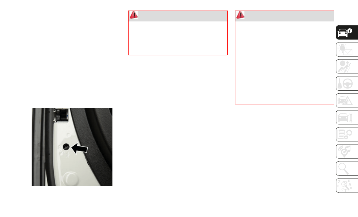
Child-Protection Door Lock
To provide a safer environment for children
riding in the rear seat, the rear doors (if
equipped) of your vehicle have the
Child-Protection Door Lock system.
To use the system, open each rear door, use
a flat bla
de screwdriver (or emergency key)
and rotate the dial to engage and disengage
the Child-Protection locks. When the system
on a door is engaged, that door can only be
opened by using the outside door handle
even if the inside door lock is in the unlocked
position.
Child Lock Control
NOTE:
After setting the Child-Protection Door
Lock system, always test the door from the
inside to make certain it is in the desired
position.
For emergency exit with the system
engaged, move the door lock switch to the
unlock position, roll down the window, and
open the door with the outside door
handle.
SEATS
Seats are a part of the Occupant Restraint
System of the vehicle.
Driver Memory Seats — If Equipped
This feature allows the driver to store up to
two different memory profiles for easy recall
through memory buttons. Each memory
profile contains desired position settings for
the driver’s seat, side mirrors, adjustable
pedals (if equipped), and a set of desired
radio station presets. Your remote keyless
entry key fob can also be programmed to
recall the same positions when the unlock
button is pushed.
WARNING!
Avoid trapping anyone in the vehicle in a
collision. Remember that the sliding doors
cannot be opened from the inside door
handle when the Child Protection Door
Locks are engaged.
WARNING!
It is dangerous to ride in a cargo area,
inside or outside of a vehicle. In a colli-
sion, people riding in these areas are
m
ore likel
y to be seriously injured or
killed.
Do not allow people to ride in any area of
your vehicle that is not equipped with
seats and seat belts. In a collision,
people riding in these areas are more
likely to be seriously injured or killed.
Be sure everyone in your vehicle is in a
seat and using a seat belt properly.

GETTING TO KNOW YOUR VEHICLE
20
NOTE:
Your vehicle is equipped with two key fobs,
one key f
ob can be linked to memory position
1 and the other key fob can be linked to
memory position 2.
The driver memory seat buttons are located
on the dr
iver door, next to the door handle.
Driver Memory Seat Buttons
Programming The Memory Feature
To create a new memory profile, perform the
following:
1. Cycle the vehicle’s ignition to the ON/
RUN posi
tion (do not start the engine).
2. Adjust all memory profile settings to
desired
preferences (i.e., driver’s seat,
outside mirrors, adjustable pedals (if
equipped), and radio station presets).
3. Push and release the set (S) button on
the memo
ry switch.
4. Within five seconds, push and release
either o
f the memory buttons (1) or (2).
The instrument cluster display will show
which memory position has been set.
NOTE:
Memory profiles can be set without the
vehicle in PARK, but the vehicle must be
in PARK to recall a memory profile.
To set a memory profile to your key fob,
refer to “Linking And Unlinking The
Remote Keyless Entry Key Fob To
Memory” in this section.
Linking And Unlinking The Remote Keyless
Entry Key Fob To Memory
Your key fob can be programmed to recall
one of two pre-programmed memory profiles
by pushing the unlock button on the key fob.
NOTE:
Before programming your key fob you must
select th
e “Personal Settings Linked to Key
Fob” feature through the Uconnect Settings.
Refer to “Uconnect Settings” in “Multi
-
media” in your Owner’s Manual for further
informati
on.
To program your key fob, perform the
following
:
1. Cycle the vehicle’s ignition to the OFF
position
.
2. Select a desired memory profile 1 or 2.
NOTE:
If a
memory profile has not already been set,
r
efer to
"Programming The Memory Feature"
in this section for instructions on how to set
a memory profile.
3. Once the profile has been recalled, push
and rele
ase the set (S) button on the
memory switch.

21
4. Push and release button (1) or (2)
accordingly. “Memory Profile Set” (1 or
2) will display in the instrument cluster.
5. Push and release the lock button on the
key fob w
ithin 10 seconds.
NOTE:
Your key fob can be unlinked to your memory
settings b
y pushing the set (S) button, and
within 10 seconds, followed by pushing the
unlock button on the key fob.
Memory Position Recall
NOTE:
The vehicle speed must be lower than 5 mph
(8 km/h) to
recall memory positions. If a
recall is
attempted when the vehicle speed is
greater than 5
mph (8 km/h), a message will
be display
ed in the instrument cluster
display.
Driver One Memory Position Recall
To recall the memory settings for driver
one using the memory buttons on the door
panel, push memory button (1).
To recall the memory settings for driver
one using the key fob, push the unlock
button on the key fob linked to memory
position 1.
Driver Two Memory Position Recall
To recall the memory setting for driver two
using the memory buttons on the door
panel, push memory button (2).
To recall the memory settings for driver
two using the key fob, push the unlock
button on the key fob linked to memory
position 2.
A recall can be cancelled by pushing any of
the memory
buttons during a recall (S, 1, or
2). When a recall is canceled, the driver's
seat and the power pedals (if equipped) stop
moving. A delay of one second will occur
before another recall can be selected.
Easy Entry/Exit Seat
This feature provides automatic driver’s seat
positioning to enhance driver mobility when
entering and exiting the vehicle.
The distance the driver’s seat moves depends
on where y
ou have the driver’s seat positioned
when you remove the key fob from the ignition.
When you remove the key fob from the igni-
tion, the driver’s seat will move about
2.4 inches
(60 mm) rearward if the driver’s
seat posit
ion is greater than or equal to
2.7
inches (67.7 mm) forward of the rear
stop. The
seat will return to its previously set
position when you place the ignition into the
ACC or RUN position.
When you remove the key fob from the igni-
tion, the driver’s seat will move to a position
0.3 inches
(7.7 mm) forward of the rear stop
if the dri
ver’s seat position is between
0.9
inches and 2.7 inches (22.7 mm and
67.7 mm) fo
rward of the rear stop. The seat
will retur
n to its previously set position when
you place the ignition to the ACC or RUN
position.
The Easy Entry/Easy Exit feature is disabled
when the driver’s seat position is less than
0.9
inches (22.7 mm) forward of the rear
stop. At t
his position, there is no benefit to
the driver by moving the seat for Easy Exit or
Easy Entry.
Each stored memory setting will have an asso-
ciated Easy Entry and Easy Exit position.
NOTE:
The Easy Entry/Exit feature is not enabled when
t
he vehicl
e is delivered from the factory. The
Easy Entry/Exit feature is enabled (or later
disabled) through the programmable features
in the Uconnect system.
Refer to “Uconnect Settings” in “Multimedia”
in the Owner’s Manual for further information.

GETTING TO KNOW YOUR VEHICLE
22
Heated Seats — If Equipped
On some models, the front and rear seats
may be equipped with heaters located in the
seat cushions and seat backs.
Front Heated Seats
The heated seats control buttons are located
on the center instrument panel below the
touchscreen, and are also located within the
climate or controls screen of the touch
-
screen.
Push the heated seat button once to
turn the HI setting on.
Push the heated seat button a second
time to turn the MED setting on.
Push the heated seat button a third
time to turn the LO setting on.
Push the heated seat button a fourth
time to turn the heating elements off.
NOTE:
The engine must be running for the heated
seats to operate.
The level of heat selected will stay on until
the operator changes it.
Vehicles Equipped With Remote Start
On models that are equipped with remote
s
tart, th
e driver’s seat can be programmed to
come on during a remote start.
This feature can be programmed through the
Uconnect
system. Refer to “Uconnect
Settings” in “Multimedia” in your Owner’s
Manual for further information.
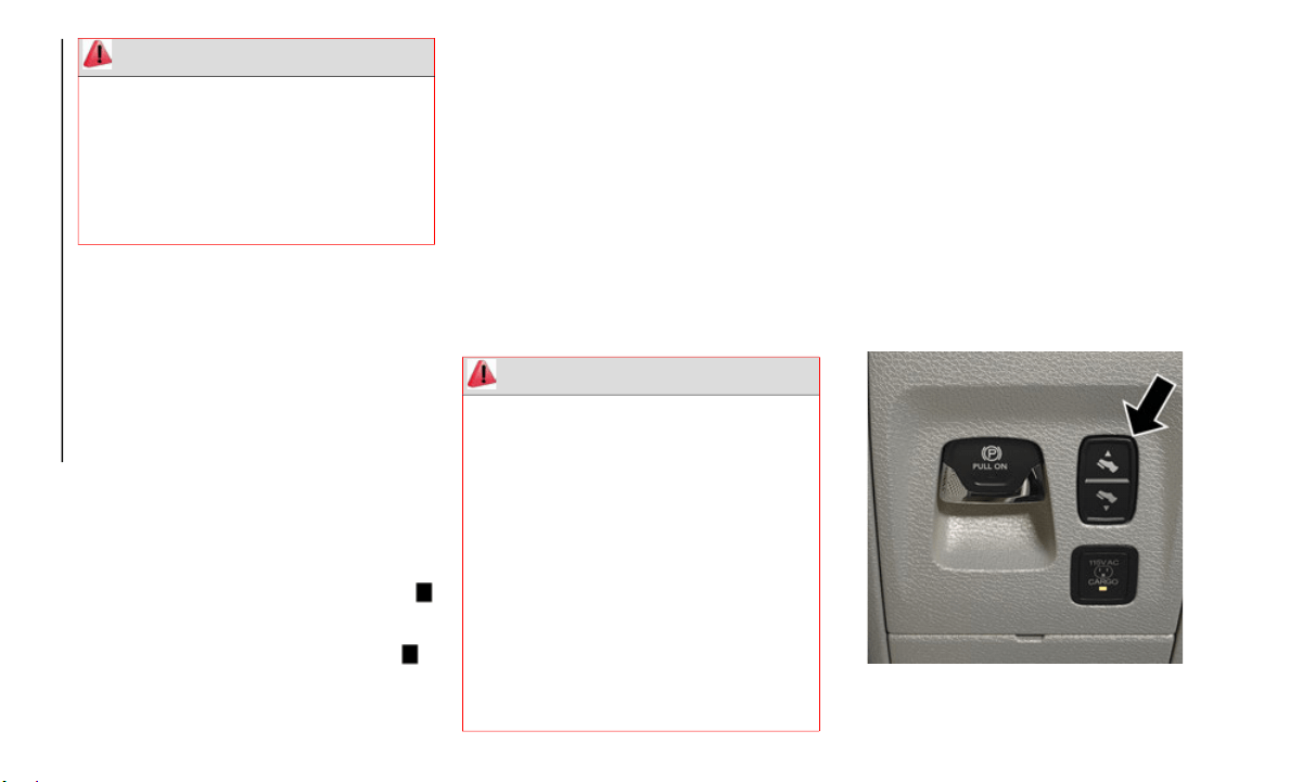
Rear Heated Seats
On some models, the two outboard rear seats
are equipped with heated seats. The heated
seat switches for these seats are located on
the rear of the center console.
There are two heated seat switches that allow
the rear
passengers to operate the seats
independently. You can choose from HI,
MED, LO, or OFF heat settings. Amber indi
-
cator lights in each switch indicate the level
of heat i
n use.
Push the heated seat button once to
turn the HI setting on.
Push the heated seat button a second
time to turn the MED setting on.
Push the heated seat button a third
time to turn the LO setting on.
Push the heated seat button a fourth
time to turn the heating elements off.
NOTE:
The level of heat selected will stay on until
the operator changes it.
Once a heat setting is selected, heat will
be felt within two to five minutes.
The engine must be running for the heated
seats to operate.
WARNING!
Persons who are unable to feel pain to
the skin because of advanced age,
chronic illness, diabetes, spinal cord
injury, medication, alcohol use, exhaus
-
tion or other physical condition must
exercise
care when using the seat heater.
It may cause burns even at low tempera
-
tures, especially if used for long periods
of time.
Do not place anything on the seat or
seatback that insulates against heat,
such as a blanket or cushion. This may
cause the seat heater to overheat. Sitting
in a seat that has been overheated could
cause serious burns due to the increased
surface temperature of the seat.

23
Ventilated Seats — If Equipped
Front Ventilated Seats
Located in the seat cushion are small fans
that draw the air from the passenger
compartment and move air through fine
perforations in the seat cover to help keep
the driver and front passenger cooler in
higher ambient temperatures. The fans
operate at three speeds, HI, MED and LO.
The front ventilated seats control buttons are
located on
the center instrument panel
below the touchscreen, and are also located
within the climate or controls screen of the
touchscreen.
Press the ventilated seat button once to
choose HI.
Press the ventilated seat button a
second time to choose MED.
Press the ventilated seat button a third
time to choose LO.
Press the ventilated seat button a
fourth time to turn the ventilation off.
NOTE:
The engine must be running for the venti-
lated seats to operate.
Vehicles Equipped With Remote Start
On models that are equipped with remote
s
tart, the
ventilated seats can be
programmed to come on during a remote
start.
This feature can be programmed through the
Uconnect s
ystem. Refer to “Uconnect
Settings” in “Multimedia” in your Owner’s
Manual for further information.
Rear Ventilated Seats
On some models, the two outboard rear seats
are equipped with ventilated seats. The rear
ventilated seat control switches are located on
the rear of the center console.
There are two ventilated seat switches that
allow the
rear passengers to operate the seats
independently. The fans operate at three
speeds: HI, MED, and LO.
Push the ventilated seat button once to
choose HI.
Push the ventilated seat button a second
time to choose MED.
Push the ventilated seat button a third
time to choose LO.
Push the ventilated seat button a fourth
time to turn the ventilated seat off.
NOTE:
The engine must be running for the ventilated
s
eats to o
perate.
HEAD RESTRAINTS
Head restraints are designed to reduce the risk
of injury by restricting head movement in the
event of a rear impact. Head restraints should
be adjusted so that the top of the head restraint
is located above the top of your ear.
NOTE:
Do not reverse the head restraints (making
the rear o
f the head restraint face forward) in
an attempt to gain additional clearance to
the back of your head.
WARNING!
All occupants, including the driver, should
not operate a vehicle or sit in a vehicle’s
seat until the head restraints are placed in
their proper positions in order to minimize
the risk of neck injury in the event of a
crash.
Head restraints should never be adjusted
while the vehicle is in motion. Driving a
vehicle with the head restraints improperly
adjusted or removed could cause serious
injury or death in the event of a collision.
GETTING TO KNOW YOUR VEHICLE
24
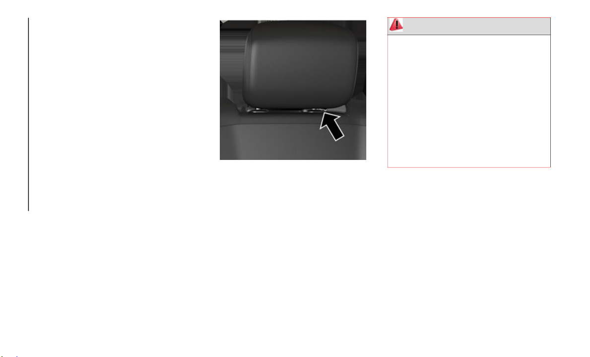
Front Head Restraints
Your vehicle is equipped with front four way
driver and passenger head restraints.
To raise the head restraint, pull upward on
the head
restraint. To lower the head
restraint, push the adjustment button,
located at the base of the head restraint, and
push downward on the head restraint.
To adjust the head restraint forward, pull the
top of th
e head restraint toward the front of
the vehicle as desired and release. To adjust
the head restraint rearward, pull the top of
the head restraint to the forward most posi
-
tion and release. The head restraint will
return to
the rear most position.
NOTE:
If your vehicle is equipped with a front bench
s
eat, the
center head restraint is not adjust-
able or removable.
Head Restraint Adjustment Button
NOTE:
The head restraints should only be removed
b
y qualif
ied technicians, for service
purposes only. If either of the head restraints
require removal, see an authorized dealer.
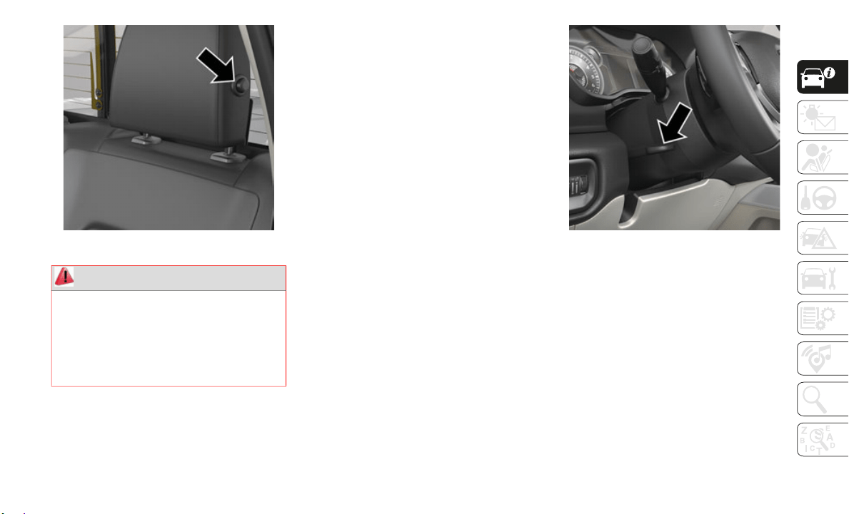
Rear Head Restraints
The outboard head restraints are non-adjust-
able, but can be folded down for improved
rearward
visibility. Push the button on the
outboard side of the head restraint to
release. To return the head restraint to its
upright position, push up on the head
restraint until it locks back into place.
WARNING!
All occupants, including the driver,
should not operate a vehicle or sit in a
vehicle’s seat until the head restraints
are placed in their proper positions in
order to minimize the risk of neck injury
in the event of a crash.
Head restraints should never be adjusted
while the vehicle is in motion. Driving a
vehicle with the head restraints improp
-
erly adjusted or removed could cause
serious i
njury or death in the event of a
collision.
25
Release Button
The center head restraint is not adjustable or
removable.
N
OTE:
The head restraints should only be removed
b
y qualifi
ed technicians, for service
purposes only. If any of the head restraints
require removal, see an authorized dealer.
For child restraint tethering, refer to “Occu-
pant Restraint Systems” in “Safety” for
further in
formation.
STEERING WHEEL
Tilt/Telescoping Steering Column
This feature allows you to tilt the steering
column upward or downward. It also allows
you to lengthen or shorten the steering
column. The tilt/telescoping lever is located
on the steering column, below the multifunc
-
tion lever.
Tilt/Telescoping Lever
To unlock the steering column, push the
l
ever down
ward. To tilt the steering column,
move the steering wheel upward or down
-
ward as desired. To lengthen or shorten the
steering c
olumn, pull the steering wheel
outward or push it inward as desired. To lock
the steering column into position, push the
lever upward until fully engaged.
WARNING!
Sitting in a seat with the head restraint in
its lowered position could result in serious
injury or death in a collision. Always make
sure the outboard head restraints are in
their upright positions when the seat is to
be occupied.
GETTING TO KNOW YOUR VEHICLE
26
Heated Steering Wheel — If Equipped
The steering wheel contains a heating element
that helps warm your hands in cold weather.
The heated steering wheel has only one
temperature setting. Once the heated steering
wheel has been turned on, it will stay on until
the operator turns it off. The heated steering
wheel may not turn on when it is already warm.
The heated steering wheel control button is
located on
the center instrument panel below
the touchscreen, as well as within the climate
or controls screen of the touchscreen.
Press the heated steering wheel button
once to turn the heating element on.
Press the heated steering wheel button a
second time to turn the heating element off.
NOTE:
The engine must be running for the heated
steering w
heel to operate.
Vehicles Equipped With Remote Start
On models that are equipped with remote
s
tart, the
heated steering wheel can be
programmed to come on during a remote
start.
This feature can be programmed through the
Uconnect s
ystem. Refer to “Uconnect
Settings” in “Multimedia” in the Owner’s
Manual for further information.
DRIVER ADJUSTABLE
PEDALS — IF EQUIPPED
The adjustable pedals system is designed to
allow a greater range of driver comfort for
steering wheel tilt and seat position. This
feature allows the brake and accelerator pedals
to move toward or away from the driver to
provide improved position with the steering
wheel.
The adjustable pedal switch is located on the
instrument
panel, below the headlight switch.
Adjustable Pedals Switch
WARNING!
Do not adjust the steering column while
driving. Adjusting the steering column
while driving or driving with the steering
column unlocked, could cause the driver
to lose control of the vehicle. Failure to
follow this warning may result in serious
injury or death.
WARNING!
Persons who are unable to feel pain to
the skin because of advanced age,
chronic illness, diabetes, spinal cord
injury, medication, alcohol use, exhaus
-
tion, or other physical conditions must
exercise c
are when using the steering
wheel heater. It may cause burns even at
low temperatures, especially if used for
long periods.
Do not place anything on the steering
wheel that insulates against heat, such
as a blanket or steering wheel covers of
any type and material. This may cause
the steering wheel heater to overheat.
27
The pedals can be adjusted with the igni-
tion OFF.
The pedals cannot be adjusted when the
vehicle is in REVERSE or when the Speed
Control System or Adaptive Cruise Control
systems are on. The following messages
will appear on vehicles equipped with an
instrument cluster display if the pedals
are attempted to be adjusted when the
system is locked out: “Adjustable Pedal
Disabled — Cruise Control Engaged” or
“Adjustable Pedal Disabled — Vehicle In
Reverse”.
NOTE:
Always adjust the pedals to a position that
allows full pedal travel.
Further small adjustments may be neces-
sary to find the best possible seat/pedal
position.
For vehicles equipped with Driver Memory
Seat, you can use your key fob or the
memory switch on the driver’s door trim
panel to return the adjustable pedals to
pre-programmed positions.
Refer to “Driver Memory Seat” in “Getting
To Know Your Vehicle” for further informa-
tion.
MIRRORS
Tilt Side Mirrors In Reverse — If Equipped
Tilt Side Mirrors In Reverse provides auto-
matic outside mirror positioning which will
aid the d
river’s view of the ground rearward
of the front doors. The outside mirrors will
move slightly downward from the present
position when the vehicle is shifted into
REVERSE. The outside mirrors will then
return to the original position when the
vehicle is shifted out of the REVERSE posi
-
tion. Each stored memory setting will have
a
n associ
ated Tilt Side Mirrors In Reverse
position.
NOTE:
The Tilt Side Mirrors In Reverse feature is
n
ot turne
d on when delivered from the
factory.
This feature can be programmed through the
Uconnect
system. Refer to “Uconnect
Settings” in “Multimedia” in the Owner’s
Manual for further information.
Power Folding Outside Mirrors For
Standard And Trailer Tow — If Equipped
If equipped with power folding mirrors, they
can be electrically folded rearward and
unfolded into the drive position.
The switch for the power folding mirrors is
located b
etween the power mirror switches L
(left) and R (right). Push the switch once and
the mirrors will fold in, push the switch a
second time and the mirrors will return to the
normal driving position.
If the mirror is manually folded after electri-
cally cycled, a potential extra button push is
required
to get the mirrors back to the home
position. If the mirror does not electrically
fold, check for ice or dirt build up at the pivot
area which can cause excessive drag.
WARNING!
Do not adjust the pedals while the vehicle is
moving. You could lose control and have an
accident. Always adjust the pedals while the
vehicle is parked.
CAUTION!
Do not place any article under the adjustable
pedals or impede its ability to move, as it
may cause damage to the pedal controls.
Pedal travel may become limited if
movement is stopped by an obstruction in
the adjustable pedal's path.
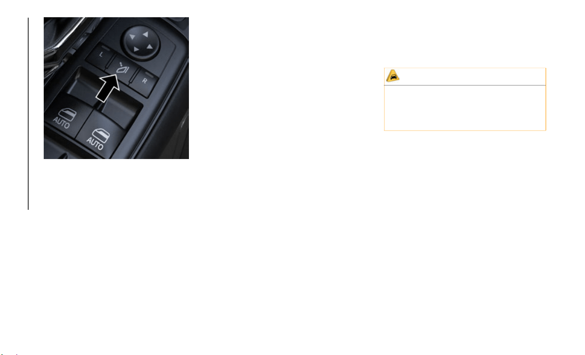
GETTING TO KNOW YOUR VEHICLE
28
Power Folding Mirror Switch
Resetting The Power Folding Outside Mirrors
You may need to reset the power folding
m
irrors i
f the following occurs:
The mirrors are accidentally blocked while
folding.
The mirrors are accidentally manually
folded/unfolded.
The mirrors come out of the unfolded posi-
tion.
The mirrors shake and vibrate at normal
driving speeds.
To Reset The Power Folding Mirrors:
1. Using the power folding mirror switch,
move the
mirror to its normal driving
(home) position.
2. Using the power folding mirror switch,
move the
mirror to the full retract posi-
tion (this may require multiple button
p
ushes).
This resets them to their normal
position.
NOTE:
The power fold mirrors are designed to
operate while the vehicle is stationary or
traveling at moderate speeds. If you
attempt to power fold the mirrors at high
speeds they may not fully open or close.
You should slow down to a moderate speed
and complete the operation.
When pushing the power fold button 10 or
more times in one minute the system
shuts down for one minute to protect the
motors from over heating.
Outside Mirrors Folding Feature
All outside mirrors are designed to be able to
be manually folded both forward and rear-
ward to prevent damage.
EXTERIOR LIGHTS
Headlight Switch
The headlight switch is located on the left
side of the instrument panel. This switch
controls the operation of the headlights,
parking lights, automatic headlights — if
equipped, instrument panel light dimming,
cargo light — if equipped, and fog lights —
if equipped.
CAUTION!
It is recommended to fold the mirrors into
the full rearward position to resist damage
when entering a car wash or a narrow
location.
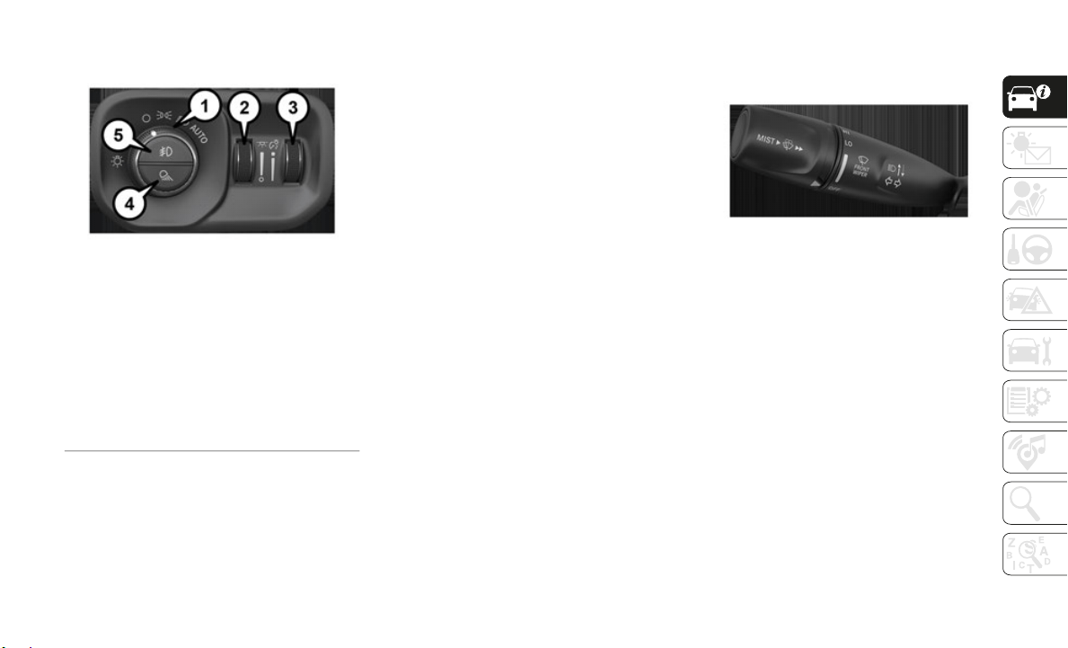
29
Headlight Switch
Rotate the headlight switch clockwise to the
first det
ent for parking light and instrument
panel light operation. Rotate the headlight
switch to the second detent for headlight,
parking light, and instrument panel light
operation.
Daytime Running Lights (DRL) — If
Equipped
The headlights on your vehicle will illumi-
nate when the engine is started and the
transmiss
ion is in any gear except PARK.
This provides a constant "lights on" condition
until the ignition is turned OFF. The lights
illuminate at less than half of normal inten
-
sity. If the parking brake is applied, the
Daytime R
unning Lights (DRL) will turn off.
Also, if a turn signal is activated, the DRL
lamp on the same side of the vehicle may
turn off for the duration of the turn signal
activation. Once the turn signal is no longer
active, the DRL lamp will illuminate.
NOTE:
If allowed by law in the country in which the
vehicle w
as purchased, the Daytime Running
Lights can be turned on and off using the
Uconnect System, refer to “Uconnect
Settings” in “Multimedia” in the Owner’s
Manual for further information.
Multifunction Lever
The multifunction lever is located on the left
side of the steering column.
Multifunction Lever
High/Low Beam Switch
Push the multifunction lever toward the
instrument panel to switch the headlights to
high beam. Pulling the multifunction lever
back toward the steering wheel will turn the
low beams back on, or shut the high beams
off.
Automatic High Beam Headlamp Control
— If Equipped
The Automatic High Beam Headlamp Control
system provides increased forward lighting at
night by automating high beam control
through the use of a digital camera mounted
1 — Rotate Head-
light Controls
4 — Cargo/Bed Light
Switch
2 —
Ambient Light
Dimmer
5 —
Front Fog Light
Switch
3 — Instrument Pan-
el Dimmer

GETTING TO KNOW YOUR VEHICLE
30
on the inside rearview mirror or a windshield
mounted camera. These cameras detect
vehicle specific light and automatically
switch from high beams to low beams until
the approaching vehicle is out of view.
NOTE:
The Automatic High Beam Headlamp
Control can be turned on or off by
selecting “ON” under “Auto Dim High
Beams” within your Uconnect settings, as
well as turning the headlight switch to the
AUTO position. Refer to “Uconnect
Settings” in “Multimedia” in your Owner’s
Manual for further information.
Broken, muddy, or obstructed headlights
and taillights of vehicles in the field of
view will cause headlights to remain on
longer (closer to the vehicle). Also, dirt,
film, and other obstructions on the wind
-
shield or camera lens will cause the
system to
function improperly.
To opt out of Advanced Auto High Beam
Sensitivity Control in the rearview mirror
(default setting) and enter Reduced High
Beam Sensitivity Control (not recom
-
mended), turn the ignition ON and toggle
t
he high
beam lever six full on/off cycles
within ten seconds. The system will return
to the default setting once the ignition is
turned OFF.
If the windshield or Automatic High Beam
Headlamp
Control mirror is replaced, the
mirror must be re-aimed to ensure proper
performance. See a local authorized dealer.
To Activate
1. The Automatic High Beams are enabled
through the Uconnect system. Refer to
“Uconnect Settings” in “Multimedia” in
the Owner’s Manual for further informa
-
tion.
2. Turn the headlight switch to the AUTO
headligh
t position.
3. Push the multifunction lever away from
you (tow
ard front of vehicle) to engage
the high beam mode.
NOTE:
The Automatic High Beams will not activate
until the
vehicle is at or above 12 mph
(20 km/h).
To Deactivate
1. Pull the multifunction lever toward you
(or rearward in vehicle) to manually deac-
tivate the system (normal operation of
l
ow beams
).
2. Push back on the multifunction lever to
reactiva
te the system.
The Automatic High Beams can also be
deactivat
ed through the Uconnect system.
Refer to “Uconnect Settings” in “Multi
-
media” in the Owner’s Manual for further
informati
on.
Flash-To-Pass
You can signal another vehicle with your
headlights by lightly pulling the multifunc-
tion lever toward you. This will cause the
h
igh beam
headlights to turn on, and remain
on, until the lever is released.
Automatic Headlights
This system automatically turns your head-
lights on or off based on ambient light levels.
To turn t
he system on, turn the headlight
switch to the extreme clockwise position
aligning the indicator with the AUTO on the
headlight switch. When the system is on, the
Headlight Time Delay feature is also on. This
means your headlights will stay on for up to
90 seconds after you turn the ignition switch
OFF. To turn the Automatic System off, turn
the headlight switch counterclockwise to the
O (off) position.
NOTE:
The engine must be running before the head-
lights will come on in the Automatic mode.
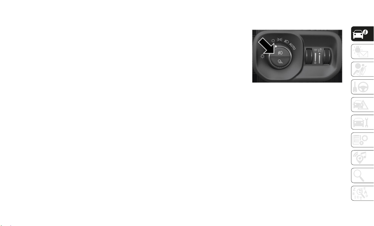
31
Parking Lights And Panel Lights
To turn on the parking lights and instrument
panel lights, from the O (off) position, rotate
the headlight switch clockwise to the first
detent. To turn off the parking lights, rotate
the headlight switch back to the O (off) posi
-
tion.
Headlights On With Wipers (Available
With Automatic Headlights Only)
When this feature is active, the headlights
will turn on approximately 10 seconds after
the wipers are turned on if the headlight
switch is placed in the AUTO position. In
addition, the headlights will turn off when
the wipers are turned off, if they were turned
on by this feature.
NOTE:
This feature can be programmed through the
Uconnect
system. Refer to “Uconnect
Settings” in “Multimedia” in the Owner’s
Manual for further information.
Headlight Delay
To aid in your exit, your vehicle is equipped
with a headlight delay that will leave the
headlights on for approximately up to 90
seconds. This delay is initiated when the
ignition is turned off while the headlight
switch is on, and then the headlight switch is
cycled off. Headlight delay can be canceled
by either turning the headlight switch on
then off, or by turning the ignition to the ON/
RUN position.
NOTE:
This feature can be programmed through the
Uconnect
system. Refer to “Uconnect
Settings” in “Multimedia” in the Owner’s
Manual for further information.
Lights-On Reminder
If the headlights, parking lights, or cargo
lights are left on after the ignition is turned
OFF, a chime will sound when the driver’s
door is opened.
Front Fog Lights — If Equipped
To activate the front fog lights, turn on the
parking lights or low beam headlights and
push in the center of the headlight switch
control knob. Pushing the headlight switch
control knob a second time will turn the front
fog lights off.
Front Fog Light Switch
Turn Signals
Move the multifunction lever up or down and
the arrows on each side of the instrument
cluster display will flash to show proper oper
-
ation of the front and rear turn signal lights.
NOTE:
If either light remains on and does not flash,
or there
is a very fast flash rate, check for a
defective outside light bulb. If an indicator
fails to light when the lever is moved, it
would suggest that the indicator bulb is
defective.
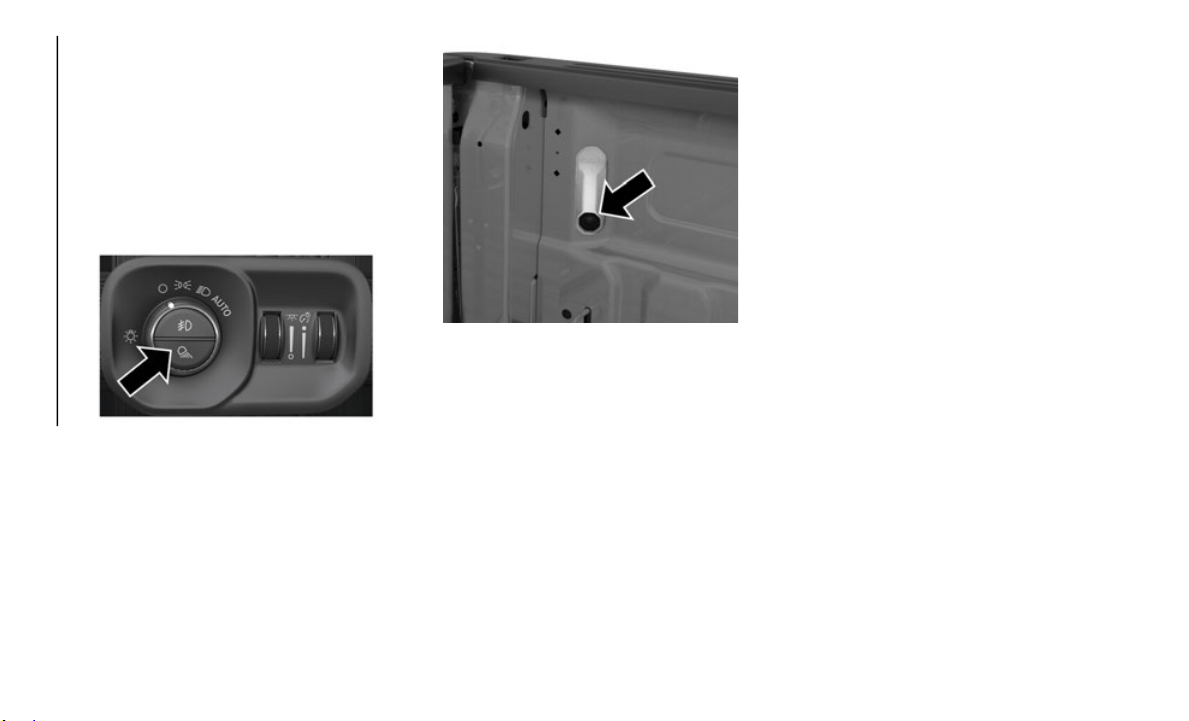
GETTING TO KNOW YOUR VEHICLE
32
Cargo Light With Bed Lights — If
Equipped
The cargo light and bed lights (if equipped)
are turned on by pushing the cargo lights
button located on the lower half of the head
-
light switch.
Cargo/Bed Lights Button On Headlight Switch
If the vehicle’s speed is 0 mph (0 km/h),
t
hese lig
hts can also be turned on using the
switch located just inside the pickup box, on
the lower part of the bed light lens. A telltale
will illuminate in the instrument cluster
display when these lights are on. Pushing the
switch a second time will turn the lights off.
Bed Light Switch In Truck Bed
The cargo light and bed lights (if equipped)
w
ill turn
on for approximately 30 seconds
when a key fob unlock button is pushed, as
part of the Illuminated Entry feature.
NOTE:
For vehicles shipped to or sold in the states
of Califo
rnia or Mississippi, the Cargo, Bed,
and Mirror Spotter lights will not work while
the vehicle is in motion. In every other state,
the Cargo and Mirror Spotter lights will turn
off when the vehicle is in motion, but the
Bed Light will remain on. In all states,
including California and Mississippi, if a bed
camera is deactivated, the Bed Lights will
turn back on.
Battery Saver
To protect the life of your vehicle’s battery,
load shedding is provided for both the inte-
rior and exterior lights.
If the ignition is OFF, the interior lights will
a
utomatic
ally turn off when:
Any door is left ajar for 10 minutes.
The Dome Defeat button is pushed.
The Cargo, Bed, and Spotter lights are
manually activated by either the headlight
switch or the truck bed switch.
NOTE:
Battery saver mode is canceled if the ignition
is ON.
If t
he headlights remain on while the ignition
is cycled
OFF, the exterior lights will auto-
matically turn off after eight minutes. If the
h
eadlight
s are turned on and left on for eight
minutes while the ignition is OFF, the exte
-
rior lights will automatically turn off.
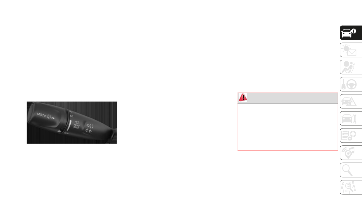
33
WINDSHIELD WIPERS AND
WASHERS
Windshield Wipers
The wipers and washers are operated by a
switch in the multifunction lever. Turn the
end of the lever to select the desired wiper
speed.
Windshield Wiper/Washer Switch
Rotate the end of the lever upward, to the
f
irst dete
nt past the intermittent settings for
low-speed wiper operation. Rotate the end of
the lever upward to the second detent past
the intermittent settings for high-speed
wiper operation.
Intermittent Wiper System
The intermittent feature of this system was
designed for use when weather conditions
make a single wiping cycle, with a variable
pause between cycles, desirable. For
maximum delay between cycles, rotate the
control knob upward to the first detent.
The delay interval decreases as you rotate
the knob u
ntil it enters the low continual
speed position. The delay can be regulated
from a maximum of about 18 seconds
between cycles, to a cycle every one second.
The delay intervals will double in duration
when the vehicle speed is 10
mph (16 km/h)
or less.
Windshield Washers
To use the windshield washer, push the
washer knob, located on the end of the multi-
function lever, inward and hold. Washer fluid
w
ill be sp
rayed and the wiper will operate for
two to three cycles after the washer knob is
released.
If the washer knob is depressed while in the
delay rang
e, the wiper will operate for several
seconds after the washer knob is released. It
will then resume the intermittent interval
previously selected. If the washer knob is
pushed while in the off position, the wiper
will turn on and cycle approximately three
times after the wash knob is released.
To prevent freeze-up of your windshield
washer sys
tem in cold weather, select a solu-
tion or mixture that meets or exceeds the
t
emperatur
e range of your climate. This
rating information can be found on most
washer fluid containers.
Mist Feature
When a single wipe to clear off road mist or
spray from a passing vehicle is needed, push
the washer knob, located on the end of the
multifunction lever, inward briefly and
release. The wipers will cycle one time and
automatically shut off.
WARNING!
Sudden loss of visibility through the
windshield could lead to a collision. You
might not see other vehicles or other
obstacles. To avoid sudden icing of the
windshield during freezing weather, warm
the windshield with the defroster before
and during windshield washer use.

GETTING TO KNOW YOUR VEHICLE
34
NOTE:
The mist feature does not activate the
washer pu
mp; therefore, no washer fluid will
be sprayed on the windshield. The wash
function must be used in order to spray the
windshield with washer fluid.
Rain Sensing Wipers — If Equipped
This feature senses rain and snowfall on the
windshield and automatically activates the
wipers for the driver. The feature is espe
-
cially useful for road splash or overspray from
the winds
hield washers of the vehicle ahead.
Rotate the end of the multifunction lever to
one of four settings to activate this feature.
NOTE:
This feature can be programmed through the
Uconnect
system. Refer to “Uconnect
Settings” in “Multimedia” in your Owner’s
Manual for further information.
The sensitivity of the system can be adjusted
with the
multifunction lever. Wiper delay
position 1 is the least sensitive, and wiper
delay position 4 is the most sensitive.
NOTE:
Position 3 should be used for normal rain
condition
s.
Positions 1 and 2 can be used if the driver
desires l
ess wiper sensitivity. Position 4 can
be used if the driver desires more sensitivity.
Place the wiper switch in the O (off) position
when not using the system.
NOTE:
The Rain Sensing feature will not operate
when the wiper switch is in the low or
high-speed position.
The Rain Sensing feature may not func-
tion properly when ice, or dried salt water
is presen
t on the windshield.
Use of Rain-X or products containing wax
or silicone may reduce Rain Sensing
performance.
The Rain Sensing system has protection
features
for the wiper blades and arms, and
will not operate under the following condi
-
tions:
Low Ambient Temperature — When the igni-
tion is first turned ON, the Rain Sensing
system wi
ll not operate until the wiper
switch is moved, vehicle speed is greater
than 0
mph (0 km/h), or the outside
temperatu
re is greater than 32°F (0°C).
Transmission In NEUTRAL Position — When
the ignition is ON, and the transmission is
in the NEUTRAL position, the Rain
Sensing system will not operate until the
wiper switch is moved, vehicle speed is
greater than 3
mph (5 km/h), or the gear
selector
is moved out of the NEUTRAL
position.
Remote Start Mode Inhibit — On vehicles
equipped with Remote Starting system,
Rain Sensing wipers are not operational
when the vehicle is in the remote start
mode. Once the operator is in the vehicle
and has placed the ignition switch in the
RUN position, Rain Sensing wiper opera
-
tion can resume, if it has been selected,
and no ot
her inhibit conditions
(mentioned previously) exist.
CLIMATE CONTROLS
The Climate Control System allows you to
regulate the temperature, air flow, and direc-
tion of air circulating throughout the
v
ehicle. T
he controls are located on the
touchscre
en (if equipped), on the sides of
the touchscreen, or on the instrument panel
below the radio.
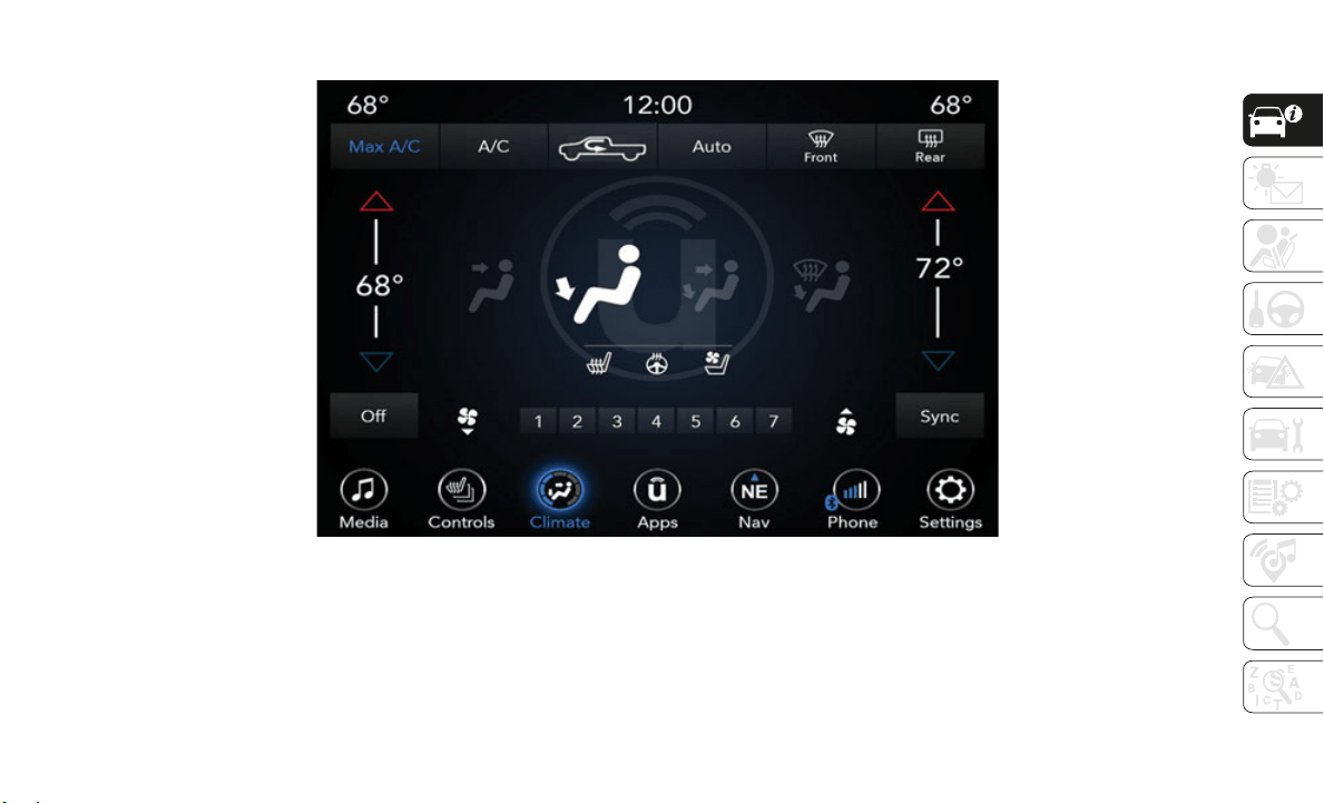
35
Climate Controls With A Touchscreen Overview
Uconnect 4/4C/4C NAV With 8.4–inch Display Automatic Climate Controls
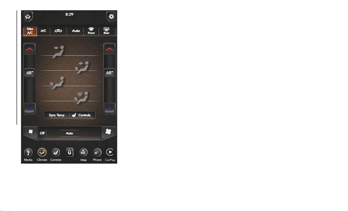
GETTING TO KNOW YOUR VEHICLE
36
Uconnect 4C NAV With 12–inch Display
Automatic Climate Controls
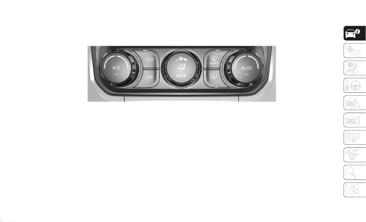
37
Uconnect 4C/4C NAV With 8.4–inch Display Automatic Climate Control Knobs

GETTING TO KNOW YOUR VEHICLE
38
Control Descriptions
NOTE:
Icons and descriptions can vary based upon vehicle equipment.
Icon Description
MAX A/C
Press and release to change the current setting, the indicator illuminates when MAX A/C is on. Performing this
function
again will cause the MAX A/C operation to switch into manual mode and the MAX A/C indicator will turn
off.
NOTE:
The MAX A/C button is only available on the touchscreen.
A/C Control Knob
A/C Button
A/C Button
Press and release the button on the touchscreen, or push and release the button on the faceplate, to change the
current s
etting, the indicator illuminates when A/C is on.
Recirculation Button
Press and release this button to change the system between recirculation mode and outside air mode.
Recircula
tion can be used when outside conditions such as smoke, odors, dust, or high humidity are present.
Recirculation can be used in all modes. Recirculation may be unavailable (button on the touchscreen greyed out)
if conditions exist that could create fogging on the inside of the windshield. The A/C can be deselected manually
without disturbing the mode control selection. Continuous use of the Recirculation mode may make the inside air
stuffy and window fogging may occur. Extended use of this mode is not recommended.

39
AUTO Control Knob
AUTO Button
AUTO
Automatically controls the interior cabin temperature by adjusting airflow distribution and amount. Toggling this
function
will cause the system to switch between manual mode and automatic modes.
Refer to “Automatic Operation” within this section for more information.
Front Defrost Button
Press and release the touchscreen button, or push and release the button on the faceplate, to change the current
airflow s
etting to Defrost mode. The indicator illuminates when this feature is on. Air comes from the windshield
and side window demist outlets. When the defrost button is selected, the blower level may increase. Use Defrost
mode with maximum temperature settings for best windshield and side window defrosting and defogging. When
toggling the front defrost mode button, the climate system will return to previous setting.
Rear Defrost Button
Press and release the button on the touchscreen, or push and release the button on the faceplate, to turn on the
rear wind
ow defroster and the heated outside mirrors (if equipped). An indicator will illuminate when the rear
window defroster is on. The rear window defroster automatically turns off after ten minutes.
Driver and Passenger Temperature Up and Down Buttons
Provides the driver and passenger with independent temperature control. Push the red button on the faceplate or
touchscre
en or press and slide the temperature bar towards the red arrow button on the touchscreen for warmer
temperature settings. Push the blue button on the faceplate or touchscreen or press and slide the temperature bar
towards the blue arrow button on the touchscreen for cooler temperature settings.
NOTE:
The numbers within the temperature display will only appear if the system is equipped with an automatic climate
control s
ystem.
Icon Description

GETTING TO KNOW YOUR VEHICLE
40
SYNC
Press the SYNC button on the touchscreen to toggle the SYNC feature on/off. The SYNC indicator is illuminated
when this
feature is enabled. SYNC is used to synchronize the passenger temperature setting with the driver
temperature setting. Changing the passenger’s temperature setting while in SYNC will automatically exit this
feature.
NOTE:
The SYNC button is only available on the touchscreen.
Blower Control Knob
Blower Control Buttons
Blower Control
Blower Control is used to regulate the amount of air forced through the climate system. There are seven blower
speeds av
ailable. Adjusting the blower will cause automatic mode to switch to manual operation. The speeds can
be selected using either the blower control knob on the faceplate or the buttons on the touchscreen.
Faceplate: The blower speed increases as you turn the blower control knob clockwise from the lowest blower
setting. The blower speed decreases as you turn the blower control knob counterclockwise.
Touchscreen: Use the small blower icon to reduce the blower setting and the large blower icon to increase the
blower setting. Blower can also be selected by pressing the blower bar area between the icons.
NOTE:
On Uconnect 4C NAV With 12–inch display radios, pressing the blower control button below one turns the Climate Control
s
ystem OF
F.
Mode Control Knob
Mode Controls Button
Modes Control
Control Knob: Push the
Mode Control Knob to change the airflow distribution mode. The airflow distribution mode
can be adjusted so air comes from the instrument panel outlets, floor outlets, defrost outlets and demist outlets.
Touchscreen: Select M
ode by pressing one of the Mode buttons on the touchscreen to change the airflow
distribution mode. The airflow distribution mode can be adjusted so air comes from the instrument panel outlets,
floor outlets, defrost outlets and demist outlets.
Icon Description
41
Panel Mode Panel Mode
Air comes from the outlets in the instrument panel. Each of these outlets can be individually adjusted to direct the
flow of a
ir. The air vanes of the center outlets and outboard outlets can be moved up and down or side to side to
regulate airflow direction. There is a shut off wheel located below the air vanes to shut off or adjust the amount of
airflow from these outlets.
Bi-Level Mode Bi-Level Mode
Air comes from the instrument panel outlets and floor outlets. A slight amount of air is directed through the
d
efrost a
nd side window demister outlets.
NOTE:
Bi-Level mode is designed under comfort conditions to provide cooler air out of the panel outlets and warmer air
f
rom the
floor outlets.
Floor Mode Floor Mode
Air comes from the floor outlets. A slight amount of air is directed through the defrost and side window demister
outlets.
Mi
x Mode Mix Mode
Air is directed through the floor, defrost, and side window demister outlets. This setting works best in cold or
snowy con
ditions that require extra heat to the windshield. This setting is good for maintaining comfort while
reducing moisture on the windshield.
Climate Control OFF Button
This button turns the Climate Control System off.
Icon Description

GETTING TO KNOW YOUR VEHICLE
42
Climate Control Functions
A/C (Air Conditioning)
The Air Conditioning (A/C) button allows the
operator to manually activate or deactivate
the air conditioning system. When the air
conditioning system is turned on, cool dehu
-
midified air will flow through the outlets into
t
he cabin
. For improved fuel economy, press
the A/C button to turn off the air conditioning
and manually adjust the blower and airflow
mode settings. Also, make sure to select only
Panel, Bi-Level, or Floor modes.
NOTE:
For Manual Climate Controls, if the system
is in Mix, Floor or Defrost Mode, the A/C
can be turned off, but the A/C system shall
remain active to prevent fogging of the
windows.
If fog or mist appears on the windshield or
side glass, select Defrost mode, and
increase blower speed if needed.
If your air conditioning performance
seems lower than expected, check the
front of the A/C condenser (located in front
of the radiator), for an accumulation of dirt
or insects. Clean with a gentle water spray
from the front of the radiator and through
the condenser.
MAX A/C
MAX A/C sets the control for maximum
c
ooling p
erformance.
Press and release to toggle between MAX A/C
and the p
rior settings. The button illuminates
when MAX A/C is on.
In MAX A/C, the blower level and mode position
can be ad
justed to desired user settings.
Pressing other settings will cause the MAX A/C
operation to switch to the selected setting and
MAX A/C to exit.
Recirculation
In cold weather, use of Recirculation mode
may lead to excessive window fogging. The
Recirculation feature may be unavailable
(button on the touchscreen greyed out) if
conditions exist that could create fogging on
the inside of the windshield.
Automatic Temperature Control (ATC)
Automatic Operation
1. Push the AUTO button on the faceplate,
or the AUTO button on the touchscreen
on the Automatic Temperature Control
(ATC) Panel.
2. Next, adjust the temperature you would
like the
system to maintain by adjusting
the driver and passenger temperature
control buttons. Once the desired
temperature is displayed, the system will
achieve and automatically maintain that
comfort level.
3. When the system is set up for your
comfort
level, it is not necessary to
change the settings. You will experience
the greatest efficiency by simply allowing
the system to function automatically.
NOTE:
It is not necessary to move the tempera-
ture settings for cold or hot vehicles. The
system au
tomatically adjusts the tempera-
ture, mode, and blower speed to provide
c
omfort a
s quickly as possible.
The temperature can be displayed in U.S.
or Metric units by selecting the US/Metric
customer-programmable feature. Refer to
the “Uconnect Settings” in “Multimedia”
in your Owner’s Manual for further infor
-
mation.
To provide you with maximum comfort in the
A
utomatic
mode during cold start-ups, the
blower fan will remain on low until the
engine warms up. The blower will increase in
speed and transition into Auto mode.
43
(Continued)
Manual Operation Override
This system offers a full complement of
manual override features. The AUTO symbol
in the front ATC display will be turned off
when the system is being used in the manual
mode.
Operating Tips
Summer Operation
The engine cooling system must be
protected with a high-quality antifreeze
coolant to provide proper corrosion protec
-
tion and to protect against engine over-
heating. OAT coolant (conforming to
MS.90032)
is recommended.
Winter Operation
To ensure the best possible heater and
defroster performance, make sure the engine
cooling system is functioning properly and
the proper amount, type, and concentration
of coolant is used. Use of the Air Recircula
-
tion mode during Winter months is not
recommende
d, because it may cause window
fogging.
Vacation/Storage
Before you store your vehicle, or keep it out
of service (i.e., vacation) for two weeks or
more, run the air conditioning system at idle
for about five minutes, in fresh air with the
blower setting on high. This will ensure
adequate system lubrication to minimize the
possibility of compressor damage when the
system is started again.
Window Fogging
Vehicle windows tend to fog on the inside in
mild, rainy, and/or humid weather. To clear
the windows, select Defrost or Mix mode and
increase the front blower speed. Do not use
the Recirculation mode without A/C for long
periods, as fogging may occur.
Outside Air Intake
Make sure the air intake, located directly in
front of the windshield, is free of obstruc-
tions, such as leaves. Leaves collected in the
a
ir intake
may reduce airflow, and if they
enter the plenum, they could plug the water
drains. In Winter months, make sure the air
intake is clear of ice, slush, and snow.
Cabin Air Filter
The climate control system filters out dust
and pollen from the air. Contact an autho-
rized dealer to service your cabin air filter,
a
nd to hav
e it replaced when needed.
CAUTION!
Failure to follow these cautions can cause
damage to the heating elements:
Use care when washing the inside of the
rear window. Do not use abrasive window
cleaners on the interior surface of the
window. Use a soft cloth and a mild
washing solution, wiping parallel to the
heating elements. Labels can be peeled
off after soaking with warm water.
Do not use scrapers, sharp instruments,
or abrasive window cleaners on the inte-
rior surface of the window.
Keep all objects a safe distance from the
window.
CAUTION! (Continued)
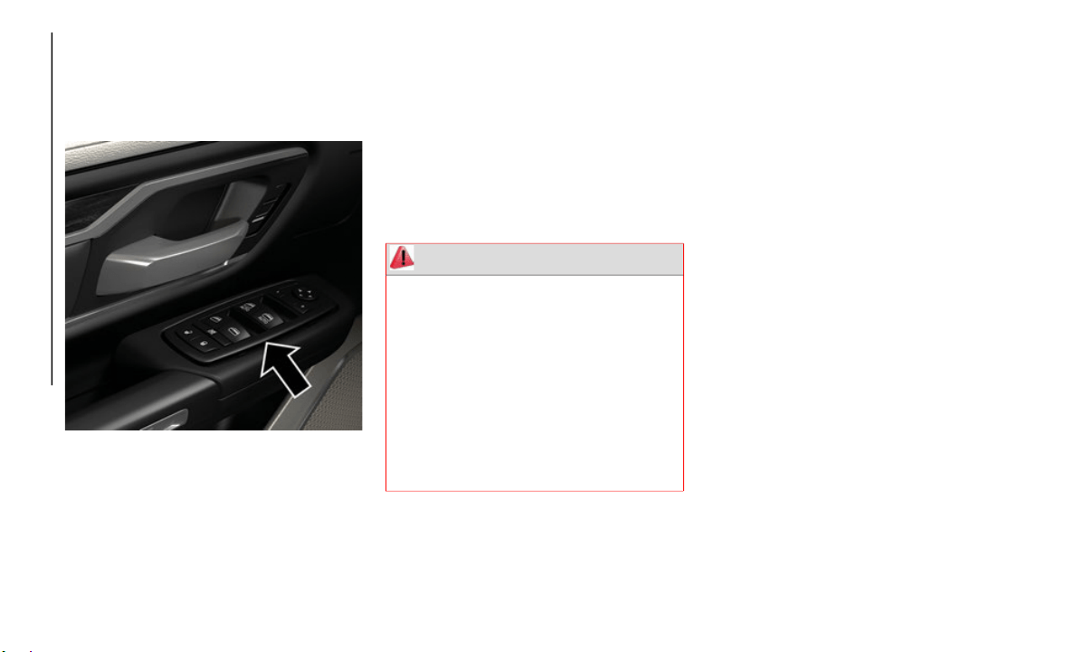
GETTING TO KNOW YOUR VEHICLE
44
WINDOWS
Power Windows
Power Window Controls
Power Window Switches
The power window controls located on the
driver's
door trim panel have up-down
switches that give you fingertip control of all
power windows. There is a single opening
and closing switch on the front passenger
door for passenger window control and on the
rear doors for rear window control. The
windows will operate when the ignition
switch is turned to the ON/RUN or ACC posi
-
tion, and for up to 10 minutes after the igni-
tion is turned OFF or until a front door is
o
pened.
NOT
E:
The Key Off Power Delay feature will allow
t
he power
windows to operate for up to
10
minutes after the ignition is turned OFF.
This feat
ure is cancelled when either front
door is opened.
Auto-Down
Both the driver and front passenger window
switch have an Auto-Down feature. Push the
window switch past the first detent, release,
and the window will go down automatically.
To cancel the Auto-Down movement, operate
the switch in either the up or down direction
and release the switch.
To stop the window from going all the way
down duri
ng the Auto-Down operation, pull
up on the switch briefly.
To open the window part way, push to the
switch to
the first detent and release it when
you want the window to stop.
Auto-Up Feature With Anti-Pinch Protection
— If Equipped
Pull the window switch fully upward to the
second detent, release, and the window will
go up automatically.
To stop the window from going all the way up
during th
e Auto-Up operation, push down on
the switch briefly.
To close the window part way, lift the window
switch to
the first detent and release when
you want the window to stop.
NOTE:
If the window runs into any obstacle during
the Auto-
Closure, it will reverse direction and
then go back down. Remove the obstacle and
use the window switch again to close the
window. Any impact due to rough road condi
-
tions may trigger the auto reverse function
WARNING!
Never leave children unattended in a
vehicle. Do not leave the key fob in or near
the vehicle or in a location accessible to
children, and do not leave the ignition of a
vehicle equipped with Keyless Enter-N-Go
in the ACC or ON/RUN mode. Occupants,
particularly unattended children, can
become entrapped by the windows while
operating the power window switches.
Such entrapment may result in serious
injury or death.

45
unexpectedly during auto closure. If this
happens, pull the switch lightly to the first
detent and hold to close the window manu
-
ally.
Window Lockout Switch
The window lockout switch on the driver's
door allows you to disable the window control
on the rear passenger doors. To disable the
window controls on the rear passenger doors,
push the window lock switch into the latched
or down position. To enable the window
controls, push the window lock switch again
and return the switch to the released or up
position.
Power Sliding Rear Window — If Equipped
The switch for the power sliding rear window
is located on the overhead console.
Push the switch rearward to open the glass.
Pull the
switch forward to close the glass.
Manual Sliding Rear Window — If Equipped
A locking device in the center of the window
helps to prevent entry from the rear of the
vehicle. Squeeze the lock to release the
window.
Wind Buffeting
Wind buffeting can be described as the
perception of pressure on the ears or a heli-
copter-type sound in the ears. Your vehicle
m
ay exhib
it wind buffeting with the windows
down, or the sunroof (if equipped) in certain
open or partially open positions. This is a
normal occurrence and can be minimized. If
the buffeting occurs with the rear windows
open, open the front and rear windows
together to minimize the buffeting. If the
buffeting occurs with the sunroof open,
adjust the sunroof opening to minimize the
buffeting or open any window.
POWER SUNROOF — IF
EQUIPPED
Single Pane Power Sunroof — If Equipped
The power sunroof switches are located on
the overhead console between the courtesy/
reading lights.
Power Sunroof Switches
WARNING!
There is no anti-pinch protection when the
window is almost closed. Be sure to clear
all objects from the window before closing.
1 — Opening/Closing Sunroof
2 — Venting Sunroof

GETTING TO KNOW YOUR VEHICLE
46
Opening Sunroof
Express Open
Push the switch rearward and release it
within on
e-half second, the sunroof and
sunshade will open automatically and stop at
full open position. During Express Open
operation, any other actuation of the sunroof
switches will stop the sunroof in a partially
open position.
Manual Open
Push and hold the switch rearward, the
sunroof a
nd sunshade will open and auto-
matically stop at full open position.
R
eleasing
the switch while the sunroof is in
motion will stop sunroof in a partially open
position.
Vent Open
Push and release the Vent switch within one
half seco
nd and the sunroof will open to the
vent position. During Express Vent operation,
any other actuation of the sunroof switches
will stop the sunroof operation.
Closing Sunroof
Express Close
Push the switch forward and release it within
one-half
second and the sunroof will close
automatically from any position. During
Express Close operation, any other actuation
of the sunroof switches will stop the sunroof
in a partially open position.
Manual Close
Push and hold the switch forward and the
sunroof w
ill close from any position and stop
at full closed position. Releasing the switch
while the sunroof is in motion will stop
sunroof in a partially open position.
Sunshade Operation
The sunshade can be opened manually.
However, the sunshade will open automati-
cally as the sunroof opens.
NOTE:
The sunshade cannot be closed if the
s
unroof i
s open.
Pinch Protect Feature
This feature will detect an obstruction in the
closing of the sunroof during the Express
Close operation. If an obstruction in the path
of the sunroof is detected, the sunroof will
automatically retract. Remove the obstruc
-
tion if this occurs.
WARNING!
Never leave children unattended in a
vehicle, or with access to an unlocked
vehicle. Never leave the key fob in or
near the vehicle, or in a location acces
-
sible to children. Do not leave the igni-
tion of a vehicle equipped with Keyless
Enter-N-G
o in the ACC or ON/RUN
mode. Occupants, particularly unat
-
tended children, can become entrapped
by the po
wer sunroof while operating the
power sunroof switch. Such entrapment
may result in serious injury or death.
In a collision, there is a greater risk of
being thrown from a vehicle with an open
sunroof. You could also be seriously
injured or killed. Always fasten your seat
belt properly and make sure all passen
-
gers are also properly secured.
Do not allow small children to operate
the sunroof. Never allow your fingers,
other body parts, or any object, to project
through the sunroof opening. Injury may
result.
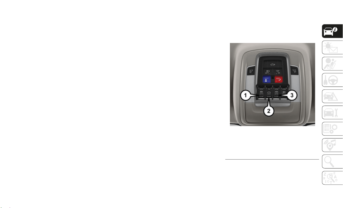
47
NOTE:
If three consecutive sunroof close attempts
result in
Pinch Protect reversals, Pinch
Protect will disable and the sunroof must be
closed in Manual Mode.
Sunroof Maintenance
Use only a non-abrasive cleaner and a soft
cloth to clean the glass panel.
Ignition Off Operation
The power sunroof switch will remain active
for up to approximately 10 minutes after the
ignition
switch is turned to the OFF/LOCK
position. Opening either front door will
cancel this feature.
NOTE:
Ignition Off time is programmable through
the Uconn
ect System. Refer to “Uconnect
Settings” in “Multimedia” in the Owner’s
Manual for further information.
Calibration Procedure
If the sunroof “Express Operation” feature is
no longer functioning, or the sunroof is
auto-reversing while attempting to “Express
Close” but no obstruction is in the roof
opening, the sunroof can be re-calibrated per
the following steps:
1. Set the ignition to ACC or ON/RUN.
2. Close
sunroof glass.
3. With s
unroof in closed position, push and
hold the
close switch.
4. After 10 seconds of holding switch, the
sunroof
glass will cycle into the vent posi-
tion and stop.
5. R
elease the close switch, then within 5
seconds
push and hold the close switch
again. The sunroof will cycle open and
back to closed as the switch is held.
6. Once the sunroof has stopped in the full
closed p
osition, release the close switch.
The sunroof is now reset and ready to
use.
Dual Pane Power Sunroof — If Equipped
The power sunroof switches are located on
the overhead console between the courtesy/
reading lights.
Power Sunroof Switches
1 — Opening/Closing Sunroof
2 — Venting Sunroof
3 — Opening/Closing Sunshade

GETTING TO KNOW YOUR VEHICLE
48
Opening Sunroof
The sunroof has two programmed open posi-
tions, comfort stop position and full open
position.
The comfort stop position has been
optimized to minimize wind buffeting when
driving with side windows closed and sunroof
open. If the sunshade is in the closed posi
-
tion when initiating a sunroof open
command t
he sunshade will automatically
open to the half open position prior to the
sunroof opening.
Express Open
Push the switch rearward and release it
within on
e-half second, the sunroof will open
to the comfort stop position and automati
-
cally stop. Push the switch rearward and
release i
t again, the sunroof will open to the
full open position and automatically stop.
During Express Open operation, any actua
-
tion of the sunroof switches will stop the
sunroof i
n a partially open position.
Manual Close
Push and hold the switch rearward, the
s
unroof w
ill open to the comfort stop position
and automatically stop. Push the switch rear
-
ward and hold it again, the sunroof will open
to the fu
ll open position and automatically
stop. Releasing the switch while the sunroof
is in motion will stop the sunroof in a
partially open position.
Vent Open
Push and release the Vent open switch
within on
e half second and the sunroof will
open to the vent position. During Express
Vent operation, any other actuation of the
sunroof switches will stop the sunroof opera
-
tion.
Closing Sunroof
Express Close
Push the switch forward and release it within
one-half
second and the sunroof will close
automatically from any position. During
Express Close operation, any other actuation
of the sunroof switches will stop the sunroof
in a partially open position.
Manual Close
Push and hold the switch forward and the
sunroof w
ill close from any position and stop
at full closed position. Releasing the switch
while the sunroof is in motion will stop the
sunroof in a partially open position.
Opening Power Sunshade
The sunshade has two programmed open
positions, half open and full open positions.
When opening the sunshade from the closed
position the sunshade will always stop at the
WARNING!
Never leave children unattended in a
vehicle, or with access to an unlocked
vehicle. Never leave the key fob in or
near the vehicle, or in a location acces
-
sible to children. Do not leave the igni-
tion of a vehicle equipped with Keyless
Enter-N-G
o in the ACC or ON/RUN
mode. Occupants, particularly unat
-
tended children, can become entrapped
by the po
wer sunroof while operating the
power sunroof switch. Such entrapment
may result in serious injury or death.
In a collision, there is a greater risk of
being thrown from a vehicle with an open
sunroof. You could also be seriously
injured or killed. Always fasten your seat
belt properly and make sure all passen
-
gers are also properly secured.
Do not allow small children to operate
the sunroof. Never allow your fingers,
other body parts, or any object, to project
through the sunroof opening. Injury may
result.

49
half open position regardless of express or
manual open operation. The switch must be
actuated again to continue on to full open
position
Express Open
Push the sunshade switch rearward and
release i
t within one-half second, the
sunshade will open to the half open position
and stop automatically. Push and release the
switch again from the half open position and
the sunshade will open to the full open posi
-
tion and stop automatically. During Express
O
pen oper
ation, any actuation of the sunroof
switches will stop the sunshade in a partially
open position.
Manual Close
Push and hold the sunshade switch rear-
ward, the sunshade will open to the half open
position
and stop automatically. Push and
hold the sunshade switch rearward again and
the shade will open automatically to the
full-open position. Releasing the switch
while the sunshade is in motion will stop the
sunshade in a partially open position.
Closing Power Sunshade
If the sunroof is open or vented, the
sunshade cannot be closed beyond the half
open position. Pushing the sunshade close
switch when the sunroof is open/vented and
the sunshade is at half open position will
automatically close the sunroof prior to the
sunshade closing.
Express Close
Push the sunshade switch forward and
release i
t within one-half second and the
sunshade will close automatically. During
Express Close operation, any other actuation
of the sunroof switches will stop the
sunshade in a partially open position.
Manual Close
Push and hold the switch forward and the
sunshade
will close and stop at full closed
position. Releasing the switch while the
sunshade is in motion will stop the sunshade
in a partially open position.
Pinch Protect Feature
This feature will detect an obstruction in the
closing of the sunroof during the Express
Close operation. If an obstruction in the path
of the sunroof is detected, the sunroof will
automatically retract. Remove the obstruc
-
tion if this occurs.
NOTE:
If three consecutive sunroof close attempts
result in
Pinch Protect reversals, Pinch
Protect will disable and the sunroof must be
closed in Manual Mode.
Sunroof Maintenance
Use only a non-abrasive cleaner and a soft
cloth to clean the glass panel.
Ignition Off Operation
The power sunroof switch will remain active
for up to approximately 10 minutes after the
ignition
switch is turned to the OFF/LOCK
position. Opening either front door will
cancel this feature.
NOTE:
Ignition Off time is programmable through
the Uconnect System. Refer to “Uconnect
Settings” in “Multimedia” in the Owner’s
Manual for further information.
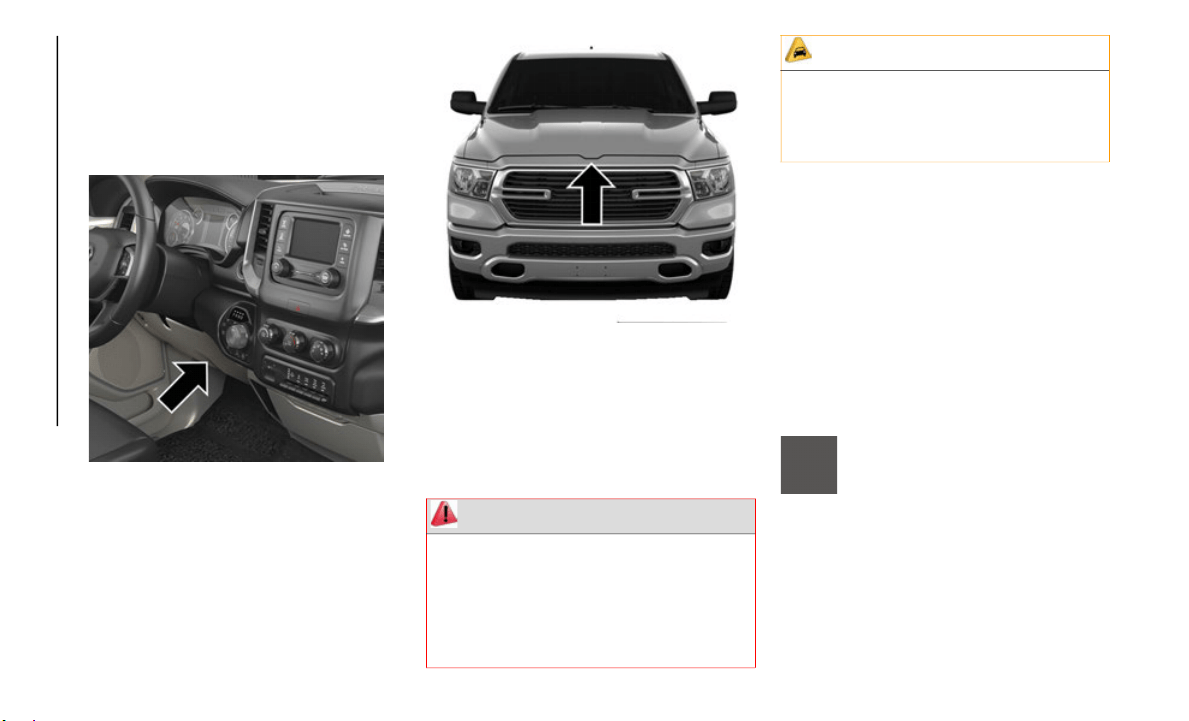
GETTING TO KNOW YOUR VEHICLE
50
HOOD
To Open The Hood
To open the hood, two latches must be
released.
Hood Release Lever Location
1. Pull the hood release lever located below
the steer
ing wheel at the base of the
instrument panel.
2. Reach into the opening beneath the
center of
the hood and push the safety
latch lever to the left to release it, before
raising the hood.
Safety Latch Location
To Close The Hood
Lower the hood to approximately 12 inches
(30 cm) from the engine compartment and
drop it. Make sure that the hood is
completely closed.
TAILGATE
Opening
The power tailgate may be opened by
pushing the tailgate release pad located on
the tailgate door.
The tailgate damper strut will lower the tail-
gate to the open position (if equipped).
Electronic Tailgate Release — If Equipped
The key fob may be equipped with
an electronic release feature for the
tailgate,
allowing hands-free tail-
gate opening. To activate, push and
r
elease th
e Tailgate Release button on the
key fob twice within five seconds. The tail
-
gate door will unlatch, and slowly lower into
the open p
osition.
WARNING!
Be sure the hood is fully latched before
driving your vehicle. If the hood is not fully
latched, it could open when the vehicle is
in motion and block your vision. Failure to
follow this warning could result in serious
injury or death.
CAUTION!
To prevent possible damage, do not slam
the hood to close it. Use a firm downward
push at the front center of the hood to
ensure that both latches engage.
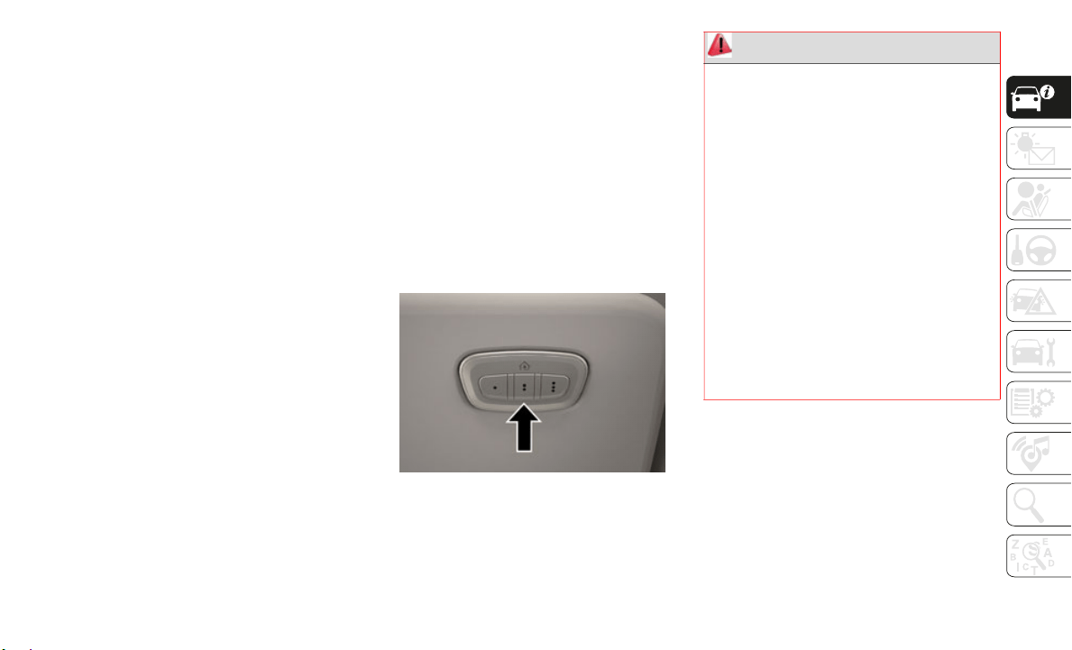
51
If equipped, a button on the center overhead
console inside the vehicle can be used to
release the tailgate. An indicator light may
also signal when the tailgate is open (if
equipped).
NOTE:
The Tri-Fold Tonneau Cover (if equipped)
m
ay preve
nt Electronic Tailgate Release if
installed. The Tonneau Cover must be
removed or folded up before releasing the
tailgate. Refer to “Tri-Fold Tonneau Cover —
If Equipped” in “Getting To Know Your
Vehicle” in the Owner’s Manual for further
information.
Closing
To close the tailgate, push it upward until
both sides are latched.
NOTE:
Pull back on the tailgate firmly after closing
t
o ensure
it is securely latched.
GARAGE DOOR OPENER —
IF EQUIPPED
HomeLink replaces up to three hand-held
transmitters that operate devices such as
garage door openers, motorized gates,
lighting or home security systems. The
HomeLink unit is powered by your vehicles
12 Volt battery.
The HomeLink buttons that are located on
the sun v
isor designate the three different
HomeLink channels.
HomeLink Buttons
NOTE:
HomeLink is disabled when the Vehicle
S
ecurity
Alarm is active.
NOTE:
Only use this transceiver with a garage door
opener that has a “stop and reverse” feature
as required by federal safety standards. This
includes most garage door opener models
manufactured after 1982. Do not use a
garage door opener without these safety
features. Call toll-free 1-800-355-3515 or,
on the Internet at
HomeLink.com for safety
information or assistance.
WARNING!
Your motorized door or gate will open and
close while you are programming the
universal transceiver. Do not program the
transceiver if people, pets or other objects
are in the path of the door or gate. Only use
this transceiver with a garage door opener
that has a “stop and reverse” feature as
required by Federal safety standards. This
includes most garage door opener models
manufactured after 1982. Do not use a
garage door opener without these safety
features.
Vehicle exhaust contains carbon
monoxide, a dangerous gas. Do not run
your vehicle in the garage while program
-
ming the transceiver. Exhaust gas can
cause ser
ious injury or death.

GETTING TO KNOW YOUR VEHICLE
52
Before You Begin Programming
HomeLink
Be sure that your vehicle is parked outside of
the garage before you begin programming.
For more efficient programming and accu-
rate transmission of the radio-frequency
s
ignal it
is recommended that a new battery
be placed in the hand-held transmitter of the
device that is being programmed to the
HomeLink system.
To erase the channels, place the ignition in
the ON/RU
N position, and push and hold the
two outside HomeLink buttons (I and III) for
up to 20 seconds or until the orange indi
-
cator flashes.
NOTE:
Erasing all channels should only be
performed when programming HomeLink
for the first time. Do not erase channels
when programming additional buttons.
If you have any problems, or require assis-
tance, please call toll-free
1-800-355
-3515 or, on the Internet at
HomeLink.com for information or assis-
tance.
Programming A Rolling Code
For programming garage door openers that
were manufactured after 1995. These
garage door openers can be identified by the
“LEARN” or “TRAIN” button located where
the hanging antenna is attached to the
garage door opener.
NOTE:
It is NOT the button that is normally used to
open and
close the door. The name and color
of the button may vary by manufacturer.
1. Place the ignition in the ON/RUN posi-
tion.
2. Pl
ace the hand-held transmitter 1 to
3 inches
(3 to 8 cm) away from the
HomeLink
button you wish to program
while keeping the HomeLink indicator
light in view.
3. Push and hold the HomeLink button you
want to
program while you push and hold
the hand-held transmitter button.
4. Continue to hold both buttons and
observe
the indicator light. The Home-
Link indicator will flash slowly and then
r
apidly a
fter HomeLink has received the
frequency signal from the hand-held
transmitter. Release both buttons after
the indicator light changes from slow to
rapid.
5. At the garage door opener motor (in the
garage),
locate the “LEARN” or
“TRAINING” button. This can usually be
found where the hanging antenna wire is
attached to the garage door opener/
device motor. Firmly push and release
the “LEARN” or “TRAINING” button. On
some garage door openers/devices there
may be a light that blinks when the
garage door opener/device is in the
LEARN/TRAIN mode.
NOTE:
You have 30 seconds in which to initiate the
n
ext step
after the LEARN button has been
pushed.
6. Return to the vehicle and push the
programm
ed HomeLink button twice
(holding the button for two seconds each
time). If the garage door opener/device
activates, programming is complete.
NOTE:
If the garage door opener/device does not
activate,
push the button a third time (for
two seconds) to complete the training.

53
To program the remaining two HomeLink
buttons, repeat each step for each re-
maining button. DO NOT erase the chan-
nels.
Reprogramming A Single HomeLink Button
(
Rolling
Code)
To reprogram a channel that has been previ-
ously trained, follow these steps:
1. C
ycle the ignition to the ON/RUN posi-
tion.
2. Pu
sh and hold the desired HomeLink
button u
ntil the indicator light begins to
flash after 20 seconds. Do not release
the button.
3. Without releasing the button proceed
with “Pr
ogramming A Rolling Code” step
2 and follow all remaining steps."
Programming A Non-Rolling Code
For programming Garage Door Openers
manufactured before 1995.
1. Cycle the ignition to the ON/RUN posi-
tion.
2. Pl
ace the hand-held transmitter 1 to
3 inches
(3 to 8 cm) away from the
HomeLink
button you wish to program
while keeping the HomeLink indicator
light in view.
3. Press and hold the HomeLink button you
want to
program while you press and hold
the hand-held transmitter button.
4. Continue to hold both buttons and
observe
the indicator light. The Home-
Link indicator will flash slowly and then
r
apidly a
fter HomeLink has received the
frequency signal from the hand-held
transmitter. Release both buttons after
the indicator light changes from slow to
rapid.
5. Press and hold the programmed Home-
Link but
ton and observe the indicator
light.
If the indicator light stays on constantly,
programming is complete and the garage
door/device should activate when the
HomeLink button is pressed.
To program the two remaining HomeLink
buttons, repeat each step for each
remaining button. DO NOT erase the
channels.
Reprogramming A Single HomeLink Button
(Non-Roll
ing Code)
To reprogram a channel that has been previ-
ously trained, follow these steps:
1. C
ycle the ignition to the ON/RUN posi-
tion.
2. Pr
ess and hold the desired HomeLink
button u
ntil the indicator light begins to
flash after 20 seconds. Do not release
the button.
3. Without releasing the button, proceed
with “Pr
ogramming A Non-Rolling Code”
step 2 and follow all remaining steps.
Canadian/Gate Operator Programming
For programming transmitters in Canada/
United States that require the transmitter
signals to “time-out” after several seconds of
transmission.
Canadian radio frequency laws require trans-
mitter signals to time-out (or quit) after
several seconds of transmission – which may
not be long enough for HomeLink to pick up
the signal during programming. Similar to
this Canadian law, some U.S. gate operators
are designed to time-out in the same
manner.

GETTING TO KNOW YOUR VEHICLE
54
It may be helpful to unplug the device during
the cycling process to prevent possible over-
heating of the garage door or gate motor.
1. C
ycle the ignition to the ON/RUN posi-
tion.
2. Pl
ace the hand-held transmitter 1 to
3 inches
(3 to 8 cm) away from the
HomeLink
button you wish to program
while keeping the HomeLink indicator
light in view.
3. Continue to press and hold the HomeLink
button,
while you press and release
(“cycle”) your hand-held transmitter
every two seconds until HomeLink has
successfully accepted the frequency
signal. The indicator light will flash
slowly and then rapidly when fully
trained.
4. Watch for the HomeLink indicator to
change f
lash rates. When it changes, it is
programmed. It may take up to 30
seconds or longer in rare cases. The
garage door may open and close while
you are programming.
5. Press and hold the programmed Home-
Link but
ton and observe the indicator
light.
NOTE
:
If the indicator light stays on constantly,
programming is complete and the garage
door/device should activate when the
HomeLink button is pressed.
To program the two remaining HomeLink
buttons, repeat each step for each
remaining button. DO NOT erase the
channels.
If you unplugged the garage door opener/
device fo
r programming, plug it back in at
this time.
Reprogramming A Single HomeLink Button
(Canadian
/Gate Operator)
To reprogram a channel that has been previ-
ously trained, follow these steps:
1. C
ycle the ignition to the ON/RUN position.
2. Press
and hold the desired HomeLink
button u
ntil the indicator light begins to
flash after 20 seconds. Do not release the
button.
3. Without releasing the button, proceed with
“Canadia
n/Gate Operator Programming”
step 2 and follow all remaining steps.
Using HomeLink
To operate, push and release the
programmed HomeLink button. Activation
will now occur for the programmed device
(i.e. garage door opener, gate operator, secu
-
rity system, entry door lock, home/office
lighting,
etc.) The hand-held transmitter of
the device may also be used at any time.
Security
It is advised to erase all channels before you
sell or turn in your vehicle.
To do this, push and hold the two outside
buttons f
or 20 seconds until the orange indi-
cator flashes. Note that all channels will be
e
rased. I
ndividual channels cannot be
erased.
The HomeLink Universal Transceiver is
disabled
when the Vehicle Security Alarm is
active.
Troubleshooting Tips
If you are having trouble programming
HomeLink, here are some of the most
common solutions:
Replace the battery in the Garage Door
Opener hand-held transmitter.
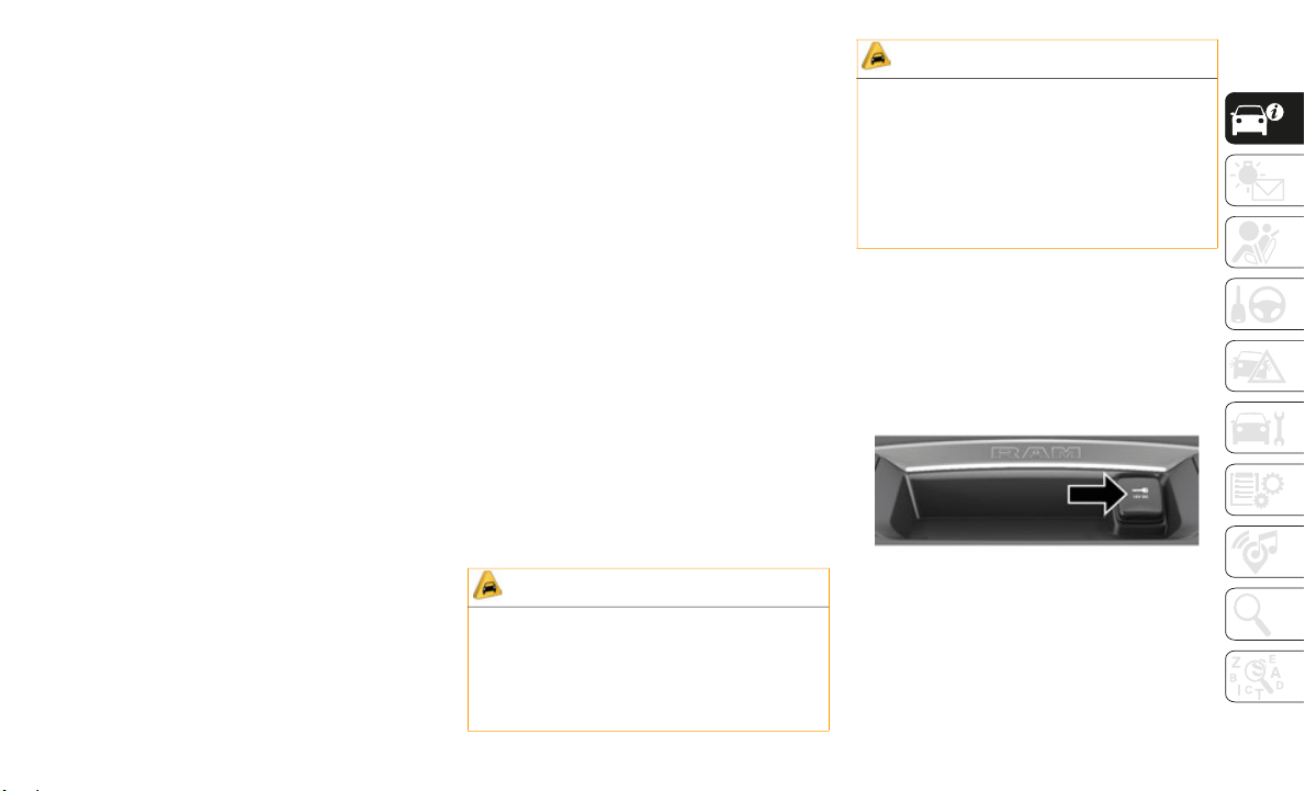
55
(Continued)
Push the LEARN button on the Garage
Door Opener to complete the training for a
Rolling Code.
Did you unplug the device for program-
ming and remember to plug it back in?
If you have any problems, or require assis-
tance, please call toll-free 1
-800-355
-3515
or, on the Internet at HomeLink.com for
information or assistance.
General Information
The following regulatory statement applies to
all Radio Frequency (RF) devices equipped
in this vehicle:
This device complies with Part 15 of the FCC
Rules and
with Innovation, Science and
Economic Development Canada
license-exempt RSS standard(s). Operation
is subject to the following two conditions:
1. This device may not cause harmful inter-
ference,
and
2. This device must accept any interference
received
, including interference that may
cause undesired operation.
NOTE:
Changes or modifications not expressly
approved
by the party responsible for compli-
ance could void the user’s authority to
o
perate t
he equipment.
INTERNAL EQUIPMENT
Electrical Power Outlets
The auxiliary 12 Volt (13 Amp) power outlet
can provide power for in-cab accessories
designed for use with the standard “cigar
lighter” plug. The 12 Volt power outlets and
5 Volt (2.5 Amp) USB Port (Charge Only)
have a cap attached to the outlet indicating
“12V DC,” together with either a key symbol,
battery symbol, or USB symbol.
A key symbol indicates that the key must be
in the ON
/RUN or ACC positions for the
outlet to provide power. The battery symbol
indicates that the outlet is connected to the
battery, and can provide power at all times.
An auxiliary power outlet can be found in the
tray on t
op of the center stack. This power
outlet only works when the vehicle is in the
ON/RUN or ACC position.
Power Outlet — Top Of Center Stack
CAUTION!
Do not exceed the maximum power of
160 Watts (13 Amps) at 12 Volts. If the
160 Watts (13 Amps) power rating is
exceeded, the fuse protecting the system
will need to be replaced.
Power outlets are designed for accessory
plugs only. Do not insert any other object
in the power outlets as this will damage
the outlet and blow the fuse. Improper
use of the power outlet can cause
damage not covered by your New Vehicle
Limited Warranty.
CAUTION! (Continued)
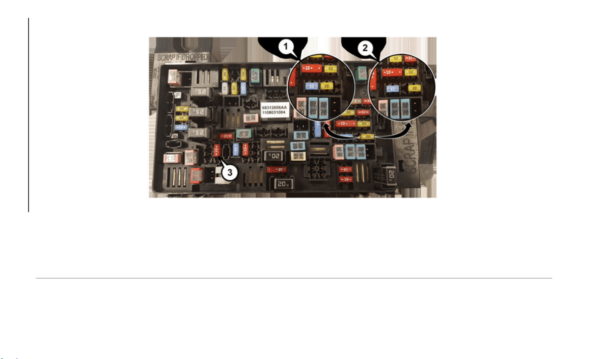
GETTING TO KNOW YOUR VEHICLE
56
Power Outlet Fuse Locations
1 — F54 Fuse 20 A Yellow Power Outlet Battery Fed Position
2 — F54 Fuse 20 A Yellow Power Outlet Ignition Fed Position
3 — F48 Fuse 10 A Red Port Power or Rear USB (Charge Only)

57
(Continued)
When the vehicle is turned off, be sure to
unplug any equipment as to not drain the
battery of the vehicle. All accessories
connected to the outlet(s) should be
removed or turned off when the vehicle is not
in use to protect the battery against
discharge.
Power Inverter — If Equipped
If equipped, a 115 Volt (400 Watts
Maximum) inverter may be located inside the
center console towards the right hand side,
just under the Wireless Charging Pad (if
equipped). This inverter can power cellular
phones, electronics and other low power
devices requiring power up to 400 Watts.
Certain high-end video game consoles
exceed this power limit, as will most power
tools.
Center Console Power Inverter Outlet
There is also a second 115 Volt (400 Watts
M
aximum)
power inverter located on the rear of
the center console. This inverter can power
cellular phones, electronics and other low power
devices requiring power up to 400 Watts. Certain
high-end video game consoles exceed this power
limit, as will most power tools.
All power inverters are designed with built-in
overload
protection. If the power rating of
400 Watts is exceeded, the power inverter
shuts down. Once the electrical device has
been removed from the outlet the inverter
should reset.
WARNING!
To avoid serious injury or death:
Only devices designed for use in this
type of outlet should be inserted into any
12 Volt outlet.
Do not touch with wet hands.
Close the lid when not in use and while
driving the vehicle.
If this outlet is mishandled, it may cause
an electric shock and failure.
CAUTION!
Many accessories that can be plugged in
draw power from the vehicle's battery, even
when not in use (i.e., cellular phones,
etc.). Eventually, if plugged in long
enough, the vehicle's battery will discharge
sufficiently to degrade battery life and/or
prevent the engine from starting.
Accessories that draw higher power (i.e.,
coolers, vacuum cleaners, lights, etc.),
will discharge the battery even more
quickly. Only use these intermittently
and with greater caution.
After the use of high power draw acces-
sories, or long periods of the vehicle not
being sta
rted (with accessories still
plugged in), the vehicle must be driven a
sufficient length of time to allow the
generator to recharge the vehicle's
battery.
CAUTION! (Continued)
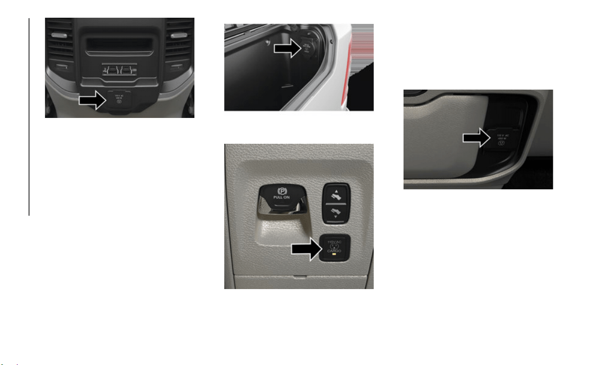
GETTING TO KNOW YOUR VEHICLE
58
Rear Center Console Power Inverter Outlet
NOTE:
400 Watts is the maximum for the inverter,
n
ot each
outlet. If three outlets are in use,
400 Watts is shared amongst the devices
plugged in.
If equipped, a 115 Volt (400 Watts Maximum)
inverter
may be located inside the ram box of
your vehicle. The inverter can be turned on by
the Instrument Panel Power Inverter switch
located to the left of the steering wheel. This
inverter can power cellular phones, electronics
and other low power devices requiring power up
to 400 Watts. Certain high-end video game
consoles exceed this power limit, as will most
power tools.
Ram Box Power Inverter
Instrument Panel Power Inverter Switch
If equipped, there may be a 115 Volt
(
400 Watts
Maximum) inverter located to
the right of the center stack, just below
the climate controls. This inverter can
power cellular phones, electronics and
other low power devices requiring power
up to 400 Watts. Certain high-end video
game consoles exceed this power limit,
as will most power tools.
Center Stack Power Inverter
To turn on the power outlet, simply plug in
t
he devic
e. The outlet turns off when the
device is unplugged.
NOTE:
The Power Inverter only turns on if the
ignition is in the ACC or ON/RUN position.
Due to built-in overload protection, the
power inverter shuts down if the power
rating is exceeded.
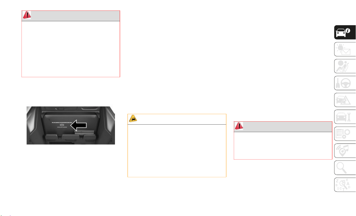
59
(Continued)
Wireless Charging Pad — If Equipped
Wireless Charging Pad
Your vehicle may be equipped with a 15W
3A Qi wir
eless charging pad located inside of
the center console just below the CD player
(if equipped). This charging pad is designed
to wirelessly charge your Qi enabled mobile
phone. Qi is a standard that uses magnetic
induction to transfer power to your mobile
device.
Your mobile phone must be designed for Qi
wireless
charging. If the phone is not
equipped with Qi wireless charging function
-
ality, an aftermarket sleeve or a specialized
back plat
e can be purchased from your
mobile phone provider or an local electronics
retailer. Please see your phone’s owner’s
manual for further information.
The wireless charging pad is equipped with
an anti-s
lip mat, an adjustable cradle to hold
your mobile phone in place and an LED indi
-
cator light.
PICKUP BOX
The pickup box has many features designed
for utility and convenience.
NOTE:
If you are installing a Toolbox, Ladder Rack
o
r Headac
he Rack at the front of the Pickup
Box, you must use Mopar Box Reinforcement
Brackets that are available from an autho
-
rized dealer.
You can carry wide building materials
(sheets o
f plywood, etc.) by building a raised
load floor. Place lumber across the box in the
indentations provided above the wheel hous
-
ings and in the bulkhead dividers to form the
floor.
WARNING!
To avoid serious injury or death:
Do not insert any objects into the recep-
tacles.
Do not touch with wet hands.
Close the lid when not in use.
If this outlet is mishandled, it may cause
an electric shock and failure.
CAUTION!
The key fob should not be placed on the
charging pad or within 15 cm (150 mm)
of it. Do
ing so can cause excessive heat
buildup and damage to the fob. Placing
the fob in close proximity of the charging
pad blocks the fob from being detected by
the vehicle and prevents the vehicle from
starting.
WARNING!
The pickup box is intended for load
carrying purposes only, not for passen-
gers, who should sit in seats and use seat
b
elts.

GETTING TO KNOW YOUR VEHICLE
60
(Continued)
There are stampings in the sheet metal on
the inner side bulkheads of the box in front
of and behind both wheel housings. Place
wooden boards across the box from side to
side to create separate load compartments in
the pickup box.
There are four tie-down cleats bolted to the
lower sid
es of the pickup box that can
sustain loads up to 1000 lbs (450 kg) total.
RAMBOX — IF EQUIPPED
The RamBox system is an integrated pickup
box storage and cargo management system
consisting of three features:
Integrated box side storage bins
Cargo divider
Bed rail tie-down system
NOTE:
Bed rail tie-down system is also available for
v
ehicles
not equipped with a RamBox.
RamBox Integrated Box Side Storage Bins
Cargo storage bins are located on both sides
of the pickup box. The cargo storage bins
provide watertight, lockable, illuminated
storage for up to 150 lbs (68 kg) of evenly
distributed cargo.
To open a storage bin with the RamBox
unlocked,
push and release the button
located on the lid. The RamBox lid will open
upward to allow hand access. Lift the lid to
fully open.
NOTE:
RamBox will not open when the pushbutton
i
s pushed
if the RamBox is locked.
The interior of the RamBox will automatically
illuminat
e when the lid is opened. The
timing can be adjusted through your touch
-
screen.
Refer to “Uconnect Settings” in “Multi-
media” in your Owner’s Manual for further
informati
on.
Care should always be exercised when
operating a vehicle with unrestrained
cargo. Vehicle speeds may need to be
reduced. Severe turns or rough roads may
cause shifting or bouncing of the cargo
that may result in vehicle damage. If wide
building materials are to be frequently
carried, the installation of a support is
recommended. This will restrain the cargo
and transfer the load to the pickup box
floor.
If you wish to carry more than 600 lbs
(272 kg) of material suspended above the
wheelhouse, supports must be installed to
transfer the weight of the load to the
pickup box floor or vehicle damage may
result. The use of proper supports will
permit loading up to the rated payload.
Unrestrained cargo may be thrown forward
in an accident causing serious or fatal
injury.
WARNING! (Continued)
CAUTION!
Failure to follow the following items could
cause damage to the vehicle:
Assure that all cargo inside the storage
bins is properly secured.
Do not exceed cargo weight rating of 150 lb
(68 kg) per bin.
CAUTION!
Leaving the lid open for extended periods
of time could cause the vehicle battery to
discharge. If the lid is required to stay
open for extended periods of time, it is
recommended that the bin lights be turned
off manually using the on/off switch.
CAUTION! (Continued)
61
(Continued)
Cargo bins feature two removable drain plugs
(to allow water to drain from bins). To remove
plug, pull up on the edge. To install push
plug downward into drain hole.
If equipped, a power inverter can be found
inside th
e RamBox.
Refer to “Electrical Power Outlets” in
“Getting
To Know Your Vehicle” in your
Owner’s Manual for further information.
NOTE:
Provisions are provided in the bins for cargo
dividers.
These accessories (in addition to
other RamBox accessories) are available
from Mopar.
Locking And Unlocking RamBox
Push and release the lock or unlock button on
the key fob to lock and unlock all doors, the
tailgate and the RamBox (if equipped). The
RamBox storage bins can also be locked using
the emergency key. To lock and unlock the
storage bin, insert the emergency key into the
keyhole and turn clockwise to lock or counter
-
clockwise to unlock. Always return the key to
the uprig
ht (vertical) position before removing
it from the keyhole.
Refer to “Keys” in “Getting To Know Your
Vehicle”
in the Owner’s Manual for further
details.
RamBox Safety Warning
Carefully follow these warnings to help prevent
personal injury or damage to your vehicle:
RamBox Storage Bin Cover Emergency
Release Lever — If Equipped
As a security measure, a Storage Bin Cover
Emergency Release is built into the storage
bin cover latching mechanism.
NOTE:
In the event of an individual being locked
inside th
e storage bin, the storage bin cover
can be opened from inside of the bin by
pulling on the glow-in-the-dark lever
attached to the storage bin cover latching
mechanism.
CAUTION!
Ensure cargo bin lids are closed and
latched before moving or driving vehicle.
Loads applied to the top of the bin lid
should be minimized to prevent damage to
the lid and latching/hinging mechanisms.
Damage to the RamBox bin may occur due
to heavy/sharp objects placed in bin that
shift due to vehicle motion. In order to
minimize potential for damage, secure all
cargo to prevent movement and protect
inside surfaces of bin from heavy/sharp
objects with appropriate padding.
WARNING!
Always close the storage bin covers when
your vehicle is unattended.
Do not allow children to have access to the
storage bins. Once in the storage bin,
young children may not be able to escape.
If trapped in the storage bin, children can
die from suffocation or heat stroke.
In an accident, serious injury could result
if the storage bin covers are not properly
latched.
Do not drive the vehicle with the storage
bin covers open.
Keep the storage bin covers closed and
latched while the vehicle is in motion.
Do not use a storage bin latch as a tie
down.
WARNING! (Continued)

GETTING TO KNOW YOUR VEHICLE
62
Bed Divider — If Equipped
The bed divider has two functional positions:
Storage Position
Divider Position
Storage Position
The storage position for the bed divider is at
the front of the truck bed which maximizes
the bed cargo area when not in use.
To install the bed divider into the storage
position,
perform the following:
1. Make sure the center handle is unlocked
using th
e vehicle key and rotate the
center handle vertically to release the
divider side gates.
2. With the side gates open, position the
divider
fully forward in the bed against
the front panel.
3. Rotate the side gates closed allowing the
outboard
ends to be positioned in front of
the cargo tie down loops.
4. Rotate the center handle horizontally to
secure t
he side gates in the closed position.
5. Lock the center handle using the vehicle
key to s
ecure the panel into place.
Divider Position
The divider position is intended for
managing your cargo and assisting in
keeping cargo from moving around the bed.
There are 11 divider slots along the bed
inner panels which allow for various posi
-
tions to assist in managing your cargo.
To install the bed divider into a divider posi-
tion, perform the following:
1. M
ake sure the center handle is unlocked
using th
e vehicle key and rotate the
center handle vertically to release the
divider side gates.
2. With the side gates open, position the
divider
so the outboard ends align with
the intended slots in the sides of the bed.
3. Rotate the side gates closed so that the
outboard
ends are secured into the
intended slots of the bed.
4. Rotate the center handle horizontally to
secure t
he side gates in the closed posi-
tion.
5. L
ock the center handle to secure the
panel in
to place.
Bed Rail Tie-Down System
NOTE:
This feature is available for vehicles both
equipped,
or not equipped, with a RamBox.
There are two adjustable cleats on each side of
the bed t
hat can be used to assist in securing
cargo.
Each cleat must be located and tightened down
in one of
the detents, along either rail, in order
to keep cargo properly secure.
To move the cleat to any position on the rail,
turn the
nut counterclockwise, approximately
three turns. Then pull out on the cleat and slide
it to the detent nearest the desired location.
Make sure the cleat is seated in the detent and
tighten the nut.
To remove the cleats from the utility rail,
remove th
e end cap screw located in the center
of the end cap, using a #T30
Torx head driver.
Remove th
e end cap and slide the cleat off the
end of the rail.
CAUTION!
The maximum load per cleat should not
exceed 250 lbs (113 kg) and the angle of
the load on each cleat should not exceed
45 degrees above horizontal, or damage to
the cleat or cleat rail may occur.

63
SLIDE-IN CAMPERS
Camper Applications
Certain truck models are not recommended
for slide-in campers. To determine if your
vehicle is excluded, please refer to the
“Consumer Information Truck-Camper
Loading” document supplied with your
vehicle. The document is also available
online at
www.ramtrucks.com. For safety
reasons, follow all instructions in this
important
document.
NOTE:
When a cap or pickup camper is installed on
a vehicle
, an alternate Center High-Mounted
Stop Light (CHMSL) must be provided.
EASY-OFF TAILGATE
To simplify mounting of a camper unit with
an overhang, the tailgate can be removed.
NOTE:
The electric connector at the bottom of the
t
ailgate
must be disconnected prior to
removing the tailgate.
Disconnecting The Rear Camera And
Remote Keyless Entry
1. Open the tailgate to access the rear
camera or Remote Keyless Entry
connector bracket located on the rear
sill.
2. Remove the connector bracket from the
sill by
pushing inward in the locking tab.
3. Disconnect the chassis wiring harness,
ensuring
the connector bracket does not
fall into the sill.
4. Connect the chassis plug and bracket
(provide
d in the glove compartment) to
the chassis wiring harness and insert the
bracket back into the sill.
5. Connect the tailgate plug (provided in the
glove co
mpartment) to the tailgate wiring
harness to ensure that the terminals do
not corrode.
6. Tape the tailgate harness and bracket
against
the forward-facing surface of the
tailgate. This will prevent damaging the
connector and bracket when storing or
reinstalling the tailgate.
Removing The Tailgate
1. Disconnect the wiring harness for the
rear camera and or power locks (if
equipped).
NOTE:
Refer to “Disconnecting The Rear Camera
And Remot
e Keyless Entry” in this section.
2. Unlatch the tailgate and remove the
support
cables by releasing the lock tang
from the pivot.
NOTE:
Make sure tailgate is supported when
removing
support cables.
3. Position the tailgate on a 45 degree
angle.
4. R
aise the right side of the tailgate until
the righ
t side pivot clears the hanger
bracket.
WARNING!
To avoid inhaling carbon monoxide, which
is deadly, the exhaust system on vehicles
equipped with “Cap or Slide-In Campers”
should extend beyond the overhanging
camper compartment and be free of leaks.

GETTING TO KNOW YOUR VEHICLE
64
5. Slide the entire tailgate to the right to
free the left side pivot.
6. Remove the tailgate from the vehicle.
NOTE:
Do n
ot carry the tailgate loose in the truck
p
ickup bo
x.
Locking Tailgate
The tailgate can be locked using the key fob
lock button.
TRI-FOLD TONNEAU
COVER — IF EQUIPPED
Your vehicle may be equipped with a Tri-Fold
Tonneau Cover which consists of different
features:
Easy Tri-Fold cover
Tonneau fore aft locator
Crosscar inside bed locator
Front and rear clamps
Stowage strap
Locking capability
NOTE:
The Tonneau Cover can be folded up and
secured a
t the front of the box without
removing it completely.
Tri-Fold Tonneau Cover Removal
To remove the Tonneau Cover follow the
following steps:
1. Open the tailgate to access the rear pair
of Tonne
au Cover clamps located on the
underside of the Cover (left and right
side).
2. Slide the locking lever toward the center
of the t
ruck bed to release the clamp and
pull the handle downward into the
Released Position. Do this for both the
left and right side.
3. Holding the yellow bumper, push the fully
released
clamp to the center and pull up.
Push the handle firmly, and listen for a
clicking sound to confirm the clamps are
in the properly Stowed Position.
4. Lift up on the third panel and fold it onto
the seco
nd panel.
5. Lift up on the second and third panel and
fold the
m onto the first panel.
6. Once in the third panel position, repeat
steps “1
” and “2” on the front set of
clamps.
NOTE:
When folding the second and third
panels, the sections MUST be held
together to avoid damage to the cover
material.
Fold the panel gently. It is not recom-
mended to allow the panels to drop
under the
ir own weight.
7. Make sure to clip both stowage straps to
prevent
the Tonneau Cover panels from
unfolding.
8. With two people, remove the cover.
NOTE:
Be s
ure the Tonneau Cover has been folded
c
ompletel
y before removing.
WARNING!
To avoid inhaling carbon monoxide, which
is deadly, the exhaust system on vehicles
equipped with “Cap or Slide-In Campers”
should extend beyond the overhanging
camper compartment and be free of leaks.

65
Tri-Fold Tonneau Cover Installation
To install the Tonneau Cover follow these
steps:
1. Position the folded Tonneau Cover on the
truck be
d and push the cover forward
against the front of the truck bed. The
Tonneau Cover centers itself when
placed on the vehicle.
2. Slide the locking lever toward the center
of the t
ruck bed and release the clamp,
and pull the handle downward into the
Released Position. Do this for both the
left and right side.
3. Holding the lower end of the clamp, push
it to th
e center and pull up. Push the
handle firmly and listen for a clicking
sound to confirm the clamps are set to
the Clamped Position.
NOTE:
Make sure the J Hook (1) locates itself under
the truck
flange.
4. Disengage the stowage straps.
5. Unfold
Tonneau Cover to the second
panel po
sition.
NOTE:
The vehicle cannot be driven when the
Tonneau C
over is in this position.
6. Completely unfold the Tonneau Cover.
NOTE:
When unfolding the center and rear
panels, the sections MUST be held
together to avoid damage to the cover
material.
Unfold the panel gently. It is not recom-
mended to allow the panels to drop
under the
ir own weight.
7. Repeat steps “2” through “3” for the rear
pair of
clamps.
Tri-Fold Tonneau Cover Cleaning
For proper cleaning of the Tonneau Cover,
use Mopar Whitewall & Vinyl Top Cleaner
and Mopar Leather & Vinyl Conditioner/
Protectant.
CAUTION!
It is the driver’s responsibility to ensure
the Tonneau Cover is properly installed on
the vehicle. Failure to follow this
procedure can result in detachment of the
Tonneau Cover from the vehicle and/or
damage to the vehicle/Tonneau Cover.

66
GETTING TO KNOW YOUR INSTRUMENT PANEL
INSTRUMENT CLUSTER
DISPLAY
Your vehicle will be equipped with an instru-
ment cluster display, which offers useful
informati
on to the driver. With the ignition in
the STOP/OFF mode, opening/closing of a
door will activate the display for viewing, and
display the total miles, or kilometers, in the
odometer. Your instrument cluster display is
designed to display important information
about your vehicle’s systems and features.
Using a driver interactive display located on
the instrument panel, your instrument
cluster display can show you how systems
are working and give you warnings when they
are not. The steering wheel mounted controls
allow you to scroll through the main menus
and submenus. You can access the specific
information you want and make selections
and adjustments.
Instrument Cluster Display Controls
The instrument cluster display features a
driver-interactive display that is located in
the instrument cluster.
The instrument cluster display menu items
may consi
st of the following:
Speedometer
Vehicle Info
Driver Assist
Fuel Economy
Trip
Stop/Start
Trailer Tow
Audio
Messages
Screen Setup
Vehicle Settings (Not Equipped with a
Uconnect touchscreen radio)
The system allows the driver to select infor-
mation by pushing the following instrument
c
luster d
isplay control buttons located on the
left side of the steering wheel:
Instrument Cluster Display Control Buttons
Up And Down Arrow Buttons:
Using the up or down a
rrows allows you to
cycle through the Main Menu Items.
Left And Right Arrow Buttons:
Using the l
eft or right
arrow button allows you
to cycle through the submenu items of the
Main menu item.

67
NOTE:
Holding the up/down or left/right arrow
button will loop the user through the
currently selected menu or options
presented on the screen.
Main menu and submenus wrap for
continuous scrolling.
Upon returning to a main menu, the last
submenu screen viewed within that main
menu will be displayed.
OK Button:
For Digital Speedometer:
Pushing the OK button changes units (mph
or km/h).
For Screen Setup:
OK button allows user to enter menu and
submenus.
Within each submenu layer, the up and
down arrows will allow the user to select
the item of interest.
Pushing the OK button makes the selec-
tion and a confirmation screen will appear
(returnin
g the user to the first page of the
submenu).
Pushing the left arrow button will exit each
submenu layer and return to the main
menu.
Oil Life Reset
Your vehicle is equipped with an engine oil
change indicator system. The “Oil Change
Required” message will display in the instru
-
ment cluster display for five seconds after a
single ch
ime has sounded, to indicate the next
scheduled oil change interval. The engine oil
change indicator system is duty cycle based,
which means the engine oil change interval
may fluctuate, dependent upon your personal
driving style.
Unless reset, this message will continue to
display e
ach time you place the ignition in the
ON/RUN position. To turn off the message
temporarily, push and release the OK or arrow
buttons. To reset the oil change indicator
system (after performing the scheduled main
-
tenance), refer to the following procedure:
1. W
ithout pressing the brake pedal, push the
ENGINE S
TART/STOP button and place
the ignition in the ON/RUN position (do not
start the engine).
2. Push and release the down arro
w button to
scroll downward through the main menu to
“Vehicle Info.”
3. Push and release the right arr
ow button to
access the ”Oil Life” screen.
4. Push and hold the OK button
to reset oil
life. If conditions are met, the gauge and
numeric display will update to show 100%.
If conditions are not met a popup message
of "To reset oil life engine must be off with
ignition in run" will be displayed (for five
seconds), and the user will remain at the
Oil Life screen.
5. Push and release the up or down
arrow
button to exit the submenu screen.
NOTE:
If the indicator message illuminates when you
s
tart the
vehicle, the oil change indicator
system did not reset. If necessary, repeat this
procedure.
Display Menu Items
Push and release the up or down arrow button
until the desired selectable menu icon is high-
lighted in the instrument cluster display.
Refer to “Instrument Cluster Display” in
“Getting To Know Your Instrument Panel” in
the Owner’s Manual for further information.

GETTING TO KNOW YOUR INSTRUMENT PANEL
68
WARNING LIGHTS AND
MESSAGES
The warning/indicator lights will illuminate
in the instrument panel together with a dedi-
cated message and/or acoustic signal when
a
pplicabl
e. These indications are indicative
and precautionary and as such must not be
considered as exhaustive and/or alternative
to the information contained in the Owner’s
Manual, which you are advised to read care
-
fully in all cases. Always refer to the informa-
tion in this chapter in the event of a failure
i
ndicatio
n. All active telltales will display
first if applicable. The system check menu
may appear different based upon equipment
options and current vehicle status. Some
telltales are optional and may not appear.
Red Warning Lights
— Seat Belt Reminder Warning Light
This warning light indicates when the driver
or passenger seat belt is unbuckled. When
the ignition is first placed in the ON/RUN or
ACC/ON/RUN position and if the driver’s seat
belt is unbuckled, a chime will sound and
the light will turn on. When driving, if the
driver or front passenger seat belt remains
unbuckled, the Seat Belt Reminder Light will
flash or remain on continuously and a chime
will sound.
Refer to “Occupant Restraint Systems” in
“Safety”
for further information.
— Air Bag Warning Light
This warning light will illuminate to indicate
a fault with the air bag, and will turn on for
four to eight seconds as a bulb check when
the ignition is placed in the ON/RUN or ACC/
ON/RUN position. This light will illuminate
with a single chime when a fault with the air
bag has been detected, it will stay on until
the fault is cleared. If the light is either not
on during startup, stays on, or turns on while
driving, have the system inspected at an
authorized dealer as soon as possible.
— Brake Warning Light
This warning light monitors various brake
functions, including brake fluid level and
parking brake application. If the brake light
turns on it may indicate that the parking
brake is applied, that the brake fluid level is
low, or that there is a problem with the
anti-lock brake system reservoir.
If the light remains on when the parking
brake has
been disengaged, and the fluid
level is at the full mark on the master
cylinder reservoir, it indicates a possible
brake hydraulic system malfunction or that a
problem with the Brake Booster has been
detected by the Anti-Lock Brake System
(ABS) / Electronic Stability Control (ESC)
system. In this case, the light will remain on
until the condition has been corrected. If the
problem is related to the brake booster, the
ABS pump will run when applying the brake,
and a brake pedal pulsation may be felt
during each stop.
The dual brake system provides a reserve
braking c
apacity in the event of a failure to a
portion of the hydraulic system. A leak in
either half of the dual brake system is indi
-
cated by the Brake Warning Light, which will
turn on w
hen the brake fluid level in the
master cylinder has dropped below a speci
-
fied level.
The light will remain on until the cause is
corrected
.
NOTE:
The light may flash momentarily during
s
harp cor
nering maneuvers, which change
fluid level conditions. The vehicle should
have service performed, and the brake fluid
level checked.
If brake failure is indicated, immediate
repair is
necessary.

69
Vehicles equipped with the Anti-Lock Brake
System (ABS) are also equipped with Elec-
tronic Brake Force Distribution (EBD). In the
e
vent of
an EBD failure, the Brake Warning
Light will turn on along with the ABS Light.
Immediate repair to the ABS system is
required.
Operation of the Brake Warning Light can be
checked b
y turning the ignition switch from
the OFF position to the ON/RUN position.
The light should illuminate for approximately
two seconds. The light should then turn off
unless the parking brake is applied or a brake
fault is detected. If the light does not illumi
-
nate, have the light inspected by an autho-
rized dealer.
The light also will turn on when the parking
brake is
applied with the ignition switch in
the ON/RUN position.
NOTE:
This light shows only that the parking brake
is applie
d. It does not show the degree of
brake application.
— Hood Open Warning Light
This warning light will illuminate when the
hood is ajar/open and not fully closed.
NOTE:
If the vehicle is moving, there will also be a
s
ingle ch
ime.
— Vehicle Security Warning Light — If
Equipped
This light will flash at a fast rate for approxi-
mately 15 seconds when the vehicle security
alarm is
arming, and then will flash slowly
until the vehicle is disarmed.
— Engine Coolant Temperature Warning
Light
This warning light warns of an overheated
engine condition. If the engine coolant
temperature is too high, this indicator will
illuminate and a single chime will sound. If
the temperature reaches the upper limit, a
continuous chime will sound for four
minutes or until the engine is able to cool:
whichever comes first.
If the light turns on while driving, safely pull
over and
stop the vehicle. If the A/C system
is on, turn it off. Also, shift the transmission
into NEUTRAL and idle the vehicle. If the
temperature reading does not return to
normal, turn the engine off immediately and
call for service.
Refer to “If Your Engine Overheats” in “In
Case Of E
mergency” for further information.
— Battery Charge Warning Light
This warning light will illuminate when the
battery is not charging properly. If it stays on
while the engine is running, there may be a
malfunction with the charging system.
Contact an authorized dealer as soon as
possible.
This indicates a possible problem with the
electrica
l system or a related component.
— Oil Pressure Warning Light
This warning light will illuminate to indicate
low engine oil pressure. If the light turns on
while driving, stop the vehicle, shut off the
engine as soon as possible, and contact an
authorized dealer. A chime will sound when
this light turns on.
WARNING!
Driving a vehicle with the red brake light
on is dangerous. Part of the brake system
may have failed. It will take longer to stop
the vehicle. You could have a collision.
Have the vehicle checked immediately.

GETTING TO KNOW YOUR INSTRUMENT PANEL
70
Do not operate the vehicle until the cause is
corrected. This light does not indicate how
much oil is in the engine. The engine oil level
must be checked under the hood.
— Oil Temperature Warning Light
This warning light will illuminate to indicate
the engine oil temperature is high. If the
light turns on while driving, stop the vehicle
and shut off the engine as soon as possible.
Wait for oil temperature to return to normal
levels.
— Electronic Throttle Control (ETC)
Warning Light
This warning light will illuminate to indicate
a problem with the Electronic Throttle
Control (ETC) system. If a problem is
detected while the vehicle is running, the
light will either stay on or flash depending on
the nature of the problem. Cycle the ignition
when the vehicle is safely and completely
stopped and the transmission is placed in
the PARK position. The light should turn off.
If the light remains on with the vehicle
running, your vehicle will usually be drivable;
however, see an authorized dealer for service
as soon as possible.
NOTE:
This light may turn on if the accelerator and
brake ped
als are pressed at the same time.
If the light continues to flash when the
vehicle i
s running, immediate service is
required and you may experience reduced
performance, an elevated/rough idle, or
engine stall and your vehicle may require
towing. The light will come on when the igni
-
tion is placed in the ON/RUN or ACC/ON/
R
UN posit
ion and remain on briefly as a bulb
check. If the light does not come on during
starting, have the system checked by an
authorized dealer.
— Electric Power Steering Fault Warning
Light
This warning light will turn on when there's a
fault with the EPS (Electric Power Steering)
system. Refer to “Power Steering” in
“Starting And Operating” in the Owner’s
Manual for further information.
— Tailgate Open Warning Light
This warning light will illuminate when the
tailgate is open.
NOTE:
If the vehicle is moving, there will also be a
s
ingle ch
ime.
— Trailer Brake Disconnected Warning
Light
This warning light will illuminate when the
Trailer Brake has been disconnected.
— Transmission Temperature Warning
Light — If Equipped
This warning light will illuminate to warn of
a high transmission fluid temperature. This
may occur with strenuous usage such as
trailer towing. If this light turns on, stop the
vehicle and run the engine at idle or slightly
faster, with the transmission in PARK or
NEUTRAL, until the light turns off. Once the
light turns off, you may continue to drive
normally.
WARNING!
Continued operation with reduced assist
could pose a safety risk to yourself and
others. Service should be obtained as soon
as possible.
71
— Door Open Warning Light
This indicator will illuminate when a door is
ajar/open and not fully closed.
NOTE:
If the vehicle is moving there will also be a
s
ingle ch
ime.
Yellow Warning Lights
— Adaptive Cruise Control (ACC) Fault
Warning Light — If Equipped
This warning light will illuminate to indicate
a fault in the ACC system. Contact a local
authorized dealer for service.
For further information, refer to “Adaptive
Cruise Co
ntrol (ACC)” in “Starting And Oper-
ating.”
— Air Suspension Fault Warning Light —
If Equipped
This light will illuminate when a fault is
detected with the air suspension system.
— Engine Check/Malfunction Indicator
Warning Light (MIL)
The Engine Check/Malfunction Indicator
Light (MIL) is a part of an Onboard Diag-
nostic System called OBD II that monitors
e
ngine an
d automatic transmission control
systems. This warning light will illuminate
when the ignition is in the ON/RUN position
before engine start. If the bulb does not
come on when turning the ignition switch
from OFF to ON/RUN, have the condition
checked promptly.
Certain conditions, such as a loose or
missing g
as cap, poor quality fuel, etc., may
illuminate the light after engine start. The
vehicle should be serviced if the light stays
on through several typical driving styles. In
most situations, the vehicle will drive
normally and will not require towing.
When the engine is running, the MIL may
flash to
alert serious conditions that could
lead to immediate loss of power or severe
catalytic converter damage. The vehicle
should be serviced by an authorized dealer
as soon as possible if this occurs.
WARNING!
If you continue operating the vehicle when
the Transmission Temperature Warning
Light is illuminated you could cause the
fluid to boil over, come in contact with hot
engine or exhaust components and cause a
fire.
CAUTION!
Continuous driving with the Transmission
Temperature Warning Light illuminated
will eventually cause severe transmission
damage or transmission failure.
WARNING!
A malfunctioning catalytic converter, as
referenced above, can reach higher
temperatures than in normal operating
conditions. This can cause a fire if you
drive slowly or park over flammable
substances such as dry plants, wood,
cardboard, etc. This could result in death
or serious injury to the driver, occupants or
others.

GETTING TO KNOW YOUR INSTRUMENT PANEL
72
— Electronic Park Brake Warning Light
This warning light will illuminate to indicate
the Electronic Park Brake is not functioning
properly and service is required. Contact an
authorized dealer.
— Electronic Stability Control (ESC)
Active Warning Light — If Equipped
This warning light will indicate when the
Electronic Stability Control system is Active.
The “ESC Indicator Light” in the instrument
cluster will come on when the ignition is
placed in the ON/RUN or ACC/ON/RUN posi
-
tion, and when ESC is activated. It should go
out with
the engine running. If the “ESC
Indicator Light” comes on continuously with
the engine running, a malfunction has been
detected in the ESC system. If this warning
light remains on after several ignition cycles,
and the vehicle has been driven several miles
(kilometers) at speeds greater than 30
mph
(48 km/h),
see an authorized dealer as soon
as possib
le to have the problem diagnosed
and corrected.
The “ESC Off Indicator Light” and the
“ESC Indicator Light” come on momen-
tarily each time the ignition is placed in
t
he ON/RU
N or ACC/ON/RUN position.
The ESC system will make buzzing or
clicking sounds when it is active. This is
normal; the sounds will stop when ESC
becomes inactive.
This light will come on when the vehicle is
in an ESC event.
— Electronic Stability Control (ESC) Off
Warning Light — If Equipped
This warning light indicates the Electronic
Stability Control (ESC) is off.
Each time the ignition is turned to ON/RUN
or ACC/ON
/RUN, the ESC system will be on,
even if it was turned off previously.
— LaneSense Warning Light — If
Equipped
The LaneSense system provides the driver
with visual and steering torque warnings
when the vehicle starts to drift out of its lane
unintentionally without the use of a turn
signal.
When the LaneSense system senses a lane
drift situation, the LaneSense indicator
changes from solid green to solid yellow.
When the LaneSense system senses the
lane has been approached and is in a lane
departure situation, the LaneSense indi
-
cator changes from solid white/green to
flashing
yellow.
Refer to “LaneSense – If Equipped" in
“Starting And Operating” for further infor-
mation.
— Service LaneSense Warning Light — If
Equipped
This warning light will illuminate when the
LaneSense system is not operating and
requires service. Please see an authorized
dealer.
CAUTION!
Prolonged driving with the Malfunction
Indicator Light (MIL) on could cause
damage to the vehicle control system. It
also could affect fuel economy and
driveability. If the MIL is flashing, severe
catalytic converter damage and power loss
will soon occur. Immediate service is
required.
73
— Low Washer Fluid Warning Light — If
Equipped
This warning light will illuminate when the
windshield washer fluid is low.
— Low Fuel Warning Light
When the fuel level reaches approximately
1.5 gal (5.5 L) this light will turn on, and
remain on until fuel is added.
A single warning chime will sound with Low
Fuel Warn
ing.
— Tire Pressure Monitoring System
(TPMS) Warning Light
The warning light switches on and a message
is displayed to indicate that the tire pressure
is lower than the recommended value and/or
that slow pressure loss is occurring. In these
cases, optimal tire duration and fuel
consumption may not be guaranteed.
Should one or more tires be in the condition
mentioned
above, the display will show the
indications corresponding to each tire.
Each tire, including the spare (if provided),
should be
checked monthly when cold and
inflated to the inflation pressure recom
-
mended by the vehicle manufacturer on the
vehicle p
lacard or tire inflation pressure
label. (If your vehicle has tires of a different
size than the size indicated on the vehicle
placard or tire inflation pressure label, you
should determine the proper tire inflation
pressure for those tires.)
As an added safety feature, your vehicle has
been equi
pped with a Tire Pressure Moni-
toring System (TPMS) that illuminates a low
t
ire pres
sure telltale when one or more of
your tires is significantly under-inflated.
Accordingly, when the low tire pressure tell
-
tale illuminates, you should stop and check
your tire
s as soon as possible, and inflate
them to the proper pressure. Driving on a
significantly under-inflated tire causes the
tire to overheat and can lead to tire failure.
Under-inflation also reduces fuel efficiency
and tire tread life, and may affect the
vehicle’s handling and stopping ability.
Please note that the TPMS is not a substitute
for prope
r tire maintenance, and it is the
driver’s responsibility to maintain correct tire
pressure, even if under-inflation has not
reached the level to trigger illumination of
the TPMS low tire pressure telltale.
Your vehicle has also been equipped with a
TPMS malf
unction indicator to indicate
when the system is not operating properly.
The TPMS malfunction indicator is
combined with the low tire pressure telltale.
When the system detects a malfunction, the
telltale will flash for approximately one
minute and then remain continuously illumi
-
nated. This sequence will continue upon
subsequen
t vehicle start-ups as long as the
malfunction exists. When the malfunction
indicator is illuminated, the system may not
be able to detect or signal low tire pressure
as intended. TPMS malfunctions may occur
for a variety of reasons, including the instal
-
lation of replacement or alternate tires or
wheels on
the vehicle that prevent the TPMS
from functioning properly. Always check the
TPMS malfunction telltale after replacing
one or more tires or wheels on your vehicle to
CAUTION!
Do not continue driving with one or more
flat tires as handling may be
compromised. Stop the vehicle, avoiding
sharp braking and steering. If a tire
puncture occurs, repair immediately using
the dedicated tire repair kit and contact an
authorized dealer as soon as possible.

GETTING TO KNOW YOUR INSTRUMENT PANEL
74
ensure that the replacement or alternate
tires and wheels allow the TPMS to continue
to function properly.
— Anti-Lock Brake (ABS) Warning Light
This warning light monitors the Anti-Lock
Brake System (ABS). The light will turn on
when the ignition is placed in the ON/RUN or
ACC/ON/RUN position and may stay on for as
long as four seconds.
If the ABS light remains on or turns on while
driving,
then the Anti-Lock portion of the
brake system is not functioning and service
is required as soon as possible. However, the
conventional brake system will continue to
operate normally, assuming the Brake
Warning Light is not also on.
If the ABS light does not turn on when the
ignition
is placed in the ON/RUN or ACC/ON/
RUN position, have the brake system
inspected by an authorized dealer.
— Rear Axle Locker Fault Indicator Light
— If Equipped
This warning light will illuminate to indicate
when a rear axle locker fault has been
detected.
— Service Forward Collision Warning
(FCW) Light — If Equipped
This warning light will illuminate to indicate
a fault in the Forward Collision Warning
System. Contact an authorized dealer for
service.
Refer to "Forward Collision Warning (FCW)"
in "Safet
y" for further information.
— Service Stop/Start System Warning
Light — If Equipped
This warning light will illuminate when the
Stop/Start system is not functioning properly
and service is required. Contact an autho
-
rized dealer for service.
— Service 4WD Warning Light — If
Equipped
This warning light will illuminate to signal a
fault with the 4WD system. If the light stays
on or comes on during driving, it means that
the 4WD system is not functioning properly
and that service is required. We recommend
you drive to the nearest service center and
have the vehicle serviced immediately.
— Speed Control Fault Warning Light
This warning light will illuminate to indicate
the Speed Control System is not functioning
properly and service is required. Contact an
authorized dealer.
Yellow Indicator Lights
— Forward Collision Warning Off
Indicator Light — If Equipped
This indicator light illuminates to indicate
that Forward Collision Warning is off.
CAUTION!
The TPMS has been optimized for the
original equipment tires and wheels.
TPMS pressures and warning have been
established for the tire size equipped on
your vehicle. Undesirable system operation
or sensor damage may result when using
replacement equipment that is not of the
same size, type, and/or style. Aftermarket
wheels can cause sensor damage. Using
aftermarket tire sealants may cause the
Tire Pressure Monitoring System (TPMS)
sensor to become inoperable. After using
an aftermarket tire sealant it is
recommended that you take your vehicle to
your authorized dealer to have your sensor
function checked.

75
— Air Suspension Payload Protection
Indicator Light — If Equipped
This indicator light will illuminate to indicate
that the maximum payload may have been
exceeded or load leveling cannot be achieved
at its current ride height. Protection Mode
will automatically be selected in order to
“protect” the air suspension system, air
suspension adjustment is limited due to
payload.
— Trailer Merge Assist Indicator Light —
If Equipped
This indicator light will illuminate to indicate
when Trailer Merge Assist has been acti-
vated.
Refer to “Blind Spot Monitoring” in “Safety”
i
n the Ow
ner’s Manual for further informa-
tion.
— TOW/HAUL Indicator Light
This indicator light will illuminate when
TOW/HAUL mode is selected.
— Cargo Light — If Equipped
This indicator light will illuminate when the
cargo light is activated by pushing the cargo
light button on the headlight switch.
/ — Air Suspension Off-Road 1
Indicator Light — If Equipped
This light will illuminate when the air
suspension system is set to the Off-Road 1
setting.
For further information, refer to
“Active-L
evel Four Corner Air Suspension
System — If Equipped” in “Starting And
Operating.”
/ — Air Suspension Off-Road 2
Indicator Light — If Equipped
This light will illuminate when the air
suspension system is set to the Off-Road 2
setting.
For further information, refer to
“Active-L
evel Four Corner Air Suspension
System — If Equipped” in “Starting And
Operating”.
/ — Air Suspension Normal Height
Indicator Light— If Equipped
This light will illuminate when the air
suspension system is set to the Normal
setting.
For further information, refer to
“Active-L
evel Four Corner Air Suspension
System — If Equipped” in “Starting And
Operating”.
/ — Air Suspension Aerodynamic
Height Indicator Light— If Equipped
This light will illuminate when the air
suspension system is set to the Aerodynamic
setting.
/ — Entry/Exit Indicator Light— If
Equipped
This light will illuminate when the vehicle is
automatically lowered from ride height posi-
tion downward for easy entry and exit of the
v
ehicle.
Fo
r further information, refer to
“Active-L
evel Four Corner Air Suspension
System — If Equipped” in “Starting And
Operating”.
/ — Air Suspension Ride Height
Raising Indicator Light— If Equipped
This light will blink and alert the driver that
the vehicle is changing to a higher ride
height.

GETTING TO KNOW YOUR INSTRUMENT PANEL
76
/ — Air Suspension Ride Height
Lowering Indicator Light— If Equipped
This light will blink and alert the driver that
the vehicle is changing to a lower ride height.
— Rear Axle Lock Indicator Light
This light indicates when the rear axle lock
has been activated.
— 4WD Indicator Light — If Equipped
This light alerts the driver that the vehicle is
in the four-wheel drive mode, and the front
and rear driveshafts are mechanically locked
together forcing the front and rear wheels to
rotate at the same speed.
— 4WD Low Indicator Light — If
Equipped
This light alerts the driver that the vehicle is
in the four-wheel drive LOW mode. The front
and rear driveshafts are mechanically locked
together forcing the front and rear wheels to
rotate at the same speed. Low range provides
a greater gear reduction ratio to provide
increased torque at the wheels.
Refer to “Four-Wheel Drive Operation — If
Equipped”
in “Starting And Operating” for
further information on four-wheel drive oper-
ation and proper use.
— 4WD High Indicator Light — If
Equipped
This light alerts the driver that the vehicle is
in the four-wheel drive HIGH mode. The front
and rear driveshafts are mechanically locked
together forcing the front and rear wheels to
rotate at the same speed.
— NEUTRAL Indicator Light — If
Equipped
This light alerts the driver that the 4WD
power transfer case is in the NEUTRAL mode
and the front and rear driveshafts are disen
-
gaged from the powertrain.
Green Indicator Lights
— Adaptive Cruise Control (ACC) Set With
Target Light — If Equipped
This will display when the ACC is set and a
target vehicle is detected.
Refer to “Adaptive Cruise Control (ACC) — If
Equipped”
in “Starting And Operating” for
further information.
— Adaptive Cruise Control (ACC) Set With
No Target Detected Indicator Light — If
Equipped
This light will turn on when the Adaptive
Cruise Control is SET and there is no target
vehicle detected.
Refer to "Adaptive Cruise Control (ACC) — If
Equipped"
in "Starting And Operating" for
further information.
— ECO Mode Indicator Light
This light will turn on when ECO Mode is
active.
— Park/Headlight On Indicator Light
This indicator light will illuminate when the
park lights or headlights are turned on.
— LaneSense Indicator Light — If
Equipped
The LaneSense indicator light illuminates
solid green when both lane markings have
been detected and the system is “armed”
and ready to provide visual and torque warn
-
ings if an unintentional lane departure
occurs.

77
Refer to “LaneSense — If Equipped" in
“Starting And Operating” for further informa-
tion.
— Front Fog Indicator Light — If Equipped
This indicator light will illuminate when the
front fog lights are on.
— Turn Signal Indicator Lights
When the left or right turn signal is activated,
the turn signal indicator will flash inde-
pendently and the corresponding exterior
t
urn sign
al lamps will flash. Turn signals can
be activated when the multifunction lever is
moved down (left) or up (right).
NOTE:
A continuous chime will sound if the
vehicle is driven more than 1 mile
(1.6 km) w
ith either turn signal on.
Check for an inoperative outside light bulb
if either indicator flashes at a rapid rate.
If equipped with fog lamps, the fog lamp
on the side of the activated turn signal will
also illuminate to provide additional light
when turning.
— Speed Control SET Indicator Light — If
Equipped With 7 Inch Instrument Cluster
Display
This light will turn on when the speed control
is set.
Refer to “Speed Control” in “Starting And
Operating
” for further information.
— Stop/Start Active Indicator Light — If
Equipped
This indicator light will illuminate when the
Stop/Start function is in “Autostop” mode.
— 4WD AUTO Indicator Light — If
Equipped
This light alerts the driver that the vehicle is
in the four-wheel drive auto mode, and the
front axle is engaged, but the vehicle's power
is sent to the rear wheels. Four-wheel drive
will be automatically engaged when the
vehicle senses a loss of traction.
For further information on four-wheel drive
operation
and proper use, refer to
“Four-Wheel Drive Operation — If
Equipped” in “Starting And Operating.”
White Indicator Lights
— Adaptive Cruise Control (ACC) Ready
Light — If Equipped
This light will illuminate when the vehicle
equipped with Adaptive Cruise Control (ACC)
has been turned on but not set.
Refer to “Adaptive Cruise Control (ACC) — If
Equipped”
in “Starting And Operating” for
further information.
— Speed Control Ready Indicator Light
This light will turn on when the speed control
has been turned on, but not set. Refer to
“Speed Control — If Equipped” in “Starting
And Operating” for further information.
— Speed Control SET Indicator Light — If
Equipped With 3.5 Inch Instrument Cluster
Display
This light will turn on when the speed control
is set.
Refer to “Speed Control” in “Starting And
Operating
” for further information.

GETTING TO KNOW YOUR INSTRUMENT PANEL
78
— Hill Descent Control (HDC) Indicator
Light — If Equipped
This indicator shows when the Hill Descent
Control (HDC) feature is turned on. The lamp
will be on solid when HDC is armed. HDC can
only be armed when the transfer case is in
the “4WD LOW” position and the vehicle
speed is less then 20
mph (32 km/h). If
these con
ditions are not met while
attempting to use the HDC feature, the HDC
indicator light will flash on/off.
— LaneSense Indicator Light — If
Equipped
When the LaneSense system is ON, but not
armed, the LaneSense indicator light illumi-
nates solid white. This occurs when only left,
r
ight, or
neither lane line has been detected.
If a single lane line is detected, the system is
ready to provide only visual warnings if an
unintentional lane departure occurs on the
detected lane line.
Refer to “LaneSense — If Equipped" in
“Starting
And Operating” for further informa-
tion.
Blue Indicator Lights
— High Beam Indicator Light
This indicator light will illuminate to indicate
that the high beam headlights are on. With
the low beams activated, push the multi
-
function lever forward (toward the front of
the vehic
le) to turn on the high beams. Pull
the multifunction lever rearward (toward the
rear of the vehicle) to turn off the high
beams. If the high beams are off, pull the
lever toward you for a temporary high beam
on, "flash to pass" scenario.
ONBOARD DIAGNOSTIC
SYSTEM — OBD II
Your vehicle is equipped with a sophisticated
Onboard Diagnostic system called OBD II.
This system monitors the performance of the
emissions, engine, and transmission control
systems. When these systems are operating
properly, your vehicle will provide excellent
performance and fuel economy, as well as
engine emissions well within current govern
-
ment regulations.
If any of these systems require service, the
OBD II sy
stem will turn on the Malfunction
Indicator Light (MIL). It will also store diag
-
nostic codes and other information to assist
your serv
ice technician in making repairs.
Although your vehicle will usually be drivable
and not need towing, see an authorized
dealer for service as soon as possible.
Onboard Diagnostic System (OBD II)
Cybersecurity
Your vehicle is required to have an Onboard
Diagnostic system (OBD II) and a connection
port to allow access to information related to
the performance of your emissions controls.
Authorized service technicians may need to
access this information to assist with the
diagnosis and service of your vehicle and
emissions system.
CAUTION!
Prolonged driving with the MIL on could
cause further damage to the emission
control system. It could also affect fuel
economy and driveability. The vehicle
must be serviced before any emissions
tests can be performed.
If the MIL is flashing while the vehicle is
running, severe catalytic converter
damage and power loss will soon occur.
Immediate service is required.

79
For further information, refer to “Cybersecu-
rity” in “Multimedia”.
WARNING!
ONLY an authorized service technician
should connect equipment to the OBD II
connection port in order to read the VIN,
diagnose, or service your vehicle.
If unauthorized equipment is connected
to the OBD II connection port, such as a
driver-behavior tracking device, it may:
Be possible that vehicle systems,
including safety related systems, could
be impaired or a loss of vehicle control
could occur that may result in an acci
-
dent involving serious injury or death.
Access, or allow others to access, infor-
mation stored in your vehicle systems,
including
personal information.
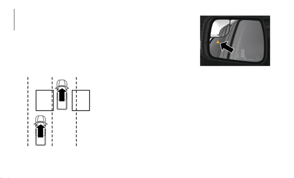
80
SAFETY
AUXILIARY DRIVING
SYSTEMS
Blind Spot Monitoring (BSM) — If
Equipped
The Blind Spot Monitoring (BSM) system
uses two radar-based sensors, located inside
the taillights, to detect highway licensable
vehicles (automobiles, trucks, motorcycles,
etc.) that enter the blind spot zones from the
rear/front/side of the vehicle.
Rear Detection Zones
When the vehicle is started, the BSM
warning l
ight will momentarily illuminate in
both outside rearview mirrors to let the driver
know that the system is operational. The
BSM system sensors operate when the
vehicle is in any forward gear or REVERSE
and enters stand-by mode when the vehicle
is in PARK.
The BSM detection zone covers approxi-
mately one lane width on both sides of the
vehicle 1
2 ft (3.8 m). The zone length starts
at the ou
tside rear view mirror and extends
approximately 10
ft (3 m) beyond the rear
bumper of
the vehicle. The BSM system
monitors the detection zones on both sides
of the vehicle when the vehicle speed
reaches approximately 6
mph (10 km/h) or
higher an
d will alert the driver of vehicles in
these areas.
The BSM system notifies the driver of
objects i
n the detection zones by illumi-
nating the BSM warning light located in the
o
utside m
irrors in addition to sounding an
audible (chime) alert and reducing the radio
volume.
Refer to “Modes Of Operation” in this
section f
or further information.
Blind Spot Warning Light
For information on how Blind Spot Moni-
toring functions when pulling a trailer, refer
t
o “Trail
er Merge Assist” in “Blind Spot
Monitoring” in the Owner’s Manual.
Rear Cross Path (RCP)
The Rear Cross Path (RCP) feature is
intended to aid the driver when backing out
of parking spaces where their vision of
oncoming vehicles may be blocked. Proceed
slowly and cautiously out of the parking
space until the rear end of the vehicle is
exposed. The RCP system will then have a

81
clear view of the cross traffic and if an
oncoming vehicle is detected, alert the
driver.
RCP monitors the rear detection zones on
both side
s of the vehicle, for objects that are
moving toward the side of the vehicle with a
minimum speed of approximately 3
mph
(5 km/h),
to objects moving a maximum of
approxima
tely 20 mph (32 km/h), such as in
parking l
ot situations.
NOTE:
In a parking lot situation, oncoming vehicles
c
an be ob
scured by vehicles parked on either
side. If the sensors are blocked by other
structures or vehicles, the system will not be
able to alert the driver.
When RCP is on and the vehicle is in
REVERSE,
the driver is alerted using both
the visual and audible alarms, including
reducing the radio volume.
Modes Of Operation
Three selectable modes of operation are
available in the Uconnect System.
Refer to “Uconnect Settings” in “Multi-
media” in the Owner’s Manual for further
i
nformati
on.
Blind Spot Alert Lights Only
When operating in Blind Spot Alert mode,
t
he BSM s
ystem will provide a visual alert in
the appropriate side view mirror based on a
detected object. However, when the system
is operating in Rear Cross Path (RCP) mode,
the system will respond with both visual and
audible alerts when a detected object is
present. Whenever an audible alert is
requested, the radio is muted.
Blind Spot Alert Lights/Chime
When operating in Blind Spot Alert Lights/
Chime mod
e, the BSM system will provide a
visual alert in the appropriate side view
mirror based on a detected object. If the turn
signal is then activated, and it corresponds
to an alert present on that side of the vehicle,
an audible chime will also be sounded.
Whenever a turn signal and detected object
are present on the same side at the same
time, both the visual and audible alerts will
be issued. In addition to the audible alert the
radio (if on) will also be muted.
NOTE:
Whenever an audible alert is requested by
t
he BSM s
ystem, the radio is also muted.
When the system is in RCP, the system shall
respond w
ith both visual and audible alerts
when a detected object is present. Whenever
an audible alert is requested, the radio is
also muted. Turn/hazard signal status is
ignored; the RCP state always requests the
chime.
WARNING!
Rear Cross Path Detection (RCP) is not a
back up aid system. It is intended to be
used to help a driver detect an oncoming
vehicle in a parking lot situation. Drivers
must be careful when backing up, even
when using RCP. Always check carefully
behind your vehicle, look behind you, and
be sure to check for pedestrians, animals,
other vehicles, obstructions, and blind
spots before backing up. Failure to do so
can result in serious injury or death.

SAFETY
82
Blind Spot Alert Off
When the BSM system is turned off there will
be no vis
ual or audible alerts from either the
BSM, RCP, or Trailer Merge Assist systems.
NOTE:
The BSM system will store the current oper-
ating mode when the vehicle is shut off.
Each time
the vehicle is started the previ-
ously stored mode will be recalled and used.
General Information
The following regulatory statement applies to
all Radio Frequency (RF) devices equipped in
this vehicle:
This device complies with Part 15 of the FCC
Rules and
with Industry Canada
license-exempt RSS standard(s). Operation is
subject to the following two conditions:
1. This device may not cause harmful interfer-
ence.
2. T
hi
s device must accept any interference
received
, including interference that may
cause undesired operation.
NOTE:
Changes or modifications not expressly
approved
by the party responsible for compli-
ance could void the user’s authority to
o
perate t
he equipment.
Forward Collision Warning (FCW) With
Mitigation — If Equipped
The Forward Collision Warning (FCW) system
provides the driver with audible, visual warn-
ings (within the instrument cluster display),
a
nd may a
pply a haptic warning in the form
of a brake jerk, to warn the driver when it
detects a potential frontal collision. The
warnings are intended to provide the driver
with enough time to react, avoid or mitigate
the potential collision.
NOTE:
FCW monitors the information from the
forward l
ooking sensors as well as Electronic
Brake Controller (EBC), to calculate the
probability of a forward collision. When the
system determines that a forward collision is
probable, the driver will be provided with
audible and visual warnings as well as a
possible haptic warning in the form of a
brake jerk.
If the driver does not take action based upon
these pro
gressive warnings, then the system
will provide a limited level of active braking
to help slow the vehicle and mitigate the
potential forward collision. If the driver
reacts to the warnings by braking and the
system determines that the driver intends to
avoid the collision by braking but has not
applied sufficient brake force, the system
will compensate and provide additional
brake force as required.
If a FCW with Mitigation event begins at a
speed bel
ow 32 mph (52 km/h), the system
may provi
de the maximum braking possible
to mitigate the potential forward collision. If
the Forward Collision Warning with Mitiga
-
tion event stops the vehicle completely, the
system wi
ll hold the vehicle at standstill for
two seconds and then release the brakes.
FCW Message
When the system determines a collision with
the vehicle in front of you is no longer prob-
able, the warning message will be deacti-
vated.
83
NOTE:
The minimum speed for FCW activation is
3 mph (5 km/h).
The FCW alerts may be triggered on
objects other than vehicles such as guard
rails or sign posts based on the course
prediction. This is expected and is a part
of normal FCW activation and function
-
ality.
It is unsafe to test the FCW system. To
prevent such misuse of the system, after
four Active Braking events within a key
cycle, the Active Braking portion of FCW
will be deactivated until the next key
cycle.
The FCW system is intended for on-road
use only. If the vehicle is taken off-road,
the FCW system should be deactivated to
prevent unnecessary warnings to the
surroundings.
FCW may not react to irrelevant objects
such as overhead objects, ground reflec-
tions, objects not in the path of the
v
ehicle,
stationary objects that are far
away, oncoming traffic, or leading vehicles
with the same or higher rate of speed.
“FCW will be disabled like ACC, with the
unavailable screens.
Turning FCW On or Off
The FCW button is located in the Uconnect
display in the control settings. Refer to
“Uconnect Settings” in “Multimedia” in the
Owner's Manual for further information.
To turn the FCW system on, press the
forward collision button once to turn the
system on.
To turn the FCW system off, press the
forward collision button once to turn the
system off.
NOTE:
When the FCW is “on”, this allows the
system to warn the driver of a possible
collision with the vehicle in front.
When the FCW is “off” prevents the
system from warning the driver of a
possible collision with the vehicle in front.
If the FCW is set to “off”, “FCW OFF" will
be displayed in the instrument cluster
display.
When FCW status is set to “Only Warning”
prevents the system from providing limited
active braking, or additional brake support
if the driver is not braking adequately in
the event of a potential frontal collision.
When FCW status is set to “Warning and
Braking” this allows the system to warn
the driver of a possible collision with the
vehicle in front using audible/visual warn
-
ings and it applies autonomous braking.
The system will retain the last setting
selected by the driver after ignition shut-
down.
FCW Braking Status And Sensitivity
The FCW sensitivity and Active Braking
status are programmable through the Ucon-
nect System. Refer to “Uconnect Settings”
i
n “Multi
media” in the Owner's Manual for
further information.
Far
When the sensitivity of FCW is set to the
“Far” setting and the system status is
“Warning and Braking”, this allows the
WARNING!
Forward Collision Warning (FCW) is not
intended to avoid a collision on its own,
nor can FCW detect every type of potential
collision. The driver has the responsibility
to avoid a collision by controlling the
vehicle via braking and steering. Failure to
follow this warning could lead to serious
injury or death.

SAFETY
84
system to warn the driver of a possible
more distant collisions with the vehicle
in front using audible/visual warnings.
More cautious drivers that do not mind
frequent warnings may prefer this
setting.
Medium
When the sensitivity of FCW is set to the
“Medium” setting and the system status
is “Warning and Braking”, this allows
the system to warn the driver of a
possible collision with the vehicle in
front using audible/visual warnings.
Near
When the sensitivity of FCW is set to the
“Near” setting and the system status is
“Warning and Braking”, this allows the
system to warn the driver of a possible
closer collisions with the vehicle in front
using audible/visual warnings.
This setting provides less reaction time
than the “Far” and “Medium” settings,
which allows for a more dynamic driving
experience.
More dynamic or aggressive drivers that
want to avoid frequent warnings may
prefer this setting.
FCW Limited Warning
If the instrument cluster displays “ACC/FCW
Limited Functionality” or “ACC/FCW Limited
Functionality Clean Front Windshield”
momentarily, there may be a condition that
limits FCW functionality. Although the
vehicle is still drivable under normal condi
-
tions, the active braking may not be fully
a
vailable.
Once the condition that limited
the system performance is no longer present,
the system will return to its full performance
state. If the problem persists, see an autho
-
rized dealer.
Service FCW Warning
If the system turns off, and the instrument
cluster displays:
ACC/FCW Unavailable Service Required
Cruise/FCW Unavailable Service Required
This indicates there is an internal system
fault. Alt
hough the vehicle is still drivable
under normal conditions, have the system
checked by an authorized dealer.
General Information
The following regulatory statement applies to
all Radio Frequency (RF) devices equipped
in this vehicle:
This device complies with Part 15 of the FCC
Rules and
with Industry Canada
license-exempt RSS standard(s). Operation
is subject to the following two conditions:
1. This device may not cause harmful inter-
ference.
2.
This device must accept any interference
received,
including interference that may
cause undesired operation.
NOTE:
Changes or modifications not expressly
approved b
y the party responsible for compli-
ance could void the user’s authority to
o
perate th
e equipment.
Tire Pressure Monitoring System (TPMS)
The Tire Pressure Monitor System (TPMS)
will warn the driver of a low tire pressure
based on the vehicle recommended cold
placard pressure.

85
(Continued)
NOTE:
The TPMS Warning Light will illuminate in
the instr
ument cluster and a chime will
sound when tire pressure is low in one or
more of the four active road tires. In addi
-
tion, the instrument cluster will display a
graphic s
howing the pressure values of each
tire with the low tire pressure values in a
different color, or the Uconnect radio will
display a TPMS message, when this occurs
you must increase the tire pressure to the
recommended cold placard pressure in order
for the TPMS Warning Light to turn off.
The tire pressure will vary with temperature
by about
1 psi (7 kPa) for every 12°F
(6.5°C). This means that when the outside
temperature decreases, the tire pressure will
decrease. Tire pressure should always be set
based on cold inflation tire pressure. This is
defined as the tire pressure after the vehicle
has not been driven for at least three hours,
or driven less than 1
mile (1.6 km) after a
three hou
r period. The cold tire inflation
pressure must not exceed the maximum
inflation pressure molded into the tire side
-
wall. Refer to “Tires” in “Servicing And
Maintenan
ce” for information on how to
properly inflate the vehicle’s tires. The tire
pressure will also increase as the vehicle is
driven - this is normal and there should be no
adjustment for this increased pressure.
The TPMS will warn the driver of a low tire
pressure
if the tire pressure falls below the
low-pressure warning limit for any reason,
including low temperature effects and
natural pressure loss through the tire.
The TPMS will continue to warn the driver of
low tire
pressure as long as the condition
exists, and will not turn off until the tire pres
-
sure is at or above the recommended cold
placard p
ressure. Once the low TPMS
Warning Light illuminates, you must
increase the tire pressure to the recom
-
mended cold placard pressure in order for
the TPMS
Warning Light to turn off. The
system will automatically update and the
TPMS Warning Light will turn off once the
system receives the updated tire pressures.
The vehicle may need to be driven for up to
20
minutes above 15 mph (24 km/h) in
order for
the TPMS to receive this informa-
tion.
NOTE:
When filling warm tires, the tire pressure
m
ay need
to be increased up to an additional
4 psi (28 kPa) above the recommended cold
placard pressure in order to turn the TPMS
Warning Light off.
For example, your vehicle may have a recom-
mended cold (parked for more than three
h
ours) pl
acard pressure of 30 psi (207 kPa).
If the ambient temperature is 68°F (20°C)
and the measured tire pressure is 27 psi
(186 kPa), a temperature drop to 20°F
(-7°C) will decrease the tire pressure to
approximately 23 psi (158 kPa). This tire
pressure is sufficiently low enough to turn on
the TPMS Warning Light. Driving the vehicle
may cause the tire pressure to rise to approx
-
imately 27 psi (186 kPa), but the TPMS
Warning L
ight will still be on. In this situa-
tion, the TPMS Warning Light will turn off
o
nly afte
r the tires are inflated to the
vehicle’s recommended cold placard pres
-
sure value.
CAUTION!
The TPMS has been optimized for the
original equipment tires and wheels.
TPMS pressures and warning have been
established for the tire size equipped on
your vehicle. Undesirable system opera
-
tion or sensor damage may result when
using rep
lacement equipment that is not
of the same size, type, and/or style.
Aftermarket wheels can cause sensor
damage.
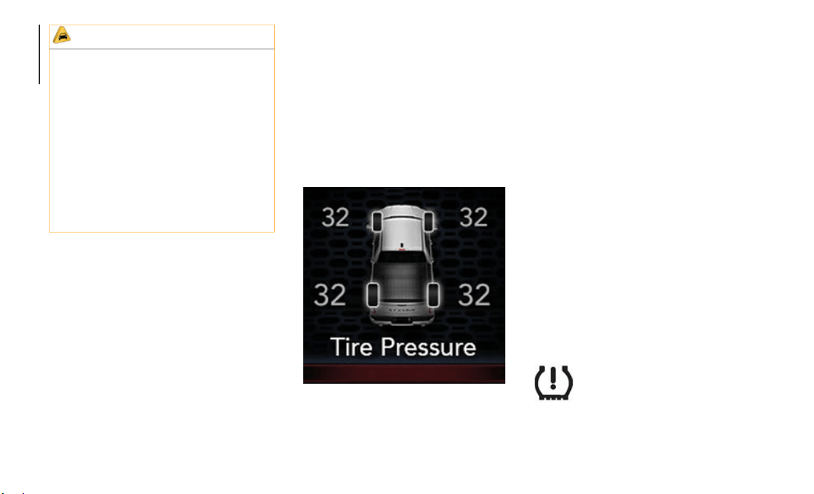
SAFETY
86
NOTE:
The TPMS is not intended to replace normal
tire care and maintenance or to provide
warning of a tire failure or condition.
If your vehicle is not equipped with the Tire
Fill Alert feature the TPMS should not be
used as a tire pressure gauge while
adjusting your tire pressure.
Driving on a significantly under-inflated tire
causes the tire to overheat and can lead to
tire failure. Under-inflation also reduces
fuel efficiency and tire tread life, and may
affect the vehicle’s handling and stopping
ability.
The TPMS is not a substitute for proper tire
maintenance, and it is the driver’s responsi-
bility to maintain correct tire pressure using
a
n accura
te tire pressure gauge, even if
under-inflation has not reached the level to
trigger illumination of the TPMS Warning
Light.
Seasonal temperature changes will affect
tire pressure, and the TPMS will monitor
the actual tire pressure in the tire.
Example: Tire Pressure Monitor Display
The Tire Pressure Monitor System (TPMS)
uses wire
less technology with wheel rim
mounted electronic sensors to monitor tire
pressure levels. Sensors, mounted to each
wheel as part of the valve stem, transmit tire
pressure readings to the receiver module.
NOTE:
It is particularly important for you to check
the tire
pressure in all of the tires on your
vehicle monthly and to maintain the proper
pressure.
The TPMS consists of the following compo-
nents:
Receiver module
Four tire pressure monitoring sensors
Various tire pressure monitoring system
messages, which display in the instrument
cluster
Tire Pressure Monitoring System Warning
Light
Tire Pressure Monitoring Low Pressure
Warnings
The “Tire Pressure Monitoring Tell-
tale Light” will illuminate in the
instrumen
t cluster and a chime will
sound when tire pressure is low in
one or more of the four active road tires. In
addition, the instrument cluster will display
a graphic showing the pressure values of
Using aftermarket tire sealants may
cause the Tire Pressure Monitoring
System (TPMS) sensor to become inop
-
erable. After using an aftermarket tire
sealant i
t is recommended that you take
your vehicle to an authorized dealership
to have your sensor function checked.
After inspecting or adjusting the tire
pressure always reinstall the valve stem
cap. This will prevent moisture and dirt
from entering the valve stem, which
could damage the TPMS sensor.
CAUTION! (Continued)
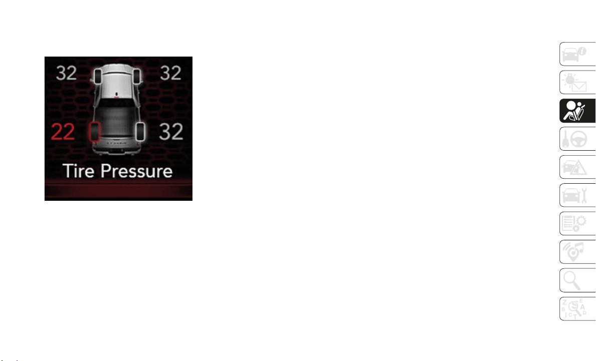
87
each tire with the low tire pressure values in
a different color. An "Inflate to XX" message
will also be displayed.
Example: Low Tire Pressure Display
Should this occur, you should stop as soon as
possible
and inflate the tires with a low pres-
sure condition (those in a different color in
t
he instr
ument cluster graphic) to the
vehicle’s recommended cold placard pres
-
sure inflation value as shown in the "Inflate
to XX" me
ssage. Once the system receives
the updated tire pressures, the system will
automatically update, the graphic display in
the instrument cluster will return to it’s orig
-
inal color, and the “Tire Pressure Monitoring
Telltale
Light” will turn off. The vehicle may
need to be driven for up to 20 minutes above
15 mph (24
km/h) in order for the TPMS to
receive t
his information.
NOTE:
When filling warm tires, the tire pressure
m
ay need
to be increased up to an additional
4 psi (28 kPa) above the recommended cold
placard pressure in order to turn the Tire
Pressure Monitoring Telltale Light off.
Service TPMS Warning
If a system fault is detected, the “Tire Pres-
sure Monitoring Telltale Light” will flash on
and off f
or 75 seconds and then remain on
solid. The system fault will also sound a
chime. In addition, the instrument cluster
will display a "SERVICE TPM SYSTEM"
message for a minimum of five seconds and
then display dashes (- -) in place of the pres
-
sure value to indicate which sensor is not
being rec
eived.
If the ignition switch is cycled, this sequence
will repe
at, providing the system fault still
exists. If the system fault no longer exists,
the “Tire Pressure Monitoring Telltale Light”
will no longer flash, and the "SERVICE TPM
SYSTEM" message will no longer display,
and a pressure value will display in place of
the dashes. A system fault can occur due to
any of the following:
Signal interference due to electronic
devices or driving next to facilities emit-
ting the same radio frequencies as the
T
PM senso
rs.
Installing aftermarket window tinting that
contains materials that may block radio
wave signals.
Accumulation of snow or ice around the
wheels or wheel housings.
Using tire chains on the vehicle.
Using wheels/tires not equipped with TPM
sensors.
A system fault may occur due to an incorrect
TPM senso
r location condition. When a
system fault occurs due to an incorrect TPM
sensor location, the “Tire Pressure Moni
-
toring Telltale Light” will flash on and off for
75 second
s and then remain on solid. The
system fault will also sound a chime. In addi
-
tion, the instrument cluster will display a
“Tire Pre
ssure Temporarily Unavailable”
message in place of the tire pressure display
screen. If the ignition switch is cycled, this
sequence will repeat, providing the system
fault still exists. If the system fault no longer

SAFETY
88
exists, the “Tire Pressure Monitoring Telltale
Light” will no longer flash and the tire pres-
sure display screen will be displayed showing
t
he tire
pressure values the correct locations.
Vehicles With Non Matching Full Size Spare Or
Compact S
pare
The non matching full size spare or
compact spare tire does not have a TPM
sensor. Therefore, the TPMS will not
monitor the pressure in the non matching
full size spare or compact spare tire.
If you install the non matching full size
spare or compact spare tire in place of a
road tire that has a pressure below the
low-pressure warning limit, upon the next
ignition switch cycle, the TPM Telltale
Light and a “LOW TIRE” message will
remain ON and a chime will sound. In
addition, the graphic in the instrument
cluster will still display a pressure value in
a different color and an “Inflate to XX”
message.
After driving the vehicle for up to
20 minutes above 15 mph (24 km/h), the
TPM Tellt
ale Light will flash on and off for
75 seconds and then remain on solid. In
addition, the instrument cluster will
display a "SERVICE TPM SYSTEM"
message for a minimum of five seconds
and then display dashes (- -) in place of
the pressure value.
For each subsequent ignition switch cycle,
a chime will sound, the TPM Telltale Light
will flash on and off for 75 seconds and
then remain on solid, and the instrument
cluster will display a "SERVICE TPM
SYSTEM" message for a minimum of five
seconds and then display dashes (- -) in
place of the pressure value.
Once you repair or replace the original
road tire and reinstall it on the vehicle in
place of the non matching full size spare
or compact spare, the TPMS will update
automatically. In addition, the TPM Tell
-
tale Light will turn OFF and the graphic in
the instr
ument cluster will display a new
pressure value instead of dashes (- -), as
long as no tire pressure is below the
low-pressure warning limit in any of the
four active road tires. The vehicle may
need to be driven for up to 20
minutes
above 15 m
ph (24 km/h) in order for the
TPMS to r
eceive this information.
Tire Fill Alert
This feature notifies the user when the
placard tire pressure is attained while
inflating or deflating the tire.
The customer may choose to disable or
enable th
e Tire Fill Alert feature through use
of the customer settings in the radio.
NOTE:
Only one tire can be filled at a time when
using the Tire Fill Alert system.
The Tire Fill Alert feature cannot be
entered if an existing TPM system fault is
set to “active” or if the system is in deac
-
tivation mode (if equipped).
The system will be activated when the TPM
receiver
module detects a change in tire
pressure. The ignition must be in the RUN
mode, with the transmission in PARK (P).
NOTE:
It is not required to have the engine running
to enter
Tire Fill Alert mode.
The hazard lamps will come on to confirm
the vehic
le is in Tire Fill Alert mode.
When Tire Fill Alert Mode is entered, the tire
pressure
display screen will be displayed in
the instrument cluster.

89
Operation:
The horn will chirp to let the user know
when to stop filling the tire, when it
reaches recommended pressure.
The horn will chirp three times if the tire
is over filled and will continue to chirp
every five seconds if the user continues to
inflate the tire.
The horn will chirp once again when
enough air is let out to reach proper infla-
tion level.
The horn will also chirp three times if the
tire is then under-inflated and will
continue to chirp every five seconds if the
user continues to deflate the tire.
General Information
This device complies with Part 15 of the FCC
rules and RSS 210 of Industry Canada.
Operation is subject to the following condi
-
tions:
1. This device may not cause harmful inter-
ference.
2
. This device must accept any interference
received
, including interference that may
cause undesired operation.
NOTE:
Changes or modifications not expressly
a
pproved
by the party responsible for compli-
ance could void the user’s authority to
o
perate t
he equipment.
OCCUPANT RESTRAINT
SYSTEMS
Some of the most important safety features
in your vehicle are the restraint systems:
Occupant Restraint Systems Features
Seat Belt Systems
Supplemental Restraint Systems (SRS)
Air Bags
Child Restraints
Some of the safety features described in this
section m
ay be standard equipment on some
models, or may be optional equipment on
others. If you are not sure, ask an authorized
dealer.
Important Safety Precautions
Please pay close attention to the information
in this section. It tells you how to use your
restraint system properly, to keep you and
your passengers as safe as possible.
Here are some simple steps you can take to
minimize
the risk of harm from a deploying
air bag:
1. Children 12 years old and under should
always r
ide buckled up in the rear seat of
a vehicle with a rear seat.
2. A child who is not big enough to wear the
vehicle
seat belt properly (Refer to “Child
Restraints” in this section for further
information) must be secured in the
appropriate child restraint or belt-posi
-
tioning booster seat in a rear seating
position.
3
. If a child from 2 to 12 years old (not in a
rear-fac
ing child restraint) must ride in
the front passenger seat, move the seat
as far back as possible and use the
proper child restraint (Refer to “Child
Restraints” in this section for further
information).
4. Never allow children to slide the shoulder
belt beh
ind them or under their arm.
5. You should read the instructions
provided
with your child restraint to make
sure that you are using it properly.
6. All occupants should always wear their
lap and shoulder belts properly.

SAFETY
90
7. The driver and front passenger seats
should be moved back as far as practical
to allow the front air bags room to inflate.
8. Do not lean against the door or window.
If your
vehicle has side air bags, and
deployment occurs, the side air bags will
inflate forcefully into the space between
occupants and the door and occupants
could be injured.
9. If the air bag system in this vehicle needs
to be mo
dified to accommodate a
disabled person, refer to the “Customer
Assistance” section for customer service
contact information.
Seat Belt Systems
Buckle up even though you are an excellent
driver, even on short trips. Someone on the
road may be a poor driver and could cause a
collision that includes you. This can happen
far away from home or on your own street.
Research has shown that seat belts save
lives, an
d they can reduce the seriousness of
injuries in a collision. Some of the worst inju
-
ries happen when people are thrown from the
vehicle.
Seat belts reduce the possibility of
ejection and the risk of injury caused by
striking the inside of the vehicle. Everyone in
a motor vehicle should be belted at all times.
Enhanced Seat Belt Use Reminder System
(BeltAlert)
Driver And Passenger BeltAlert — If Equipped
BeltAlert is a feature intended to remind
the driver and outboard front seat passenger
(if equip
ped with outboard front passenger
seat BeltAlert) to buckle their seat belts. The
Belt Alert feature is active whenever the igni
-
tion switch is in the START or ON/RUN posi-
tion.
Initial Indication
If the driver is unbuckled when the ignition
switch is
first in the START or ON/RUN posi-
tion, a chime will signal for a few seconds. If
t
he drive
r or outboard front seat passenger (if
equipped with outboard front passenger seat
BeltAlert) is unbuckled when the ignition
switch is first in the START or ON/RUN posi
-
tion the Seat Belt Reminder Light will turn
on and re
main on until both outboard front
seat belts are buckled. The outboard front
passenger seat BeltAlert is not active when
an outboard front passenger seat is unoccu
-
pied.
BeltAlert Warning Sequence
The BeltAlert warning sequence is activated
w
hen the
vehicle is moving above a specified
vehicle speed range and the driver or
outboard front seat passenger is unbuckled
(if equipped with outboard front passenger
seat BeltAlert) (the outboard front passenger
seat BeltAlert is not active when the
outboard front passenger seat is unoccu
-
pied). The BeltAlert warning sequence starts
by blinki
ng the Seat Belt Reminder Light and
sounding an intermittent chime. Once the
BeltAlert warning sequence has completed,
the Seat Belt Reminder Light will remain on
until the seat belts are buckled. The
WARNING!
Never place a rear-facing child restraint
in front of an air bag. A deploying
passenger front air bag can cause death
or serious injury to a child 12 years or
younger, including a child in a
rear-facing child restraint.
Never install a rear-facing child restraint
in the front seat of a vehicle. Only use a
rear-facing child restraint in the rear
seat. If the vehicle does not have a rear
seat, do not transport a rear-facing child
restraint in that vehicle.
91
(Continued)
(Continued)
BeltAlert warning sequence may repeat
based on vehicle speed until the driver and
occupied outboard front seat passenger seat
belts are buckled. The driver should instruct
all occupants to buckle their seat belts.
Change Of Status
If the driver or outboard front seat passenger
(if equipp
ed with outboard front passenger
seat BeltAlert) unbuckles their seat belt
while the vehicle is traveling, the BeltAlert
warning sequence will begin until the seat
belts are buckled again.
The outboard front passenger seat BeltAlert
is not act
ive when the outboard front
passenger seat is unoccupied. BeltAlert may
be triggered when an animal or other items
are placed on the outboard front passenger
seat or when the seat is folded flat (if
equipped). It is recommended that pets be
restrained in the rear seat (if equipped) in
pet harnesses or pet carriers that are secured
by seat belts, and cargo is properly stowed.
BeltAlert can be activated or deactivated by
an authori
zed dealer. FCA US LLC does not
recommend deactivating BeltAlert.
NOTE:
If BeltAlert has been deactivated and the
driver or
outboard front seat passenger (if
equipped with outboard front passenger seat
BeltAlert) is unbuckled the Seat Belt
Reminder Light will turn on and remain on
until the driver and outboard front seat
passenger seat belts are buckled.
Lap/Shoulder Belts
All seating positions in your vehicle are
equipped with lap/shoulder belts.
The seat belt webbing retractor will lock only
during ver
y sudden stops or collisions. This
feature allows the shoulder part of the seat
belt to move freely with you under normal
conditions. However, in a collision the seat
belt will lock and reduce your risk of striking
the inside of the vehicle or being thrown out
of the vehicle.
WARNING!
Relying on the air bags alone could lead
to more severe injuries in a collision. The
air bags work with your seat belt to
restrain you properly. In some collisions,
the air bags won’t deploy at all. Always
wear your seat belt even though you have
air bags.
In a collision, you and your passengers
can suffer much greater injuries if you
are not properly buckled up. You can
strike the interior of your vehicle or other
passengers, or you can be thrown out of
the vehicle. Always be sure you and
others in your vehicle are buckled up
properly.
It is dangerous to ride in a cargo area,
inside or outside of a vehicle. In a colli-
sion, people riding in these areas are
m
ore likel
y to be seriously injured or
killed.
Do not allow people to ride in any area of
your vehicle that is not equipped with
seats and seat belts.
Be sure everyone in your vehicle is in a
seat and using a seat belt properly.
Occupants, including the driver, should
always wear their seat belts whether or
not an air bag is also provided at their
seating position to minimize the risk of
severe injury or death in the event of a
crash.
WARNING! (Continued)

SAFETY
92
(Continued)
(Continued)
Lap/Shoulder Belt Operating Instructions
1. Enter the vehicle and close the door. Sit
back and adjust the seat.
2. The seat belt latch plate is above the
back of
the front seat, and next to your
arm in the rear seat (for vehicles
equipped with a rear seat). Grasp the
latch plate and pull out the seat belt.
Slide the latch plate up the webbing as
far as necessary to allow the seat belt to
go around your lap.
Wearing your seat belt incorrectly could
make your injuries in a collision much
worse. You might suffer internal injuries,
or you could even slide out of the seat
belt. Follow these instructions to wear
your seat belt safely and to keep your
passengers safe, too.
Two people should never be belted into a
single seat belt. People belted together
can crash into one another in a collision,
hurting one another badly. Never use a
lap/shoulder belt or a lap belt for more
than one person, no matter what their
size.
WARNING!
A lap belt worn too high can increase the
risk of injury in a collision. The seat belt
forces won’t be at the strong hip and
pelvic bones, but across your abdomen.
Always wear the lap part of your seat belt
as low as possible and keep it snug.
WARNING! (Continued)
A twisted seat belt may not protect you
properly. In a collision, it could even cut
into you. Be sure the seat belt is flat
against your body, without twists. If you
can’t straighten a seat belt in your
vehicle, take it to an authorized dealer
immediately and have it fixed.
A seat belt that is buckled into the wrong
buckle will not protect you properly. The
lap portion could ride too high on your
body, possibly causing internal injuries.
Always buckle your seat belt into the
buckle nearest you.
A seat belt that is too loose will not
protect you properly. In a sudden stop,
you could move too far forward,
increasing the possibility of injury. Wear
your seat belt snugly.
A seat belt that is worn under your arm is
dangerous. Your body could strike the
inside surfaces of the vehicle in a colli
-
sion, increasing head and neck injury. A
seat belt
worn under the arm can cause
internal injuries. Ribs aren’t as strong as
shoulder bones. Wear the seat belt over
your shoulder so that your strongest
bones will take the force in a collision.
WARNING! (Continued)
A shoulder belt placed behind you will
not protect you from injury during a colli-
sion. You are more likely to hit your head
i
n a coll
ision if you do not wear your
shoulder belt. The lap and shoulder belt
are meant to be used together.
A frayed or torn seat belt could rip apart
in a collision and leave you with no
protection. Inspect the seat belt system
periodically, checking for cuts, frays, or
loose parts. Damaged parts must be
replaced immediately. Do not disas
-
semble or modify the seat belt system.
S
eat belt
assemblies must be replaced
after a collision.
WARNING! (Continued)
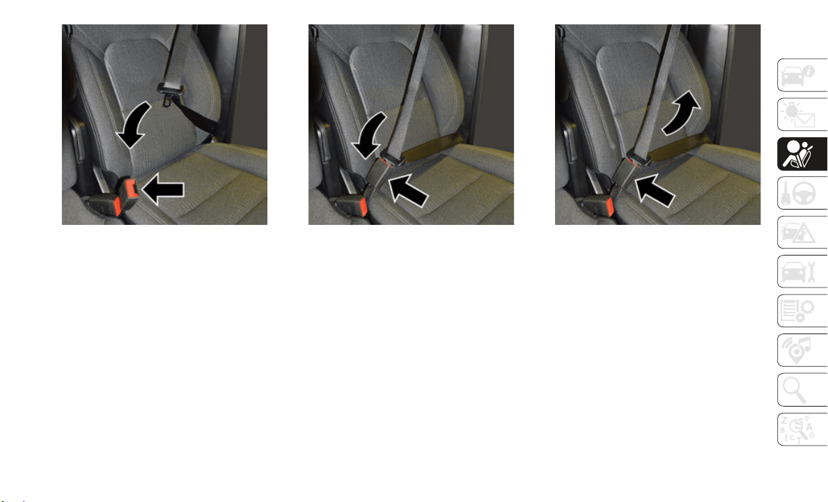
93
Pulling Out The Latch Plate
3. When the seat belt is long enough to fit,
insert t
he latch plate into the buckle until
you hear a “click.”
Inserting Latch Plate Into Buckle
4. Position the lap belt so that it is snug and
lies low across your hips, below your
abdomen. To remove slack in the lap belt
portion, pull up on the shoulder belt. To
loosen the lap belt if it is too tight, tilt the
latch plate and pull on the lap belt. A
snug seat belt reduces the risk of sliding
under the seat belt in a collision.
Positioning The Lap Belt
5. Position the shoulder belt across the
shoulder and chest with minimal, if any
slack so that it is comfortable and not
resting on your neck. The retractor will
withdraw any slack in the shoulder belt.
6. To release the seat belt, push the red
button o
n the buckle. The seat belt will
automatically retract to its stowed posi
-
tion. If necessary, slide the latch plate
down the
webbing to allow the seat belt
to retract fully.
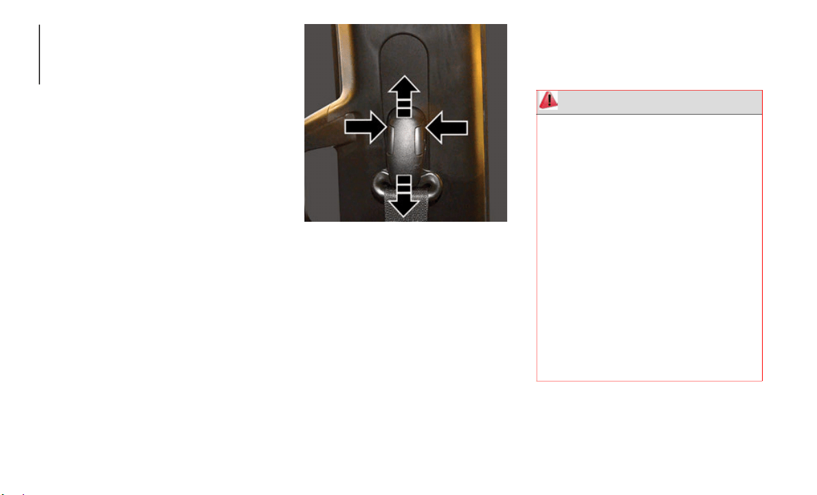
SAFETY
94
Lap/Shoulder Belt Untwisting Procedure
Use the following procedure to untwist a
twisted lap/shoulder belt.
1. Position the latch plate as close as
possible
to the anchor point.
2. At about 6 to 12 inches (
15 to 30 cm)
above the latch plate, grasp and twist the
seat belt webbing 180 degrees to create
a fold that begins immediately above the
latch plate.
3. Slide the latch plate upward over the
folded we
bbing. The folded webbing
must enter the slot at the top of the latch
plate.
4. Continue to slide the latch plate up until
it clears
the folded webbing and the seat
belt is no longer twisted.
Adjustable Upper Shoulder Belt Anchorage
In the driver and outboard front passenger
seats, the top of the shoulder belt can be
adjusted upward or downward to position the
seat belt away from your neck. Push or
squeeze the anchorage button to release the
anchorage, and move it up or down to the
position that serves you best.
Adjustable Anchorage
As a guide, if you are shorter than average,
you will p
refer the shoulder belt anchorage in
a lower position, and if you are taller than
average, you will prefer the shoulder belt
anchorage in a higher position. After you
release the anchorage button, try to move it
up or down to make sure that it is locked in
position.
NOTE:
The adjustable upper shoulder belt
anchorage
is equipped with an Easy Up
feature. This feature allows the shoulder belt
anchorage to be adjusted in the upward posi
-
tion without pushing or squeezing the
release bu
tton. To verify the shoulder belt
anchorage is latched, pull downward on the
shoulder belt anchorage until it is locked into
position.
Seat Belt Extender
If a seat belt is not long enough to fit prop-
erly, even when the webbing is fully extended
and the ad
justable upper shoulder belt
WARNING!
Wearing your seat belt incorrectly could
make your injuries in a collision much
worse. You might suffer internal injuries,
or you could even slide out of the seat
belt. Follow these instructions to wear
your seat belt safely and to keep your
passengers safe, too.
Position the shoulder belt across the
shoulder and chest with minimal, if any
slack so that it is comfortable and not
resting on your neck. The retractor will
withdraw any slack in the shoulder belt.
Misadjustment of the seat belt could
reduce the effectiveness of the safety
belt in a crash.
Always make all seat belt height adjust-
ments when the vehicle is stationary.
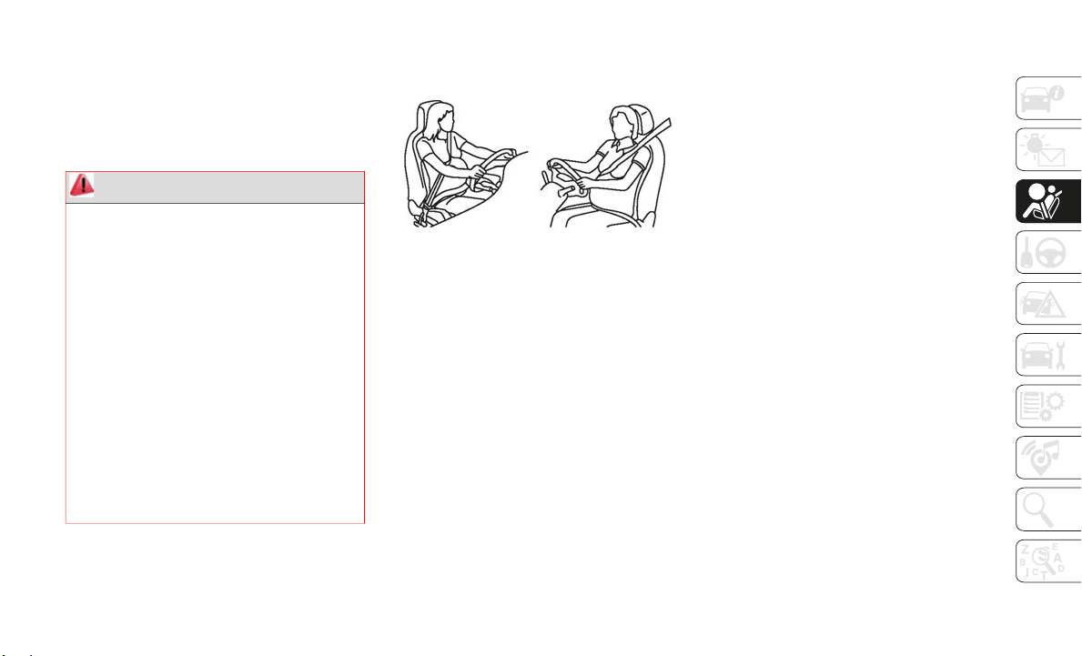
95
anchorage (if equipped) is in its lowest posi-
tion, an authorized dealer can provide you
with a Se
at Belt Extender. The Seat Belt
Extender should be used only if the existing
seat belt is not long enough. When the Seat
Belt Extender is not required for a different
occupant, it must be removed.
Seat Belts And Pregnant Women
Pregnant Women And Seat Belts
Seat belts must be worn by all occupants
including
pregnant women: the risk of injury
in the event of an accident is reduced for the
mother and the unborn child if they are
wearing a seat belt.
Position the lap belt snug and low below the
abdomen a
nd across the strong bones of the
hips. Place the shoulder belt across the
chest and away from the neck. Never place
the shoulder belt behind the back or under
the arm.
Seat Belt Pretensioner
The front outboard seat belt system is
equipped with pretensioning devices that are
designed to remove slack from the seat belt
in the event of a collision. These devices may
improve the performance of the seat belt by
removing slack from the seat belt early in a
collision. Pretensioners work for all size
occupants, including those in child
restraints.
NOTE:
These devices are not a substitute for proper
seat belt
placement by the occupant. The
seat belt still must be worn snugly and posi
-
tioned properly.
The pretensioners are triggered by the Occu-
pant Restraint Controller (ORC). Like the air
bags, the
pretensioners are single use items.
A deployed pretensioner or a deployed air
bag must be replaced immediately.
Energy Management Feature
The front outboard seat belt system is
equipped with an Energy Management
feature that may help further reduce the risk
of injury in the event of a collision. The seat
belt system has a retractor assembly that is
designed to release webbing in a controlled
manner.
WARNING!
ONLY use a Seat Belt Extender if it is
physically required in order to properly
fit the original seat belt system. DO NOT
USE the Seat Belt Extender if, when
worn, the distance between the front
edge of the Seat Belt Extender buckle
and the center of the occupant’s body is
LESS than 6
inches.
Using a Seat Belt Extender when not
needed can increase the risk of serious
injury or death in a collision. Only use
the Seat Belt Extender when the lap belt
is not long enough and only use in the
recommended seating positions.
Remove and store the Seat Belt Extender
when not needed.
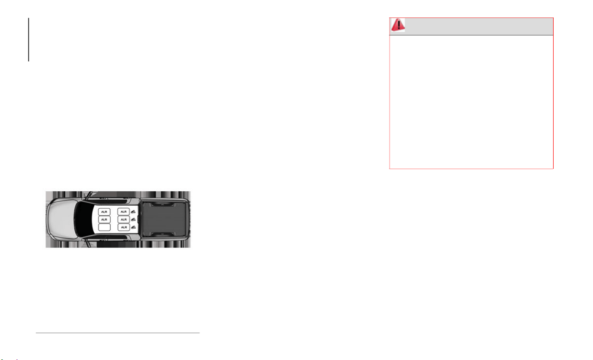
SAFETY
96
Switchable Automatic Locking Retractors
(ALR)
The seat belts in the passenger seating posi-
tions are equipped with a Switchable Auto-
matic Locking Retractor (ALR) which is used
t
o secure
a child restraint system. For addi-
tional information, refer to “Installing Child
R
estraint
s Using The Vehicle Seat Belt”
under the “Child Restraints” section of this
manual. The figure below illustrates the
locking feature for each seating position.
Automatic Locking Retractor (ALR) Locations
If the passenger seating position is equipped
with an A
LR and is being used for normal
usage, only pull the seat belt webbing out far
enough to comfortably wrap around the
occupant’s mid-section so as to not activate
the ALR. If the ALR is activated, you will
hear a clicking sound as the seat belt
retracts. Allow the webbing to retract
completely in this case and then carefully
pull out only the amount of webbing neces
-
sary to comfortably wrap around the occu-
pant’s mid-section. Slide the latch plate into
the buckl
e until you hear a "click."
In Automatic Locking Mode, the shoulder
belt is a
utomatically pre-locked. The seat
belt will still retract to remove any slack in
the shoulder belt. Use the Automatic
Locking Mode anytime a child restraint is
installed in a seating position that has a seat
belt with this feature. Children 12 years old
and under should always be properly
restrained in the rear seat of a vehicle with a
rear seat.
How To Engage The Automatic Locking Mode
1. B
uckle the combination lap and shoulder
belt.
2. Gr
asp the shoulder portion and pull
downward
until the entire seat belt is
extracted.
3. Allow the seat belt to retract. As the seat
belt ret
racts, you will hear a clicking
sound. This indicates the seat belt is now
in the Automatic Locking Mode.
ALR = Switchable Automatic Locking Re-
tractor
WARNING!
Never place a rear-facing child restraint
in front of an air bag. A deploying
passenger front air bag can cause death
or serious injury to a child 12 years or
younger, including a child in a
rear-facing child restraint.
Never install a rear-facing child restraint
in the front seat of a vehicle. Only use a
rear-facing child restraint in the rear
seat. If the vehicle does not have a rear
seat, do not transport a rear-facing child
restraint in that vehicle.

97
How To Disengage The Automatic Locking
Mode
Unbuckle the combination lap/shoulder belt
and allow
it to retract completely to disen-
gage the Automatic Locking Mode and acti-
vate the vehicle sensitive (emergency)
l
ocking mo
de.
Supplemental Restraint Systems (SRS)
Some of the safety features described in this
section may be standard equipment on some
models, or may be optional equipment on
others. If you are not sure, ask an authorized
dealer.
The air bag system must be ready to protect
you in a c
ollision. The Occupant Restraint
Controller (ORC) monitors the internal
circuits and interconnecting wiring associ
-
ated with the electrical Air Bag System
Components
. Your vehicle may be equipped
with the following Air Bag System Compo
-
nents:
Air Bag System Components
Occupant Restraint Controller (ORC)
Air Bag Warning Light
Steering Wheel and Column
Instrument Panel
Knee Impact Bolsters
Driver and Front Passenger Air Bags
Seat Belt Buckle Switch
Supplemental Side Air Bags
Front and Side Impact Sensors
Seat Belt Pretensioners
Seat Track Position Sensors
Occupant Classification System
Air Bag Warning Light
The ORC monitors the readiness of the
electronic parts of the air bag system when-
ever the ignition switch is in the START or
O
N/RUN pos
ition. If the ignition switch is in
the OFF position or in the ACC position, the
air bag system is not on and the air bags will
not inflate.
The ORC contains a backup power supply
system tha
t may deploy the air bag system
even if the battery loses power or it becomes
disconnected prior to deployment.
The ORC turns on the Air Bag Warning Light
in the ins
trument panel for approximately
four to eight seconds for a self-check when
the ignition switch is first in the ON/RUN
position. After the self-check, the Air Bag
Warning Light will turn off. If the ORC
detects a malfunction in any part of the
system, it turns on the Air Bag Warning
WARNING!
The seat belt assembly must be replaced
if the switchable Automatic Locking
Retractor (ALR) feature or any other seat
belt function is not working properly
when checked according to the proce
-
dures in the Service Manual.
Failure to replace the seat belt assembly
could increase the risk of injury in colli-
sions.
Do not use the Automatic Locking Mode
to restrain occupants who are wearing
the seat belt or children who are using
booster seats. The locked mode is only
used to install rear-facing or
forward-facing child restraints that have
a harness for restraining the child.

SAFETY
98
Light, either momentarily or continuously. A
single chime will sound to alert you if the
light comes on again after initial startup.
The ORC also includes diagnostics that will
illuminat
e the instrument panel Air Bag
Warning Light if a malfunction is detected
that could affect the air bag system. The
diagnostics also record the nature of the
malfunction. While the air bag system is
designed to be maintenance free, if any of
the following occurs, have an authorized
dealer service the air bag system immedi
-
ately.
The Air Bag Warning Light does not come
on during the four to eight seconds when
the ignition switch is first in the ON/RUN
position.
The Air Bag Warning Light remains on
after the four to eight-second interval.
The Air Bag Warning Light comes on inter-
mittently or remains on while driving.
NOTE:
If the speedometer, tachometer, or any
e
ngine re
lated gauges are not working, the
Occupant Restraint Controller (ORC) may
also be disabled. In this condition the air
bags may not be ready to inflate for your
protection. Have an authorized dealer service
the air bag system immediately.
Redundant Air Bag Warning Light
If a fault with the Air Bag Warning
Light is detected, which could
affect th
e Supplemental Restraint
System (SRS), the Redundant Air
Bag Warning Light will illuminate on the
instrument panel. The Redundant Air Bag
Warning Light will stay on until the fault is
cleared. In addition, a single chime will
sound to alert you that the Redundant Air
Bag Warning Light has come on and a fault
has been detected. If the Redundant Air Bag
Warning Light comes on intermittently or
remains on while driving have an authorized
dealer service the vehicle immediately.
For additional information regarding the
Redundant
Air Bag Warning Light refer to
“Getting To Know Your Instrument Panel”
section of this manual.
Front Air Bags
This vehicle has front air bags and lap/
shoulder belts for both the driver and front
passenger. The front air bags are a supple
-
ment to the seat belt restraint systems. The
driver fr
ont air bag is mounted in the center
of the steering wheel. The passenger front air
bag is mounted in the instrument panel,
above the glove compartment. The words
“SRS AIRBAG” or “AIRBAG” are embossed
on the air bag covers.
WARNING!
Ignoring the Air Bag Warning Light in your
instrument panel could mean you won’t
have the air bag system to protect you in a
collision. If the light does not come on as
a bulb check when the ignition is first
turned on, stays on after you start the
vehicle, or if it comes on as you drive, have
an authorized dealer service the air bag
system immediately.

99
(Continued)
(Continued)
Front Air Bag/Knee Bolster Locations
Driver And Passenger Front Air Bag Features
The Advanced Front Air Bag system has
multistage driver and front passenger air
bags. This system provides output appro
-
priate to the severity and type of collision as
determine
d by the Occupant Restraint
Controller (ORC), which may receive infor
-
mation from the front impact sensors (if
equipped)
or other system components.
The first stage inflator is triggered immedi-
ately during an impact that requires air bag
d
eploymen
t. A low energy output is used in
less severe collisions. A higher energy output
is used for more severe collisions.
This vehicle may be equipped with a driver
and/or fr
ont passenger seat belt buckle
switch that detects whether the driver or
front passenger seat belt is buckled. The seat
belt buckle switch may adjust the inflation
rate of the Advanced Front Air Bags.
This vehicle may be equipped with driver
and/or fr
ont passenger seat track position
sensors that may adjust the inflation rate of
the Advanced Front Air Bags based upon
seat position.
This vehicle is equipped with a right front
passenger
Occupant Classification System
(“OCS”) that is designed to provide
Passenger Advanced Front Air Bag output
appropriate to the occupant’s seated weight
input, as determined by the OCS.
1 — Driver And Passenger Front Air Bags
2 — Driver And Passenger Knee Impact
Bolsters
WARNING!
Being too close to the steering wheel or
instrume10nt panel during front air bag
deployment could cause serious injury,
including death. Air bags need room to
inflate. Sit back, comfortably extending
your arms to reach the steering wheel or
instrument panel.
Never place a rear-facing child restraint
in front of an air bag. A deploying
passenger front air bag can cause death
or serious injury to a child 12 years or
younger, including a child in a
rear-facing child restraint.
Never install a rear-facing child restraint
in the front seat of a vehicle. Only use a
rear-facing child restraint in the rear
seat. If the vehicle does not have a rear
seat, do not transport a rear-facing child
restraint in that vehicle.
WARNING! (Continued)
WARNING!
No objects should be placed over or near
the air bag on the instrument panel or
steering wheel because any such objects
could cause harm if the vehicle is in a
collision severe enough to cause the air
bag to inflate.

SAFETY
100
Front Air Bag Operation
Front Air Bags are designed to provide addi-
tional protection by supplementing the seat
belts. Fr
ont air bags are not expected to
reduce the risk of injury in rear, side, or roll
-
over collisions. The front air bags will not
deploy in
all frontal collisions, including
some that may produce substantial vehicle
damage — for example, some pole colli
-
sions, truck underrides, and angle offset
collision
s.
On the other hand, depending on the type
and locat
ion of impact, front air bags may
deploy in crashes with little vehicle front-end
damage but that produce a severe initial
deceleration.
Because air bag sensors measure vehicle
decelerat
ion over time, vehicle speed and
damage by themselves are not good indica
-
tors of whether or not an air bag should have
deployed.
S
eat belts are necessary for your protection
in all co
llisions, and also are needed to help
keep you in position, away from an inflating
air bag.
When the ORC detects a collision requiring
the front
air bags, it signals the inflator units.
A large quantity of non-toxic gas is generated
to inflate the front air bags.
The steering wheel hub trim cover and the
upper pas
senger side of the instrument
panel separate and fold out of the way as the
air bags inflate to their full size. The front air
bags fully inflate in less time than it takes to
blink your eyes. The front air bags then
quickly deflate while helping to restrain the
driver and front passenger.
Occupant Classification System (OCS) —
Front Passenger Seat
The OCS is part of a Federally regulated
safety system for this vehicle. It is designed
to provide Passenger Advanced Front Air Bag
output appropriate to the occupant’s seated
weight, as determined by the OCS.
The Occupant Classification System (OCS)
consists
of the following:
Occupant Restraint Controller (ORC)
Occupant Classification Module (OCM)
and Sensor located in the front passenger
seat
Air Bag Warning Light
Occupant Classification Module (OCM) And
Sensor
The
Occupant Classification Module (OCM)
is locate
d underneath the front passenger
seat. The Sensor is located beneath the
passenger seat cushion foam. Any weight on
the seat will be sensed by the Sensor. The
OCM uses input from the Sensor to deter
-
mine the front passenger’s most probable
c
lassific
ation. The OCM communicates this
information to the ORC. The ORC may
reduce the inflation rate of the Passenger
Advanced Front Air Bag deployment based
Do not put anything on or around the air
bag covers or attempt to open them
manually. You may damage the air bags
and you could be injured because the air
bags may no longer be functional. The
protective covers for the air bag cushions
are designed to open only when the air
bags are inflating.
Relying on the air bags alone could lead
to more severe injuries in a collision. The
air bags work with your seat belt to
restrain you properly. In some collisions,
air bags won’t deploy at all. Always wear
your seat belts even though you have air
bags.
WARNING! (Continued)

101
on occupant classification. In order for the
OCS to operate as designed, it is important
for the front passenger to be seated properly
and properly wearing the seat belt.
The OCS will NOT prevent deployment of the
Passenger
Advanced Front Air Bag. The OCS
may reduce the inflation rate of the
Passenger Advanced Front Air Bag if the OCS
estimates that:
The front passenger seat is unoccupied or
has very light objects on it; or
The front passenger seat is occupied by a
small passenger, including a child; or
The front passenger seat is occupied by a
rear-facing child restraint; or
The front passenger is not properly seated
or his or her weight is taken off of the seat
for a period of time.
* It is possible for a child to be classified as
an adult,
allowing a full-power Passenger
Advanced Front Air Bag deployment. Never
allow children to ride in the front passenger
seat and never install a child restraint
system, including a rear-facing child
restraint, in the front passenger seat.
The OCS determines the front passenger’s
most proba
ble classification. The OCS esti-
mates the seated weight on the front
p
assenger
seat and where that weight is
located. The OCS communicates the classifi
-
cation status to the ORC. The ORC uses the
classifica
tion to determine whether the
Passenger Advanced Front Air Bag inflation
rate should be adjusted.
In order for the OCS to operate as designed,
it is impo
rtant for the front passenger to be
Front Passenger
Seat Occupant
Status
Front Passenger Air
Bag Output
Rear-facing child
restraint
Reduced-power
deployment
Child, including a
child in a
forward-facing child
restraint or booster
seat*
Reduced-power
deployment OR
Full-power
deployment
Properly seated
adult
Full-p
ower
deployment OR
reduced-power
deployment
Unoccupied seat Reduced-power
deployment
WARNING!
Never place a rear-facing child restraint
in front of an air bag. A deploying
passenger front air bag can cause death
or serious injury to a child 12 years or
younger, including a child in a
rear-facing child restraint.
Never install a rear-facing child restraint
in the front seat of a vehicle. Only use a
rear-facing child restraint in the rear
seat. If the vehicle does not have a rear
seat, do not transport a rear-facing child
restraint in that vehicle.
Children 12 years or younger should
always ride buckled up in the rear seat of
a vehicle with a rear seat.

SAFETY
102
seated properly and properly wearing the
seat belt. Properly seated passengers are:
Sitting upright
Facing forward
Sitting in the center of the seat with their
feet comfortably on or near the floor
Sitting with their back against the seat-
back and the seatback in an upright posi-
tion
Seated Properly
Lighter Weight Passengers (Including Small
A
dults)
Whe
n a lighter weight passenger, including a
small adu
lt, occupies the front passenger
seat, the OCS may reduce the inflation rate
of the Passenger Advanced Front Air Bag.
This does not mean that the OCS is working
improperly.
Do not decrease OR increase the front
passenger
’s seated weight on the front
passenger seat
The front passenger’s seated weight must be
properly
positioned on the front passenger
seat. Failure to do so may result in serious
injury or death. The OCS determines the
most probable classification of the occupant
that it detects. The OCS will detect the front
passenger’s decreased or increased seated
weight, which may result in an adjusted
inflation rate of the Passenger Advanced
Front Air Bag in a collision. This does not
mean that the OCS is working improperly.
Decreasing the front passenger’s seated
weight on the front passenger seat may result
in a reduced-power deployment of the
Passenger Advanced Front Air Bag.
Increasing the front passenger’s seated
weight on the front passenger seat may result
in a full-power deployment of the Passenger
Advanced Front Air Bag.
Examples of improper front passenger
seating i
nclude:
The front passenger’s weight is transferred
to another part of the vehicle (like the
door, arm rest or instrument panel).
The front passenger leans forward, side-
ways, or turns to face the rear of the
vehicle.
The front passenger’s seatback is not in
the full upright position.
The front passenger carries or holds an
object while seated (e.g., backpack, box,
etc.).
Objects are lodged under the front
passenger seat.
Objects are lodged between the front
passenger seat and center console.
Accessories that may change the seated
weight on the front passenger seat are
attached to the front passenger seat.
Anything that may decrease or increase
the front passenger’s seated weight.
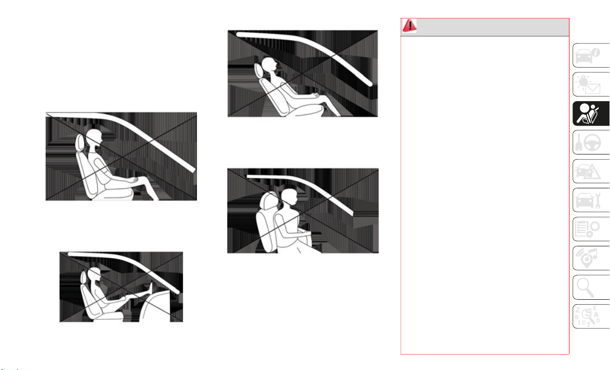
103
The OCS determines the front passenger’s
most probable classification. If an occupant
in the front passenger seat is seated improp
-
erly, the occupant may provide an output
signal to
the OCS that is different from the
occupant’s properly seated weight input, for
example:
Not Seated Properly
Not Seated Properly
Not Seated Properly
Not Seated Properly
WARNING!
If a child restraint system, child, small
teenager or adult in the front passenger
seat is seated improperly, the occupant
may provide an output signal to the OCS
that is different from the occupant’s
properly seated weight input. This may
result in serious injury or death in a colli
-
sion.
Always wear your seat belt and sit prop-
erly, with the seatback in an upright
position,
your back against the seatback,
sitting upright, facing forward, in the
center of the seat, with your feet
comfortably on or near the floor.
Do not carry or hold any objects (e.g.,
backpacks, boxes, etc.) while seated in
the front passenger seat. Holding an
object may provide an output signal to
the OCS that is different than the occu
-
pant’s properly seated weight input,
which may
result in serious injury or
death in a collision.
Placing an object on the floor under the
front passenger seat may prevent the
OCS from working properly, which may
result in serious injury or death in a colli
-
sion. Do not place any objects on the
floor und
er the front passenger seat.

SAFETY
104
The Air Bag Warning Light in the instru-
ment panel will turn on whenever the OCS is
unable to
classify the front passenger seat
status. A malfunction in the OCS may affect
the operation of the air bag system.
If the Air Bag Warning Light does not
come on, or stays on after you start the
vehicle,
or it comes on as you drive, take the
vehicle to an authorized dealer for service
immediately.
The passenger seat assembly contains crit-
ical OCS components that may affect the
Passenger
Advanced Front Air Bag inflation.
In order for the OCS to properly classify the
seated weight of a front seat passenger, the
OCS components must function as designed.
Do not make any modifications to the front
passenger seat components, assembly, or to
the seat cover. If the seat, trim cover, or
cushion needs service for any reason, take
the vehicle to an authorized dealer. Only FCA
US LLC approved seat accessories may be
used.
The following requirements must be strictly
followed:
Do not modify the front passenger seat
assembly or components in any way.
Do not use prior or future model year seat
covers or cushions not designated by FCA
US LLC for the specific model being
repaired. Always use the correct seat cover
and cushion specified for the vehicle.
Do not replace the seat cover or cushion
with an aftermarket seat cover or cushion.
Do not add a secondary seat cover or mat.
At no time should any Supplemental
Restraint System (SRS) component or
SRS related component or fastener be
modified or replaced with any part except
those which are approved by FCA US LLC.
WARNING!
Unapproved modifications or service
procedures to the passenger seat
assembly, its related components, seat
cover or cushion may inadvertently
change the air bag deployment in case of
a frontal collision. This could result in
death or serious injury to the front
passenger if the vehicle is involved in a
collision. A modified vehicle may not
comply with required Federal Motor
Vehicle Safety Standards (FMVSS) and/
or Canadian Motor Vehicle Safety Stan
-
dards (CMVSS).
If it is necessary to modify the air bag
system for persons with disabilities,
contact an authorized dealer.
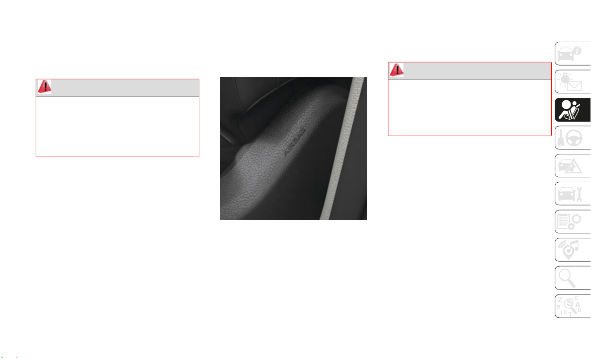
105
Knee Impact Bolsters
The Knee Impact Bolsters help protect the
knees of the driver and front passenger, and
position the front occupants for improved
interaction with the front air bags.
Supplemental Side Air Bags
Supplemental Seat-Mounted Side Air Bags
(SABs)
This vehicle is equipped with Supplemental
Seat-Moun
ted Side Air Bags (SABs).
Supplemental Seat-Mounted Side Air Bags
(SABs) ar
e located in the outboard side of
the front seats. The SABs are marked with
“SRS AIRBAG” or “AIRBAG” on a label or on
the seat trim on the outboard side of the
seats.
The SABs may help to reduce the risk of
occupant
injury during certain side impacts,
in addition to the injury reduction potential
provided by the seat belts and body struc
-
ture.
Supplemental Seat-Mounted Side Air Bag Label
When the SAB deploys, it opens the seam on
t
he outbo
ard side of the seatback’s trim
cover. The inflating SAB deploys through the
seat seam into the space between the occu
-
pant and the door. The SAB moves at a very
high spee
d and with such a high force that it
could injure occupants if they are not seated
properly, or if items are positioned in the
area where the SAB inflates. Children are at
an even greater risk of injury from a
deploying air bag.
Supplemental Side Air Bag Inflatable Curtains
(SABICs)
Th
is vehicle is equipped with Supplemental
Side Air
Bag Inflatable Curtains (SABICs).
Supplemental Side Air Bag Inflatable
Curtains
(SABICs) are located above the side
windows. The trim covering the SABICs is
labeled “SRS AIRBAG” or “AIRBAG.”
WARNING!
Do not drill, cut, or tamper with the knee
impact bolsters in any way.
Do not mount any accessories to the
knee impact bolsters such as alarm
lights, stereos, citizen band radios, etc.
WARNING!
Do not use accessory seat covers or place
objects between you and the Side Air
Bags; the performance could be adversely
affected and/or objects could be pushed
into you, causing serious injury.

SAFETY
106
Supplemental Side Air Bag Inflatable Curtain
(SABIC) Label Location
SABICs may help reduce the risk of head and
other inj
uries to front and rear seat outboard
occupants in certain side impacts, in addi
-
tion to the injury reduction potential
provided
by the seat belts and body struc-
ture.
The SABIC deploys downward, covering the
s
ide wind
ows. An inflating SABIC pushes the
outside edge of the headliner out of the way
and covers the window. The SABICs inflate
with enough force to injure occupants if they
are not belted and seated properly, or if
items are positioned in the area where the
SABICs inflate. Children are at an even
greater risk of injury from a deploying air bag.
The SABICs may help reduce the risk of
partial o
r complete ejection of vehicle occu-
pants through side windows in certain side
i
mpact ev
ents.
Side Impacts
The Side Air Bags are designed to activate in
certain s
ide impacts. The Occupant
Restraint Controller (ORC) determines
whether the deployment of the Side Air Bags
in a particular impact event is appropriate,
based on the severity and type of collision.
The side impact sensors aid the ORC in
determining the appropriate response to
impact events. The system is calibrated to
deploy the Side Air Bags on the impact side
of the vehicle during impacts that require
Side Air Bag occupant protection. In side
impacts, the Side Air Bags deploy inde
-
pendently; a left side impact deploys the left
S
ide Air
Bags only and a right-side impact
deploys the right Side Air Bags only. Vehicle
damage by itself is not a good indicator of
whether or not Side Air Bags should have
deployed.
The Side Air Bags will not deploy in all side
collision
s, including some collisions at
certain angles, or some side collisions that
do not impact the area of the passenger
compartment. The Side Air Bags may deploy
during angled or offset frontal collisions
where the front air bags deploy.
WARNING!
Do not mount equipment, or stack
luggage or other cargo up high enough to
block the deployment of the SABICs.
The trim covering above the side
windows where the SABIC and its
deployment path are located should
remain free from any obstructions.
In order for the SABICs to work as
intended, do not install any accessory
items in your vehicle which could alter
the roof. Do not add an aftermarket
sunroof to your vehicle. Do not add roof
racks that require permanent attach
-
ments (bolts or screws) for installation
o
n the ve
hicle roof. Do not drill into the
roof of the vehicle for any reason.
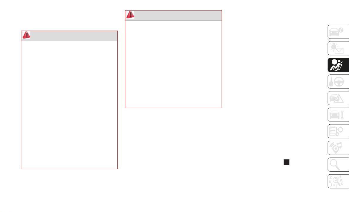
107
Side Air Bags are a supplement to the seat
belt restraint system. Side Air Bags deploy in
less time than it takes to blink your eyes.
NOTE:
Air bag covers may not be obvious in the inte-
rior trim, but they will open during air bag
deploymen
t.
Rollover Events
Side Air Bags are designed to activate in
c
ertain r
ollover events. The ORC determines
whether the deployment of the Side Air Bags
in a particular rollover event is appropriate,
based on the severity and type of collision.
Vehicle damage by itself is not a good indi
-
cator of whether or not Side Air Bags should
h
ave depl
oyed.
The Side Air Bags will not deploy in all roll-
over events. The rollover sensing system
determine
s if a rollover event may be in prog-
ress and whether deployment is appropriate.
I
n the ev
ent the vehicle experiences a roll-
over or near rollover event, and deployment
o
f the Si
de Air Bags is appropriate, the roll-
over sensing system will also deploy the seat
b
elt pret
ensioners on both sides of the
vehicle.
The SABICs may help reduce the risk of
partial o
r complete ejection of vehicle occu-
pants through side windows in certain roll-
over or side impact events.
Air Bag System Components
NOTE:
The Occupant Restraint Controller (ORC)
monitors
the internal circuits and intercon-
necting wiring associated with electrical Air
B
ag Syste
m Components listed below:
Occupant Restraint Controller (ORC)
Air Bag Warning Light
Steering Wheel and Column
Instrument Panel
WARNING!
Occupants, including children, who are
up against or very close to Side Air Bags
can be seriously injured or killed. Occu
-
pants, including children, should never
lean on o
r sleep against the door, side
windows, or area where the side air bags
inflate, even if they are in an infant or
child restraint.
Seat belts (and child restraints where
appropriate) are necessary for your
protection in all collisions. They also
help keep you in position, away from an
inflating Side Air Bag. To get the best
protection from the Side Air Bags, occu
-
pants must wear their seat belts properly
a
nd sit u
pright with their backs against
the seats. Children must be properly
restrained in a child restraint or booster
seat that is appropriate for the size of the
child.
WARNING!
Side Air Bags need room to inflate. Do
not lean against the door or window. Sit
upright in the center of the seat.
Being too close to the Side Air Bags
during deployment could cause you to be
severely injured or killed.
Relying on the Side Air Bags alone could
lead to more severe injuries in a colli-
sion. The Side Air Bags work with your
s
eat belt
to restrain you properly. In
some collisions, Side Air Bags won’t
deploy at all. Always wear your seat belt
even though you have Side Air Bags.

SAFETY
108
Knee Impact Bolsters
Driver and Front Passenger Air Bags
Seat Belt Buckle Switch
Supplemental Side Air Bags
Front and Side Impact Sensors
Seat Belt Pretensioners
Seat Track Position Sensors
Occupant Classification System
If A Deployment Occurs
The front air bags are designed to deflate
immediately after deployment.
NOTE:
Front and/or side air bags will not deploy in
a
ll colli
sions. This does not mean something
is wrong with the air bag system.
If you do have a collision which deploys the
air bags,
any or all of the following may
occur:
The air bag material may sometimes cause
abrasions and/or skin reddening to the
occupants as the air bags deploy and
unfold. The abrasions are similar to fric
-
tion rope burns or those you might get
sliding a
long a carpet or gymnasium floor.
They are not caused by contact with chem-
icals. They are not permanent and
normally
heal quickly. However, if you
haven’t healed significantly within a few
days, or if you have any blistering, see your
doctor immediately.
As the air bags deflate, you may see some
smoke-like particles. The particles are a
normal by-product of the process that
generates the non-toxic gas used for air
bag inflation. These airborne particles may
irritate the skin, eyes, nose, or throat. If
you have skin or eye irritation, rinse the
area with cool water. For nose or throat irri
-
tation, move to fresh air. If the irritation
continues
, see your doctor. If these parti-
cles settle on your clothing, follow the
g
arment m
anufacturer’s instructions for
cleaning.
Do not drive your vehicle after the air bags
have depl
oyed. If you are involved in another
collision, the air bags will not be in place to
protect you.
NOTE:
Air bag covers may not be obvious in the
interior trim, but they will open during air
bag deployment.
After any collision, the vehicle should be
taken to an authorized dealer immedi-
ately.
WARNING!
Deployed air bags and seat belt
pretensioners cannot protect you in
another collision. Have the air bags, seat
belt pretensioners, and the seat belt
retractor assemblies replaced by an
authorized dealer immediately. Also, have
the Occupant Restraint Controller System
serviced as well.

109
(Continued)
Enhanced Accident Response System
In the event of an impact, if the communica-
tion network remains intact, and the power
remains in
tact, depending on the nature of the
event, the ORC will determine whether to have
the Enhanced Accident Response System
perform the following functions:
Cut off fuel to the engine (If Equipped)
Cut off battery power to the electric motor (If
Equipped)
Flash hazard lights as long as the battery has
power
Turn on the interior lights, which remain on
as long as the battery has power or for
15
minutes from the intervention of the
Enhanced A
ccident Response System.
Unlock the power door locks.
Your vehicle may also be designed to perform
any of the
se other functions in response to the
Enhanced Accident Response System:
Turn off the Fuel Filter Heater, Turn off the
HVAC Blower Motor, Close the HVAC Circu-
lation Door
Cut off battery power to the:
Engine
Electric Motor (if equipped)
Electric power steering
Brake booster
Electric park brake
Automatic transmission gear selector
Horn
Front wiper
Headlamp washer pump
NOTE:
After an accident, remember to cycle the
i
gnition t
o the STOP (OFF/LOCK) position
and remove the key from the ignition switch
to avoid draining the battery. Carefully check
the vehicle for fuel leaks in the engine
compartment and on the ground near the
engine compartment and fuel tank before
resetting the system and starting the engine.
If there are no fuel leaks or damage to the
vehicle electrical devices (e.g. headlights)
after an accident, reset the system by
following the procedure described below. If
you have any doubt, contact an authorized
dealer.
Enhanced Accident Response System Reset
Procedure
In order to reset the Enhanced Accident
Response System functions after an event,
the ignition switch must be changed from
ignition START or ON/RUN to ignition OFF.
Carefully check the vehicle for fuel leaks in
the engine compartment and on the ground
near the engine compartment and fuel tank
before resetting the system and starting the
engine.
Maintaining Your Air Bag System
WARNING!
Modifications to any part of the air bag
system could cause it to fail when you
need it. You could be injured if the air
bag system is not there to protect you.
Do not modify the components or wiring,
including adding any kind of badges or
stickers to the steering wheel hub trim
cover or the upper passenger side of the
instrument panel. Do not modify the
front bumper, vehicle body structure, or
add aftermarket side steps or running
boards.
It is dangerous to try to repair any part of
the air bag system yourself. Be sure to
tell anyone who works on your vehicle
that it has an air bag system.

SAFETY
110
Event Data Recorder (EDR)
This vehicle is equipped with an event data
recorder (EDR). The main purpose of an EDR
is to record, in certain crash or near
crash-like situations, such as an air bag
deployment or hitting a road obstacle, data
that will assist in understanding how a
vehicle’s systems performed. The EDR is
designed to record data related to vehicle
dynamics and safety systems for a short
period of time, typically 30 seconds or less.
The EDR in this vehicle is designed to record
such data as:
How various systems in your vehicle were
operating;
Whether or not the driver and passenger
safety belts were buckled/fastened;
How far (if at all) the driver was depressing
the accelerator and/or brake pedal; and,
How fast the vehicle was traveling.
These data can help provide a better under-
standing of the circumstances in which
crashes a
nd injuries occur.
NOTE:
EDR data are recorded by your vehicle only if
a
non-tri
vial crash situation occurs; no data
are recorded by the EDR under normal
driving conditions and no personal data (e.g.,
name, gender, age, and crash location) are
recorded. However, other parties, such as
law enforcement, could combine the EDR
data with the type of personally identifying
data routinely acquired during a crash inves
-
tigation.
To read data recorded by an EDR, special
e
quipment
is required, and access to the
vehicle or the EDR is needed. In addition to
the vehicle manufacturer, other parties, such
as law enforcement, that have the special
equipment, can read the information if they
have access to the vehicle or the EDR.
Child Restraints
Everyone in your vehicle needs to be buckled
up at all times, including babies and chil-
dren. Every state in the United States, and
e
very Can
adian province, requires that small
children ride in proper restraint systems.
This is the law, and you can be prosecuted
for ignoring it.
Children 12 years or younger should ride
properly
buckled up in a rear seat, if avail-
able. According to crash statistics, children
a
re safer
when properly restrained in the rear
seats rather than in the front.
Do not attempt to modify any part of your
air bag system. The air bag may inflate
accidentally or may not function properly
if modifications are made. Take your
vehicle to an authorized dealer for any air
bag system service. If your seat,
including your trim cover and cushion,
needs to be serviced in any way
(including removal or loosening/tight
-
ening of seat attachment bolts), take the
v
ehicle t
o an authorized dealer. Only
manufacturer approved seat accessories
may be used. If it is necessary to modify
the air bag system for persons with
disabilities, contact an authorized
dealer.
WARNING! (Continued)
WARNING!
In a collision, an unrestrained child can
become a projectile inside the vehicle. The
force required to hold even an infant on
your lap could become so great that you
could not hold the child, no matter how
strong you are. The child and others could
be badly injured or killed. Any child riding
in your vehicle should be in a proper
restraint for the child’s size.

111
There are different sizes and types of
restraints for children from newborn size to
the child almost large enough for an adult
safety belt. Always check the child seat
Owner’s Manual to make sure you have the
correct seat for your child. Carefully read and
follow all the instructions and warnings in
the child restraint Owner’s Manual and on all
the labels attached to the child restraint.
Before buying any restraint system, make
sure that it has a label certifying that it
meets all applicable Safety Standards. You
should also make sure that you can install it
in the vehicle where you will use it.
NOTE:
For additional information, refer to http://
www.nhtsa.gov/parents-and-caregivers or
call: 1
–888–327–4236
Canadian residents should refer to Trans-
port Canada’s website for additional infor-
mation: http://www.tc.gc.ca/eng/
motorvehiclesafety/safedrivers-child-
safety-index-53.htm
Summary Of Recommendations For Restraining Children In Vehicles
Child Size, Height, Weight Or Age Recommended Type Of Child Restraint
Infants and Toddlers Children who are two years old or younger
and who have not reached the height or
weight limits of their child restraint
Either an Infant Carrier or a Convertible Child
Restraint, facing rearward in a rear seat of
the vehicle
Small Children Children who are at least two years old or
who have
outgrown the height or weight limit
of their rear-facing child restraint
Forward-Facing Child Restraint with a
five-point Harness, facing forward in a rear
seat of the vehicle
Larger Children Children who have outgrown their
forward-f
acing child restraint, but are too
small to properly fit the vehicle’s seat belt
Belt Positioning Booster Seat and the vehicle
seat belt, seated in a rear seat of the vehicle
Children Too Large for Child Restraints Children 12 years old or younger, who have
outgrown
the height or weight limit of their
booster seat
Vehicle Seat Belt, seated in a rear seat of the
vehicle

SAFETY
112
Infant And Child Restraints
Safety experts recommend that children ride
rear-facing in the vehicle until they are two
years old or until they reach either the height
or weight limit of their rear-facing child
restraint. Two types of child restraints can be
used rear-facing: infant carriers and convert
-
ible child seats.
The infant carrier is only used rear-facing in
t
he vehic
le. It is recommended for children
from birth until they reach the weight or
height limit of the infant carrier. Convertible
child seats can be used either rear-facing or
forward-facing in the vehicle. Convertible
child seats often have a higher weight limit
in the rear-facing direction than infant
carriers do, so they can be used rear-facing
by children who have outgrown their infant
carrier but are still less than at least two
years old. Children should remain rear-facing
until they reach the highest weight or height
allowed by their convertible child seat.
Older Children And Child Restraints
Children who are two years old or who have
outgrown their rear-facing convertible child
seat can ride forward-facing in the vehicle.
Forward-facing child seats and convertible
child seats used in the forward-facing direc
-
tion are for children who are over two years
old or wh
o have outgrown the rear-facing
weight or height limit of their rear-facing
convertible child seat. Children should
remain in a forward-facing child seat with a
harness for as long as possible, up to the
highest weight or height allowed by the child
seat.
All children whose weight or height is above
the forwa
rd-facing limit for the child seat
should use a belt-positioning booster seat
until the vehicle’s seat belts fit properly. If
the child cannot sit with knees bent over the
vehicle’s seat cushion while the child’s back
is against the seatback, they should use a
belt-positioning booster seat. The child and
belt-positioning booster seat are held in the
vehicle by the seat belt.
WARNING!
Never place a rear-facing child restraint
in front of an air bag. A deploying
passenger front air bag can cause death
or serious injury to a child 12 years or
younger, including a child in a
rear-facing child restraint.
Never install a rear-facing child restraint
in the front seat of a vehicle. Only use a
rear-facing child restraint in the rear
seat. If the vehicle does not have a rear
seat, do not transport a rear-facing child
restraint in that vehicle.
WARNING!
Do not install a rear-facing car seat using a
rear support leg in this vehicle. The floor
of this vehicle is not designed to manage
the crash forces of this type of car seat. In
a crash, the support leg may not function
as it was designed by the car seat
manufacturer, and your child may be more
severely injured as a result.
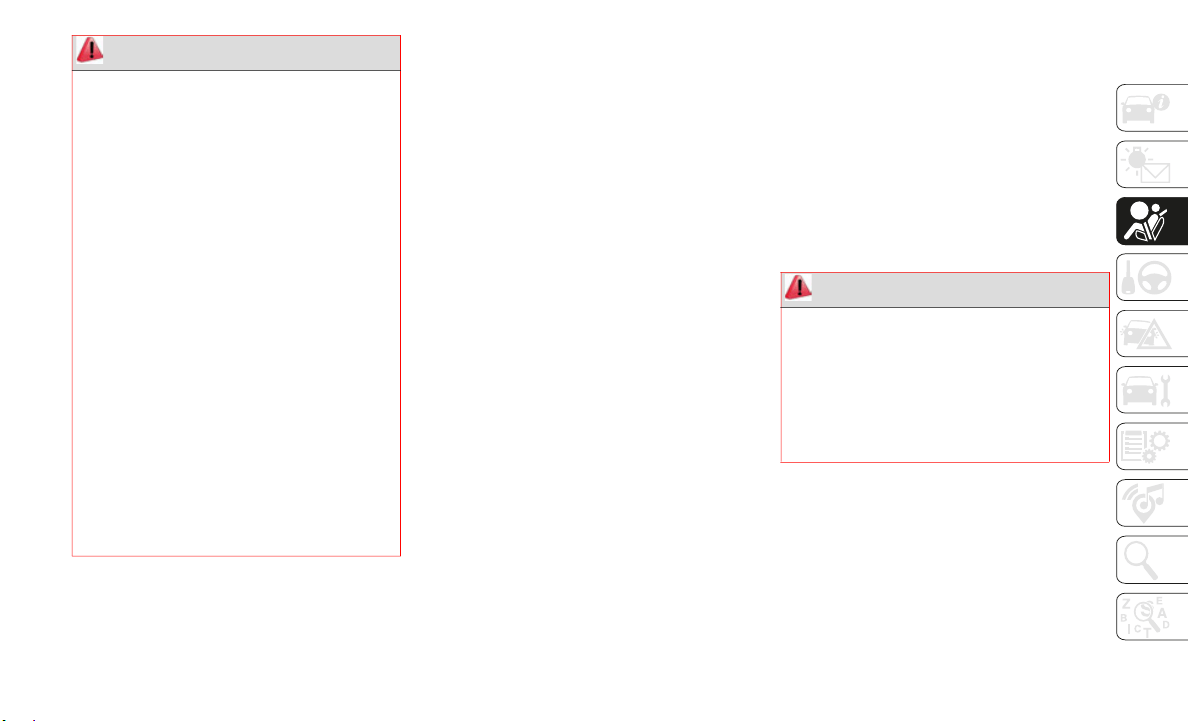
113
Children Too Large For Booster Seats
Children who are large enough to wear the
shoulder belt comfortably, and whose legs
are long enough to bend over the front of the
seat when their back is against the seatback,
should use the seat belt in a rear seat. Use
this simple 5-step test to decide whether the
child can use the vehicle’s seat belt alone:
1. Can the child sit all the way back against
the back
of the vehicle seat?
2. Do the child’s knees bend comfortably
over the
front of the vehicle seat – while
the child is still sitting all the way back?
3. Does the shoulder belt cross the child’s
shoulder
between the neck and arm?
4. Is the lap part of the belt as low as
possible
, touching the child’s thighs and
not the stomach?
5. Can the child stay seated like this for the
whole tr
ip?
If the answer to any of these questions was
“no,” the
n the child still needs to use a
booster seat in this vehicle. If the child is
using the lap/shoulder belt, check seat belt
fit periodically and make sure the seat belt
buckle is latched. A child’s squirming or
slouching can move the belt out of position.
If the shoulder belt contacts the face or
neck, move the child closer to the center of
the vehicle, or use a booster seat to position
the seat belt on the child correctly.
WARNING!
Improper installation can lead to failure
of an infant or child restraint. It could
come loose in a collision. The child
could be badly injured or killed. Follow
the child restraint manufacturer’s direc
-
tions exactly when installing an infant or
child res
traint.
After a child restraint is installed in the
vehicle, do not move the vehicle seat
forward or rearward because it can
loosen the child restraint attachments.
Remove the child restraint before
adjusting the vehicle seat position.
When the vehicle seat has been
adjusted, reinstall the child restraint.
When your child restraint is not in use,
secure it in the vehicle with the seat belt
or LATCH anchorages, or remove it from
the vehicle. Do not leave it loose in the
vehicle. In a sudden stop or accident, it
could strike the occupants or seatbacks
and cause serious personal injury.
WARNING!
Never allow a child to put the shoulder
belt under an arm or behind their back. In
a crash, the shoulder belt will not protect a
child properly, which may result in serious
injury or death. A child must always wear
both the lap and shoulder portions of the
seat belt correctly.

SAFETY
114
Recommendations For Attaching Child Restraints
Lower Anchors And Tethers For CHildren
(LATCH) R
estraint System
LATCH Label
Your vehicle is equipped with the child
restraint
anchorage system called LATCH,
which stands for Lower Anchors and Tethers
for CHildren. The LATCH system has three
vehicle anchor points for installing
LATCH-equipped child seats. There are two
lower anchorages located at the back of the
seat cushion where it meets the seatback
and one top tether anchorage located behind
the seating position. These anchorages are
used to install LATCH-equipped child seats
without using the vehicle’s seat belts. Some
seating positions may have a top tether
anchorage but no lower anchorages. In these
seating positions, the seat belt must be used
with the top tether anchorage to install the
child restraint. Please see the following table
for more information.
Restraint Type
Combined Weight of
the Child + Child
Res
traint
Use Any Attachment Method Shown With An “X” Below
LATCH – Lower
Anchors Only
Sea
t Belt Only
LATCH – Lower
An
chors +
Top Tether
Anchor
Seat Belt + Top
Tether Ancho
r
Rear-Facing Child
Restraint
Up to 65 lbs
(29.5 kg)
X X
Rear-Facing Child
Restraint
M
ore than 65 lbs
(29.5 kg)
X
Forward-Facing Child
Restraint
U
p to 65 lbs
(29.5 kg)
X X
Forward-Facing Child
Restraint
M
ore than 65 lbs
(29.5 kg)
X
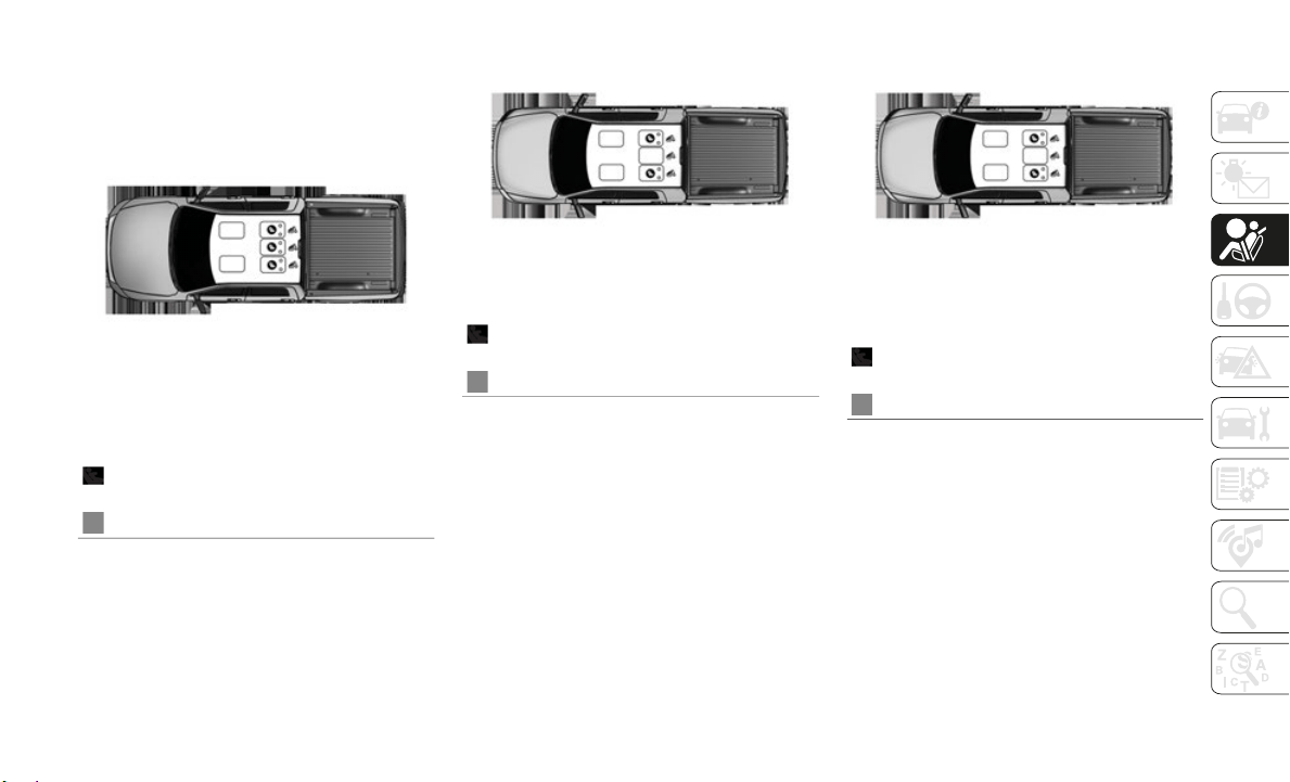
115
LATCH Positions For Installing Child
Restraints In This Vehicle
Crew Cab 60/40 Split Bench LATCH Positions
Crew Cab Full Bench LATCH Positions Quad Cab Full Bench And 60/40 Split Bench
LATCH Positions
Lower Anchorage Symbol (2 Anchorages
Per Seating Position)
Top Tether Anchorage Symbol
Lower Anchorage Symbol (2 Anchorages
Per Seating Position)
Top Tether Anchorage Symbol
Lower Anchorage Symbol (2 Anchorages
Per Seating Position)
Top Tether Anchorage Symbol

SAFETY
116
Frequently Asked Questions About Installing Child Restraints With LATCH
What is the weight limit (child’s weight +
weight of the child restraint) for using the
LATCH anchorage system to attach the child
restraint?
65 lbs (29.5 kg) Use the LATCH anchorage system until the
combined weight of the child and the child
restraint is 65 lbs (29.5 kg). Use the seat
belt and tether anchor instead of the LATCH
system once the combined weight is more
than 65 lbs (29.5 kg).
Can the LATCH anchorages and the seat belt
be used t
ogether to attach a rear-facing or
forward-facing child restraint?
No Do not use the seat belt when you use the
LATCH anchorage system to attach a
rear-facing or forward-facing child restraint.
Booster seats may be attached to the LATCH
anchorage
s if allowed by the booster seat
manufacturer. See your booster seat owner’s
manual for more information.
Can a child seat be installed in the center
position
using the inner LATCH lower
anchorages?
No Quad Cab or Crew with Full bench rear seat:
Use the seat belt and tether anchor to install
a child seat in the center seating position
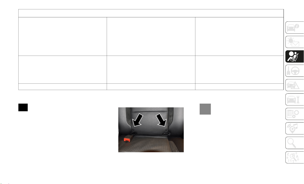
117
Locating The LATCH Anchorages
The lower anchorages are round bars
that are found at the rear of the seat
cushion w
here it meets the seatback, below
the anchorage symbols on the seatback.
They are just visible when you lean into the
rear seat to install the child restraint. You
will easily feel them if you run your finger
along the gap between the seatback and seat
cushion.
Rear Outboard Seats Driver Side (Example
Shown)
Locating The Upper Tether Anchorages
There are tether strap anchorages
located behind each of the rear seats.
Can two child restraints be attached using a
common lo
wer LATCH anchorage?
No Never “share” a LATCH anchorage with two
or more child restraints. If the center
position does not have dedicated LATCH
lower anchorages, use the seat belt to install
a child seat in the center position next to a
child seat using the LATCH anchorages in an
outboard position.
Can the rear-facing child restraint touch the
back of t
he front passenger seat?
Yes The child seat may touch the back of the
front passenger seat if the child restraint
manufacturer also allows contact. See your
child restraint owner’s manual for more
information.
Can the rear head restraints be removed? No
Frequently Asked Questions About Installing Child Restraints With LATCH

SAFETY
118
(Continued)
Outboard Tether Anchorage
Center Tether Anchorage Over Head Rest
LATCH-compatible child restraint systems
will be e
quipped with a rigid bar or a flexible
strap on each side. Each will have a hook or
connector to attach to the lower anchorage
and a way to tighten the connection to the
anchorage. Forward-facing child restraints
and some rear-facing child restraints will
also be equipped with a tether strap. The
tether strap will have a hook at the end to
attach to the top tether anchorage and a way
to tighten the strap after it is attached to the
anchorage.
Center Seat LATCH
All Quad Cabs Or Crew Cab Full Bench Rear
Seat: No Lower Center LATCH Anchorages
Available
Crew Cab Split Bench Rear Seat: Center Lower
LATCH Anc
horages Available
If a child restraint installed in the center posi-
tion blocks the seat belt webbing or buckle for
the outbo
ard position, do not use that outboard
position. If a child seat in the center position
blocks the outboard LATCH anchors or seat
belt, do not install a child seat in that outboard
position.
Always follow the directions of the child restraint
manufactu
rer when installing your child restraint.
Not all child restraint systems will be installed as
described here.
WARNING!
Do not install a child restraint in the
center position using the LATCH system.
This position is not approved for
installing child seats using the LATCH
attachments. You must use the seat belt
and tether anchor to install a child seat
in the center seating position.
Never use the same lower anchorage to
attach more than one child restraint.
Please refer to “To Install A
LATCH-Compatible Child Restraint” for
typical installation instructions.
WARNING!
Never use the same lower anchorage to
attach more than one child restraint.
Please refer to “To Install A
LATCH-Compatible Child Restraint” for
typical installation instructions.
WARNING! (Continued)

119
To Install A LATCH-Compatible Child
Restraint
If the selected seating position has a Switch-
able Automatic Locking Retractor (ALR) seat
belt, sto
w the seat belt, following the instruc-
tions below. See the section “Installing Child
R
estraint
s Using the Vehicle Seat Belt” to
check what type of seat belt each seating
position has.
1. Loosen the adjusters on the lower straps
and on t
he tether strap of the child seat
so that you can more easily attach the
hooks or connectors to the vehicle
anchorages.
2. Place the child seat between the lower
anchorag
es for that seating position. For
some second row seats, you may need to
recline the seat and / or raise the head
restraint (if adjustable) to get a better fit.
If the rear seat can be moved forward and
rearward in the vehicle, you may wish to
move it to its rear-most position to make
room for the child seat. You may also
move the front seat forward to allow more
room for the child seat.
3. Attach the lower hooks or connectors of
the chil
d restraint to the lower anchor-
ages in the selected seating position.
4. If the child restraint has a tether strap,
connect
it to the top tether anchorage.
See the section “Installing Child
Restraints Using the Top Tether
Anchorage” for directions to attach a
tether anchor.
5. Tighten all of the straps as you push the
child re
straint rearward and downward
into the seat. Remove slack in the straps
according to the child restraint manufac
-
turer’s instructions.
6. T
est that the child restraint is installed
tightly
by pulling back and forth on the
child seat at the belt path. It should not
move more than 1
inch (25.4 mm) in any
direction
.
How To Stow An Unused Switchable-ALR
(ALR) Seat Belt:
When using the LATCH attaching system to
install a child restraint, stow all ALR seat
belts that are not being used by other occu
-
pants or being used to secure child
restraint
s. An unused belt could injure a
child if they play with it and accidentally lock
the seat belt retractor. Before installing a
child restraint using the LATCH system,
buckle the seat belt behind the child
restraint and out of the child’s reach. If the
buckled seat belt interferes with the child
restraint installation, instead of buckling it
behind the child restraint, route the seat belt
through the child restraint belt path and then
buckle it. Do not lock the seat belt. Remind
all children in the vehicle that the seat belts
are not toys and that they should not play
with them.
WARNING!
Improper installation of a child restraint
to the LATCH anchorages can lead to
failure of the restraint. The child could
be badly injured or killed. Follow the
child restraint manufacturer’s directions
exactly when installing an infant or child
restraint.
Child restraint anchorages are designed
to withstand only those loads imposed by
correctly-fitted child restraints. Under
no circumstances are they to be used for
adult seat belts, harnesses, or for
attaching other items or equipment to
the vehicle.
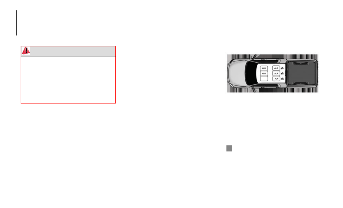
SAFETY
120
Installing Child Restraints Using The Vehicle
Seat Belt
Child restraint systems are designed to be
secured in vehicle seats by lap belts or the
lap belt portion of a lap/shoulder belt.
The seat belts in the passenger seating posi-
tions are equipped with a Switchable Auto-
matic Locking Retractor (ALR) that is
designed
to keep the lap portion of the seat
belt tight around the child restraint so that it
is not necessary to use a locking clip. The
ALR retractor can be “switched” into a
locked mode by pulling all of the webbing
out of the retractor and then letting the
webbing retract back into the retractor. If it
is locked, the ALR will make a clicking noise
while the webbing is pulled back into the
retractor.
Refer to the “Automatic Locking Mode”
descripti
on in “Switchable Automatic
Locking Retractors (ALR)” under “Occupant
Restraint Systems” for additional informa
-
tion on ALR.
Please see the table below and the following
sections
for more information.
Lap/Shoulder Belt Systems For Installing
Child Restraints In This Vehicle
Automatic Locking Retractor (ALR) Locations
WARNING!
Improper installation or failure to prop-
erly secure a child restraint can lead to
failure o
f the restraint. The child could
be badly injured or killed.
Follow the child restraint manufacturer’s
directions exactly when installing an
infant or child restraint.
ALR = Switchable Automatic Locking Re-
tractor
Top Tether Anchorage Symbol
121
Installing A Child Restraint With A Switchable
Automatic Locking Retractor (ALR):
Child restraint systems are designed to be
secured in vehicle seats by lap belts or the
lap belt portion of a lap/shoulder belt.
1. Place the child seat in the center of the
seating
position. For some second row
seats, you may need to recline the seat
and/or raise the head restraint (if adjust
-
able) to get a better fit. If the rear seat
can be mo
ved forward and rearward in
the vehicle, you may wish to move it to its
rear-most position to make room for the
child seat. You may also move the front
seat forward to allow more room for the
child seat.
2. Pull enough of the seat belt webbing
from the
retractor to pass it through the
belt path of the child restraint. Do not
twist the belt webbing in the belt path.
3. Slide the latch plate into the buckle until
you hear
a “click.”
4. Pull on the webbing to make the lap
portion
tight against the child seat.
5. To lock the seat belt, pull down on the
shoulder
part of the belt until you have
pulled all the seat belt webbing out of the
retractor. Then, allow the webbing to
retract back into the retractor. As the
webbing retracts, you will hear a clicking
sound. This means the seat belt is now in
the Automatic Locking mode.
Frequently Asked Questions About Installing Child Restraints With Seat Belts
What is the weight limit (child’s weight +
weight of the child restraint) for using the
Tether Anchor with the seat belt to attach a
forward facing child restraint?
Weight limit of the Child Restraint Always use the tether anchor when using the
seat belt to install a forward facing child
restraint, up to the recommended weight limit
of the child restraint.
Can the rear-facing child restraint touch the
back of t
he front passenger seat?
Yes Contact between the front passenger seat and
the child restraint is allowed, if the child
restraint manufacturer also allows contact.
Can the rear head restraints be removed? No Head restraints may not be removed.
Can the buckle stalk be twisted to tighten the
seat belt
against the belt path of the child
restraint?
No Do not twist the buckle stalk in a seating
position with an ALR retractor.
WARNING!
Improper installation or failure to prop-
erly secure a child restraint can lead to
failure o
f the restraint. The child could
be badly injured or killed.
Follow the child restraint manufacturer’s
directions exactly when installing an
infant or child restraint.
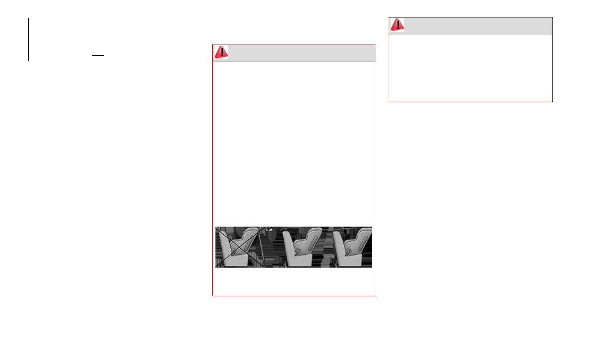
SAFETY
122
6. Try to pull the webbing out of the
retractor. If it is locked, you should not
be able to pull out any webbing. If the
retractor is
not
locked, repeat step 5.
7. Finally, pull up on any excess webbing to
tighten the lap portion around the child
restraint while you push the child
restraint rearward and downward into the
vehicle seat.
8. If the child restraint has a top tether
strap an
d the seating position has a top
tether anchorage, connect the tether
strap to the anchorage and tighten the
tether strap. See the section “Installing
Child Restraints Using the Top Tether
Anchorage” for directions to attach a
tether anchor.
9. Test that the child restraint is installed
tightly
by pulling back and forth on the
child seat at the belt path. It should not
move more than 1
inch (25.4 mm) in any
direction
.
Any seat belt system will loosen with time, so
check the
belt occasionally, and pull it tight
if necessary.
Installing Child Restraints Using The Top
Tether Anchorage
The top tether anchorages in this vehicle are
tether strap loops located between the rear
glass and the back of the rear seat. There is
a tether strap loop located behind each
seating position. Follow the steps below to
attach the tether strap of the child restraint.
Right Or Left Outboard Seats:
1. Reach between the rear seat and rear
glass to
access the tether strap loop.
2. Place a child restraint on the seat and
adjust t
he tether strap so that it will
reach over the seat back, through the
space between the head restraint and the
seat back, through the tether strap loop
behind the seat and over to the tether
strap loop behind the center seat.
WARNING!
Do not attach a tether strap for a
rear-facing car seat to any location in front
of the car seat, including the seat frame or
a tether anchorage. Only attach the tether
strap of a rear-facing car seat to the tether
anchorage that is approved for that seating
position, located behind the top of the
vehicle seat. See the section “Lower
Anchors and Tethers for CHildren (LATCH)
Restraint System” for the location of
approved tether anchorages in your
vehicle.
WARNING!
Never place a rear-facing child restraint in
front of an air bag. A deploying Passenger
Front Air Bag can cause death or serious
injury to a child 12 years or younger,
including a child in a rear-facing child
restraint.

123
3. Pass the tether strap hook through the
space between the head restraint and the
seat back behind the child seat, through
the tether strap loop behind the seat and
over to the center tether strap loop.
Tether Strap Through Outboard Tether Strap
Loop
4. Attach the hook to the center tether strap
loop (se
e diagram). Tighten the tether
strap according to the child seat manu
-
facturer’s instructions.
Tether Strap Through Outboard Tether Strap
Loop And Attached To Center Tether Strap Loop
NOTE:
If there are child seats in both of the
outboard
(left and right) seating positions,
the tether strap hooks of both child seats
should be connected to the center tether
strap loop. This is the correct way to tether
two outboard child seats.
Center Seat:
1. R
each between the rear seat and rear
glass to
access the tether strap loop.
Center Tether Strap Loop Location
2. Place a child restraint on the seat and
adjust t
he tether strap so that it will
reach over the seat back and headrest,
through the tether strap loop behind the
seat and over to the tether strap loop
behind either the right or left outboard
seat.
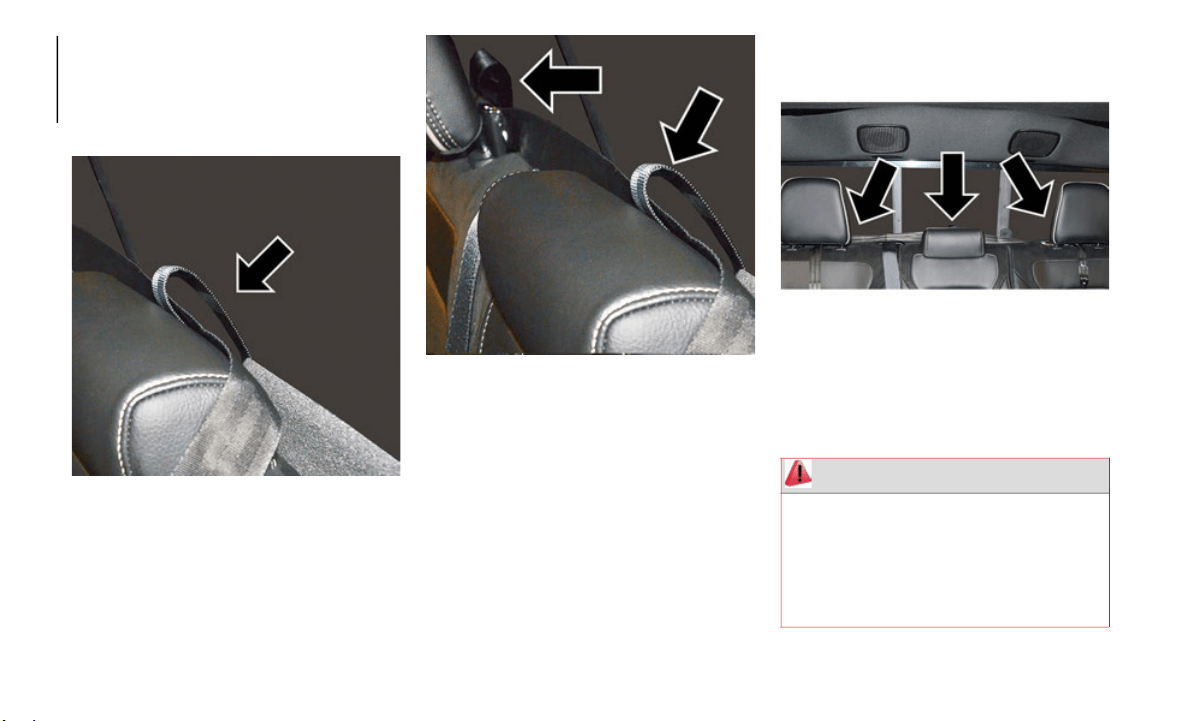
SAFETY
124
(Continued)
3. Pass the tether strap hook over the head-
rest behind the child seat, through the
tether st
rap loop behind the seat and over
to the right or left outboard tether strap
loop.
Tether Strap Through Center Tether Strap Loop
4. Attach the hook to the outboard tether
strap lo
op (see diagram). Tighten the
tether strap according to the child seat
manufacturer’s instructions.
Tether Strap Through Center Tether Strap Loop
And Attached To Outboard Tether Strap Loop
Installing Three Child Restraints:
1. Place a child restraint on each outboard
rear sea
t. Route the tether straps following
the directions for right and left seating
positions, above.
2. Attach both hooks to the center tether strap
loop, bu
t do not tighten the straps yet.
3. Place a child restraint on the center rear
seat. Ro
ute the tether strap following the
directions for the center seating position,
above.
4. Attach the hook to the outboard tether strap
loop.
Outb
oard And Center Seating Positions Shown
5. T
ighten the tether straps according to the
child se
at manufacturer’s instructions,
tightening the right and left tether straps
before the center tether strap.
WARNING!
An incorrectly anchored tether strap
could lead to increased head motion and
possible injury to the child. Use only the
anchorage position directly behind the
child seat to secure a child restraint top
tether strap.
125
(Continued)
Transporting Pets
Air Bags deploying in the front seat could
harm your pet. An unrestrained pet will be
thrown about and possibly injured, or injure
a passenger during panic braking or in a
collision.
Pets should be restrained in the rear seat (if
equipped)
in pet harnesses or pet carriers
that are secured by seat belts.
SAFETY TIPS
Transporting Passengers
NEVER TRANSPORT PASSENGERS IN THE
CARGO AREA.
Exhaust Gas
The best protection against carbon monoxide
entry into the vehicle body is a properly
maintained engine exhaust system.
Whenever a change is noticed in the sound of
the exhaus
t system, when exhaust fumes can
be detected inside the vehicle, or when the
underside or rear of the vehicle is damaged,
have a competent mechanic inspect the
complete exhaust system and adjacent body
areas for broken, damaged, deteriorated, or
mispositioned parts. Open seams or loose
If your vehicle is equipped with a split
rear seat, make sure the tether strap
does not slip into the opening between
the seatbacks as you remove slack in the
strap.
WARNING! (Continued)
WARNING!
Do not leave children or animals inside
parked vehicles in hot weather. Interior
heat build-up may cause serious injury or
death.
It is extremely dangerous to ride in a
cargo area, inside or outside of a vehicle.
In a collision, people riding in these
areas are more likely to be seriously
injured or killed.
Do not allow people to ride in any area of
your vehicle that is not equipped with
seats and seat belts.
Be sure everyone in your vehicle is in a
seat and using a seat belt properly.
WARNING!
Exhaust gases can injure or kill. They
contain carbon monoxide (CO), which is
colorless and odorless. Breathing it can
make you unconscious and can eventually
poison you. To avoid breathing (CO), follow
these safety tips:
Do not run the engine in a closed garage
or in confined areas any longer than
needed to move your vehicle in or out of
the area.
If you are required to drive with the
trunk/liftgate/rear doors open, make sure
that all windows are closed and the
climate control BLOWER switch is set at
high speed. DO NOT use the recircula
-
tion mode.
If it is necessary to sit in a parked vehicle
with the engine running, adjust your
heating or cooling controls to force
outside air into the vehicle. Set the
blower at high speed.
WARNING! (Continued)

SAFETY
126
(Continued)
connections could permit exhaust fumes to
seep into the passenger compartment. In
addition, inspect the exhaust system each
time the vehicle is raised for lubrication or oil
change. Replace as required.
Safety Checks You Should Make Inside
The Vehicle
Seat Belts
Inspect the seat belt system periodically,
checking for cuts, frays, and loose parts.
Damaged parts must be replaced immedi
-
ately. Do not disassemble or modify the
system.
Fro
nt seat belt assemblies must be replaced
after a c
ollision. Rear seat belt assemblies
must be replaced after a collision if they
have been damaged (i.e., bent retractor, torn
webbing, etc.). If there is any question
regarding seat belt or retractor condition,
replace the seat belt.
Air Bag Warning Light
The Air Bag warning light will turn on for
four to eight seconds as a bulb check when
the ignit
ion switch is first turned to ON/RUN.
If the light is either not on during starting,
stays on, or turns on while driving, have the
system inspected at an authorized dealer as
soon as possible. After the bulb check, this
light will illuminate with a single chime when
a fault with the Air Bag System has been
detected. It will stay on until the fault is
removed. If the light comes on intermittently
or remains on while driving, have an autho
-
rized dealer service the vehicle immediately.
Refer to “Occupant Restraint Systems” in
“
Safety”
for further information.
Defroster
Check operation by selecting the defrost
mode and place the blower control on high
speed. You should be able to feel the air
directed against the windshield. See an
authorized dealer for service if your defroster
is inoperable.
Floor Mat Safety Information
Always use floor mats designed to fit your
vehicle. Only use a floor mat that does not
interfere with the operation of the acceler
-
ator, brake or clutch pedals. Only use a floor
mat that
is securely attached using the floor
mat fasteners so it cannot slip out of position
and interfere with the accelerator, brake or
clutch pedals or impair safe operation of your
vehicle in other ways.
WARNING!
An improperly attached, damaged, folded,
or stacked floor mat, or damaged floor mat
fasteners may cause your floor mat to
interfere with the accelerator, brake, or
clutch pedals and cause a loss of vehicle
control. To prevent SERIOUS INJURY or
DEATH:
ALWAYS securely attach your floor
mat using the floor mat fasteners. DO
NOT insta
ll your floor mat upside down
or turn your floor mat over. Lightly pull to
confirm mat is secured using the floor
mat fasteners on a regular basis.
ALWAYS REMOVE THE EXISTING
FLOOR MAT FROM THE VEHICLE
before installing any other floor mat.
NEVER install or stack an additional
floor mat on top of an existing floor mat.
ONLY install floor mats designed to fit
your vehicle. NEVER install a floor mat
that cannot be properly attached and
secured to your vehicle. If a floor mat
needs to be replaced, only use a FCA
approved floor mat for the specific make,
model, and year of your vehicle.
127
(Continued)
Periodic Safety Checks You Should Make
Outside The Vehicle
Tires
Examine tires for excessive tread wear and
uneven wear patterns. Check for stones,
nails, glass, or other objects lodged in the
tread or sidewall. Inspect the tread for cuts
and cracks. Inspect sidewalls for cuts,
cracks, and bulges. Check the wheel bolts for
tightness. Check the tires (including spare)
for proper cold inflation pressure.
Lights
Have someone observe the operation of
brake lights and exterior lights while you
work the controls. Check turn signal and high
beam indicator lights on the instrument
panel.
Door Latches
Check for proper closing, latching, and
locking.
Fluid Leaks
Check area under the vehicle after overnight
parking for fuel, coolant, oil, or other fluid
leaks. Also, if gasoline fumes are detected or
if fuel, or brake fluid leaks are suspected.
The cause should be located and corrected
immediately.
ONLY use the driver’s side floor mat on
the driver’s side floor area. To check for
interference, with the vehicle properly
parked with the engine off, fully depress
the accelerator, the brake, and the
clutch pedal (if present) to check for
interference. If your floor mat interferes
with the operation of any pedal, or is not
secure to the floor, remove the floor mat
from the vehicle and place the floor mat
in your trunk.
ONLY use the passenger’s side floor mat
on the passenger’s side floor area.
ALWAYS make sure objects cannot fall
or slide into the driver’s side floor area
when the vehicle is moving. Objects can
become trapped under accelerator,
brake, or clutch pedals and could cause
a loss of vehicle control.
NEVER place any objects under the floor
mat (e.g., towels, keys, etc.). These
objects could change the position of the
floor mat and may cause interference
with the accelerator, brake, or clutch
pedals.
WARNING! (Continued)
If the vehicle carpet has been removed
and re-installed, always properly attach
carpet to the floor and check the floor
mat fasteners are secure to the vehicle
carpet. Fully depress each pedal to
check for interference with the acceler
-
ator, brake, or clutch pedals then
r
e-install
the floor mats.
It is recommended to only use mild soap
and water to clean your floor mats. After
cleaning, always check your floor mat
has been properly installed and is
secured to your vehicle using the floor
mat fasteners by lightly pulling mat.
WARNING! (Continued)

128
(Continued)
STARTING AND OPERATING
STARTING THE ENGINE
Before starting your vehicle, adjust your seat,
adjust both inside and outside mirrors, and
fasten your seat belt.
The starter should not be operated for more
than 10-s
econd intervals. Waiting a few
seconds between such intervals will protect
the starter from overheating.
Normal Starting Using ENGINE START/
STOP Button
To Turn On The Engine Using The ENGINE
START/STOP Button
1. The transmission must be in PARK.
2. Press
and hold the brake pedal while
pushing
the ENGINE START/STOP
button once.
3. The system takes over and attempts to
start th
e vehicle. If the vehicle fails to
start, the starter will disengage automat
-
ically after 10 seconds.
4. If you wish to stop the cranking of the
engine p
rior to the engine starting, push
the button again.
NOTE:
Normal starting of either a cold or a warm
engine is
obtained without pumping or
pressing the accelerator pedal.
To Turn Off The Engine Using ENGINE START/
STOP Butt
on
1. Place the gear selector in PARK, then
push and
release the ENGINE START/
STOP button.
2. The ignition will return to the OFF mode.
3. If the
gear selector is not in PARK, the
ENGINE S
TART/STOP button must be
held for two seconds or three short
pushes in a row with the vehicle speed
above 5 MPH (8
km/h) before the engine
will shut
off. The ignition will remain in
the ACC mode until the gear selector is in
PARK and the button is pushed twice to
the OFF mode.
4. If the gear selector is not in PARK and
the ENGI
NE START/STOP button is
pushed once with the vehicle speed
above 5 MPH (8
km/h), the instrument
cluster w
ill display a “Vehicle Not In Park”
message and the engine will remain
running. Never leave a vehicle out of the
PARK position, or it could roll.
WARNING!
When leaving the vehicle, always make
sure the keyless ignition node is in the
"OFF" mode, remove the key fob from the
vehicle and lock the vehicle.
Never leave children alone in a vehicle, or
with access to an unlocked vehicle.
Allowing children to be in a vehicle unat
-
tended is dangerous for a number of
reasons.
A child or others could be seri-
ously or fatally injured. Children should be
w
arned no
t to touch the parking brake,
brake pedal or the gear selector.
Do not leave the key fob in or near the
vehicle, or in a location accessible to chil-
dren, and do not leave the ignition of a
v
ehicle e
quipped with Keyless Enter-N-Go
in the ACC or ON/RUN mode. A child could
operate power windows, other controls, or
move the vehicle.
Do not leave children or animals inside
parked vehicles in hot weather. Interior
heat build-up may cause serious injury or
death.
WARNING! (Continued)
129
(Continued)
NOTE:
If the gear selector is not in PARK, and the
ENGINE ST
ART/STOP button is pushed once
with the vehicle speed below 5 MPH (8
km/h),
the engin
e will shut off and the ignition will
remain in the ACC position. If vehicle speed
drops below 1.2 MPH (1.9
km/h), the vehicle
may AutoP
ark. See AutoPark section for further
details.
ENGINE START/STOP Button Functions — With
Driver’s
Foot OFF The Brake Pedal (In PARK Or
NEUTRAL Position)
The ENGINE START/STOP button operates
similar t
o an ignition switch. It has three
modes: OFF, ACC, and RUN. To change the
ignition modes without starting the vehicle
and use the accessories, follow these direc
-
tions:
1. S
tart with the ignition in the OFF mode.
2. Push t
he ENGINE START/STOP button
once to
place the ignition to the ACC
mode.
3. Push the ENGINE START/STOP button a
second t
ime to place the ignition to the
RUN mode.
4. Push the ENGINE START/STOP button a
third ti
me to return the ignition to the
OFF mode.
AutoPark — Rotary Shifter and 8-Speed
Transmission Only
AutoPark is a supplemental feature to assist
in placing the vehicle in PARK should the
situations on the following pages occur. It is
a back up system and should not be relied
upon as the primary method by which the
driver shifts the vehicle into PARK.
The conditions under which AutoPark will
engage ar
e outlined on the following pages.
If the vehicle is not in PARK and the driver turns
off the e
ngine, the vehicle may AutoPark.
AutoPark will engage when all of these
condition
s are met:
Vehicle is equipped with a rotary shifter
and an 8-speed transmission
Vehicle is not in PARK
Vehicle Speed is 1.2 MPH (1.9 km/h) or
less
Ignition switched from RUN to ACC
NOTE:
For Keyless Go equipped vehicles, The
engine wi
ll turn off and the ignition switch
will change to ACC mode. After 30
minutes
the ignit
ion switches to OFF automatically,
unless the driver turns the ignition switch
OFF.
WARNING!
Driver inattention could lead to failure to
place the vehicle in PARK. ALWAYS DO
A VISUAL CHECK that your vehicle is in
PARK by verifying that a solid (not
blinking) “P” is indicated in the Instru
-
ment Cluster Display and near the gear
selector.
If the "P" indicator is blinking,
your vehicle is not in PARK. As an added
precaution, always apply the parking
brake when exiting the vehicle.
AutoPark is a supplemental feature. It is
not designed to replace the need to shift
your vehicle into PARK. It is a back up
system and should not be relied upon as
the primary method by which the driver
shifts the vehicle into PARK.
WARNING! (Continued)

STARTING AND OPERATING
130
If the vehicle is not in PARK and the driver exits
the vehicle with the engine running, the vehicle
may AutoPark.
AutoPark will engage when all of these
condition
s are met:
Vehicle is equipped with a rotary shifter
and an 8-speed transmission
Vehicle is not in PARK
Vehicle speed is 1.2 MPH (1.9 km/h) or
less
Driver’s seat belt is unbuckled
Driver’s door is ajar
Brake Pedal is not depressed
The MESSAGE “AutoPark Engaged Shift to P
then Shif
t to Gear” will display in the instru-
ment cluster.
NOTE:
In some cases the ParkSense graphic will be
d
isplayed
in the instrument cluster, causing
the “AutoPark Engaged Shift to P then Shift to
Gear” to not be seen. In these cases, the
shifter must be returned to “P” to select
desired gear.
If the driver shifts into PARK while moving, the
vehicle m
ay AutoPark.
AutoPark will engage ONLYwhen v
ehicle
speed is 1.2 MPH (1.9 km/h) or less.
The MESSAGE “Vehicle Speed is Too High to
Shift to
P”will be displayed in the instrument
cluster if vehicle speed is above 1.2 MPH
(1.9
km/h).
4WD LOW — If Equipped
AutoPark will be disabled when operating the
vehicle i
n 4WD LOW.
The MESSAGE “AutoPark
Disabled” will be
displayed in the instrument cluster.
Additional customer warnings will be given
when all
of these conditions are met:
Vehicle is not in PARK
Driver’s Door is ajar
Vehicle is in 4WD LOW range
The MESSAGE “AutoPark
Not Engaged” will
be displayed in the instrument cluster. A
warning chime will continue until you shift
the vehicle into PARK or the Driver’s Door is
closed.
ALWAYS DO A VISUAL CHECK
that your vehicle
is in PARK by looking for the "P" in the
Instrument Cluster Display and near the
shifter. As an added precaution, always
apply the parking brake when exiting the
vehicle.
ENGINE BLOCK HEATER —
IF EQUIPPED
The engine block heater warms the engine,
and permits quicker starts in cold weather.
Connect the cord to a standard 110-115 Volt
AC electrical outlet with a grounded,
three-wire extension cord.
WARNING!
If vehicle speed is above 1.2 MPH
(1.9 km/h), the transmission will default
to NEUTRA
L until the vehicle speed drops
below 1.2 MPH (1.9
km). A vehicle left in
the NEUTR
AL position can roll. As an
added precaution, always apply the
parking brake when exiting the vehicle.
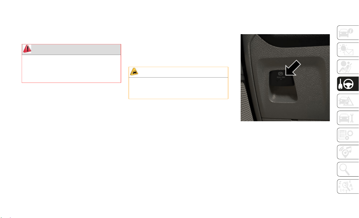
131
The engine block heater cord is routed under
the hood on the passenger side of the vehicle
near the right head lamp assembly. It is
located between the front grill and the radi
-
ator, but underneath the black upper seal.
ENGINE BREAK-IN
RECOMMENDATIONS
A long break-in period is not required for the
engine and drivetrain (transmission and axle)
in your vehicle.
Drive moderately during the first 300 miles
(500 km). A
fter the initial 60 miles
(100 km), s
peeds up to 50 or 55 mph (80 or
90 km/h) ar
e desirable.
While cruising, brief full-throttle accelera-
tion within the limits of local traffic laws
c
ontribute
s to a good break-in. Wide-open
throttle acceleration in low gear can be detri
-
mental and should be avoided.
The engine oil installed in the engine at the
f
actory is
a high-quality energy conserving
type lubricant. Oil changes should be consis
-
tent with anticipated climate conditions
under whic
h vehicle operations will occur.
For the recommended viscosity and quality
grades, re
fer to “Fluids And Lubricants” in
“Technical Specifications”.
NOTE:
A new engine may consume some oil during
its first
few thousand miles (kilometers) of
operation. This should be considered a
normal part of the break-in and not inter
-
preted as a problem.
PARKING BRAKE
Electric Park Brake (EPB)
Your vehicle is equipped with a new Electric
Park Brake System (EPB) that offers greater
convenience. The park brake switch is
located on the instrument panel to the left of
the steering wheel (below the headlamp
switch).
Parking Brake Switch
To apply the park brake manually, pull up on
the switch
momentarily. The BRAKE telltale
light in the instrument cluster and an indi
-
cator on the switch will illuminate.
To release the park brake manually, the igni-
tion must be in ON/RUN. Then put your foot
on the bra
ke pedal and push the park brake
switch down momentarily. Once the park
brake is fully disengaged, the BRAKE telltale
light and the switch indicator will extinguish.
WARNING!
Remember to disconnect the engine block
heater cord before driving. Damage to the
110-115 Volt electrical cord could cause
electrocution.
CAUTION!
Never use Non-Detergent Oil or Straight
Mineral Oil in the engine or damage may
result.

STARTING AND OPERATING
132
(Continued)
(Continued)
The park brake can also be automatically
released. With the engine running and the
transmission in gear, release the brake pedal
and depress the throttle pedal. For safety
reasons, your seat belt must also be
fastened.
NOTE:
You may hear a slight whirring sound from
the back of the vehicle while the parking
brake engages or disengages.
If your foot is on the brake pedal while you
are engaging or disengaging the parking
brake, you may notice a small amount of
brake pedal movement.
The new Auto Park Brake feature can be
used to apply the park brake automatically
every time you park the vehicle. Auto Park
Brake can be enabled and disabled in the
Settings menu in Uconnect.
The parking brake can be engaged even
when the ignition is OFF, however, it can
only be disengaged when the ignition is in
the ON/RUN mode.
SafeHold a new feature that will automat-
ically apply the park brake under certain
condition
s. The EPB monitors the status
of the driver’s seat belt, driver’s door and
pedal positions to determine if the driver
may have exited while the vehicle is still
capable of moving and will then automati
-
cally apply the park brake to prevent the
vehicle f
rom rolling.
The EPB fault light will illuminate if the
EPB switch is held for longer than 90
seconds in either the released or applied
position. The light will extinguish upon
releasing the switch.
Refer to the Starting And Operating
section in the Owner’s Manual for further
information.
WARNING!
Never use the PARK position as a substi-
tute for the parking brake. Always apply
the parki
ng brake fully when exiting the
vehicle to guard against vehicle move
-
ment and possible injury or damage.
When exiting the vehicle, always make
sure the ignition is in the OFF mode,
remove the key fob from the vehicle, and
lock your vehicle.
Never leave children alone in a vehicle,
or with access to an unlocked vehicle.
Allowing children to be in a vehicle unat
-
tended is dangerous for a number of
reasons.
A child or others could be seri-
ously or fatally injured. Children should
b
e warned
not to touch the parking
brake, brake pedal or the transmission
gear selector.
Do not leave the key fob in or near the
vehicle, (or in a location accessible to
children), and do not leave the ignition
in the ACC or ON/RUN mode. A child
could operate power windows, other
controls, or move the vehicle.
Be sure the parking brake is fully disen-
gaged before driving; failure to do so can
lead to b
rake failure and a collision.
Always fully apply the parking brake
when leaving your vehicle, or it may roll
and cause damage or injury. Also be
certain to leave the transmission in
PARK. Failure to do so may allow the
vehicle to roll and cause damage or
injury.
WARNING! (Continued)
133
Auto Park Brake
The electric park brake can be programmed
to be applied automatically whenever the
vehicle is at a standstill and the automatic
transmission is placed in PARK. Auto Park
Brake is enabled and disabled by customer
selection through the customer program
-
mable features section of the Uconnect
S
ettings.
A
ny single auto park brake application can
be bypass
ed by pushing the EPB switch to
the release position while the transmission is
placed in PARK.
SafeHold
SafeHold is a safety feature of the Electric
Park Brake System that will engage the park
brake automatically if the vehicle is left
unsecured while the ignition is in ON/RUN.
For automatic transmissions, the park brake
will auto
matically engage if all of the
following conditions are met:
The vehicle is at a standstill.
There is no attempt to depress the brake
pedal or accelerator pedal.
The seat belt is unbuckled.
The driver door is open.
SafeHold can be temporarily bypassed by
pushing t
he Electric Park Brake Switch while
the driver door is open. Once manually
bypassed, SafeHold will be enabled again
once the vehicle reaches 12
mph (20 km/h)
or the ig
nition is turned to the OFF position
and back to ON again.
Brake Service Mode
We recommend having your brakes serviced
by your authorized dealer. You should only
make repairs for which you have the knowl
-
edge and the right equipment. You should
only ente
r Brake Service Mode during brake
service.
When servicing your rear brakes, it may be
necessary
for you or your technician to push
the rear piston into the rear caliper bore.
With the electric park brake system, this can
only be done after retracting the Electric
Park Brake actuator. Fortunately, actuator
retraction can be done easily by entering the
Brake Service Mode through the Uconnect
Settings in your vehicle. This menu based
system will guide you through the steps
necessary to retract the EPB actuator in
order to perform rear brake service.
Service Mode has requirements that must be
met in or
der to be activated:
The vehicle must be at a standstill.
The park brake must be unapplied.
The transmission must be in PARK or
NEUTRAL.
While in service mode, the Electric Park
Brake fau
lt lamp will flash continuously
while the ignition is ON.
Driving the vehicle with the parking
brake engaged, or repeated use of the
parking brake to slow the vehicle may
cause serious damage to the brake
system.
CAUTION!
If the Brake System Warning Light remains
on with the parking brake released, a
brake system malfunction is indicated.
Have the brake system serviced by an
authorized dealer immediately.
WARNING! (Continued)

STARTING AND OPERATING
134
(Continued)
(Continued)
(Continued)
When brake service work is complete, the
following steps must be followed to reset the
park brake system to normal operation:
Ensure the vehicle is at a standstill.
Press the brake pedal with moderate force.
Apply the Electric Park Brake Switch.
AUTOMATIC
TRANSMISSION
WARNING!
You can be badly injured working on or
around a motor vehicle. Do only that
service work for which you have the
knowledge and the right equipment. If you
have any doubt about your ability to
perform a service job, take your vehicle to
a competent mechanic.
WARNING!
Never use the PARK position as a substi-
tute for the parking brake. Always apply
the parki
ng brake fully when exiting the
vehicle to guard against vehicle move
-
ment and possible injury or damage.
Your vehicle could move and injure you
and others if it is not in PARK. Check by
trying to move the transmission gear
selector out of PARK with the brake
pedal released. Make sure the transmis
-
sion is in PARK before exiting the
vehicle.
The transmission may not engage PARK
if the vehicle is moving. Always bring the
vehicle to a complete stop before
shifting to PARK, and verify that the
transmission gear position indicator
solidly indicates PARK (P) without
blinking. Ensure that the vehicle is
completely stopped, and the PARK posi
-
tion is properly indicated, before exiting
the vehic
le.
It is dangerous to shift out of PARK or
NEUTRAL if the engine speed is higher
than idle speed. If your foot is not firmly
pressing the brake pedal, the vehicle
could accelerate quickly forward or in
reverse. You could lose control of the
vehicle and hit someone or something.
Only shift into gear when the engine is
idling normally and your foot is firmly
pressing the brake pedal.
WARNING! (Continued)
Unintended movement of a vehicle could
injure those in or near the vehicle. As
with all vehicles, you should never exit a
vehicle while the engine is running.
Before exiting a vehicle, always come to
a complete stop, then apply the parking
brake, shift the transmission into PARK,
and turn the ignition OFF. When the igni
-
tion is in the OFF mode, the transmis-
sion is locked in PARK, securing the
v
ehicle a
gainst unwanted movement.
When exiting the vehicle, always make
sure the ignition is in the OFF mode,
remove the key fob from the vehicle, and
lock the vehicle.
Never leave children alone in a vehicle,
or with access to an unlocked vehicle.
Allowing children to be in a vehicle unat
-
tended is dangerous for a number of
reasons.
A child or others could be seri-
ously or fatally injured. Children should
b
e warned
not to touch the parking
brake, brake pedal or the transmission
gear selector.
WARNING! (Continued)
135
NOTE:
You must press and hold the brake pedal
while shi
fting out of PARK.
Ignition Park Interlock
This vehicle is equipped with an Ignition
Park Interlock which requires the transmis-
sion to be in PARK before the ignition can be
t
urned to
the OFF mode. This helps the
driver avoid inadvertently leaving the vehicle
without placing the transmission in PARK.
This system also locks the transmission in
PARK whenever the ignition is in the OFF
mode.
NOTE:
The transmission is NOT locked in PARK
w
hen the
ignition is in the ACC mode (even
though the engine will be off). Ensure that
the transmission is in PARK, and the ignition
is OFF (not in ACC mode) before exiting the
vehicle.
Brake/Transmission Shift Interlock
System
This vehicle is equipped with a Brake Trans-
mission Shift Interlock System (BTSI) that
holds the
transmission gear selector in PARK
unless the brakes are applied. To shift the
transmission out of PARK, the engine must
be running and the brake pedal must be
pressed.
The brake pedal must also be pressed to shift
from NEUT
RAL into DRIVE or REVERSE
when the vehicle is stopped or moving at low
speeds.
Eight-Speed Automatic Transmission
The transmission is controlled using a rotary
electronic gear selector located on the
instrument panel. The transmission gear
range (PRND) is displayed both above the
gear selector and in the instrument cluster.
To select a gear range, simply rotate the gear
selector. You must press the brake pedal to
shift the transmission out of PARK (or
NEUTRAL, when the vehicle is stopped or
moving at low speeds). To shift past multiple
gear ranges at once (such as PARK to
DRIVE), simply rotate the gear selector to the
appropriate detent. Select the DRIVE range
for normal driving.
NOTE:
In the event of a mismatch between the gear
selector
position and the actual transmission
gear (for example, driver selects PARK while
driving), the position indicator will blink
continuously until the selector is returned to
the proper position, or the requested shift
can be completed.
The electronically-controlled transmission
adapts it
s shift schedule based on driver
inputs, along with environmental and road
conditions. The transmission electronics are
self-calibrating; therefore, the first few shifts
on a new vehicle may be somewhat abrupt.
Do not leave the key fob in or near the
vehicle (or in a location accessible to
children), and do not leave the ignition
in the ACC or ON/RUN mode. A child
could operate power windows, other
controls, or move the vehicle.
CAUTION!
Shift into or out of PARK or REVERSE
only after the vehicle has come to a
complete stop.
Do not shift between PARK, REVERSE,
NEUTRAL, or DRIVE when the engine is
above idle speed.
Before shifting into any gear, make sure
your foot is firmly pressing the brake
pedal.
WARNING! (Continued)
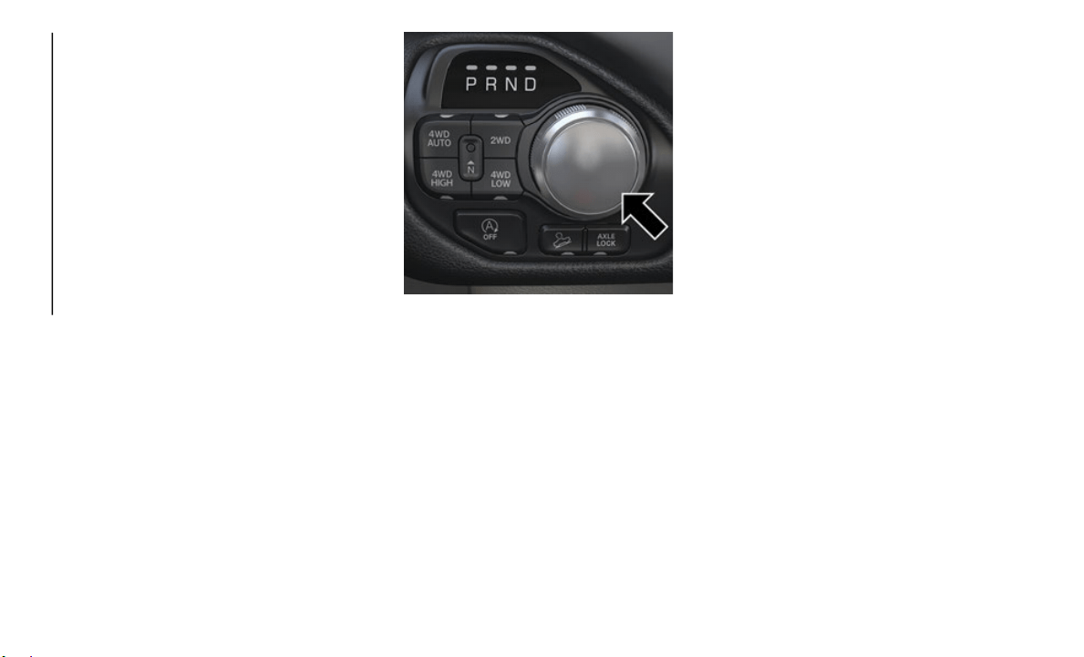
STARTING AND OPERATING
136
This is a normal condition, and precision
shifts will develop within a few hundred
miles (kilometers).
Only shift from DRIVE to PARK or REVERSE
when the
accelerator pedal is released and
the vehicle is stopped. Be sure to keep your
foot on the brake pedal when shifting
between these gears.
The transmission gear selector has only
PARK, REV
ERSE, NEUTRAL, and DRIVE
positions. Manual downshifts can be made
using the Electronic Range Select (ERS)
shift control. Pressing the GEAR-/GEAR+
switches (on the steering wheel) while in the
DRIVE position will select the highest avail
-
able transmission gear, and will display that
gear limi
t in the instrument cluster as 1, 2,
3, etc. Refer to “Electronic Range Select
(ERS) Operation” in this section for further
information. Some models will display both
the selected gear limit, and the actual
current gear, while in ERS mode.
Electronic Transmission Gear Selector
Transmission Limp Home Mode
Transmission function is monitored electron-
ically for abnormal conditions. If a condition
is detect
ed that could result in transmission
damage, Transmission Limp Home Mode is
activated. In this mode, the transmission
may operate only in certain gears, or may not
shift at all. Vehicle performance may be
severely degraded and the engine may stall.
In some situations, the transmission may not
re-engage if the engine is turned off and
restarted. The Malfunction Indicator Light
(MIL) may be illuminated. A message in the
instrument cluster will inform the driver of
the more serious conditions, and indicate
what actions may be necessary.
In the event of a momentary problem, the
transmiss
ion can be reset to regain all
forward gears by performing the following
steps:
NOTE:
In cases where the instrument cluster
message i
ndicates the transmission may not
re-engage after engine shutdown, perform
this procedure only in a desired location
(preferably, at an authorized dealer).
1. Stop the vehicle.
2. Shift
the transmission into PARK, if
possible
. If not, shift the transmission to
NEUTRAL.
3. Push and hold the ignition switch until
the engi
ne turns OFF.
4. Wait approximately 30 seconds.
5. Restar
t the engine.
6. Shift
into the desired gear range. If the
problem
is no longer detected, the trans-
mission will return to normal operation.
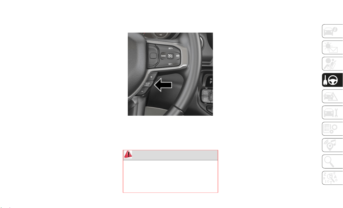
137
NOTE:
Even if the transmission can be reset, we
recommend
that you visit an authorized
dealer at your earliest possible convenience.
An authorized dealer has diagnostic equip
-
ment to assess the condition of your trans-
mission.
If the transmission cannot be reset, autho-
rized dealer service is required.
Electronic Range Select (ERS) Operation —
Eight-Speed Transmission
The Electronic Range Select (ERS) shift
control allows the driver to limit the highest
available gear when the transmission is in
DRIVE. For example, if you set the transmis
-
sion gear limit to 4 (fourth gear), the trans-
mission will not shift above fourth gear
(except t
o prevent engine overspeed), but
will shift through the lower gears normally.
You can switch between DRIVE and ERS
mode at a
ny vehicle speed. When the trans-
mission gear selector is in DRIVE, the trans-
mission will operate automatically, shifting
b
etween a
ll available gears. Tapping the
GEAR- switch (on the steering wheel) will
activate ERS mode, display the current gear
in the instrument cluster, and set that gear
as the top available gear. Once in ERS mode,
tapping the GEAR- or GEAR+ switch will
change the top available gear.
ERS Control
To exit ERS mode, simply push and hold the
G
EAR+ swi
tch until the gear limit display
disappears from the instrument cluster.
FOUR-WHEEL DRIVE
OPERATION — IF EQUIPPED
Four-wheel drive trucks are equipped with
either a manually shifted transfer case or
an electronically shifted transfer case.
Refer to the operating instructions for
electronic transfer case, located in this
section for further information.
For further information on the manually
shifted transfer case, refer to “Four Wheel
Drive Operation” in “Starting And Oper
-
ating” in your Owner’s Manual.
Four-Position Electronically Shifted
Transfer Case (Eight Speed Transmission
Only) — If Equipped
This is an electronic shift transfer case and
is operated by the 4WD Control Switch
(Transfer Case Switch), which is located on
the instrument panel.
WARNING!
Do not downshift for additional engine
braking on a slippery surface. The drive
wheels could lose their grip and the
vehicle could skid, causing a collision or
personal injury.

STARTING AND OPERATING
138
Four-Position/On-Demand Transfer Case —
Eight Speed Transmission Only
This electronically shifted transfer case
provides
four mode positions:
Two-Wheel Drive High Range (2WD)
Four-Wheel Drive High Range (4WD
HIGH)
Four-Wheel Drive Low Range (4WD LOW)
Neutral (NEUTRAL)
For additional information on the appropriate
use of ea
ch transfer case mode position, see
the information below:
2WD
Rear-Wheel Drive High Range — This range
is for no
rmal street and highway driving on
dry, hard-surfaced roads.
4WD HIGH
Four-Wheel Drive High Range — This range
provides
torque to the front driveshaft
(engages four-wheel drive) which allows front
and rear wheels to spin at the same speed.
This provides additional traction for loose
and/or slippery road surfaces.
4WD LOW
Four-Wheel Drive Low Range — This range
provides
low speed four-wheel drive. It maxi-
mizes torque (increased torque over 4WD
H
IGH) to
the front driveshaft; allowing front
and rear wheels to rotate at the same speed.
This range provides additional traction and
maximum pulling power for loose, slippery
road surfaces only. Do not exceed 25
mph
(40 km/h)
in this range.
NEUTRAL (N)
Neutral — This range disengages both the
f
ront and
rear driveshafts from the power-
train. To be used for flat towing behind
a
nother v
ehicle. Refer to “Recreational
Towing” in this section for further informa-
tion.
WARNING!
You or others could be injured or killed if
you leave the vehicle unattended with
the transfer case in the NEUTRAL (N)
position without first fully engaging the
parking brake. The transfer case
NEUTRAL (N) position disengages both
the front and rear drive shaft from the
powertrain, and will allow the vehicle to
roll, even if the transmission is in PARK.
The parking brake should always be
applied when the driver is not in the
vehicle.
The transmission may not engage PARK
if the vehicle is moving. Always bring the
vehicle to a complete stop before
shifting to PARK, and verify that the
transmission gear position indicator
solidly indicates PARK (P) without
blinking. Ensure that the vehicle is
completely stopped, and the PARK posi
-
tion is properly indicated, before exiting
the vehic
le.
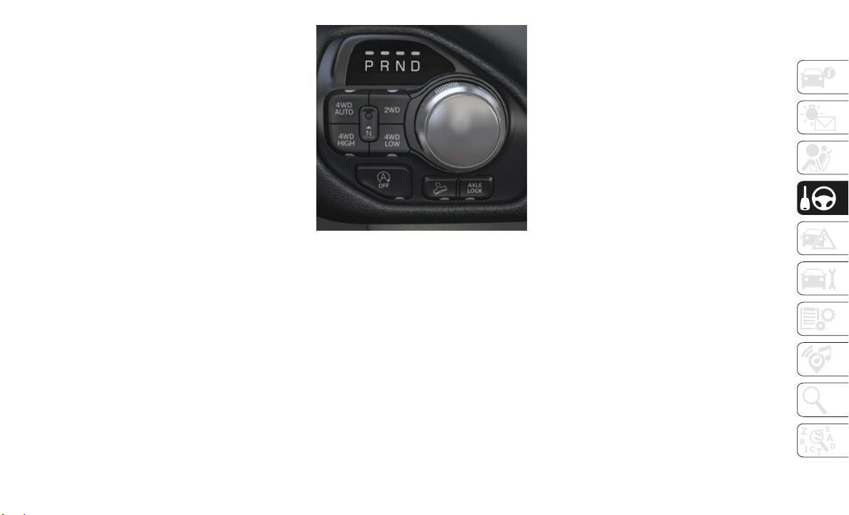
139
This electronically shifted transfer case is
designed to be driven in the two–wheel drive
position (2WD) for normal street and
highway conditions on dry hard surfaced
roads). Driving the vehicle in 2WD will have
greater fuel economy benefits as the front
axle is not engaged in 2WD.
When additional traction is required, the
transfer
case 4WD HIGH and 4WD LOW
positions can be used to maximize torque to
the front driveshaft, forcing the front and
rear wheels to rotate at the same speed. This
is accomplished by pushing the desired posi
-
tion on the 4WD control switch.
Refer to “Shifting Procedure” in the
“
Starting
And Operating” section of your
Owner’s Manual for specific shifting instruc
-
tions.
Five-Position Electronically Shifted
Transfer Case (Eight Speed Transmission
Only) — If Equipped
This is an electronic shift transfer case and
is operated by the 4WD Control Switch
(Transfer Case Switch), which is located on
the instrument panel.
Five-Position/On-Demand Transfer Case —
Eight Speed Transmission Only
This electronically shifted transfer case
provides
five mode positions:
Two-Wheel Drive High Range (2WD)
Four-Wheel Drive Automatic High Range
(4WD AUTO)
Four-Wheel Drive High Range (4WD
HIGH)
Four-Wheel Drive Low Range (4WD LOW)
Neutral (NEUTRAL)
For additional information on the appropriate
use of ea
ch transfer case mode position, see
the information below:
2WD
Rear-Wheel Drive High Range — This range
is for no
rmal street and highway driving on
dry, hard-surfaced roads.
4WD AUTO
Four-Wheel Drive Auto High Range — This
range sen
ds power to the front wheels auto-
matically when the vehicle senses a loss of
t
raction.
This range is used during varying
road conditions.
4WD HIGH
Four-Wheel Drive High Range — This range
provides
torque to the front driveshaft
(engages four-wheel drive) which allows front
and rear wheels to spin at the same speed.
This provides additional traction for loose
and/or slippery road surfaces.
4WD LOW
Four-Wheel Drive Low Range — This range
provides
low speed four-wheel drive. It maxi-
mizes torque (increased torque over 4WD
H
IGH) to
the front driveshaft; allowing front
and rear wheels to rotate at the same speed.

STARTING AND OPERATING
140
(Continued)
This range provides additional traction and
maximum pulling power for loose, slippery
road surfaces only. Do not exceed 25
mph
(40 km/h)
in this range.
NEUTRAL (N)
Neutral — This range disengages both the
f
ront and
rear driveshafts from the power-
train. To be used for flat towing behind
a
nother v
ehicle. Refer to “Recreational
Towing” in this section for further informa
-
tion.
Although 2WD is preferred, this electroni-
cally-shifted transfer case is designed to be
d
riven in
the two-wheel drive position (2WD)
or four-wheel drive position (4WD AUTO) for
normal street and highway conditions on dry,
hard-surfaced roads. Driving the vehicle in
2WD will have greater fuel economy benefits
over any 4WD mode (including 4WD AUTO)
as the front axle is not engaged in 2WD.
For variable driving conditions, the 4WD
AUTO mode
can be used. In this mode, the
front axle is engaged, but the vehicle's power
is sent to the rear wheels. Four-wheel drive
will be automatically engaged when the
vehicle senses a loss of traction. Because the
front axle is engaged, this mode will result in
lower fuel economy than the 2WD mode.
When additional traction is required, the
transfer
case 4WD HIGH and 4WD LOW
positions can be used to maximize torque to
the front driveshaft, forcing the front and
rear wheels to rotate at the same speed. This
is accomplished pushing the desired position
on the 4WD Control Switch.
Refer to “Shifting Procedure” in the
“Starting
And Operating” section of your
Owner’s Manual for further details.
ACTIVE-LEVEL FOUR
CORNER AIR SUSPENSION
SYSTEM — IF EQUIPPED
Description
The air suspension system provides full time
load leveling capability along with the
benefit of being able to adjust vehicle height
by the push of a switch.
WARNING!
You or others could be injured or killed if
you leave the vehicle unattended with
the transfer case in the NEUTRAL (N)
position without first fully engaging the
parking brake. The transfer case
NEUTRAL (N) position disengages both
the front and rear drive shaft from the
powertrain, and will allow the vehicle to
roll, even if the transmission is in PARK.
The parking brake should always be
applied when the driver is not in the
vehicle.
The transmission may not engage PARK
if the vehicle is moving. Always bring the
vehicle to a complete stop before
shifting to PARK, and verify that the
transmission gear position indicator
solidly indicates PARK (P) without
blinking. Ensure that the vehicle is
completely stopped, and the PARK posi
-
tion is properly indicated, before exiting
the vehic
le.
WARNING! (Continued)
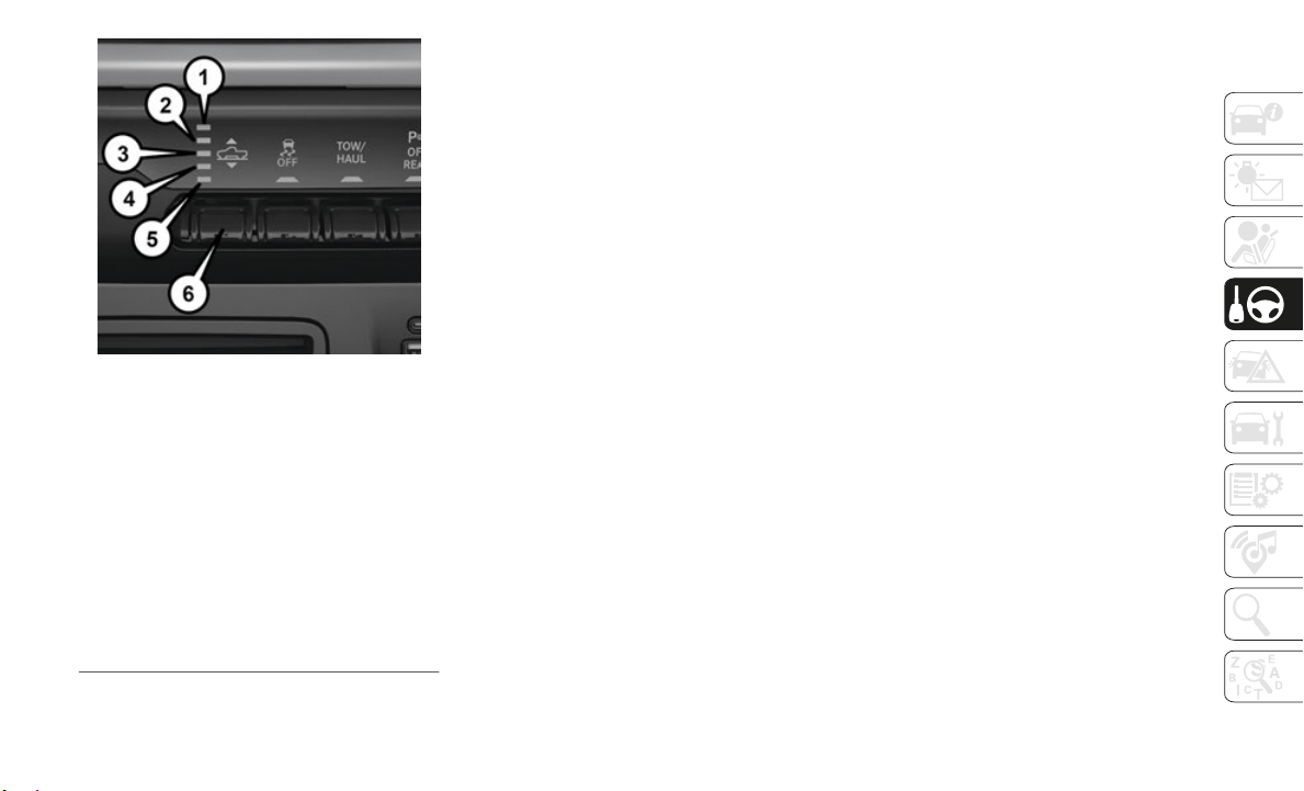
141
1500 Air Suspension Controls
Automatic height changes will occur based
on vehicl
e speed and the current vehicle
height. The indicator lamps and instrument
cluster messages will operate the same for
automatic changes and user requested
changes.
Normal Ride Height (NRH) – This is the
standard position of the suspension and is
meant for normal driving.
Off-Road 1 (OR1) (Raises the vehicle approx-
imately 1 in (26 mm)) - This position
should b
e the primary position for all
off-road driving until Off Road 2 (OR2) is
needed. A smoother and more comfortable
ride will result. To enter OR1, push the
height selector switch up once from the
NRH position while the vehicle speed is
below 35
mph (56 km/h). When in the
OR1 posit
ion, if the vehicle speed remains
between 40
mph (64 km/h) and 50 mph
(80 km/h)
for greater than 20 seconds or
if the ve
hicle speed exceeds 50 mph
(80 km/h),
the vehicle will be automati-
cally lowered to NRH. Off-Road 1 may not
b
e availa
ble due to vehicle payload, an
instrument cluster message will be
displayed when this occurs.
Refer to “Instrument Cluster Display” in
“Getting
To Know Your Instrument Panel”
in the Owner’s Manual for further informa
-
tion.
Off-Road 2 (OR2) (Raises the vehicle approx-
imately 2 in (51 mm)) - This position is
intended
for off-roading use only where
maximum ground clearance is required.
To enter OR2, push the height selector
switch up twice from the NRH position or
once from the OR1 position while vehicle
speed is below 20
mph (32 km/h). While
in OR2, i
f the vehicle speed exceeds
25
mph (40 km/h) the vehicle height will
be automa
tically lowered to OR1.
Off-Road 2
may not be available due to
vehicle p
ayload, an instrument cluster
message will be displayed when this
occurs.
Refer to “Instrument Cluster Display” in
“Getting
To Know Your Instrument Panel”
in the Owner’s Manual for further informa
-
tion.
Aero Mode (Lowers the vehicle approximately
.6 in [15 mm]) – This position provides
improved
aerodynamics by lowering the
vehicle. The vehicle will automatically
enter Aero Mode when the vehicle speed
remains between 62
mph (100 km/h) and
66 mph (106 k
m/h) for greater than 20
seconds o
r if the vehicle speed exceeds
66
mph (106 km/h). The vehicle will
return to
NRH from Aero Mode if the
vehicle speed remains between 30
mph
1 — Off-Road 2 Indicator (Customer Se-
lectable)
2 — Off-Road 1 Indicator (Customer Se-
lectable)
3 — Normal Ride Height Indicator (Cus-
tomer Selectable)
4 — Aero Mode Indicator (Customer Select-
able)
5 — Entry/Exit Mode Indicator (Customer
Selectabl
e)
6 — Height Selector

STARTING AND OPERATING
142
(48 km/h) and 35 mph (56 km/h) for
greater t han 20 seconds or if the vehicle
speed falls below 30
mph (48 km/h).
NOTE:
Speed thresholds for raising the vehicle only
apply if
Automatic Aero Mode is enabled.
To enter Aero Mode manually push the
height se
lector switch down once from
NRH at any vehicle speed. To return to
NRH push the height selector switch up
once while vehicle speed is less than
56
mph (90 km/h).
NOTE:
Automatic Aero Mode may be disabled
t
hrough v
ehicle settings or through your
Uconnect Radio.
Entry/Exit Mode (Lowers the vehicle approxi-
mately 2 in (51 mm)) - This position lowers
the vehi
cle for easier passenger entry and
exit as well as lowering the rear of the
vehicle for easier loading and unloading of
cargo. To enter Entry/Exit Mode, push the
height selector switch down once from the
NHR while the vehicle speed is below
33
mph (53 km/h). Once the vehicle
speed goe
s below 15 mph (24 km/h) the
vehicle h
eight will begin to lower. If the
vehicle speed remains between 15
mph
(24 km/h)
and 25 mph (40 km/h) for
greater t
han 60 seconds, or the vehicle
speed exceeds 25
mph (40 km/h) the
Entry/Exi
t change will be cancelled. To
return to Normal Height Mode, push the
height selector switch up once while in
Entry/Exit or drive the vehicle over 15
mph
(24 km/h).
Entry/Exit mode may not be
available
due to vehicle payload, an instru-
ment cluster message will be displayed
w
hen this
occurs.
Refer to “Instrument Cluster Display” in
“Getting
To Know Your Instrument Panel”
in the Owner’s Manual for further informa
-
tion.
Air Suspension Modes
The Air Suspension system has multiple
modes to protect the system in unique situa-
tions:
Automatic AERO Mode
To improve aerodynamics, the air suspension
s
ystem ha
s a feature which will put the
vehicle into AERO height automatically.
Refer to “Instrument Cluster Display” in
“Getting To Know Your Instrument Panel” in
the Owner’s Manual for further information.
Automatic Aero Mode may be disabled
through vehicle settings or through your
Uconnect Radio.
NOTE:
This mode is intended to be enabled with
engine ru
nning.
Tire Jack Mode
To assist with changing a tire, the air suspen-
sion system has a feature which allows the
a
utomatic
leveling to be disabled. Refer to
“Instrument Cluster Display” in “Getting To
Know Your Instrument Panel” in the Owner’s
Manual for further information.
NOTE:
This mode is intended to be enabled with
e
ngine ru
nning.
Transport Mode
For towing your vehicle with four wheels off
t
he groun
d, the air suspension system has a
feature which will put the vehicle into Entry/
Exit height and disable the automatic load
leveling system. Refer to “Instrument Cluster
Display” in “Getting To Know Your Instru
-
ment Panel” in the Owner’s Manual for
f
urther i
nformation.
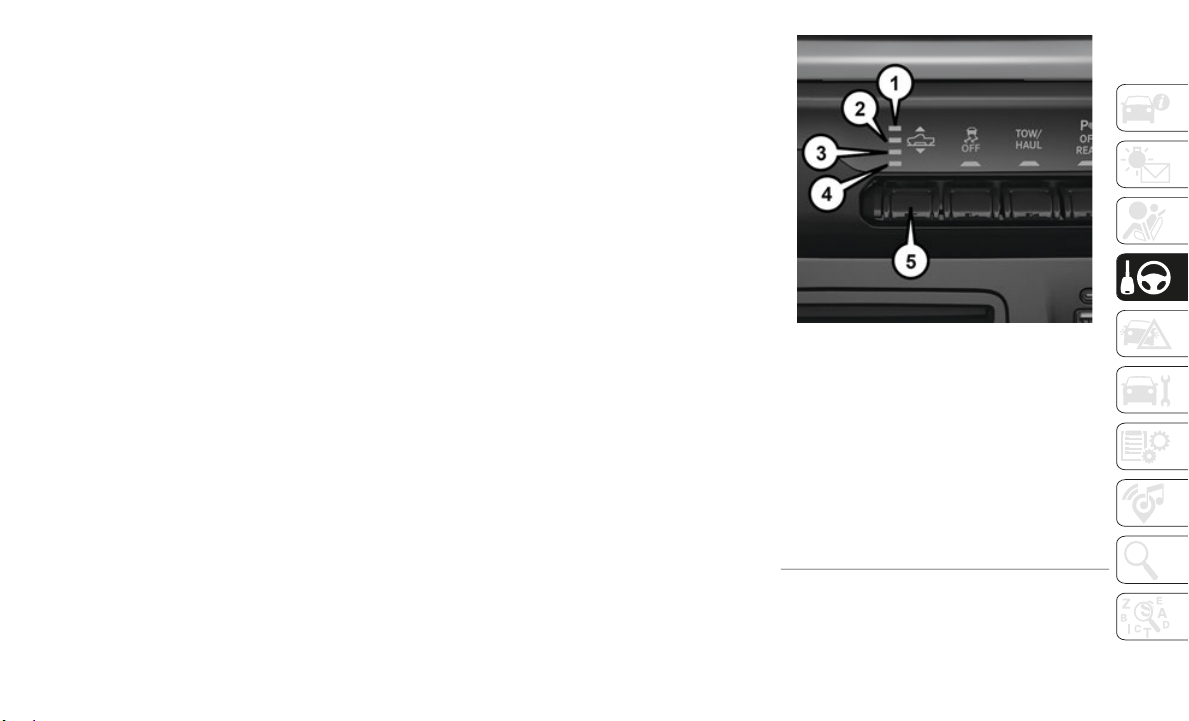
143
NOTE:
This mode is intended to be enabled with
engine ru
nning.
Wheel Alignment Mode
Before performing a wheel alignment, this
m
ode must
be enabled. Refer to “Instrument
Cluster Display” in “Getting To Know Your
Instrument Panel” in the Owner’s Manual for
further information.
NOTE:
This mode is intended to be enabled with
e
ngine ru
nning.
Protection Strategy
In order to “protect” the air suspension
s
ystem, t
he vehicle will disable load leveling
as required (suspension overloaded, battery
charge low, etc.). Load leveling will automat
-
ically resume as soon as system operation
requireme
nts are met. See your authorized
dealer if system does not resume.
NOTE:
If towing with air suspension refer to “Trailer
Towing” i
n “Starting And Operating” for
further information.
ACTIVE-LEVEL FOUR
CORNER AIR SUSPENSION
SYSTEM (REBEL MODELS
ONLY) — IF EQUIPPED
Description
The air suspension system provides full time
load leveling capability along with the
benefit of being able to adjust vehicle height
by the push of a switch.
Automatic height changes will occur based
on vehicl
e speed and the current vehicle
height. The indicator lamps and instrument
cluster messages will operate the same for
automatic changes and user requested
changes.
Rebel Air Suspension Controls
1 — Off-Road Indicator (Customer select-
able)
2 — Normal Ride Height Indicator (Cus-
tomer selectable)
3 — Aerodynamic Height Indicator (Cus-
tomer Selectable)
4— Entry/Exit Mode Indicator (Customer
s
electabl
e)
5 — Height Selector

STARTING AND OPERATING
144
NOTE:
The vehicle will automatically enter Aero Mode
when the
vehicle speed remains between
62
mph (100 km/h) and 66 mph (106 km/h)
for great
er than 20 seconds or if the vehicle
speed exceeds 66
mph (106 km/h).
Normal Ride Height (NRH) – This is the
standard position of the suspension and is
meant for normal driving.
Off-Road (OR) (Raises the vehicle approxi-
mately 1 in (26 mm)) – This position is
intended
for off-roading use only where
maximum ground clearance is required.
To enter OR, push the height selector
switch up once from the NRH position
while vehicle speed is below 20
mph
(32 km/h).
While in OR, if the vehicle
speed exc
eeds 25 mph (40 km/h) the
vehicle h
eight will be automatically
lowered to NRH. Off-Road may not be
available due to vehicle payload, an instru
-
ment cluster display message will be
shown whe
n this occurs.
Refer to “Instrument Cluster Display” in
“Getting
To Know Your Instrument Pan-
el” in your Owner’s Manual for further in-
formation.
Aero Mode (Lowers the vehicle approximately
.6 in (15 mm)) – This position provides
improved
aerodynamics by lowering the
vehicle. The vehicle will automatically
enter Aero Mode when the vehicle speed
remains between 62
mph (100 km/h) and
66 mph (106 k
m/h) for greater than 20
seconds o
r if the vehicle speed exceeds
66
mph (106 km/h). The vehicle will
return to
NRH from Aero Mode if the
vehicle speed remains between 30
mph
(48 km/h) a
nd 35 mph (56 km/h) for
greater t
han 20 seconds or if the vehicle
speed falls below 30
mph (48 km/h).
To enter Aero Mode manually push the
height se
lector switch down once from
NRH at any vehicle speed. To return to
NRH push the height selector switch up
once while vehicle speed is less than
56
mph (90 km/h).
NOTE:
Automatic Aero Mode may be disabled
t
hrough v
ehicle settings on your Uconnect
Radio.
Entry/Exit Mode (Lowers the vehicle approxi-
mately 3 in (73 mm)) – This position lowers
the vehi
cle for easier passenger entry and
exit as well as lowering the rear of the
vehicle for easier loading and unloading of
cargo. To enter Entry/Exit Mode, push the
height selector switch down twice from the
NRH while the vehicle speed is below
33
mph (53 km/h). Once the vehicle
speed goe
s below 15 mph (24 km/h) the
vehicle h
eight will begin to lower. If the
vehicle speed remains between 15
mph
(24 km/h)
and 25 mph (40 km/h) for
greater t
han 60 seconds, or the vehicle
speed exceeds 25
mph (40 km/h) the
Entry/Exi
t change will be cancelled. To
return to Normal Height Mode, push the
height selector switch up twice while in
Entry/Exit or drive the vehicle over 15
mph
(24 km/h).
Entry/Exit mode may not be
available
due to vehicle payload, an instru-
ment cluster display message will be
s
hown whe
n this occurs.
Refer to “Instrument Cluster Display” in
“Getting
To Know Your Instrument Pan-
el” in your Owner’s Manual for further in-
formation.

145
Air Suspension Modes
The Air Suspension system has multiple
modes to protect the system in unique situa-
tions:
AERO Mode
To improve aerodynamics, the air suspension
s
ystem ha
s a feature which will put the
vehicle into AERO height automatically.
Refer to “Instrument Cluster Display” in
“Getting To Know Your Instrument Panel” in
the Owner’s Manual for further information.
NOTE:
This mode is intended to be enabled with
engine ru
nning.
Tire Jack Mode
To assist with changing a tire, the air suspen-
sion system has a feature which allows the
a
utomatic
leveling to be disabled. Refer to
“Instrument Cluster Display” in “Getting To
Know Your Instrument Panel” in the Owner’s
Manual for further information.
NOTE:
This mode is intended to be enabled with
e
ngine ru
nning.
Transport Mode
For towing your vehicle with four wheels off
the groun
d, the air suspension system has a
feature which will put the vehicle into Entry/
Exit height and disable the automatic load
leveling system. Refer to “Instrument Cluster
Display” in “Getting To Know Your Instru
-
ment Panel” in the Owner’s Manual for
f
urther i
nformation.
NOTE:
This mode is intended to be enabled with
e
ngine ru
nning.
Wheel Alignment Mode
Before performing a wheel alignment, this
m
ode must
be enabled. Refer to “Instrument
Cluster Display” in “Getting To Know Your
Instrument Panel” in the Owner’s Manual for
further information.
NOTE:
This mode is intended to be enabled with
e
ngine ru
nning.
Protection Strategy
In order to “protect” the air suspension
s
ystem, t
he vehicle will disable load leveling
as required (suspension overloaded, battery
charge low, etc.). Load leveling will automat
-
ically resume as soon as system operation
r
equireme
nts are met. See your authorized
dealer if system does not resume.
NOTE:
If towing with air suspension refer to “Trailer
Towing” i
n “Starting And Operating” for
further information.
AXLE LOCKER SYSTEM — IF
EQUIPPED
This vehicle is equipped with an electroni-
cally locking rear differential. This differen-
tial, when engaged, mechanically lock
together the axle shafts forcing the wheels to
spin at an equal rate. The locking of the rear
differential should only be engaged during
low-speed, extreme off-road situations where
one wheel is likely to not be in contact with
the ground. It is not recommended to drive
the vehicle with the differentials locked on
pavement due to the reduced ability to turn
and speed limitations.

STARTING AND OPERATING
146
Axle Lock Button
The locking rear axle is controlled by the
AXLE LOCK
ER button.
Under normal driving conditions, the rear
axle shou
ld be unlocked.
During the command to lock the rear axle,
the indic
ator light will flash until the axle is
locked. After the lock command has been
successfully executed, the light will remain
on solid.
Operating in 4WD LOW the locker can be
engaged u
p to 40 mph (64 km/h) and will
remain en
gaged throughout the 4WD LOW
speed range.
Operating the locker in 2WD, 4WD AUTO,
and 4WD L
OCK/HIGH the locker can be
engaged up to 20
mph (32 km/h). While
driving w
ith the locker engaged, if speed
exceeds 25
mph (40 km/h), the locker will
automatic
ally disengage, but will automati-
cally reengage at 20 mph (32 km/h).
NOTE:
Left to right wheel speed difference may be
n
ecessary
to allow the rear axle to fully lock.
If the indicator light is flashing after
selecting the rear axle lock mode, drive the
vehicle in a turn or on loose gravel to expe
-
dite the locking action.
The axle locker could become torque locked
d
ue to si
de to side loads on the rear axle.
Driving slowly while turning the steering
wheel from a left hand turn to a right hand
turn or driving in REVERSE for a short
distance may be required to release the
torque lock and unlock the axles.
To unlock the rear axle; push the AXLE LOCK
button. T
he AXLE LOCK indicator light will
go out when the rear axle is unlocked.
LIMITED-SLIP
DIFFERENTIAL — IF
EQUIPPED
The limited-slip differential provides addi-
tional traction on snow, ice, mud, sand and
gravel, p
articularly when there is a difference
between the traction characteristics of the
surface under the right and left rear wheels.
During normal driving and cornering, the
limited-slip unit performs similarly to a
conventional differential. On slippery
surfaces, however, the differential delivers
more of the driving effort to the rear wheel
having the better traction.
The limited-slip differential is especially
helpful d
uring slippery driving conditions.
With both rear wheels on a slippery surface,
CAUTION!
Do not lock the rear axle on hard
surfaced roads. The ability to steer the
vehicle is reduced and damage to the
drivetrain may occur when the axle is
locked on hard surfaced roads.
Do not try to lock the rear axle if the
vehicle is stuck and the tires are spin-
ning. You can damage drivetrain compo-
nents. Lock the rear axle before
a
ttemptin
g situations or navigating
terrain, which could possibly cause the
vehicle to become stuck.
147
a slight application of the accelerator will
supply maximum traction. When starting
with only one rear wheel on an excessively
slippery surface, slight momentary applica
-
tion of the parking brake may be necessary to
gain maxi
mum traction.
Care should be taken to avoid sudden accel-
erations when both rear wheels are on a slip-
pery surface. This could cause both rear
w
heels to
spin, and allow the vehicle to slide
sideways on the crowned surface of a road or
in a turn.
STOP/START SYSTEM — IF
EQUIPPED
The Stop/Start function is developed to save
fuel and reduce emissions. The system will
stop the engine automatically during a
vehicle stop if the required conditions are
met. Releasing the brake pedal will automat-
ically restart the engine.
Vehicles equipped with eTorque contain a
h
eavy dut
y motor generator and an additional
hybrid electric battery to store energy from
vehicle deceleration for use on engine
startup after a stop as well as providing
launch torque assist.
Automatic Mode
The Stop/Start feature is enabled after every
normal customer engine start. It will remain
in STOP/START NOT READY until you drive
forward with a vehicle speed greater than
2
mph (3 km/h). At that time, the system
will go i
nto STOP/START READY and if all
other conditions are met, can go into an
STOP/START AUTO STOP ACTIVE
“Autostop” mode.
To Activate The Autostop Mode, The Following
Must Occu
r:
1. The system must be in STOP/START
READY st
ate. A STOP/START READY
message will be displayed in the instru
-
ment cluster within the Stop/Start
section.
Refer to “Instrument Cluster
Display” in “Getting To know Your Instru-
ment Panel” for further information.
2. The vehicle must be completely stopped.
3. The tr
ansmission Gear Selector must be
in DRIVE
and the brake pedal depressed.
The engine will shut down, the tachometer
will move
to the zero position and the stop/
start telltale will illuminate indicating you
are in an Autostop. While in an Autostop, the
Climate Controls system may automatically
adjust airflow to maintain cabin comfort.
Customer settings will be maintained upon
return to an engine running condition.
Possible Reasons The Engine Does Not
Autostop
Prior to engine shut down, the system will
check many safety and comfort conditions to
see if they are fulfilled. In following situa
-
tions, the engine will not Autostop:
Driver’s seat belt is not buckled.
Driver’s door is not closed.
WARNING!
When servicing vehicles equipped with a
limited-slip or locking differential never
run the engine with one rear wheel off the
ground since the vehicle may drive through
the rear wheel remaining on the ground
and result in unintended movement.

STARTING AND OPERATING
148
The vehicle is on a steep grade.
Cabin heating or cooling is in process and
an acceptable cabin temperature has not
been achieved.
HVAC is set to full defrost mode at a high
blower speed.
Engine has not reached normal operating
temperature.
Engine temperature too high.
The battery is charging.
The transmission is not in DRIVE.
Hood is open.
Vehicle is in 4LO transfer case mode.
Accelerator pedal input.
Excessive 12 volt loads.
It may be possible to operate the vehicle
several c
onsecutive times in extreme condi-
tions and not meet all criteria to enable an
A
utostop
state.
To Start The Engine While In Autostop
Mode
While in DRIVE, the engine will start when
the brake pedal is released or the throttle
pedal is depressed and the transmission will
automatically reengage upon engine restart.
Conditions That Will Cause The Engine To Start
Automatic
ally While In Autostop Mode
The engine will start automatically when:
The transmission selector is moved from
DRIVE to REVERSE, NEUTRAL, or PARK.
To maintain cabin temperature near the
HVAC settings.
HVAC is set to full defrost mode.
12 volt demand requires engine restart.
Low brake vacuum (e.g. after several brake
pedal applications).
STOP/START OFF switch is pushed.
4WD system is put into 4LO mode.
The emissions system override is present.
A STOP/START system error present.
Conditions That Force An Automatic Shift To
Park Whil
e In Autostop Mode
The engine will not start automatically and
the trans
mission will be placed in PARK if:
The driver door is open and brake pedal
released.
The driver door is open and the driver seat
belt is unbuckled.
The engine hood has been opened.
A STOP/START system error present.
The engine may then be restarted by moving
the trans
mission shift selector out of PARK
(e.g. to DRIVE) or, in some cases, only by a
KEY START. The instrument cluster will
display a SHIFT OUT OF PARK message, or
a STOP/START KEY START REQUIRED
message, to indicate which action is
required.
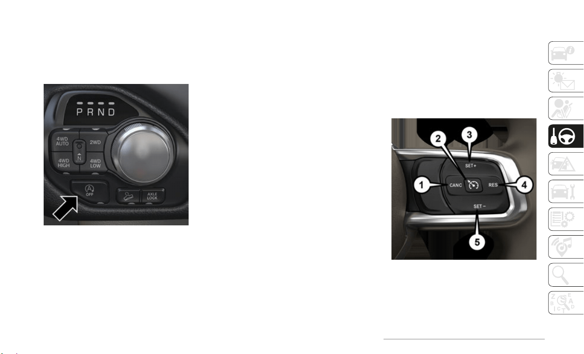
149
To Manually Turn Off The Stop Start
System
1. Push the STOP/START Off switch
(located near the gear selector). The light
on the switch will illuminate.
STOP/START OFF Switch
2. The STOP/START OFF message will
appear i
n the instrument cluster display.
Refer to “Instrument Cluster Display” in
“Getting To Know Your Instrument
Panel” for further information.
3. At the next vehicle stop (after turning off
the STOP
/START system) the engine will
not be stopped.
4. If the STOP/START system is manually
turned o
ff, the engine can be started and
stopped by cycling the ignition switch or
pressing the STOP/START switch again.
5. The STOP/START system will reset itself
back to
an ON condition every time the
key is turned off and back on.
To Manually Turn On The Stop Start
System
1. Push the STOP/START Off switch
(located near the gear selector module).
2. The light on the switch will turn off.
System Malfunction
If there is a malfunction in the STOP/START
system, the system will not shut down the
engine. A “SERVICE STOP/START SYSTEM”
message will appear in the instrument
cluster display. Refer to “Instrument Cluster
Display” in “Getting To Know Your Instru
-
ment Panel” for further information.
The system will need to be checked by your
a
uthorize
d dealer.
SPEED CONTROL — IF
EQUIPPED
When engaged, the Speed Control takes over
accelerator operations at speeds greater than
20
mph (32 km/h).
The Speed Control buttons are located on the
right sid
e of the steering wheel.
Speed Control Buttons
1 — CANC/Cancel
2 — On/Off
3 — SET (+)/Accel
4 — RES/Resume
5 — SET (-)/Decel

STARTING AND OPERATING
150
NOTE:
In order to ensure proper operation, the
Speed Control System has been designed
to shut down if multiple Speed Control
functions are operated at the same time. If
this occurs, the Speed Control System can
be reactivated by pushing the Speed
Control on/off button and resetting the
desired vehicle set speed.
To Activate
Push the On/Off button to activate the Speed
Control. The cruise indicator light in the
instrument cluster display will illuminate. To
turn the system off, push the On/Off button
a second time. The cruise indicator light will
turn off. The system should be turned off
when not in use.
To Set A Desired Speed
Turn the Speed Control on.
NOTE:
The vehicle should be traveling at a steady
speed and
on level ground before pushing
the SET (+) or SET (-) button.
When the vehicle has reached the desired
speed, pu
sh the SET (+) or SET (-) button
and release. Release the accelerator and the
vehicle will operate at the selected speed.
To Resume Speed
To resume a previously set speed, push the
RES button and release. Resume can be
used at any speed above 20
mph (32 km/h).
To Deactivate
A soft tap on the brake pedal, pushing the
CANC (cancel) button, or normal brake pres-
sure while slowing the vehicle will deactivate
t
he speed
control without erasing the set
speed from memory.
Pushing the on/off button or cycling the igni-
tion to OFF, erases the set speed from
memory.
Using Speed Control On Hills
The transmission may downshift on hills to
maintain the vehicle set speed.
NOTE:
The Speed Control system maintains speed
u
p and do
wn hills. A slight speed change on
moderate hills is normal.
On steep hills, a greater speed loss or gain
may occur
so it may be preferable to drive
without Speed Control.
WARNING!
Speed Control can be dangerous where the
system cannot maintain a constant speed.
Your vehicle could go too fast for the
conditions, and you could lose control and
have an accident. Do not use Speed
Control in heavy traffic or on roads that are
winding, icy, snow-covered or slippery.
WARNING!
Leaving the Speed Control system on when
not in use is dangerous. You could
accidentally set the system or cause it to
go faster than you want. You could lose
control and have an accident. Always leave
the system off when you are not using it.
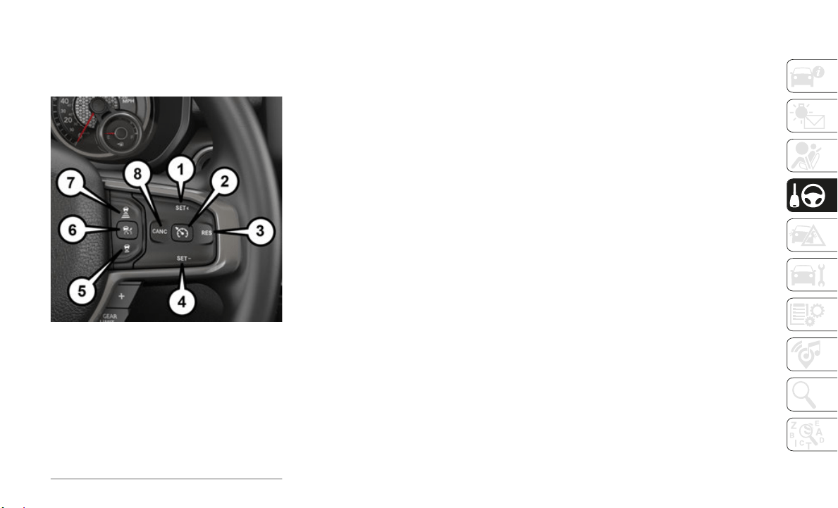
151
ADAPTIVE CRUISE
CONTROL (ACC)
OPERATION
Adaptive Cruise Control Buttons
If your vehicle is equipped with Adaptive
Cruise Co
ntrol, the controls operate exactly
the same as Speed Control with only a couple
of differences. With this option, you can set
a specified distance you would like to main
-
tain between you and the vehicle in front of
you.
If the
ACC sensor detects a vehicle ahead,
ACC will
apply limited braking or accelera-
tion automatically to maintain a preset
f
ollowing
distance, while matching the speed
of the vehicle ahead.
If the sensor does not detect a vehicle ahead
of you, A
CC will maintain a fixed set speed.
NOTE:
Any chassis/suspension or tire size modifica-
tions to the vehicle will effect the perfor-
mance of the Adaptive Cruise Control and
F
orward C
ollision Warning System.
Activation
Push and release the Adaptive Cruise Control
(ACC) on/off button.
“ACC READY” will appear in the instrument
cluster d
isplay to indicate the ACC is on.
To Set A Desired ACC Speed
When the vehicle reaches the speed desired,
push the SET (+) button or the SET (-) button
and release. The instrument cluster display
will show the set speed.
If the system is set when the vehicle speed is
below 20 m
ph (32 km/h), the set speed shall
be defaul
ted to 20 mph (32 km/h). If the
system is
set when the vehicle speed is
above 20
mph (32 km/h), the set speed shall
be the cu
rrent speed of the vehicle.
NOTE:
ACC cannot be set if there is a stationary
v
ehicle i
n front of your vehicle in close prox-
imity.
Remove your foot from the accelerator pedal,
a
fter the
ACC has been set. If you do not, the
vehicle may continue to accelerate beyond
the set speed. If this occurs:
The message “ACC DRIVER OVERRIDE”
will display in the instrument cluster
display.
The system will not be controlling the
distance between your vehicle and the
vehicle ahead. The vehicle speed will only
be determined by the position of the
accelerator pedal.
1 — SET+/Accel 5 — Distance Setting
Decrease
2
— Normal (Fixed
Speed) Cr
uise Con-
trol On/Off
6 — Adaptive Cruise
C
ontrol (ACC) On/Off
3 — RES/Resume 7 — Distance Setting
Increase
4
— SET-/Decel 8 — CANC/Cancel

STARTING AND OPERATING
152
To Vary The Speed Setting
To Increase Speed
While ACC is set, you can increase the set
speed by
pushing the SET (+) button.
The speed increment shown is dependant on
the chose
n speed unit of U.S. (mph) or Metric
(km/h):
U.S. Speed (mph)
Pushing the SET (+) button once will result
in a 1 mph increase in set speed. Each
subsequen
t tap of the button results in an
increase of 1
mph.
If the button is continually pushed, the set
speed will continue to increase in 5 mph
increment
s until the button is released. The
increase in set speed is reflected in the
instrument cluster display.
Metric Speed (km/h)
Pushing the SET (+) button once will result
in a 1 km/h increase in set speed. Each
subsequen
t tap of the button results in an
increase of 1
km/h.
If the button is continually pushed, the set
speed will continue to increase in 10 km/h
increment
s until the button is released. The
increase in set speed is reflected in the
instrument cluster display.
To Decrease Speed
While ACC is set, the set speed can be
decreased
by pushing the SET (-) button.
The speed decrement shown is dependant on
the chose
n speed unit of U.S. (mph) or Metric
(km/h):
U.S. Speed (mph)
Pushing the SET (-) button once will result in
a 1 mph decrease in set speed. Each subse-
quent tap of the button results in a decrease
o
f 1 mph.
If the button is continually pushed, the set
speed will continue to decrease in 5 mph
increment
s until the button is released. The
decrease in set speed is reflected in the
instrument cluster display.
Metric Speed (km/h)
Pushing the SET (-) button once will result in
a 1 km/h decrease in set speed. Each subse-
quent tap of the button results in a decrease
o
f 1 km/h.
If the button is continually pushed, the set
speed will continue to decrease in 10 km/h
increment
s until the button is released. The
decrease in set speed is reflected in the
instrument cluster display.
NOTE:
When you override and push the SET (+)
button or SET (-) buttons, the new set speed
will be the current speed of the vehicle.
When you use the SET (-) button to decel-
erate, if the engine’s braking power does not
slow the
vehicle sufficiently to reach the set
speed, the brake system will automatically
slow the vehicle.
The ACC system decelerates the vehicle to a
full stop when following a target vehicle. If
an ACC host vehicle follows a target vehicle
to a standstill, after two seconds the driver
will either have to push the RES (resume)
button, or apply the accelerator pedal to
reengage the ACC to the existing set speed.
The ACC system maintains set speed when
driving up hill and down hill. However, a
slight speed change on moderate hills is
normal. In addition, downshifting may occur
while climbing uphill or descending down
-
hill. This is normal operation and necessary
to mainta
in set speed. When driving up hill
and down hill, the ACC system will cancel if
the braking temperature exceeds normal
range (overheated).
153
To Resume
If there is a set speed in memory push the
RES (resume) button and then remove your
foot from the accelerator pedal. The instru
-
ment cluster display will display the last set
speed.
NOTE
:
If your vehicle stays at standstill for longer
than two seconds, then the driver will
either have to push the RES (resume)
button, or apply the accelerator pedal to
reengage the ACC to the existing set
speed.
ACC cannot be resumed if there is a
stationary vehicle in-front of your vehicle
in close proximity.
Deactivation
Push and release the Adaptive Cruise Control
(ACC) on/off button a second time to turn the
system off.
“Adaptive Cruise Control (ACC) Off” will
appear in
the instrument cluster display to
indicate the ACC is off.
Setting The Following Distance In ACC
The specified following distance for ACC can
be set by varying the distance setting
between four bars (longest), three bars
(long), two bars (medium) and one bar
(short). Using this distance setting and the
vehicle speed, ACC calculates and sets the
distance to the vehicle ahead. This distance
setting displays in the instrument cluster
display.
To increase the distance setting, push the
Distance
Setting — Increase button and
release. Each time the button is pushed, the
distance setting increases by one bar
(longer).
To decrease the distance setting, push the
Distance
Setting — Decrease button and
release. Each time the button is pushed, the
distance setting decreases by one bar
(shorter).
If there is no vehicle ahead, the vehicle will
maintain
the set speed. If a slower moving
vehicle is detected in the same lane, the
instrument cluster displays the “Sensed
Vehicle Indicator” icon, and the system
adjusts vehicle speed automatically to main
-
tain the distance setting, regardless of the
s
et speed
.
The vehicle will then maintain the set
distance
until:
The vehicle ahead accelerates to a speed
above the set speed.
The vehicle ahead moves out of your lane
or view of the sensor.
The distance setting is changed.
The system disengages. (Refer to the
information on ACC Activation).
WARNING!
The Resume function should only be used
if traffic and road conditions permit.
Resuming a set speed that is too high or
too low for prevailing traffic and road
conditions could cause the vehicle to
accelerate or decelerate too sharply for
safe operation. Failure to follow these
warnings can result in a collision and
death or serious personal injury.
WARNING!
Leaving the ACC system on when not in
use is dangerous. You could accidentally
set the system or cause it to go faster than
you want. You could lose control and have
an accident. Always leave the system OFF
when you are not using it.

STARTING AND OPERATING
154
The maximum braking applied by ACC is
limited; however, the driver can always apply
the brakes manually, if necessary.
NOTE:
The brake lights will illuminate whenever the
ACC syste
m applies the brakes.
A Proximity Warning will alert the driver if
ACC predi
cts that its maximum braking level
is not sufficient to maintain the set distance.
If this occurs, a visual alert “BRAKE” will
flash in the instrument cluster display and a
chime will sound while ACC continues to
apply its maximum braking capacity.
NOTE:
The “Brake!” Screen in the instrument
cluster d
isplay is a warning for the driver to
take action and does not necessarily mean
that the Forward Collision Warning system is
applying the brakes autonomously.
ACC Operation At Stop
In the event that the ACC system brings your
vehicle to a standstill while following a target
vehicle, if the target vehicle starts moving
within two seconds of your vehicle coming to
a standstill, your vehicle will resume motion
without the need for any driver action.
If the target vehicle does not start moving
within tw
o seconds of your vehicle coming to
a standstill, the driver will either have to
push the RES (resume) button, or apply the
accelerator pedal to reengage the ACC to the
existing Set Speed.
NOTE:
After the ACC system holds your vehicle at a
standstil
l for approximately 3 consecutive
minutes, the parking brake will be activated,
and the ACC system will be cancelled.
While ACC is holding your vehicle at a stand-
still, if the driver seatbelt is unbuckled or the
driver do
or is opened, the parking brake will
be activated, and the ACC system will be
cancelled.
Changing Modes
If desired, the Adaptive Cruise Control mode
can be turned off and the system can be
operated as a Normal (Fixed Speed) Cruise
Control mode. When in the Normal (Fixed
Speed) Cruise Control mode the distance
setting feature will be disabled and the
system will maintain the speed you set.
To change between the different cruise
control modes, push the Adaptive Cruise
Control (ACC) on/off button which turns
the ACC and the Normal (Fixed Speed)
Cruise Control off.
Pushing the Normal (Fixed Speed) Cruise
Control on/off button will result in turning
on (changing to) the Normal (Fixed Speed)
Cruise Control mode.
Refer to your Owner's Manual for further
informati
on.
WARNING!
When the ACC system is resumed, the
driver must ensure that there are no
pedestrians, vehicles or objects in the path
of the vehicle. Failure to follow these
warnings can result in a collision and
death or serious personal injury.
155
(Continued)
(Continued)
General Information
The following regulatory statement applies to
all Radio Frequency (RF) devices equipped
in this vehicle:
This device complies with Part 15 of the FCC
Rules and
with Industry Canada
license-exempt RSS standard(s). Operation
is subject to the following two conditions:
1. This device may not cause harmful inter-
ference.
2
. This device must accept any interference
received
, including interference that may
cause undesired operation.
WARNING!
Adaptive Cruise Control (ACC) is a convenience
system. It is not a substitute for active driving
involvement. It is always the driver’s
responsibility to be attentive of road, traffic,
and weather conditions, vehicle speed,
distance to the vehicle ahead; and, most
importantly, brake operation to ensure safe
operation of the vehicle under all road
conditions. Your complete attention is always
required while driving to maintain safe control
of your vehicle. Failure to follow these warnings
can result in a collision and death or serious
personal injury.
The ACC system:
Does not react to pedestrians, oncoming vehi-
cles, and stationary objects (e.g., a stopped
vehicle i
n a traffic jam or a disabled vehicle).
Cannot take street, traffic, and weather
conditions into account, and may be limited
upon adverse sight distance conditions.
Does not always fully recognize complex
driving conditions, which can result in wrong
or missing distance warnings.
Will bring the vehicle to a complete stop
while following a target vehicle and hold the
vehicle for 2 seconds in the stop position. If
the target vehicle does not start moving
within two seconds the ACC system will
display a message that the system will
release the brakes and that the brakes must
be applied manually. An audible chime will
sound when the brakes are released.
You should switch off the ACC system:
When driving in fog, heavy rain, heavy snow,
sleet, heavy traffic, and complex driving situ-
ations (i.e., in highway construction zones).
When entering a turn lane or highway off
ramp; when driving on roads that are winding,
icy, snow-covered, slippery, or have steep
uphill or downhill slopes.
When towing a trailer up or down steep
slopes.
When circumstances do not allow safe driving
at a constant speed.
The Cruise Control system has two control
modes:
Adaptive Cruise Control mode for maintaining
an appropriate distance between vehicles.
WARNING! (Continued)
Normal (Fixed Speed) Cruise Control mode
for cruising at a constant preset speed. For
additional information, refer to “Normal
(Fixed Speed) Cruise Control Mode” in your
Owner’s Manual.
Normal (Fixed Speed) Cruise Control will not
react to
preceding vehicles. Always be aware of
the mode selected.
You can change the mode by using the Cruise
Control b
uttons. The two control modes
function differently. Always confirm which
mode is selected.
WARNING! (Continued)

STARTING AND OPERATING
156
NOTE:
Changes or modifications not expressly
approved
by the party responsible for compli-
ance could void the user’s authority to
o
perate t
he equipment.
PARKSENSE FRONT AND
REAR PARK ASSIST
The ParkSense Park Assist system provides
visual and audible indications of the
distance between the rear and/or front fascia
and a detected obstacle when backing up or
moving forward, e.g. during a parking
maneuver. If your vehicle is equipped with
the automatic braking function, the vehicle
brakes may be automatically applied and
released when performing a reverse parking
maneuver if the system detects a possible
collision with an obstacle.
NOTE:
The driver can override the automatic
braking function by pressing the gas
pedal, turning ParkSense off via Park
-
Sense switch, or changing the gear while
the autom
atic brakes are being applied.
Automatic brakes will not be available if
ESC is not available.
Automatic brakes will not be available if
there is a faulted condition detected with
the ParkSense Park Assist system or the
Braking System Module.
The automatic braking function may only
be applied if the vehicle deceleration is
not enough to avoid colliding with a
detected obstacle.
The automatic braking function will not be
available if vehicle is in 4LO transfer case
mode.
The automatic braking function may not
be applied fast enough for obstacles that
move toward the rear of the vehicle from
the left and/or right sides.
The automatic braking function can be
enabled/disabled from the Customer
Programmable Features section of the
Uconnect System.
ParkSense will retain its last known
configuration state for the automatic
braking function through ignition cycles.
The driver can override the automatic
braking function by pressing the gas
pedal, turning the rear system ParkSense
off via the Rear ParkSense switch, or
changing the gear while the automatic
brakes are being applied.
The automatic braking function is intended
to assist
the driver in avoiding possible colli-
sions with detected obstacles when backing
u
p in REV
ERSE gear.
NOTE:
The driver is always responsible for
controlling the vehicle.
The system is provided to assist the driver
and not to substitute the driver.
The driver must stay in full control of the
vehicle's acceleration and braking and is
responsible for the vehicle's movements.
Refer to “ParkSense System Usage Precau-
tions” in this section for limitations of this
system an
d recommendations.
ParkSense will retain the last system state
(enabled
or disabled) from the last ignition
cycle when the ignition is changed to the ON/
RUN position.
ParkSense can be active only when the gear
selector
is in REVERSE or DRIVE. If Park-
Sense is enabled at one of these gear
s
elector
positions, the system will remain
active until the vehicle speed is increased to
approximately 7
mph (11 km/h) or above. A
warning w
ill appear in the instrument cluster
display indicating the vehicle is above Park
-

157
Sense operating speed when the vehicle is in
REVERSE. The system will become active
again if the vehicle speed is decreased to
speeds less than approximately 6
mph
(9 km/h).
ParkSense Sensors
The four ParkSense sensors (six, if vehicle is
equipped with Active ParkSense), located in
the rear fascia/bumper, monitor the area
behind the vehicle that is within the sensors’
field of view. The sensors can detect obsta
-
cles from approximately 12 inches (30 cm)
up to 79 i
nches (200 cm) from the rear
fascia/bu
mper in the horizontal direction,
depending on the location, type and orienta
-
tion of the obstacle.
The six ParkSense sensors, located in the
front fas
cia/bumper, monitor the area in
front of the vehicle that is within the sensors’
field of view. The sensors can detect obsta
-
cles from approximately 12 inches (30 cm)
up to 47 i
nches (120 cm) from the front
fascia/bu
mper in the horizontal direction,
depending on the location, type and orienta
-
tion of the obstacle.
ParkSense Warning Display
The ParkSense Warning screen is located
within the instrument cluster display. It
provides visual warnings to indicate the
distance between the rear fascia/bumper
and/or front fascia/bumper and the detected
obstacle.
Refer to “Instrument Cluster Display” in
“Getting
To Know Your Instrument Panel” in
the Owner’s Manual for further information.
Enabling And Disabling Front And/Or
Rear ParkSense
Front ParkSense can be enabled and
disabled with the Front ParkSense switch.
Rear ParkSense can be enabled and disabled
with the
Rear ParkSense switch.
When the Front or Rear ParkSense
switch is pushed to disable the
s
ystem, t
he instrument cluster
display will show a vehicle graphic
of the Front or Rear ParkSense on/off state
for two seconds.
Refer to “Instrument Cluster Display” in
“Getting
To Know Your Instrument Panel” in
the Owner’s Manual for further information.
When the gear selector is moved to
REVERSE a
nd the Front or Rear system is
disabled, the instrument cluster display will
show a vehicle graphic with "OFF" on the
corresponding side. This vehicle graphic will
be displayed for as long as the vehicle is in
REVERSE.
NOTE:
Arc alerts from the enabled ParkSense
s
ystem, w
ill interrupt the five second
messages, and the instrument cluster
display will show the vehicle graphic with the
corresponding arcs and "OFF" message.
The Front or Rear ParkSense switch LED will
be on whe
n Front or Rear ParkSense is
disabled or requires service. The Front or
Rear ParkSense switch LED will be off when
the Front or Rear system is enabled. If the
Front or Rear ParkSense switch is pushed,
and the system requires service, the Front or
Rear ParkSense switch LED will blink
momentarily, and then the LED will be on.
ParkSense System Usage Precautions
NOTE:
Ensure that the front and rear bumper are
free of snow, ice, mud, dirt and debris to
keep the ParkSense system operating
properly.
Jackhammers, large trucks, and other
vibrations could affect the performance of
ParkSense.

STARTING AND OPERATING
158
When you turn Front or Rear ParkSense
off, the instrument cluster display will
show a vehicle graphic of the Front and
Rear ParkSense on/off state for two
seconds. Furthermore, once you turn Front
or Rear ParkSense off, it remains off until
you turn it on again, even if you cycle the
ignition key.
When you move the gear selector to the
REVERSE position and Front or Rear Park-
Sense is turned off, the instrument cluster
d
isplay w
ill show a vehicle graphic with
"OFF" in the corresponding side. This
vehicle graphic will be displayed for as
long as the vehicle is in REVERSE.
ParkSense, when on, will reduce the
volume of the radio when it is sounding a
tone.
Clean the ParkSense sensors regularly,
taking care not to scratch or damage them.
The sensors must not be covered with ice,
snow, slush, mud, dirt or debris. Failure to
do so can result in the system not working
properly. The ParkSense system might not
detect an obstacle behind or in front of the
fascia/bumper, or it could provide a false
indication that an obstacle is behind or in
front of the fascia/bumper.
Use the ParkSense switch to turn the
ParkSense system off if obstacles such as
bicycle carriers, trailer hitches, etc. are
placed within 12
inches (30 cm) from the
rear fasc
ia/bumper. Failure to do so can
result in the system misinterpreting a
close obstacle as a sensor problem,
causing the “PARKSENSE UNAVAILABLE
SERVICE REQUIRED” or “Service”
message to appear in the instrument
cluster display.
On vehicles equipped with a tailgate,
ParkSense should be disabled when the
tailgate is in the lowered or open position.
A lowered tailgate could provide a false
indication that an obstacle is behind the
vehicle.
WARNING!
Drivers must be careful when backing up
even when using ParkSense. Always
check carefully behind your vehicle, look
behind you, and be sure to check for
pedestrians, animals, other vehicles,
obstructions, and blind spots before
backing up. You are responsible for
safety and must continue to pay atten
-
tion to your surroundings. Failure to do
so can re
sult in serious injury or death.
Before using ParkSense, it is strongly
recommended that the ball mount and
hitch ball assembly is disconnected from
the vehicle when the vehicle is not used
for towing. Failure to do so can result in
injury or damage to vehicles or obstacles
because the hitch ball will be much
closer to the obstacle than the rear fascia
when the loudspeaker sounds the contin
-
uous tone. Also, the sensors could detect
t
he ball
mount and hitch ball assembly,
depending on its size and shape, giving
a false indication that an obstacle is
behind the vehicle.

159
PARKSENSE ACTIVE PARK
ASSIST SYSTEM
The ParkSense Active Park Assist system is
intended to assist the driver during parallel
and perpendicular parking maneuvers by
identifying a proper parking space, providing
audible/visual instructions, and controlling
the steering wheel. The ParkSense Active
Park Assist system is defined as “semi-auto
-
matic” since the driver maintains control of
the accel
erator, gear selector and brakes.
Depending on the driver's parking maneuver
selection, the ParkSense Active Park Assist
system is capable of maneuvering a vehicle
into a parallel or a perpendicular parking
space on either side (i.e., driver side or
passenger side).
NOTE:
The driver is always responsible for
controlling the vehicle, responsible for any
surrounding objects, and must intervene
as required.
The system is provided to assist the driver
and not to substitute the driver.
During a semi-automatic maneuver, if the
driver touches the steering wheel after
being instructed to remove their hands
from the steering wheel, the system will
cancel, and the driver will be required to
manually complete the parking maneuver.
The system may not work in all conditions
(e.g. environmental conditions such as
heavy rain, snow, etc., or if searching for a
parking space that has surfaces that will
absorb the ultrasonic sensor waves).
New vehicles from the dealership must
have at least 30 miles (48 km) accumu-
lated before the ParkSense Active Park
A
ssist sy
stem is fully calibrated and
performs accurately. This is due to the
system’s dynamic vehicle calibration to
improve the performance of the feature.
The system will also continuously perform
the dynamic vehicle calibration to account
for differences such as over or under
inflated tires and new tires.
Enabling And Disabling The ParkSense Active
Park Assi
st System
The ParkSense Active Park Assist
system can be enabled and
d
isabled
with the ParkSense Active
Park Assist switch, located on the
switch panel below the Uconnect display.
NOTE:
If your vehicle is equipped with a 12–inch
Uconnect
display, the ParkSense Active Park
Assist switch is located above the display.
To enable the ParkSense Active Park Assist
system, p
ush the ParkSense Active Park
Assist switch once (LED turns on).
To disable the ParkSense Active Park Assist
system, p
ush the ParkSense Active Park
Assist switch again (LED turns off).
Refer to your Owner's Manual for further
informati
on.
CAUTION!
ParkSense is only a parking aid and it is
unable to recognize every obstacle,
including small obstacles. Parking curbs
might be temporarily detected or not
detected at all. Obstacles located above
or below the sensors will not be detected
when they are in close proximity.
The vehicle must be driven slowly when
using ParkSense in order to be able to
stop in time when an obstacle is
detected. It is recommended that the
driver looks over his/her shoulder when
using ParkSense.

STARTING AND OPERATING
160
LANESENSE — IF EQUIPPED
LaneSense Operation
The LaneSense system is operational at
speeds above 37 mph (60 km/h) and below
112 mph (1
80 km/h). It uses a forward
looking c
amera to detect lane markings and
measure vehicle position within the lane
boundaries.
When both lane markings are detected and
the drive
r unintentionally drifts out of the
lane while no turn signal has been applied
OR the driver departs the lane on the oppo
-
site side of the applied turn signal (if the left
turn sign
al is applied and the vehicle departs
to the right), the LaneSense system provides
a haptic warning in the form of torque
applied to the steering wheel to prompt the
driver to remain within the lane boundaries.
The LaneSense system will also provide a
visual warning through the instrument
cluster display to prompt the driver to remain
within the lane boundaries.
The driver may manually override the haptic
warning b
y applying torque into the steering
wheel at any time.
When only a single lane marking is detected
and the d
river unintentionally drifts across
that lane marking (no turn signal applied),
the LaneSense system provides a visual
warning through the instrument cluster
display to prompt the driver to remain within
the lane. When only a single lane marking is
detected, a haptic (torque) warning will not
be provided.
NOTE:
When operating conditions have been met,
the LaneS
ense system will monitor if the
driver’s hands are on the steering wheel and
provides an audible and visual warning to the
driver when the driver’s hands are not
detected on the steering wheel. The system
will cancel if the driver does not return their
hands to the wheel.
Turning LaneSense On Or Off
The LaneSense button is located on
the switch panel below the Ucon-
nect display.
NOTE:
If your vehicle is equipped with a 12–inch
U
connect
Display screen, the LaneSense
button is located above the display.
To turn the LaneSense system on, push the
LaneSense
button (LED turns off). A “Lane-
Sense On” message is shown in the instru-
ment cluster display.
To turn the LaneSense system off, push the
L
aneSense
button again (LED turns on).
NOTE:
The LaneSense system will retain the last
s
ystem st
ate on or off from the last ignition
cycle when the ignition is changed to the ON/
RUN position.
LaneSense Warning Message
The LaneSense system will indicate the
current lane drift condition through the
instrument cluster display.
Instrument Cluster Display
When the LaneSense system is ON; the lane
lines are
gray when both of the lane bound-
aries have not been detected and the Lane-
Sense telltale is solid white.
Left Lane Departure — Only Left Lane Detected
When the LaneSense system is ON, the
LaneSense Telltale is solid white when
only the left lane marking has been
d
etected
and the system is ready to
provide visual warnings in the instrument
cluster display if an unintentional lane
departure occurs on the left side.
When the LaneSense system senses the
lane has been approached and is in a lane

161
departure situation, the visual warning in
the instrument cluster display will show
the left lane line flashing yellow (on/off).
The LaneSense telltale
changes from
solid white to flashing yellow.
NOTE:
The LaneSense system operates with the
s
imilar b
ehavior for a right lane departure
when only the right lane marking has been
detected.
Left Lane Departure — Both Lane Lines
Detected
When the LaneSense system is ON and
both the lane markings have been
detected, the system is "armed" to provide
visual warnings in the instrument cluster
display and a torque warning in the
steering wheel if an unintentional lane
departure occurs .The lane lines turn from
gray to white and the LaneSense telltale
is solid green.
When the LaneSense system senses a lane
drift situation, the left lane line turns solid
yellow. The LaneSense telltale
changes
from solid green to solid yellow. At this
time torq
ue is applied to the steering
wheel in the opposite direction of the lane
boundary.
For example: If approaching the left side
of the la
ne the steering wheel will turn to
the right.
When the LaneSense system senses the
lane has been approached and is in a lane
departure situation, the left lane line
flashes yellow (on/off). The LaneSense
telltale
changes from solid yellow to
flashing yellow. At this time torque is
applied t
o the steering wheel in the oppo-
site direction of the lane boundary.
For example: If approaching the left side
o
f the la
ne the steering wheel will turn to
the right.
NOTE:
The LaneSense system operates with the
similar b
ehavior for a right lane departure.
Changing LaneSense Status
The LaneSense system has settings to adjust
the intensity of the torque warning and the
warning zone sensitivity (Early/Medium/Late)
that you can configure through the Uconnect
system screen.
Refer to “Uconnect Settings” in “Multi-
media” in your Owner’s Manual for further
i
nformati
on.
NOTE:
When enabled the system operates above
37 mph (60 km/h) and below 112 mph
(180 km/h)
.
Use of the turn signal suppresses the
warnings.
The system will not apply torque to the
steering wheel whenever a safety system
engages (anti-lock brakes, traction control
system, electronic stability control,
forward collision warning, etc.).
PARKVIEW REAR BACK UP
CAMERA
The ParkView Rear Back Up Camera allows
you to see an image of the rear surroundings
of your vehicle whenever the gear selector is
put into REVERSE or whenever it is manually
activated. When the gear selector is put into
REVERSE, the image will be displayed in the
Uconnect screen along with a caution note to
“check entire surroundings” across the top
of the screen. After five seconds this note
will disappear.

STARTING AND OPERATING
162
Manual Activation Of The Rear View Camera:
1. Press the "Controls" button located on
the bott
om of the Uconnect display.
2. Press the "Backup Camera" button to
turn t
he Rear View Camera system on.
When the vehicle is shifted out of REVERSE
(
with Cam
era delay turned off), the rear
Camera mode is exited and the previous
screen appears again.
When the vehicle is shifted out of REVERSE
(with Cam
era delay turned on), the rear
Camera image will be displayed for up to 10
seconds after shifting to another gear, unless
the vehicle speed exceeds 8
mph (13 km/h),
the trans
mission is shifted into PARK, the
ignition is switched to the OFF position, or
the touchscreen button “X” to disable
display of the Rear View Camera image is
pressed.
Whenever the Rear View Camera image is
activated
through the "Backup Camera"
button in the "Controls" menu, and the
vehicle speed is greater than, or equal to,
8
mph (13 km/h), a display timer for the
image is
initiated. The image will continue to
be displayed until the display timer exceeds
10 seconds.
NOTE:
If the vehicle speed remains below 8 mph
(13 km/h), the Rear View Camera image
will be d
isplayed continuously until deac-
tivated via the touchscreen button "X", the
t
ransmiss
ion is shifted into PARK, or the
ignition is cycled to the OFF position.
The touchscreen button "X" to disable
display of the camera image is made avail-
able ONLY when the vehicle is not in
R
EVERSE.
Wh
en enabled, active guide lines are overlaid
on the im
age to illustrate the width of the
vehicle and its projected backup path based
on the steering wheel position. The active
guide lines will show separate zones that will
help indicate the distance to the rear of the
vehicle.
NOTE:
For further information about how to access
and chang
e the programmable features of
the ParkView Rear Backup Camera, refer to
“Uconnect Settings ” in “Multimedia” in
your Owner’s Manual for further information.
The ParkView Camera is located in the center
of the ta
ilgate handle.
WARNING!
Drivers must be careful when backing up
even when using the ParkView Rear Back
Up Camera. Always check carefully behind
your vehicle, and be sure to check for
pedestrians, animals, other vehicles,
obstructions, or blind spots before backing
up. You are responsible for the safety of
your surroundings and must continue to
pay attention while backing up. Failure to
do so can result in serious injury or death.
CAUTION!
To avoid vehicle damage, ParkView
should only be used as a parking aid. The
ParkView camera is unable to view every
obstacle or object in your drive path.
To avoid vehicle damage, the vehicle
must be driven slowly when using
ParkView to be able to stop in time when
an obstacle is seen. It is recommended
that the driver look frequently over his/
her shoulder when using ParkView.

163
NOTE:
If snow, ice, mud, or any foreign substance
builds up
on the camera lens, clean the lens,
rinse with water, and dry with a soft cloth. Do
not cover the lens.
Zoom View
When the Rear View Camera image is being
displayed
, and the vehicle speed is below
8
mph (13 km/h) while in any gear selector
position,
Zoom View is available. By pressing
the “magnifying glass” icon in the upper left
of the display screen, the image will zoom in
to four times the standard view. Pressing the
icon a second time will return the view to the
standard Backup Camera display.
When Zoom View is selected while the
vehicle i
s in REVERSE, then shifted to
DRIVE, the camera delay view will display
the standard Backup Camera view. If the
vehicle is then returned to REVERSE gear
from DRIVE, the Zoom View selection will
automatically resume.
Shifting to NEUTRAL from any gear will
maintain
the selected view (Zoom or Stan-
dard) as long as the vehicle is below 8 mph
(
13 km/h).
I
f the vehicle is in PARK, Zoom View is avail-
able until the gear selector is placed in
D
RIVE or
REVERSE.
NOTE:
If the vehicle in is DRIVE, NEUTRAL, or
REVERSE, and speed is greater than or
equal to 8
mph (13 km/h), Zoom View is
unavailab
le and the icon will appear grey.
While in Zoom View, the guidelines will
not be visible.
SURROUND VIEW CAMERA
SYSTEM — IF EQUIPPED
Your vehicle may be equipped with the
Surround View Camera System that allows
you to see an on-screen image of the
surroundings and top view of your vehicle
whenever the gear selector is put into
REVERSE or a different view is selected
through the "on screen soft buttons". The top
view of the vehicle will show which doors are
open. The image will be displayed on the
touchscreen display along with a caution
note “Check Entire Surroundings” across the
top of the screen. After five seconds, this
note will disappear. The Surround View
Camera System is comprised of four sequen
-
tial cameras located in the front grille, rear
tailgate
and side mirrors.
NOTE:
The Surround View Camera System has
p
rogramma
ble settings that may be selected
through the Uconnect System. Refer to
“Uconnect Settings” in “Multimedia” in your
Owner’s Manual for further information.
When the vehicle is shifted into REVERSE,
the rear
camera view and top view is the
default view of the system (Automatic Activa
-
tion).
When the vehicle is shifted out of REVERSE
(with cam
era delay turned on), the camera
image will continue to be displayed for up to
10 seconds after shifting out of REVERSE
unless the vehicle speed exceeds 8
mph
(13 km/h),
the vehicle is shifted into PARK
or the ig
nition is switched to the OFF posi-
tion. There is a touch screen button (X) to
d
isable t
he display of the camera image.
When the vehicle is shifted out of REVERSE
(with cam
era delay turned off), the surround
view camera mode is exited and the last
known screen appears again.
While the “rear view” is displayed, and if
enabled, active guide lines are overlaid on
the image to illustrate the width of the

STARTING AND OPERATING
164
vehicle, including the side view mirrors and
its projected backup path based on the
steering wheel position.
Different colored zones indicate the distance
to the re
ar of the vehicle.
Modes Of Operation
Standard Backup Camera view can be manu-
ally activated by selecting “Backup Camera”
t
hrough t
he Controls menu within the Ucon-
nect screen.
Refer to “Parkview Rear Back Up Camera —
I
f Equipp
ed” in this section for more infor-
mation on activation conditions.
Top View
The Top view will show in the Uconnect
System with Rear View and Front View in a
split view display. There is integrated Park
-
Sense arcs in the image at the front and rear
of the ve
hicle. The arcs will change color
from yellow to red corresponding the
distance zones to the oncoming object.
NOTE:
Front tires will be in image when the tires
are turned.
Due to wide angle cameras in mirror, the
image will appear distorted.
Top view will show which doors are open.
Open front doors will remove outside
image.
Zoom View
When the Rear View Camera image is being
d
isplayed
, and the vehicle speed is below
8
mph (13 km/h) while in any gear selector
position,
Zoom View is available. By pressing
the “magnifying glass” icon in the upper left
of the display screen, the image will zoom in
to four times the standard view. Pressing the
icon a second time will return the view to the
standard Backup Camera display.
When Zoom View is selected while the
vehicle i
s in REVERSE, then shifted to
DRIVE, the camera delay view will display
the standard Backup Camera view. If the
vehicle is then returned to REVERSE gear
from DRIVE, the Zoom View selection will
automatically resume.
Shifting to NEUTRAL from any gear will
maintain
the selected view (Zoom or Stan-
dard) as long as the vehicle is below 8 mph
(
13 km/h).
I
f the vehicle is in PARK, Zoom View is avail-
able until the gear selector is placed in
D
RIVE or
REVERSE and speeds are at or
above 8
mph (13 km/h).
NOTE:
If the vehicle in is DRIVE, NEUTRAL, or
REVERSE, and speed is greater than or
equal to 8
mph (13 km/h), Zoom View is
unavailab
le and the icon will appear grey.
While in Zoom View, the guidelines will
not be visible.
Deactivation
The system is deactivated in the following
c
ondition
s if it was activated automatically:
When the vehicle is shifted out of
REVERSE (with camera delay turned on),
the camera image will continue to be
displayed for up to 10 seconds after
shifting out of REVERSE unless the
vehicle speed exceeds 8
mph (13 km/h),
the vehic
le is shifted into PARK or the
ignition is switched to the OFF position.
There is a touch screen button (X) to
disable the display of the camera image.
When the vehicle is shifted out of
REVERSE (with camera delay turned off),
the surround view camera mode is exited
and the last known screen appears again.
165
The system is deactivated in the following
conditions if it was activated manually from the
Uconnect controls menu via Surround View
button or Backup Camera button:
The "X" button on the display is pressed
Vehicle is shifted into PARK
Ignition is cycled to OFF
Vehicle speed is over 8 mph (13 km/h) for
10 second s
NOTE:
If the Surround View Camera is activated
m
anually,
and the vehicle is shifted into
REVERSE, deactivation methods for automatic
activation are assumed.
The camera delay system is turned off manually
through t
he Uconnect settings menu. Refer to
“Uconnect Settings” in “Multimedia” in the
Owner’s Manual for further information.
NOTE:
If snow, ice, mud, or any foreign substance
builds up on the camera lenses, clean the
lenses, rinse with water, and dry with a soft
cloth. Do not cover the lenses.
If a malfunction with the system has
occurred, see your nearest authorized dealer.
REFUELING THE VEHICLE
The fuel filler is located behind the fuel filler
door, on the left side of the vehicle.
There is no fuel filler cap. Two flapper doors
inside th
e pipe seal the system.
WARNING!
Drivers must be careful when backing up
even when using the Surround View
Camera. Always check carefully behind
your vehicle, and be sure to check for
pedestrians, animals, other vehicles,
obstructions, or blind spots before backing
up. You are responsible for the safety of
your surroundings and must continue to
pay attention while backing up. Failure to
do so can result in serious injury or death.
CAUTION!
To avoid vehicle damage, Surround View
should only be used as a parking aid. The
Surround View camera is unable to view
every obstacle or object in your drive
path.
To avoid vehicle damage, the vehicle
must be driven slowly when using
Surround View to be able to stop in time
when an obstacle is seen. It is recom
-
mended that the driver look frequently
over his/
her shoulder when using
Surround View.
WARNING!
Never have any smoking materials lit in
or near the vehicle when the fuel door is
open or the tank is being filled.
Never add fuel when the engine is
running. This is in violation of most state
and federal fire regulations and may
cause the MIL to turn on.
A fire may result if gasoline is pumped
into a portable container that is inside of
a vehicle. You could be burned. Always
place gas containers on the ground while
filling.
CAUTION!
To avoid fuel spillage and overfilling, do
not “top off” the fuel tank after filling.
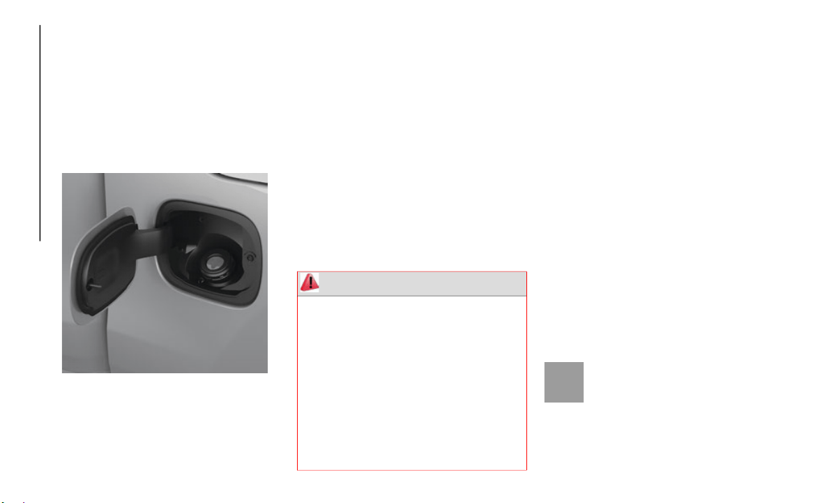
STARTING AND OPERATING
166
1. Put the vehicle in park and switch the
ignition off.
2. Push the center-rear edge of the fuel
filler d
oor (3 o'clock position) and release
to open.
3. Insert the fuel nozzle fully into the filler
pipe, th
e nozzle opens and holds both
flapper doors while refueling.
Fuel Filler
4. When the fuel nozzle “clicks” or shuts
off, the
fuel tank is full.
5. Keep the nozzle in the filler for five
seconds
after nozzle clicks to allow fuel
to drain from the nozzle.
6. Remove the fuel filler nozzle.
7. To clo
se the fuel filler door, push the
center-r
ear edge (3 o’clock position) of
the fuel filler door and then release. The
fuel filler door will latch closed.
NOTE:
In certain cold conditions, ice may prevent
t
he fuel
filler door from opening. If this
occurs, lightly push on the fuel filler door
around the perimeter to break the ice build
up.
Emergency Gas Can Refueling
Most gas cans will not open the flapper
doors.
A fu
nnel is provided to open the flapper
doors to
allow emergency refueling with a gas
can.
1. Retrieve funnel from the jack and jack
tool kit
.
2. Insert funnel into same filler pipe
opening
as the fuel nozzle.
3. Ensure funnel is inserted fully to hold
flapper
doors open.
4. Pour fuel into funnel opening.
5. Remove
funnel from filler pipe, clean off
prior to
putting back in the jack and jack
tool kit.
Materials Added To Fuel
Designated TOP TIER Detergent
Gasoline contains a higher level of
detergent
s to further aide in mini-
mizing engine and fuel system
d
eposits.
When available, the usage of TOP
TIER Detergent gasoline is recommended.
Visit
www.toptiergas.com for a list of TOP
TIER Detergent Gasoline Retailers.
WARNING!
Always place container on the ground
before filling.
Keep the pump nozzle in contact with
the container when you are filling it.
Use only approved containers for flam-
mable liquid.
Do not leave container unattended while
filling.
A static electric charge could cause a
spark and fire hazard.
167
(Continued)
(Continued)
Indiscriminate use of fuel system cleaning
agents should be avoided. Many of these
materials intended for gum and varnish
removal may contain active solvents or
similar ingredients. These can harm fuel
system gasket and diaphragm materials.
TRAILER TOWING
Trailer Towing Weights (Maximum Trailer
Weight Ratings)
NOTE:
For trailer towing information (maximum
trailer we
ight ratings) refer to the following
website addresses:
ramtrucks.com/en/towing_guide/
ramtruck.ca (Canada)
rambodybuilder.com
Towing Requirements
To promote proper break-in of your new
vehicle drivetrain components, the following
guidelines are recommended.
Perform the maintenance listed in the
“Scheduled
Servicing”. Refer to “Scheduled
Servicing” in “Servicing And Maintenance”
for the proper maintenance intervals. When
towing a trailer, never exceed the GAWR or
GCWR ratings.
CAUTION!
Do not tow a trailer at all during the first
500 miles (805 km) the new vehicle is
driven. Th
e engine, axle or other parts
could be damaged.
Then, during the first 500 miles
(805 km) that a trailer is towed, do not
drive over
50 mph (80 km/h) and do not
make start
s at full throttle. This helps
the engine and other parts of the vehicle
wear in at the heavier loads.
WARNING!
Make certain that the load is secured in
the trailer and will not shift during travel.
When trailering cargo that is not fully
secured, dynamic load shifts can occur
that may be difficult for the driver to
control. You could lose control of your
vehicle and have a collision.
When hauling cargo or towing a trailer,
do not overload your vehicle or trailer.
Overloading can cause a loss of control,
poor performance or damage to brakes,
axle, engine, transmission, steering,
suspension, chassis structure or tires.
Safety chains must always be used
between your vehicle and trailer. Always
connect the chains to the hook retainers
of the vehicle hitch. Cross the chains
under the trailer tongue and allow
enough slack for turning corners.
Vehicles with trailers should not be
parked on a grade. When parking, apply
the parking brake on the tow vehicle. Put
the tow vehicle transmission in PARK.
For four-wheel drive vehicles, make sure
the transfer case is not in NEUTRAL.
Always, block or "chock" the trailer
wheels.
GCWR must not be exceeded.
WARNING! (Continued)
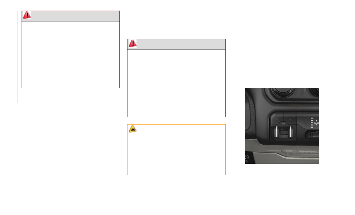
STARTING AND OPERATING
168
Towing Requirements — Trailer Brakes
Do not interconnect the hydraulic brake
system or vacuum system of your vehicle
with that of the trailer. This could cause
inadequate braking and possible personal
injury.
An electronically actuated trailer brake
controller is required when towing a trailer
with electronically actuated brakes. When
towing a trailer equipped with a hydraulic
surge actuated brake system, an elec
-
tronic brake controller is not required.
Trailer brakes are recommended for
trailers over 1,000 lbs (453 kg) and
required for trailers in excess of 2,000 lbs
(907 kg).
Integrated Trailer Brake Module — If
Equipped
Your vehicle may have an Integrated Trailer
Brake Module (ITBM) for Electric and Elec-
tric Over Hydraulic (EOH) trailer brakes.
NOTE:
This module has been designed and verified
w
ith elect
ric trailer brakes and new electric
over hydraulic systems. Some previous EOH
systems may not be compatible with ITBM.
Integrated Trailer Brake Module (ITBM)
Total weight must be distributed between
the tow vehicle and the trailer such that the
following four ratings are not exceeded:
a. GVWR
b. GTW
c. GAW
R
d. To
ngue
weight rating for the trailer
hitch uti
lized.
WARNING! (Continued)
WARNING!
Do not connect trailer brakes to your
vehicle's hydraulic brake lines. It can over-
load your brake system and cause it to fail.
Y
ou might
not have brakes when you need
them and could have an accident.
Towing any trailer will increase your stop-
ping distance. When towing, you should
allow for
additional space between your
vehicle and the vehicle in front of you.
Failure to do so could result in an accident.
CAUTION!
If the trailer weighs more than 1,000 lbs
(453 kg) loaded, it should have its own
brakes and they should be of adequate
capacity. Failure to do this could lead to
accelerated brake lining wear, higher brake
pedal effort, and longer stopping distances.

169
The user interface consists of the following:
Manual Brake Control Lever
Slide the manual brake control lever to the
left to a
ctivate power to the trailer's electric
brakes independent of the tow vehicle's
brakes. If the manual brake control lever is
activated while the brake is also applied, the
greater of the two inputs determines the
power sent to the trailer brakes.
The trailer and the vehicle’s stop lamps will
come on w
hen braking normally with the
vehicle brake pedal. Only the trailer stop
lamps will come on when the manual brake
control lever is applied.
Trailer Brake Status Indicator Light
This light indicates the trailer electrical
connectio
n status.
If no electrical connection is detected after
the ignit
ion is turned on, pushing the GAIN
adjustment button or sliding the manual
brake control lever will display the GAIN
setting for 10 seconds and the “Trailer Brake
Status Indicator Light” will not be displayed.
If a fault is detected in the trailer wiring or
the Integ
rated Trailer Brake Module (ITBM),
the “Trailer Brake Status Indicator Light”
will flash.
GAIN Adjustment Buttons (+/-)
Pushing these buttons will adjust the brake
control p
ower output to the trailer brakes in
0.5
increments. The GAIN setting can be
increased
to a maximum of 10 or decreased
to a minimum of 0 (no trailer braking).
GAIN
The GAIN setting is used to set the trailer
brake con
trol for the specific towing condi-
tion and should be changed as towing condi-
tions change. Changes to towing conditions
i
nclude t
railer load, vehicle load, road condi-
tions and weather.
Adjusting GAIN
NOTE:
This should only be performed in a traffic
f
ree envi
ronment at speeds of approximately
20–25
mph (30–40 km/h).
1. Make sure the trailer brakes are in good
working
condition, functioning normally
and properly adjusted. See your trailer
dealer if necessary.
2. Hook up the trailer and make the elec-
trical c
onnections according to the trailer
manufactu
rer's instructions.
3. When a trailer with electric/EOH brakes
is plugg
ed in, the trailer connected
message should appear in the instrument
cluster display (if the connection is not
recognized by the ITBM, braking func
-
tions will not be available), the GAIN
setting w
ill illuminate and the correct
type of trailer must be selected from the
instrument cluster display options.
4. Push the UP or DOWN button on the
steering
wheel until “TRAILER TOW”
appears on the screen.
5. Push the RIGHT arrow on the steering
wheel to
enter “TRAILER TOW”.
6. Push the UP or DOWN buttons until the
Trailer
Brake Type appears on the screen.
7. Push the RIGHT arrow and then push the
UP or DO
WN buttons until the proper
Trailer Brake Type appears on the screen.
8. In a traffic-free environment, tow the
trailer
on a dry, level surface at a speed
of 20–25
mph (30–40
km/h) and
squeeze the manual brake control lever
completely.

STARTING AND OPERATING
170
9. If the trailer wheels lockup (indicated by
squealing tires), reduce the GAIN
setting; if the trailer wheels turn freely,
increase the GAIN setting.
Repeat steps 8 and 9 until the GAIN setting
is at a point just below trailer wheel lockup.
If towing a heavier trailer, trailer wheel
lockup may not be attainable even with the
maximum GAIN setting of 10.
* The suggested selection depends and may change depending on the customer preferences for braking performance. Condition of the trailer
brakes, dr
iving and road state may also affect the selection.
Display Messages
The trailer brake control interacts with the
i
nstrument
cluster display. Display
messages, along with a single chime, will be
displayed when a malfunction is determined
in the trailer connection, trailer brake
control, or on the trailer. Refer to “Instru
-
ment Cluster Display” in “Getting To Know
Y
our Instr
ument Panel” for further informa-
tion.
NOTE:
An aftermarket controller may be available
for use with trailers with air or elec-
tric-over-hydraulic trailer brake systems.
T
o determi
ne the type of brakes on your
trailer and the availability of controllers,
check with your trailer manufacturer or
dealer.
Removal of the ITBM will cause errors and
it may cause damage to the electrical
system and electronic modules of the
vehicle. See your authorized dealer if an
aftermarket module is to be installed.
Light Electric Heavy Electric Light EOH Heavy EOH
Type of Trailer Brakes Electric Trailer Brakes Electric Trailer Brakes Electric over Hydraulic
Trailer Brakes
Electric over Hydraulic
Trailer Brakes
Load *Under 10,000 lbs *Above 10,000 lbs *Under 10,000 lbs *Above 10,000 lbs
WARNING!
Connecting a trailer that is not compatible
with the ITBM system may result in
reduced or complete loss of trailer braking.
There may be a increase in stopping
distance or trailer instability which could
result in personal injury.
CAUTION!
Connecting a trailer that is not compatible
with the ITBM system may result in
reduced or complete loss of trailer braking.
There may be a increase in stopping
distance or trailer instability which could
result in damage to your vehicle, trailer, or
other property.

171
RECREATIONAL TOWING (BEHIND MOTORHOME, ETC.)
Towing This Vehicle Behind Another Vehicle
NOTE:
When towing your vehicle, always follow
applicable state and provincial laws.
Contact state and provincial Highway
Safety offices for additional details.
Vehicles equipped with Active-Level Four
Corner Air Suspension must be placed in
Transport mode before tying them down
(from the body) on a trailer or flatbed
truck. Refer to “Active-Level Four Corner
Air Suspension – If Equipped” for more
information. If the vehicle cannot be
placed in Transport mode (for example,
engine will not run), tie-downs must be
fastened to the axles (not to the body).
Failure to follow these instructions may
cause fault codes to be set and/or cause
loss of proper tie-down tension.
Recreational Towing — Two-Wheel Drive
Models
DO NOT flat tow this vehicle. Damage to the
drivetrain will result.
Recreational towing (for two-wheel drive
models) i
s allowed ONLY if the rear wheels
are OFF the ground. This may be accom
-
plished using a tow dolly or vehicle trailer. If
using a t
ow dolly, follow this procedure:
NOTE:
If vehicle is equipped with air suspension,
e
nsure th
e vehicle is set to Normal Ride
Height.
1. Properly secure the dolly to the tow
vehicle,
following the dolly manufac-
turer's instructions.
2. D
rive the rear wheels onto the tow dolly.
3. Apply
the parking brake. Place the trans-
mission
in PARK.
Towing Condition
Wheels OFF The
Ground
Two-W
heel Drive
Models
Four-Wheel Drive Models
Flat Tow NONE NOT ALLOWED See Instructions
Transmission in PARK
Transfer case in NEUTRAL (N)
Tow in forward direction
Dolly Tow Front NOT ALLOWED NOT ALLOWED
Rear OK NOT ALLOWED
On Trailer ALL OK OK

STARTING AND OPERATING
172
(Continued)
4. Properly secure the rear wheels to the
dolly, following the dolly manufacturer's
instructions.
5. Turn the ignition OFF.
6. Instal
l a suitable clamping device,
designed
for towing, to secure the front
wheels in the straight position.
Recreational Towing — Four-Wheel Drive
Models
NOTE:
The transfer case must be shifted into
NEUTRAL (
N) for recreational towing. The
transmission must be shifted into PARK for
recreational towing. Refer to the following for
the proper transfer case NEUTRAL (N)
shifting procedure for your vehicle.
Shifting Into NEUTRAL (N)
Use the following procedure to prepare your
vehicle for recreational towing.
CAUTION!
Towing with the rear wheels on the ground
will cause severe transmission damage.
Damage from improper towing is not
covered under the New Vehicle Limited
Warranty.
CAUTION!
DO NOT dolly tow any 4WD vehicle. Towing
with only one set of wheels on the ground
(front or rear) will cause severe transmis
-
sion and/or transfer case damage. Tow with
all four
wheels either ON the ground, or
OFF the ground (using a vehicle trailer).
Tow only in the forward direction. Towing
this vehicle backwards can cause severe
damage to the transfer case.
Before recreational towing, the transfer
case must be in NEUTRAL. To be certain
the transfer case is fully in NEUTRAL,
perform the procedure outlined under
“Shifting Into NEUTRAL”. Internal trans
-
mission damage will result, if the transfer
case is n
ot in NEUTRAL during towing.
The transmission must be in PARK for
recreational towing.
Ensure that the Electric Park Brake is
released, and remains released, while
being towed.
Towing this vehicle in violation of the
above requirements can cause severe
transmission and/or transfer case damage.
Damage from improper towing is not
covered under the New Vehicle Limited
Warranty.
Do not disconnect the rear driveshaft
because fluid will leak from the transfer
case, causing damage to internal parts.
Do not use a bumper-mounted clamp-on
tow bar on your vehicle. The bumper face
bar will be damaged.
WARNING!
You or others could be injured or killed if
you leave the vehicle unattended with the
transfer case in the NEUTRAL (N) position
without first fully engaging the parking
brake. The transfer case NEUTRAL (N)
position disengages both the front and rear
driveshafts from the powertrain and will
allow the vehicle to roll, even if the
transmission is in PARK. The parking
brake should always be applied when the
driver is not in the vehicle.
CAUTION! (Continued)
173
1. Bring the vehicle to a complete stop on
level ground, with the engine running.
Apply the parking brake.
2. Press and hold the brake pedal.
3. Shift
the transmission to NEUTRAL. The
driver's
door must be closed (or the driver's
seat belt buckled) so that the transmission
will remain in NEUTRAL when the brake
pedal is released.
NOTE:
If vehicle is equipped with air suspension,
e
nsure th
e vehicle is set to Normal Ride
Height.
4. Using a ballpoint pen or similar object,
push and
hold the recessed transfer case
NEUTRAL (N) button (at the center of the
transfer case switches). The NEUTRAL (N)
indicator light will illuminate, and remain
lit, when the shift to NEUTRAL (N) is
complete. After the shift is completed and
the NEUTRAL (N) light stays on, release
the NEUTRAL (N) button.
5. Release the parking brake.
6. Shift
the transmission into REVERSE.
7. Releas
e the brake pedal for five seconds
and ensu
re that there is no vehicle move-
ment.
8. R
epeat steps 6 and 7 with the transmis-
sion in
DRIVE.
9. Shift the transmission to NEUTRAL.
Apply th
e parking brake. Turn OFF the
engine. For vehicles with Keyless
Enter-N-Go, push and hold the ENGINE
START/STOP button until the engine
shuts off. The transmission will automat
-
ically select PARK when the engine is
t
urned of
f.
10.Turn the ignition to the OFF mode.
11.Attac
h the vehicle to the tow vehicle
using a
suitable tow bar.
12.Turn the ignition to the ON/RUN mode,
but do n
ot start the engine.
13.Release the parking brake.
14.Turn
the ignition OFF.
NOTE:
Steps 2 and 3 are requirements that must
be met before pushing the NEUTRAL (N)
button, and must continue to be met until
the shift has been completed. If any of
these requirements are not met before
pushing the NEUTRAL (N) button or are
no longer met during the shift, the
NEUTRAL (N) indicator light will flash
continuously until all requirements are
met or until the NEUTRAL (N) button is
released.
The ignition must be in the ON/RUN mode
for a shift to take place and for the posi-
tion indicator lights to be operable. If the
i
gnition
is not in the ON/RUN mode, the
shift will not take place and no position
indicator lights will be on or flashing.
A flashing NEUTRAL (N) position indi-
cator light indicates that shift require-
ments have not been met.
If the vehicle is equipped with air suspen-
sion, the engine should be started and left
running f
or a minimum of 60 seconds
(with all the doors closed) at least once
every 24 hours. This process allows the air
suspension to adjust the vehicle’s ride
height to compensate for temperature
effects.
CAUTION!
It is necessary to follow these steps to be
certain that the transfer case is fully in
NEUTRAL (N) before recreational towing
to prevent damage to internal parts.

STARTING AND OPERATING
174
Shifting Out Of NEUTRAL (N)
Use the following procedure to prepare your
vehicle for normal usage:
1. Bring the vehicle to a complete stop,
leaving
it connected to the tow vehicle.
2. Press and hold the brake pedal.
3. Start
the engine. Apply the parking
brake. S
hift the transmission into
NEUTRAL.
4. Using a ballpoint pen or similar object,
push and
hold the recessed transfer case
NEUTRAL (N) button (at the center of
the transfer case switches).
5. When the NEUTRAL (N) indicator light
turns of
f, release the NEUTRAL (N)
button.
6. Turn the engine OFF. The transmission
will aut
omatically select PARK when the
engine is turned off.
7. Release the brake pedal.
8. Discon
nect vehicle from the tow vehicle.
9. Press
and hold the brake pedal.
10.Start
the engine.
11.Relea
se the parking brake.
12.Shift
the transmission into DRIVE,
release
the brake pedal, and check that
the vehicle operates normally.
NOTE:
Steps 2 and 3 are requirements that must
be met before pushing the button to shift
out of NEUTRAL (N), and must continue
to be met until the shift has been
completed. If any of these requirements
are not met before pushing the button or
are no longer met during the shift, the
NEUTRAL (N) indicator light will flash
continuously until all requirements are
met or until the button is released.
The ignition must be in the ON/RUN mode
for a shift to take place and for the posi-
tion indicator lights to be operable. If the
i
gnition
is not in the ON/RUN mode, the
shift will not take place and no position
indicator lights will be on or flashing.
A flashing NEUTRAL (N) position indi-
cator light indicates that shift require-
ments have not been met.

175
HAZARD WARNING
FLASHERS
The Hazard Warning switch is
located on the upper switch bank
just below
the radio.
NOTE:
If your vehicle is equipped with a 12–inch
U
connect d
isplay, the Hazard Warning
switch is located above the display.
Push the switch to turn on the Hazard
Warning fl
asher. When the switch is acti-
vated, all directional turn signals will flash
o
n and off
to warn oncoming traffic of an
emergency. Push the switch a second time to
turn off the Hazard Warning flashers.
This is an emergency warning system and it
should not
be used when the vehicle is in
motion. Use it when your vehicle is disabled
and it is creating a safety hazard for other
motorists.
When you must leave the vehicle to seek
assistance
, the Hazard Warning flashers will
continue to operate even though the ignition
is placed in the OFF position.
NOTE:
With extended use the Hazard Warning
flashers m
ay wear down your battery.
ASSIST AND SOS SYSTEM —
IF EQUIPPED
Assist And SOS Buttons
If equipped, the overhead console contains
an ASSIST
and a SOS button.
NOTE:
Your vehicle may be transmitting data as
authorized by the subscriber.
The SOS and ASSIST buttons will only
function if you are connected to an oper-
able LTE (voice/data) or 4G (data)
n
etwork. O
ther Uconnect services will only
be operable if your SiriusXM Guardian
service is active and you are connected to
an operable LTE (voice/data) or 4G (data)
network.
1 — ASSIST Button
2 — SOS Button
WARNING!
ALWAYS obey traffic laws and pay
attention to the road. ALWAYS drive safely
with your hands on the steering wheel. You
have full responsibility and assume all
risks related to the use of the features and
applications in this vehicle. Only use the
features and applications when it is safe to
do so. Failure to do so may result in an
accident involving serious injury or death.

IN CASE OF EMERGENCY
176
ASSIST Call
The ASSIST Button is used to automatically
connect yo
u to any one of the following
support centers:
Roadside Assistance – If you get a flat tire,
or need a tow, just push the ASSIST
button and you’ll be connected to
someone who can help. Roadside Assis
-
tance will know what vehicle you’re driving
and its lo
cation. Additional fees may apply
for roadside assistance.
SiriusXM Guardian Customer Care –
In-vehicle support for SiriusXM Guardian.
Vehicle Customer Care – Total support for
all other vehicle issues.
SOS Call
1. P
ush the SOS Call button on the over-
head cons
ole.
NOTE:
In case the SOS Call button is pushed in
e
rror, the
re will be a ten second delay before
the SOS Call system initiates a call to a SOS
operator. To cancel the SOS Call connection,
push the SOS call button on the overhead
console or press the cancellation button on
the Device Screen. Termination of the SOS
Call will turn off the green LED light on the
overhead console.
2. The LED light located between the
ASSIST an
d SOS buttons on the over-
head console will turn green once a
c
onnection
to a SOS operator has been
made.
3. Once a connection between the vehicle
and a SOS
operator is made, the SOS
Call system may transmit the following
important vehicle information to a SOS
operator:
Indication that the occupant placed a
SOS Call.
The vehicle brand.
The last known GPS coordinates of the
vehicle.
4. You should be able to speak with the SOS
operator
through the vehicle audio
system to determine if additional help is
needed.
NOTE:
Your vehicle may be transmitting data as
authorized by the subscriber.
Once a connection is made between the
vehicle’s SOS Call system and the SOS
operator, the SOS operator may be able
to open a voice connection with the
vehicle to determine if additional help is
needed. Once the SOS operator opens a
voice connection with the vehicle’s SOS
Call system, the operator should be able
to speak with you or other vehicle occu
-
pants and hear sounds occurring in the
vehicle. T
he vehicle’s SOS Call system
will attempt to remain connected with
the SOS operator until the SOS operator
terminates the connection.
WARNING!
ALWAYS obey traffic laws and pay
attention to the road. ALWAYS drive safely
with your hands on the steering wheel. You
have full responsibility and assume all
risks related to the use of the features and
applications in this vehicle. Only use the
features and applications when it is safe to
do so. Failure to do so may result in an
accident involving serious injury or death.
177
(Continued)
(Continued)
5. The SOS operator may attempt to contact
appropriate emergency responders and
provide them with important vehicle
information and GPS coordinates.
SOS Call System Limitations
Vehicles sold in Mexico D
O NOT hav
e SOS
Call system capabilities.
SOS or other emergency line operators in
Mexico ma
y not answer or respond to SOS
system calls.
If the SOS Call system detects a malfunc-
tion, any of the following may occur at the
time the
malfunction is detected, and at the
beginning of each ignition cycle:
The overhead console light located
between the ASSIST and SOS buttons will
continuously be illuminated red.
The Device Screen will display the
following message: “Vehicle device
requires service. Please contact your
dealer.”
An In-Vehicle Audio message will state
“Vehicle device requires service. Please
contact your dealer.”
WARNING!
If anyone in the vehicle could be in
danger (e.g., fire or smoke is visible,
dangerous road conditions or location),
do not wait for voice contact from an
Emergency Services Agent. All occu
-
pants should exit the vehicle immedi-
ately and move to a safe location.
Never place anything on or near the
vehicle’s operable network and GPS
antennas. You could prevent operable
network and GPS signal reception, which
can prevent your vehicle from placing an
emergency call. An operable network
and GPS signal reception is required for
the SOS Call system to function prop
-
erly.
The SOS Call system is embedded into
the vehicle’s electrical system. Do not
add aftermarket electrical equipment to
the vehicle’s electrical system. This may
prevent your vehicle from sending a
signal to initiate an emergency call. To
avoid interference that can cause the
SOS Call system to fail, never add after
-
market equipment (e.g., two-way mobile
radio, CB
radio, data recorder, etc.) to
your vehicle’s electrical system or modify
the antennas on your vehicle. IF YOUR
VEHICLE LOSES BATTERY POWER FOR
ANY REASON (INCLUDING DURING OR
AFTER AN ACCIDENT), THE UCON
-
NECT FEATURES, APPS AND
SERVICES,
AMONG OTHERS, WILL
NOT OPERATE.
Modifications to any part of the SOS Call
system could cause the air bag system to
fail when you need it. You could be
injured if the air bag system is not there
to help protect you.
WARNING! (Continued)
WARNING!
Ignoring the overhead console light
could mean you will not have SOS Call
services. If the overhead console light is
illuminated, have your authorized dealer
service the SOS Call system immedi
-
ately.

IN CASE OF EMERGENCY
178
Even if the SOS Call system is fully func-
tional, factors beyond FCA US LLC’s control
may preve
nt or stop the SOS Call system
operation. These include, but are not limited
to, the following factors:
Delayed accessories mode is active.
The ignition is in the OFF position.
The vehicle’s electrical systems are not
intact.
The SOS Call system software and/or hard-
ware are damaged during a crash.
The vehicle battery loses power or
becomes disconnected during a vehicle
crash.
LTE (voice/data) or 4G (data) network and/
or Global Positioning Satellite signals are
unavailable or obstructed.
Equipment malfunction at the SOS oper-
ator facility.
Operator error by the SOS operator.
LTE (voice/data) or 4G (data) network
congestion.
Weather.
Buildings, structures, geographic terrain,
or tunnels.
NOTE:
Your vehicle may be transmitting data as
authorized by the subscriber.
Never place anything on or near the
vehicle’s LTE (voice/data) or 4G (data) and
GPS antennas. You could prevent LTE
(voice/data) or 4G (data) and GPS signal
reception, which can prevent your vehicle
from placing an emergency call. An oper
-
able LTE (voice/data) or 4G (data) network
c
onnectio
n and a GPS signal is required
for the SOS Call system to function prop
-
erly.
General Information
This device complies with Part 15 of the FCC
Rules. Op
eration is subject to the following
two conditions: (1) This device may not
cause harmful interference, and (2) this
device must accept any interference
received, including interference that may
cause undesired operation.
NOTE:
Changes or modifications not expressly
approved
by the party responsible for compli-
ance could void the user's authority to
o
perate t
he equipment.
The Occupant Restraint Control module
turns on the air bag Warning Light on the
instrument panel if a malfunction in any
part of the system is detected. If the Air
Bag Warning Light is illuminated, have
your authorized dealer service the Occu
-
pant Restraint Control system immedi-
ately.
WARNING! (Continued)
WARNING!
ALWAYS obey traffic laws and pay
attention to the road. ALWAYS drive safely
with your hands on the steering wheel. You
have full responsibility and assume all
risks related to the use of the features and
applications in this vehicle. Only use the
features and applications when it is safe to
do so. Failure to do so may result in an
accident involving serious injury or death.

179
BULB REPLACEMENT
Replacement Bulbs
All of the inside bulbs are brass or glass-wedge base. Aluminum base bulbs are not approved.
Interior Bulbs
Bulb Number
Overhead Console Lamps TS 212–9
Dome Lamp 7679
For lighted switches, see your authorized dealer for replacement instructions.
Exterior Bulbs
Bulb Number
Low Beam (Halogen Reflector Headlamp) H11LL
High Beam (Halogen Reflector Headlamp) 9005LL
Low & High Beam (LED Reflector Headlamp) LED (Serviced At An Authorized Dealer)
Low & High Beam (LED Projector Headlamp) LED (Serviced At An Authorized Dealer)
Turn Signal / Front Position (Halogen Reflector Headlamp) 7444NA
Turn Signal / Front Position (LED Headlamps) LED (Serviced at authorized dealer)
Front Side Marker (Halogen Reflector Headlamp) W5W
Front Side Marker (LED Headlamps) LED (Serviced At An Authorized Dealer)
Front Fog Lamps (Halogen Reflector Headlamp) H11LL
Front Fog Lamps (LED Headlamps) LED (Serviced At An Authorized Dealer)
Side Indicators (Front And Side View Mirror) LED (Serviced at authorized dealer)
Base Rear Tail/Turn and Stop Lamp 3157K
IN CASE OF EMERGENCY
180
(Continued)
FUSES
Power Distribution Center
The Power Distribution Center is located in
the engine compartment near the battery.
This center contains cartridge fuses, micro
fuses, relays, and circuit breakers. A descrip
-
tion of each fuse and component may be
stamped o
n the inside cover, otherwise the
cavity number of each fuse is stamped on the
inside cover that corresponds to the
following chart.
Premium Rear Tail/Turn and Stop Lamp LED (Serviced At An Authorized Dealer)
Premium Backup Lamp 7440/W21W
Center High Mounted Stop Lamp (CHMSL) 921
Backup Lamp 921
Rear License Plate Lamp 194
Exterior Bulbs
Bulb Number
WARNING!
When replacing a blown fuse, always use
an appropriate replacement fuse with
the same amp rating as the original fuse.
Never replace a fuse with another fuse of
higher amp rating. Never replace a blown
fuse with metal wires or any other mate
-
rial. Do not place a fuse inside a circuit
b
reaker c
avity or vice versa. Failure to
use proper fuses may result in serious
personal injury, fire and/or property
damage.
Before replacing a fuse, make sure that
the ignition is off and that all the other
services are switched off and/or disen
-
gaged.
If the replaced fuse blows again, contact
an authorized dealer.
If a general protection fuse for safety
systems (air bag system, braking
system), power unit systems (engine
system, transmission system) or steering
system blows, contact an authorized
dealer.
WARNING! (Continued)

181
Cavity Cartridge Fuse Micro Fuse Description
F01 – 25 Amp Clear Fuel Pump Motor
F02 – – Spare
F03 – 5 Amp Tan MGU – If Equipped
F04 – – Spare
F05 – – Spare
F06 – – Spare
F07 – – Spare
F08 20 Amp Blue – Trailer Tow Backup
F09 – 20 Amp Yellow Trailer Stop / Turn Lamp Left
F10 – 20 Amp Yellow Trailer Stop / Turn Lamp Right
F11 – – Spare
F12 20 Amp Blue – Trailer Tow Park Lamp
F13 – – Spare
F14 – 10 Amp Red AC Clutch
F15 – 5 Amp Tan IBS
F16 – – Spare
F17 – 20 Amp Yellow Air Suspension
F18 – 15 Amp Blue AGS / Rear Axle Cooling Valve / Active Air Dam
F19 – – Spare
F20 – 20 Amp Yellow Adjustable Pedals
F21 – – Spare
F22 50 Amp Red – I Air Module
F23 – – Spare
F24 – 20 Amp Yellow TCM SBW
F25 50 Amp Red – Power Side Step

IN CASE OF EMERGENCY
182
F26 50 Amp Red – ESP Module
F27 30 Amp Pink – Front Wiper
F28 – 10 Amp Red PCM / ECM
F29 40 Amp Green – ESP Module
F30 – – Spare
F31 – – Spare
F32 20 Amp Blue – ECM / PCM
F33 30 Amp Pink – Brake Vacuum Pump
F34 – – Spare
F35 – 10 Amp Red PCM / ECM / Power Pack Unit (PPU) Motor Generator
U
nit (MGU
) Wake Up / EPS / Active Tuned Mass
Module (ATMM) / ESP
F36 – – Spare
F37 – 5 Amp Tan R / S Output to iPDC
F38 – 10 Amp Red DTCM / Active CL TEMP VLV
F39 – – Spare
F40 40 Amp Green – Starter
F41 – 10 Amp Red IRCAM Heaters
F42 – – Spare
F43 – 20 Amp Yellow MGU Coolant Pump – If Equipped
F44 – – Spare
F45 – – Spare
F46 30 Amp Pink – Fuel Heater – If Equipped
F47 30 Amp Pink – Rear Defroster
F48 – – Spare
Cavity Cartridge Fuse Micro Fuse Description
183
(Continued)
Internal Power Distribution Center
The Power Distribution Center is located under
the drivers side instrument panel. This center
contains cartridge fuses, micro fuses, relays,
and circuit breakers. A description of each fuse
and component may be stamped on the inside
cover, otherwise the cavity number of each fuse
is stamped on the inside cover that corresponds
to the following chart.
F49 30 Amp Pink – Htr Ctrl – If Equipped (Diesel Only)
F50 – – Spare
F51 – – Spare
F52 – – Spare
F53 – 10 Amp Red Supply / Purging Pump – If Equipped
F54 – 15 Amp Blue PCM – If Equipped
F55 – 15 Amp Blue Right HID Headlamp
F56 – – Spare
F57 – 20 Amp Yellow Horn
F58 – – Spare
F59 – 25 Amp Clear Injectors / IGN Coil / Glow Plug Module
F60 – 20 Amp Yellow ECM / PCM / ACT Short Running Valve
F61 – 15 Amp Blue Left HID Headlamp
F62 60 Amp Blue – Glow Plug – If Equipped
F63 20 Amp Blue – NOx Sensor #1/#2 – If Equipped
F64 – 10 Amp Red PM Sensor – If Equipped
Cavity Cartridge Fuse Micro Fuse Description
CAUTION!
When installing the power distribution
center cover, it is important to ensure the
cover is properly positioned and fully
latched. Failure to do so may allow water to
get into the power distribution center and
possibly result in an electrical system
failure.
When replacing a blown fuse, it is
important to use only a fuse having the
correct amperage rating. The use of a fuse
with a rating other than indicated may
result in a dangerous electrical system
overload. If a properly rated fuse continues
to blow, it indicates a problem in the
circuit that must be corrected.
CAUTION! (Continued)

IN CASE OF EMERGENCY
184
Cavity Cartridge Fuse Micro Fuse Description
F01 30 Amp Pink – Trailer Tow Receptacle
F02 – – Spare
F03 – 20 Amp Yellow Module Seat Heater Front (Pass)
F04 – – Spare
F05 – 20 Amp Yellow Module PPU Cooling Fan
F06 40 Amp Green – Mod CBC 4 Exterior Light 2
F07 40 Amp Green – Mod CBC 3 PWR Locks
F08 – – Spare
F09 – – Spare
F10 40 Amp Green – HVAC Blower Motor
F11 – 5 Amp Tan Output to Underhood Power Distribution Center
(
UPDC) Ru
n Coil
F12 – 25 Amp Clear Mod Audio Amplifier / Active Noise Cancellation / SW
Inverter
F1
3 – 20 Amp Yellow Mod Seat Heater Front (Driver)
F14 – 15 Amp Blue Mod Seat Heater Front (Steering Wheel)
F15 – – Spare
F16 – – Spare
F17 – – Spare
F18 30 Amp Pink – Motor Sunshade Sunroof
F19 – – Spare
F20 – 20 Amp Yellow Comfort Rear Seat Module (CRSM) (Heat Rear RT)
F21 – – Spare
F22 – – Spare
F23 – – Spare

185
F24 – 15 Amp Blue Mod RF Hub / Mod Ignition / Mod Cluster
F25 40 Amp Green – Mod Integrated Trailer Brake
F26 – 15 Amp Blue Mod Cluster CCN / Mod Cyber Security
F27 – 5 Amp Tan Mod Cluster CCN / Mod SGW
F28 – 10 Amp Red Mod ORC
F29 – 20 Amp Yellow Mod CRSM (Heat Rear LT)
F30 30 Amp Pink – Mod DTCM / Mod Tailgate
F31 30 Amp Pink – Mod CBC 1 Interior Light
F32 – – Spare / Sunshade
F33 – 10 Amp Red Assy Overhead Console / Switch 911 / Switch Assist /
S
unshade
F3
4 – 15 Amp Blue Frt & RR Ventilated Seat Motor
F35 – 10 Amp Red Mod Inverter / Mtr Sunshade Sunroof / Mtr Dual
S
unroof
F36 4
0 Amp Green – Mod CBC 2 Exterior Light 1
F37 – – Spare
F38 – – Spare
F39 – – Spare
F40 – – Spare
F41 A&B – 15 Amp Blue Lumbar Support & Pass SW / Mod Cluster CCN
F42 A&B – 10 Amp Red Mod Transfer Case Switch Module (TCSM) / SBW /
E
lectric
Park Brake SW / Overhead Console (OHC) SW
/ E-Call / Bank 3 SW / Seat LT & RT Vent
F43 A&B – 10 Amp Red Port Diagnostics / Mod CD / Front & Rear USB
F44 – 20 Amp Yellow Radio / DCSD / Telematics Box Mod
Cavity Cartridge Fuse Micro Fuse Description

IN CASE OF EMERGENCY
186
F45 30 Amp Pink – Mod Door MUX Driver
F46 30 Amp Pink – Mod Door MUX Passenger
F47 – – Spare
F48 A&B 10 Amp Red – Rear View Mirror / Humidity Rain And Light Sensor
(
HRLS) /
SW Window Passenger / Rear USB / Wireless
Charging Pad Mod
F49 – 15 Amp Blue Mod CVPM / SNSR Blind Spot / HDLP Adaptive Front
Lighting
Sensor (AFLS)
F50 A&B – 10 Amp Red Battery PACK Control Mod
F51 A&B – – Spare
F52 20 Amp Blue – Direct Battery Feed
F53 – 15 Amp Blue Mod ICS Switch / Mod HVAC CTRL / Sw Bank Upper /
S
w EPB /
Mod Control Steering
F54 A&B – 20 Amp Yellow Power Outlet Center Seat
F55 25 Amp White – Upfitter
F56 30 Amp Pink – Mod Network Interface
F57 20 Amp Blue – Direct Battery Feed
F58 20 Amp Blue – Direct Battery Feed
F60 50 Amp Red – Mod Inverter
F61 – – Spare
F62 A&B – 10 Amp Red ITBM / Mod Occupant Class / Mod IAIR Suspension /
M
od HVAC
Snsr Incar Temp / Rear Coolant Temp /
PTS / Mod IRCM
F63 – – Spare
Cavity Cartridge Fuse Micro Fuse Description
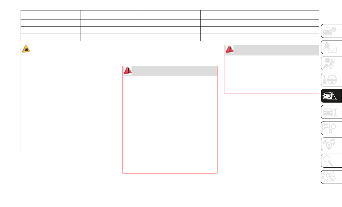
187
(Continued)
JACKING AND TIRE
CHANGING
NOTE:
If your vehicle is equipped with an air
suspensio
n system, there is a feature which
allows the automatic leveling to be disabled
to assist with changing a tire.
This feature can be activated through the
Uconnect
system.
Refer to “Uconnect Settings” in “Multi-
media” in the Owner’s Manual for further
i
nformati
on.
Jack Location
The jack and jack tools are stored under the
front passenger seat.
F64 – – Spare
F65 – 10 Amp Red Mod ORC
F66 10 Amp Red Run - Accessory Feed
Cavity Cartridge Fuse Micro Fuse Description
CAUTION!
When installing the power distribution
center cover, it is important to ensure
the cover is properly positioned and fully
latched. Failure to do so may allow water
to get into the power distribution center
and possibly result in an electrical
system failure.
When replacing a blown fuse, it is
important to use only a fuse having the
correct amperage rating. The use of a
fuse with a rating other than indicated
may result in a dangerous electrical
system overload. If a properly rated fuse
continues to blow, it indicates a problem
in the circuit that must be corrected.
WARNING!
Do not attempt to change a tire on the
side of the vehicle close to moving
traffic. Pull far enough off the road to
avoid the danger of being hit when oper
-
ating the jack or changing the wheel.
Being under a jacked-up vehicle is
dangerous. The vehicle could slip off the
jack and fall on you. You could be
crushed. Never put any part of your body
under a vehicle that is on a jack. If you
need to get under a raised vehicle, take
it to a service center where it can be
raised on a lift.
Never start or run the engine while the
vehicle is on a jack.
The jack is designed to be used as a tool
for changing tires only. The jack should
not be used to lift the vehicle for service
purposes. The vehicle should be jacked
on a firm level surface only. Avoid ice or
slippery areas.
WARNING! (Continued)
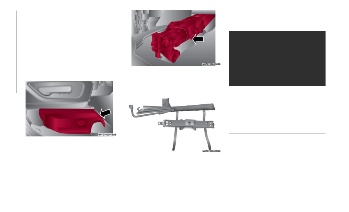
IN CASE OF EMERGENCY
188
Removal Of Jack And Tools
To access the jack and jack tools, you must
remove the plastic access cover located on
the side of the front passenger’s seat. To
remove the cover, pull the front part of the
cover (closest to the front of the seat) toward
you to release a locking tab. Once the front
of the cover is loose, slide the cover toward
the front of the seat until it is free from the
seat frame.
Pull Jack Access Cover From Front
Remove the jack and tools by turning the
w
ing bolt
counterclockwise, remove the wing
bolt and then slide the assembly out from
under the seat.
Jack And Tools
Release the tool bag straps from the jack and
remove to
ols from bag.
Jack And Tool Bag
There are two ways to assemble the tools:
Assembled For Spare Tire Lowering/Raising
Assembled For Spare Tire Lowering/Raising
NOTE:
If the tailgate is lowered, the jack extension
with hook
can be added to this assembly to
enable lowering of the spare tire without
having to raise the tailgate.
1 — Lug Wrench
2 — Long Extension Without Spring Clip 2
3 — Long Extension With Spring Clip 3
4 — Long Extension With Spring Clip 4
5 — Short Extension 5
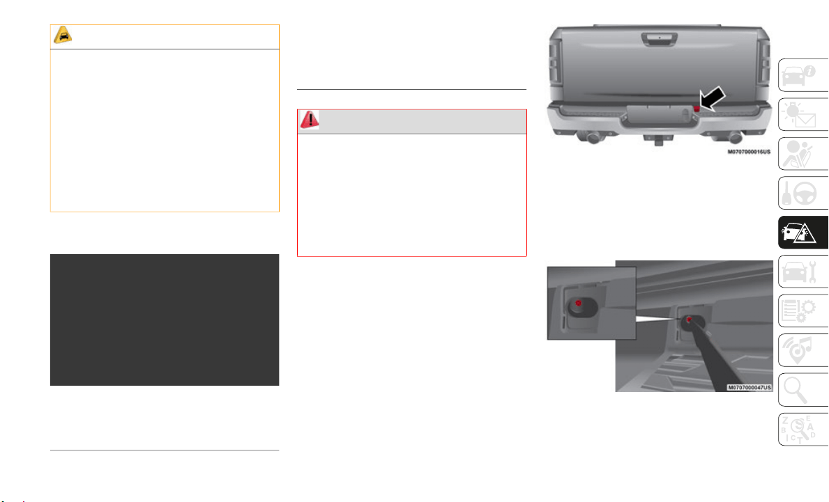
189
Assembled For Jack Operation
Assembled For Jack Operation
Removing The Spare Tire
1. Remove the spare tire before attempting
to jack up the truck. Attach the lug
wrench to the extension tubes with the
curved angle facing away from the
vehicle.
2. Remove the protective cover over the
access h
ole for the winch mechanism by
sliding the cover upward.
Access Hole Cover Location
3. Insert the extension tube through the
access h
ole between the lower tailgate
and the top of the bumper and into the
winch mechanism tube.
Winch Mechanism Tube
CAUTION!
The lug wrench can only be attached to
extension 2.
When attaching the tool to the winch
mechanism be sure the large flared end
opening on extension 4 is positioned
correctly over the winch mechanism
adjusting nut.
Damage to the lug wrench, extensions
and winch mechanism may occur from
improper tool assembly.
1 — Lug Wrench
2 — Long Extension 2
3 — Long Extension 3
4 — Long Extension 4
5 — Short Extension 5
6 — Extension With Hook
WARNING!
After using the jack and tools, always
reinstall them in the original carrier and
location. While driving you may experience
abrupt stopping, rapid acceleration or
sharp turns. A loose jack, tools, bracket or
other objects in the vehicle may move
around with force, resulting in serious
injury.
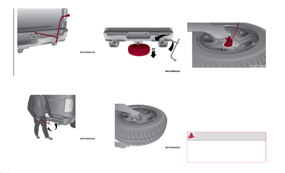
IN CASE OF EMERGENCY
190
Inserting The Extension Tubes Into The Access
Hole
4. Rotate the lug wrench handle counter-
clockwis
e until the spare tire is on the
ground wi
th enough cable slack to allow
you to pull it out from under the vehicle.
Rotating The Lug Wrench Handle
5. P
ull the spare tire out from under the
vehicle
to gain access to the spare tire
retainer.
Pulling The Spare Tire Out
6. L
ift the spare tire with one hand to give
clearanc
e to tilt the retainer at the end of
the cable.
Gaining Access To The Retainer
7. Pull the retainer through the center of the
wheel.
Pul
ling The Retainer Through The Center Of The
Wheel
NOTE:
The winch mechanism is designed for use
with the
extension tubes only. Use of an air
wrench or other power tools is not recom
-
mended and can damage the winch.
Preparations For Jacking
1. Park on a firm, level surface. Avoid ice or
slippery areas.
WARNING!
Do not attempt to change a tire on the side
of the vehicle close to moving traffic. Pull far
enough off the road to avoid being hit when
operating the jack or changing the wheel.
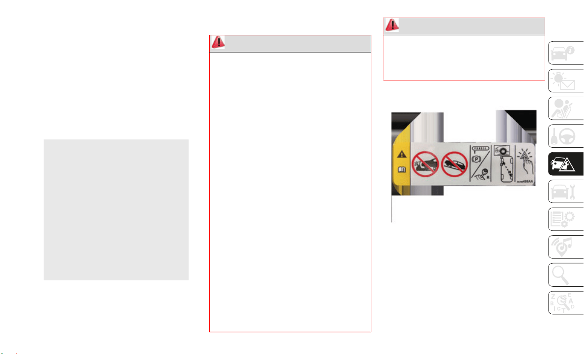
191
(Continued)
2. Turn on the Hazard Warning flasher.
3. Apply the parking brake.
4. Shift
the transmission into Park (P).
5. Turn t
he ignition OFF.
6. Block
both the front and rear of the wheel
diagonal
ly opposite the jacking position.
For example, if the right front wheel is
being changed, block the left rear wheel.
Wheel Blocked
NOTE:
Passengers should not remain in the vehicle
w
hen the
vehicle is being jacked.
Jacking Instructions
Jack Warning Label
WARNING!
Carefully follow these tire changing warnings
to help prevent personal injury or damage to
your vehicle:
Always park on a firm, level surface as far
from the edge of the roadway as possible
before raising the vehicle.
Turn on the Hazard Warning flasher.
Block the wheel diagonally opposite the
wheel to be raised.
Apply the parking brake firmly and set the
transmission in PARK.
Never start or run the engine with the
vehicle on a jack.
Do not let anyone sit in the vehicle when it
is on a jack.
Do not get under the vehicle when it is on
a jack. If you need to get under a raised
vehicle, take it to a service center where it
can be raised on a lift.
Only use the jack in the positions indicated
and for lifting this vehicle during a tire
change.
If working on or near a roadway, be
extremely careful of motor traffic.
To assure that spare tires, flat or
inflated, are securely stowed, spares
must be stowed with the valve stem
facing the ground.
WARNING! (Continued)
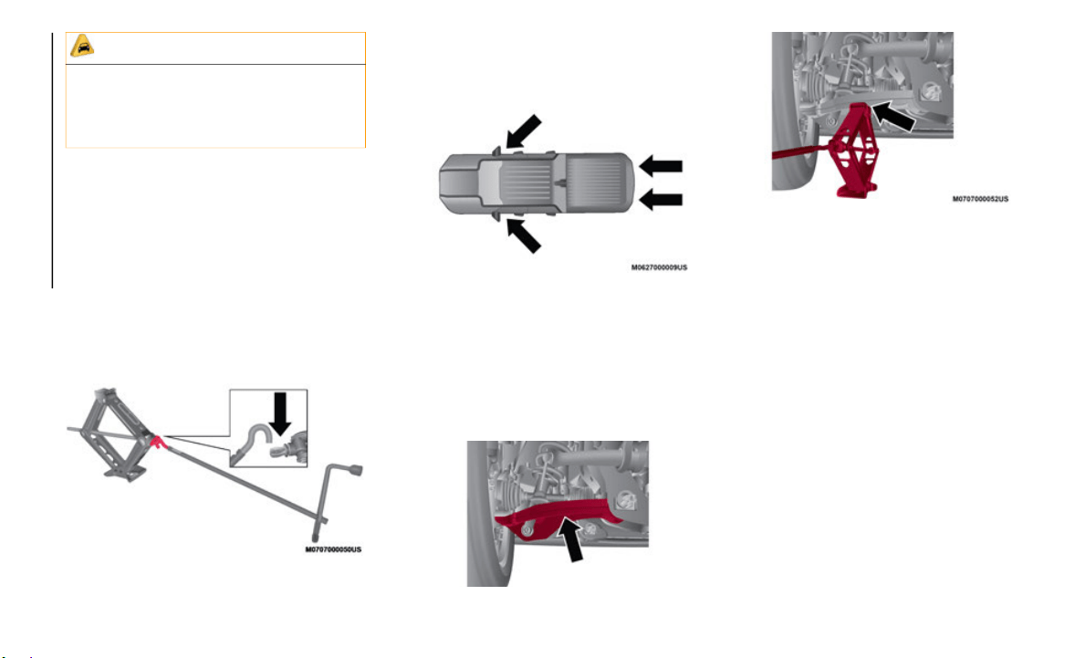
IN CASE OF EMERGENCY
192
1. Remove the spare wheel, jack, and tools
from storage.
2. Using the lug wrench, loosen, but do not
remove,
the wheel nuts by turning them
counterclockwise one turn while the
wheel is still on the ground.
3. Assemble the jack and jacking tools.
Connect
the jack handle driver to the
extension, then to the lug wrench.
Assembled Jack And Tools
4. P
lacement of the jack is critical.
NOTE:
Keep
the jack and tools aligned with raising the
v
ehicle.
Ja
ck / Extensions Placement
Front Jacking Location
When changing a front wheel, place the
scissor j
ack under the rear portion of the
lower control arm as shown. Access the front
jacking location from behind the front tire.
Front Lifting Point
Front Jacking Location
Rear Jacking Location
Operate the jack using the extension with
j
ack hook
and the lug wrench. The exten-
sion tubes may be used but is not re-
quired.
When changing a rear wheel, assemble
t
he exten
sion with jack hook to the jack
and connect the extension tubes. Access
the rear jacking location from behind the
rear tire. Place the jack under the Jack
Lifting Point located on the rear axle low
-
er control arm bracket. Then locate the
s
lot in t
he jack lift plate onto the rear axle
Jack Lifting Point. Attach the extension
with jack hook extending to the rear of
the vehicle.
CAUTION!
Do not attempt to raise the vehicle by
jacking on locations other than those
indicated in the Jacking Instructions for
this vehicle.
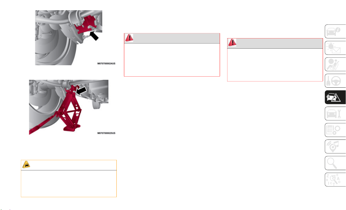
193
Rear Lifting Point
Rear Jacking Location
5. Connect the long extensions and lug wrench.
6. By rot
ating the lug wrench clockwise,
raise th
e vehicle until the wheel just
clears the surface.
7. Remove the lug nuts and pull the wheel
off. Ins
tall the spare wheel and lug nuts
with the cone shaped end of the lug nuts
toward the wheel. Hand tighten the lug
nuts with vehicle lifted. To avoid the risk
of forcing the vehicle off the jack, do not
fully tighten the lug nuts until the vehicle
has been lowered.
8. Lower vehicle to ground, finish tight-
ening th
e lug nuts. Push down on the
wrench wh
ile at the end of the handle for
increased leverage. Tighten the lug nuts
in a star pattern until each nut has been
tightened twice.
NOTE:
For the correct lug nut torque refer to
“Torque S
pecifications” in “Technical Spec-
ifications.”If in dou
bt about the correct
tightness, have them checked with a torque
wrench by an authorized dealer or service
station.
9. If your vehicle is equipped with a wheel
center c
ap, install the cap and remove
the wheel blocks. Do not install chrome
or aluminum wheel center caps on the
spare wheel. This may result in cap
damage.
10.Lower the jack to its fully closed position.
Stow the
replaced tire, jack, and tools as
previously described.
11.Adjust the tire pressure when possible.
CAUTION!
Before raising the wheel off the ground,
make sure that the jack will not damage
surrounding truck parts and adjust the
jack position as required.
WARNING!
Raising the vehicle higher than necessary
can make the vehicle less stable. It could
slip off the jack and hurt someone near it.
Raise the vehicle only enough to remove
the tire.
WARNING!
A loose tire or jack thrown forward in a
collision or hard stop, could endanger the
occupants of the vehicle. Always stow the
jack parts and the spare tire in the places
provided.
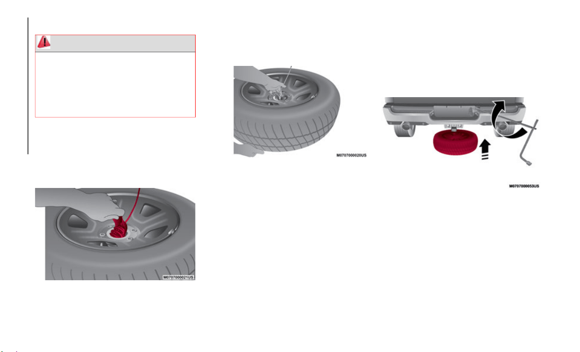
IN CASE OF EMERGENCY
194
To Stow The Flat Or Spare
1. Turn the wheel so that the valve stem is
facing upward and toward the rear of the
vehicle for convenience in checking the
spare tire inflation. Slide the wheel
retainer through the center of the wheel.
Reinstalling The Retainer
2. Lift the spare tire with one hand to give
clearanc
e to tilt the retainer at the end of
the cable and position it properly across
the wheel opening.
Pushing The Retainer Through The Center Of
The Wheel And Positioning It
3. Attach the lug wrench to the extension
tubes with the curved angle facing away
from the vehicle. Insert the extension
tubes through the access hole between
the lower tailgate and the top of the
bumper and into the winch mechanism
tube.
Lug Wrench And Extension Tubes Assembled
And In Position
WARNING!
A loose tire or jack thrown forward in a
collision or hard stop could endanger the
occupants of the vehicle. Always stow the
jack parts and the spare tire in the places
provided. Have the deflated (flat) tire
repaired or replaced immediately.
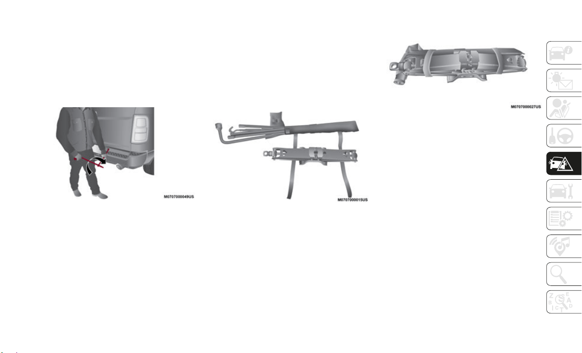
195
4. Rotate the lug wrench handle clockwise
until the wheel is drawn into place
against the underside of the vehicle.
Continue to rotate until you feel the
winch mechanism slip, or click three or
four times. It cannot be overtightened.
Push against the tire several times to
ensure it is firmly in place.
Rotating The Lug Wrench Handle
NOTE:
The winch mechanism is designed for use
with the
extension tube only. Use of an air
wrench or other power tools is not recom
-
mended and can damage the winch.
Reinstalling The Jack And Tools
1. Tighten the jack all the way down by
turning the jack turn-screw counterclock-
wise until the jack is snug.
2. P
osition the jack and tool bag. Make sure
the lug
wrench is under the jack near the
jack turn-screw.
Jack And Tool Bag
3. S
ecure the tool bag straps to the jack.
Jack And
Tools Tied
4. P
lace the jack and tools in the storage
position
holding the jack by the jack
turn-screw, slip the jack and tools under
the seat so that the bottom slot engages
into the fastener on the floor.
NOTE:
Ensure that the jack slides into the front hold
down loca
tion.
5. Turn the wing bolt clockwise to secure to
the floo
r pan. Reinstall the plastic cover.
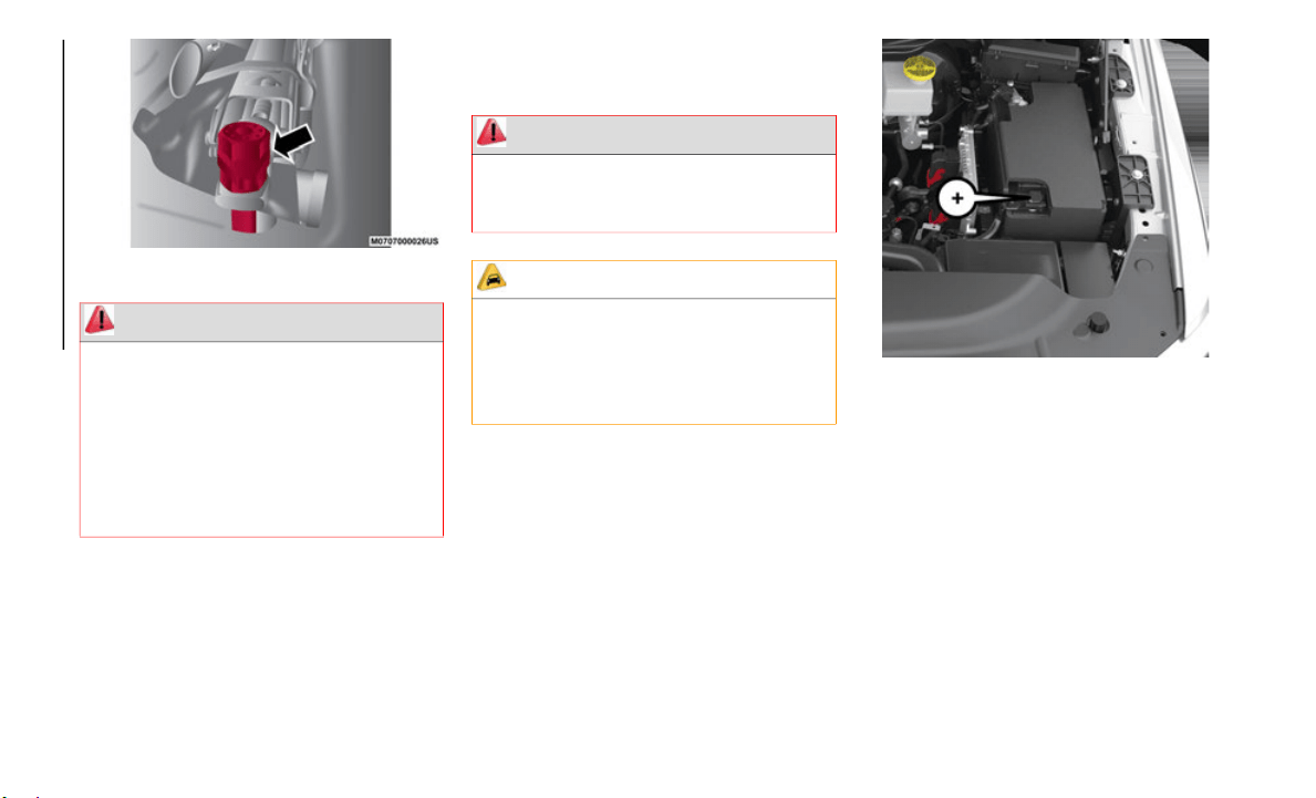
IN CASE OF EMERGENCY
196
Jack Hold Down Wing Bolt
JUMP STARTING
If your vehicle has a discharged battery, it
can be jump started using a set of jumper
cables and a battery in another vehicle, or by
using a portable battery booster pack. Jump
starting can be dangerous if done improp
-
erly, so please follow the procedures in this
section c
arefully.
NOTE:
When using a portable battery booster pack,
follow th
e manufacturer's operating instruc-
tions and precautions.
Preparations For Jump Start
The battery in your vehicle is located in the
front of the engine compartment, behind the
left headlight assembly.
Positive Jumping Location
NOTE:
The positive battery post may be covered
w
ith a protective cap if equipped. Lift up on
the cap to gain access to the positive battery
post. Do not jump off fuses. Only jump
directly off positive post which has a positive
(+) symbol on or around the post.
WARNING!
After using the jack and tools, always
reinstall them in the original carrier and
location. While driving you may experience
abrupt stopping, rapid acceleration or
sharp turns. A loose jack, tools, bracket or
other objects in the vehicle may move
around with force, resulting in serious
injury.
WARNING!
Do not attempt jump starting if the battery
is frozen. It could rupture or explode and
cause personal injury.
CAUTION!
Do not use a portable battery booster pack
or any other booster source with a system
voltage greater than 12 Volts or damage to
the battery, starter motor, alternator or
electrical system may occur.
197
1. Apply the parking brake, shift the auto-
matic transmission into PARK and turn
the ignit
ion OFF.
2. Turn off the heater, radio, and all unnec-
essary e
lectrical accessories.
3. I
f using another vehicle to jump start the
battery,
park the vehicle within the
jumper cables’ reach, apply the parking
brake and make sure the ignition is OFF.
Jump Starting Procedure
Connecting The Jumper Cables
1. Connect the positive (+) end o
f the
jumper cable to the positive (+) post of
the discharged vehicle.
NOTE:
Do not jump off fuses. Only jump directly off
positive
post.
2. Connect the opposite end of the positive
(+) jumpe
r cable to the positive (+) post
of the booster battery.
3. Connect the negative (-) end o
f the
jumper cable to the negative (-) post of
the booster battery.
4. Connect the opposite end of the negative
(-) jumpe
r cable to a good engine ground
(exposed metal part of the discharged
vehicle’s engine) away from the battery
and the fuel injection system.
5. Start the engine in the vehicle that has
the boos
ter battery, let the engine idle a
few minutes, and then start the engine in
the vehicle with the discharged battery.
WARNING!
Take care to avoid the radiator cooling
fan whenever the hood is raised. It can
start anytime the ignition switch is ON.
You can be injured by moving fan blades.
Remove any metal jewelry such as rings,
watch bands and bracelets that could
make an inadvertent electrical contact.
You could be seriously injured.
Batteries contain sulfuric acid that can
burn your skin or eyes and generate
hydrogen gas which is flammable and
explosive. Keep open flames or sparks
away from the battery.
WARNING!
Do not allow vehicles to touch each other
as this could establish a ground
connection and personal injury could
result.
WARNING!
Failure to follow this jump starting
procedure could result in personal injury or
property damage due to battery explosion.
CAUTION!
Failure to follow these procedures could
result in damage to the charging system of
the booster vehicle or the discharged
vehicle.
WARNING!
Do not connect the jumper cable to the
negative (-) post of the discharged battery.
The resulting electrical spark could cause
the battery to explode and could result in
personal injury. Only use the specific
ground point, do not use any other
exposed metal parts.

IN CASE OF EMERGENCY
198
6. Once the engine is started, remove the
jumper cables in the reverse sequence:
Disconnecting The Jumper Cables
1. Disconnect the negative (-) end o
f the
jumper cable from the engine ground of
the vehicle with the discharged battery.
2. Disconnect the opposite end of the nega-
tive (-) j
umper cable from the negative (-)
post
of the booster battery.
3. Disconnect the positive (+) end o
f the
jumper cable from the positive (+) post of
the booster battery.
4. Disconnect the opposite end of the posi-
tive (+) j
umper cable from the positive
(+) post
of the vehicle with the
discharged battery.
If frequent jump starting is required to start
your vehi
cle you should have the battery and
charging system inspected at an authorized
dealer.
IF YOUR ENGINE
OVERHEATS
In any of the following situations, you can
reduce the potential for overheating by
taking the appropriate action.
On the highways — slow down.
In city traffic — while stopped, place the
transmission in NEUTRAL, but do not
increase the engine idle speed while
preventing vehicle motion with the brakes.
NOTE:
There are steps that you can take to slow
down an i
mpending overheat condition:
If your air conditioner (A/C) is on, turn it
off. The A/C system adds heat to the
engine cooling system and turning the A/C
off can help remove this heat.
You can also turn the temperature control
to maximum heat, the mode control to
floor and the blower control to high. This
allows the heater core to act as a supple
-
ment to the radiator and aids in removing
heat from
the engine cooling system.
CAUTION!
Do not connect jumper cable to any of the
fuses on the positive battery terminal. The
resulting electrical current will blow the
fuse.
CAUTION!
Accessories plugged into the vehicle power
outlets draw power from the vehicle’s
battery, even when not in use (i.e., cellular
devices, etc.). Eventually, if plugged in
long enough without engine operation, the
vehicle’s battery will discharge sufficiently
to degrade battery life and/or prevent the
engine from starting.
WARNING!
You or others can be badly burned by hot
engine coolant (antifreeze) or steam from
your radiator. If you see or hear steam
coming from under the hood, do not open
the hood until the radiator has had time to
cool. Never try to open a cooling system
pressure cap when the radiator or coolant
bottle is hot.
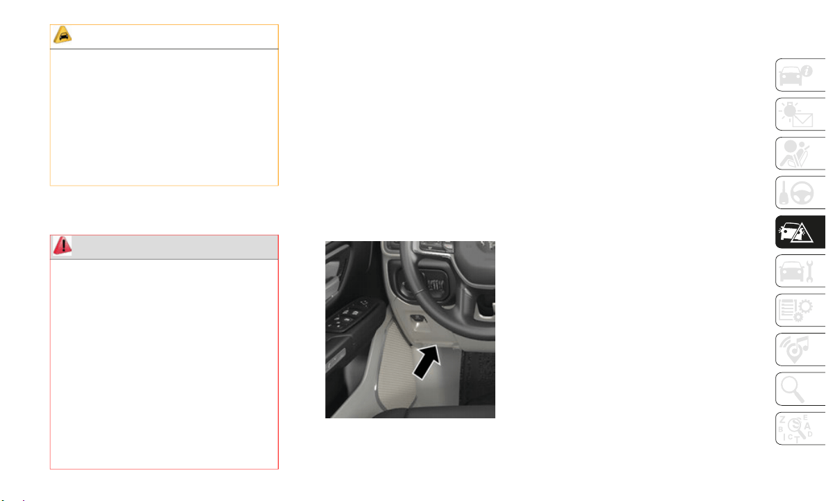
199
MANUAL PARK RELEASE
In order to push or tow the vehicle in cases
where the transmission will not shift out of
PARK (such as a dead battery), a Manual
Park Release is available.
Follow these steps to activate the Manual
Park Rele
ase:
1. Apply the parking brake.
2. Using
a small screwdriver or similar tool,
remove t
he Manual Park Release access
cover, which is just below the Electric
Park Brake switch, below and to the left
of the steering column.
Manual Park Release Access Cover
3. P
ress and maintain firm pressure on the
brake pe
dal.
4. Pull the tether strap to rotate the lever
rearward
, until it locks in place pointing
towards the driver's seat. Verify that the
Manual Park Release lever is locked in
the released position.
5. The vehicle is now out of PARK and can
be towed
. Release the parking brake only
when the vehicle is securely connected to
a tow vehicle.
To Reset The Manual Park Release:
1. R
otate the Manual Park Release lever
forward
to its original position.
2. Pull gently on the tether strap to confirm that
the leve
r is locked in its stowed position.
3. Re-install the access cover.
FREEING A STUCK VEHICLE
If your vehicle becomes stuck in mud, sand, or
snow, it can often be moved using a rocking
motion. Turn the steering wheel right and left to
clear the area around the front wheels. Then shift
back and forth between DRIVE and REVERSE,
while gently pressing the accelerator. Use the
least amount of accelerator pedal pressure that
will maintain the rocking motion, without spin
-
ning the wheels or racing the engine.
CAUTION!
Driving with a hot cooling system could
damage your vehicle. If the temperature
gauge reads HOT (H), pull over and stop
the vehicle. Idle the vehicle with the air
conditioner turned off until the pointer
drops back into the normal range. If the
pointer remains on HOT (H), and you hear
continuous chimes, turn the engine off
immediately and call for service.
WARNING!
Always secure your vehicle by fully
applying the parking brake before
activating the Manual Park Release. In
addition, you should be seated in the
driver’s seat with your foot firmly on the
brake pedal when activating the Manual
Park Release. Activating the Manual Park
Release will allow your vehicle to roll away
if it is not secured by the parking brake, or
by proper connection to a tow vehicle.
Activating the Manual Park Release on an
unsecured vehicle could lead to serious
injury or death for those in or around the
vehicle.

IN CASE OF EMERGENCY
200
NOTE:
For trucks equipped with an 8–speed transmission,
shifts be
tween DRIVE and REVERSE can only be
achieved at wheel speeds of 5
mph (8 km/h) or
less. Whe
never the transmission remains in
NEUTRAL for more than two seconds, you must
press the brake pedal to engage DRIVE or
REVERSE.
NOTE:
Push the “ESC Off” switch, to place the Elec-
tronic Stability Control (ESC) system in “Partial
O
ff” mode
, before rocking the vehicle. Once the
vehicle has been freed, push the “ESC Off” switch
again to restore “ESC On” mode. Refer to “Elec
-
tronic Brake Control” in “Safety” in the Owner’s
Manual fo
r further information.
TOWING A DISABLED
VEHICLE
This section describes procedures for towing a
disabled vehicle using a commercial towing
service.
If the transmission and drivetrain are operable,
disabled
vehicles may also be towed as
described under “Recreational Towing” in the
“Starting And Operating” section.-.5
NOTE:
Vehicles equipped with the Active-Level Four
Corner Ai
r Suspension System must be placed
in Transport mode, before tying them down
(from the body) on a trailer or flatbed truck. If
the vehicle cannot be placed in Transport mode
(for example, engine will not run), tie-downs
must be fastened to the axles (not to the body).
Failure to follow these instructions may cause
fault codes to be set and/or cause loss of proper
tie-down tension.
Refer to "Active-Level Four Corner Air Suspen-
sion System — If Equipped" in "Starting And
Operating
" for more information.
WARNING!
Fast spinning tires can be dangerous. Forces
generated by excessive wheel speeds may
cause damage, or even failure, of the axle
and tires. A tire could explode and injure
someone. Do not spin your vehicle's wheels
faster than 30
mph (48 km/h) or for longer
than 30 s
econds continuously without
stopping when you are stuck and do not let
anyone near a spinning wheel, no matter
what the speed.
CAUTION!
Racing the engine or spinning the wheels
may lead to transmission overheating
and failure. Allow the engine to idle with
the transmission in NEUTRAL for at
least one minute after every five
rocking-motion cycles. This will mini
-
mize overheating and reduce the risk of
t
ransmiss
ion failure during prolonged
efforts to free a stuck vehicle.
When “rocking” a stuck vehicle by
shifting between DRIVE and REVERSE,
do not spin the wheels faster than
15
mph (24 km/h), or drivetrain damage
may resul
t.
Revving the engine or spinning the
wheels too fast may lead to transmission
overheating and failure. It can also
damage the tires. Do not spin the wheels
above 30
mph (48 km/h) while in gear
(no trans
mission shifting occurring).
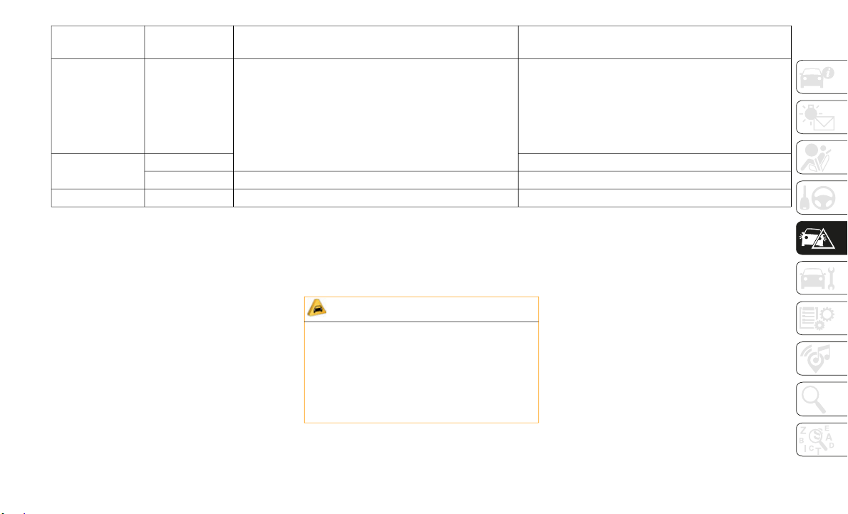
201
Proper towing or lifting equipment is
required to prevent damage to your vehicle.
Use only tow bars and other equipment
designed for this purpose, following equip
-
ment manufacturer’s instructions. Use of
safety ch
ains is mandatory. Attach a tow bar
or other towing device to main structural
members of the vehicle, not to bumpers or
associated brackets. State and local laws
regarding vehicles under tow must be
observed.
If you must use the accessories (wipers,
defroster
s, etc.) while being towed, the igni-
tion must be in the ON/RUN mode, not the
A
CC mode.
I
f the key fob is unavailable or the vehicle's
battery i
s discharged, refer to ”Manual Park
Release” in this section for instructions on
shifting the transmission out of PARK for
towing.
Two-Wheel Drive Models
The manufacturer recommends towing your
vehicle with all four wheels OFF the ground
using a flatbed.
If flatbed equipment is not available, and the
transmiss
ion is operable, the vehicle may be
towed (with rear wheels on the ground) under
the following conditions:
The transmission must be in NEUTRAL.
Towing
Condition
W
heels OFF The
Ground
2WD Models 4WD Models
Flat Tow NONE If transmission is operable:
Transmission in NEUTRAL
30 mph (48 km/h) max speed
30 miles (48 km) max distance (8–speed trans-
mission)
See instructions in “Recreational Towing” under
“Starting
And Operating”
Automatic Transmission in PARK
Transfer Case in NEUTRAL (N)
Tow in forward direction
Wheel Lift Or
Dolly Tow
F
ront NOT ALLOWED
Rear OK NOT ALLOWED
Flatbed ALL BEST METHOD BEST METHOD
CAUTION!
Do not use sling type equipment when
towing. Vehicle damage may occur.
When securing the vehicle to a flat bed
truck, do not attach to front or rear
suspension components. Damage to your
vehicle may result from improper towing.

IN CASE OF EMERGENCY
202
NOTE:
Refer to "Manual Park Release" in this
section f
or instructions on shifting the trans-
mission to NEUTRAL when the engine is
O
FF.
The towing speed must not exceed
30 mph (48 km/h).
The towing distance must not exceed
30 miles (48 km) for 8–speed transmis-
sion.
If the transmission is not operable, or the
v
ehicle m
ust be towed faster than 30 mph
(48 km/h)
or farther than 30 miles (48 km)
for 8–spe
ed transmission, tow with the rear
wheels OFF the ground. Acceptable methods
are to tow the vehicle on a flatbed, or with
the front wheels raised and the rear wheels
on a towing dolly, or (when using a suitable
steering wheel stabilizer to hold the front
wheels in the straight position) with the rear
wheels raised and the front wheels on the
ground.
Four-Wheel Drive Models
The manufacturer recommends towing with
all wheels OFF the ground. Acceptable
methods are to tow the vehicle on a flatbed
or with one end of vehicle raised and the
opposite end on a towing dolly.
If flatbed equipment is not available, and the
transfer
case is operable, the vehicle may be
towed (in the forward direction, with ALL
wheels on the ground), IF the transfer case is
in NEUTRAL (N) and the transmission is in
PARK.
Refer to “Recreational Towing” in “Starting
And Opera
ting” for further information and
detailed instructions.
Emergency Tow Hooks — If Equipped
Your vehicle may be equipped with emer-
gency tow hooks.
NOTE:
For off-road recovery, it is recommended to
u
se both
of the front tow hooks to minimize
the risk of damage to the vehicle.
CAUTION!
Towing this vehicle in violation of the
above requirements can cause severe
transmission damage. Damage from
improper towing is not covered under the
New Vehicle Limited Warranty.
CAUTION!
Front or rear wheel lifts must not be used
(if the remaining wheels are on the
ground). Internal damage to the trans
-
mission or transfer case will occur if a
front or
rear wheel lift is used when
towing.
Towing this vehicle in violation of the
above requirements can cause severe
transmission and/or transfer case
damage. Damage from improper towing
is not covered under the New Vehicle
Limited Warranty.
203
ENHANCED ACCIDENT
RESPONSE SYSTEM (EARS)
This vehicle is equipped with an Enhanced
Accident Response System.
Please refer to “Occupant Restraint
Systems”
in “Safety” for further information
on the Enhanced Accident Response System
(EARS) function.
EVENT DATA RECORDER
(EDR)
This vehicle is equipped with an Event Data
Recorder (EDR). The main purpose of an
EDR is to record data that will assist in
understanding how a vehicle’s systems
performed under certain crash or near
crash-like situations, such as an air bag
deployment or hitting a road obstacle.
Please refer to “Occupant Restraint
Systems”
in “Safety” for further information
on the Event Data Recorder (EDR).
WARNING!
Do not use a chain for freeing a stuck
vehicle. Chains may break, causing
serious injury or death.
Stand clear of vehicles when pulling with
tow hooks. Tow straps may become
disengaged, causing serious injury.
CAUTION!
Tow hooks are for emergency use only, to
rescue a vehicle stranded off road. Do not
use tow hooks for tow truck hookup or
highway towing. You could damage your
vehicle.

204
SERVICING AND MAINTENANCE
SCHEDULED SERVICING
Your vehicle is equipped with an automatic
oil change indicator system. The oil change
indicator system will remind you that it is
time to take your vehicle in for scheduled
maintenance.
Based on engine operation conditions, the oil
change in
dicator message will illuminate.
This means that service is required for your
vehicle. Operating conditions such as
frequent short-trips, trailer tow, and
extremely hot or cold ambient temperatures
will influence when the “Oil Change
Required” message is displayed. Severe
Operating Conditions can cause the change
oil message to illuminate as early as
3,500
miles (5,600 km) since last reset.
Have your
vehicle serviced as soon as
possible, within the next 500
miles
(805 km).
Yo
ur authorized dealer will reset the oil
change in
dicator message after completing
the scheduled oil change. If a scheduled oil
change is performed by someone other than
your authorized dealer, the message can be
reset by referring to the steps described
under “Instrument Cluster Display” in
“Getting To Know Your Instrument Panel”.
NOTE:
Under no circumstances should oil change
intervals
exceed 10,000 miles (16,000 km),
twelve mo
nths or 350 hours of engine run time,
whichever comes first. The 350 hours of engine
run or idle time is generally only a concern for
fleet customers.
Severe Duty All Models
NOTE:
Change Engine Oil at 4,000 miles (6,500 km)
o
r 350 ho
urs of engine run time if the vehicle
is operated in a dusty and off road environment
or is operated predominantly at idle, or only
very low engine RPM’s. This type of vehicle use
is considered Severe Duty.
Once A Month Or Before A Long Trip:
Check engine oil level.
Check windshield washer fluid level.
Check tire pressure and look for unusual
wear or damage. Rotate tires at the first
sign of irregular wear, even if it occurs
before the oil indicator system turns on.
Check the fluid levels of the coolant reser-
voir, brake master cylinder, and fill as
needed.
Check function of all interior and exterior
lights.

205
Maintenance Plan
Required Maintenance
Refer to the Maintenance Plan on the following pages for required maintenance.
At Every Oil Change Interval As Indicated By Oil Change Indicator System:
Change oil and filter.
Rotate the tires. Rotate at the first sign of irregular wear, even if it occurs before the oil indicator system turns on.
Inspect battery and clean and tighten terminals as required.
Inspect brake pads, shoes, rotors, drums, and hoses.
Inspect engine cooling system protection and hoses.
Inspect exhaust system.
Inspect engine air cleaner if using in dusty or off-road conditions.
Mileage or time passed
(whichever comes first)
20,000
30,000
40,000
50,00
0
60,00
0
70,00
0
80,00
0
90,00
0
100,0
00
110
,000
120
,000
130
,000
140
,000
150
,000
Or Years: 2 3 4 5 6 7 8 9 10 11 12 13 14 15
Or Kilometers:
32,000
48,000
64,000
80,00
0
96,00
0
112,0
00
128
,000
144
,000
160
,000
176
,000
192
,000
208
,000
224
,000
240
,000
Additional Inspections
Inspect the CV/Universal joints. X X X X X
Inspect front suspension, tie rod
e
nds, and
replace if necessary.
X X X X X X X

SERVICING AND MAINTENANCE
206
Inspect the front and rear axle
surfaces. If gear oil leakage is
suspected, check the fluid level. If
using your vehicle for police, taxi,
fleet, off-road or frequent trailer
towing, change axle fluid.
X X X X X
Inspect the brake linings, replace as
necessary
.
X X X X X X X
Inspect transfer case fluid for the
following
conditions: heavy usage,
off-road, fleet/taxi, etc
X X X
Additional Maintenance
Replace cabin air filter. X X X X X X X
Replace engine air filter. X X X X X
If equipped with Stop/Start replace
a
ccessory
drive belt with OEM grade
Mopar belt.
X
Replace spark plugs
1
.
X
Mileage or time passed
(whichever comes first)
20,000
30,000
40,000
50,000
60,000
70,000
80,000
90,000
100,000
110,000
120,000
130,000
140,000
150,000
Or Years: 2 3 4 5 6 7 8 9 10 11 12 13 14 15
Or Kilometers:
32,000
48,000
64,000
80,000
96,000
112,000
128,000
144,000
160,000
176,000
192,000
208,000
224,000
240,000

207
Flush and replace the engine
coolant at 10 years or
150,000
miles (240,000 km)
whichever
comes first.
X X
Inspect the transfer case fluid,
change for
any of the following:
police, taxi, fleet, or frequent trailer
towing.
X X
Change the transfer case fluid. X
Inspect and replace PCV valve if
n
ecessary.
X
1. The spark plug change interval is mileage based only, yearly intervals do not apply.
Mileage or time passed
(whichever comes first)
20,000
30,000
40,000
50,000
60,000
70,000
80,000
90,000
100,000
110,000
120,000
130,000
140,000
150,000
Or Years: 2 3 4 5 6 7 8 9 10 11 12 13 14 15
Or Kilometers:
32,000
48,000
64,000
80,000
96,000
112,000
128,000
144,000
160,000
176,000
192,000
208,000
224,000
240,000

SERVICING AND MAINTENANCE
208
Heavy Duty Use Of The Vehicle
Change engine oil at 4,000 miles
(6,500 km) or 350 hours of engine run time
if the ve
hicle is operated in a dusty and off
road environment or is operated predomi
-
nately at idle or only very low engine RPM’s.
This type
of vehicle use is considered Severe
Duty.
WARNING!
You can be badly injured working on or
around a motor vehicle. Do only service
work for which you have the knowledge
and the right equipment. If you have any
doubt about your ability to perform a
service job, take your vehicle to a compe
-
tent mechanic.
Failure to properly inspect and maintain
your vehicle could result in a component
malfunction and effect vehicle handling
and performance. This could cause an
accident.
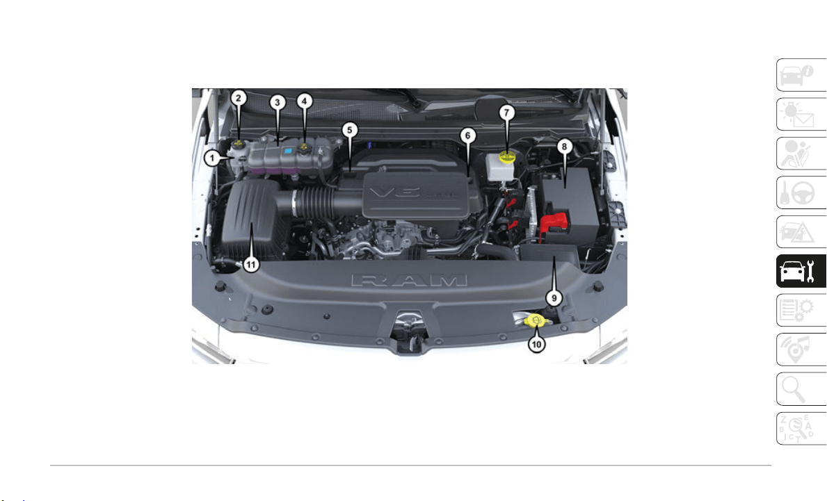
209
ENGINE COMPARTMENT
3.6L Engine With Stop/Start
1 — Motor Generator Unit Coolant Reservoir Pressure Cap 7 — Battery
2 — Engine Coolant Reservoir 8 — Power Distribution Center (Fuses)
3 — Engine Coolant Reservoir Pressure Cap 9 — Washer Fluid Reservoir
4 — Engine Oil Dipstick 10 — Air Cleaner Filter
5 — Engine Oil Fill 11 — Motor Generator Unit Coolant Reservoir
6 — Brake Fluid Reservoir
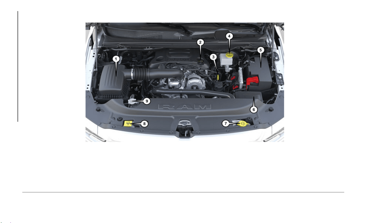
SERVICING AND MAINTENANCE
210
5.7L Engine Without Stop/Start
1 — Air Cleaner Filter 6 — Power Distribution Center (Fuses)
2 — Engine Oil Fill 7 — Washer Fluid Reservoir
3 — Engine Oil Dipstick 8 — Engine Coolant Reservoir
4 — Brake Fluid Reservoir 9 — Engine Coolant Pressure Cap
5 — Battery
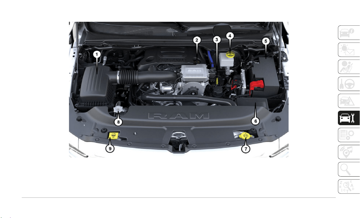
211
5.7L Engine With Stop/Start
1 — Air Cleaner Filter 6 — Power Distribution Center
2 — Engine Oil Fill 7 — Washer Fluid Reservoir
3 — Engine Oil Dipstick 8 — Engine Coolant Pressure Cap
4 — Brake Fluid Reservoir 9 — Engine Coolant Reservoir
5 — Battery
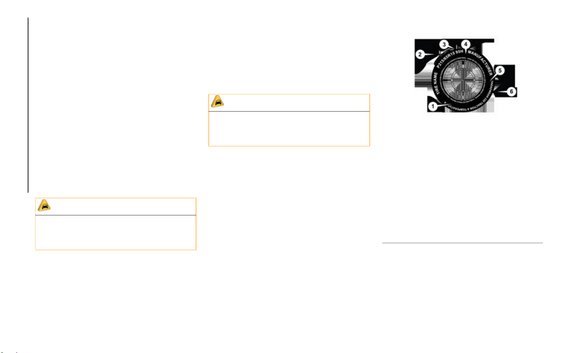
SERVICING AND MAINTENANCE
212
Checking Oil Level
To assure proper lubrication of your vehicle's
engine, the engine oil must be maintained at
the correct level. Check the oil level at
regular intervals, such as every fuel stop. The
best time to check the engine oil level is
about five minutes after a fully warmed up
engine is shut off.
Checking the oil while the vehicle is on level
ground wi
ll improve the accuracy of the oil
level readings. Always maintain the oil level
within the SAFE zone on the dipstick. Adding
one quart of oil when the reading is at the
bottom of the SAFE zone will result in a
reading at the top of the safe zone on these
engines.
HOISTING
A conventional floor jack may be used at the
jacking locations. Refer to the graphics that
show jacking locations. However, a floor jack
or frame hoist must never be used on any
other parts of the underbody.
TIRES
Tire Safety Information
Tire safety information will cover aspects of
the following information: Tire Markings, Tire
Identification Numbers, Tire Terminology
and Definitions, Tire Pressures, and Tire
Loading.
Tire Markings
Tire Markings
CAUTION!
Overfilling or underfilling will cause oil
aeration or loss of oil pressure. This could
damage your engine.
CAUTION!
Never use a floor jack directly under the
differential housing of a loaded truck or
damage to your vehicle may result.
1 — U.S. DOT Safety Standards
Code (TIN)
2 — Size Designation
3 — Service Description
4 — Maximum Load
5 — Maximum Pressure
6 — Treadwear, Traction and Tem-
perature Grades

213
NOTE:
P (Passenger) — Metric tire sizing is based
on U.S. design standards. P-Metric tires
have the letter “P” molded into the sidewall
preceding the size designation. Example:
P215/65R15 95H.
European — Metric tire sizing is based on
European design standards. Tires designed
to this standard have the tire size molded
into the sidewall beginning with the section
width. The letter "P" is absent from this tire
size designation. Example: 215/65R15
96H.
LT (Light Truck) — Metric tire sizing is
based on U.S. design standards. The size
designation for LT-Metric tires is the same as
for P-Metric tires except for the letters “LT”
that are molded into the sidewall preceding
the size designation. Example: LT235/
85R16.
Temporary spare tires are designed for
temporary emergency use only. Temporary
high pressure compact spare tires have the
letter “T” or “S” molded into the sidewall
preceding the size designation. Example:
T145/80D18 103M.
High flotation tire sizing is based on U.S.
design standards and it begins with the tire
diameter molded into the sidewall. Example:
31x10.5 R15 LT.
Tire Sizing Chart
EXAMPLE:
Example Size Designation: P215/65R15XL 95H, 215/65R15 96H, LT235/85R16C, T145/80D18 103M, 31x10.5 R15 LT
P = Passenger car tire size based on U.S. design standards, or
"....blank...."
= Passen
ger car tire based on European design standards, or
LT = Light truck tire based on U.S. design standards, or
T or S =
Temporary spare tire or
31 = Overa
ll diameter in inches (in)
215, 235
, 145 = Sectio
n width in millimeters (mm)
65, 85, 80 = Aspect ratio in percent (%)
Ratio of section height to section width of tire, or
10.5 = Section width in inches (in)

SERVICING AND MAINTENANCE
214
R = Construction code
"R" means radial construction, or
"D" means diagonal or bias construction
15, 16, 18 = Rim diameter in inches (in)
Service
Description:
95
= Load Index
A numerical code associated with the maximum load a tire can carry
H = Speed Symbol
A symbol indicating the range of speeds at which a tire can carry a load corresponding to its load index under certain operating conditions
The maximum speed corresponding to the speed symbol should only be achieved under specified operating conditions (i.e., tire pressure,
vehicle loading, road conditions, and posted speed limits)
Load Identification:
Absence of the following load identification symbols on the sidewall of the tire indicates a Standard Load (SL) tire:
XL = Extra load (or reinforced) tire, or
LL = Light load tire or
C, D, E, F, G = Load range associated with the maximum load a tire can carry at a specified pressure
Maximum Load – Maximu
m load indicates the maximum load this tire is designed to carry
Maximum Pressure – Maximu
m pressure indicates the maximum permissible cold tire inflation pressure for this tire
EXAMPLE:

215
Tire Identification Number (TIN)
The TIN may be found on one or both sides of the tire; however, the date code may only be on one side. Tires with white sidewalls will have
the full TIN, including the date code, located on the white sidewall side of the tire. Look for the TIN on the outboard side of black sidewall
tires as mounted on the vehicle. If the TIN is not found on the outboard side, then you will find it on the inboard side of the tire.
EXAMPLE:
DOT MA L9 ABCD 0301
DOT = Department of Transportation
This symbol certifies that the tire is in compliance with the U.S. Department of Transportation tire safety standards and is approved for
highway use
MA = Code representing the tire manufacturing location (two digits)
L9 = Code
representing the tire size (two digits)
ABCD = Co
de used by the tire manufacturer (one to four digits)
03 = Numbe
r representing the week in which the tire was manufactured (two digits)
03 means the 3rd week
01 = Number representing the year in which the tire was manufactured (two digits)
01 means the year 2001
Prior to July 2000, tire manufacturers were only required to have one number to represent the year in which the tire was manufactured.
Example: 031 could represent the 3rd week of 1981 or 1991
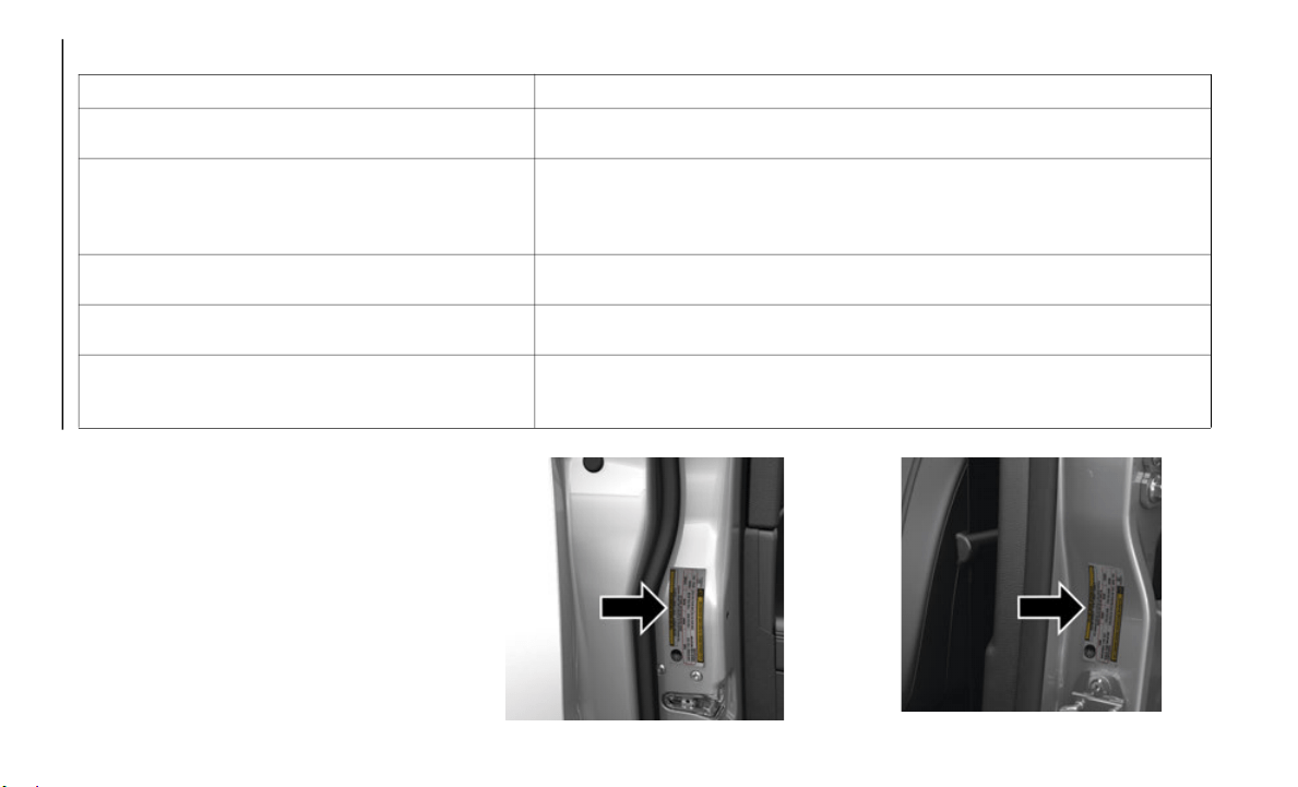
SERVICING AND MAINTENANCE
216
Tire Terminology And Definitions
Tire Loading And Tire Pressure
NOTE:
The proper cold tire inflation pressure is
listed on
the driver’s side B-Pillar or the rear
edge of the driver's side door.
Check the inflation pressure of each tire,
including
the spare tire (if equipped), at
least monthly and inflate to the recom
-
mended pressure for your vehicle.
Example Tire Placard Location (Door)
Example Tire Placard Location (B-Pillar)
Term Definition
B-Pillar The vehicle B-Pillar is the structural member of the body located behind the front
door.
Cold Tire Inflation Pressure Cold tire inflation pressure is defined as the tire pressure after the vehicle has not
been driv
en for at least three hours, or driven less than 1 mile (1.6 km) after
sitting f
or a minimum of three hours. Inflation pressure is measured in units of
PSI (pounds per square inch) or kPa (kilopascals).
Maximum Inflation Pressure The maximum inflation pressure is the maximum permissible cold tire inflation
pressure
for this tire. The maximum inflation pressure is molded into the sidewall.
Recommended Cold Tire Inflation Pressure Vehicle manufacturer's recommended cold tire inflation pressure as shown on the
tire plac
ard.
Tire Placard A label permanently attached to the vehicle describing the vehicle’s loading
capacity,
the original equipment tire sizes and the recommended cold tire
inflation pressures.
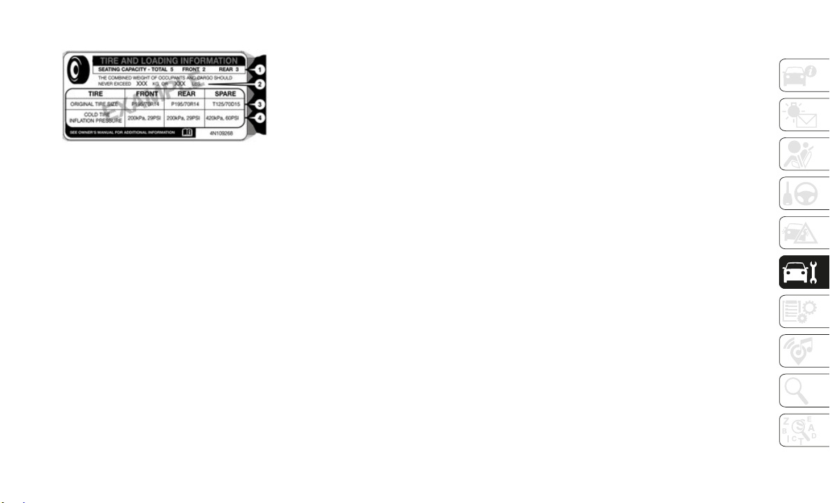
217
Tire And Loading Information Placard
Tire And Loading Information Placard
This placard tells you important information
about the:
1
. Number of people that can be carried in the
vehicle.
2.
Total weight your vehicle can carry.
3. Tire si
ze designed for your vehicle.
4. Cold ti
re inflation pressures for the front,
rear, and
spare tires.
Loading
The vehicle maximum load on the tire must not
exceed the load carrying capacity of the tire on
your vehicle. You will not exceed the tire's load
carrying capacity if you adhere to the loading
conditions, tire size, and cold tire inflation
pressures specified on the Tire and Loading
Information placard in “Vehicle Loading” in the
“Starting And Operating” section of this
manual.
NOTE:
Under a maximum loaded vehicle condition,
g
ross axle
weight ratings (GAWRs) for the front
and rear axles must not be exceeded.
To determine the maximum loading conditions
of your ve
hicle, locate the statement “The
combined weight of occupants and cargo
should never exceed XXX kg or XXX lbs” on the
Tire and Loading Information placard. The
combined weight of occupants, cargo/luggage
and trailer tongue weight (if applicable) should
never exceed the weight referenced here.
Steps For Determining Correct Load
Limit—
(1) Locate the statement “The
combined w
eight of occupants and
cargo should never exceed XXX kg or
XXX lbs.” on your vehicle's placard.
(2) Determine the combined weight of
the driver
and passengers that will be
riding in your vehicle.
(3) Subtract the combined weight of
the driver
and passengers from XXX kg
or XXX lbs.
(4) The resulting figure equals the
available
amount of cargo and luggage
load capacity. For example, if “XXX”
amount equals 1400 lbs. and there
will be five 150 lb passengers in your
vehicle, the amount of available cargo
and luggage load capacity is 650 lbs.
(1400-750 (5x150) = 650 lbs.)
(5) Determine the combined weight of
luggage an
d cargo being loaded on the
vehicle. That weight may not safely
exceed the available cargo and
luggage load capacity calculated in
Step 4.
(6) If your vehicle will be towing a
trailer, l
oad from your trailer will be
transferred to your vehicle. Consult
this manual to determine how this
reduces the available cargo and
luggage load capacity of your vehicle.
Metric Example For Load Limit
For example, if “XXX” amount equals 635 kg
and there
will be five 68 kg passengers in
your vehicle, the amount of available cargo
and luggage load capacity is 295 kg
(635-340 (5x68) = 295 kg) as shown in step
4.

SERVICING AND MAINTENANCE
218
NOTE:
If your vehicle will be towing a trailer, load from your trailer will be transferred to your vehicle. The following table shows examples on how
to calculate total load, cargo/luggage, and towing capacities of your vehicle with varying seating configurations and number and size of
occupants. This table is for illustration purposes only and may not be accurate for the seating and load carry capacity of your vehicle.
For the following example, the combined weight of occupants and cargo should never exceed 865 lbs (392 kg).

219
(Continued)
Tires — General Information
Tire Pressure
Proper tire inflation pressure is essential to
the safe and satisfactory operation of your
vehicle. Four primary areas are affected by
improper tire pressure:
Safety
Fuel Economy
Tread Wear
Ride Comfort and Vehicle Stability
Safety
Both under-inflation and over-inflation affect
the stabi
lity of the vehicle and can produce
a feeling of sluggish response or over respon
-
siveness in the steering.
NOTE:
Unequal tire pressures from side to side
may cause erratic and unpredictable
steering response.
Unequal tire pressure from side to side
may cause the vehicle to drift left or right.
Fuel Economy
Underinflated tires will increase tire rolling
r
esistanc
e resulting in higher fuel consump-
tion.
Tread Wear
Improper cold tire inflation pressures can
c
ause abn
ormal wear patterns and reduced
tread life, resulting in the need for earlier tire
replacement.
Ride Comfort And Vehicle Stability
Proper tire inflation contributes to a comfort-
able ride. Over-inflation produces a jarring
and uncom
fortable ride.
Tire Inflation Pressures
The proper cold tire inflation pressure is
listed on the driver's side B-Pillar or rear
edge of the driver's side door.
WARNING!
Overloading of your tires is dangerous.
Overloading can cause tire failure, affect
vehicle handling, and increase your
stopping distance. Use tires of the
recommended load capacity for your
vehicle. Never overload them.
WARNING!
Improperly inflated tires are dangerous
and can cause collisions.
Underinflation increases tire flexing and
can result in overheating and tire failure.
Overinflation reduces a tire's ability to
cushion shock. Objects on the road and
chuckholes can cause damage that
result in tire failure.
Overinflated or underinflated tires can
affect vehicle handling and can fail
suddenly, resulting in loss of vehicle
control.
Unequal tire pressures can cause
steering problems. You could lose
control of your vehicle.
Unequal tire pressures from one side of
the vehicle to the other can cause the
vehicle to drift to the right or left.
Always drive with each tire inflated to the
recommended cold tire inflation pres-
sure.
WARNING! (Continued)

SERVICING AND MAINTENANCE
220
At least once a month:
Check and adjust tire pressure with a good
quality pocket-type pressure gauge. Do not
make a visual judgement when deter
-
mining proper inflation. Tires may look
properly
inflated even when they are
under-inflated.
Inspect tires for signs of tire wear or visible
damage.
Inflation pressures specified on the placard
are alway
s “cold tire inflation pressure”.
Cold tire inflation pressure is defined as the
tire pressure after the vehicle has not been
driven for at least three hours, or driven less
than 1
mile (1.6 km) after sitting for a
minimum o
f three hours. The cold tire infla-
tion pressure must not exceed the maximum
i
nflation
pressure molded into the tire side-
wall.
Check tire pressures more often if subject to
a wide ra
nge of outdoor temperatures, as tire
pressures vary with temperature changes.
Tire pressures change by approximately 1 psi
(7 kPa) p
er 12°F (7°C) of air temperature
change. Keep this in mind when checking
tire pressure inside a garage, especially in
the Winter.
Example: If garage temperature = 68°F
(20°C) an
d the outside temperature = 32°F
(0°C) then the cold tire inflation pressure
should be increased by 3 psi (21 kPa), which
equals 1 psi (7 kPa) for every 12°F (7°C) for
this outside temperature condition.
Tire pressure may increase from 2 to 6 psi
(13 to 40
kPa) during operation. DO NOT
reduce this normal pressure build up or your
tire pressure will be too low.
Tire Pressures For High Speed Operation
The manufacturer advocates driving at safe
speeds and within posted speed limits.
Where speed limits or conditions are such
that the vehicle can be driven at high speeds,
maintaining correct tire inflation pressure is
very important. Increased tire pressure and
reduced vehicle loading may be required for
high-speed vehicle operation. Refer to an
authorized tire dealer or original equipment
vehicle dealer for recommended safe oper
-
ating speeds, loading and cold tire inflation
p
ressures
.
Radial Ply Tires
CAUTION!
After inspecting or adjusting the tire
pressure, always reinstall the valve stem
cap. This will prevent moisture and dirt
from entering the valve stem, which could
damage the valve stem.
WARNING!
High speed driving with your vehicle under
maximum load is dangerous. The added
strain on your tires could cause them to
fail. You could have a serious collision. Do
not drive a vehicle loaded to the maximum
capacity at continuous speeds above
75
mph (120 km/h).
WARNING!
Combining radial ply tires with other types
of tires on your vehicle will cause your
vehicle to handle poorly. The instability
could cause a collision. Always use radial
ply tires in sets of four. Never combine
them with other types of tires.
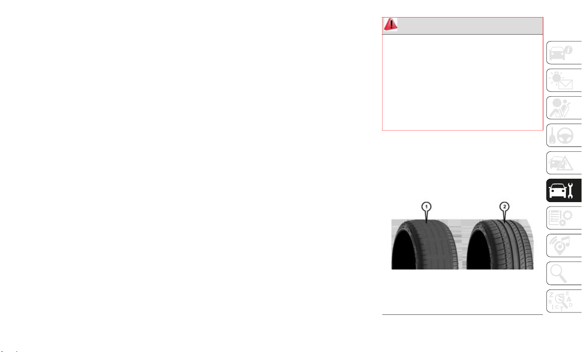
221
Tire Repair
If your tire becomes damaged, it may be
repaired
if it meets the following criteria:
The tire has not been driven on when flat.
The damage is only on the tread section of
your tire (sidewall damage is not repair-
able).
The puncture is no greater than a ¼ of an
inch (6 mm).
Consult an authorized tire dealer for tire
repairs a
nd additional information.
Damaged Run Flat tires, or Run Flat tires
that have
experienced a loss of pressure
should be replaced immediately with another
Run Flat tire of identical size and service
description (Load Index and Speed Symbol).
Replace the tire pressure sensor as well as it
is not designed to be reused.
Run Flat Tires — If Equipped
Run Flat tires allow you the capability to drive
50 miles (80 km) at 50 mph (80 km/h) after
a rapid l
oss of inflation pressure. This rapid
loss of inflation is referred to as the Run Flat
mode. A Run Flat mode occurs when the tire
inflation pressure is of/or below 14 psi (96
kPa). Once a Run Flat tire reaches the run flat
mode it has limited driving capabilities and
needs to be replaced immediately. A Run Flat
tire is not repairable. When a run flat tire is
changed after driving with underinflated tire
condition, please replace the TPM sensor as it
is not designed to be reused when driven
under run flat mode (14 psi (96 kPa)) condi
-
tion.
NOTE:
TPM Sensor must be replaced after driving
the vehic
le on a flat tire condition.
It is not recommended driving a vehicle
loaded at
full capacity or to tow a trailer
while a tire is in the run flat mode.
See the tire pressure monitoring section for
more info
rmation.
Tire Spinning
When stuck in mud, sand, snow, or ice
conditions, do not spin your vehicle's wheels
above 30
mph (48 km/h) or for longer than
30 second
s continuously without stopping.
Refer to “Freeing A Stuck Vehicle” in “In
Case Of E
mergency” for further information.
Tread Wear Indicators
Tread wear indicators are in the original
equipment tires to help you in determining
when your tires should be replaced.
Tire Tread
WARNING!
Fast spinning tires can be dangerous.
Forces generated by excessive wheel
speeds may cause tire damage or failure. A
tire could explode and injure someone. Do
not spin your vehicle's wheels faster than
30
mph (48 km/h) for more than 30
seconds c
ontinuously when you are stuck,
and do not let anyone near a spinning
wheel, no matter what the speed.
1 — Worn Tire
2 — New Tire

SERVICING AND MAINTENANCE
222
These indicators are molded into the bottom
of the tread grooves. They will appear as
bands when the tread depth becomes a 1/16
of an inch (1.6
mm). When the tread is worn
to the tre
ad wear indicators, the tire should
be replaced.
Refer to “Replacement Tires” in this section
for furthe
r information.
Life Of Tire
The service life of a tire is dependent upon
varying factors including, but not limited to:
Driving style.
Tire pressure - Improper cold tire inflation
pressures can cause uneven wear patterns
to develop across the tire tread. These
abnormal wear patterns will reduce tread
life, resulting in the need for earlier tire
replacement.
Distance driven.
Performance tires, tires with a speed
rating of V or higher, and Summer tires
typically have a reduced tread life. Rota
-
tion of these tires per the vehicle sched-
uled maintenance is highly recommended.
NOTE:
Wheel Valve Stem must be replaced as well
when insta
lling new tires due to wear and
tear in existing tires.
Keep dismounted tires in a cool, dry place
with as li
ttle exposure to light as possible.
Protect tires from contact with oil, grease,
and gasoline.
Replacement Tires
The tires on your new vehicle provide a
balance of many characteristics. They should
be inspected regularly for wear and correct
cold tire inflation pressures. The manufac
-
turer strongly recommends that you use tires
equivalent
to the originals in size, quality
and performance when replacement is
needed. Refer to the paragraph on “Tread
Wear Indicators” in this section. Refer to the
Tire and Loading Information placard or the
Vehicle Certification Label for the size desig
-
nation of your tire. The Load Index and
S
peed Symb
ol for your tire will be found on
the original equipment tire sidewall.
See the Tire Sizing Chart example found in
the “Tire
Safety Information” section of this
manual for more information relating to the
Load Index and Speed Symbol of a tire.
It is recommended to replace the two front
tires or t
wo rear tires as a pair. Replacing just
one tire can seriously affect your vehicle’s
handling. If you ever replace a wheel, make
sure that the wheel’s specifications match
those of the original wheels.
It is recommended you contact an authorized
tire deale
r or original equipment dealer with
any questions you may have on tire specifica
-
tions or capability. Failure to use equivalent
replacemen
t tires may adversely affect the
safety, handling, and ride of your vehicle.
WARNING!
Tires and the spare tire should be replaced
after six years, regardless of the remaining
tread. Failure to follow this warning can
result in sudden tire failure. You could lose
control and have a collision resulting in
serious injury or death.

223
Tire Types
All Season Tires — If Equipped
All Season tires provide traction for all
seasons (Spring, Summer, Fall, and Winter).
Traction levels may vary between different all
season tires. All season tires can be identi
-
fied by the M+S, M&S, M/S or MS designa-
tion on the tire sidewall. Use all season tires
only in s
ets of four; failure to do so may
adversely affect the safety and handling of
your vehicle.
Summer Or Three Season Tires — If
Equipped
Summer tires provide traction in both wet
and dry conditions, and are not intended to
be driven in snow or on ice. If your vehicle is
equipped with Summer tires, be aware these
tires are not designed for Winter or cold
driving conditions. Install Winter tires on
your vehicle when ambient temperatures are
less than 40°F (5°C) or if roads are covered
with ice or snow. For more information,
contact an authorized dealer.
Summer tires do not contain the all season
designati
on or mountain/snowflake symbol
on the tire sidewall. Use Summer tires only
in sets of four; failure to do so may adversely
affect the safety and handling of your
vehicle.
Snow Tires
Some areas of the country require the use of
snow tires during the Winter. Snow tires can
be identified by a “mountain/snowflake”
symbol on the tire sidewall.
If you need snow tires, select tires
equivalent in size and type to the
original
equipment tires. Use snow
tires only in sets of four; failure to
do so may adversely affect the safety and
handling of your vehicle.
WARNING!
Do not use a tire, wheel size, load rating,
or speed rating other than that specified
for your vehicle. Some combinations of
unapproved tires and wheels may change
suspension dimensions and performance
characteristics, resulting in changes to
steering, handling, and braking of your
vehicle. This can cause unpredictable
handling and stress to steering and
suspension components. You could lose
control and have a collision resulting in
serious injury or death. Use only the tire
and wheel sizes with load ratings
approved for your vehicle.
Never use a tire with a smaller load index
or capacity, other than what was origi-
nally equipped on your vehicle. Using a
t
ire with
a smaller load index could result
in tire overloading and failure. You could
lose control and have a collision.
Failure to equip your vehicle with tires
having adequate speed capability can
result in sudden tire failure and loss of
vehicle control.
CAUTION!
Replacing original tires with tires of a
different size may result in false
speedometer and odometer readings.
WARNING!
Do not use Summer tires in snow/ice
conditions. You could lose vehicle control,
resulting in severe injury or death. Driving
too fast for conditions also creates the
possibility of loss of vehicle control.

SERVICING AND MAINTENANCE
224
Snow tires generally have lower speed ratings
than what was originally equipped with your
vehicle and should not be operated at
sustained speeds over 75
mph (120 km/h).
For speed
s above 75 mph (120 km/h) refer
to origin
al equipment or an authorized tire
dealer for recommended safe operating
speeds, loading and cold tire inflation pres
-
sures.
While studded tires improve performance on
ice, skid
and traction capability on wet or dry
surfaces may be poorer than that of
non-studded tires. Some states prohibit
studded tires; therefore, local laws should be
checked before using these tire types.
Spare Tires — If Equipped
NOTE:
For vehicles equipped with Tire Service Kit
instead o
f a spare tire, please refer to “Tire
Service Kit” in “In Case Of Emergency” in
the Owner’s Manual for further information.
Refer to the “Towing Requirements - Tires”
in “Start
ing And Operating” in the Owner’s
Manual for restrictions when towing with a
spare tire designated for temporary emer
-
gency use.
Spare Tire Matching Original Equipped Tire
And Wheel — If Equipped
Your vehicle may be equipped with a spare
tire and wheel equivalent in look and func-
tion to the original equipment tire and wheel
f
ound on
the front or rear axle of your vehicle.
This spare tire may be used in the tire rota
-
tion for your vehicle. If your vehicle has this
option, r
efer to an authorized tire dealer for
the recommended tire rotation pattern.
Compact Spare Tire — If Equipped
The compact spare is for temporary emer-
gency use only. You can identify if your
vehicle i
s equipped with a compact spare by
looking at the spare tire description on the
Tire and Loading Information Placard
located on the driver’s side door opening or
on the sidewall of the tire. Compact spare
tire descriptions begin with the letter “T” or
“S” preceding the size designation.
Example: T145/80D18 103M.
T, S = Temporary Spare Tire
Since this tire has limited tread life, the orig-
inal equipment tire should be repaired (or
r
eplaced)
and reinstalled on your vehicle at
the first opportunity.
Do not install a wheel cover or attempt to
mount a c
onventional tire on the compact
spare wheel, since the wheel is designed
specifically for the compact spare tire. Do
not install more than one compact spare tire
and wheel on the vehicle at any given time.
Collapsible Spare Tire — If Equipped
The collapsible spare is for temporary emer-
gency use only. You can identify if your
vehicle i
s equipped with a collapsible spare
by looking at the spare tire description on the
CAUTION!
Because of the reduced ground clearance,
do not take your vehicle through an
automatic car wash with a compact or
limited use temporary spare installed.
Damage to the vehicle may result.
WARNING!
Compact and collapsible spares are for
temporary emergency use only. With these
spares, do not drive more than 50
mph
(80 km/h).
Temporary use spares have
limited t
read life. When the tread is worn
to the tread wear indicators, the temporary
use spare tire needs to be replaced. Be
sure to follow the warnings, which apply to
your spare. Failure to do so could result in
spare tire failure and loss of vehicle
control.
225
Tire and Loading Information Placard
located on the driver’s side door opening or
on the sidewall of the tire.
Collapsible spare tire description example:
165/80-17
101P.
Since this tire has limited tread life, the orig-
inal equipment tire should be repaired (or
r
eplaced)
and reinstalled on your vehicle at
the first opportunity.
Inflate collapsible tire only after the wheel is
properly
installed to the vehicle. Inflate the
collapsible tire using the electric air pump
before lowering the vehicle.
Do not install a wheel cover or attempt to
mount a c
onventional tire on the collapsible
spare wheel, since the wheel is designed
specifically for the collapsible spare tire.
Full Size Spare — If Equipped
The full size spare is for temporary emer-
gency use only. This tire may look like the
originall
y equipped tire on the front or rear
axle of your vehicle, but it is not. This spare
tire may have limited tread life. When the
tread is worn to the tread wear indicators, the
temporary use full size spare tire needs to be
replaced. Since it is not the same as your
original equipment tire, replace (or repair)
the original equipment tire and reinstall on
the vehicle at the first opportunity.
Limited Use Spare — If Equipped
The limited use spare tire is for temporary
emergency use only. This tire is identified by
a label located on the limited use spare
wheel. This label contains the driving limita
-
tions for this spare. This tire may look like
the origi
nal equipped tire on the front or rear
axle of your vehicle, but it is not. Installation
of this limited use spare tire affects vehicle
handling. Since it is not the same as your
original equipment tire, replace (or repair)
the original equipment tire and reinstall on
the vehicle at the first opportunity.
Wheel And Wheel Trim Care
All wheels and wheel trim, especially
aluminum and chrome plated wheels, should
be cleaned regularly using mild (neutral Ph)
WARNING!
Compact and Collapsible spares are for
temporary emergency use only. With these
spares, do not drive more than 50
mph
(80 km/h).
Temporary use spares have
limited t
read life. When the tread is worn
to the tread wear indicators, the temporary
use spare tire needs to be replaced. Be
sure to follow the warnings, which apply to
your spare. Failure to do so could result in
spare tire failure and loss of vehicle
control.
WARNING!
Limited use spares are for emergency use
only. Installation of this limited use spare
tire affects vehicle handling. With this tire,
do not drive more than the speed listed on
the limited use spare wheel. Keep inflated
to the cold tire inflation pressures listed on
your Tire and Loading Information Placard
located on the driver’s side B-Pillar or the
rear edge of the driver’s side door. Replace
(or repair) the original equipment tire at
the first opportunity and reinstall it on your
vehicle. Failure to do so could result in
loss of vehicle control.

SERVICING AND MAINTENANCE
226
soap and water to maintain their luster and
to prevent corrosion. Wash wheels with the
same soap solution recommended for the
body of the vehicle and remember to always
wash when the surfaces are not hot to the
touch.
Your wheels are susceptible to deterioration
caused by
salt, sodium chloride, magnesium
chloride, calcium chloride, etc., and other
road chemicals used to melt ice or control
dust on dirt roads. Use a soft cloth or sponge
and mild soap to wipe away promptly. Do not
use harsh chemicals or a stiff brush. They
can damage the wheel’s protective coating
that helps keep them from corroding and
tarnishing.
When cleaning extremely dirty wheels
including
excessive brake dust, care must be
taken in the selection of tire and wheel
cleaning chemicals and equipment to
prevent damage to the wheels. Mopar Wheel
Treatment or Mopar Chrome Cleaner or their
equivalent is recommended or select a
non-abrasive, non-acidic cleaner for
aluminum or chrome wheels.
NOTE:
If you intend parking or storing your vehicle
for an ex
tended period after cleaning the
wheels with wheel cleaner, drive your vehicle
and apply the brakes to remove the water
droplets from the brake components. This
activity will remove the red rust on the brake
rotors and prevent vehicle vibration when
braking.
Dark Vapor Chrome, Black Satin Chrome, or
Low Gloss
Clear Coat Wheels
DEPARTMENT OF
TRANSPORTATION
UNIFORM TIRE QUALITY
GRADES
The following tire grading categories
were established by the National
Highway Traffic Safety Administra-
tion. The specific grade rating
assigned
by the tire's manufacturer in
each category is shown on the side-
wall of the tires on your vehicle.
CAUTION!
Avoid products or automatic car washes
that use acidic solutions or strong alkaline
additives or harsh brushes. Many
aftermarket wheel cleaners and automatic
car washes may damage the wheel's
protective finish. Such damage is not
covered by the New Vehicle Limited
Warranty. Only car wash soap, Mopar
Wheel Cleaner or equivalent is
recommended.
CAUTION!
Do not use scouring pads, steel wool, a
bristle brush, metal polishes or oven
cleaner. These products may damage the
wheel's protective finish. Such damage is
not covered by the New Vehicle Limited
Warranty. Only car wash soap, Mopar
Wheel Cleaner or equivalent is
recommended.
CAUTION!
If your vehicle is equipped with these
specialty wheels, DO NOT USE wheel
cleaners, abrasives, or polishing
compounds. They will permanently
damage this finish and such damage is not
covered by the New Vehicle Limited
Warranty. HAND WASH ONLY USING
MILD SOAP AND WATER WITH A SOFT
CLOTH. Used on a regular basis; this is all
that is required to maintain this finish.
227
All passenger vehicle tires must
conform to Federal safety require-
ments in addition to these grades.
Treadwear
The Treadwear grade is a comparative
rating, based on the wear rate of the
tire when tested under controlled
conditions on a specified government
test course. For example, a tire graded
150 would wear one and one-half
times as well on the government
course as a tire graded 100. The rela-
tive performance of tires depends
upon the
actual conditions of their
use, however, and may depart signifi-
cantly from the norm due to variations
in drivin
g habits, service practices,
and differences in road characteristics
and climate.
Traction Grades
The Traction grades, from highest to
lowest, are AA, A, B, and C. These
grades represent the tire's ability to
stop on wet pavement, as measured
under controlled conditions on speci-
fied government test surfaces of
asphalt a
nd concrete. A tire marked C
may have poor traction performance.
Temperature Grades
The Temperature grades are A (the
highest), B, and C, representing the
tire's resistance to the generation of
heat and its ability to dissipate heat,
when tested under controlled condi-
tions on a specified indoor laboratory
test whee
l.
Sustained high temperature can
cause the
material of the tire to
degenerate and reduce tire life, and
excessive temperature can lead to
sudden tire failure. The grade C corre-
sponds to a level of performance,
which all
passenger vehicle tires must
meet under the Federal Motor Vehicle
Safety Standard No. 109. Grades B
and A represent higher levels of
performance on the laboratory test
wheel, than the minimum required by
law.
WARNING!
The traction grade assigned to this tire is
based on straight-ahead braking traction
tests, and does not include acceleration,
cornering, hydroplaning, or peak traction
characteristics.
WARNING!
The temperature grade for this tire is
established for a tire that is properly
inflated and not overloaded. Excessive
speed, under-inflation, or excessive
loading, either separately or in
combination, can cause heat buildup and
possible tire failure.

228
TECHNICAL SPECIFICATIONS
WHEEL AND TIRE TORQUE
SPECIFICATIONS
Proper lug nut/bolt torque is very important
to ensure that the wheel is properly mounted
to the vehicle. Any time a wheel has been
removed and reinstalled on the vehicle, the
lug nuts/bolts should be torqued using a
properly calibrated torque wrench using a
high quality six sided (hex) deep wall socket.
Torque Specifications
**Use only your authorized dealer recom-
mended lug nuts/bolts and clean or remove
any dirt
or oil before tightening.
NOTE:
Do not oil wheel studs. For chrome wheels,
d
o not su
bstitute with chrome plated wheel
nuts.
Inspect the wheel mounting surface prior to
mounting
the tire and remove any corrosion
or loose particles.
Tighten the lug nuts/bolts in a star pattern
until eac
h nut/bolt has been tightened twice.
Ensure that the socket is fully engaged on
the lug nut/bolt (do not insert it halfway).
After 25 miles (40 km), check the lug nut/
bolt torq
ue to be sure that all the lug nuts/
bolts are properly seated against the wheel.
FLUID CAPACITIES
Lug Nut/Bolt
Torque
Lug Nut/
Bolt Type
**Lug
Nut/Bolt
Size
Lug Nut/
Bolt
Socket
Size
130 Ft-Lbs
(176 N·m)
Co
ne M14 x
1.50
22 mm
WARNING!
To avoid the risk of forcing the vehicle off
the jack, do not tighten the lug nuts/bolts
fully until the vehicle has been lowered.
Failure to follow this warning may result in
personal injury.
U.S. Metric
Fuel (Approximate)
1500 Regular Cab Shortbed/Crew Quad Cab Models 23 Gallons 87 Liters
1500 Regular Cab Shortbed/Crew Quad Cab Models 26 Gallons 98 Liters
1500 Regular Cab Longbed/Crew Quad Cab Models (Optional) 33 Gallons 121 Liters
Engine Oil With Filter
3.6L Engine (We recommend you use SAE 0W-20, API Certified) 5 Quarts 4.7 Liters

229
FLUIDS AND LUBRICANTS
Engine
5.7L Engines (We recommend you use SAE 5W-20, API Certified) 7 Quarts 6.6 Liters
Cooling System
3.6L Engine (We recommend you use Mopar Antifreeze/Coolant 10 Year/150,000
M
ile Form
ula that meets the requirements of FCA Material Standard MS.90032.)
13.7 Quarts 13 Liters
3.6L Motor Generator Unit (We recommend you use Mopar Antifreeze/Coolant 10
Year/150,
000 Mile Formula that meets the requirements of FCA Material Standard
MS.90032.)
1.8 Quarts 1.7 Liters
5.7L Engine – 1500 Models (We recommend you use Mopar Antifreeze/Coolant 10
Year/150,
000 Mile Formula that meets the requirements of FCA Material Standard
MS.90032.)
18.3 Quarts 17.3 Liters
U.S. Metric
Component Fluid, Lubricant, or Genuine Part
Engine Coolant We recommend you use Mopar Antifreeze/Coolant 10 Year/150,000
Mile Formula OAT (Organic Additive Technology).
Motor Generator Unit (If Equipped) We recommend you use Mopar Antifreeze/Coolant 10 Year/150,000
Mile Form
ula OAT (Organic Additive Technology).
Engine Oil – 3.6L Engine We recommend you use API Certified SAE 0W-20 Engine Oil,
meeting t
he requirements of FCA Material Standard MS-6395 such
as Mopar, Pennzoil, and Shell Helix. Refer to your engine oil filler
cap for correct SAE grade.

TECHNICAL SPECIFICATIONS
230
(Continued)
Engine Oil – 5.7L Engine We recommend you use API Certified SAE 5W-20 Engine Oil,
meeting the requirements of FCA Material Standard MS-6395 such
as Mopar, Pennzoil, and Shell Helix. Refer to your engine oil filler
cap for correct SAE grade.
Engine Oil Filter We recommend you use Mopar brand Engine Oil Filters.
Spark Plugs We recommend you use Mopar Spark Plugs.
Fuel Selection – 3.6L Engine 87 Octane, 0-15% Ethanol (Do not use E-85).
Fuel Selection – 5.7L Engines 89 Octane Recommended - 87 Octane Acceptable, 0-15% Ethanol
(
Do not u
se E-85).
Component Fluid, Lubricant, or Genuine Part
CAUTION!
Mixing of engine coolant (antifreeze)
other than specified Organic Additive
Technology (OAT) engine coolant (anti
-
freeze), may result in engine damage
and may d
ecrease corrosion protection.
Organic Additive Technology (OAT)
engine coolant is different and should
not be mixed with Hybrid Organic Addi
-
tive Technology (HOAT) engine coolant
(antifree
ze) or any “globally compatible”
coolant (antifreeze). If a non-OAT engine
coolant (antifreeze) is introduced into
the cooling system in an emergency, the
cooling system will need to be drained,
flushed, and refilled with fresh OAT
coolant (conforming to MS.90032), by
an authorized dealer as soon as possible.
Do not use water alone or alcohol-based
engine coolant (antifreeze) products. Do
not use additional rust inhibitors or anti
-
rust products, as they may not be
compatibl
e with the radiator engine
coolant and may plug the radiator.
This vehicle has not been designed for
use with propylene glycol-based engine
coolant (antifreeze). Use of propylene
glycol-based engine coolant (antifreeze)
is not recommended.
CAUTION! (Continued)

231
Chassis
Component Fluid, Lubricant, or Genuine Part
Automatic Transmission Use only Mopar ZF 8&9 Speed ATF Automatic Transmission Fluid, or
equivalent. Failure to use the correct fluid may affect the function or
performance of your transmission.
Transfer Case – 48-11 Active On-Demand 2–speed Transfer Case
(With 4WD
AUTO)
We recommend you use MOPAR Transfer Case Lubricant for Borg
Warner 44-44 and 44-45.
Transfer Case – 48-12 Part Time 2–Speed Transfer Case (Without
4WD AUTO)
W
e recommend you use MOPAR Transfer Case Lubricant for Borg
Warner 44-45, 44-46, 44-47, 44-48 and Pre 2016 44-44.
Front Axle We recommend you use Mopar GL-5 Synthetic Axle Lubricant SAE
75W-85.
Rea
r Axle (3.21/3.55) We recommend you use Mopar Synthetic Gear Lubricant SAE
75W-90 (M
S-A0160). Limited-Slip Rear Axles require the addition
of 5 oz. (148
ml) Mopar Limited Slip Additive (MS-10111).
Rear Axle (3.92) We recommend you use Mopar Synthetic Gear Lubricant SAE
7
5W-140 (
MS-8985). Limited-Slip Rear Axles require the addition
of 5 oz. (148
ml) Mopar Limited Slip Additive (MS-10111).
Max Tow Rear Axle (3.92) We Recommend You Use Dana SAE 80W90 Axle Lubricant.
Brake Master Cylinder We recommend you use Mopar DOT 3. If DOT 3 brake fluid is not
a
vailable
, then DOT 4 is acceptable.

TECHNICAL SPECIFICATIONS
232
MOPAR ACCESSORIES
Authentic Accessories By Mopar
In choosing Authentic Accessories you gain far more than expressive style, premium protection, or extreme entertainment, you also benefit from
enhancing your vehicle with accessories that have been thoroughly tested and factory-approved.
The following highlights just some of the many Authentic Ram Accessories by Mopar featuring a fit, finish, and functionality specifically for your
Ram.
For the full line of Authentic Ram Accessories by Mopar, visit your local dealership or online at mopar.com for U.S. residents and mopar.ca for
Canadian residents
NOTE:
All parts are subject to availability.
Kicker is a registered trademark of Stillwater Designs and Audio, Inc.
EXTERIOR:
• Tonneau Covers • Molded Splash Guards • Bed Step
• Front Air Deflector • Running Boards
INTERIOR:
• All Weather Mats • Wireless Charging • Console Safe
• Premium Carpet Mats
ELECTRONICS:
• Kicker Sound Systems • Remote Start • Wireless Charging Kit
• Electronic Vehicle Tracking
CARRIERS:
• Steel Ladder Rack • Cargo Bed Divider • Cargo Ramps

233
CYBERSECURITY
Your vehicle may be a connected vehicle and
may be equipped with both wired and wire-
less networks. These networks allow your
v
ehicle to
send and receive information. This
information allows systems and features in
your vehicle to function properly.
Your vehicle may be equipped with certain
security f
eatures to reduce the risk of unau-
thorized and unlawful access to vehicle
s
ystems an
d wireless communications.
Vehicle software technology continues to
evolve over time and FCA US LLC, working
with its suppliers, evaluates and takes appro
-
priate steps as needed. Similar to a
computer o
r other devices, your vehicle may
require software updates to improve the
usability and performance of your systems or
to reduce the potential risk of unauthorized
and unlawful access to your vehicle systems.
The risk of unauthorized and unlawful access
to your ve
hicle systems may still exist, even
if the most recent version of vehicle software
(such as Uconnect software) is installed.
NOTE:
FCA US LLC or your dealer may contact
you directly regarding software updates.
To help further improve vehicle security
and minimize the potential risk of a secu-
rity breach, vehicle owners should:
Routinely check www.driveucon-
nect.com (U.S. Residents) or
www.driveuconnect.ca (Canadian Resi-
dents) to learn about available Uconnect
s
oftware u
pdates.
Only connect and use trusted media
devices (e.g. personal mobile phones,
USBs, CDs).
Privacy of any wireless and wired communi-
cations cannot be assured. Third parties may
u
nlawfully
intercept information and private
communications without your consent. For
further information, refer to ”Data Collection
& Privacy” in your Uconnect Owner’s Manual
Supplement or “Onboard Diagnostic System
(OBD II) Cybersecurity” in “Getting To Know
Your Instrument Panel” in your Owner’s
Manual.
WARNING!
It is not possible to know or to predict all
of the possible outcomes if your vehicle’s
systems are breached. It may be possible
that vehicle systems, including safety
related systems, could be impaired or a
loss of vehicle control could occur that
may result in an accident involving
serious injury or death.
ONLY insert media (e.g., USB, SD card,
or CD) into your vehicle if it came from a
trusted source. Media of unknown origin
could possibly contain malicious soft
-
ware, and if installed in your vehicle, it
may increa
se the possibility for vehicle
systems to be breached.
As always, if you experience unusual
vehicle behavior, take your vehicle to
your nearest authorized dealer immedi
-
ately.
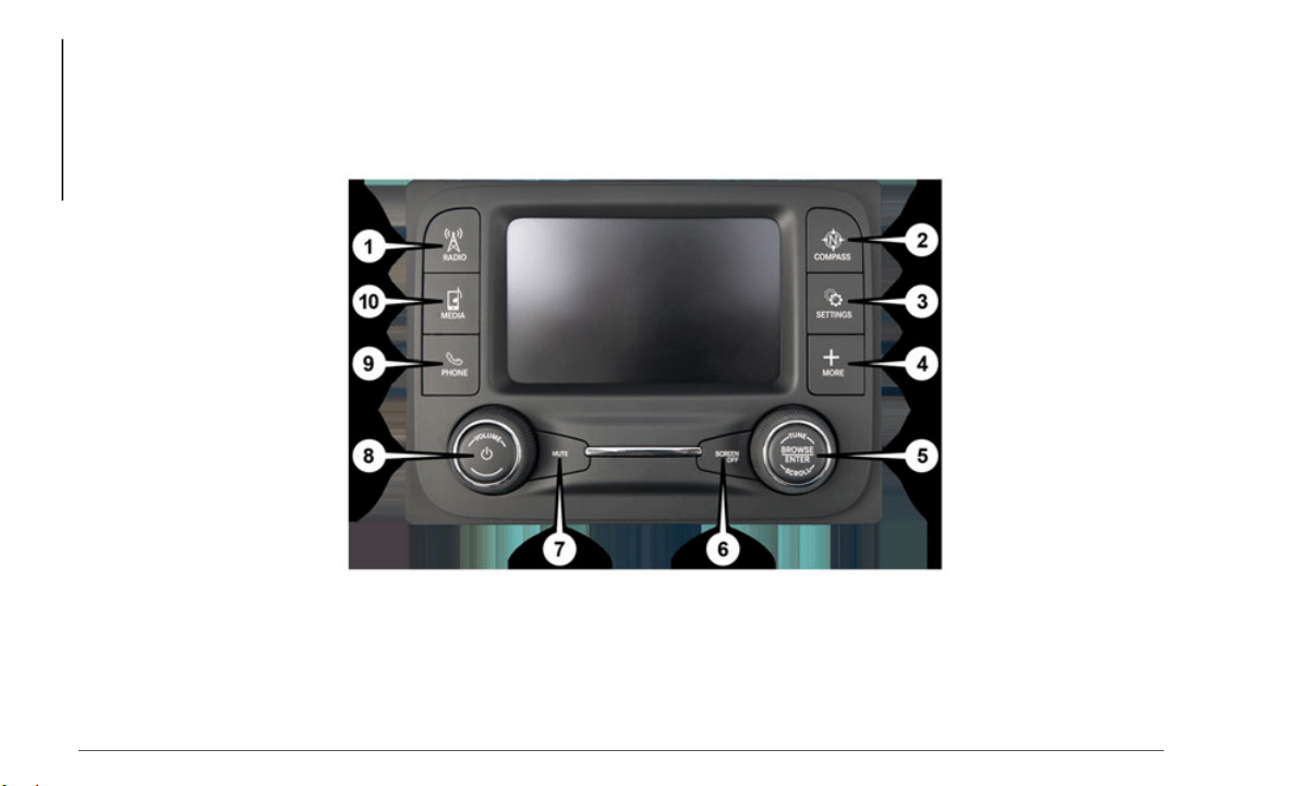
MULTIMEDIA
234
UCONNECT 3 WITH 5–INCH DISPLAY — IF EQUIPPED
Uconnect 3 With 5–inch Display At A Glance
Uconnect 3 With 5–inch Display Radio Buttons
1 — RADIO Button 6 — SCREEN OFF Button
2 — COMPASS Button 7 — MUTE Button
3 — SETTINGS Button 8 — System On/Off — VOLUME Control Knob
4 — MORE Functions Button 9 — Uconnect PHONE Button
5 — BROWSE/ENTER Button — TUNE/SCROLL Knob 10 — MEDIA Button
235
Clock Setting
To start the clock setting procedure:
1. Press the “Settings” button on the face-
plate, t
hen press the “Clock and Date”
button.
2. P
ress the “Set Time” button on the
touchscr
een.
3. Press the “Up” or “Down” arrows to
adjust t
he hours or minutes, then select
the “AM” or “PM” button on the touch
-
screen. You can also select 12hr or 24hr
format by
pressing the desired button on
the touchscreen.
4. Once the time is set, press the “Done”
button o
n the touchscreen to exit the
time screen.
NOTE:
In the Clock Setting Menu you can also
select “D
isplay Clock”. Display Clock turns
the clock display in the status bar on or off.
Audio Setting
1. Press the “Settings” button on the face-
plate.
2. Scroll down and press the “Audio”
button o
n the touchscreen to open the
Audio menu.
3. The Audio Menu shows the following
options
for you to customize your audio
settings.
Equalizer
Press the “Equalizer” button on the touch-
screen to adjust the Bass, Mid and Treble.
U
se the “
+” or “-” button on the touchscreen
to adjust the equalizer to your desired
settings.
Balance/Fade
Press the “Balance/Fade” button on the
touchscre
en to adjust the sound from the
speakers. Use the arrow buttons on the
touchscreen to adjust the sound level from
the front and rear or right and left side
speakers. Press the center “C” button on the
touchscreen to reset the balance and fade to
the factory setting.
Speed Adjusted Volume — If Equipped
Press the “Speed Adjusted Volume” button
on the to
uchscreen to select between OFF,
1, 2 or 3. This will decrease the radio volume
relative to a decrease in vehicle speed.
Loudness — If Equipped
Press the “Loudness” button on the touch-
screen to select the Loudness feature. When
this feat
ure is activated it improves sound
quality at lower volumes.
Surround Sound — If Equipped
Press the “Surround Sound” button on the
touchscre
en, select “On” or “Off” followed
by pressing the back arrow button on the
touchscreen. When this feature is activated,
it provides simulated surround sound mode.
Radio Operation
Store Radio Presets Manually
The Radio stores up to 12 presets in each of
the Radio
modes. There are four visible
presets at the top of the radio screen.
Pressing the “All” button on the touchscreen
on the radio home screen displays all of the
preset stations for that mode.
CAUTION!
Do NOT attach any object to the touchscreen,
doing so can result in damage to the
touchscreen.

MULTIMEDIA
236
To store a radio preset manually, follow the
steps below:
1. Tune to the desired station.
2. Press
and hold the desired numbered
button o
n the touchscreen for more than
two seconds, or until you hear a confir
-
mation beep.
Seek Next/Previous Buttons
Press the Seek Next or Seek Previous
button to seek through radio stations in
AM, FM or SXM bands.
Hold either button to bypass stations
without stopping.
USB/Audio Jack (AUX)/Bluetooth
Operation
USB/AUX
The USB/AUX Jack is located on the Instru-
ment Panel, near the HVAC controls.
USB/iPod Mode is entered by either
inserting a USB Jump Drive or an iPod
cable into the USB port or by pushing the
MEDIA button on the faceplate located
below the display. Once in Media Mode,
press the “Source” button on the touch
-
screen and select USB/iPod.
NOTE:
The USB source will say "iPod" only when an
a
pple pro
duct is connected to the USB port.
Push the MEDIA button on the faceplate,
press the “Source” button on the touch-
screen then select USB/iPod to change
t
he mode
to the USB device. If the device
is connected, music from your portable
device will play through the vehicle's
speakers.
Audio Jack (AUX)
The AUX jack allows a portable device, such
a
s
an MP
3
player or an iPod, to be plugged
into the radio and utilize the vehicle’s audio
system, using a 3.5
mm audio cable, to
amplify t
he source and play through the
vehicle speakers.
Push the MEDIA button on the faceplate,
press the “Source” button on the touch-
screen then select “AUX” to change the
m
ode to A
UX.
The functions of the portable device are
controlled using the device. However, the
volume may be controlled using the radio
or portable device.
Bluetooth
If using a Bluetooth - equipped device, you
m
ay also
be able to stream music to your
vehicle's sound system.
Push the MEDIA button on the faceplate,
press the
“Source” button on the touch-
screen then select “Bluetooth” to change the
m
ode to B
luetooth. If the device is paired,
music from your portable device will play
through the vehicle's speakers.
NOTE:
If changing the name of the device within the
Bluetooth
settings of your device (where
applicable), and the device is connected to
the vehicle Bluetooth system, the system
may change the current playing track.
Uconnect 3 With 5–inch Display Available
Media Hub
s
S = Standard Equipment
O = Optional Equipment
Uconnect 3 Media Hub
(
USB, AUX
P
orts)
Remote USB
Port (Fully
Functional)
S O
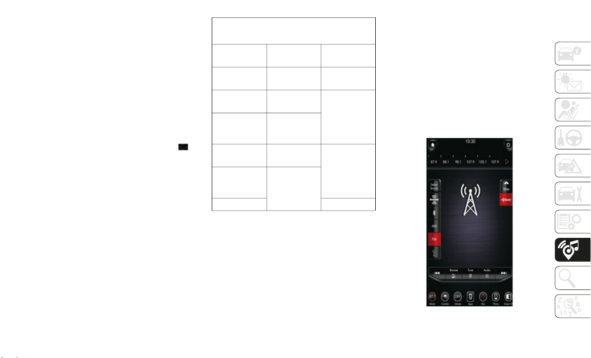
237
Voice Text Reply (Not Compatible With
iPhone)
Once your Uconnect system is paired with a
compatible mobile device, the system can
announce a new incoming text message, and
read it to you over the vehicle audio system.
You can reply to the message using Voice
Recognition by selecting, or saying, one of
the 18 pre-defined messages.
Here’s How:
1. Push the Voice Recognition (VR) or
the Pho
ne button and wait for the beep,
then say “
reply.” Uconnect gives the
following prompt: “Please say the
message you would like to send.”
2. Wait for the beep and say one of the
pre-defin
ed messages. (If you are not
sure, you can say “help”). Uconnect will
then read the pre-defined messages
allowed.
3. As soon as you hear the message you
would lik
e to send, you can interrupt the
list of prompts by pushing the Uconnect
phone button and saying the phrase.
Uconnect will confirm the message by
reading it back to you.
4. Push the Phone button and say “Send.”
*Use only
the numbering listed or the system
may not tr
anscribe the message properly.
Siri Eyes Free — If Equipped
Siri lets you use your voice to send text
m
essages,
select media, place phone calls
and much more. Siri uses natural language
to understand what you mean and responds
back to confirm your requests. The system is
designed to keep your eyes on the road and
your hands on the wheel by letting Siri help
you perform useful tasks.
To enable Siri, push and hold, then release
the Uconne
ct Voice Recognition (VR) button
on the steering wheel. After you hear a
double beep you can ask Siri to play
podcasts and music, get directions, read text
messages and many other useful requests.
UCONNECT 4C NAV WITH
12-INCH DISPLAY
Uconnect 4C NAV At A Glance
Uconnect 4C NAV With 12-inch Display Radio
Screen
PRE-DEFINED VOICE TEXT REPLY
RESPONSES
Yes.
Stuck in
traffic.
See
you
later.
No.
Start without
me.
I’ll be
late.
Okay.
Where are
you?
I will
be <5,
10, 15, 20,
25, 30, 45,
60>*
minutes late.
Call me.
Are you
there yet?
I
’ll call you
later.
I nee
d
directions.
See you in
<5, 10, 15,
20, 25, 30,
45, 60>*
minutes.
I’m on my
way.
Can’t t
alk
right now.
I
’m lost. Thanks.

MULTIMEDIA
238
NOTE:
Uconnect screen images are for illustration
purposes
only and may not reflect exact soft-
ware for your vehicle.
Setting The Time
Model 4C NAV synchronizes time auto-
matically via GPS, so it should not require
any time
adjustment. If you do need to set
the time manually, follow the instructions
below for Model 4C NAV.
For Model 4C, turn the unit on, and then
press the time display at the top of the
screen. Press “Yes.”
If the time is not displayed at the top of
the screen, press the “Settings” button on
the touchscreen. In the Settings screen,
press the “Clock” button on the touch
-
screen, then check or uncheck this option.
Press “+” or “–” next to Set Time Hours
and Set Time Minutes to adjust the time.
If these features are not available,
uncheck the Sync Time box.
Press “X” to save your settings and exit out
of the Clock Setting screen.
Background Themes
Screen background themes are selectable
from a pre-loaded list of themes. If you’d
like to set a theme, follow the instructions
below.
Press the “Settings” button on the touch-
screen.
Press the “Display” button on the touch-
screen.
Then press “Set Theme” button on the
touchscreen and select a theme.
Audio Settings
Press of the “Audio” button on the touch-
screen to activate the Audio settings
screen to
adjust Balance\Fade, Equalizer,
and Speed Adjusted Volume.
You can return to the Radio screen by
pressing the “X” located at the top right.
Balance/Fade
Press the “Balance/Fade” button on the
touchscreen to Balance audio between the
front speakers or fade the audio between
the rear and front speakers.
Pressing the “Front,” “Rear,” “Left,” or
“Right” buttons on the touchscreen or
press and drag the Speaker Icon to adjust
the Balance/Fade.
Equalizer
Press the “Equalizer” button on the touch-
screen to activate the Equalizer screen.
Press the “+” or “–” buttons on the touch-
screen, or press and drag over the level bar
for each
of the equalizer bands. The level
value, which spans between plus or minus
nine, is displayed at the bottom of each of
the Bands.
WARNING!
ALWAYS drive safely with your hands on
the wheel. You have full responsibility and
assume all risks related to the use of the
Uconnect features, SiriusXM Guardian
services, and applications in this vehicle.
Only use Uconnect features and SiriusXM
Guardian services when it is safe to do so.
Failure to do so may result in an accident
involving serious injury or death.
CAUTION!
Do NOT attach any object to the
touchscreen, doing so can result in
damage to the screen.
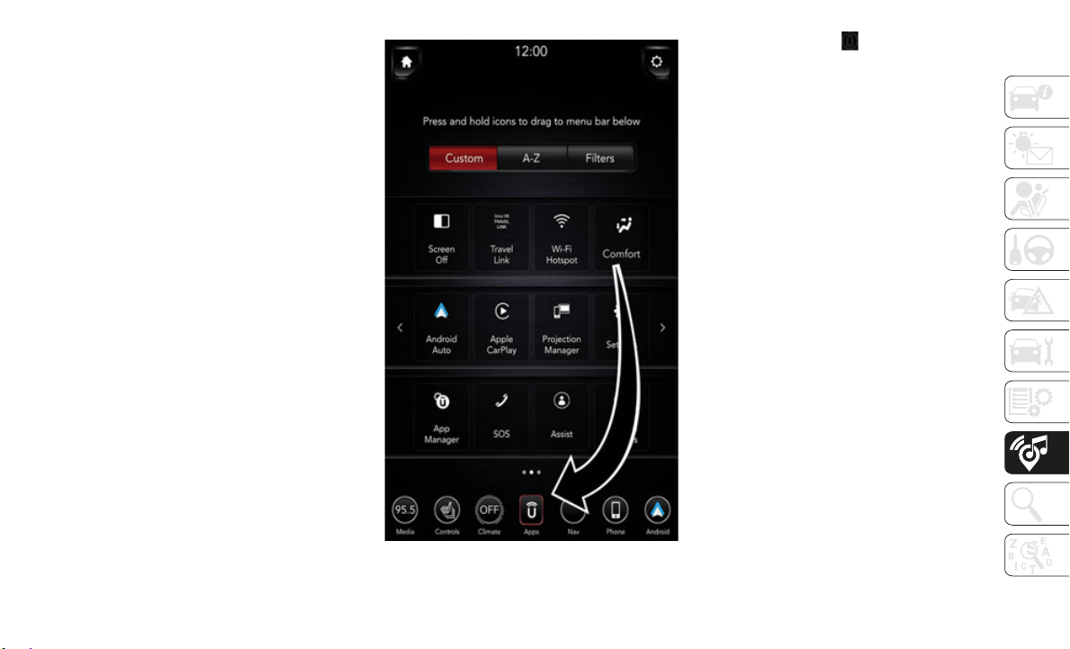
239
Speed Adjusted Volume
Press the “Speed Adjusted Volume”
button on the touchscreen to activate the
Speed Adjusted Volume screen. The
Speed Adjusted Volume is adjusted by
pressing the volume level indicator. This
alters the automatic adjustment of the
audio volume with variation to vehicle
speed.
Drag & Drop Menu Bar
The Uconnect features and services in the
main menu bar are easily changed for your
convenience. Simply follow these steps:
Uconnect 4C NAV Main Menu
1. P
ress the “Apps ” button
to open the
App screen.
2. Press and hold, then drag the selected
App to re
place an existing shortcut in the
main menu bar.
The new app shortcut, that was dragged
down onto
the main menu bar, will now
be an active App/shortcut.
NOTE:
This feature is only available if the vehicle is
in PARK.
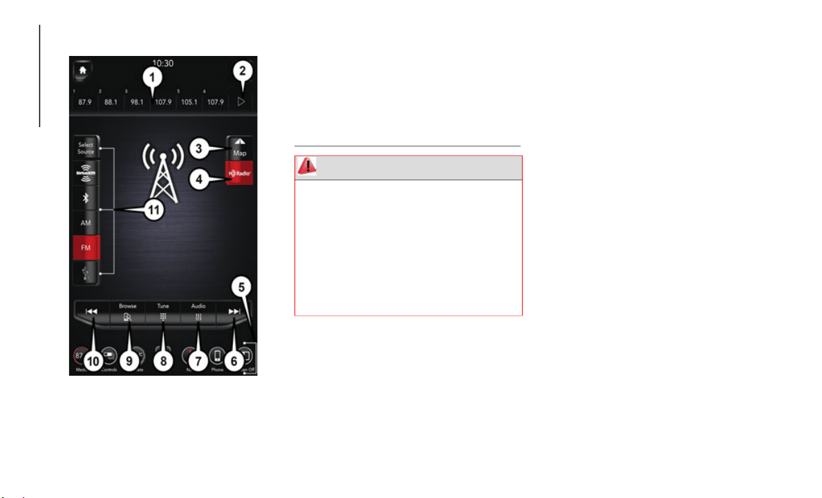
MULTIMEDIA
240
Radio
Uconnect 4C NAV With 12–inch Display Radio
To access the Radio mode, press the
“Radio” button on the touchscreen.
Selecting Radio Stations
Press the desired radio band (AM, FM or
SXM) button on the touchscreen.
Seek Up/Seek Down
Press the Seek up or down arrow buttons
on the touchscreen for less than two
seconds to seek through radio stations.
Press and hold either arrow button on the
touchscreen for more than two seconds to
bypass stations without stopping. The
radio will stop at the next listenable
station once the arrow button on the
touchscreen is released.
Direct Tune
Tune directly to a radio station by pressing
the “Tune” button on the screen, and
entering the desired station number.
Store Radio Presets Manually
Your radio can store 36 total preset stations,
12 preset
s per band (AM, FM and SXM).
They are shown at the top of your radio
screen. To see the 12 preset stations per
band, press the arrow button on the touch
-
screen at the top right of the screen to toggle
between t
he two sets of six presets.
1 — Radio Station Presets
2 — Toggle Between Presets
3 — View Small Navigation Map
4 — HD Radio
5 — Main Category Bar
6 — Seek Up
7 — Audio Settings
8 — Direct Tune To A Radio Station
9 — Browse And Manage Presets
10 — Seek Down
11 — Radio Bands
WARNING!
ALWAYS drive safely with your hands on
the wheel. You have full responsibility and
assume all risks related to the use of the
Uconnect features, SiriusXM Guardian
services, and applications in this vehicle.
Only use Uconnect features and SiriusXM
Guardian services when it is safe to do so.
Failure to do so may result in an accident
involving serious injury or death.
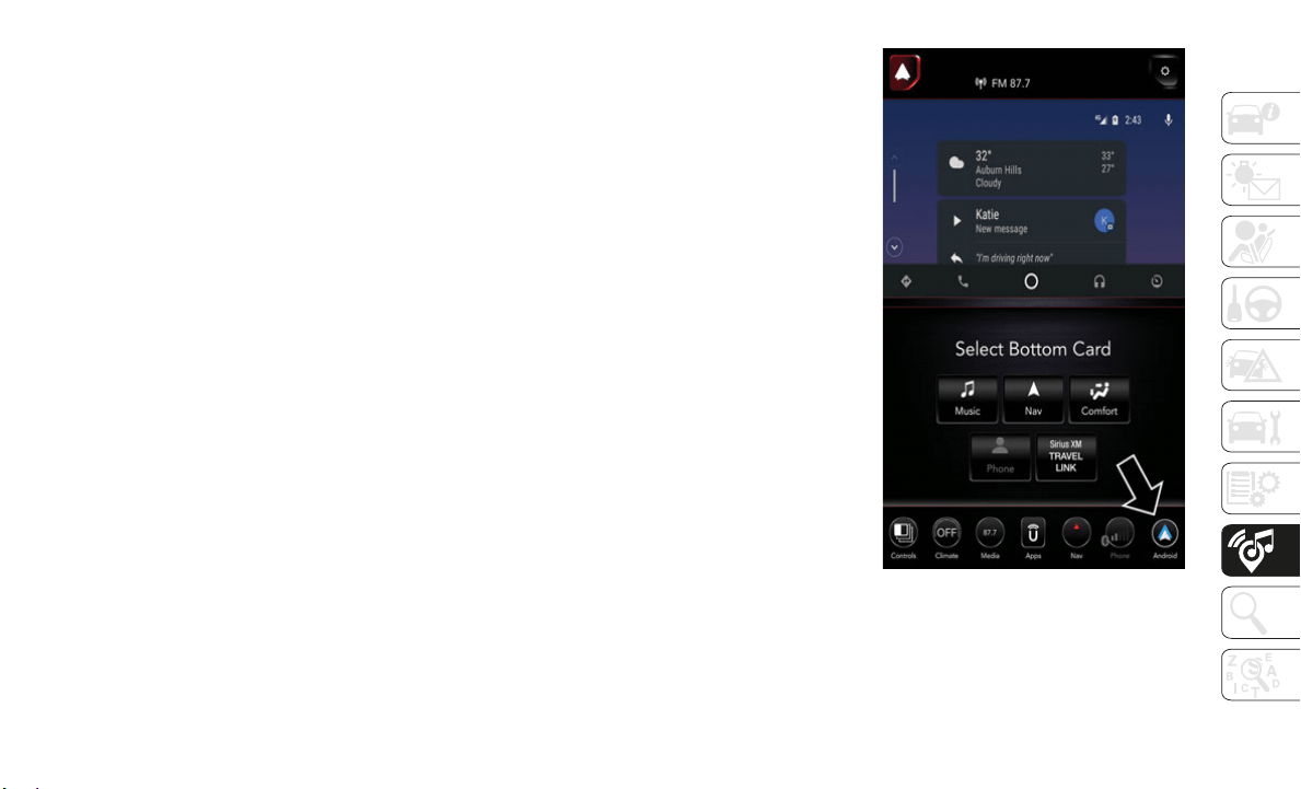
241
To store a radio preset manually, follow the
steps below:
1. Tune to the desired station.
2. Press
and hold the desired numbered
button o
n the touchscreen for more than
two seconds or until you hear a confirma
-
tion beep.
HD Radio — If Equipped
HD Radio operates similar to conventional
radio except it allows broadcasters to
transmit a high-quality digital signal.
With an HD radio receiver, the listener is
provided with a clear sound that enhances
the listening experience. HD radio can
also transmit data such as song title or
artist.
Android Auto — If Equipped
NOTE:
Feature availability depends on your carrier
and mobil
e phone manufacturer. Some
Android A
uto features may or may not be
available in every region and/or language.
Android Auto is a feature of your Uconnect
system, a
nd your Android 5.0 Lollipop, or
higher, powered smartphone with a data
plan, that allows you to project your smart
-
phone and a number of its apps onto the
touchscre
en radio display. Android Auto
automatically brings you useful information,
and organizes it into simple cards that
appear just when they are needed. Android
Auto can be used with Google's best-in-class
speech technology, the steering wheel
controls, the knobs and buttons on your radio
faceplate, and the radio display’s touch
-
screen to control many of your apps. To use
A
ndroid A
uto follow the following procedure:
1. Download the Android Auto app from the
Google P
lay store on your
Android-powered smartphone.
2. Connect your Android powered smart-
phone to
one of the media USB ports in
your vehi
cle. If the Android Auto app was
not downloaded, the first time you plug
your device in, the app will begin to
download.
NOTE:
Be sure to use the factory-provided USB
cable tha
t came with your phone, as after-
market cables may not work.
Uconnect 4C With 12–inch Display Android
Auto
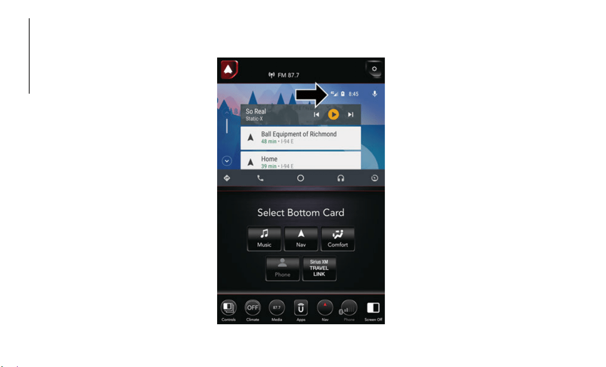
MULTIMEDIA
242
3. Once the device is connected, the system
displays the Android Auto home screen.
Android Auto should launch, but if not,
refer to the Uconnect Owner’s Manual
Supplement for the procedure to enable
the feature “AutoShow.” You can also
launch it by pressing Android Auto
located in the “Apps” menu. If you use
Android Auto frequently you can move
the app to the menu bar at the bottom of
the touchscreen. Press the “Apps”
button and locate the Android Auto app;
then press and drag the selected App to
replace an existing shortcut in the main
menu bar.
Once Android Auto is up and running on your
Uconnect
system, the following features can
be utilized using your smartphone’s data
plan:
Google Maps for navigation
Google Play Music, Spotify, iHeart Radio,
etc. for music
Handsfree Calling, and Texting for
communication
Hundred of compatible apps
NOTE:
To use Android Auto, make sure you are in an
area with
cellular coverage. Android Auto
may use cellular data and your cellular
coverage is shown in the upper right corner
of the radio screen.
Uconnect 4C NAV With 12–inch Display Google
Maps Data And Cellular Coverage
NOTE:
Requires compatible smartphone running
Android 5
.0 Lollipop or higher and download
app on Google Play. Android, Android Auto
and Google Play are trademarks of Google
Inc.
Maps
Push and hold the VR button on the steering
wheel or tap the microphone icon to ask
Google to take you to a desired destination by
voice. You can also touch the Navigation icon
in Android Auto to access Google Maps.
NOTE:
If the VR button is not held, and is only
p
ushed, t
he built-in Uconnect VR prompts
you and any navigation command said
launches the built-in Uconnect navigation
system.
While using Android Auto, Google Maps
provides
voice-guided:
Navigation
Live traffic information
Lane guidance
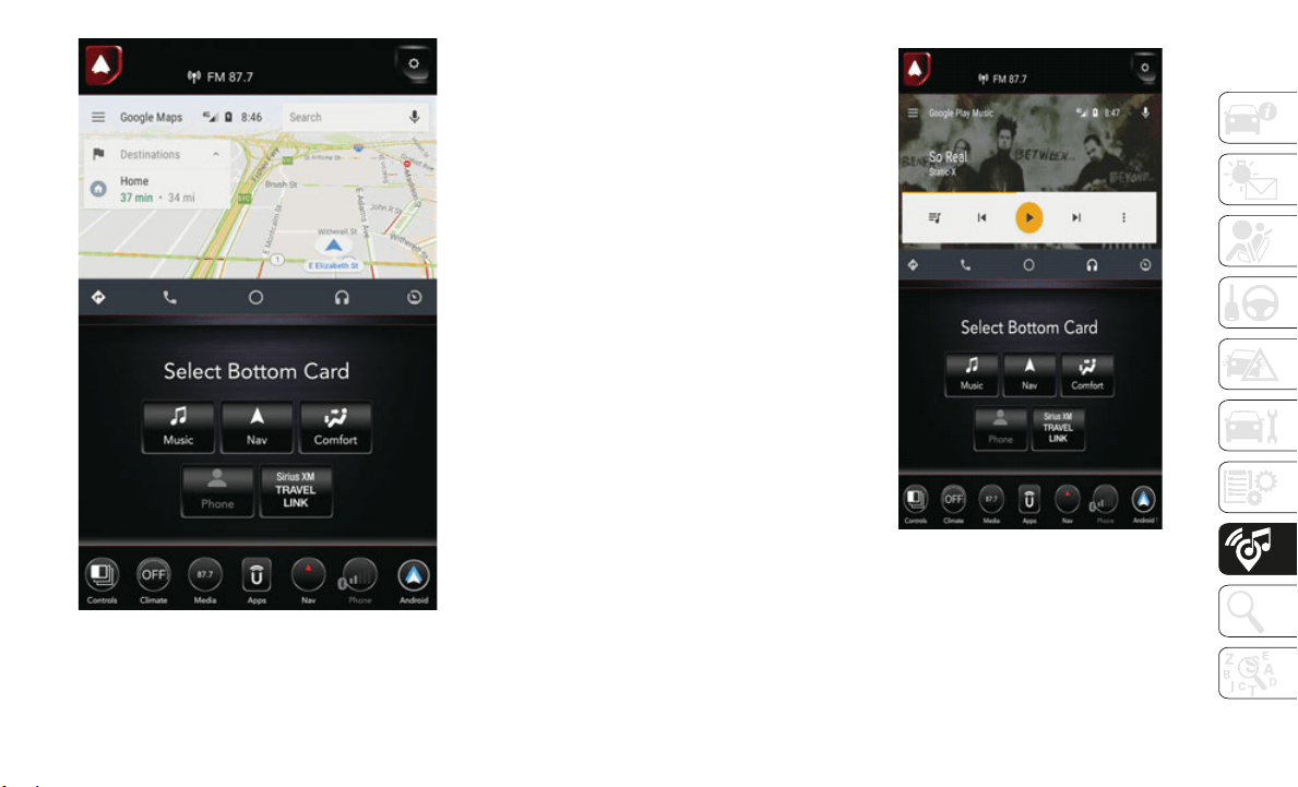
243
Google Maps
NOTE:
If you are using the built-in Uconnect naviga-
tion system, and you try and start a new route
u
sing the
Android Auto, via voice or any other
method, a pop-up appears asking if you
would like to switch from Uconnect naviga-
tion to smartphone navigation. A pop-up also
a
ppears,
asking if you’d like to switch, if
Android Auto is currently in use and you
attempt to launch a built-in Uconnect route.
Selecting “Yes” switches the navigation type
to the newly used method of navigation and
a route will be planned for the new destina
-
tion. If “No” is selected the navigation type
remains u
nchanged.
For further information, refer to
www.android.com/auto/.
For further information on the navigation
f
unction,
please refer to https://
support.google.com/android or https://
support.google.com/androidauto/.
Music
Android Auto allows you to access and
stream your favorite music with apps like
Google Play Music, iHeartRadio, and Spotify.
Using your smartphone’s data plan, you can
stream endless music on the road.
NOTE:
For Music apps, playlists, and stations to
f
unction
on your smartphone, it must be set
up prior to using Android Auto.
Android Auto Music
NOTE:
To see the metadata for the music playing
t
hrough A
ndroid Auto, select the Uconnect
System’s media screen.
For further information refer to https://
support.google.com/androidauto.
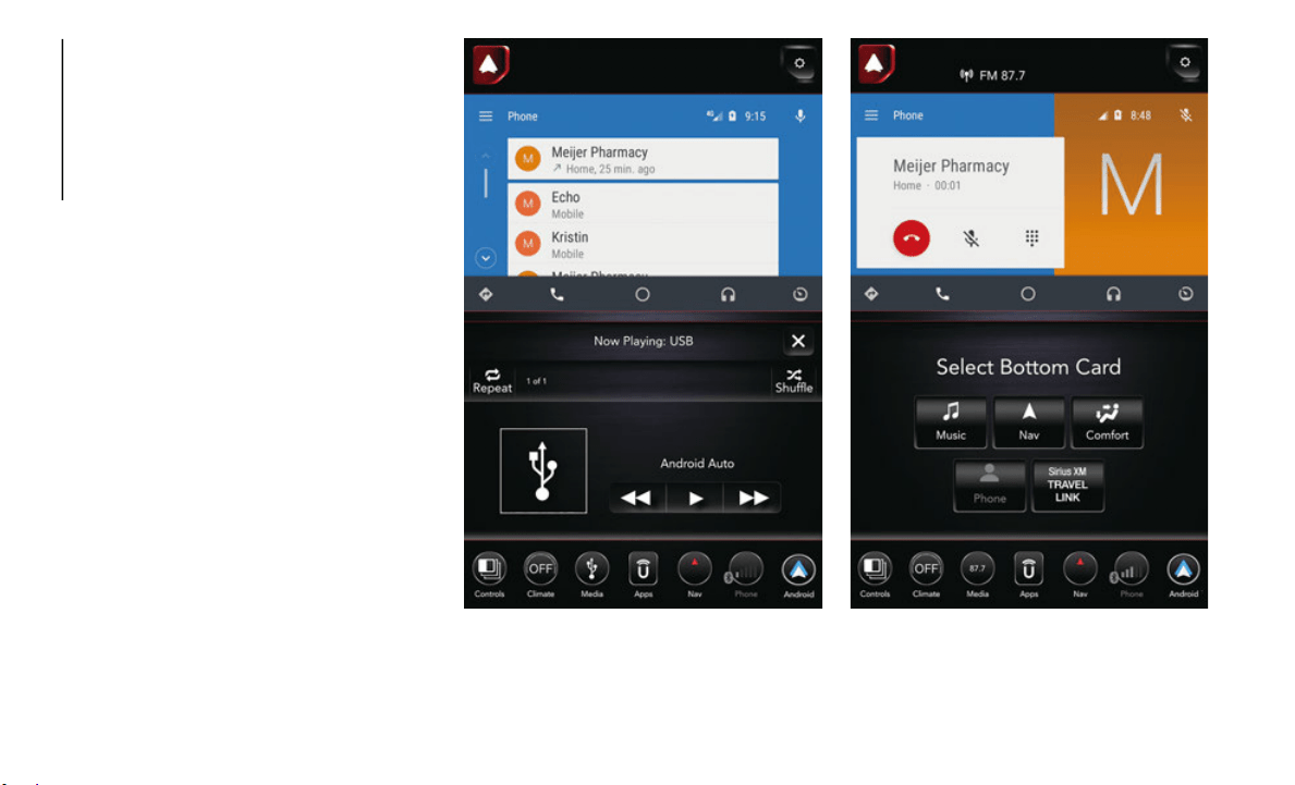
MULTIMEDIA
244
Communication
With Android Auto connected, press and
hold the VR button on the steering wheel to
activate voice recognition specific to the
Android Auto. This will allow you to send and
reply to text messages, have incoming text
messages read out loud, and place and
receive hands-free calls.
Android Auto Contact Android Auto Phone

245
Apps
The Android Auto App will display all the
compatible apps that are available to use
with Android Auto, every time it is launched.
You must have the compatible app down
-
loaded, and you must be signed in to the app
for it to
work with Android Auto. Refer to
g.co/androidauto to see the latest list of
available apps for Android Auto.
Apple CarPlay Integration — If Equipped
NOTE:
Feature availability depends on your carrier
and mobil
e phone manufacturer. Some
Apple Car
Play features may or may not be
available in every region and/or language.
Uconnect works seamlessly with Apple
CarPlay,
the smarter, more secure way to use
your iPhone in the car, and stay focused on
the road. Use your Uconnect Touchscreen
display, the vehicle's knobs and controls,
and your voice with Siri to get access to
Apple Music, Maps, Messages, and more.
To use CarPlay, make sure you are using
iPhone 5
or later, have Siri enabled in
Settings, ensure your iPhone is unlocked for
the very first connection only, and then use
the following procedure:
1. Connect your iPhone to one of the media
USB port
s in your vehicle.
NOTE:
Be sure to use the factory-provided Lightning
c
able tha
t came with your phone, as after-
market cables may not work.
2. O
nce the device is connected, the system
displays
the CarPlay home screen. Apple
CarPlay should launch, but if not, refer to
the Uconnect Owner’s Manual Supple
-
ment for the procedure to enable the
feature “
AutoShow.” You can also launch
it by pressing the CarPlay located in the
“Apps” menu. If you use Apple CarPlay
frequently you can move the app to the
menu bar at the bottom of the touch
-
screen. Press the “Apps” button and
l
ocate th
e CarPlay app; then press and
drag the selected App to replace an
existing shortcut in the main menu bar.
Uconnect 4C NAV With 12–inch Display
CarPlay
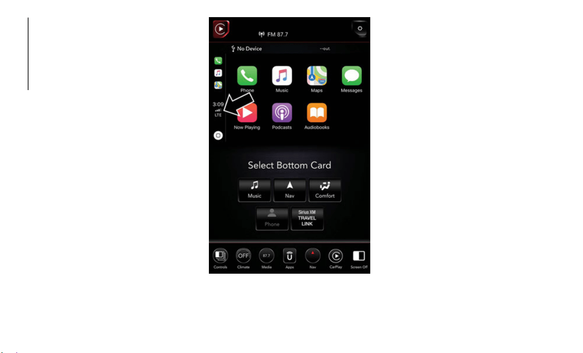
MULTIMEDIA
246
Once CarPlay is up and running on your
Uconnect system, the following features can
be utilized using your iPhone’s data plan:
Phone
Music
Messages
Maps
NOTE:
To use CarPlay make sure that cellular data
is turned
on, and that you are in an area with
cellular coverage. Your data and cellular
coverage is shown on the left side of the
radio screen.
Uconnect 4C NAV With 12–inch Display
CarPlay Data And Cellular Coverage
NOTE:
Requires compatible iPhone. See dealer for
p
hone com
patibility. Data plan rates apply.
Vehicle u
ser interface is a product of Apple.
Apple CarPlay is a trademark of Apple Inc.
i
Phone is
a trademark of Apple Inc., regis-
tered in the US and other countries. Apple
t
erms of
use and privacy statements apply.
Phone
With CarPlay, press and hold the VR button
on the steering wheel to activate a Siri voice
recognition session. You can also press and
hold the Home button within CarPlay to start
talking to Siri. This allows you to make calls
or listen to voice mail as you normally would
using Siri on your iPhone.
NOTE:
Only temporarily pushing the VR button on
the steer
ing wheel launches a built-in VR
session, not a Siri session, and it will not
function with CarPlay.
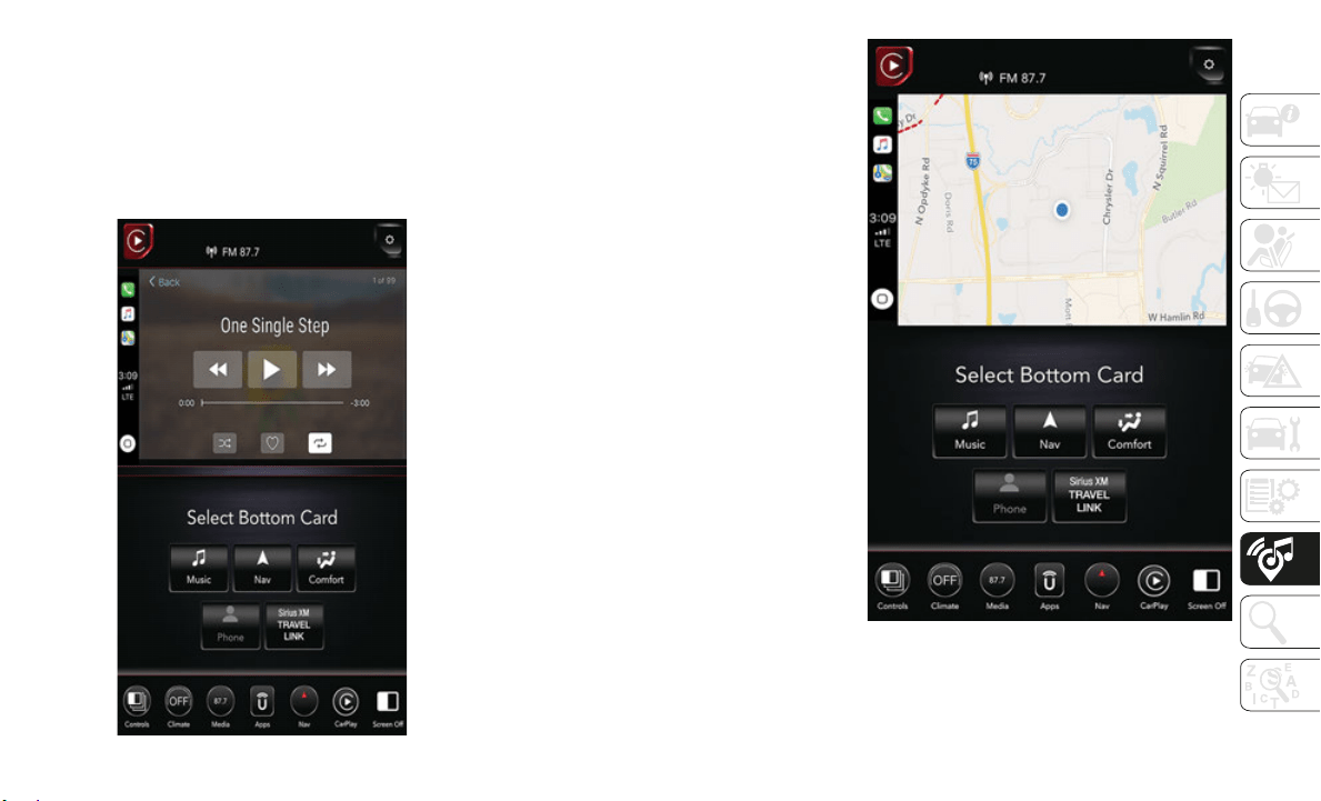
247
Music
CarPlay allows you to access all your artists,
playlists, and music from iTunes. Using your
iPhone’s data plan, you can also use select
third party audio apps including music,
news, sports, podcasts and more.
Apple Music
Messages
Just like Phone, CarPlay allows you to use
Siri to send or reply to text messages. Siri
can also read incoming text messages, but
driver’s will not be able to read messages, as
everything is done via voice.
Maps
To use your Apple Maps for navigation on
your Uconnect system, launch CarPlay, and
push and hold the VR button on the steering
wheel to use Siri to set your desired destina
-
tion. Alternatively, choose a nearby destina-
tion by pressing Destinations and selecting a
category,
by launching Siri from the destina-
tions page, or even by typing in a destination.
Maps
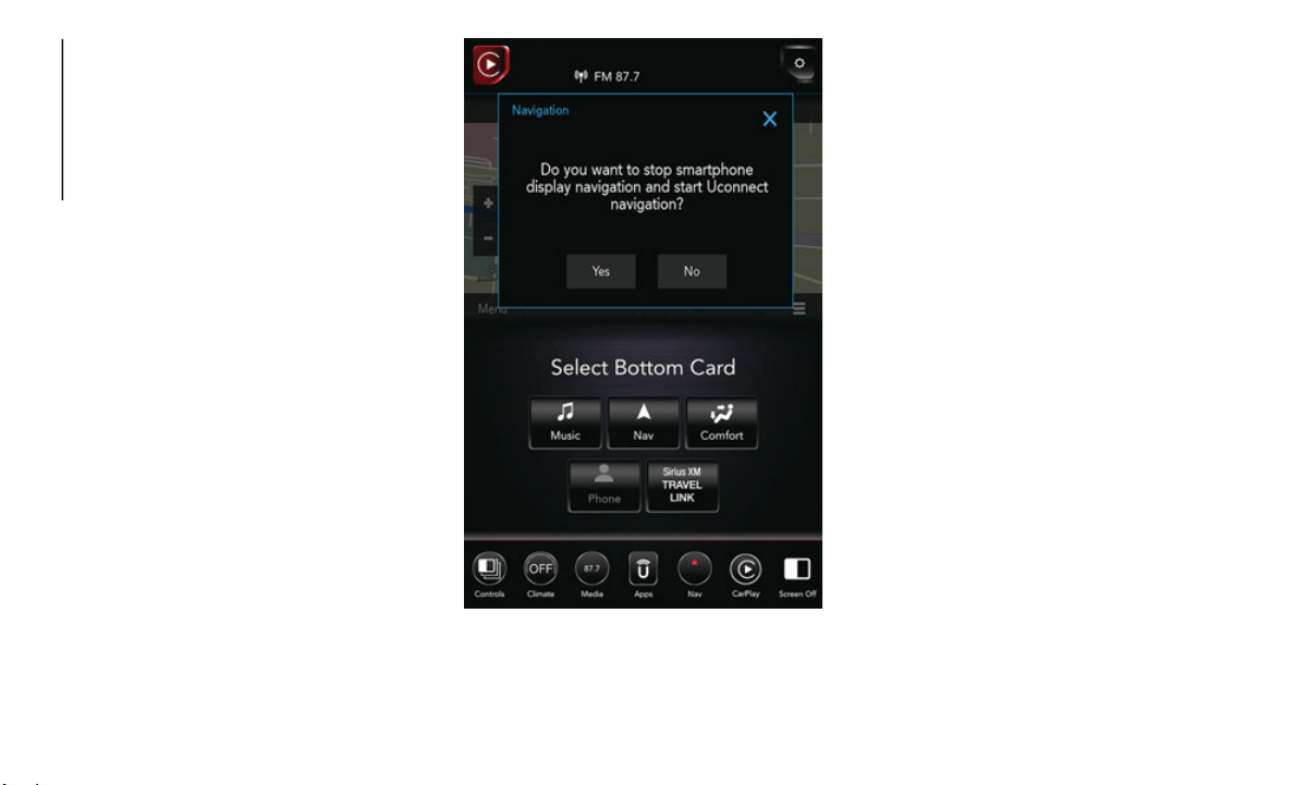
MULTIMEDIA
248
NOTE:
If the VR button is not held, and is only
pushed, the built-in Uconnect VR prompts
you and any navigation command said
launches the built-in Uconnect navigation
system.
If you are using the built-in Uconnect
navigation system, and you try and start a
new route using CarPlay, via voice or any
other method, a pop-up appears asking if
you would like to switch from Uconnect
navigation to iPhone navigation. A pop-up
also appears, asking if you’d like to switch,
if an CarPlay navigation is currently in use
and you attempt to launch a built-in Ucon
-
nect route. Selecting “Yes” switches the
n
avigatio
n type to the newly used method
of navigation and a route will be planned
for the new destination. If “No” is selected
the navigation type remains unchanged.
Navigation Pop-Up
Apps
To use a compatible app with CarPlay, you
must have the compatible app downloaded,
and you must be signed in to the app. Refer
to
http://www.apple.com/ios/carplay/ (U.S.
Residents) or https://www.apple.com/ca
(Canadian Residents) to see the latest list of
available apps for CarPlay.
UCONNECT SETTINGS
The Uconnect system allows you to access
Customer Programmable feature settings
such as Language, Display, Units, Voice,
Clock, Safety & Driving Assistance, Lights,
Doors & Locks, Auto-On Comfort, Engine Off
Options, Audio, Phone/Bluetooth, SiriusXM
Setup, Restore Settings, Clear Personal
Data, and System Information through
buttons on the touchscreen.
Push the SETTINGS button (Uconnect 3
With 5–in
ch Display), or press the “Apps”
button (on the Uconnect 4C/4C NAV With
8.4–inch Display or the Uconnect 4C NAV
With 12–inch Display) located near the
bottom of the touchscreen, then press the
“Settings” button on the touchscreen to
access the Settings screen. When making a
selection, scroll up or down until the
preferred setting is highlighted, then press
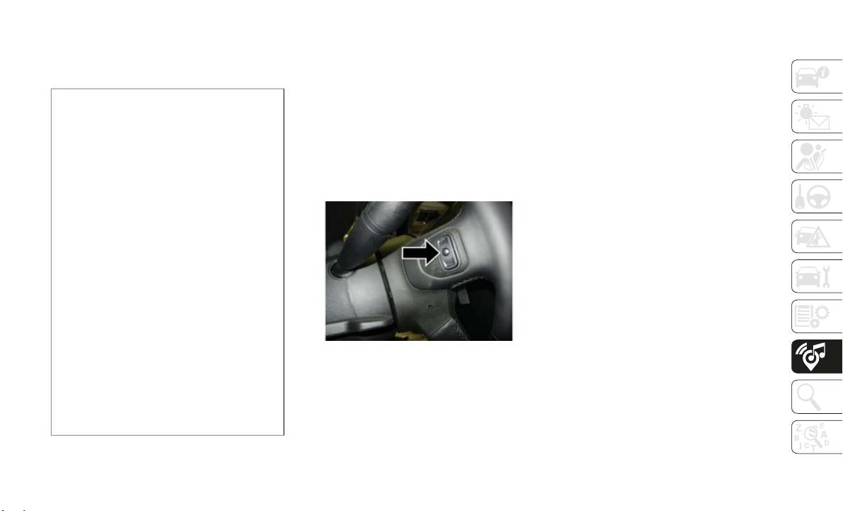
249
the preferred setting until a check-mark
appears next to the setting, showing that
setting has been selected. The following
feature settings are available:
NOTE:
Depending on the vehicles options, feature
settings m
ay vary.
Refer to “Uconnect Settings” in “Multi-
media” in the Owner’s Manual for further
informatio
n.
TIPS CONTROLS AND
GENERAL INFORMATION
Steering Wheel Audio Controls
The steering wheel audio controls are located
on the rear surface of the steering wheel.
Steering Wheel Audio Controls
Left Switch
Push the switch up or down to search for
the next listenable station.
Push the button in the center to select the
next preset radio station.
Right Switch
Push the switch up or down to increase or
decrease the volume.
Push the button in the center to change
modes AM/FM/SXM.
Reception Conditions
Reception conditions change constantly
while driving. Reception may be interfered
with by the presence of mountains, buildings
or bridges, especially when you are far away
from the broadcaster.
The volume may be increased when receiving
traffic al
erts and news.
Care And Maintenance
Observe the following precautions to ensure
the system is fully operational:
The display lens should not come into
contact with pointed or rigid objects which
could damage its surface; use a soft, dry,
anti-static cloth to clean and do not press.
Never use alcohol, gas and derivatives to
clean the display lens.
Prevent any liquid from entering the
system; this could damage it beyond
repair.
• Language — If
Equipped
• En
gine Off
Options
• Display • Suspension
• Units • Trailer Brake
• Voice • Audio
• Clock • Phone/Bluetooth
• Safety & Driving
A
ssistance
•
SiriusXM Setup
• Mirrors And
Wipers — I
f
Equipped
• Restore Settings
• Brakes • Clear Personal
Data
• Light
s • System
Informatio
n
• Doors & Locks
• Power Side Steps
—
If Equip
ped
• Auto-On Comfort
& Remote S
tart — If
Equipped

MULTIMEDIA
250
Anti-Theft Protection
The system is equipped with an anti-theft
protection system based on the exchange of
information with the electronic control unit
(Body Computer) on the vehicle. This guar
-
antees maximum safety.
If the check has a positive outcome, the
system wi
ll start to operate. See an autho-
rized dealer for further information.
SIRIUSXM GUARDIAN — IF
EQUIPPED
SiriusXM Guardian — If Equipped
(Available on Uconnect 4C/4C NAV With
8.4–inch or 12–inch Display)
NOTE:
Your vehicle may be transmitting data as
authorize
d by the subscriber.
SiriusXM Guardian enhances your ownership
and drivi
ng experience. When connected to
an operable network, you can:
Place a SOS Call to a SiriusXM Guardian
operator who can connect you to emer-
gency responders.
Remotely lock/unlock your doors and start
your vehicle from virtually anywhere, using
the Uconnect App from your device. You
can also do so by logging into your owner
site, or by calling SiriusXM Guardian Care
when your vehicle has an operable network
connection. Services can only be used
where coverage is available.
Receive text or email notifications if your
vehicle's security alarm goes off.
Receive stolen vehicle assistance, using
GPS technology to help authorities locate
your vehicle if it is stolen.
Get operator assistance using the ASSIST
button on your interior rearview mirror.
Before you drive, familiarize yourself with the
easy-to-u
se SiriusXM Guardian services.
1. The ASSIST and SOS Call buttons are
located
on your rearview mirror. The
ASSIST button is used for contacting
Roadside Assistance, Vehicle Care, Siri
-
usXM Guardian Care, and Uconnect
Care. The
SOS Call button connects you
to a SiriusXM Guardian Care Agent, who
can connect you to emergency services.
2. The Uconnect “Apps ” button is
located in the center of the menu bar of
the radio
touchscreen. This is where you
can manage your Apps.
3. The Uconnect Voice Command and
Uconnect
Phone buttons are located on
the left side of your steering wheel. These
buttons let you use your voice to give
commands, make phone calls, send and
receive text messages,, enter navigation
destinations, and control your radio and
media devices.
WARNING!
ALWAYS obey traffic laws and pay
attention to the road. ALWAYS drive safely
with your hands on the steering wheel. You
have full responsibility and assume all
risks related to the use of the features and
applications in this vehicle. Only use the
features and applications when it is safe to
do so. Failure to do so may result in an
accident involving serious injury or death.

251
Included Trial Period For New Vehicles
Your new vehicle may come with an included
trial per
iod for use of the SiriusXM Guardian
services starting at the date of vehicle
purchase (date based on vehicle sales notifi
-
cation from your dealer). To activa
te the trial,
you must first register with SiriusXM Guardian.
After the trial period, if you wish to continue
your SiriusXM Guardian services you can
choose to purchase a subscription.
SiriusXM Guardian Activation
To unlock the full potential of SiriusXM
Guardian in your vehicle, you must activate
your SiriusXM Guardian services.
1. Press the Apps icon on the bottom of your
in-vehic
le touchscreen.
2. Select the Activate Services icon from
your lis
t of apps.
3. Select “Customer Care” to speak with a
SiriusXM
Guardian Customer Care agent
who will activate services in your vehicle,
or select “Enter Email” to activate on the
web.
Why sign up for SiriusXM Guardian? Here are
j
ust a few examples of things you’ll be able
to do:
Know that help, if you need it, is only a
button press away with Assist.
Lock and unlock your vehicle doors from
hundreds of miles away.
Find your vehicle, no matter where you
parked, using the convenient Vehicle
Finder function.
Use Send & Go to send a navigation route
from your mobile phone to your vehicle’s
navigation system.
For further information:.
U.S. residents visit: www.siriusxm.com/
guardian
Canadian residents visit: www.siri-
usxm.ca/guardian
Download The Uconnect App
You’re only a few steps away from using
remote commands and other valuable
services.
Mobile App
To use the Uconnect App:
Search for and download the Uconnect
App from the store on your compatible
iPhone or Android powered device.
Log in to the app using the email address
and password you created when you acti-
vated the services.
Press the “Remote” button on the bottom
menu bar of the app to Lock/Unlock,
Remote Start (if equipped), and activate
your horn and lights remotely.

MULTIMEDIA
252
(Continued)
(Continued)
Press the “Location” button on the bottom
menu bar of the app to bring up a map to
locate your vehicle or send a location to
your vehicle’s navigation system.
Press the menu button (three horizontal
lines) in the upper left corner of the app to
access settings and support information.
Renewing Subscriptions (Uconnect 4C/4C
NAV With 8.4-inch or 12-inch Display)
Subscriptions can be purchased online by
logging into your owner account. If you need
help push the ASSIST button on the rearview
mirror, then select SiriusXM Guardian Care
or:
U.S. residents dial:
1-844-796-4827
Canadian residents dial:
1-877-324-9091
Maintaining Your SiriusXM Guardian
Account
Selling Your Vehicle
When you sell your vehicle, we recommend
that you
remove your SiriusXM Guardian
Account information from the vehicle. You
can do this by pressing the ASSIST button in
your vehicle and selecting SiriusXM
Guardian, or call:
U.S. residents dial:
1-844-796-4827
Canadian residents dial:
1-877-324-9091
Built-In Features
WARNING!
ALWAYS drive safely with your hands on
the wheel. You have full responsibility and
assume all risks related to the use of the
Uconnect features, SiriusXM Guardian
services, and applications in this vehicle.
Only use Uconnect features and SiriusXM
Guardian services when it is safe to do so.
Failure to do so may result in an accident
involving serious injury or death.
WARNING!
ALWAYS obey traffic laws and pay atten-
tion to the road. Some features are
limited w
hile the vehicle is in motion.
Some services, including SOS, will NOT
work without a subscription and an oper
-
able network connection.
Ignoring the rearview mirror light could
mean you may not have SOS Call service
if needed. If the rearview mirror light is
illuminated, have an authorized dealer
service the SOS Call system immedi
-
ately.
The Occupant Restraint Controller (ORC)
turns on the Air Bag Warning Light on
the instrument panel if a malfunction is
detected in any part of the airbag
system. If the Air Bag Warning Light is
illuminated, the air bag system may not
be working properly and the SOS Call
system may not send a signal to a SOS
Call operator if an air bag is deployed. If
the Air Bag Warning Light is illuminated,
have an authorized dealer service your
vehicle immediately.
If anyone in the vehicle could be in
danger (e.g., fire or smoke is visible,
dangerous road conditions or location),
do not wait for voice contact from a SOS
Call operator. All occupants should exit
the vehicle immediately and move to a
safe location.
WARNING! (Continued)
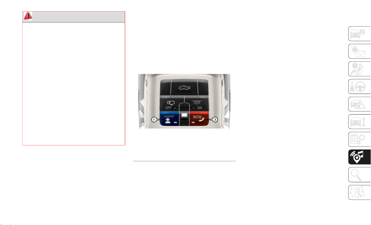
253
NOTE:
Your vehicle may be transmitting data as
authorize
d by the subscriber.
1. ASSIST Call (4C/4C NAV With 8.4–inch
Display
and Uconnect 4C NAV With 12–inch
Display) — The overhead console contains
an ASSIST button, allowing you to speak to
a call center agent for support:
Assist And SOS
Roadside Assistance Call — If you get a
flat tire, or need a tow, you’ll be
connected to someone who can help
anytime. Additional fees may apply.
Additional information in this section.
Uconnect Care — In vehicle support for
Uconnect Apps and Features.
SiriusXM Guardian Care — In vehicle
support for SiriusXM Guardian services.
Vehicle Care — Total support for your
FCA US LLC vehicle.
NOTE:
In order to provide SiriusXM Guardian Services
to you, w
e may record and monitor your conver-
sations with Roadside Assistance, Uconnect
C
are, Sir
iusXM Guardian Care, or Vehicle Care,
whether such conversations are initiated
through the SiriusXM Guardian services in your
vehicle, your device, or via a landline device,
and may share information obtained through
such recording and monitoring in accordance
with regulatory requirements. You acknowl
-
edge, agree, and consent to any recording,
m
onitorin
g or sharing of information obtained
through any such call recordings.
2. Emergency SOS Call (If Equipped) — The
ove
rhead console contains a SOS Call
button that, when pressed, may place a
call from your vehicle to a SiriusXM
Guardian Care operator, who can connect
you to emergency service operators, to
request help from local police, fire or
ambulance personnel. If this button is
accidentally pressed, you will have ten
seconds to stop the call. To cancel, press
The SOS Call system is embedded into
the vehicle’s electrical system. Do not
add aftermarket electrical equipment to
the vehicle’s electrical system. This may
prevent your vehicle from sending a
signal to initiate an emergency call. To
avoid interference that can cause the
SOS Call system to fail, never add after
-
market equipment (e.g., two-way mobile
radio, CB
radio, data recorder, etc.) to
your vehicle’s electrical system or modify
the antennas on your vehicle.
IF YOUR VEHICLE LOSES BATTERY
POWER FOR ANY REASON
(INCLUDING DURING OR AFTER AN
ACCIDENT), the Uconnect features,
apps, and SiriusXM Guardian services,
among others, will not operate.
WARNING! (Continued)
1 — ASSIST Button
2 — SOS Button

MULTIMEDIA
254
the SOS Call button again or press the
“Cancel” button shown on the touch-
screen. After ten seconds has passed, the
S
OS call
will be placed and only the SOS
Call operator can cancel it. The LED light
on the overhead console will turn green
once a connection to a SOS Call operator
has been made. The green LED light will
turn off once the SOS Call is terminated.
Have an authorized dealer service the
vehicle if the overhead console light is
continuously red. On equipped vehicles,
this feature requires a functioning elec
-
trical system, a subscription, and an
operable
network connection. If a connec-
tion is made between a SOS Call operator
a
nd your
vehicle, you understand and agree
that SOS Call operators will stay on the line,
even after you connect with emergency
services. The Emergency services operator
may, like any other emergency call, record
conversations and sounds in and near your
vehicle upon connection.
3. Theft Alarm Notification — The T
heft
Alarm Notification feature notifies you
via email or text (SMS) message when
the vehicle’s factory-installed security
alarm system has been set-off. There are
a number of reasons why your alarm may
have been triggered, one of which could
be that your vehicle was stolen. If so,
please see the details of the Stolen
Vehicle Assistance service below. When
you activate, Theft Alarm Notification is
automatically set to send you an email at
the email address you provide should the
alarm go off. You may also opt to have a
text message sent to your device.
4. Stolen Vehicle Assistance — If yo
ur
vehicle is stolen, contact local law
enforcement immediately to file a stolen
vehicle report. Once this report has been
filed, SiriusXM Guardian Care can help
locate your vehicle. The SiriusXM
Guardian Care agent will ask for the
stolen vehicle report number issued by
local law enforcement. As long as your
vehicle has a SiriusXM Guardian
subscription and an operable network
connection, the agent may be able to
locate the stolen vehicle and work with
law enforcement to help recover it. Your
vehicle must have an operable network
connection and must be registered with
SiriusXM Guardian with an active
subscription that includes the applicable
feature.
5. 4G Wi-Fi Hotspot — If Equipped — Allow
s
you and your passengers to connect their
portable devices to the built-in 4G Wi-Fi
capabilities of your Uconnect system.
Purchasing 4G Wi-Fi Hotspot requires
the use of an Internet-enabled portable
device.
NOTE:
Uconnect offers a complimentary 3–month
trial per
iod that includes 1GB of total data.
The trial can be activated any time within the
first year of new vehicle ownership.
a. To start, the Enable W
i-Fi Hotspot
should be un-checked.
b. Select the Wi-Fi Ho
tspot Setup option
from the toushcreeen to locate your
Hotspot Name and Password. Make
note of this information.
c. Tap the Back Arrow to return to the
main Wi-
Fi Hotspot page, then check
the box to Enable Wi-Fi Hotspot.
d. From your portable device Wi-Fi
settings
menu, select the Hotspot
Name from the list of available
networks and enter the provided Pass
-
word.

255
e. Open the web browser on your portable
device and enter the following web
address:
https://myvehicle.att.com/#/
login.
f. Create a myVehicle account or log in to
your exi
sting one.
g. Select and purchase the desired
subscrip
tion option. The Wi-Fi Hotspot
will activate after a few minutes.
For additional assistance, call AT&T Cus-
tomer Care at: 866-595-1
330.
NOTE:
Your vehicle must have a working electrical
s
ystem fo
r any of the in vehicle SiriusXM
Guardian services to operate.
SiriusXM Guardian Remote Features
If you own a compatible iPhone or Android
powered device, the Uconnect App allows
you to remotely lock or unlock your doors,
start your engine or activate your horn and
lights from virtually anywhere. Your vehicle
must be equipped with remote start, must
have a SiriusXM Guardian subscription, and
must have an operable network connection.
Services can only be used where coverage is
available. You can download the App from
Mopar Owner Connect or from the App Store
(iPhone) or Google Play Store (Android). Visit
UconnectPhone.com to determine if your
device is compatible. For Uconnect Phone
customer
support and to determine if your
device is compatible.
Please visit UconnectPhone.com or for U.S.
residents call 1-877-855
-8400.
Canadian residents call: 1-800-465
-2001
(English) or call:1-800-387-9983 (French).
Remote Start (If Equipped) — This f
eature
provides the ability to start the engine on
your vehicle, without the keys and from virtu
-
ally any distance. You can send a request to
your vehi
cle in one of two ways:
1. Using the Uconnect App from a compat-
ible dev
ice.
2. From the Mopar Owner Connect website.
After 15 minutes if you have not entered
your vehi cle with the key, the engine will
shut off automatically.
You can also send a command to turn-off
an engine that has been remote started.
This remote function requires your
vehicle to be equipped with a
factory-installed Remote Start system.
To utilize this feature after the Uconnect
App is downloaded, login with your user
name and password.
You will need your four digit SiriusXM
Guardian
Security PIN to confirm the
request. Press the “remote start” icon on
your Uconnect App to remotely start the
vehicle.
You can set-up notifications for your account
to receiv
e an email or text (SMS) message
every time a command is sent. Login to
Mopar Owner Connect at
mopar.com and
click on Edit Profile to manage SiriusXM
Guardian
Notifications.
Remote Door Lock/Unlock — If Equipped —
This fea
ture provides the ability to lock or
unlock the door on your vehicle, without the
keys and from virtually any distance. You can
send a request to your vehicle in one of three
ways:
1. Using the Uconnect App from a compat-
ible dev
ice.
2. From the Mopar Owner Connect website.
3. By con
tacting SiriusXM Guardian Care on
the phon
e.
To use this feature after the Uconnect App is
downloade
d, login using your user name and
password. You will need your four digit Siri
-
usXM Guardian Security PIN to confirm the

MULTIMEDIA
256
request. Press the “closed lock” icon on your
Uconnect App to lock the doors, and press
the “open lock” icon to unlock the driver’s
door.
You can set-up notifications for your account
to receiv
e an email or text (SMS) message
every time a command is sent. Login to
Mopar Owner Connect at
mopar.com and
click on Edit Profile to manage SiriusXM
Guardian
Notifications.
Remote Horn And Lights — If Equipped — It’s
eas
y to locate a vehicle in a dark, crowded or
noisy parking area by activating the horn and
lights. It may also help if you need to draw
attention to your vehicle for any reason. You
can send a request to your vehicle in one of
three ways:
1. Using the Uconnect App from a compat-
ible dev
ice.
2. From the Mopar Owner Connect website.
3. By con
tacting the SiriusXM Guardian
Care on
the phone.
To use this feature after the Uconnect App is
downloade
d, login using your user name and
password. You will need your four digit Siri
-
usXM Guardian Security PIN to confirm the
request.
You can set-up notifications for your
account to receive an email or text (SMS)
message every time a command is sent.
Login to Mopar Owner Connect at mopar.com
and click on Edit Profile to manage SiriusXM
Guardian Notifications.
Vehicle Finder—If Equipped
The Vehicle Finder feature of the Uconnect
Mobile App allows you to find the location of
your vehicle when you can't remember where
it's parked. You can also sound the alarm and
flash the lights to make finding your vehicle
even easier.
To find your vehicle:
1. Press the “Location” tab on the Ucon-
nect Mob
ile App bottom bar.
2. Select the “Vehicle” icon to determine
the loca
tion of your vehicle.
3. Select the “Find Route” button that
appears,
once your vehicle is located.
4. Select your preferred Navigation App to
route a
path to your vehicle.
Send & Go
The Send & Go feature of the Uconnect
Mobile App allows you to search for a desti-
nation on your mobile device and then send
t
he route
to your vehicle’s Uconnect Naviga-
tion system.
To send a navigation route to your vehicle:
1. P
ress the “Location” tab on the Ucon-
nect Mob
ile App bottom bar.
2. Either type in the destination you would
like to
navigate to, or search through one
of the categories provided.
3. Select the destination you want to route
to from
the list that appears.
4. Press the “Send To Vehicle” button, and
then con
firm the destination by pressing
“Yes,” to send the navigation route to the
Uconnect Navigation in your vehicle.
5. Finally, confirm the route inside your
vehicle
by pressing the “Go Now” option
on the pop-up that appears on the touch
-
screen, when the vehicle is started.
IPOD/USB/MEDIA PLAYER
CONTROL
There are many ways to play music from MP3
players, or USB devices through your
vehicle's sound system. Press your Media
button on the touchscreen to begin.
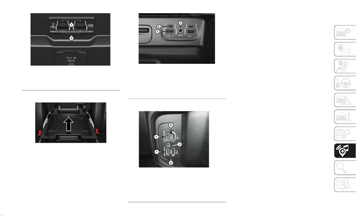
257
Rear Center Console USB Ports
Center Console USB Port
Center Stack USB/AUX Media Hub
Center Console USB/AUX Media Hub
Audio Jack (AUX)
The AUX allows a device to be plugged
into the radio and utilize the vehicle’s
sound system, using a 3.5
mm audio
cable, to
amplify the source and play
through the vehicle speakers.
Pressing the “AUX” button on the touch-
screen will change the mode to auxiliary
device if
the audio jack is connected,
allowing the music from your device to be
heard through the vehicle's speakers. To
activate the AUX, plug in the audio jack.
The functions of the device are controlled
using the device buttons. The volume may
be controlled using the radio or device.
USB Port
Connect your compatible device using a
USB cable into the USB Port. USB
Memory sticks with audio files can also be
used. Audio from the device can be played
on the vehicles sound system while
providing metadata (artist, track title,
album, etc.) information on the radio
display.
1 — Mini USB (Type C) Ports
2 — Standard USB (Type A) Ports
1 — Standard USB (Type A) Port #1
2 — Mini USB (Type C) Port
3 — AUX Port
1 — Standard USB (Type A) Ports
2 — Mini-USB (Type C) Ports
3 — AUX Port

MULTIMEDIA
258
When connected, the compatible USB
device can be controlled using the radio or
Steering Wheel Audio Controls to play,
skip to the next or previous track, browse,
and list the contents.
The battery charges when plugged into the
USB port (if supported by the specific
device).
To route the USB cable out of the center
console, use the access cut out.
NOTE:
When connecting your device for the first
t
ime, the
system may take several minutes to
read your music, depending on the number
of files. For example, the system will take
approximately five minutes for every 1,000
songs loaded on the device. Also during the
reading process, the Shuffle and Browse
functions will be disabled. This process is
needed to ensure the full use of your features
and only happens the first time it is
connected. After the first time, the reading
process of your device will take considerably
less time unless changes are made or new
songs are added to the playlist.
Bluetooth Streaming Audio
If using a Bluetooth equipped device you
may also be able to stream music to your
vehicle's sound system. Your connected
device must be Bluetooth compatible and
paired with your system (see Uconnect
Phone for pairing instructions). You can
access the music from your connected Blue
-
tooth device by pressing the Bluetooth
button on
the touchscreen while in Media
mode.
NAVIGATION
The information in the section below is
only applicable if you have the Uconnect
4C NAV With 8.4–inch Display system or
the Uconnect 4C NAV With 12–inch
Display system.
Press the “Nav” button on the touchscreen
in the me
nu bar to access the Navigation
system.
Changing The Navigation Voice Prompt
Volume
Changing The Navigation Voice Prompt Volume
1. Press the “Settings” button on the touch-
screen i
n the lower right area of the
screen.
2. I
n the Settings menu, press the “Guid-
ance” bu
tton on the touchscreen.
3. I
n the Guidance menu, adjust the Nav
Volume b
y pressing the “+” or “–”
buttons on the touchscreen.
Uconnect 4C NAV With 8.4–inch Display
Navigation
1 — Search For A Destination In All Categories
2 — Find A Destination
3 — View Map
4 — Navigate To Saved Home Destination
5 — Navigate To Saved Work Destination
6 — Navigation Settings
7 — Emergency
8 — Information
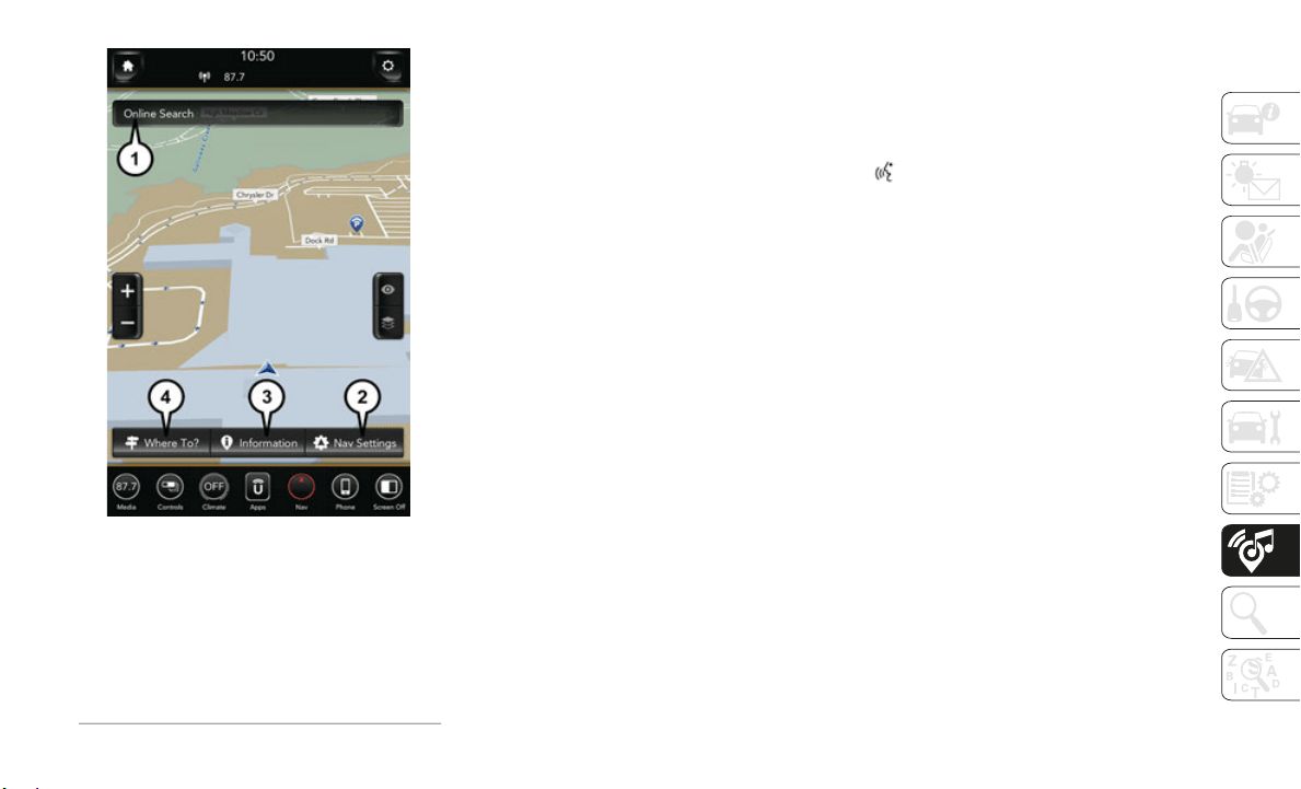
259
Uconnect 4C NAV With 12–inch Display
Navigation
Finding Points Of Interest
From the main Navigation menu, press the
“Where To?” button on the touchscreen,
then press the “Points of Interest” button
on the touchscreen.
Select a category and then a subcategory,
if necessary.
Select your destination and press the
“GO!” button on the touchscreen.
Finding A Place By Spelling The Name
From the Main Navigation Menu press the
“Where to?” button on the touchscreen,
press the “Points of Interest” button on
the touchscreen, then press the “Spell
Name” button on the touchscreen.
Enter the name of your destination.
Press the “List” button on the touch-
screen.
Select your destination and press the
“GO!” button on the touchscreen.
One-Step Voice Destination Entry
Enter a navigation destination without
taking your hands off the wheel.
Just push the Uconnect Voice Command
button on the steering wheel, wait for
the beep and say something like, "Find
Addres
s 800 Chrysler Drive Auburn Hills
MI."
NOTE:
Destination entry is not available while your
vehicle i
s in motion. However, you can also
use Voice Commands to enter an address
while moving.
NOTE:
Refer to “Uconnect Voice Recognition Quick
Tips” in
this section for further information.
Setting Your Home Location
To add a Home location, press the “Nav”
button on the touchscreen in the menu bar
to access the Navigation system and the
Main Navigation menu.
1 — Search For A Destination In All
Categorie
s
2 — Navigation Settings
3 — Information
4 — Find A Destination
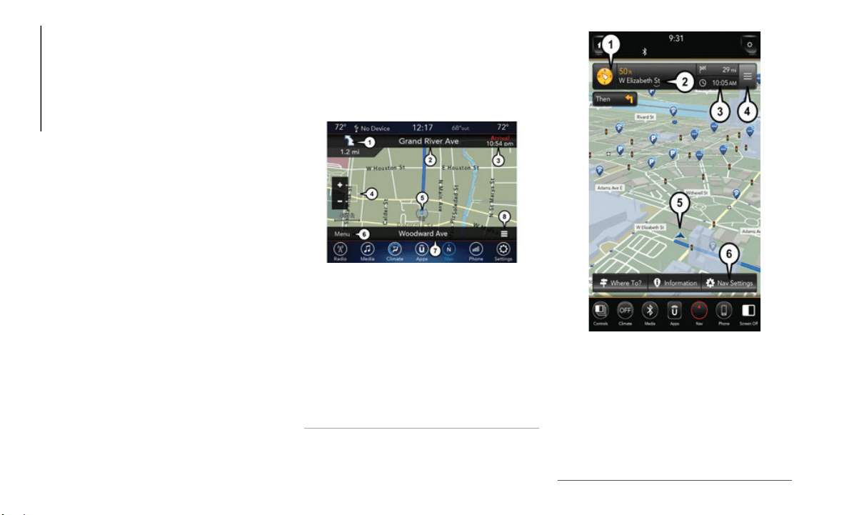
MULTIMEDIA
260
Press the “Home” button on the touch-
screen. You can add a Home location by
either se
lecting “Spell City,” “Spell
Street,” or “Select Country.” Select
County is automatically filled out based on
your state.
Once you have entered your Home loca-
tion, select the “Save Home” button
located o
n the lower left-hand side of your
touchscreen.
To delete a saved Home location (or other
saved locations), so you can save a new
Home location, press the “Nav” button on
the touchscreen, and in the “Where To”
screen, press “Edit Where To” and then
press the “Home” button on the touch
-
screen. Under the Manage screen press
t
he “Rese
t Location” button. A confirma-
tion screen will appear asking if you “Are
y
ou sure
you want to reset this location?”
Press “Reset” to confirm the deletion. Set
a new Home location by following the
previous instructions.
Home
A Home location must be saved in the
system. From the Main Navigation menu,
press the “Home” button on the touch
-
screen.
Uconnect 4C/4C NAV Map
Uconnect 4C NAV Map
1 — Distance To Next Turn
2 — Next Turn Street
3 — Estimated Time Of Arrival
4 — Zoom In And Out
5 — Your Location On The Map
6 — Navigation Main Menu
7 — Current Street Location
8 — Navigation Routing Options
1 — Compass
2 — Distance To Next Turn And Next Turn
Street
3 — Estimated Time Of Arrival
4 — Navigation Routing Options
5 — Your Location On The Map
6 — Navigation Main Menu

261
Your route is marked with a blue line on the
map. If you depart from the original route,
your route is recalculated. A speed limit icon
could appear as you travel on major road
-
ways.
Adding A Stop
To add a stop you must be navigating a
route.
Press the “Menu” button on the touchscreen
to return to the Main Navigation menu.
Press the “Where To?” button on the touch-
screen, then search for the extra stop. When
another l
ocation has been selected, you can
choose to cancel your previous route, add as
the first destination or add as the last desti
-
nation.
Press the desired selection and press the
“GO!” button on the touchscreen.
Taking A Detour
To take a detour you must be navigating a
route.
Press the “Detour” button on the touch-
screen.
NOTE:
If the route you are currently taking is the only
r
easonabl
e option, the device may not calcu-
late a detour. For more information, see your
Uconnect
Owner's Manual Supplement.
SiriusXM Traffic Plus (4C NAV With
8.4–inch And 12–inch Display)
Don't Drive Through Traffic. Drive Around It.
Avoid congestion before you reach it. By
enhancing
your vehicle's navigation system
with the ability to see detailed traffic informa
-
tion, you can pinpoint traffic incidents, deter-
mine average traffic speed and estimate travel
t
ime alon
g your route. Since the service is inte-
grated with a vehicle's navigation system, Siri-
usXM Traffic Plus can help drivers pick the
f
astest r
oute based on traffic conditions.
Detailed information on traffic speed, acci-
dents, construction, and road closings.
Traffic information from multiple sources,
including police and emergency services,
cameras and road sensors.
Coast-to-coast delivery of traffic information.
View conditions for points along your route
and beyond. Available in over 130 markets.
SiriusXM Travel Link (4C NAV With
8.4–inch And 12–inch Display)
In addition to delivering over 130 channels of
the best sports, entertainment, talk, and
commercial-free music, SiriusXM offers
premium data services that work in conjunction
with compatible navigation systems. SiriusXM
Travel Link brings a wealth of useful informa
-
tion into your vehicle and right to your finger-
tips.
Fuel Prices — Check local fuel prices in your
area and route to the station of your choice.
Movie Listings — Check local movie theatres
and listings in your area and route to the
theater of your choice.
Sports Scores — In-game and final scores as
well as weekly schedules.
Weather — Check variety of local and
national weather information from radar
maps to current and 5-day forecast.
SiriusXM Travel Link feature is completely inte-
grated into your vehicle. A few minutes after
y
ou start
your vehicle, Travel Link information
arrives and updates in the background. You can
access the information whenever you like, with
no waiting.
To access SiriusXM Travel Link, press “Apps”
button on
the touchscreen, then press the
“SiriusXM Travel Link” button on the touch
-
screen.
NOTE:
SiriusXM Travel Link requires a subscription,
sold separately after the trial subscription
included with your vehicle purchase.
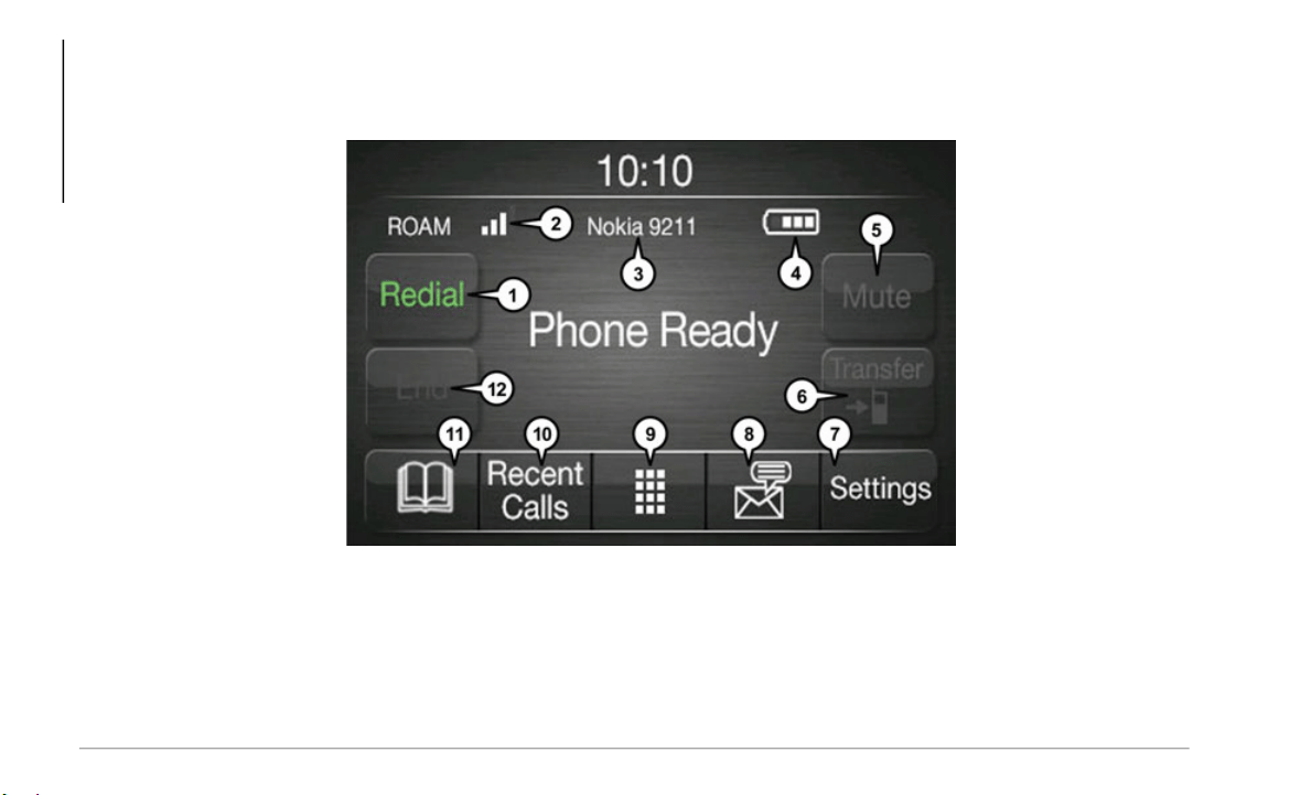
MULTIMEDIA
262
UCONNECT PHONE
Uconnect Phone (Bluetooth Hands Free Calling)
Uconnect 3 With 5–inch Display Radio Phone Menu
1 — Call/Redial/Hold 7 — Uconnect Phone Settings Menu
2 — Mobile Phone Signal Strength 8 — Text Messaging
3 — Currently Paired Mobile Phone 9 — Direct Dial Pad
4 — Mobile Phone Battery Life 10 — Recent Call Log
5 — Mute Microphone 11 — Browse Phone Book
6 — Transfer To/From Uconnect System 12 — End Call
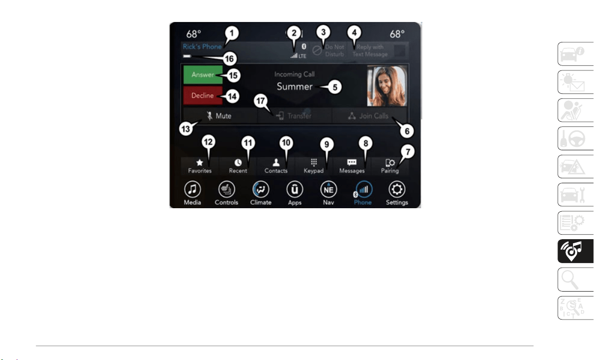
263
Uconnect 4C/4C NAV With 8.4–inch Display Phone Menu
1 — Currently Paired Mobile Phone 11 — Recent Call Log
2 — Mobile Phone Signal Strength 12 — Favorite Contacts
3 — Do Not Disturb 13 — Mute Microphone
4 — Reply with Text Message 14 — Decline Incoming Call
5 — Current Phone Contact’s Name 15 — Answer/Redial/Hold
6 — Conference Call* 16 — Mobile Phone Battery Life
7 — Phone Pairing 17 — Transfer To/From Uconnect System
8 — Text Messaging Menu** * — Conference call feature only available on GSM mobile devices
9 — Direct Dial Pad ** — Text messaging feature not available on all mobile phones
10 — Contact Menu (requires Bluetooth MAP profile)
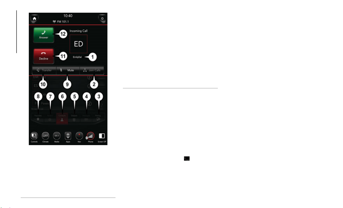
MULTIMEDIA
264
Uconnect 4C NAV With 12–inch Display Phone
Menu
The Uconnect Phone feature enables you to
place and
receive hands-free mobile phone
calls. Drivers can also place mobile phone calls
using their voice or by using the buttons on the
touchscreen (see Voice Command section).
The hands-free calling feature is made possible
through Bl
uetooth technology — the global
standard that enables different electronic
devices to connect to each other wirelessly.
If the Uconnect Phone Button exists on your
steering wheel, you then have the Uconnect
Phone feat
ures.
NOTE:
The Uconnect Phone requires a mobile
phone equipped with the Bluetooth
Hands-Free Profile, Version 1.0 or higher.
Most mobile phones/devices are compatible
with the Uconnect system, however some
mobile phones/devices may not be equipped
with all of the required features to utilize all
of the Uconnect system features.
For Uconnect Customer Care:
U.S. residents visit UconnectPhone.com or
call 1-877-855-8400
Canadian residents visit Uconnect-
Phone.com or call 1-800-465-2001
(English) or 1-800-387-9983 (French).
Pairing (Wirelessly Connecting) Your
Mobile Phone To The Uconnect System
Mobile phone pairing is the process of estab-
lishing a wireless connection between a
cellular p
hone and the Uconnect system.
NOTE:
To use the Uconnect Phone feature, you
first must determine if your mobile phone
and software are compatible with the
Uconnect system. Please visit
Uconnect-
Phone.com for complete mobile phone
compatibility information.
1 — Current Phone Contact’s Name
2 — Conference Call*
3 — Phone Pairing
4 — Text Messaging Menu**
5 — Direct Dial Pad
6 — Contact Menu
7 — Recent Call Log
8 — Favorite Contacts
9 — Mute Microphone
10 — Transfer To/From Uconnect System
11 — Decline Incoming Call
12 — Answer/Redial/Hold
* — Conference call feature only available
on GSM mob
ile devices
** — Text messaging feature not available
on all mob
ile phones (requires Bluetooth
MAP profile)
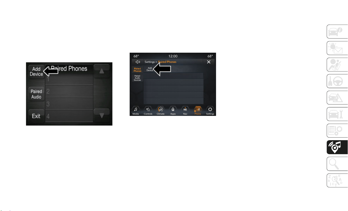
265
Mobile phone pairing is not available while
the vehicle is in motion.
A maximum of ten mobile phones can be
paired to the Uconnect system.
Start Pairing Procedure On The Radio
Uconnect 3:
Uconnect 3
1. P
lace the ignition in the ACC or ON posi-
tion.
2. Pr
ess the “Phone” button.
3. Select
“Settings.”
4. Select
“Paired Phones.”
5. Select
“Add device.”
Uconnect Phone will display an “In prog-
ress” screen while the system is
connectin
g.
Uconnect 4C & 4C NAV:
Uconnect 4C/4C NAV
1. Place the ignition in the ACC or ON posi-
tion.
2. Pr
ess the “Phone” button in the Menu
Bar on t
he touchscreen.
NOTE:
A message will pop-up stating, “Go to
‘Pairing’
to add or connect a phone.”
3. Press “Pairing.”
4. Press
“Paired Phones and Audio
Devices.
”
5. Select “Add device.”
NOTE:
Ucon
nect Phone will display an “In prog-
ress” screen while the system is connecting.
Phone pairing can also be accessed by:
1. P
ress the “Apps” button in the Menu Bar
on the t
ouchscreen.
2. Press “Settings”
3. Press
“Phone/Bluetooth”
4. Then,
proceed to follow the steps from
the abov
e procedure.
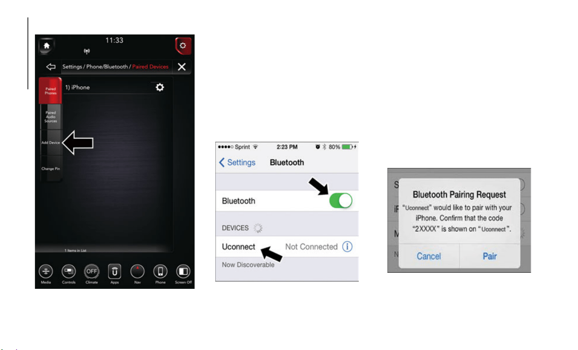
MULTIMEDIA
266
Uconnect 4C NAV With 12–inch Display:
Uconnect 4C NAV With 12–inch Display
1. Place the ignition in the ACC or ON posi-
tion.
2. Press the “Phone” button in the Menu
Bar on t
he touchscreen.
3. Select “Add device.”
Uconnect Phone will display an “In prog-
ress” screen while the system is
connectin
g.
Pair Your iPhone:
Bluetooth On/Uconnect Device
To search for available devices on your Blue-
tooth enabled iPhone:
1. Press the Settings button.
2. Select
Bluetooth.
Ensure the Bluetooth feature is enabled.
Once enabled, the mobile phone will
begin to search for Bluetooth connec
-
tions.
3. W
hen your mobile phone finds the Ucon-
nect sys
tem, select “Uconnect”.
Complete The iPhone Pairing Procedure:
Pairing Request

267
1. When prompted on the mobile phone,
accept the connection request from
Uconnect Phone.
NOTE:
Some mobile phones will require you to enter
the PIN n
umber.
Select The iPhone's Priority Level
When the pairing process has successfully
completed
, the system will prompt you to
choose whether or not this is your favorite
mobile phone. Selecting “Yes” will make this
mobile phone the highest priority. This
mobile phone will take precedence over
other paired mobile phones within range and
will connect to the Uconnect system auto
-
matically when entering the vehicle. Only
one mobil
e phone and/or one Bluetooth
audio device can be connected to the Ucon
-
nect system at a time. If “No” is selected,
simply se
lect “Uconnect” from the mobile
phone/audio device Bluetooth screen, and
the Uconnect system will reconnect to the
Bluetooth device.
Pair Your Android Device:
Uconnect Device
To search for available devices on your Blue-
tooth enabled Android Device:
1. P
ush the Menu button.
2. Select
Settings.
3. Select
Connections.
4. Turn B
luetooth setting to “On.”
Ensure the Bluetooth feature is enabled.
Once enabled, the mobile phone will
begin to search for Bluetooth connec
-
tions.
5. O
nce your mobile phone finds the Ucon-
nect sys
tem, select “Uconnect”.
You may be prompted by your mobile
phone to download the phonebook,
check “Do Not Ask Again” to automati
-
cally download the phonebook. This is so
you can m
ake calls by saying the name
of your contact.
Complete The Android Pairing Procedure:
Pairing Request
1. C
onfirm the passkey shown on the mobile
phone ma
tches the passkey shown on the
Uconnect system then accept the Blue
-
tooth pairing request.

MULTIMEDIA
268
NOTE:
Some mobile phones require the PIN to be
entered m
anually, enter the PIN number
shown on the Uconnect screen.
Select The Android Mobile Phone's Priority
Level
When
the pairing process has successfully
completed
, the system will prompt you to
choose whether or not this is your favorite
mobile phone. Selecting “Yes” will make this
mobile phone the highest priority. This
mobile phone will take precedence over
other paired mobile phones within range and
will connect to the Uconnect system auto
-
matically when entering the vehicle. Only
one mobil
e phone and/or one Bluetooth
audio device can be connected to the Ucon
-
nect system at a time. If “No” is selected,
simply se
lect “Uconnect” from the mobile
phone/audio device Bluetooth screen, and
the Uconnect system will reconnect to the
Bluetooth device.
NOTE:
Software updates, either on your phone or
U
connect
system, may interfere with the
Bluetooth connection.
If this happens,
simply re
peat the pairing process. However,
first, ma
ke sure to delete the device from the
list of phones on your Uconnect
system.
Next, be sure to remove Uconnect
from the
list of devices in your phone’s Blue-
tooth settings.
You are now ready to make hands-free calls.
P
ress the
Uconnect “Phone” button on
your steering wheel to begin.
NOTE:
Refer to UconnectPhone.com website for
additional information on mobile phone
p
airing a
nd for a list of compatible phones.
Common Phone Commands (Examples)
“Call John Smith”
“Call John Smith mobile”
“Dial 1 248 555 1212”
“Redial”
Mute (Or Unmute) Microphone During
Call
During a call, press the “Mute” button on
the Phone main screen to mute and
unmute the call.
Transfer Ongoing Call Between Handset
And Vehicle
During an on-going call, press the
“Transfer” button on the Phone main
screen to transfer an on-going call
between handset and vehicle.
Phonebook
The Uconnect system will automatically sync
your phonebook from your paired phone, if
this feature is supported by your phone.
Phonebook contacts are updated each time
that the phone is connected. If your phone
book entries do not appear, check the
settings on your phone. Some phones require
you to enable this feature manually.
Your phonebook can be browsed on the
Uconnect system touchscreen, but editing
can only be done on your phone. To
browse, press the “Phone” button on the
touchscreen, then the “Phonebook”
button on the touchscreen.
Favorite phonebook entries can be saved as
Favorites
for quicker access. Favorites are
shown at the top of the main phone screen.

269
Voice Command Tips
Speaking complete names (i.e; Call John
Doe vs. Call John) will result in greater
system accuracy.
You can “link” commands together for
faster results. Say “Call John Doe,
mobile,” for example.
If you are listening to available voice
command options, you do not have to
listen to the entire list. When you hear the
command that you need, push the
button on the steering wheel, wait for the
beep and say your command.
Changing The Volume
Start a dialogue by pushing the VR button
, then say a command. For example,
"Help".
Use the radio VOLUME/MUTE rotary knob
to adjust the volume to a comfortable level
while the Uconnect system is speaking.
NOTE:
The volume setting for Uconnect is different
than the
audio system.
NOTE:
To access help, push the Uconnect VR
b
utton (i
f active) on the steering wheel
and say "help." Push the Uconnect VR
P
ickup bu
tton (if active) or the VR button
(if active) and say "cancel" to cancel the
help session.
Using Do Not Disturb
With Do Not Disturb, you can disable notifi-
cations from incoming calls and texts,
allowing
you to keep your eyes on the road
and hands on the wheel. For your conve
-
nience, there is a counter display to keep
track of
your missed calls and text messages
while you were using Do Not Disturb.
Do Not Disturb can automatically reply with
a text me
ssage, a call or both, when
declining an incoming call and send it to
voicemail.
Automatic reply messages can be:
“I am driving right now, I will get back to
you shortly.”
Create a custom auto reply message up to
160 characters.
While in Do Not Disturb, Conference Call can
be select
ed so you can still place a second
call without being interrupted by incoming
calls.
NOTE:
Only the beginning of your custom
message will be seen on the touchscreen.
Reply with text message is not compatible
with iPhones.
Auto reply with text message is only avail-
able on phones that supporting Bluetooth
MAP.
Incoming Text Messages
After pairing your Uconnect system with a
Bluetooth enabled mobile device with the
Message Access Profile (MAP), the Uconnect
system can announce a new incoming text
message and read it to you over the vehicle’s
audio system.
NOTE:
Only incoming text messages received during
the curre
nt ignition cycle can be viewed/
read.
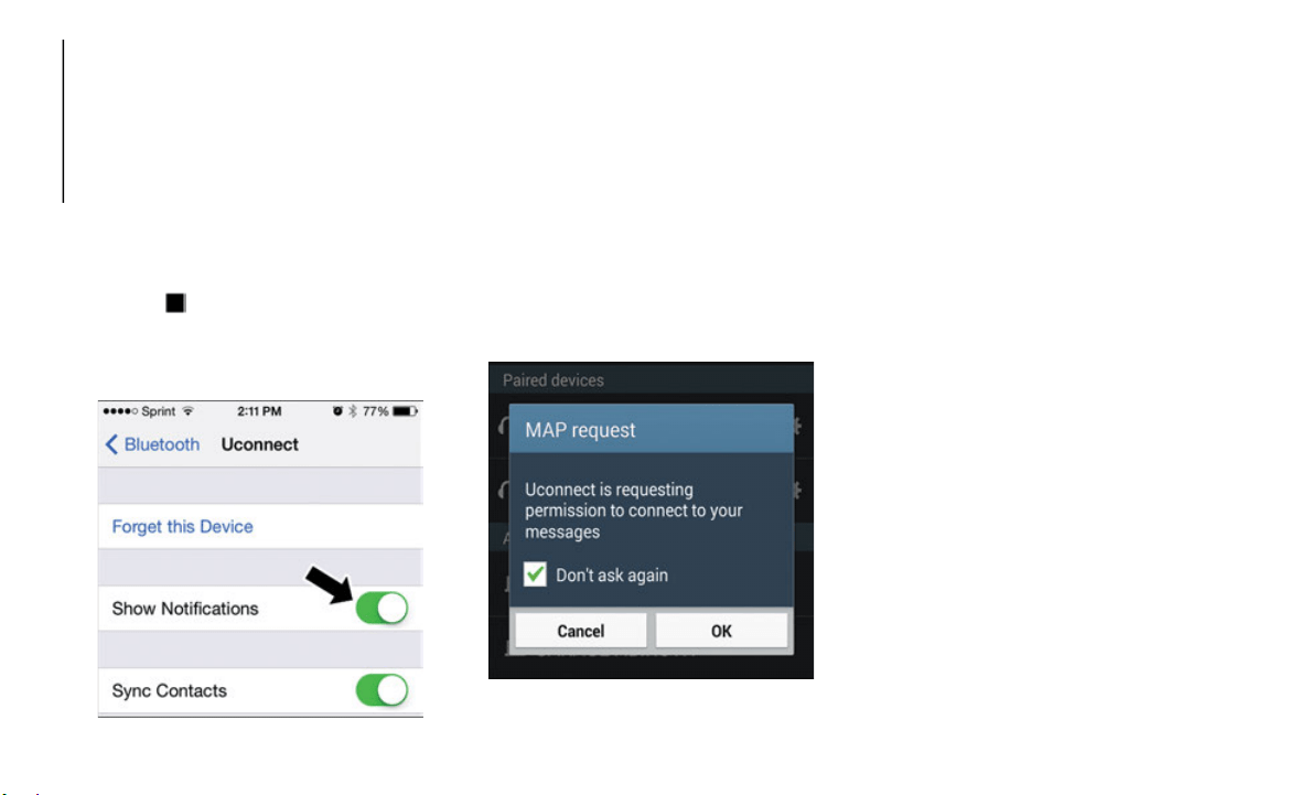
MULTIMEDIA
270
To enable incoming text messaging:
iPhone
1. Press the settings button on the mobile
phone.
2. S
elect Bluetooth.
Ensure Bluetooth is enabled, and the
mobile phone is paired to the Uconnect
system.
3. Select located
under DEVICES next to
Uconnect.
4. T
urn “Show Notifications” to on.
Enable i
Phone Incoming Text Messages
Android Devices
1. Push the Menu button on the mobile
phone.
2. Select Settings.
3. Select
Connections.
4. Turn “
Show Notifications” to on.
A pop up will appear asking you to
accept a request for permission to
connect to your messages. Select “Don’t
ask again” and press OK.
Enable Android Device Incoming Text
Messages
NOTE:
All incoming text messages received during
the curre
nt ignition cycle will be deleted
from the Uconnect system when the ignition
is turned to the OFF position.
Helpful Tips And Common Questions To
Improve Bluetooth Performance With
Your Uconnect System
Mobile Phone won’t reconnect to system after
pairing:
Set mobile phone to auto-connect or
trusted device in mobile phone Bluetooth
settings (Blackberry devices).
Perform a factory reset on your mobile
phone. Refer to your mobile phone manu-
facturer or cellular provider for instruc-
tions.
Many mobile phones do not automatically
reconnect after being restarted (hard
reboot). Your mobile phone can still be
connected manually. Close all applica
-
tions that may be operating (refer to
mobile ph
one manufacturer’s instruc-
tions), and follow “Pairing (Wirelessly
C
onnectin
g) Your Mobile Phone To The
Uconnect System”.

271
Mobile Phone won’t pair to system:
Perform a hard reset in the mobile phone by
removing the battery (if removable — see
your mobile phone’s owner manual).
Delete pairing history in mobile phone and
Uconnect system; usually found in phone’s
Bluetooth connection settings.
Verify you are selecting “Uconnect” in the
discovered Bluetooth devices on your mobile
phone.
If your vehicle system generates a pin code
the default is 0000.
Mobile Phonebook didn’t download:
Check “Do not ask again,” then accept the
“phonebook download” request on your
mobile phone.
Up to 5,000 contact names with four
numbers per contact will transfer to the
Uconnect 4C/4C NAV system phonebook.
Can’t make a conference call:
CDMA (Code-Division Multiple Access)
carriers do not support conference calling.
Refer to your mobile phone user’s manual for
further information.
Making calls while connected to AUX:
Plugging in your mobile phone to AUX while
connected to Bluetooth will disable
Hands-Free Calling. Do not make calls while
your mobile phone is plugged into the AUX
jack.
VOICE RECOGNITION
QUICK TIPS
Introducing Uconnect
Start using Uconnect Voice Recognition with
these helpful quick tips. It provides the key
Voice Commands and tips you need to know
to control your Uconnect system.
If you see the NAV icon on the bottom bar, or
in the Ap
ps menus, of your touchscreen, you
have the Uconnect 4C NAV With 8.4–inch
Display or the Uconnect 4C NAV With
12–inch Display system. If not, you have a
Uconnect 4C With 8.4–inch Display system.
Get Started
All you need to control your Uconnect system
with your voice are the buttons on your steering
wheel.
1. Visit UconnectPhone.com to che
ck mobile
device and feature compatibility and to find
phone pai
ring instructions.
2. Reduce background noise. Wind noise and
passenge
r conversations are examples of
noise that may impact recognition.
3. Speak clearly at a normal pace and volume
while fa
cing straight ahead. The micro-
phone is located in the headliner and
a
imed at
the driver.
4. Each time you give a Voice Command, you
must fir
st push either the VR or Phone
button, wait until after the beep, then say
your Voice Command.
5. You can interrupt the help message or
system p
rompts by pushing the VR or
Phone button and saying a Voice Command
from current category.
Uconnect Voice Command Buttons
1 — Push To Initiate Or To Answer A Phone Call,
S
end Or R
eceive A Text
2 — For All Radios: Push To Begin Radio Or Me-
dia Functions. For 4C/4C NAV Only: Push To Be-
gin Navigation, Apps And Climate Functions
3 — Push To End Call
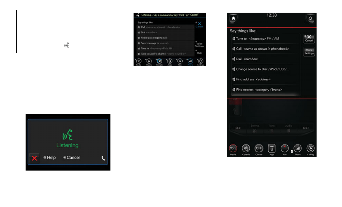
MULTIMEDIA
272
Basic Voice Commands
The basic Voice Commands below can be
given at any point while using your Uconnect
system.
Push the VR button . After the beep, say:
“Cancel” to stop a current voice session
“Help” to hear a list of suggested Voice
Commands
“Repeat” to listen to the system prompts
again
Notice the visual cues that inform you of your
voice rec
ognition system’s status. Cues
appear on the top of the touchscreen.
Uconnect 3 With 5–inch Display Radio Visual
Cues
Uconnect 4C/4C NAV With 8.4–inch Display
Radio Visual Cues
Uconnect 4C NAV With 12–inch Display Radio
Visual Cues
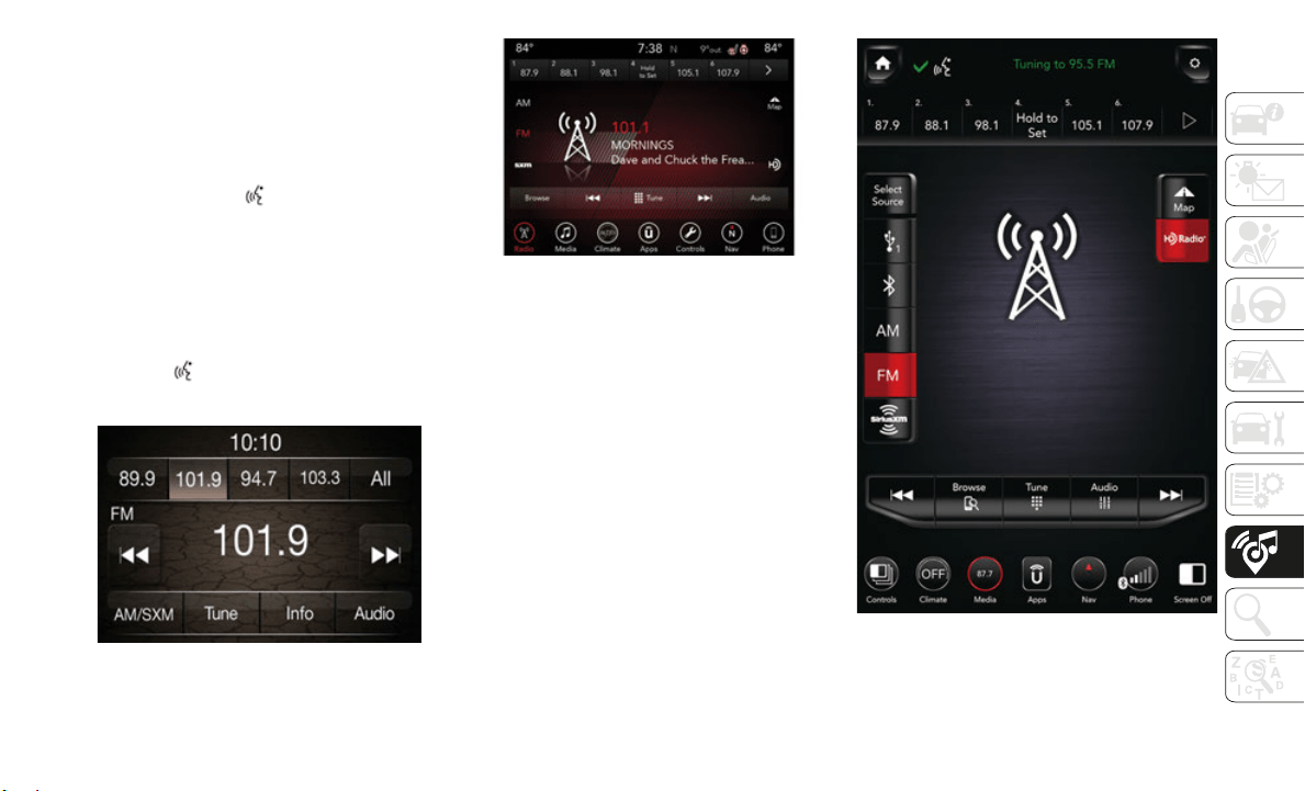
273
Radio
Use your voice to quickly get to the AM, FM
or SiriusXM Satellite Radio stations you
would like to hear. (Subscription or included
SiriusXM Satellite Radio trial required.)
Push the VR button . After the beep, say:
“Tune to ninety-five-point-five FM”
“Tune to Satellite Channel Hits 1”
TIP:
At any time, if you are not sure of what to say
or want t
o learn a Voice Command, push the
VR button and say “Help.” The
system
provides you with a list of commands.
Uconnect 3 Radio
Uconnect 4C/4C NAV With 8.4–inch Display
Radio
Uconnect 4C NAV With 12–inch Display Radio

MULTIMEDIA
274
Media
Uconnect offers connections via USB, Blue-
tooth and auxiliary ports (If Equipped). Voice
operation
is only available for connected
USB and AUX devices. (Remote CD player
optional and not available on all vehicles.)
Push the VR button . After the beep, say
one of the following commands and follow
the promp
ts to switch your media source or
choose an artist.
“Change source to Bluetooth”
“Change source to AUX”
“Change source to USB”
“Play artist Beethoven”; “Play album
Greatest Hits”; “Play song Moonlight
Sonata”; “Play genre Classical”
TIP:
Press the Browse button on the touchscreen
to see al
l of the music on your USB device.
Your Voice Command must match exactly
how the artist, album, song and genre infor
-
mation is displayed.
Uconnect 3 Media
Uconnect 4C/4C NAV With 8.4–inch Display
Media
Uconnect 4C NAV With 12–inch Display Media
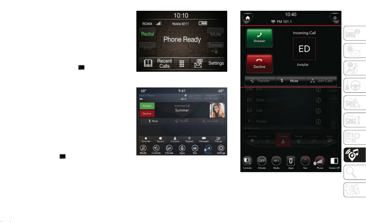
275
Phone
Making and answering hands-free phone
calls is easy with Uconnect. When the
Phonebook button is illuminated on your
touchscreen, your system is ready. Check
UconnectPhone.com for mobile phone
compatibility and pairing instructions.
Push the Phone button . After the beep,
say one of the following commands:
“Call John Smith”
“Dial 123-456-7890 and follow the
system prompts”
“Redial (call previous outgoing phone
number)”
“Call back (call previous incoming phone
number)”
TIP:
When providing a Voice Command, push the
P
hone but
ton and say “Call,” the
n
pronounce the name exactly as
it appears in
your phone book. When a contact has
multiple phone numbers, you can say “Call
John Smith work.”
Uconnect 3 Phone
Uconnect 4C/4C NAV With 8.4–inch Display
Phone
Uconnect 4C NAV With 12–inch Display Phone
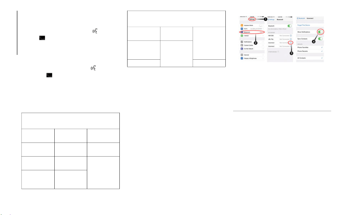
MULTIMEDIA
276
Voice Text Reply — If Equipped
Uconnect announces incoming text
messages. Push the VR button or Phone
button (if enabled) and say “Listen.”
(Mus
t have compatible mobile phone paired
to Uconnec
t system.)
1. Once an incoming text message is read to
you, push
the VR button or Phone
button (if enabled). After the beep,
say: “R
eply.”
2. Listen
to the Uconnect prompts. After
the beep,
repeat one of the pre-defined
messages and follow the system prompts.
NOTE:
Only use the numbering listed, otherwise the
system doe
s not transpose the message.
TIP:
Your mobile phone must have the full imple-
mentation of the Message Ac
cess Profile
(MAP) to take advantage of this feature. For
details about MAP, visit
Uconnect-
Phone.com.
Apple iPhone iOS 6 or later supports reading
incoming te
xt messages only. To enable this
feature on your Apple iPhone, follow these
four simple steps:
iPhone Notification Settings
TIP:
Voice Text Reply is not compatible with
i
Phone, bu
t if your vehicle is equipped with
Siri Eyes Free, you can use your voice to send
a text message.
Climate (4C/4C NAV)
Too hot? Too cold? Adjust vehicle tempera-
tures hands-free and keep everyone comfort-
able while you keep moving ahead. (If
v
ehicle is
equipped with climate control.)
PRE-DEFINED VOICE TEXT REPLY
RESPONSES
Yes. Stuck in
traffic.
See you
later.
No. Start without
me.
I’ll be
late.
Okay. Where are
you?
I will
be 5
<or 10, 15,
20, 25, 30,
45, 60>
minutes late.
Call me. Are you
there yet?
I’ll call you
later.
I need
directions.
See you in 5
<or 10, 15,
20, 25, 30,
45, 60>
minutes.
I’m on my
way.
Can’t t
alk
right now.
I’m lost. Thanks.
PRE-DEFINED VOICE TEXT REPLY
RESPONSES
1 — Select “Settings”
2 — Select “Bluetooth”
3 — Select The (i) For The Paired Vehicle
4 — Turn On “Show Notifications”
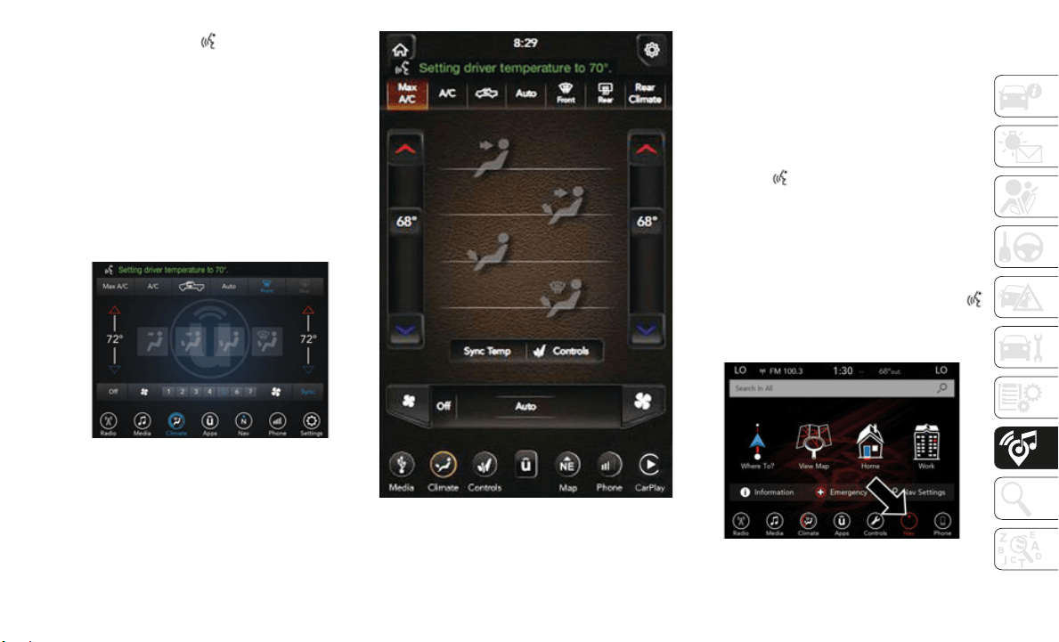
277
Push the VR button . After the beep, say
one of the following commands:
“Set driver temperature to 70 degrees”
“Set passenger temperature to 70 degrees”
TIP:
Voice Command for Climate may only be
used to a
djust the interior temperature of
your vehicle. Voice Command will not work to
adjust the heated seats or steering wheel if
equipped.
Uconnect 4C/4C NAV With 8.4–inch Display
Climate
Uconnect 4C NAV With 12–inch Display
Climate
Navigation (4C NAV)
The Uconnect navigation feature helps you
save time and become more productive when
you know exactly how to get to where you
want to go.
1. To enter a destination, push the VR
button .
After the beep, say: “Find
addres
s 800 Chrysler Drive Auburn Hills,
Michigan
.”
2. Then follow the system prompts.
TIP:
To st
art a POI search, push the VR button .
After the beep, say: “F
ind near
est coffee
shop.”
Uconnect 4C NAV With 8.4–inch Display
Navigation
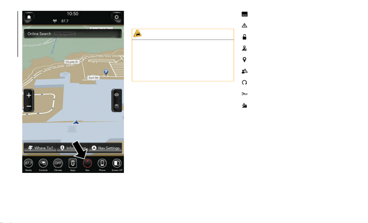
MULTIMEDIA
278
Uconnect 4C NAV With 12–inch Display
Navigation
SiriusXM Guardian (4C/4C NAV) — If
Equipped
NOTE:
Your vehicle may be transmitting data as
authorize
d by the subscriber.
An included trial and/or subscription is
required
to take advantage of the SiriusXM
Guardian services in the next section of this
guide. To register with SiriusXM Guardian,
press the Apps button on your 8.4-inch or
12–inch touchscreen to get started.
NOTE:
SiriusXM Guardian is available only on
equipped
vehicles purchased within the
continental United States, Alaska, Hawaii,
and Canada. Services can only be used
where coverage is available; see coverage
map for details.
SOS Call
Theft Alarm Notification
Remote Door Lock/Unlock
Send & Go
Vehicle Finder-If Equipped
Stolen Vehicle Assistance
Remote Vehicle Start**
Remote Horn & Lights
Roadside Assistance Call
Vehicle Health Reports-If Equipped**
Vehicle Health Alert**
Performance Pages Plus**
**If vehicle is equipped.
CAUTION!
Some SiriusXM Guardian services,
including SOS Call and Roadside
Assistance Call will NOT work without an
operable LTE (voice/data) or 3G or 4G
(data) network connection compatible with
your device.
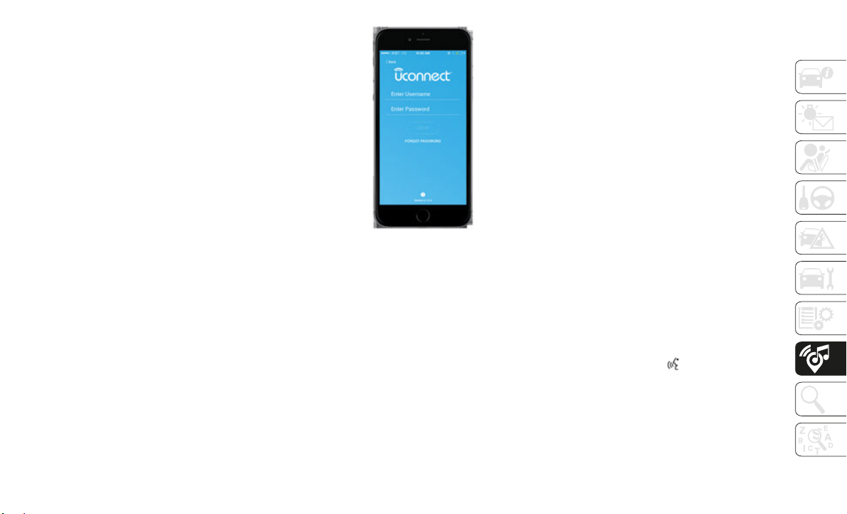
279
Register (4C/4C NAV)
To unlock the full potential of SiriusXM
Guardian in your vehicle, you must activate
your SiriusXM Guardian services.
1. Press the Apps icon on the bottom of your
in-vehic
le touchscreen.
2. Select the Activate Services icon from
your lis
t of apps.
3. Select “Customer Care” to speak with a
SiriusXM
Guardian Customer Care agent
who will activate services in your vehicle,
or select “Enter Email” to activate on the
web.
For further information:
U.S. residents visit: siriusxm.com/
guardian
Canadian residents visit: siriusxm.ca/
guardian
Mobile App (4C/4C NAV)
You’re only a few steps away from using
remote commands and playing your favorite
music in your car.
Mobile App
To use the Uconnect App:
Download the Uconnect App to your
mobile device.
Press the Info button on the navigation bar
at the bottom of the app for Vehicle Info.
Press the Remote button on the navigation
bar at the bottom of the app to Lock/
Unlock, Remote Start, and activate your
horn and lights remotely.
Press the Location button on the naviga-
tion bar at the bottom of the app to bring
up a map
to locate your vehicle or send a
location to your vehicle’s navigation
system.
Press the Settings button in the upper left
corner of the app to bring up app settings
and access the Assist Call Centers.
NOTE:
For further information please visit DriveUco-
nnect.com (U.S. Residents) or DriveUcon-
nect.ca (Canadian Residents).
SiriusXM Travel Link (4C NAV)
Need to find a gas station, view local movie
listings, check a sports score or the 5 - day
weather forecast? SiriusXM Travel Link is a
suite of services that brings a wealth of infor
-
mation right to your Uconnect 4C NAV
system.
Pus
h the VR button . After the beep, say
one of the following commands:
“Show fuel prices”
“Show 5 - day weather forecast”
“Show extended weather”
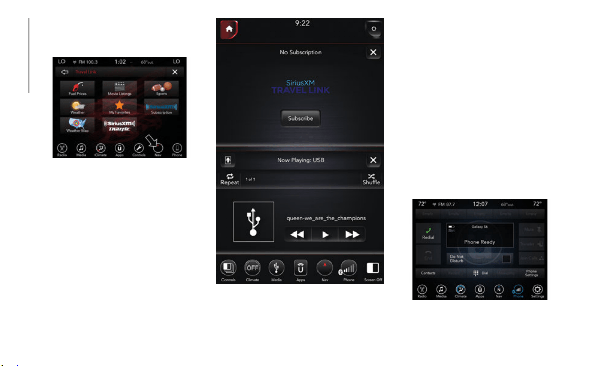
MULTIMEDIA
280
TIP:
Traffic alerts are not accessible with Voice
Command.
Uc
onnect 4C NAV With 8.4–inch Display
SiriusXM Travel Link
Uconnect 4C NAV With 12–inch Display
SiriusXM Travel Link
Siri Eyes Free — If Equipped
Siri lets you use your voice to send text
messages, select media, place phone calls
and much more. Siri uses your natural
language to understand what you mean and
responds back to confirm your requests. The
system is designed to keep your eyes on the
road and your hands on the wheel by letting
Siri help you perform useful tasks.
To enable Siri, push and hold, then release
the Uconn
ect Voice Recognition (VR) button
on the steering wheel. After you hear a
double beep you can ask Siri to play
podcasts and music, get directions, read text
messages and many other useful requests.
Uconnect 4C/4C NAV With 8.4–inch Siri Eyes
Free Available
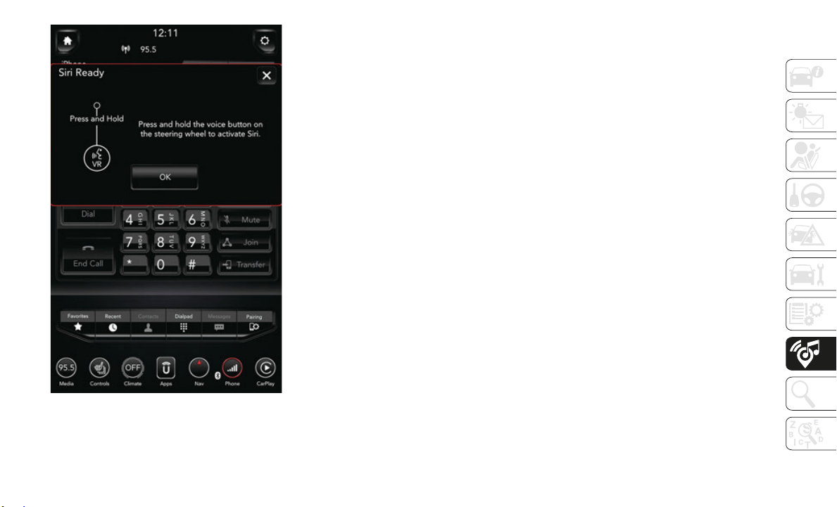
281
Uconnect 4C NAV With 12–inch Siri Eyes Free
Available
Using Do Not Disturb
With Do Not Disturb, you can disable notifi-
cations from incoming calls and texts,
allowing
you to keep your eyes on the road
and hands on the wheel. For your conve
-
nience, there is a counter display to keep
track of
your missed calls and text messages
while you were using Do Not Disturb.
Do Not Disturb can automatically reply with
a text me
ssage, a call, or both, when
declining an incoming call and send it to
voicemail.
Automatic reply messages can be:
“I am driving right now, I will get back to
you shortly.”
Create a custom auto reply message up to
160 characters.
While in Do Not Disturb, Conference Call can
be select
ed so you can still place a second
call without being interrupted by incoming
calls.
NOTE:
Only the beginning of your custom
message will be seen on the touchscreen.
Reply with text message is not compatible
with iPhones.
Auto reply with text message is only avail-
able on phones that support Bluetooth
MAP.
Android Auto — If Equipped
NOTE:
Feature availability depends on your carrier
and mobil
e phone manufacturer. Some
Android A
uto features may or may not be
available in every region and/or language.
Android Auto allows you to use your voice to
interact
with Android’s best-in-class speech
technology through your vehicle’s voice
recognition system, and use your smart
-
phone’s data plan to project your Android
powered s
martphone and a number of its
apps onto your Uconnect touchscreen.
Connect your Android 5.0 (Lollipop), or
higher, to one of the media USB ports, using
the factory-provided USB cable, and press
the new Android Auto icon that replaces your
“Phone” icon on the main menu bar to begin
Android Auto. Push and hold the VR button
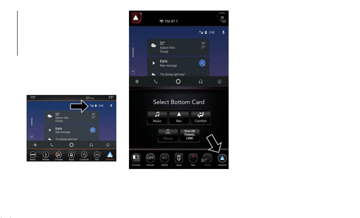
MULTIMEDIA
282
on the steering wheel, or press and hold the
“Microphone” icon within Android Auto, to
activate Android’s VR, which recognizes
natural voice commands, to use a list of your
smartphone’s features:
Maps
Music
Phone
Text Messages
Additional Apps
Uconnect 4/4C/4C NAV With 8.4–inch Display
Android Auto
Uconnect 4C NAV With 12–inch Display
Android Auto
Refer to your Uconnect Owner’s Manual
Supplemen
t for further information.
NOTE:
Requires compatible smartphone running
A
ndroid 5
.0 Lollipop or higher and download
app on Google Play. Android, Android Auto,
and Google Play are trademarks of Google
Inc.
Apple CarPlay — If Equipped
NOTE:
Feature availability depends on your carrier
and mobil
e phone manufacturer. Some
Apple Car
Play features may or may not be
available in every region and/or language.
Apple CarPlay allows you to use your voice to
interact
with Siri through your vehicle’s voice
recognition system, and use your smart
-
phone’s data plan to project your iPhone and
a number
of its apps onto your Uconnect
touchscreen. Connect your iPhone 5, or
higher, to one of the media USB ports, using
the factory-provided Lightning cable, and
press the new CarPlay icon that replaces your
“Phone” icon on the main menu bar to begin
Apple CarPlay. Press and hold the VR button
on the steering wheel, or press and hold the

283
“Home” button within Apple CarPlay, to acti-
vate Siri, which recognizes natural voice
commands
to use a list of your iPhone’s
features:
Phone
Music
Messages
Maps
Additional Apps
Uconnect 4/4C/4C NAV With 8.4–inch Display
Apple CarPlay
Uconnect 4C NAV With 12–inch Display Apple
CarPlay
Refer to your Uconnect Owner’s Manual
Supplemen
t for further information.
NOTE:
Requires compatible iPhone. See dealer for
p
hone com
patibility. Data plan rates apply.
Vehicle u
ser interface is a product of Apple.
Apple CarPlay is a trademark of Apple Inc.
i
Phone is
a trademark of Apple Inc., regis-
tered in the US and other countries. Apple
t
erms of
use and privacy statements apply.
General Information
The following regulatory statement applies to
all Radio Frequency (RF) devices equipped
in this vehicle:
This device complies with Part 15 of the FCC
Rules and
with Industry Canada
license-exempt RSS standard(s). Operation
is subject to the following two conditions:
1. This device may not cause harmful inter-
ference,
and
2. This device must accept any interference
received
, including interference that may
cause undesired operation.
NOTE:
Changes or modifications not expressly
approved
by the party responsible for compli-
ance could void the user’s authority to
o
perate t
he equipment.

MULTIMEDIA
284
Additional Information
© 2018 FCA US LLC. All rights reserved.
Mopar and Uconnect are registered trade-
marks and Mopar Owner Connect is a trade-
mark of FCA US LLC. Android is a trademark
o
f Google
Inc. SiriusXM and all related marks
and logos are trademarks of SiriusXM Radio
Inc.
Uconnect System Support:
U.S. residents visit www.DriveUcon-
nect.com or call: 1-877-855
-8400 (24
hours a day 7 days a week)
Canadian residents visit www.DriveUcon-
nect.ca or call: 1-800-465
-2001
(English) or 1-800-387
-9983(French)
SiriusXM Guardian services support:
U.S. residents visit www.siriusxm.com/
guardian or call: 1-844-796-4827
Canadian residents visit www.siriusxm.ca/
guardian or call: 1-877-324-9091

285
IF YOU NEED ASSISTANCE
The manufacturer and its authorized dealer
are vitally interested in your satisfaction. We
want you to be happy with our products and
services.
Warranty service must be done by an autho-
rized dealer. We strongly recommend that
you take t
he vehicle to an authorized dealer.
They know your vehicle the best, and are
most concerned that you get prompt and
high quality service. The manufacturer's
authorized dealer have the facilities,
factory-trained technicians, special tools,
and the latest information to ensure the
vehicle is fixed correctly and in a timely
manner.
This is why you should always talk to an
authorized
dealer service manager first. Most
matters can be resolved with this process.
If for some reason you are still not satis-
fied, talk to the general manager or owner
of the aut
horized dealer. They want to
know if you need assistance.
If an authorized dealer is unable to resolve
the concern, you may contact the manu-
facturer's customer center.
Any communication to the manufacturer's
customer c
enter should include the following
information:
Owner's name and address
Owner's telephone number (home and
office)
Authorized dealer name
Vehicle Identification Number (VIN)
Vehicle delivery date and mileage
FCA US LLC Customer Center
P.O. Box 21–8004
Auburn Hills, MI 48321–8004
Phone: (866) 726-4636
FCA Canada Inc. Customer Center
P.O. Box 1621
Windsor, Ontario N9A 4H6
Phone: (800) 465-2001 English / (800)
3
87-9983 F
rench
In Mexico Contact
Av. Prolongacion Paseo de la Reforma, 1240
Sante Fe C.P. 05109
Mexico, D. F.
In Mexico City: 800-505-1300
Outside Mexico City: +(52)55 50817568
Puerto Rico And U.S. Virgin Islands
FCA Caribbean LLC
P.O. Box 191857
San Juan 00919-1857
Phone: (866) 726-4636
Fax: (787) 782-3345
Customer Assistance For The Hearing Or
Speech Impaired (TDD/TTY)
To assist customers who have hearing diffi-
culties, the manufacturer has installed
special TD
D (Telecommunication Devices for
the Deaf) equipment at its customer center.
Any hearing or speech impaired customer,
who has access to a TDD or a conventional
teletypewriter (TTY) in the United States,
can communicate with the manufacturer by
dialing 1-800-380-CHRY.
Canadian residents with hearing difficulties
that require assistance can use the special
needs relay service offered by Bell Canada.
For TTY teletypewriter users, dial 711 and
for Voice callers, dial 1-800-855-0511 to
connect with a Bell Relay Service operator.

CUSTOMER ASSISTANCE
286
Service Contract
You may have purchased a service contract for
a vehicle to help protect you from the high cost
of unexpected repairs after the manufacturer's
New Vehicle Limited Warranty expires. The
manufacturer stands behind only the manufac
-
turer's service contracts. If you purchased a
manufactur
er's service contract, you will
receive Plan Provisions and an Owner Identifi
-
cation Card in the mail within three weeks of
the vehicl
e delivery date. If you have any ques-
tions about the service contract, call the manu-
facturer's Service Contract National Customer
H
otline at
1-800-521-9922 (Canadian resi-
dents, call (800) 465-2001 English / (800)
3
87-9983 F
rench).
The manufacturer will not stand behind any
service co
ntract that is not the manufacturer's
service contract. It is not responsible for any
service contract other than the manufacturer's
service contract. If you purchased a service
contract that is not a manufacturer's service
contract, and you require service after the
manufacturer's New Vehicle Limited Warranty
expires, please refer to the contract docu
-
ments, and contact the person listed in those
documents.
W
e appreciate that you have made a major
investment
when you purchased the vehicle.
An authorized dealer has also made a major
investment in facilities, tools, and training to
assure that you are absolutely delighted with
the ownership experience. You will be pleased
with their sincere efforts to resolve any warranty
issues or related concerns.
REPORTING SAFETY
DEFECTS
In The 50 United States And
Washington, D.C.
If you believe that your vehicle has a defect
that could cause a crash or cause injury or
death, you should immediately inform the
National Highway Traffic Safety Administra
-
tion (NHTSA) in addition to notifying FCA US
LLC.
If NHTSA receives similar complaints,
it may open an investigation, and if it
finds that a safety defect exists in a
group of vehicles, it may order a recall
and remedy campaign. However,
NHTSA cannot become involved in
individual problems between you, an
authorized dealer or FCA US LLC.
To contact NHTSA, you may call the
Vehicle Sa
fety Hotline toll free at
1-888-327-4236 (TTY:
1-800-424-9153); or go to http://
www.safercar.gov; or write to: Admin-
istrator, NHTSA, 1200 New Jersey
Avenue, SE
., West Building, Wash-
ington, D.C. 20590. You can also
obtain oth
er information about motor
vehicle safety from http://
www.safercar.gov.
WARNING!
Engine exhaust (internal combustion engines
only), some of its constituents, and certain
vehicle components contain, or emit,
chemicals known to the State of California to
cause cancer and birth defects, or other
reproductive harm. In addition, certain fluids
contained in vehicles and certain products of
component wear contain, or emit, chemicals
known to the State of California to cause
cancer and birth defects, or other
reproductive harm.

287
In Canada
If you believe that your vehicle has a
safety defect, you should contact the
Customer Service Department imme-
diately. Canadian customers who wish
to report
a safety defect to the Cana-
dian government should contact
Transport
Canada, Motor Vehicle
Defect Investigations and Recalls at
1-800-333-0510 or go to http://
www.tc.gc.ca/roadsafety/.
PUBLICATION ORDER
FORMS
You can purchase a copy of the Owner's
Manual, United States customers may
visit the Ram Truck Contact Us page at
www.ramtrucks.com scroll to the bottom
of the page and select the “Contact Us”
link, the
n select the “Owner’s Manual and
Glove Compartment Material” from the
left menu. You can also purchase a copy
by calling 1-866-726-4636 (U.S.) or
1-800-387-1143 (Canada).
Replacement User Guide kits or, if you
prefer, additional printed copies of the
Owner's Manual, may be purchased by
visiting
www.techauthority.com (U.S.) or
by calling 1-800-890-4038 (U.S.) or
1-800-387
-1143 (Canada).
NOTE:
The Owner's Manual and User Guide elec-
tronic files are also available on the
Chrysler,
Jeep, Ram Truck, Dodge and
SRT websites.
Click on the “Owners” tab, select “Owner
And Service Manuals”. Then select your
desired model year and vehicle from the
drop down lists.

288
Index
Index
A
Accessories
.................................................232
Mopar
......................................................232
Adaptive Cruise Control (ACC) (Cruise
Control)
Off
....................................................151, 153
On
....................................................151, 153
Adding Fuel
.................................................165
Additives, Fuel
............................................166
Adjustable Pedals
........................................26
Air Bag
Air Bag Operation
..................................100
Air Bag Warning Light
.....................97, 100
Enhanced Accident Response
......109, 203
Event Data Recorder (EDR)
..................203
Front Air Bag
..........................................100
If Deployment Occurs
............................108
Knee Impact Bolsters
............................105
Maintaining Your Air Bag System
........109
Maintenance
...........................................109
Redundant Air Bag Warning Light
.........98
Transporting Pets
...................................125
Air Bag Light
...................................68, 97, 126
Air Conditioning
...........................................42
Air Conditioning Filter
.................................43
Air Conditioning System
..............................42
Air Conditioning, Operating Tips
................43
Air Pressure
Tires
......................................................... 219
Air Suspension
................................... 140, 143
Alarm
Panic
......................................................... 12
Security Alarm
................................... 15, 69
Android Auto
...................................... 241, 281
Apps
........................................................ 245
Communication
...................................... 244
Maps
........................................................ 242
Music
....................................................... 243
Antifreeze (Engine Coolant)
..................... 228
Anti-Lock Warning Light
............................. 74
Apple CarPlay
..................................... 245, 282
Apps
........................................................ 248
Maps
........................................................ 247
Messages
................................................ 247
Music
....................................................... 247
Phone
...................................................... 246
Audio Systems (Radio)
.............................. 235
Auto Down Power Windows
........................ 44
Auto Unlock, Doors
.................................... 136
Automatic Headlights
.................................. 30
Automatic High Beams
............................... 29
Automatic Tailgate Release
........................ 50
Automatic Temperature Control (ATC)
...... 42
Automatic Transmission
........................... 135
Fluid Type
............................................... 231
Automatic Transmission Limp Home
Mode
........................................................... 136
AUX Cord
.................................................... 257
Auxiliary Driving Systems
........................... 80
Axle Fluid
................................................... 231
B
Back-Up
...................................................... 161
Back-Up Camera
....................................... 161
Battery
.......................................................... 69
Charging System Light
........................... 69
Battery Saver Feature
................................. 32
Belts, Seat
.................................................. 126
Blind Spot Monitoring
................................ 80
Body Builders Guide
................................... 10
B-Pillar Location
........................................ 216
Brake Fluid
................................................. 231
Brake System
Parking
................................................... 131
Warning Light
.......................................... 68
Brake/Transmission Interlock
.................. 135
Bulb Replacement
.................................... 179
Bulbs, Light
........................................ 127, 179
C
Camera
........................................................ 161
Camera, Rear
..................................... 161, 163
Camper
.......................................................... 63

289
Capacities, Fuel..........................................228
Caps, Filler
Oil (Engine)
.............................................209
Carbon Monoxide Warning
........................125
Cargo Light
....................................................32
Chart, Tire Sizing
.......................................213
Checking Your Vehicle For Safety
............125
Checks, Safety
............................................125
Child Restraint
...........................................110
Child Restraints
Booster Seats
.........................................113
Child Seat Installation
..................120, 121
How To Stow An unused ALR Seat
Belt
......................................................119
Infant And Child Restraints
..................112
Locating The LATCH Anchorages
........117
Lower Anchors And Tethers For
Children
..............................................114
Older Children And Child Restraints
...112
Seating Positions
...................................114
Cleaning
Wheels
.....................................................225
Climate Control
.............................................34
Automatic
..................................................35
Clock Settings
.............................................235
Compact Spare Tire
...................................224
Contract, Service
........................................286
Cooling System
Cooling Capacity
....................................228
Selection Of Coolant
(Antifreeze)
.................................228, 229
Cruise Light
.................................................. 77
Customer Assistance
................................. 285
Cybersecurity
.............................................. 233
D
Daytime Running Lights
............................. 29
Defroster, Windshield
................................ 126
Delay (Intermittent) Wipers
........................ 33
Diagnostic System, Onboard
...................... 78
Differential, Limited Slip
.......................... 146
Disabled Vehicle Towing
........................... 200
Do Not Disturb
................................... 269, 281
Door Ajar
................................................. 70, 71
Door Ajar Light
....................................... 70, 71
Doors
............................................................. 16
Driver’s Seat Back Tilt
................................ 19
Dual Rear Wheels
...................................... 228
E
Electric Parking Brake
.............................. 131
Electrical Power Outlets
............................. 55
Electronic Range Select (ERS)
................ 137
Electronic Speed Control (Cruise
Control)
....................................................... 149
Electronic Throttle Control Warning
Light
.............................................................. 70
Electronically Shifted Transfer
Case
..................................................... 137, 139
Emergency, In Case Of
Freeing Vehicle When Stuck
................ 199
Hazard Warning Flasher
....................... 175
Jump Starting
........................................ 196
Engine
......................................................... 209
Block Heater
.......................................... 130
Break-In Recommendations
................ 131
Compartment
......................... 209, 210, 211
Compartment
Identification
..................... 209, 210, 211
Coolant (Antifreeze)
.............................. 229
Exhaust Gas Caution
............................. 125
Fuel Requirements
................................ 228
Jump Starting
........................................ 196
Oil
.................................................... 228, 229
Oil Filler Cap
.......................................... 209
Oil Selection
.......................................... 228
Overheating
............................................ 198
Starting
................................................... 128
Enhanced Accident Response
Feature
................................................ 109, 203
Exhaust Gas Cautions
............................... 125
Exhaust System
......................................... 125
Exterior Lighting
.......................................... 28
Exterior Lights
...................................... 28, 127
F
Filters
Air Conditioning
...................................... 43
Engine Oil
.............................................. 229
Flashers
Turn Signals
............................... 31, 77, 127
Flash-To-Pass
............................................... 30

290
Index
Flat Tire .......................................................221
Changing
.................................................187
Stowage
...................................................194
Fluid Capacities
.........................................228
Fluid Leaks
.................................................127
Fluid, Brake
................................................231
Fluids And Lubricants
...............................229
Fog Lights
.....................................................31
Fold-Flat Seats
.............................................19
Forward Collision Warning
..........................82
Four Wheel Drive
........................................137
Four-Way Hazard Flasher
..........................175
Freeing A Stuck Vehicle
............................199
Fuel
Adding
.....................................................165
Additives
.................................................166
Light
..........................................................73
Materials Added
.....................................166
Octane Rating
.........................................229
Requirements
.........................................228
Tank Capacity
.........................................228
Fuses
............................................................180
G
Garage Door Opener (HomeLink)
...............51
General Information
.............................89, 249
Guide
Body Builders
...........................................10
H
Hazard Warning Flashers
.......................... 175
Head Restraints
........................................... 23
Head Rests
................................................... 23
Headlights
High Beam
................................................ 29
High Beam/Low Beam Select Switch
... 29
Lights On Reminder
................................ 31
Passing
...................................................... 30
Switch
....................................................... 28
Heater, Engine Block
................................ 130
High Beam/Low Beam Select (Dimmer)
Switch
........................................................... 29
Hoisting
....................................................... 212
HomeLink (Garage Door Opener)
............... 51
Hood Prop
..................................................... 50
Hood Release
............................................... 50
I
Ignition
.......................................................... 13
Switch
....................................................... 13
Inside Rearview Mirror
.............................. 175
Instrument Cluster
Descriptions
............................................. 77
Display
...................................................... 66
Integrated Trailer Brake Control
.............. 168
Intermittent Wipers (Delay Wipers)
........... 33
Introduction
.................................................... 9
Inverter Outlet (115V)
................................. 57
iPod/USB/MP3 Control
............................. 257
J
Jack Location
............................................. 187
Jump Starting
............................................ 196
K
Key Fob
Panic Alarm
............................................. 12
Keyless Enter-N-Go
..................................... 16
Passive Entry
........................................... 16
Keys
............................................................... 11
L
Lane Change And Turn Signals
................. 31
LaneSense
.................................................. 160
Lap/Shoulder Belts
...................................... 91
Latches
....................................................... 127
Hood
......................................................... 50
Leaks, Fluid
................................................ 127
Life Of Tires
............................................... 222
Light Bulbs
......................................... 127, 179
Lights
.......................................................... 127
Air Bag
........................................ 68, 97, 126
Brake Warning
......................................... 68
Bulb Replacement
................................ 179
Cargo
......................................................... 32
Cruise
........................................................ 77
Daytime Running
.................................... 29
Electronic Stability Program (ESP)
Indicator............................................... 69
Engine Temperature Warning
................ 69

291
Exterior ..............................................28, 127
Hazard Warning Flasher......
..................175
Headlights
...........................................28, 30
High Beam
................................................29
High Beam/Low Beam Select
.................29
Lights On Reminder
................................31
Low Fuel
....................................................73
Malfunction Indicator (Check Engine)
..71
Park
............................................................76
Passing
......................................................30
Seat Belt Reminder
.................................68
Security Alarm
..........................................69
Service
.....................................................179
Turn Signals
...............................31, 77, 127
Warning Instrument Cluster
Descriptions
....................................69, 77
Limited-Slip Differential
...........................146
Loading Vehicle
Tires
.........................................................216
Locks
Child Protection
.......................................19
Low Tire Pressure System
...........................84
Lug Nuts
......................................................228
Lug Nuts/Bolts
............................................228
M
Maintenance
...........................................47, 49
Maintenance Schedule
..............................204
Malfunction Indicator Light (Check
Engine)
..........................................................71
Manual
Service
.................................................... 287
Media Hub
.................................................. 257
Memory Seat
................................................ 19
Mirrors
........................................................... 27
Memory
..................................................... 19
Rearview
................................................. 175
Monitor, Tire Pressure System
................... 84
Mopar Accessories
..................................... 232
Multi-Function Control Lever
..................... 29
N
Navigation
................................................... 258
New Vehicle Break-In Period
................... 131
O
Occupant Restraints
.................................... 89
Oil Pressure Light
........................................ 69
Oil, Engine
.................................................. 229
Capacity
.................................................. 228
Dipstick
................................................... 212
Filter
........................................................ 229
Pressure Warning Light
........................... 69
Recommendation
................................... 228
Viscosity
.................................................. 228
Onboard Diagnostic System
....................... 78
Operating Precautions
................................. 78
Operator Manual
Owner's Manual
..................................... 287
Overheating, Engine
.................................. 198
P
Panic Alarm
.................................................. 12
Parking Brake
............................................. 131
ParkSense Active Park Assist
.................. 159
ParkSense System, Rear
.......................... 156
Passive Entry
................................................ 16
Pedals, Adjustable
...................................... 26
Pets
............................................................. 125
Phone (Uconnect)
..................................... 262
Pairing
.................................................... 264
Pickup Box
............................................. 59, 60
Pinch Protection
.................................... 46, 49
Placard, Tire And Loading Information
.. 216
Power
Distribution Center (Fuses)
.......... 180, 183
Outlet (Auxiliary Electrical Outlet)
.. 55, 57
Side Steps
................................................ 16
Sliding Rear Window
.............................. 45
Sunroof
............................................... 45, 47
Windows
................................................... 44
Pregnant Women And Seat Belts
.............. 95
Pretensioners
Seat Belts
................................................. 95
R
Radial Ply Tires
.......................................... 220
Radio
Presets
............................................ 235, 240
Radio Frequency
General Information
.................... 12, 15, 18
Radio Operation
................................. 234, 237

292
Index
Radio Screens.............................................237
Rain Sensitive Wiper System
.....................34
RamBox ........................................................60
Rear Camera
...............................................163
Rear Cargo Area Utility Rails
......................62
Rear Cross Path
............................................80
Rear ParkSense System
............................156
Rear Window, Sliding
..................................45
Recreational Towing
..................................171
Shifting Into Transfer Case Neutral
(N)........................................................172
Shifting Out Of Transfer Case Neutral
(N)........................................................174
Release, Hood
..............................................50
Release, Tailgate
..........................................50
Reminder, Seat Belt
....................................90
Remote Keyless Entry
..................................11
Panic Alarm
..............................................12
Replacement Bulbs
...................................179
Replacement Tires
.....................................222
Reporting Safety Defects
..........................286
Restraints, Child
........................................110
Restraints, Head
..........................................23
S
Safety Checks Inside Vehicle
...................126
Safety Checks Outside Vehicle
.................127
Safety Defects, Reporting
.........................286
Safety Information, Tire
............................212
Safety Tips
..................................................125
Safety, Exhaust Gas
...................................125
Schedule, Maintenance
............................ 204
Seat Belt Reminder
..................................... 68
Seat Belts
............................................. 90, 126
Adjustable Shoulder Belt
....................... 94
Adjustable Upper Shoulder
Anchorage............................................. 94
Adjustable Upper Shoulder Belt
Anchorage............................................. 94
Automatic Locking Retractor (ALR)
...... 96
Child Restraints
..................................... 110
Energy Management Feature
................. 95
Extender
.................................................... 94
Front Seat
..................................... 90, 91, 92
Inspection
............................................... 126
Lap/Shoulder Belt Operation
................. 92
Lap/Shoulder Belt Untwisting
................ 94
Lap/Shoulder Belts
.................................. 91
Operating Instructions
............................ 92
Pregnant Women
..................................... 95
Pretensioners
........................................... 95
Rear Seat
.................................................. 91
Reminder
.................................................. 90
Seat Belt Extender
.................................. 94
Seat Belt Pretensioner
............................ 95
Seat Belt Reminder
................................. 90
Untwisting Procedure
.............................. 94
Seats
.............................................................. 19
Adjustment
............................................... 19
Easy Entry
................................................. 21
Head Restraints
....................................... 23
Memory ..................................................... 19
Rear F
olding
............................................ 19
Tilting
....................................................... 19
Security Alarm
....................................... 15, 69
Selection Of Coolant (Antifreeze)
............ 229
Service Assistance
..................................... 285
Service Contract
........................................ 286
Service Manuals
........................................ 287
Shifting
....................................................... 134
Automatic Transmission
....................... 135
Transfer Case, Shifting Into Transfer Case
Neutral
(N)
......................................... 172
Transfer Case, Shifting Out Of Transfer
Case Ne
utral (N)
............................... 174
Shoulder Belts
............................................. 91
Side Steps, Power
....................................... 16
Signals, Turn
.................................. 31, 77, 127
Siri
............................................................... 280
Sirius Satellite Radio
Traffic & Weather
.................................. 261
Sirius Travel Link
...................................... 261
SiriusXM Guardian
.................................... 250
Account
.................................................. 250
App
.......................................................... 251
In Vehicle Features
............................... 252
Maintaining Your Account
................... 252
Registration
............................................ 251
Remote Features
................................... 255
Renewing Subscriptions
....................... 252
Send & Go
.............................................. 256
Vehicle Finder
........................................ 256
Sliding Rear Window, Power
...................... 45

293
Snow Tires...................................................223
Spare Tires
..........................................224, 225
Changing
.................................................187
Stowage
...................................................194
Spark Plugs
.................................................229
Speed Control
Cancel
......................................................150
Mode Setting (ACC Only)
......................154
Resume
...................................................150
Speed Control (Cruise Control)
.................149
Starting
........................................................128
Button
........................................................13
Starting And Operating
..............................128
Starting Procedures
...................................128
Starting Procedures (Gas Engines)
..........128
Steering
Tilt Column
...............................................25
Wheel, Heated
....................................25, 26
Wheel, Tilt
................................................25
Steering Wheel Audio Controls
.................249
Steering Wheel Mounted Sound System
Controls
.......................................................249
Steps, Power Side
........................................16
Storage, Vehicle
...........................................43
Sun Roof
...........................................45, 47, 49
Closing
.......................................................48
Sunshade Operation
....................................46
Suspension
Air
....................................................140, 143
T
Tailgate
......................................................... 63
Tailgate, Electronic Lowering
..................... 50
Telescoping Steering Column
.................... 25
Temperature Control, Automatic (ATC)
.... 42
Text Messages
.................................... 237, 269
Tilt Steering Column
................................... 25
Tips
.............................................................. 249
Tire And Loading Information Placard
.... 216
Tire Markings
.............................................. 212
Tire Safety Information
............................. 212
Tires
..................................... 127, 219, 224, 226
Aging (Life Of Tires)
.............................. 222
Air Pressure
............................................ 219
Changing
................................................. 187
Compact Spare
...................................... 224
Dual
......................................................... 228
General Information
...................... 219, 224
High Speed
............................................. 220
Inflation Pressure
.................................. 219
Life Of Tires
........................................... 222
Load Capacity
................................ 216, 217
Pressure Monitoring System
(TPMS)
............................................ 73, 84
Quality Grading
...................................... 226
Radial
...................................................... 220
Replacement
.......................................... 222
Safety
.............................................. 212, 219
Sizes
....................................................... 213
Snow Tires
.............................................. 223
Spare Tires
..................................... 224, 225
Spinning
................................................. 221
Stowage .................................................. 194
Tread
Wear Indicators
.......................... 221
Wheel Nut Torque
................................. 228
To Open Hood
.............................................. 50
Tonneau Cover
............................................. 64
Towing
................................................. 167, 200
Disabled Vehicle
.................................... 200
Guide
...................................................... 167
Recreational
........................................... 171
Weight
..................................................... 167
Towing Behind A Motorhome
................... 171
Trailer Towing
............................................ 167
Minimum Requirements
...................... 167
Trailer Towing Guide
................................. 167
Trailer Weight
............................................. 167
Transfer Case
Electronically Shifted
................... 137, 139
Fluid
........................................................ 231
Transmission
.............................................. 135
Automatic
............................................... 135
Fluid
........................................................ 231
Shifting
................................................... 134
Transporting Pets
...................................... 125
Tread Wear Indicators
............................... 221
Turn Signals
........................................... 31, 77

294
Index
U
Uconnect
Uconnect Settings
.................................248
Uconnect 3 With 5-Inch Display
.............234
Uconnect 4C Nav With 12-Inch
Display
.........................................................237
Uconnect Phone
.........................................262
Making A Call
.........................................269
Uconnect Settings
Customer Programmable
Features
........................................16, 248
Passive Entry Programming
....................16
Uconnect Voice Command
........................271
Uniform Tire Quality Grades
.....................226
Universal Garage Door Opener
(HomeLink)
...................................................51
Universal Transmitter
..................................51
Untwisting Procedure, Seat Belt
................94
USB
..............................................................257
Utility Rails, Rear Cargo Area
.....................62
V
Vehicle Loading
..........................................217
Vehicle Storage
.............................................43
Voice Command
.................................268, 269
Voice Recognition
System (VR)
................................268, 269, 271
W
Warning Lights (Instrument Cluster
Descriptions)
................................................ 72
Washers, Windshield
................................... 33
Wheel And Wheel Tire Care
...................... 225
Wheel And Wheel Tire Trim
..................... 225
Wind Buffeting
............................................. 45
Window Fogging
........................................... 43
Windows
........................................................ 44
Power
......................................................... 44
Rear Sliding
.............................................. 45
Windshield Defroster
................................. 126
Windshield Washers
.................................... 33
Fluid
.......................................................... 33
Windshield Wipers
....................................... 33
Wipers, Intermittent
.................................... 33
Wipers, Rain Sensitive
................................ 34
Wireless Charging Pad
................................ 59

IMPORTANT
Get warranty and other information online – you can review and print or download a copy of the Owner’s Manual, Navigation/
Uconnect manuals and the limited warranties provided by FCA US LLC for your vehicle by visiting www.mopar.com (U.S.) or
www.owners.mopar.ca (Canada). Click on the applicable link in the “Popular Topics” area of the www.mopar.com (U.S.) or
www.owners.mopar.ca (Canada) homepage and follow the instructions to select the applicable year, make and model of your vehicle.
This User Guide is intended to familiarize you with the important features of your vehicle. Your Owner’s Manual, Navigation/Uconnect
manuals and Warranty Booklet can be found by visiting the website on the back cover of your User Guide. We hope you find these
resources useful. U.S. residents can purchase replacement kits by visiting www.techauthority.com and Canadian residents can
purchase replacement kits by calling 1 800 387-1143.
The driver’s primary responsibility is the safe operation of the vehicle. Driving while distracted can result in loss of vehicle control, resulting
in a collision and personal injury. FCA US LLC strongly recommends that the driver use extreme caution when using any device or feature
that may take their attention off the road. Use of any electrical devices, such as cellular telephones, computers, portable radios, vehicle
navigation or other devices, by the driver while the vehicle is moving is dangerous and could lead to a serious collision. Texting while driving
is also dangerous and should never be done while the vehicle is moving. If you find yourself unable to devote your full attention to vehicle
operation, pull off the road to a safe location and stop your vehicle. Some states or provinces prohibit the use of cellular telephones or
texting while driving. It is always the driver’s responsibility to comply with all local laws.
This guide has been prepared to help you get quickly acquainted with your new RAM brand vehicle and to provide a convenient reference
f
or common questions. However, it is not a substitute for your Owner’s Manual.
For complete operational instructions, maintenance procedures and important safety messages, please consult your Owner’s Manual,
Navigation/Uconnect manuals found on the website on the back cover and other Warning Labels in your vehicle.
Not all features shown in this guide may apply to your vehicle. For additional information on accessories to help personalize your vehicle,
visit www.mopar.com (U.S.), www.mopar.ca (Canada) or your local RAM brand dealer.
DRIVING AND ALCOHOL
Drunken driving is one of the most frequent causes of collisions. Your driving ability can be seriously impaired with blood alcohol
levels far below the legal minimum. If you are drinking, don’t drive. Ride with a designated non-drinking driver, call a cab, a friend
or use public transportation.
WARNING
Driving after drinking can lead to a collision. Your perceptions are less sharp, your reflexes are slower and your judgment is
impaired when you have been drinking. Never drink and then drive.
3405575_19d_RAM_1500_UG_021518.indd 2 2/15/18 2:28 PM
Whether it’s providing information about specific product
features, taking a tour through your vehicle’s heritage, knowing
what steps to take following an accident or scheduling your
next appointment, we know you’ll find the app an important extension of
your RAM vehicle.
Simply download the app, select your make and model and enjoy the ride.
To get this app, go directly to the App Store or Google Play and enter the
search keyword “ram toolbox” (U.S. residents only).
WWW.RAMTRUCKS.COM/EN/OWNERS (U.S.) provides special offers
tailored to your needs, customized vehicle galleries, personalized service
records and more. To get this information, just create an account and
check back often.
Get warranty and other information online – you can review and print
or download a copy of the Owner’s Manual, Navigation/Uconnect manuals
and the limited warranties provided by FCA US LLC for your vehicle by
visiting WWW.MOPAR.COM (U.S.) or WWW.OWNERS.MOPAR.CA (Canada).
Click on the applicable link in the “Popular Topics” area of the
WWW.MOPAR.COM (U.S.) or WWW.OWNERS.MOPAR.CA (Canada) homepage
and follow the instructions to select the applicable year, make and model
of your vehicle.
DOWNLOAD A FREE
ELECTRONIC COPY OF THE
MOST UP-TO-DATE OWNER’S
MANUAL, MEDIA AND
WARRANTY BOOKLET
BY VISITING:
WWW.MOPAR.COM/EN-US/CARE/
OWNERS MANUAL.HTML
(U.S. RESIDENTS);
WWW.OWNERS.MOPAR.CA
(CANADIAN RESIDENTS).
RAMTRUCKS.COM (U.S.)
RAMTRUCKS.CA (CANADA)
©2018 FCA US LLC. All Rights Reserved.
RAM is a registered trademark of FCA US LLC.
19DT-926-AA
Fourth EDITION
2019 USER GUIDE
RAM 1500
THE ALL-NEW
3405575_19d_RAM_1500_UG_021518.indd 1 2/15/18 2:28 PM