Loading ...
Loading ...
Loading ...
8
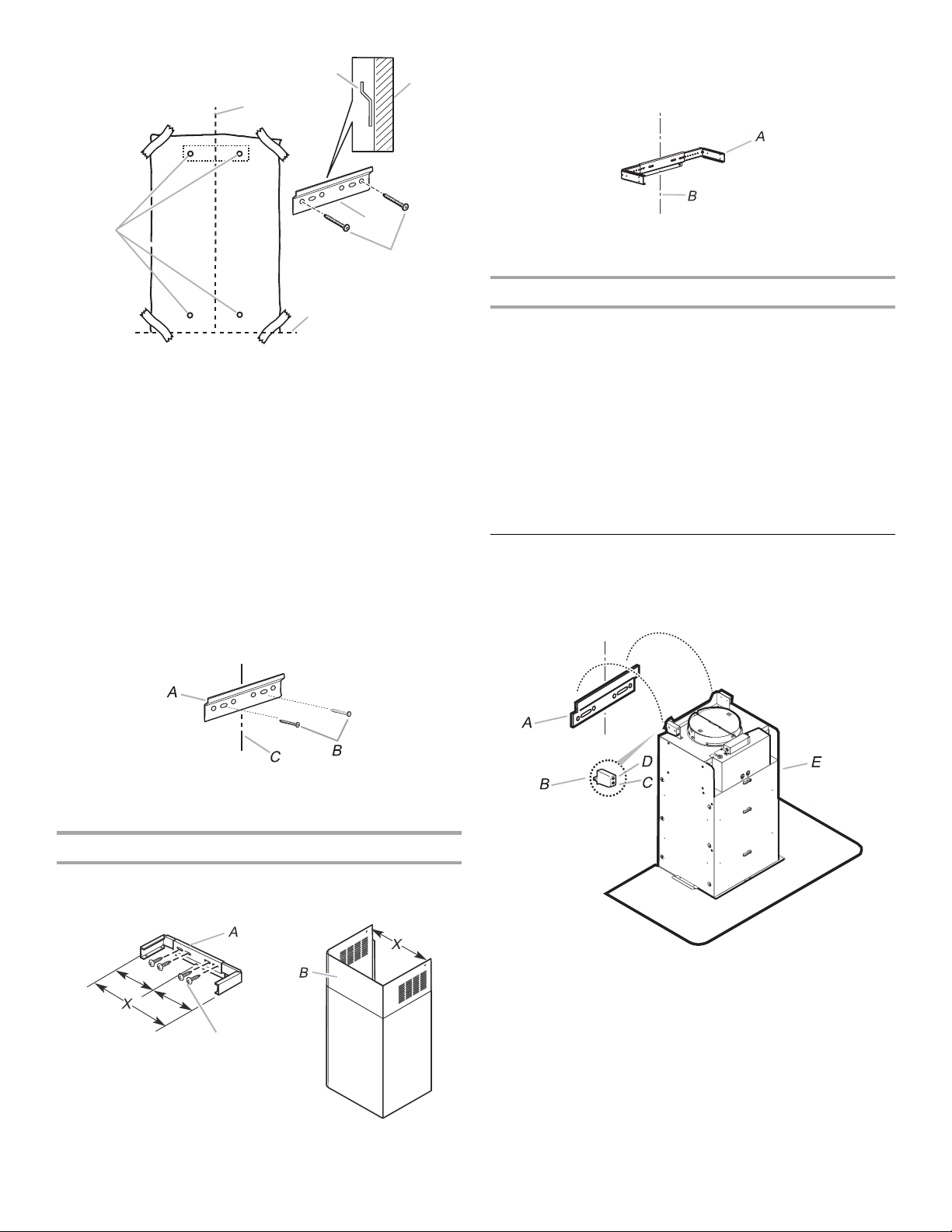
8. Place the support bracket on the template aligning it with the
traced rectangle. Mark centers of 4 fastener locations through
the template to the wall, 2 for support bracket, 2 for bottom
rear of blower housing.
IMPORTANT: All screws must be installed into wood.
Remove the template.
9. Drill ⁷⁄₆₄" (2.75 mm) pilot holes at all locations where screws
are being installed into wood.
NOTE: When mounting into a concrete wall, drill ⁵⁄₁₆" (8 mm)
pilot holes and use anchors supplied.
10. Attach the support bracket to the wall using 2 - 5 x 45 mm
screws at the top 2 drilled hole locations.
Vent Cover Bracket Assembly and Installation
1. Assemble the 3 pieces of the vent cover bracket using 4 -
4 x 8 mm screws provided. The assembled bracket should be
sized to dimension "X" to fit inside the upper vent cover.
2. Install vent cover bracket to wall about ¹⁄₈" (3.0 mm) away
from the ceiling. Use 2 - 5 x 45 mm screws with 8 x 40 mm
drywall anchors supplied.
Complete Preparation
1. Determine and make all necessary cuts in the wall for the vent
system. Install the vent system before installing the hood. See
“Venting Requirements” section.
2. Determine the required height for the home power supply
cable and drill a 1¼" (3.2 cm) hole at this location.
3. Run wire through the home power supply cable according to
the National Electrical Code or CSA Standards and local
codes and ordinances. There must be enough ½" conduit
and wires from the fused disconnect (or circuit breaker) box
to make the connection in the hood’s electrical terminal box.
NOTE: Do not reconnect power until installation is complete.
4. Use caulk to seal all openings.
Install Range Hood
1. Using 2 or more people, hang blower housing on lower
support bracket using the 2 mounting hooks on the rear of
the blower housing.
2. Level the blower housing with leveling screws in mounting
hooks, using a level across bottom of blower housing.
A. Centerline
B. Lower support bracket
C. 5 x 45 mm screws
D. Mounting height reference
E. Fastener locations
F. Wall
A. Support bracket
B. 5 x 45 mm screws
C. Centerline on wall
A. Vent cover bracket assembly
B. Upper vent cover
C. 4 x 8 mm screws
A
B
C
D
E
F
B
C
A. Vent cover bracket
B. Centerline on wall
A. Lower support bracket
B. Mounting hooks
C.Adjust in and out
(for leveling front to back).
D. Adjust up and down
(for leveling left to right).
E. Blower housing
Loading ...
Loading ...
Loading ...