Loading ...
Loading ...
Loading ...
WARNING – SERVICING TO BE CARRIED OUT ONLY BY AN AUTHORISED PERSON
Disconnect from electricity before servicing. Check appliance is safe when you have nished.
33
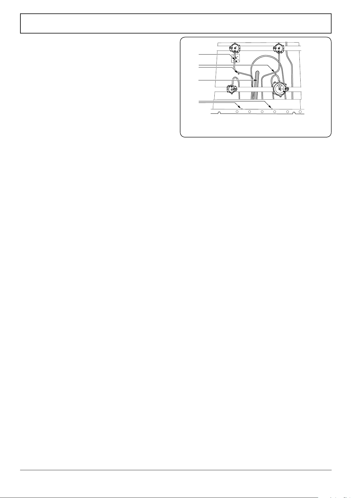
ArtNo.160-0008 - Bray grill burner fixing screws
A
C
D
B
A – Grill electrode plate xing screw, B – Position of grill burner
xing screws, C – Front shield xing screws, D – grill venturi
4 Grill
BEFORE SERVICING ANY GAS CARRYING
COMPONENTS, TURN OFF THE GAS SUPPLY.
4.1 To Change the Grill Control Tap
DISCONNECT FROM THE ELECTRICITY SUPPLY.
Remove the control panel (see 1.1). Lift up the right-
hand hotplate tray front (see 2.1). Undo the gas
connection to rear of valve and remove the screw(s)
securing tap to gas rail. Remove old tap, discard the old
gasket/seal. Fit the new gasket/seal to the new tap.
Reassemble in the reverse order. Check the tap is
adjusted for the correct gas. Check the appliance is gas
sound.
4.2 To Change the Grill Injector
DISCONNECT FROM THE ELECTRICITY SUPPLY.
Remove the control panel (see 1.1).
Lift up the spring clip retaining the grill injector holder
and slide the injector holder out of the burner venturi
(Fig.9-4). Remove the grill jet from adaptor and t a
new jet (see the ratings table for correct jet). Put the
injector holder back in the burner venturi.
4.3 To Change the Grill Burner
DISCONNECT FROM THE ELECTRICITY SUPPLY.
Remove the grill injector (see 4.2).
Remove the 2 screws holding the front shield and
remove the shield. Turn the grill venturi clockwise to
clear the front cross-member, lift up and remove
(Fig.9-5).
For models with ignition disconnect the electrode lead
and remove the screw holding the plate around the
grill electrode. Support the grill burner from below and
remove the 2 screws (under the foil wrap) securing grill
burner to the top of grill chamber. Remove the grill
burner.
Reassemble in reverse order taking care not to damage
the grill electrode (where tted).
4.4 To Change the Grill Electrode
DISCONNECT FROM THE ELECTRICITY SUPPLY.
Remove the grill burner (see 4.3). Withdraw the
electrode and pull o the electrode lead. Fit the lead to
the new electrode.
Reassemble in reverse order and check ignition is
satisfactory.
Fig.9-5
Loading ...
Loading ...
Loading ...