Loading ...
Loading ...
Loading ...
INSTALLATION
Check the appliance is electrically safe and gas sound when you have nished.
22
ArtNo.090-0018 - 90
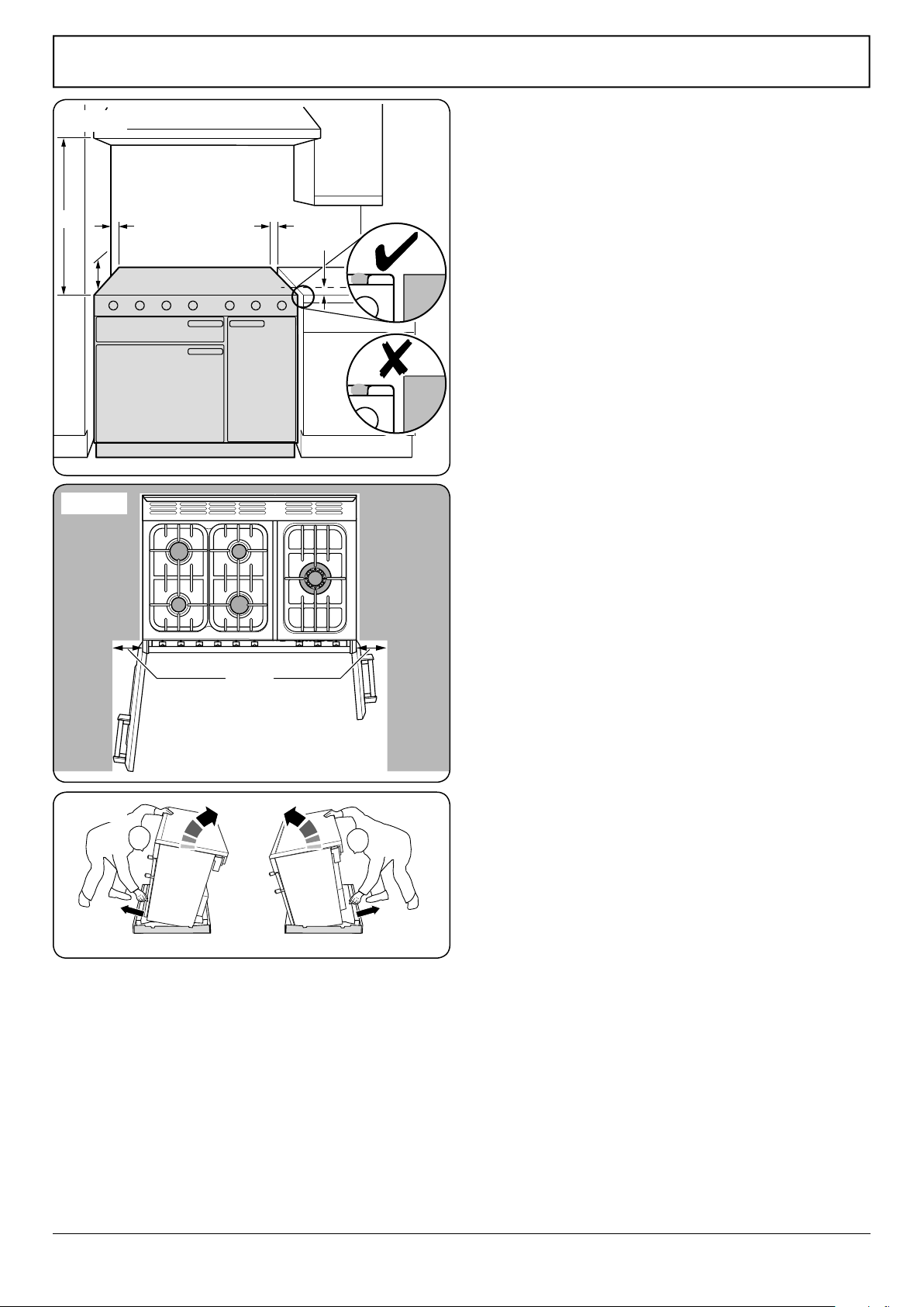
cooker clearances (AUS)
B
C
D
E
A
ArtNo.090-0025 - 90 classic (gas) door clearances
130 mm
Fig.7-1
Positioning the Cooker
The diagram (Fig.7-1) shows the minimum recommended
distance from the cooker to nearby surfaces as given in
AS 5601.
1. Overhead – Measurement A
The minimum height of any surface above the cooker is
650 mm above the hotplate.
Cookerhoods and exhaust fans shall be installed in
accordance with the manufacturer’s instructions. However, in
no case shall the clearance between the highest part of the
hob of the cooking appliance and a cookerhood be less than
650 mm or, for an overhead exhaust fan, 750 mm.
2. Side Clearances – Measurements B & C
Where B, measured from the periphery of the nearest burner
to any vertical combustible surface, or vertical combustible
surface covered with toughened glass or sheet metal, is less
than 200 mm, the surface shall be protected to make sure
that the combustible surface does not exceed 65 °C above
ambient*. Even with the surface protected, the dimension B
should not be less than 135 mm above hotplate level.
*The xing of 5mm thick ceramic tiles to the surface, or
attaching re resistant material to the surface and covering with
sheet metal with a minimum thickness of 0.4 mm to a height C
of not less than 150 mm above the hotplate, should satisfy this
requirement.
3. Side Clearances – Measurement D & E
Where D, the distance from the periphery of the nearest
burner to a horizontal combustible surface is less than
200 mm, then E shall be 10 mm or more, or the horizontal
surface shall be above the trivet.
A clearance of 130 mm is required if the cooker is near a
corner of the kitchen, to allow the oven doors to open
(Fig.7-2). The actual opening of the doors is slightly less, but
this allows for some protection of your hand as you open the
door.
We recommend a gap of 910 mm between units to allow
for moving the cooker. Do not box the cooker in it must still
be possible to move the cooker in and out for cleaning and
servicing.
Fig.7-2
Fig.7-3
Loading ...
Loading ...
Loading ...