Loading ...
Loading ...
Loading ...
15
GB
5. Drainagepipingwork
Outdoorunitdrainagepipeconnection
When drain piping is necessary, use the drain socket or the drain pan (option).
Drain socket PAC-SG61DS-E
Drain pan PAC-SH97DP-E
6. Electricalwork
M1
S
M2 M1
S
M2
TB3 TB7
D G
E
F
A
B
C
TB1
L
N
B1 B2
TBD1
1 2
3
C
A Power source
B Power supply for branch box
C Screw on the electrical component box
D Transmission line
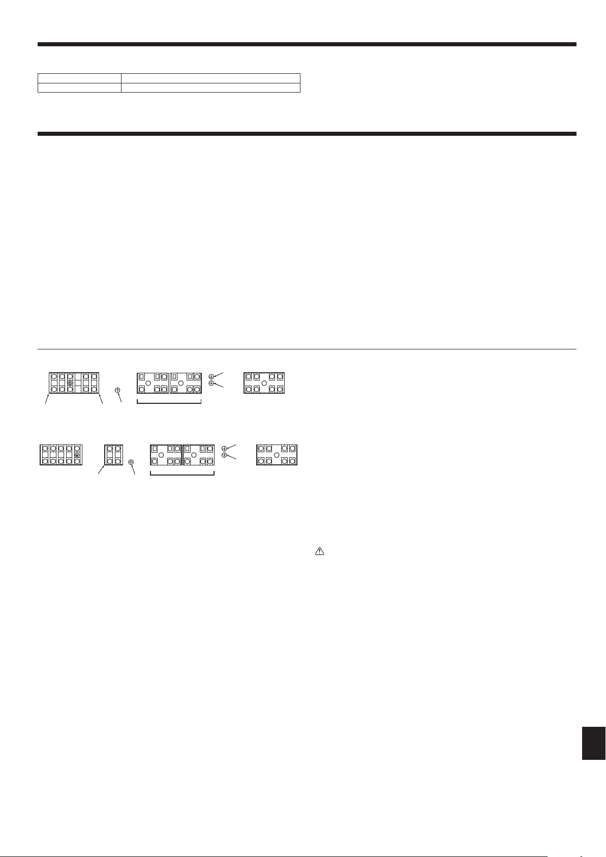
6.2. Controlboxandconnectingpositionofwiring
(Fig.6-1)
1. Connect the indoor unit transmission line to transmission terminal block (TB3), or
connect the wiring between outdoor units or the wiring with the centralized control
system to the centralized control terminal block (TB7).
When using shielded wiring, connect shield ground of the indoor unit transmission
line to the screw (F) and connect shield ground of the line between outdoor units
and the centralized control system transmission line to the shield (S) terminal of
the centralized control terminal block (TB7). In addition, in the case of outdoor
unitswhosepowersupplyconnectorCN41hasbeenreplacedbyCN40,theshield
terminal (S) of terminal block (TB7) of the centralized control system should also
be connected to the screw (F) using attached lead wire.
2. Conduit mounting plates(ø27)are being provided.Passthe power supplyand
transmission wires through the appropriate knock-out holes, then remove the
knock-out piece from the bottom of the terminal block and connect the wires.
3. Fix power source wiring to the terminal block by using buffer bushing for tensile
force (PG connection or the like).
4. The terminal block (TB1B) is for supplying power to the branch box (220
– 240
VAC. max 6 A).
5. The terminal block (TBD1) is for the input of the DRED signals (12 VDC, 1 mA).
Caution:
Neverconnectthetransmissionlinefortheindoorunitorthecentralizedcontrol
systemtransmissionlinetothisterminalblock(TB1B/TBD1).Ifthetransmission
linesareconnected,theindoorunitorcentralizedcontrolcouldbedamaged.
Fig.6-1
<PUMY-SP·VKMD>
M1
S
M2 M1
S
M2
TB3 TB7
B1 B2
TB1B
C
B
E
F
D
L1
L2 L3
N
TB1
A
G
TBD1
1 2
3
C
<PUMY-SP·YKMD>
E Ground for the terminal block (TB3)
F Screw on the electrical component box
G DRED signal input
6.1. Caution
1 Follow ordinance of your governmental organization for technical standard related
to electrical equipment, wiring regulations and guidance of each electric power
company.
2 Wiring for control (hereinafter referred to as transmission line) shall be (5 cm or
more)apartfrompowersourcewiringsothatitisnotinuencedbyelectricnoise
from power source wiring. (Do not insert transmission line and power source wire
in the same conduit.)
3 Be sure to provide designated grounding work to outdoor unit.
4 Give some allowance to wiring for electrical part box of indoor and outdoor units,
because the box is sometimes removed at the time of service work.
5 Neverconnectthemainpowersourcetoterminalblockoftransmissionline.If
connected, electrical parts will be burnt out.
6 Use2-core shield cablefortransmission line.Iftransmission lines ofdifferent
systems are wired with the same multiplecore cable, the resultant poor transmit-
ting and receiving will cause erroneous operations.
7 Onlythetransmissionlinespeciedshouldbeconnectedtotheterminalblockfor
outdoor unit transmission.
(Transmission line to be connected with indoor unit : Terminal block TB3 for
transmission line, Other : Terminal block TB7 for centralized control)
Erroneous connection does not allow the system to operate.
8 In case to connect with the upper class controller or to conduct group operation in
different refrigerant systems, the control line for transmission is required between
the outdoor units each other.
Connect this control line between the terminal blocks for centralized control. (2-
wire line with no polarity)
When conducting group operation in different refrigerant systems without connect-
ing to the upper class controller, replace the insertion of the short circuit connector
fromCN41ofoneoutdoorunittoCN40.
9 Group is set by operating the remote controller.
0 WhenconnectingtheCONNECTIONKIT(PAC-LV11M-J)andanM-seriesindoor
unit,refertotheinstallationmanualfortheCONNECTIONKIT.
1 When connecting a branch box, be sure to turn on the indoor units and the branch
box before turning on the outdoor unit.
2 Usethestrapontheunittosufcientlyfastenthecablesconnectedtothetermi-
nal blocks. In addition, make sure that the fastened cables and the strap do not
interfere with the panels.
RG79Y960H01.indb 15 2018/02/09 14:31:09
Loading ...
Loading ...
Loading ...