Loading ...
Loading ...
Loading ...
13
GB
4.3. Refrigerantpiping(Fig.4-10)
Remove the service panel D (three screws) and the front piping cover A (two screws)
and rear piping cover B(vescrews).
1 Performrefrigerantpipingconnectionsfortheindoor/outdoorunitwhentheoutdoor
unit’s stop valve is completely closed.
2 Vacuum-purge air from the indoor unit and the connection piping.
3 After connecting the refrigerant pipes, check the connected pipes and the indoor
unit for gas leaks. (Refer to 4.4. Refrigerant pipe airtight testing method)
4 Vacuumize the refrigerant lines through the service port of the liquid and gas stop
valves. And then open the stop valves completely (for both the liquid and gas stop
valves). This will completely connect the refrigerant lines of the indoor and outdoor
units.
• Ifthestopvalvesareleftclosedandtheunitisoperated,thecompressorand
control valves will be damaged.
• Usealeakdetectororsoapywatertocheckforgasleaksatthepipeconnec-
tion sections of the outdoor unit.
• Donotusetherefrigerantfromtheunittopurgeairfromtherefrigerantlines.
• Afterthevalveworkiscompleted,tightenthevalvecapstothecorrecttorque:
20to25N·m(200to250kgf·cm).
Failure to replace and tighten the caps may result in refrigerant leakage. In
addition, do not damage the insides of the valve caps as they act as a seal to
prevent refrigerant leakage.
5Usesealanttosealtheendsofthethermalinsulationaroundthepipeconnection
sections to prevent water from entering the thermal insulation.
4.4. Refrigerantpipeairtighttestingmethod
(1) Connect the testing tools.
• MakesurethestopvalvesA B are closed and do not open them.
• AddpressuretotherefrigerantlinesthroughtheserviceportC of the liquid
stop valve A and the gas stop valve B.
(2)Donotaddpressuretothespeciedpressureallatonce;addpressurelittlebylittle.
1 Pressurize to 0.5 MPa (5kgf/cm
2
G),waitveminutes, and make sure the
pressure does not decrease.
2 Pressurizeto1.5MPa(15kgf/cm
2
G),waitveminutes,andmakesurethe
pressure does not decrease.
3 Pressurizeto4.15MPa(41.5kgf/cm
2
G) and measure the surrounding tem-
perature and refrigerant pressure.
(3)Ifthespeciedpressureholdsforaboutonedayanddoesnotdecrease,thepipes
have passed the test and there are no leaks.
• Ifthesurroundingtemperaturechangesby1°C,thepressurewillchangeby
about0.01MPa(0.1kgf/cm
2
G). Make the necessary corrections.
(4) If the pressure decreases in steps (2) or (3), there is a gas leak. Look for the source
of the gas leak.
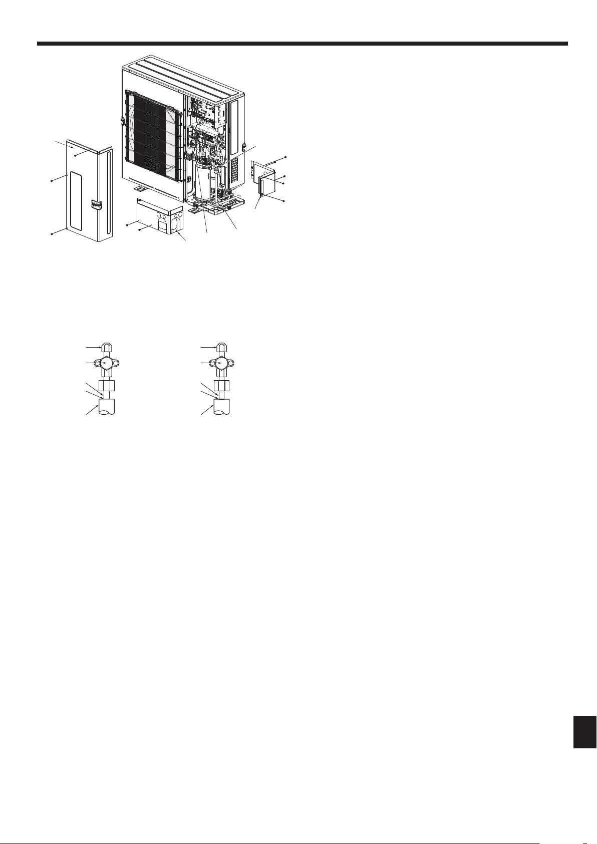
Fig.4-10
A Front piping cover
B Piping cover
C Stop valve
4. Installingtherefrigerantpiping
Fig.4-11
A Stopvalve<Liquidside>
B Stopvalve<Gasside>
C Service port
D Open/Closesection
E Local pipe
F Sealed, same way for gas side
G Pipe cover
A B
C
D
E
F
G
D
E
F
G
C
D Service panel
E Bend radius : 100 mm - 150 mm
F Strap
D
A
B
C
E
F
RG79Y960H01.indb 13 2018/02/09 14:31:08
Loading ...
Loading ...
Loading ...