User Manual
USING THE ICE MACHINE
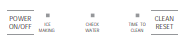
Controls
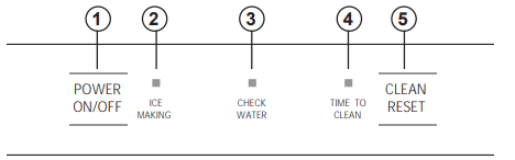
1. POWER ON/OFF - Press to turn the ice machine on or off.
2. ICE MAKING - Glows white when the unit is ON.
3. CHECK WATER - Glows red when there is not water supplied to the machine.
4. TIME TO CLEAN - Glows yellow when it's time to clean the machine. The light will switch ON after 6 months of use. It will remain on until the ice making system is cleaned using the process in the Care and Cleaning section.
5. CLEAN RESET - Pressed with Power button for 5 seconds to start the cleaning process (see Care and Cleaning).
Features
Starting the ice machine
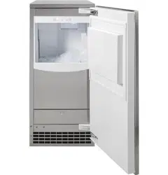
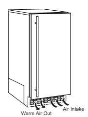
This machine takes in room temperature air at the lower right front and forces warm air out the lower left front. Restricting the airflow or operating the machine in a hot or cold environment will adversely affect the ability of the ice machine to make ice.
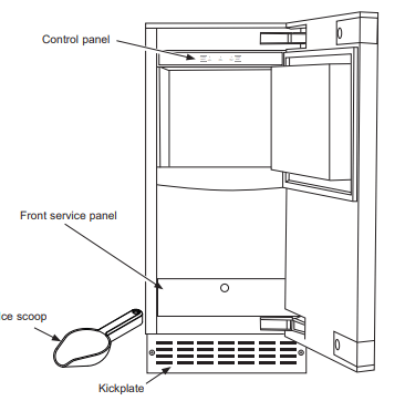
When the door is opened, the control panel, ice making area and ice storage bin are visible. The scoop is located in a holder along the right side wall.
This is a gravity drain model that must have a building drain connection below the level of the drain tube at the back of the cabinet. A pump can be installed, which can force drain water up a maximum of 10 feet, allowing it to be located where a gravity drain isn't available. See Accessories on page 21 for more information on the drain pump.
Initial Start Up
- Turn on the water supply.
- Switch on the electrical power.
- Push and release the ON/OFF switch to start the machine. The ICE MAKING light next to the ON/OFF switch will glow white.
It will take about 10 minutes for the ice machine to begin dropping nugget ice into the storage bin. It is normal for that ice to melt and continue to melt but at a slower rate as the bin cools. It will take about 6-7 hours to fill up the ice storage bin. The storage bin holds about 20 Ibs of ice when full.
Discard the first bin full of ice.
INSTALLATION INSTRUCTIONS
ICE MACHINE LOCATION AND PREPARATION
This ice machine is designed to be used indoors, in a controlled environment or outdoors within certain limits.
It is made up of two major systems: the ice making system and the ice storage system. The ice making system is a continuous flow that makes ice when the ice level becomes low and stops when it is full.
The ice storage system is an insulated chest with a drain at the bottom for melting ice. It is not refrigerated, insuring that the bin contains fresh ice.
During ice making, nugget ice will drop into the bin at an irregular rate; sometimes there will be little ice falling while other times a group of nuggets will fall.
IMPORTANT: Never keep anything in the ice storage bin that is not ice. Objects like wine or beer bottles are not only unsanitary, but the labels can slip off and plug up the drain.
IMPORTANT: Never allow the machine to operate without regular cleaning. The machine will last longer if it is Kept clean. Regular cleaning should happen at least once per year, and preferably twice. Some water conditions will dictate even more frequent cleaning of the ice making section, and some carpets or pets will dictate more frequent cleaning of the condenser.
Specifications
The ice machine will operate adequately within the limits, but functions best in temperatures between 60°F and 80°F.
- Minimum air temperature: 50°F (10°C)
- Maximum air temperature: 100°F (38°C)
- Minimum water temperature: 40°F (4.5°C)
- Maximum water temperature: 90°F. (32°C)
- Minimum water pressure: 20 psi (1.4 bar)
- Maximum water pressure: 80 psi (5.5 bar)
Electrical voltage limits:
See the Rating Plate inside the ice machine.
ADVANCE PLANNING
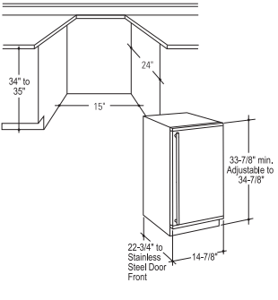
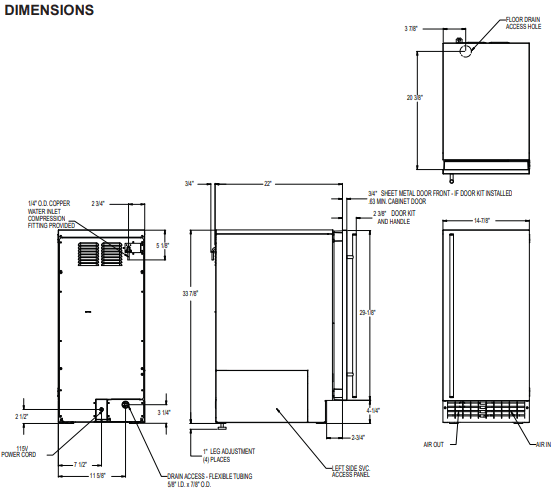
Cutout & Product Dimensions
Installation Notes
A drain pump is available for this ice machine. The drain pump kit number is UPK3 and is available at GEApplianceparts.com or by calling 877-959-8688. In Canada visit GEAppliances.ca or call 800.567.3344,
Built-In Installation: If a finished floor is to be installed in the area after the ice machine has been built in, shims the expected thickness of the floor should be installed under the unit to keep the machine level with the planned floor level.
NOTE: The water connection is at the back and adds a few inches to the cabinet depth.
Installation on a slab: You will need to install a drain pump to the appliance and pump the water to the point of drainage. See Accessories. Pumps will pump 1 story (10 feet) hight.
Installation over a crawl space or basement: Either a gravity drain or a pump may be used. For pump, see Accessories. If there is not enough room behind the machine for a drain/waste receptacle, the drain will have to be below the floor.
NOTE: When installed in a corner, the door swing may be limited due to handle contact with the wall or cabinet face.
A water supply is required. Water supplies vary in the degree of mineral content. High mineral content water will require more frequent maintenance. Water filtration may improve the taste of the ice as well as cut down on some of the mineral build up.
DOOR SWING
Moving the hinges allows the door to open from either the left or the right side. Change the swing BEFORE attaching the door panel.
To change:
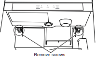
1. Open the door. Remove 4 stainless steel screws opposite the hinge side on the front of the cabinet.
2. Remove innermost screw holding each hinge to the cabinet. Loosen the other screw.
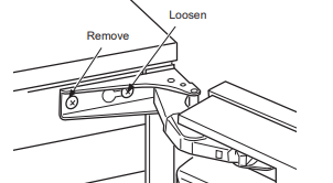
3. Slide the door to the side so the keyhole on thehinge clears the screw and remove from cabinet.
4. Remove the screws that were loosened and save. Install the 4 stainless steel screws that were removed in Step 1 into the open holes on the cabinet left by removing the hinge.
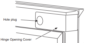
5. Remove the hole plug and hinge opening covers from door (if applicable).
6. Remove hole plugs or screws from unit's new hinge locations (if applicable). Set aside.
7. Install the 2 hinge screws removed after the door was removed from the cabinet into the outermost holes on the new hinge side of the cabinet. Screw these in only about half way.
8. Remove the upper hinge from the door and move it to the door's opposite side, bottom location. Secure using the original screws.
NOTE: If door panel is attached, it must be removed to access hinge screws and to reverse the handle position.
9. Remove the original lower door hinge and move it to the opposite side, upper location. Secure using original screws.
IMPORTANT: If installing a stainless steel door panel or custom panel, skip to INSTALLING THE DOOR PANEL section.
10. Install pocket covers and hole plugs onto door.
11. Place the keyhole slot on the hinge over the outermost screw, top and bottom, and slide the door onto the cabinet.
12. Install the door to the cabinet using the original screws. Tighten all 4 screws.
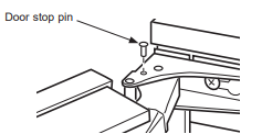
IMPORTANT: In some situations the door can open too far and damage adjacent cabinets. To prevent this, insert a Stop Pin (in hardware packet) into the provided hole in the top and bottom hinges.Drive the pin into the hole until the head is flush with the hinge.
13. Slide the hinge covers from the hardware packet over each hinge.

14. Attach the side covers from the hardware packet over the hinge by peeling off the covering over the adhesive and placing it over the side of the hinge.
NOTE: If the unit is being built-in a screw can be used to secure the unit to the cabinet in place of installing the side covers.
INSTALLING THE DOOR PANEL
The ice machine is supplied without a conventional door covering, allowing the attachment of a door panel or a custom panel.
NOTE: If the door swing is to be changed, itneeds to be done BEFORE attaching the door panel.
Door Panel
Finished door panels with handles are available from GE Appliances for attachment to the ice machine. See Accessories .
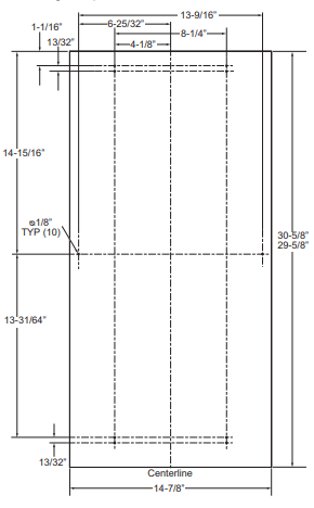
A custom panel of wood or other material not exceeding 15 lbs can be used and must follow these guidelines:
width: 14 7/8”
height: between 29 5/8” and 30 5/8”
thickness: 5/8” to 3/4”
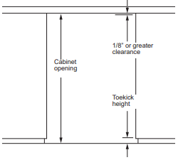
For Custom Panel:
- Measure overall height of the cabinet opening | where the ice machine will be installed (floor to bottom of the countertop edge).
- Determine desired toekick height (bottom of door to the floor). This can be equal to the adjacent cabinet’s toekick height.
- The clearance between the countertop and the top of the ice machine should be at least 1/8”.
- Subtract the toekick height and the clearance from the opening height to determine the height of your custom door panel.
5. Cut the panel to the specified width and height.
6. Determine the top of the panel. Measure and mark hole locations.
7. Drill pilot holes on the back of the panel at your markings. Use a drill stop to prevent drilling through the panel.
If the door swing is going to be changed please complete prior to installing the door panel. See page 11. Depending on the door kit being installed, the door handle may need to be flipped if the door swing is being changed. Please see instructions on how to flip the door handle.
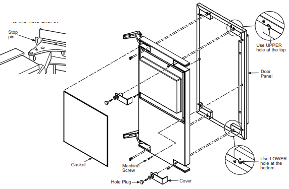
Attaching the Door Panel
The panel will be held on by 6 sheet metal screws and 2 machine screws.
- Remove the gasket from the inside of the door and retain for later use.
- Remove any plastic covering the stainless steel panel.
- Place the door panel onto the outside of the door and secure it with 2 machine screws in the left center and right center of the door.
- Fasten the panel to the door using the 6 sheet metal screws. In the hinge opening area opposite the hinge side, use the outermost screw holes only.
- Place the covers over the hinge opening areas and secure each cover to the door using a sheet metal screw and washer.
- Insert hole plug over screw installed in step 5.
- Return the gasket to its original position.
- Attach the door to the cabinet using the original using the original screws.
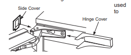
9. Slide the hinge covers from the hardware packet over each hinge.
10. Attach the side covers from the hardware packet over the hinge by peeling off the covering over the adhesive and placing it over the side of the hinge.
Note: If the unit is being built-in a screw can be secure the unit to the cabinet in place of installing the side covers.
11. Return the kickplate and front service panel to their original positions and attach to the cabinet using the original screws.
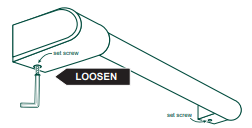
HANDLE REVERSING INSTRUCTIONS
1. Remove the allen wrench from the panel installation screw kit envelope
2. Loosen the set screw using the alien wrench
Remove the handle and flip it around so the logo is facing the other way.
3. Place the handle caps over the fasteners of the door. Take care to support the handle so it doesn’t fall and scratch the appliance finish. Make sure both handle caps are resting on the face of the door.
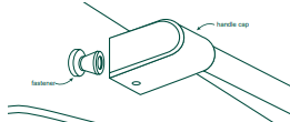
4. Lock one end of the handle into position by tightening the set screw in the handle cap with the allen wrench provided. DO NOT over-tighten.
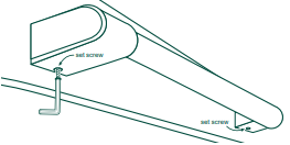
5. Keep supporting the handle as you lock the other end of the handle into position by tightening the set screw in the handle cap. DO NOT over-tighten.
PLUMBING - DRAIN PUMP
Drain Installation
A drain pump is available for this ice machine. The drain pump kit number is UPK3 and is available at GEApplianceparts.com or by calling GE Appliances at 877-959-8688. In Canada visit GEAppliances.ca or call 800.661.1616.
PLUMBING - GRAVITY DRAIN
Drain Installation
NOTICE Restrictions in the drain system to the machine will cause water to back up into the ice storage bin and melt the ice. Gravity drain tubing must be vented, have no kinks, and slope to the building drain. Air gaps are typically required by local codes.
- Place the ice machine in front of the installation opening. Adjust leveling legs to the approximate height. There are Leg Caps in the hardware packet that can snap onto the leveling legs if they are going to show when the unit is level.
- Insert drain tube through the routing hole in the back panel.
- Remove the upper back panel if needed for access to drain connection.
NOTE: If the drain opening has been located in the floor under the base pan according to the pre install specifications, follow steps 4 through 7 to drain the unit through the base. If not, proceed to step 7.
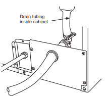
4. Remove the clamp and barbed elbow and take off the plastic cover in the base pan below the drain hose.
5. Connect a straight 5/8" barbed connector to the drain hose, securing with the supplied hose clamp.
6. Cutan 8"piece of 5/8" OD x 7/8" OD tygon (clear plastic) tubing. Slide one end of the tube onto the clamp, Leave the other end of the tube lying on the floor of the base pan until the unit is positioned over the floor drain.
7. Route the drain tube. Either a) insert the drain tube through the base pan into the floor drain or b)) route the drain tube through the hole in the lower back panel and connect to barbed elbow and secure with clamp.
8. Reinstall any panels removed to connect the drain.
Water Supply
The recommended water supply tubing is 1/4" OD copper. Stainless steel flex or reinforced PCV tube may also be used. Install an easily accessible shut- off valve between the supply and the unit. This shut- off valve should not be installed behind the unit.
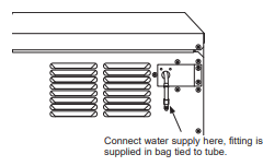
The water connection is at the back of the cabinet. Connect using a compression fitting, one is supplied tied to the water inlet tube at the back of the cabinet.
When built in: Coil enough tubing behind the machine so it can be pushed into the cavity without kinking the tubing.
PLACEMENT OF THE ICE MACHINE
The ice machine is supplied with a power cord. Do not remove the grounding pin from the cord's plug. Do not use extension cords. Follow all codes. Connect the machine so its own 115v, 15amp circuit.
- If the electrical outlet for the ice maker is behind the unit, plug it into the unit.
- Position the unit in the installation opening.
- Turn on the water supply. Make sure that the icemaker is plugged in and the power is on.
- Slide the unit into the installation opening, paying special attention to water supply and drain connections. Do not kink!
- Pour a couple of quarts of water into the ice storage bin; on drain pump equipped machines the drain pump should start and water should pump out. Check for leaks.
- Replace the service access panel.
- Level the unit as needed. There are Leg Caps in the hardware packet that can snap onto the leveling legs if they are going to show when the unit is level.
CARE AND CLEANING
Cleaning the Outside
The stainless steel door and door handle can be cleaned with a commercially available stainless steel cleaner. Cleaners with oxalic acid such as Bar Keepers Friend Soft Cleanser™ will remove surface rust, tarnish and small blemishes.
Use only a liquid cleanser free of grit and rub in the direction of the brush lines with a damp soft sponge. Do not use appliance wax or polish on the stainless steel.
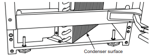
Cleaning the Condenser
The condenser has fins and tubes that can become clogged with dirt and lint.
To clean:
- Remove the kickplate and front service panel.
- Locate the condenser surface.
- Vacuum the surface to remove all dust and lint.
- Return the kickplate and front service panel to their original positions. Fasten them to the cabinet using the original screws.
Removing Scale from the Ice Making System
Cleaning the ice machine involves adding a solution of scale remover and water to the ice machine and continuing to add it as it makes ice. The scale remover must be diluted to the correct ratio. A squirt bottle will make adding the scale remover much easier when the unit is built in. If not built in, remove the top panel for reservoir access.
You should use rubber gloves when using the scale remover. To order scale remover, go to GEApplianceParts.com or call 877-959-8688. Order part number WX08X42872.
1. Scoop out and discard all of the ice.
2. Press and release the ON/OFF button.
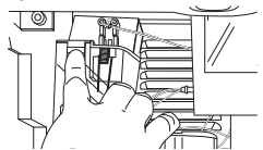
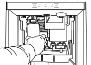
3. Open door and locate screws at the upper back wall of the bin. Remove the 2 screws.
4. Remove the back panel of the bin by lowering it down past the scoop holder. The scoop holder will rotate to allow the panel to lower.
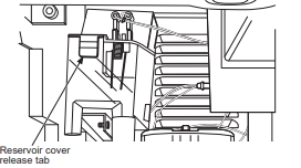
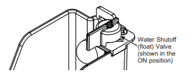
5. Water shutoff (float) valve is located at the back of the reservoir. The valve MUST be turned to the OFF position before the reservoir cover can be removed. Turn knob CCW 90°.
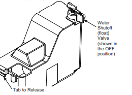
6.. Push tab on front edge of reservoir cover and remove the cover.
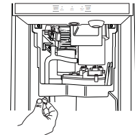
7. Locate the drain plug. Pull the drain plug out to drain the reservoir and evaporator. When draining is complete, return the plug to its original position.
8. Obtain pre-mixed scale remover solution or mix a solution of scale remover with water according to the directions. Fill a 16 oz squirt bottle with the diluted or pre-mixed scale remover.
NOTE: Take care not to spill any scale remover on nearby surfaces. Immediately wipe any spill with
9. Fill the reservoir with the scale remover solution from the squirt bottle. Use about half (8 0z) of the solution.
10. Press and HOLD both the CLEAN/RESET and ON/OFF buttons for 5 seconds. The TIME TO CLEAN light will blink on and off.
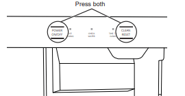
11. The auger motor will run for 10 minutes and then the compressor will start. Within 5-8 minutes the machine will start to make ice. The TIME TO CLEAN light will glow steady until the clean cycle is complete.
After the ice making starts, continuously add scale remover solution to the reservoir to keep it about half full.
When all 16 oz of the solution is used, turn the water shutoff (float) valve knob CW 90° to the ON position.
After 40 minutes, the ice machine and all the control panel lights will shut off.
12. Pull the drain plug again to drain the system and then replace it.
13. Turn the Water Shut Off (Float) Valve knob to the Off position, replace the reservoir cover, and then turn the Water Shut Off (Float) Valve knob back to the On position.
14. Replace the upper back wall of the bin using the original screws. Push in to snap bottom of back panel into place.
15. Pour a gallon of hot (95°-115°F) water into the bin to flush out the drain and melt all ice that was made during the cleaning process. Be sure all ice is melted.
16. Use any left over scale remover solution to scrub the scale off of the bin liner. If none is left over, use pre-mixed or mix 1 quart according to the directions.
17. Rinse the liner with hot water.
18. Sanitize the bin interior.
19 Push and release the ON/OFF button to restart ice making.
The ice scoop should be washed regularly and is dishwasher safe.
Other Maintenance
NOTE: It is normal for some lime scale to form on the gear reducer cover. Wipe up any loose scale.
Check the top bearing.
The top bearing is non-metallic and requires no lubrication. However, it should be checked for wear occasionally. The top of panel must be removed to access the bearing. The wear limit is 1/64". and can be checked with a pin gauge.
Winterizing
- Clean the ice making system per the instructions on pages 7 and 8.
- Open the door and push the ON/OFF button to turn the ice machine off.
- Turn off the water supply.
- Remove the back wall of the ice storage bin.
- Remove the drain plug and drain the water reservoir return plug to its original position.
- Models with a drain pump installed should have about 1/2 gallon of RV antifreeze (propylene glycol) poured into the ice storage bin drain.
- Turn off and unplug the machine.
NOTE: Automotive antifreeze must NOT be used.
TROUBLESHOOTING
Low capacity
- Restricted drain or standing water in the bin
- Clean the air cooled condenser fins.
- Clean the ice making system.
- Check the drain line for kinks
No ice
- Switch is OFF
- Press the ON/OFF button to turn the power on.
- Electric breaker has been tripped
- Flip the electric breaker back on.
- Water supply is low
- If the Check Water light is flashing Red, the water supply is low.
- Auger motor is not working or is overloaded - lights are flashing.
- Reset by pressing ON/OFF button. If this doesn't reset the motor and the lights continue to flash, call for service.
Time to Clean light is on
- Clean the ice making system following directions in the Care and Cleaning section.
Noise
The ice machine is designed for quiet operation but will make some noise during the ice making cycle.