Loading ...
Loading ...
Loading ...
12
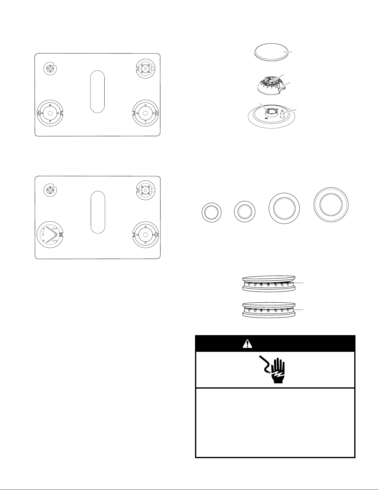
4. Remove cooktop burner caps and bases from package
containing parts. Place the burner bases as indicated by the
following illustration for your model:
For Models MGS8800F and WEG745H0F:
For Model KSGB900E:
A
D
EB
C
A. Small (Auxiliary)
B. Large (Ultra Rapid)
C. Oval (OV) D. Medium (Semi Rapid)
E. Large (Ultra Rapid)
A
D
C
EB
A. Small (Auxiliary)
B. X-Large (Stack)
C. Oval (OV) D. Medium (Semi Rapid)
E. Large (Ultra Rapid)
5. Align the gas tube opening in the burner base with the
orice holder on the cooktop and the igniter electrode
with the notch in the burner base.
6. Place the burner caps on the appropriate burner bases.
IMPORTANT: The bottom of the small and medium caps are
different. Do not put the wrong size burner cap on the burner
base. Each round burner cap is marked with an AUX, SR,
UR, or ST to match with a letter on the burner base.
7. Plug into a grounded 3 prong outlet.
A
B
C
D
E
A. Burner cap
B. Gas tube opening
C. Burner base
D. Igniter electrode
E. Orice holder
A
B
A. Incorrect
B. Correct
Electrical Shock Hazard
Plug into a grounded 3 prong outlet.
Do not remove ground prong.
Do not use an adapter.
Do not use an extension cord.
Failure to follow these instructions can result in death,
fire, or electrical shock.
WARNING
Burner caps should be level when properly positioned. If
burner caps are not properly positioned, surface burners
willnot light. The burner cap should not rock or wobble when
properly aligned.
NOTE: Each round burner base is marked with one of the
following: AUX, SR, UR, ST.
AUX
SR
ST
UR
Small cap
(Auxiliary)
Medium cap
(Semi Rapid)
Large cap
(Ultra Rapid)
X-Large cap
(Stack)
Loading ...
Loading ...
Loading ...