OWNER HANDBOOK
FIATPANDA

This Owner Handbook is intended to show the vehicle's operating conditions.
For the enthusiast user who wants to have insights, curiosities and detailed information about the characteristics and functions
of the vehicle, Fiat gives the opportunity to consult a dedicated section which is available in electronic format.
ONLINE VEHICLE OWNER HANDBOOK
The following symbol is reported within the text of the Owner Handbook, next to the subjects for which details are provided.
Go to the www.mopar.eu/owner
website and access your personal area.
The “Maintenance and care” page includes all the information about your vehicle and the link to access eLUM, where you will find
all the details of the Owner Handbook.
The eLUM website is free and will allow you, among many other things, to easily consult the on-board documents
of all the other vehicles of the Group.
Have a nice reading and happy motoring!

Dear Customer,
We would like to congratulate and thank you for choosing a Fiat Panda.
We have written this handbook to help you get to know all the features of your vehicle and use it in the best possible way.
Here you will find information, advice and important warnings regarding use of your vehicle and how to achieve the best performance
from the technical features of your Fiat Panda.
You are advised to read it right through before taking to the road for the first time, to become familiar with the controls and above all
with those concerning brakes, steering and gearbox; at the same time, you can understand the vehicle behaviour on different road
surfaces.
This document also provides a description of special features and tips, as well as essential information for the safe driving, care and
maintenance of your Fiat Panda over time.
After reading it, you are advised to keep the handbook inside the vehicle, for an easy reference and for making sure it remains on
board the vehicle should it be sold.
In the attached Warranty Booklet you will also find a description of the Services that Fiat offers to its customers, the Warranty
Certificate and the detail of the terms and conditions for maintaining its validity.
We are sure that these will help you to get in touch with and appreciate your new vehicle and the service provided by the people at
Fiat.
Enjoy reading. Happy motoring!
IMPORTANT
This Owner Handbook describes all versions of the Fiat Panda; please consider only the information relevant to your
vehicle’s trim level, engine and version. All data contained in this publication are purely indicative. FCA Italy S.p.A. can
modify the content of this publication at any time, for technical or commercial purposes. For further information, contact
a Fiat Dealership.
READ THIS CAREFULLY
REFUELLING
Petrol engines: only refuel with unleaded petrol with octane rating (RON) not less than 95 in compliance with the European specification
EN228. Using these mixtures may cause misfiring and driving issues, as well as damage fundamental components of the supply system.
Diesel engines: refuel only with Diesel fuel motor vehicles conforming to the European specification EN590. The use of other products or
mixtures may damage the engine beyond repair and consequently invalidate the warranty, due to the damage caused.
LPG engines: refuel only with LPG for motor vehicles conforming to the European specification EN589. The use of other products or
mixtures may damage the engine beyond repair and consequently invalidate the warranty, due to the damage caused.
For further details on the use of the correct fuel see the "Refuelling the vehicle" paragraph in the "Starting and driving" chapter.
STARTING THE ENGINE
Make sure that the handbrake is engaged and place the gear lever in neutral. Fully depress the clutch pedal, without pressing the accelerator,
then turn the ignition key to MAR and wait for the
warning light to switch off (and the warning light for Diesel versions); turn the
ignition key to AVV and release it as soon as the engine starts.
Versions with Dualogic gearbox: make sure that the handbrake is engaged and that the gear lever is in P (Parking) or N (Neutral), fully
depress the brake pedal, then turn the ignition key to AVV and release it as soon as the engine is started. .
PARKING ON FLAMMABLE MATERIAL
The catalytic converter develops high temperatures during operation. Do not park the car on grass, dry leaves, pine needles or other
flammable material: fire hazard.
RESPECTING THE ENVIRONMENT
The vehicle is fitted with a system that carries out a continuous diagnosis of the emission-related components in order to help protect the
environment.
ELECTRICAL ACCESSORIES
If, after buying the vehicle, you decide to add electrical accessories (with the risk of gradually draining the battery), contact a Fiat Dealership.
They can calculate the overall electrical requirement and check that the vehicle's electric system can support the required load.
SCHEDULED SERVICING
Correct maintenance of the car is essential for ensuring that it maintains its performance and its safety features, its environmental friendliness
and low running costs for a long time to come.
USE OF THE OWNER HANDBOOK
OPERATING INSTRUCTIONS
Each time direction instructions (left/right or forwards/backwards) about the vehicle are given, these must be intended as
regarding an occupant in the driver's seat. Special cases not complying with this rule will be specified as appropriate in the text.
The figures in the Owner Handbook are provided by way of example only: this might imply that some details of the image do
not correspond to the actual arrangement of your car. In addition, the Handbook has been conceived considering vehicles with
steering wheel on the left side; it is therefore possible that on vehicles with steering wheel on the right side, the position or
construction of some controls is not exactly mirror-like with respect to the figure.
To identify the chapter with the information needed you can consult the index at the end of this Owner Handbook.
Chapters can be rapidly identified with dedicated graphic tabs, at the side of each odd page. A few pages further there is a key
for getting to know the chapter order and the relevant symbols in the tabs. There is in any case a textual indication of the
current chapter at the side of each even page.
WARNINGS AND PRECAUTIONS
While reading this Owner Handbook you will find a series of WARNINGS to prevent procedures that could damage your
vehicle.
There are also PRECAUTIONS that must be carefully followed to prevent incorrect use of the components of the vehicle,
which could cause accidents or injuries.
Therefore, all WARNINGS and PRECAUTIONS must always be followed carefully.
WARNINGS and PRECAUTIONS are recalled in the text with the following symbols:
personal safety;
vehicle safety;
environmental protection.
NOTE These symbols, when necessary, are indicated besides the title or at the end of the line and are followed by a number.
That number recalls the corresponding warning at the end of the relevant section.
SYMBOLS
Some car components have coloured labels whose symbols indicate precautions to be observed when using this component.

A plate summarising these symbols can also be found under the bonnet.
VEHICLE CHANGES/ALTERATIONS
IMPORTANT Any change or alteration of the car might seriously affect its safety and road holding, thus causing accidents, in
which the occupants could even be fatally injured.

KNOWING YOUR CAR
KNOWING THE INSTRUMENT PANEL
SAFETY
STARTING AND DRIVING
IN AN EMERGENCY
SERVICING AND CARE
TECHNICAL DATA
MULTIMEDIA
INDEX
5

6
KNOWING YOUR CAR
In-depth knowledge of your new vehicle
starts here.
IThe handbook that you are reading
simply and directly explains how it
is made and how it works.
That’s why we advise you to read it
seated comfortably on board, so that
you can see immediately what is
described here for yourself.
DASHBOARD ................................. 8
KEYS .............................................. 9
IGNITION DEVICE ........................... 10
THE FIAT CODE SYSTEM ............... 10
DOORS........................................... 11
SEATS ............................................ 12
HEAD RESTRAINTS........................ 14
STEERING WHEEL ......................... 15
REAR VIEW MIRRORS.................... 15
EXTERIOR LIGHTS ......................... 16
INTERIOR LIGHTS .......................... 18
WINDOW WASHING....................... 19
CLIMATE CONTROL SYSTEM ........ 21
ELECTRIC WINDOWS .................... 25
BONNET......................................... 25
BOOT ............................................. 27
USB PORTS AND AUX INPUT ........ 28
SMARTPHONE DOCKING .............. 29
VERSION WITH LPG SYSTEM........ 30
VERSION WITH METHANE
SYSTEM (NATURAL POWER) ......... 32
7
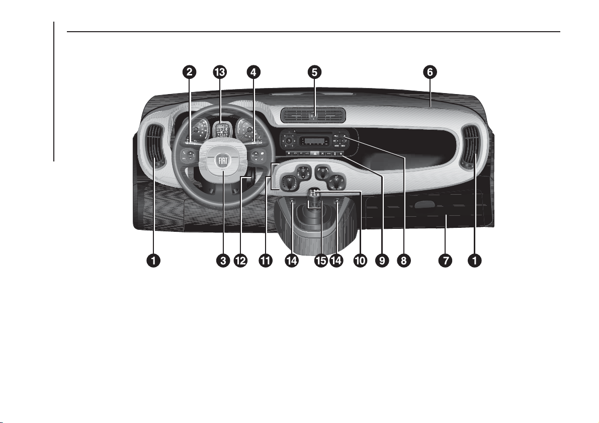
DASHBOARD
The presence and position of controls, instruments and gauges may vary depending on the versions.
1. Adjustable air vents 2. Exterior light control stalk 3. Driver front airbag 4. Windscreen wiper/rear window wiper/trip computer control lever
5. Adjustable and directable central air vents 6. Passenger front airbag 7. Glove compartment (for versions/markets, where provided) 8. Radio (for
versions/markets, where applicable) 9. Control buttons 10. Gear lever 11. Heating/ventilation/climate control system controls 12. Ignition device
13. Instrument panel 14. Front electric windows 15. ECO/ASR OFF buttons (for versions/markets, where provided)
1
F1D0131
8
KNOWING YOUR CAR
KEYS
MECHANICAL KEY
The metal insert of the key activates:
the ignition device, the driver's side and
passenger's side door locks (for
versions/markets where provided) and
the luggage compartment lock.
KEY WITH REMOTE
CONTROL
(for versions/markets, where provided)
1) 1) 1)
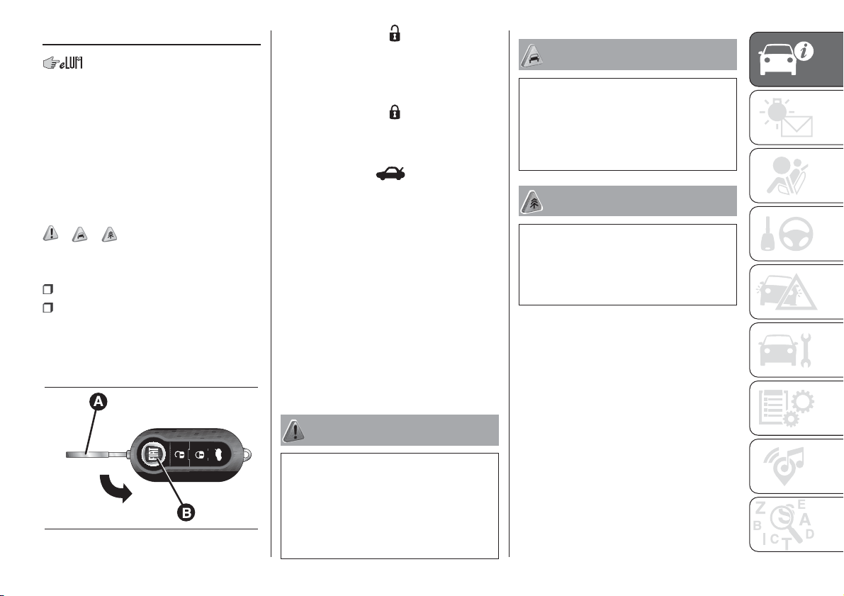
The metal insert A fig. 2 of the key
operates:
the ignition device;
the driver side door and, for
versions/markets where provided, the
passenger side door.
Press button B fig. 2 to open/close the
metal insert.
Briefly press button
: for unlocking of
doors and boot, timed switching-on
of ceiling lights and double flashing of
direction indicators (for versions/
markets, where provided).
Briefly press button
: lock of doors
and boot with ceiling lights off and
single flash of direction indicators (for
versions/markets, where provided).
Press the button
: remote
opening of the boot and double flashing
of the direction indicators. The
direction indicators will flash twice to
indicate that the boot has been
opened.
REQUEST FOR
ADDITIONAL KEYS
If you need a new mechanical key or a
new key with remote control, go to a
Fiat Dealership, taking an ID document
and the car ownership documents.
The system can recognise up to 8 keys
with incorporated remote control.
WARNING
1) Press button B only with the key far
from your body, especially your eyes and
from objects which could get damaged
(e.g. your clothes). Do not leave the key
unattended to avoid the button being
accidentally pressed while it is being
handled, e.g. by a child.
WARNING
1) The electronic components inside the
key may be damaged if the key is
subjected to strong shocks. In order to
ensure complete efficiency of the
electronic devices inside the key, it should
never be exposed to direct sunlight.
WARNING
1) Used batteries should be disposed of,
as specified by law, in the special
containers, otherwise take them to a Fiat
Dealership, which will deal with their
disposal.
2
F1D0005
9

IGNITION DEVICE
2) 3) 4) 5)
The key can be turned to 3 different
positions fig. 3:
STOP: engine off, key can be
removed, steering column locked.
Some electrical devices (e.g. audio
system, central door locking system,
etc.) can operate;
MAR: driving position. All electrical
devices are enabled;
AVV: engine starting.
The ignition device is fitted with a safety
system that requires the ignition key
to be turned back to STOP if the engine
does not start, before the starting
operation can be repeated.
STEERING LOCK
Activation
When the device is at STOP, remove
the key and turn the steering wheel until
it locks.
Turning off
Move the steering wheel slightly and
turn the key to MAR.
WARNING
2) If the ignition device has been tampered
with (e.g. an attempted theft), have it
checked by a Fiat Dealership before driving
again.
3) Always remove the key when you leave
your car to prevent someone from
accidentally operating the controls.
Remember to engage the handbrake.
Engage 1
st
gear if the car is parked uphill or
reverse if the car is parked downhill. Never
leave children unattended in the vehicle.
4) It is absolutely forbidden to carry out any
after-market operation involving steering
system or steering column modifications
(e.g.: installation of anti-theft device) that
could badly affect performance and safety,
invalidate the warranty and also result in
non-compliance of the car with type-
approval requirements.
5) Never remove the key while the car is
moving. The steering wheel will
automatically lock as soon as it is turned.
This holds true for cars being towed as
well.
THE FIAT CODE
SYSTEM
This is an electronic engine locking
system which increases protection
against attempted thefts of the car. It is
automatically activated when the
ignition key is removed.
OPERATION
Each time the vehicle is started by
turning the ignition key to MAR, the Fiat
CODE system control unit sends a
recognition code to the Powertrain
Control Module to deactivate the
immobiliser.
The code is sent only if the Fiat CODE
system control unit has acknowledged
the code received from the key.
Each time the ignition key is turned to
STOP, the Fiat CODE system
deactivates the functions of the engine
control module. If, during starting,
the code is not correctly recognised,
the
warning light switches on in the
instrument panel. In this case, turn
the key to STOP and then to MAR-ON;
if it is still locked, try again with the
other keys that come with the car.
Contact a Fiat Dealership if you still
cannot start the engine.
3
F1D0006
10
KNOWING YOUR CAR
If the warning light turns on, this
means that the system is running
a self-diagnosis (for example due to a
voltage drop). Should the fault persist,
contact a Fiat Dealership.
DOORS
LOCKING/UNLOCKING
DOORS FROM THE
INSIDE
Push the control lever A fig. 4 towards
the door to lock the doors or pull it
to unlock them. With central door
locking system (for versions/markets,
where provided), operating the lever
A on the driver's side will lock/unlock all
the doors. Operating lever A on the
other doors locks/unlocks only the door
concerned. With mechanical lock,
locking/unlocking takes place operating
the single control levers.
IMPORTANT The locked door condition
is indicated by the red printing B fig.
4.
LOCKING/UNLOCKING
DOORS FROM THE
OUTSIDE
Mechanical key: insert the metal
insert in the lock and turn it.
Key with remote control (for
versions/markets where provided):
press the
button to lock the doors, or
the
button to unlock the doors.
IMPORTANT Before opening a door,
ensure that you can do it in conditions
of safety. Open the doors only when the
vehicle is stationary.
CHILD SAFETY DEVICE
6)
This system prevents the rear doors
from being opened from the inside.
The device B fig. 5 can be engaged
only with the doors open:
position 1 - device engaged (door
locked);
position 2 - device not engaged
(door may be opened from the inside).
The device remains on even if the doors
are unlocked electrically.
IMPORTANT The rear doors cannot be
opened from the inside when the child
safety device is engaged.
4
F1D0029
11

WARNING
6) Always use this device when carrying
children. After engaging the child lock
on both rear doors, check for effective
engagement by trying to open a door with
the internal handle.
SEATS
FRONT SEATS
7) 8) 9) 10) 2)
Longitudinal adjustment
Lift lever A fig. 6 and push the seat
forwards or backwards: in the driving
position, you should be able to rest
your arms on the rim of the steering
wheel.
Height adjustment
(for versions/markets, where provided)
Adjust lever B fig. 6 upwards or
downwards to obtain the required
height.
IMPORTANT Carry out the adjustment
whilst seated in the driver's seat.
Backrest angle adjustment
Operate lever C fig. 7 to reach the
desired position, then release it.
Lumbar adjustment
(for versions/markets, where provided)
The position of the back against the
seat backrest is adjusted by turning
knob D fig. 8.
5
F1D0716
6
F1D0007
7
F1D0008
8
F1D0715
12
KNOWING YOUR CAR
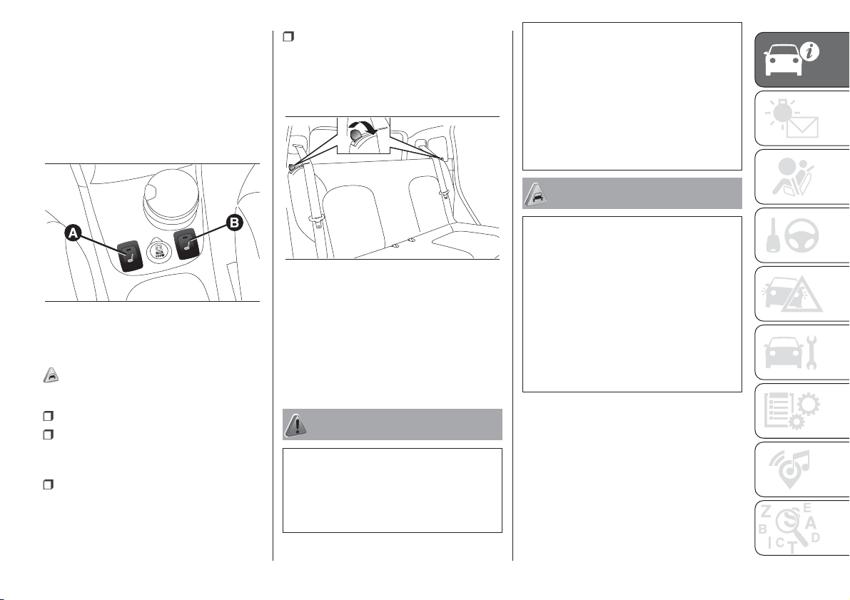
FRONT SEAT ELECTRIC
HEATING
(for versions/markets, where provided)
With the ignition key turned to MAR,
press button A or B fig. 9 respectively
to switch the function on.
To deactivate the function press the
button again.
REAR SEATS
Extending the boot
3)
Proceed as follows:
remove the rear shelf;
move the seat belts to the side,
making sure that they are correctly
extended and not twisted;
if there is a third rear seat (for
versions/markets, where provided),
release the central belt, winding the
buckle into its housing on the roof
panel;
operate the levers at the sides of the
rear seats fig. 10 pushing them
towards the inside of the vehicle, fold
the backrest and then bring the
backrest onto the cushion.
Repositioning the backrests
Move the seat belts to the side, making
sure that they are correctly extended
and not twisted. Lift up the backrest
folded previously until a click is heard
for the engagement mechanism.
WARNING
7) All adjustments must be made with the
car stationary.
8) If there is a side bag, it is dangerous to
use seat covers other than those available
from the MOPAR
®
Accessory Line.
9) Once you have released the adjustment
lever, always check that the seat is locked
on the guides by trying to move it back and
forth. Failure to lock the seat in place
could result in the seat moving suddenly
and the driver losing control of the car.
10) If passengers are seating in the rear
seats, remove all potentially dangerous
objects which may cause injuries in the
event of an accident.
WARNING
2) The fabric upholstery of the seats has
been designed to withstand long-term
wear deriving from normal use of the car.
Some precautions are however required.
Avoid prolonged and/or excessive rubbing
against clothing accessories such as
metal buckles and Velcro strips which, by
applying a high pressure on the fabric in
a small area, could cause it to break,
thereby damaging the upholstery.
3) Before tilting the backrest, remove any
objects on the seat cushion.
9
F1D0145
10
F1D0034
13
HEAD RESTRAINTS
11) 12)
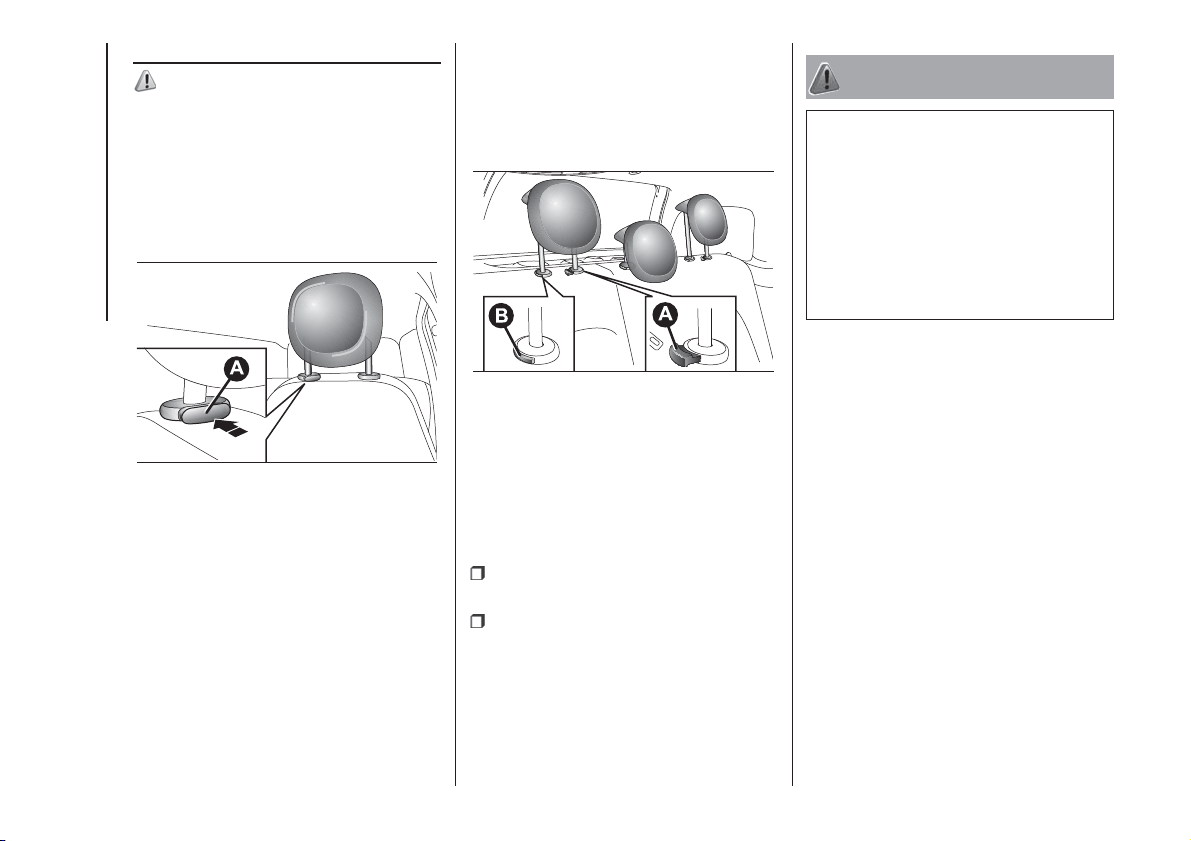
FRONT HEAD
RESTRAINTS
Upwards adjustment: raise the head
restraint until it clicks into place.
Downward adjustment: press button
A fig. 11 and lower the head restraint.
"Anti-Whiplash" device
The head restraints are equipped with
an “Anti-Whiplash” device, which
reduces the distance between head
and head restraint in the event of a rear
impact, thus mitigating the "whiplash"
effect.
The head restraint may move when the
backrest is pressed by the occupant’s
torso or hand: this behaviour is caused
by the system and should not be
considered a malfunction.
REAR HEAD RESTRAINTS
Upwards adjustment: raise the head
restraint until it clicks into place.
Downward adjustment: press button
A fig. 12 and lower the head restraint.
IMPORTANT If the rear seats are used,
always set the head restraints in the
"completely raised" position.
Removal
Proceed as follows to remove the head
restraints:
raise the head restraints to their
maximum height;
press buttons A and B fig. 12 at the
side of the two supports, then remove
the head restraints by pulling them
upwards.
WARNING
11) All adjustments must be made with the
car stationary. Head restraints must be
adjusted so that the head, rather than the
neck, rests on them. Only in this case
they can protect your head correctly.
12) To make the best use of the head
restraint's protective action, adjust the
backrest so that you are sitting upright and
keep your head as close as possible to
the head restraint.
11
F1D0011
12
F1D0012
14
KNOWING YOUR CAR
STEERING WHEEL
13) 14)
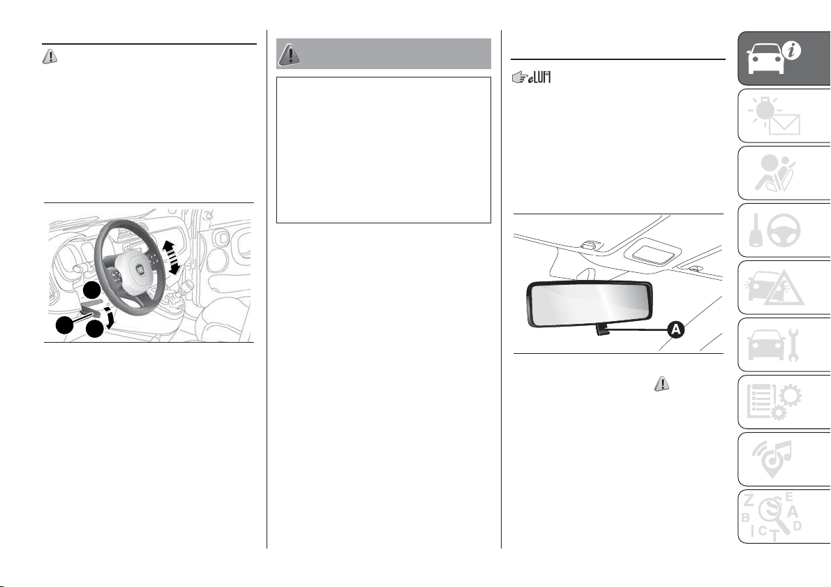
ADJUSTMENTS
The steering wheel can be adjusted
vertically.
To adjust it, move lever A fig. 13
downwards to position 1, then adjust
the steering wheel to the most suitable
position and lock it in position by
moving lever A to position 2.
WARNING
13) All adjustments must be carried out
only with the car stationary and engine off.
14) It is absolutely forbidden to carry out
any after-market operation involving
steering system or steering column
modifications (e.g.: installation of anti-theft
device) that could badly affect performance
and safety, invalidate the warranty and
also result in non-compliance of the car
with type-approval requirements.
REAR VIEW
MIRRORS
REAR-VIEW MIRROR
The mirror is fitted with a safety device
that causes its release in the event of
a violent impact with the passenger.
Operate lever A fig. 14 to adjust the
mirror into two different positions:
normal or anti-glare.
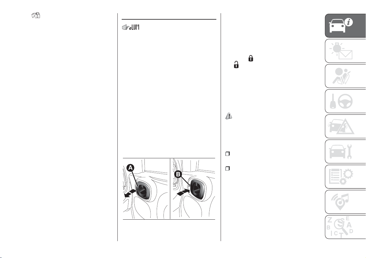
DOOR MIRRORS
15)
Manual adjustment
From the inside of the car, operate lever
A fig. 15 to adjust the mirror.
Electric adjustment
(for versions/markets, where provided)
The mirrors can only be adjusted with
the ignition key at MAR.
A
2
1
13
F1D0013
14
F1D0014
15

To carry out the adjustment, proceed as
follows:
select the desired mirror (left or right)
using selector A fig. 16;
move selector A to position B and
manipulate it to adjust the left door
mirror;
move selector A to position D and
manipulate it to adjust the right door
mirror.
Once you have finished the adjustment,
return selector A to intermediate
locking position C.
IMPORTANT When the heated rear
window is activated, door mirror
defrosting is activated (for versions/
markets, where provided).
Manual folding
When required, fold the mirrors toward
the car interior.
IMPORTANT While driving , the mirrors
must always be open.
WARNING
15) As the driver's door mirror is curved, it
may slightly alter the perception of
distance.
EXTERIOR LIGHTS
The left stalk fig. 17 controls the
operation of the headlights, side lights,
dipped beam headlights, parking lights,
main beam headlights, direction
indicators, and "Follow me home"
device.
The exterior lights can only be switched
on when the ignition key is at MAR.
The instrument panel and the various
dashboard controls will come on with
the external lights.
15
F1D0015
16
F1D0016
A
17
F1D0019
16
KNOWING YOUR CAR
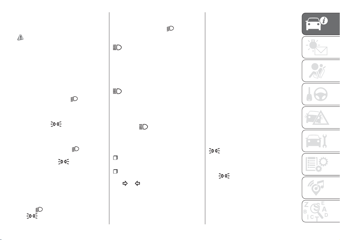
SIDE LIGHTS / DAYTIME
RUNNING LIGHTS (DRL)
"Daytime Running Lights"
(for versions/markets, where provided)
16) 17)
With the ignition key in MAR position
and the ring nut A fig. 17 turned to
O position, the daytime lights switch on
automatically; the other lights and the
internal lighting remain off.
SIDE LIGHTS / DIPPED
BEAM HEADLIGHTS
With the ignition key turned to MAR,
turn ring nut A fig. 17 to
. If dipped
beam headlights are activated, the
daytime running lights switch off and
the side lights and dipped headlights
switch on. The
warning light
switches on in the instrument panel.
When the ignition key is turned to the
STOP position or removed and ring A is
turned from the O to the
position,
all the side lights and number plate
lights turn on. The
warning light
will come on in the instrument panel.
PARKING LIGHTS
These lights can only be turned on with
ignition key in STOP position or
removed, by moving the ring nut A fig.
17 first to position O and then to
position
.
The
warning light switches on in
the instrument panel.
MAIN BEAM HEADLIGHTS
To activate the main beam headlights,
with ring nut A fig. 17 at
, pull the
stalk towards the steering wheel
beyond the end of travel position. The
warning light switches on in the
instrument panel.
When the stalk is pulled towards the
steering wheel again, beyond the end
of travel position, the main beam
headlights deactivate, the dipped
headlights reactivate and the
warning light switches off.
FLASHING
To do this, pull the stalk towards the
steering wheel (unstable position),
regardless of the position of ring nut A
fig. 17. The
warning light switches
on in the instrument panel.
DIRECTION INDICATORS
Place the lever in the (stable) position:
upwards: activates the right
direction indicator;
downwards: activates the left
direction indicator.
The
or warning light will blink on
the instrument panel. The direction
indicators switch off automatically when
the steering wheel is straightened.
"Lane Change" function
If you wish to signal a lane change,
place the left stalk in the unstable
position for less than half a second. The
direction indicator on the side selected
will be activated for 5 flashes and
then go out automatically.
"FOLLOW ME HOME"
DEVICE
This allows the space in front of the car
to be lit for a set time.
Activation: with the ignition key on
STOP or removed, pull the stalk
towards the steering wheel within 2
minutes from when the engine is turned
off.
Each time the stalk is moved, the lights
stay on for an extra 30 seconds up to
a maximum of 210 seconds; then
the lights are switched off automatically.
Each time the stalk is operated, the
warning light on the instrument
panel switches on and the display also
shows a message and how long the
function will remain active.
The
warning light comes on when
the stalk is first operated and stays on
until the function is automatically
deactivated. Each time the stalk is
activated it increases the time that the
lights remain on.
17
Deactivation: keep the stalk pulled
towards the steering wheel for more
than two seconds.
REAR FOG LIGHTS
Press the
button, on the dashboard,
to switch on the rear fog lights.
With rear fog lights on, the
warning
light on the instrument panel will come
on at the same time.
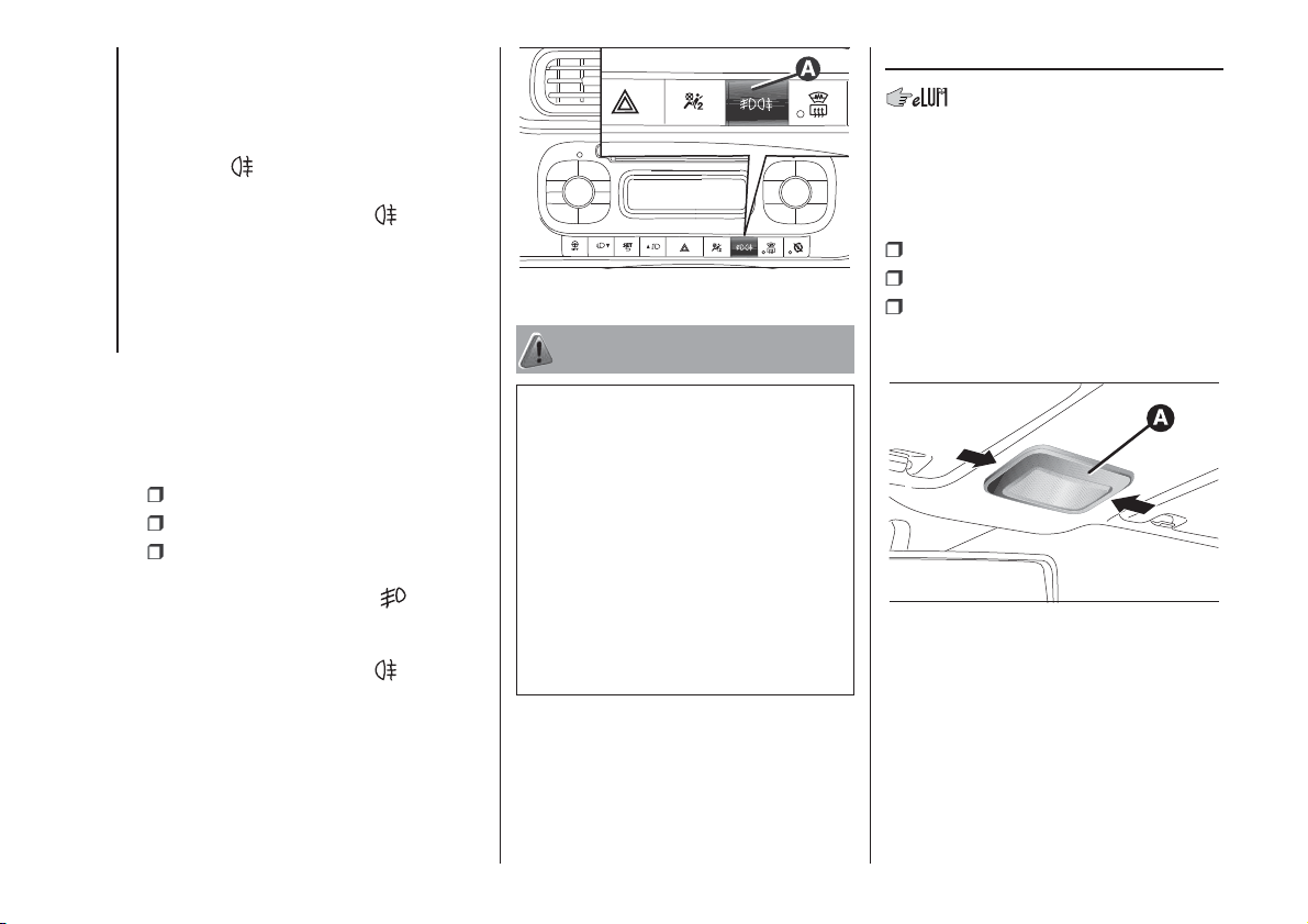
FRONT/REAR FOG
LIGHTS
(for versions/markets, where provided)
The fog lights can be activated only
when the dipped beam headlights are
on.
To turn on the front/rear fog lights,
press button A fig. 18 as follows:
First pressing: front fog lights on;
second press: rear fog lights on;
third pressing: front/rear fog lights
off.
With front fog lights on, the
warning
light on the instrument panel will come
on at the same time.
With rear fog lights on, the
warning
light on the instrument panel will come
on at the same time.
WARNING
16) The daytime running lights are an
alternative to the dipped beam headlights
for driving during the daytime in countries
where it is compulsory to have lights on
during the day, and they are also permitted
in those countries where this is not
obligatory.
17) Daytime running lights cannot replace
dipped beam headlights when driving at
night or through tunnels. The use of
daytime running lights is governed by the
Highway Code of the country in which you
are driving. Comply with legal
requirements.
INTERIOR LIGHTS
FRONT CEILING LIGHT
Singe-bulb roof light
The lens of ceiling light Afig. 19 can be
set to three positions:
right side pressed: light always on
left side pressed: light always off
central position: the light switches
on/off when the doors are opened/
closed.
18
F1D0024
19
F1D0021
18
KNOWING YOUR CAR
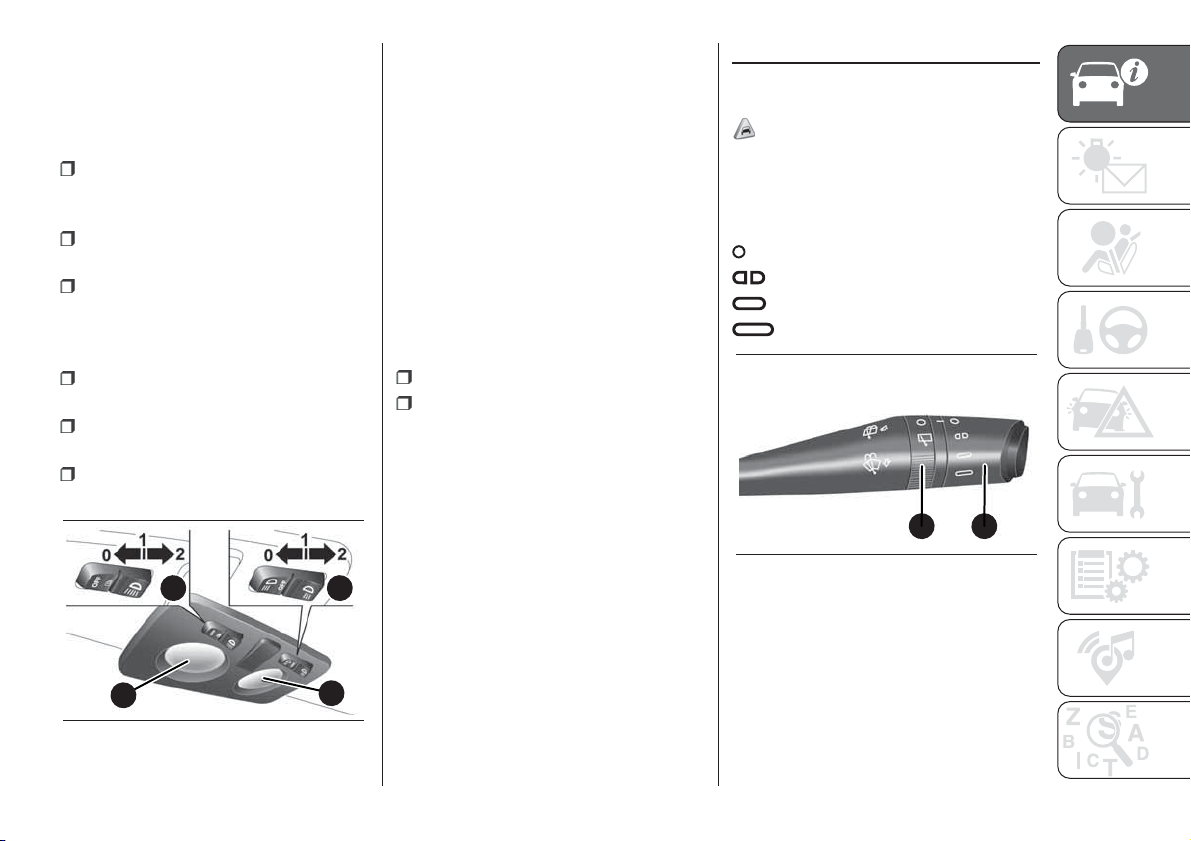
Multi-bulb roof light
(for versions/markets, where provided)
Switch A fig. 20 is used to switch on/off
the roof light bulbs.
A switch positions:
central position (position 1): lights C
and D switch on/off when the doors
are opened/closed;
pressed to the left (position 0): lights
C and D are always switched off;
pressed to the right (position 2):
lights C and D are always switched on.
The lights switch on/off gradually.
Switch B positions fig. 20:
central position (position 1): lights C
and D are always switched off;
pressed to the left (position 0): light
C switches on;
pressed to the right (position 2): light
D switches on.
IMPORTANT Before getting out of the
vehicle, make sure that both switches
are in the central position: when the
doors are closed the lights will switch
off to avoid draining the battery. In
any case, if the switch is left in the on
position, the roof light switches off
automatically about 15 minutes after
the engine has been switched off.
ROOF LIGHT TIMING
On certain versions, to facilitate getting
in/out of the vehicle at night or in
poorly-lit areas, two timed modes have
been provided.
when getting into the car;
when getting out of the vehicle.
WINDOW WASHING
WINDSCREEN WIPER /
WASHER
4) 5) 6)
This operates only with the ignition key
turned to MAR.
Ring nut A fig. 21 has four different
positions:
windscreen wiper off.
intermittent operation.
continuous slow operation.
continuous fast operation.
Move the stalk upwards (unstable
position) to limit operation to the time
for which the stalk is held in this
position. When released, the stalk will
return to its default position and the
windscreen wiper will be automatically
stopped.
C
A B
D
20
F1D0022
B A
21
F1D0020
19
With ring nut A fig. 21 in position,
the windscreen wiper will automatically
adapt its operating speed to the speed
of the car.
With the windscreen wipers
operational, if reverse gear is engaged,
the rear window wiper is automatically
activated.
“Smart washing” function
Pull the stalk towards the steering
wheel (unstable position) to operate the
windscreen washer.
Keeping the stalk pulled for more than
half a second, with just one movement
it is possible to operate the washer
jet and the wiper at the same time.
The windscreen wiper stops working
three strokes after the stalk is released.
A further stroke after approx. 6 seconds
completes the wiping cycle.
REAR WINDOW
WIPER/WASHER
4) 5) 6)
This operates only with the ignition key
turned to MAR.
Turn ring 1 fig. 21 from position O to
position
to operate the rear window
wiper as follows:
in intermittent mode when the
windscreen wiper is not operating;
in synchronous mode (at half the
speed of the windscreen wiper) when
the windscreen wiper is operating;
in continuous mode with reverse
gear engaged and the control active.
With the windscreen wiper on and
reverse gear engaged, rear window
wiping will be continuous.
Pushing the stalk towards the
dashboard (rocking position) will
activate the rear window washer jet.
Keep the stalk pushed for more than
half a second to activate the rear
window wiper as well. Releasing the
stalk will activate the smart washing
function, as described for the
windscreen wiper.
The function stops when the stalk is
released.
WARNING
4) Do not use the windscreen or rear
screen wiper to free the windscreen or rear
screen of accumulated layers of snow or
ice. In such conditions, the windscreen
or rear screen wiper may be subjected to
excessive stress and the motor cut-out
switch may trip, preventing operation for a
few seconds. If operation is not restored
(even after turning the key and restarting
the engine), contact a Fiat Dealership.
5) Do not operate the windscreen or rear
screen wiper with the blades lifted from the
windscreen or rear screen.
6) Make sure the device is switched off
whenever the windscreen or rear screen
must be cleaned.
20
KNOWING YOUR CAR
CLIMATE CONTROL SYSTEM
.
18) 2)
.
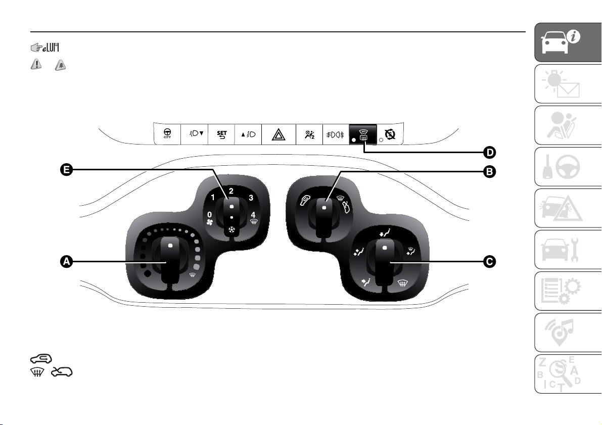
HEATER / MANUAL CLIMATE CONTROL SYSTEM
(for versions/markets, where provided)
Controls
A - Air temperature adjustment knob (red-hot / blue-cold).
B - Air recirculation knob:
internal air recirculation.
air intake from outside.
1
0
2
3
4
22
F1D0132
21

IMPORTANT It is advisable to switch the air recirculation on whilst queuing or in tunnels, or whilst driving on dusty roads, to
prevent the introduction of polluted air. However, it is better not to use the function for long periods, particularly if there are
many people on board, to prevent the windows from misting.
C - Air distribution knob:
air flow to central and side dashboard vents to ventilate the chest and the face during the hot season.
distribution between feet area diffusers (warmest air) and dashboard diffusers (coolest air).
towards the footwell diffusers. Due to the natural tendency of heat to spread upwards, this type of distribution warms the
passenger compartment up as quickly as possible, providing an immediate feeling of warmth.
distribution between feet area diffusers and windscreen/front side window diffusers. This type of distribution achieves
effective heating of the passenger compartment and prevents the windows from misting up.
air flow to the windscreen and front side window diffusers to demist or defrost them.
D - Heated rear window, folding mirror/heated windscreen (for versions/markets, where available) activation/deactivation
button. The LED on the button switches on to indicate activation. To maintain battery efficiency, the function is automatically
deactivated after about 20 minutes
E - Fan speed and climate control system activation/deactivation knob (for versions/markets, where available).
IMPORTANT In warm-humid weather conditions, using cold air on the windscreen may cause external condensation, which
could limit visibility.
NOTE To stop the air flow from the vents, position the knob at 0 and put knob B to internal air recirculation.
.
ADDITIONAL HEATER
(for versions/markets, where provided)
This device speeds up passenger compartment warming when it is very cold. The heater switches on automatically according
to the environmental conditions, with engine started and when the temperature of the engine coolant is low. The additional
heater turns off automatically after the required comfort conditions are achieved.
The heater only operates if the outside temperature and engine coolant temperature are low. The heater will not activate if the
battery voltage is too low.
22
KNOWING YOUR CAR
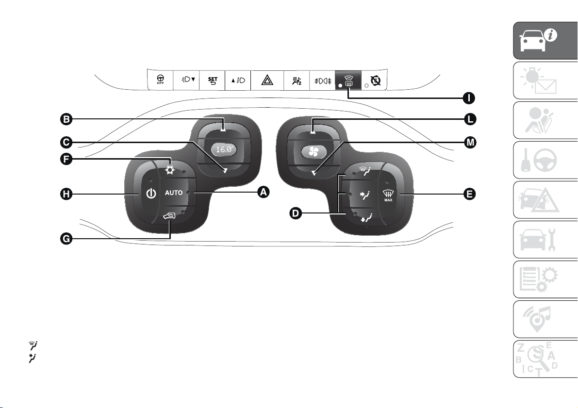
AUTOMATIC CLIMATE CONTROL SYSTEM
(for versions/markets, where provided)
Controls
.
A - Turns on the AUTO function (climate control system automatic operation).
B - Increases the air temperature.
C - Decreases the air temperature.
D - Selects manual air distribution.
By pressing the buttons, one of the five possible air flow distribution patterns can be selected:
air flow to the windscreen and front side window diffusers to demist or defrost them.
air flow to central and side dashboard vents to ventilate the chest and the face during the hot season.
23
F1D0708
23
towards the footwell diffusers. Due to the natural tendency of heat to spread upwards, this type of distribution warms the
passenger compartment up as quickly as possible, providing an immediate feeling of warmth.
+
distribution between feet area diffusers (warmest air) and dashboard diffusers (coolest air).
+
distribution between feet area diffusers and windscreen/front side window diffusers. This type of distribution achieves
effective heating of the passenger compartment and prevents the windows from misting up.
IMPORTANT In warm-humid weather conditions, using cold air on the windscreen may cause external condensation, which
could limit visibility.
E - Turns on/off the MAX-DEF function (fast front window defrosting/demisting).
F - Turns on/off the air conditioning compressor.
G - Turns on/off the internal air recirculation.
H - Climate control on/off.
F - Turns on/off the heated rear window and (for versions/markets, where available) the heated mirrors/heated windscreen.
L/M - Adjusts the fan speed.
The automatic climate control manages the Start&Stop function (engine off when the car speed is zero) to guarantee a suitable
comfort inside the passenger compartment.
NOTE In particularly severe climate conditions it is recommended to limit the use of the Start&Stop function to prevent the
compressor from continuously switching on and off, with consequent rapid misting of the windows and accumulation of
humidity with unpleasant smells in the passenger compartment.
.
WARNING
18) It is advisable not to use the air recirculation function when the outside temperature is low to prevent the windows from rapidly misting up.
WARNING
2) The system uses a coolant that is compatible with the laws in force in countries where the vehicle is sold, R134a or R1234yf. When
charging, only use the gas indicated on the dedicated plate in the engine compartment . The use of other coolants affects the efficiency and
condition of the system. The lubricant used for the compressor is also strictly linked to the type of cooling gas, please refer to a Fiat
Dealership.
24
KNOWING YOUR CAR
ELECTRIC WINDOWS
ELECTRIC FRONT
WINDOWS
19) 20)
These operate when the ignition key is
turned to MAR and for about three
minutes after turning the ignition key to
STOP or removing it.
The electric window control buttons are
located beside the gear lever fig. 24
and activate:
A Opening/closing of the left window.
B Opening/closing of the right
window.
With the ignition key at MAR, a long
press activates the automatic operation
of the window: raising/lowering on the
driver's side and lowering only on
the passenger side.
MANUAL REAR WINDOW
WINDERS
To open/close the window operate the
handle on the door panel.
WARNING
19) Improper use of the electric windows
can be dangerous. Before and during
operation, always check that passengers
are not exposed to the risk of being injured
either directly by the moving windows or
through objects getting caught or struck by
them.
20) When leaving the vehicle, always
remove the ignition key to avoid the risk of
injury for people still on board due to
accidental operation of the electric
windows.
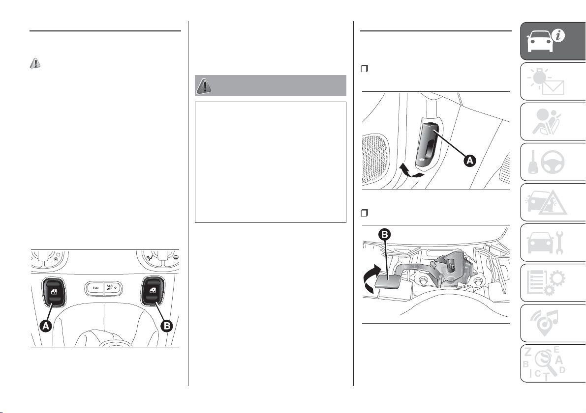
BONNET
OPENING
Proceed as follows:
pull lever A fig. 25 in the direction
indicated by the arrow;
move lever B fig. 26 to the left;
24
F1D0031
25
F1D0035
26
F1D0036
25
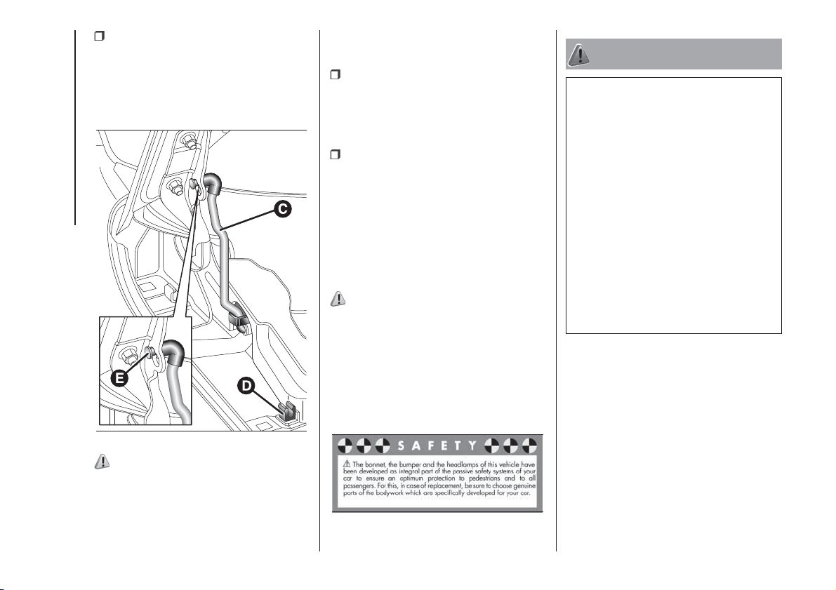
lift the bonnet and, at the same time,
release the supporting rod C fig. 27
from its catch D, then insert the end of
the rod into housing E in the bonnet
(large hole) and push to safety position
(small hole).
21) 22)
CLOSING
Proceed as follows:
keep the bonnet raised with one
hand and remove rod C fig. 27 from
housing E with the other, inverting the
opening motion, then fit it back into
its catch D;
lower the bonnet to approximately
20 centimetres from the engine
compartment and let it drop. Make sure
that the bonnet is completely closed
and not only fastened by the locking
device by trying to open it. If it is not
perfectly closed, do not try to press the
bonnet lid down but open it and repeat
the procedure.
23) 24)
IMPORTANT Always check that the
bonnet is closed correctly to prevent it
from opening while the vehicle is
travelling.
The following plate fig. 28 is applied
inside the engine compartment:
WARNING
21) Incorrect positioning of the supporting
rod may cause the bonnet to drop
suddenly.
22) Use both hands to lift the bonnet.
Before lifting, check that the windscreen
wiper arms are not raised from the
windscreen, that the vehicle is stationary
and that the handbrake is engaged.
23) Perform these operations only with
vehicle stationary.
24) For safety reasons, the bonnet must
always be properly closed while driving.
Therefore, make sure that the bonnet
is properly closed and that the lock
is engaged. If you discover that the bonnet
is not perfectly closed during travel, stop
immediately and close the bonnet in the
correct manner.
27
F1D0037
28
F1D1000
26
KNOWING YOUR CAR
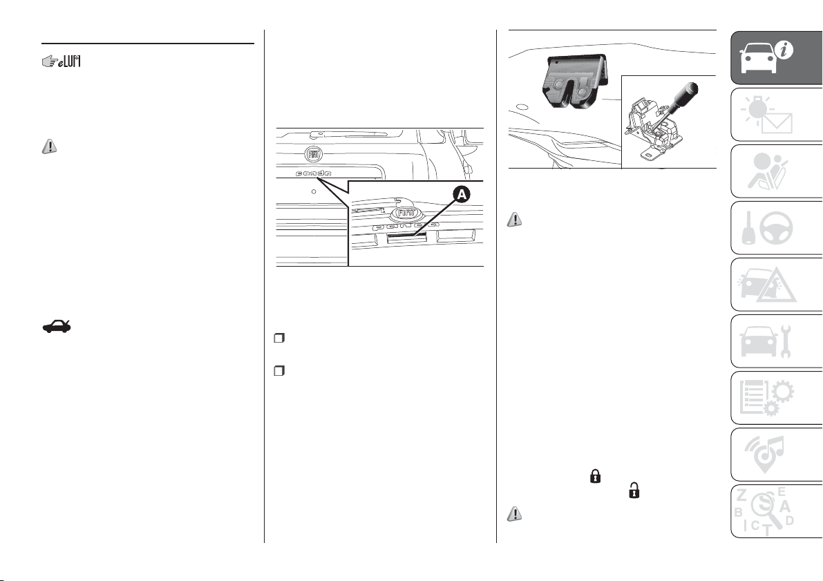
BOOT
The boot unlocking is electrically
operated and is deactivated when the
car is in motion.
OPENING
25)
By mechanical key
On versions with mechanical key, the
luggage compartment can be opened
from outside the vehicle, inserting
the metal insert of the key in the latch
on the tailgate handle and rotating.
With remote control
(for versions/markets, where provided)
The boot is unlocked by pressing the
button on the remote control.
The direction indicators will blink twice.
With electric handle (soft touch)
(for versions/markets, where provided)
For versions with soft touch electrical
handle, the tailgate (when unlocked)
can only be opened from outside the
car using the electric opening handle A
fig. 29 located under the handle until
a click is heard, which indicates
unlocking.
The tailgate can be opened at any time,
if the doors are unlocked. To open it,
enable the handle, opening one of the
front doors or unlocking the doors
with the remote control or using the key
without remote control.
Emergency opening from the inside
Proceed as follows:
remove the rear head restraints and
fully fold the seats;
remove the protective cap and
release the lock using a screwdriver or
the metal insert of the key fig. 30.
CLOSING
26)
Pull the grab handle located inside the
tailgate.
IMPORTANT Before closing the
luggage compartment make sure that
you have the keys, since the luggage
compartment is automatically locked.
LUGGAGE
COMPARTMENT
INITIALISATION
IMPORTANT If the battery is
disconnected or the protection fuse
blows, the boot opening/closing
mechanism must be reinitialised as
follows: close all the doors and the
boot, press the
button on the remote
control, then press the
button.
27) 28) 29)
29
F1D0032
30
F1D0033
27
WARNING
25) Be careful not to hit objects on the
storage shelf when you open the tailgate.
26) With the engine on, always make
sure that the tailgate is closed: exhaust
gases could be drawn inside the load
compartment.
27) Every attachment has a maximum load
capacity of 100 kg.
28) A heavy load that has not been
secured may cause serious injuries to
passengers in the event of an accident.
29) If you are travelling in an area with
limited opportunities for vehicle refuelling
and you wish to bring petrol with you in
a petrol can, you must do so in compliance
with current regulations and using an
approved can, appropriately secured to the
load securing attachments. Anyway, by
doing so, you increase the risk of fire in the
event of an accident with your vehicle.
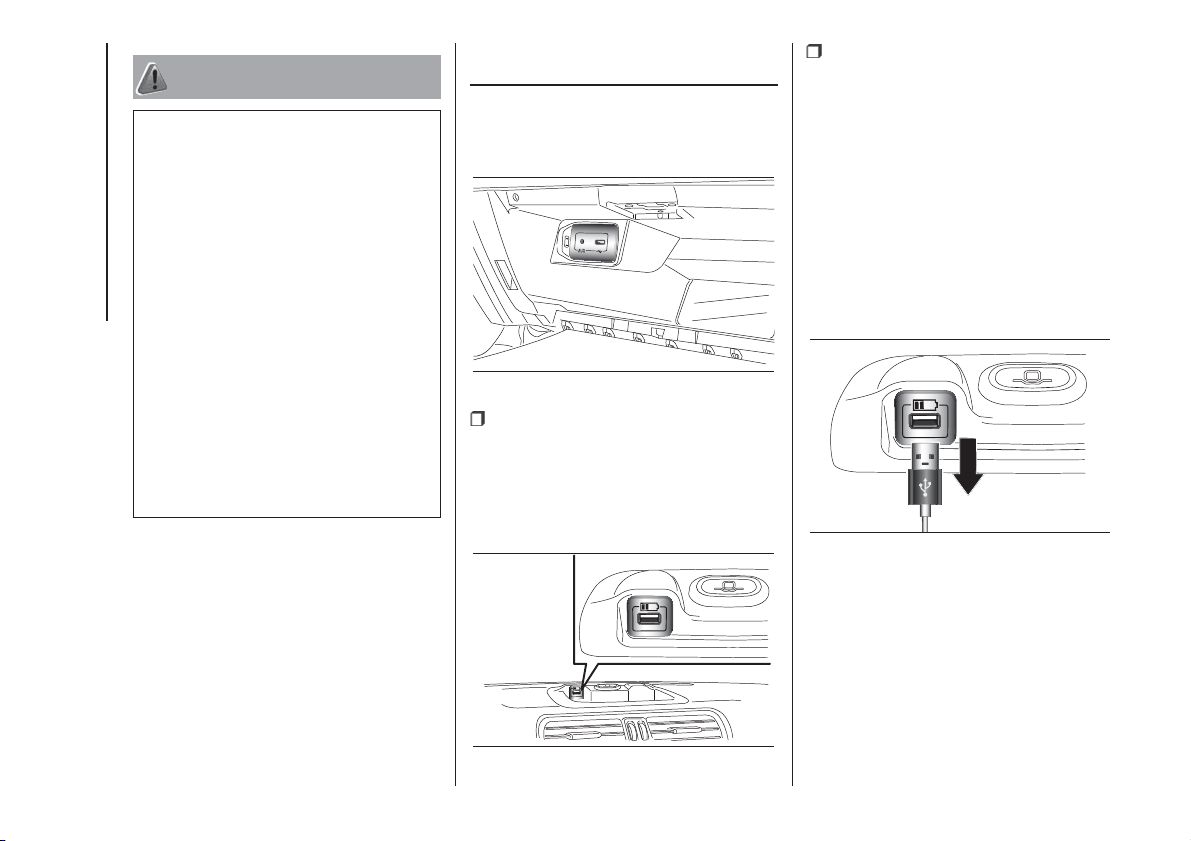
USB PORTS AND
AUX INPUT
(for versions/markets, where provided)
Depending on the trim level, the vehicle
may be equipped with:
a USB port/main AUX input fig. 31.
The AUX input for connecting external
devices (iPod, music player etc.) and
the USB port for transferring data from
USB Pen Drive or other (smartphone
etc.) and slow recharging;
an accessory USB port on the
dashboard fig. 32 with the sole function
of recharging external devices
(smartphone etc.).
IMPORTANT After using a USB
recharging socket, we recommend
disconnecting the device (smartphone),
always removing the cable from the
vehicle socket first, never from the
device. See fig. 33 for example. Cables
left flying or connected incorrectly
could compromise correct recharging
and/or the USB socket condition.
31
F1D0698
32
F1D0697
33
F1D0801
28
KNOWING YOUR CAR
SMARTPHONE
DOCKING
(for versions/markets, where provided)
Depending on the trim level, the car
may be equipped with a smartphone
docking station to be installed on the
dashboard.
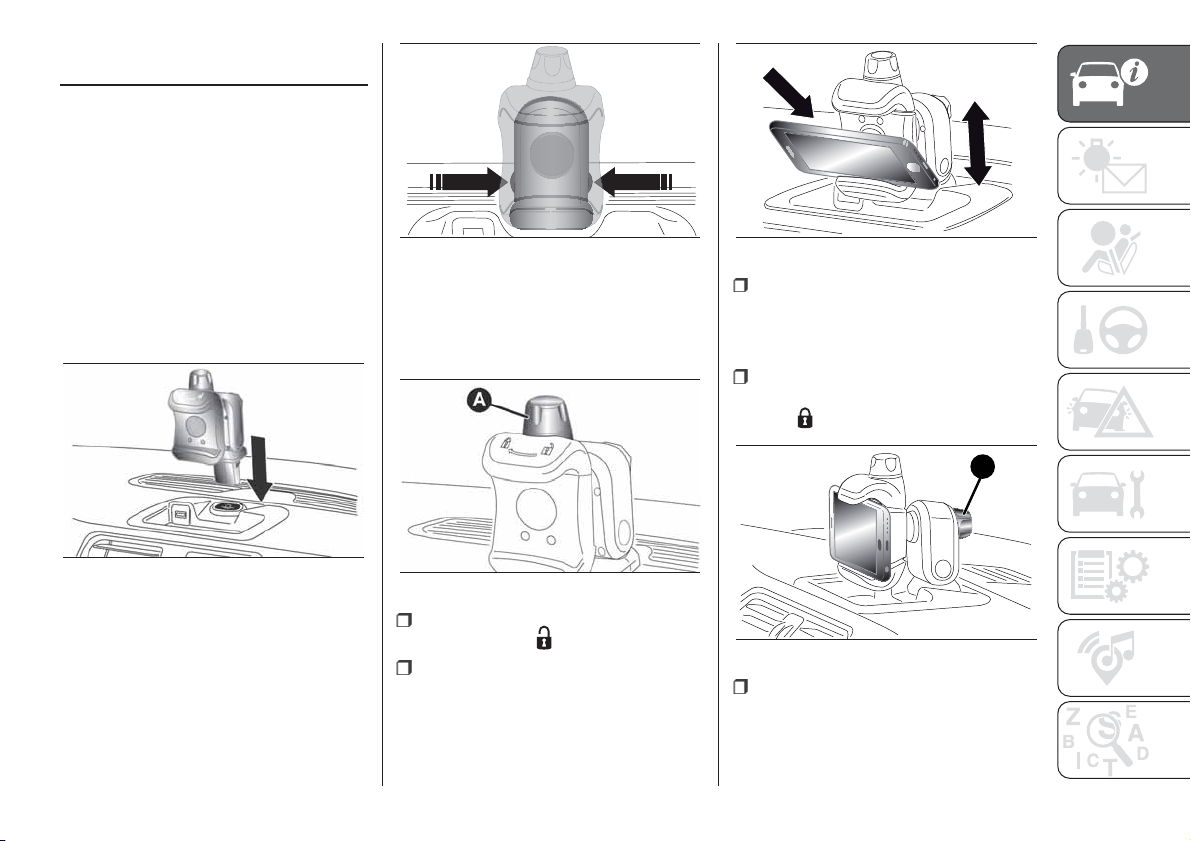
Installing/uninstalling
the station
Install the smartphone docking station
by inserting it in the specific seat on the
dashboard, illustrated in fig. 34 (click
fit).
To remove the docking station, press
both side buttons fig. 35simultaneously.
NOTE When the smartphone docking
station is not in use, it is recommended
to remove it from its seat to avoid
noise and/or vibrations.
Inserting/removing the
smartphone
To insert the smartphone in the docking
station:
ensure that the ring nut A fig. 36 is
turned to position
;
insert the smartphone horizontally in
its seat, placing it on the base of the
docking station, and press to open the
gripping hand fig. 37;
lay the smartphone on the front
base and release it. The load on the
spring inside the docking station will
allow the gripping hand to close;
block the smartphone by turning the
ring A fig. 36 so that it clicks into
position
.
The rear knob B fig. 38 allows
possible adjustments depending on the
weight and geometry of the
smartphone.
34
F1D0702
35
F1D0700
36
F1D0703
37
F1D0699
B
38
F1D0701
29
To remove the smartphone from the
docking station:
turn the ring nut A fig. 36 so that it
clicks into position
;
take out the smartphone by pressing
it down to open the gripping hand;
remove the smartphone from the
docking station and release it. The load
on the spring inside the docking station
will allow the gripping hand to close
after the phone has been removed.
7) 8) 9)
WARNING
7) When the vehicle is moving, the
smartphone must be used in the docking
station only in a horizontal position and
without any inclination (see fig. 37). Any
other position of the docking station is
allowed only with the vehicle stopped, with
the sole purpose of facilitating the insertion
of the smartphone in the station.
8) The maximum dimensions of the usable
smartphones are: 67 mm (width) and 11
mm (depth).
9) The maximum weight of smartphone
that can be installed is 180 g.
VERSION WITH LPG
SYSTEM
30) 31) 14)
10) 11) 12) 13)
INTRODUCTION
The LPG version features two fuel
supply systems: one for petrol and one
for LPG.
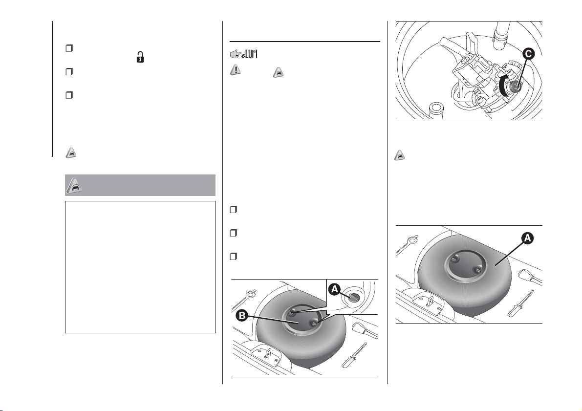
Although the LPG system has
numerous safety features, it is advisable
to proceed as follows every time the
vehicle is not in use for a long period or
moved in an emergency as a result of
a breakdown or accident:
unscrew the fixing devices A fig. 39,
then remove the cover B;
close the LPG cock by turning the
ring nut C fig. 40 clockwise;
refit the cover and retighten the
fastening devices.
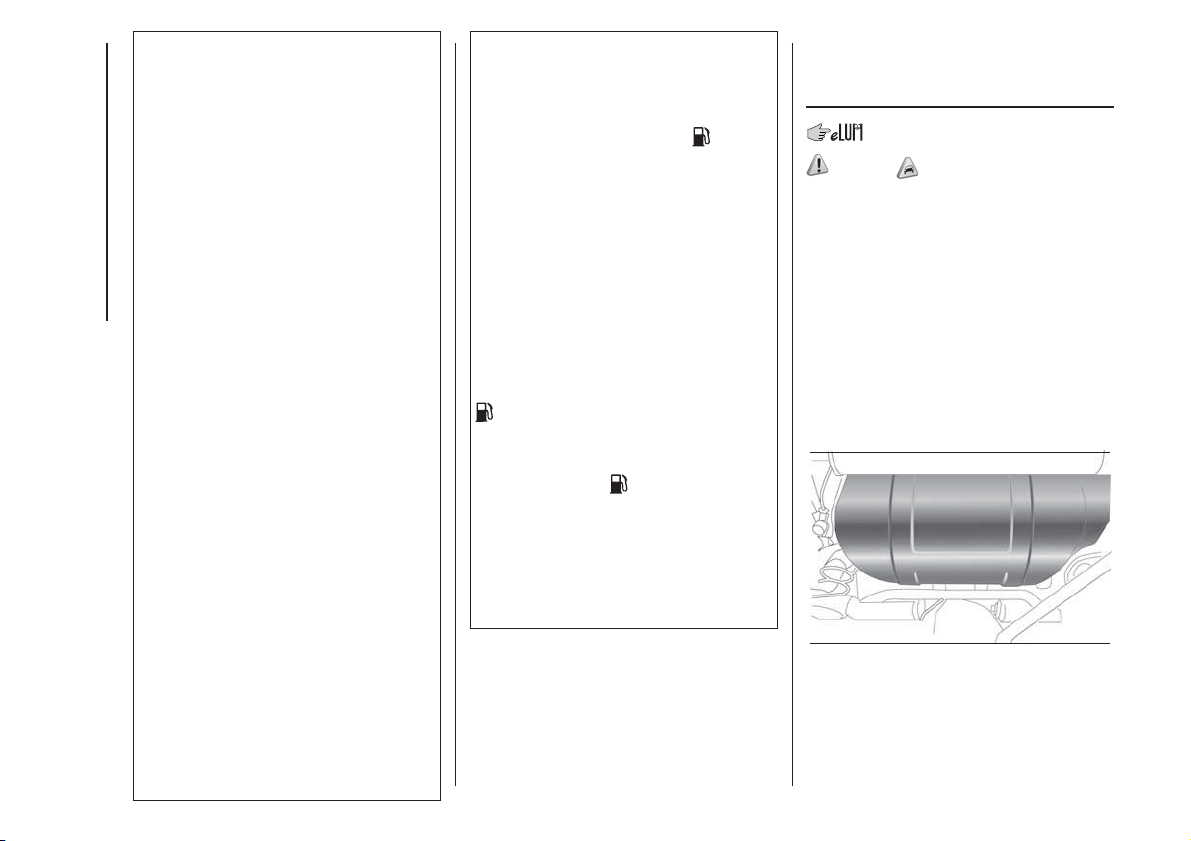
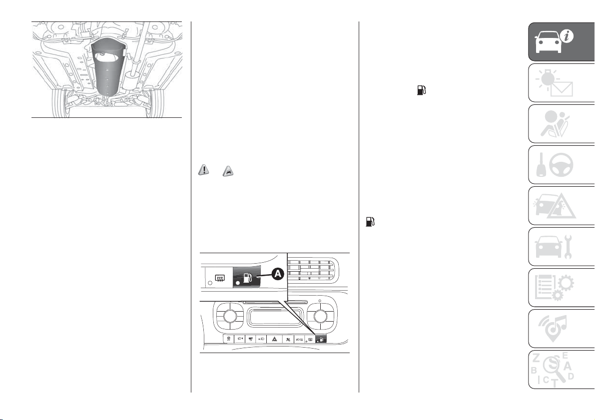
LPG TANK
14)
The car has a (pressurised) tank A fig.
41 for storing LPG in a liquid state.
It is toroidal and is located in the spare
wheel compartment with suitable
protection.
39
F1D0111
40
F1D0112
41
F1D0113
30
KNOWING YOUR CAR
LPG tank certification
The LPG tank is certified in accordance
with the regulations in force.
In Italy, the tank has a life of 10 years
starting from the car registration date. If
the vehicle has been registered in a
country other than Italy, the duration
and the testing/inspection procedures
of the LPG tank can vary depending on
the national laws of that country. In all
case, when the time limit for your
country has expired, go to a Fiat Dealer
to have the tank replaced.
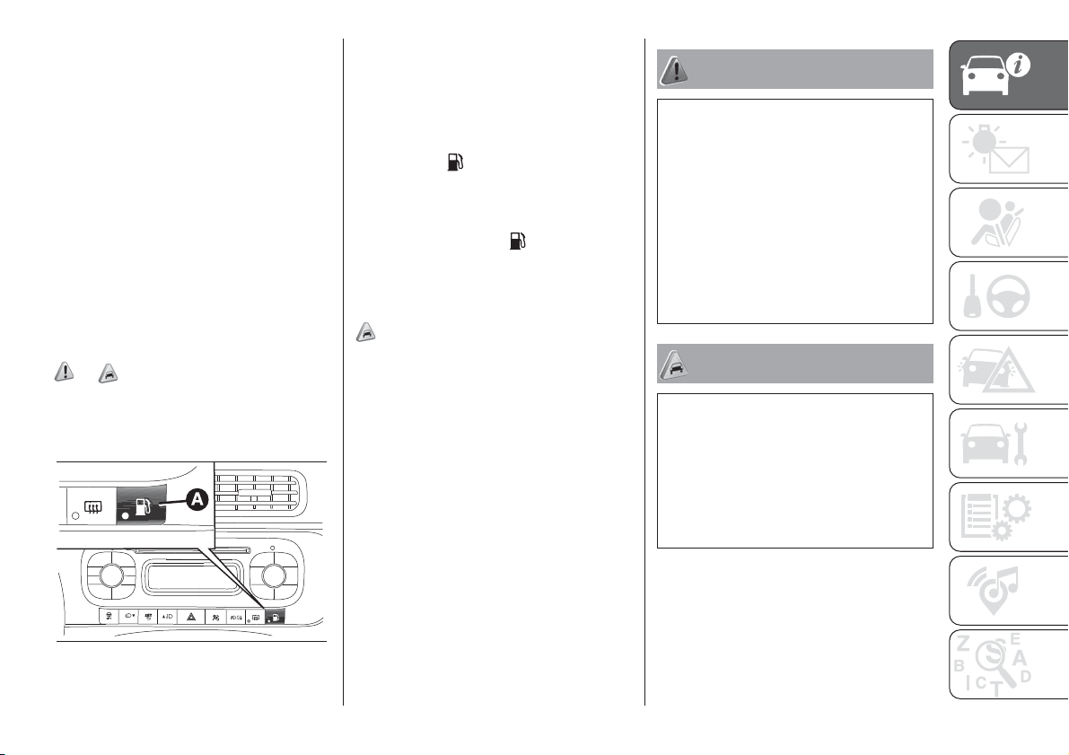
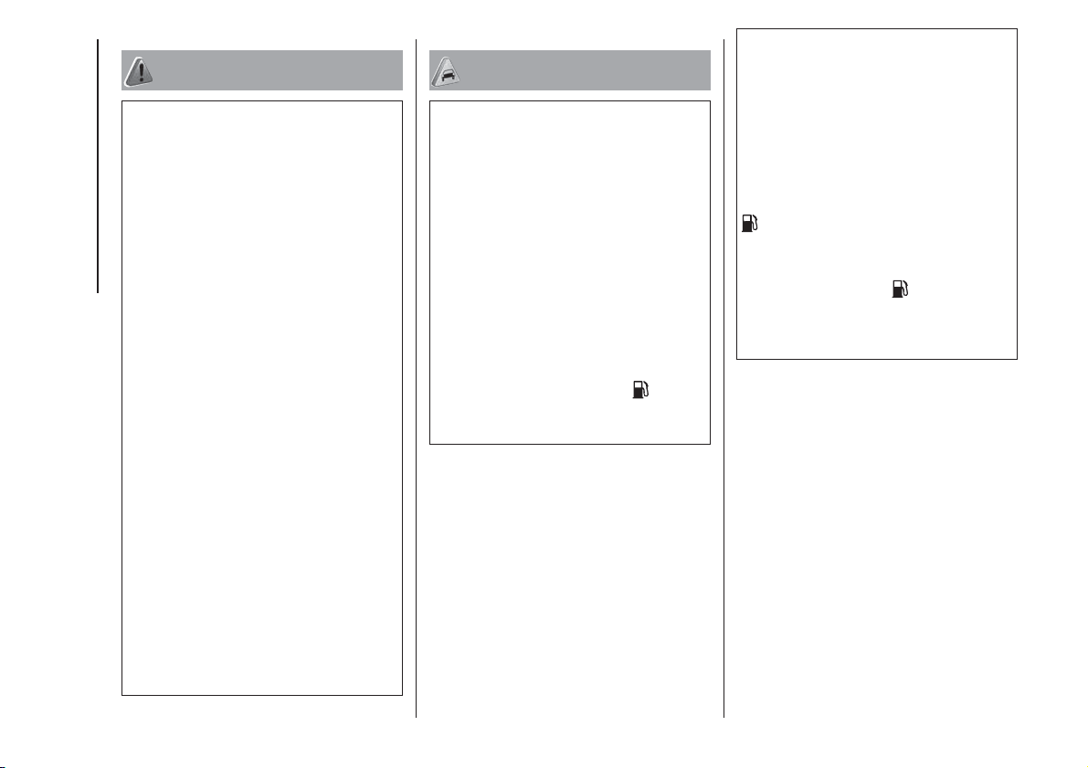
SELECTION OF
PETROL/LPG SUPPLY
TYPE
32) 15) 16) 17)
The button A fig. 42 (petrol/LPG switch)
allows you to select running on petrol
or LPG.
To guarantee switching in full safety, the
actual change to the chosen fuel
system takes place depending on the
car usage conditions; it may not
therefore be immediate.
Switching is confirmed by the green
warning light
on the instrument panel
turning on/off.
If the LPG runs out, switching to petrol
takes place automatically. In this case
the display shows the
icon just
above the wording LPG and the four
bars of the digital gauge turn off.
REFUELLING
18) 19)
LPG
Maximum refuelling capacity (including
reserve): 30.5 litres. The figure already
takes into account the 80% tank filling
limit and the residual fluid required
for priming; this figure represents the
maximum permitted capacity. In
addition, this figure may vary from one
refuelling to another due to differences
between the network pump supply
pressures, pumps having different
supply/locking features, tank not
completely run out of fuel.
WARNING
30) Note that in some countries (including
Italy) there are legal restrictions in force
for parking/garaging motor vehicles fuelled
by gas that is denser than air; LPG comes
under this category.
31) Modifications or repairs to the supply
system that are not carried out correctly or
do not take the system technical
specifications into account can cause
malfunctions leading to the risk of fire.
32) Do not switch between the two
operating modes whilst starting the engine.
WARNING
10) The system operates at temperatures
ranging between -20°C and 100°C.
11) If the fuel runs out while running on
LPG, the car switches to petrol
automatically and all the bars of the digital
indicator on the display turn off. The
display remains in this state until the next
LPG refuelling.
42
F1D0109
31
12) The car is equipped with a gaseous
LPG injection system designed specifically
for it: it is therefore absolutely forbidden
to alter the configuration of the system or
its components. The use of other
components or materials could cause
malfunctions and lead to a reduction in
safety; therefore, in the case of problems,
contact a Fiat Dealership. To prevent
damage to the gas system parts when
towing or raising the vehicle, follow the
instructions in the "Towing the vehicle"
paragraph of the Owner Handbook.
13) When painting in an oven, the LPG
tank must be removed from the car and
later refitted by a Fiat Dealership. Although
the LPG system has numerous safety
features, it is advisable to proceed
as follows every time the vehicle is not in
use for a long period or moved in an
emergency as a result of a breakdown or
accident: unscrew the fastening devices A
fig. 39, then remove the cover B. Close
the LPG cock rotating the ring nut C
clockwise fig. 41. Refit the cover and
retighten the fastening devices.
14) Periodically (at least once every six
months), it is advisable to let the LPG in the
tank run out and, at the next refuelling,
check that it does not exceed the
maximum capacity of 30.5 litres (reserve
included) (with a tolerance of 2 litres
excess) (see instructions in the "Capacities"
paragraph of this Supplement). If the level
is above 30.5 litres (reserve included)
contact a Fiat Dealership immediately.
15) Regardless of the last fuel system
used, at the following engine starting, after
the initial petrol stage, the system will
automatically switch to LPG.
16) When switching from petrol to LPG is
requested, a metal noise from the valves
which pressurise the circuit can be heard.
As a result of the switching logic described
above, a delay between the valve ticking
and the the green warning light
on
the instrument panel turning off is
completely normal.
17) In particular usage conditions, such as
starting and operation at low ambient
temperature or LPG supply with low
propane content, the system may switch
temporarily to petrol operation, without
indicating the performed switching. In the
event of low LPG levels in the tank or
request for high performance (e.g.
overtaking, fully laden vehicle, steep hills)
the system may automatically switch to
petrol operation to guarantee the engine
power requested. The green warning light
on the instrument panel turns on to
indicate this. When the above conditions
are no longer present, the system
automatically restores LPG operation; the
green warning light
switches off. To
achieve the automatic switching described
above, make sure that there is always
enough fuel in the petrol tank.
18) Only use LPG for motor vehicles.
19) It is strictly forbidden to use any
additive in the LPG.
VERSION WITH
METHANE SYSTEM
(Natural Power)
33) 34) 35) 20)
INTRODUCTION
The "Natural Power" version features
two fuel systems, one for petrol and
one for natural gas (methane).
METHANE CYLINDERS
The vehicle is equipped with two
cylinders (total capacity about 72 litres)
fig. 43 - fig. 44 located under the
vehicle’s floor and protected by two
special guards.
43
F1D0137
32
KNOWING YOUR CAR
The methane, stored in the cylinders at
high pressure, flows through a
dedicated pipe to reach the pressure
regulator/reduction unit which supplies
the two methane injectors at low
pressure (about 9 bar).
Cylinder certification
The methane cylinders are certified in
accordance with ECE Regulation no.
110.
The cylinders must be inspected, in
accordance with ECE Regulation
Procedure no. 110, every 4 years from
the car registration date or in
accordance with specific regulations in
individual countries.
The plates provided by the Dealership
with the on board documentation
contain the date for the first inspection
of the cylinders. Methane refuelling
stations are not authorised to refill the
cylinders when the inspection date has
expired.
IMPORTANT If the vehicle has been
registered in a country other than Italy,
the certification data, identification
and inspection procedures for
the methane cylinders should conform
to the legislation in that country. In
any case, remember that the life of the
cylinders is 20 years from the
production date as set out in ECE
Regulation no. 110.
SELECTION OF
PETROL/METHANE
SUPPLY TYPE
36) 21) 22) 23)
This engine normally runs on methane
except during starting, when it runs
on petrol.
The button A fig. 45 (petrol/methane
switch) allows you to select running on
petrol or methane.
To guarantee switching in full safety, the
actual change to the chosen fuel
system takes place depending on the
car usage conditions; it may not
therefore be immediate.
Switching is confirmed by the green
warning light
on the instrument panel
turning on/off.
In addition, when starting at outside
temperatures below approximately
–10°C, the switching times from petrol
to methane increase to allow the
pressure regulator/reduction unit to
heat up.
If the methane has run out, switching to
petrol takes place automatically. In this
case, the four bars of the digital gauge
turns off and the green warning light
on the instrument panel turns on.
REFUELLING
Methane
Capacity: about 12 kg. The total
volume of cylinders is about 72 litres.
44
F1D0138
45
F1D0109
33
WARNING
33) The Fiat Panda Natural Power is
equipped with a high pressure methane
fuel supply system, designed to operate at
a rated pressure of 200 bar. It is dangerous
to stretch the system with higher
pressures. To prevent damage to the gas
system parts when towing or lifting the
vehicle, follow the instructions in the Owner
Handbook, in the paragraph: “Towing the
vehicle”. If there is a fault in the methane
system, only contact a Fiat Dealership. Do
not alter the methane system configuration
or components. They are designed
exclusively for the Fiat Panda Natural
Power. The use of other components or
materials could cause malfunctions and
prejudice safety.
34) When oven painting, the cylinders must
be removed from the vehicle and
subsequently refitted by a Fiat Dealership.
Although the methane system has
numerous safety features, it is advisable to
close the manual cocks for the cylinders
every time the vehicle is not in use for
a long period, transported on other
vehicles or moved in an emergency as a
result of a breakdown or accident.
35) Modifications or repairs to the supply
system that are not carried out correctly or
do not take the system technical
specifications into account can cause
malfunctions leading to the risk of fire.
36) Do not switch between the two
operating modes whilst starting the engine.
WARNING
20) If the fuel runs out while running on
methane, the car switches to petrol
automatically and all the bars of the digital
indicator on the display turn off. The
display remains in this state until the next
methane refuelling.
21) Regardless of the last fuel system
used, at the following engine starting, after
the initial petrol stage, the system will
automatically switch to methane.
22) When switching from petrol to methane
is requested, a metal noise from the valves
which pressurise the circuit can be heard,
as it happens while starting the car. As a
result of the switching logic described
above, a delay between the valve ticking
and the the green warning light
on
the instrument panel turning off is
completely normal.
23) In particular usage conditions, such as
starting and operation at low ambient
temperature, the system may switch
temporarily to petrol operation, without
indicating the performed switching. In the
event of low methane levels in the tank or a
request for high performance (e.g.
overtaking, fully laden vehicle, steep hills)
the system may automatically switch to
petrol operation to guarantee the engine
power requested. The green warning light
on the instrument panel turns on to
indicate this. When the above conditions
are no longer present, the system
automatically restores methane operation.
The green warning light
turns off. To
achieve the automatic switching described
above, make sure that there is always
enough fuel in the petrol tank.
34
KNOWING YOUR CAR
KNOWING THE INSTRUMENT PANEL
This section of the handbook gives you
all the information you need to
understand, interpret and use the
instrument panel correctly.
CONTROL PANEL AND
ON-BOARD INSTRUMENTS ........... 36
DISPLAY ......................................... 37
WARNING LIGHTS AND
MESSAGES .................................... 39
- Red warning lights ............................ 39
- Amber warning lights......................... 45
- Green warning lights ......................... 53
- Blue warning lights ............................ 54
-Symbols and messages on the
display................................................. 54
35
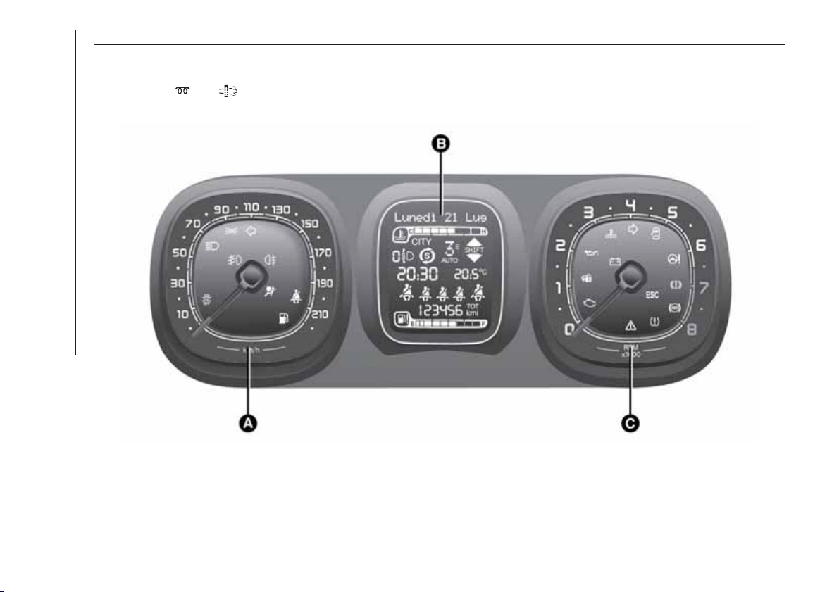
CONTROL PANEL AND ON-BOARD INSTRUMENTS
.
The instrument background colour and type may vary according to the versions.
The warning lights on the instrument panel may change according to the version/trim level (e.g. LPG, Cross etc.) of the vehicle.
Warning lights
and are available on diesel versions only. On diesel versions, the maximum engine speed (red range on
the rev counter) corresponds to 6000 rpm.
A. Speedometer (speed indicator) – B. Multifunction display – C. Rev counter
46
F1D0690
36
KNOWING THE INSTRUMENT PANEL
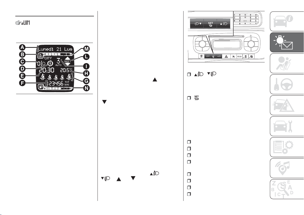
DISPLAY
The display fig. 47 will show the
following information:
A
Date
B
Dualdrive electric power steering
engagement indication (CITY text)
C
Headlight alignment position (only
with dipped beam headlights on)
D
Start&Stop function indication (for
versions/markets where provided)
E
Time
F
Odometer (display of distance
travelled in kilometres/miles)
G
Seat belt indicators
H
Outside temperature (for versions/
markets, where provided)
I
Gear engaged indication (Dualogic
versions only)
L
Gear Shift Indicator (for versions/
markets, where provided)
M
Engine coolant temperature indicator.
N
Fuel level indicator.
GEAR SHIFT INDICATOR
The GSI (Gear Shift Indicator) system
advises the driver to change gear
through a specific indication on the
control panel. Through the GSI, the
driver is notified that changing gear will
allow a reduction in fuel consumption.
When the SHIFT UP icon (
SHIFT)
is shown on the display, the GSI
advises the driver to engage a higher
gear, while when the SHIFT DOWN icon
(
SHIFT) is shown, the GSI advises
the driver to engage a lower gear.
The indication remains displayed until a
gear is shifted or the driving conditions
go back to a situation where
gearshifting is not required to improve
consumption.
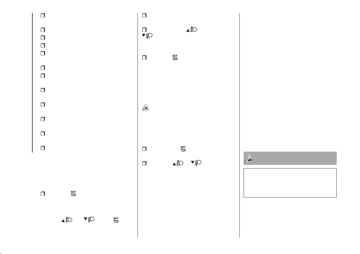
CONTROL BUTTONS
They are located on the dashboard fig.
48.
NOTE The symbol on the buttons
depends on the version:
and
or and .
/ : press and release the
buttons to scroll the menu items
upwards or downwards, or to
increase/decrease the displayed value.
: press briefly to access the
menu and/or go to next screen
or confirm the desired selection. Hold
pressed to go back to the standard
screen.
SETUP MENU
The menu includes the following items:
MENU
DIMMER
SPEED BUZZER
HEADLAMP SENSOR (for
versions/markets where provided)
TRIP B ACTIVATION/DATA
SET TIME
SET DATE
RADIO REPETITION (for markets/
versions, where provided)
47
F1D0002
48
F1D0003
37
AUTOCLOSE (for versions/markets,
where provided)
MEASUREMENT UNIT
LANGUAGE
BUZZER VOLUME
SEAT BELT BUZZER (for versions/
markets, where provided)
SERVICE
AIRBAG/PASSENGER BAG (for
versions/markets, where provided)
DAYTIME LIGHTS (for
versions/markets, where provided)
RESET TYRE (for versions/markets,
where provided)
CITY BRAKE C. (for versions/
markets, where provided)
OIL LEVEL RESET (for versions/
markets, where provided)
EXIT MENU
Deactivating the passenger front
airbag and side bag
This function is used to activate/
deactivate the front passenger airbag.
Proceed as follows:
press the button and, after the
display shows the message "Passenger
Bag: Off to deactivate) or the message
("Passenger Bag: On" to activate) by
pressing
and , press once
again;
a confirmation request message will
appear on the display;
by pressing the or
buttons, select "Yes" (to confirm
activation/deactivation) or "No" (to
cancel);
press the button briefly; a
message confirming the selection is
displayed and you return to the menu
screen. Hold down the button to return
to the standard screen without storing.
Oil level reset
(for versions/markets, where provided)
24)
This function resets the oil top-up
warning that occurs approximately
every 8,000 km.
Proceed as follows to reset this warning
after topping up the oil:
Press button briefly. The display
will ask you to confirm the reset.
Press the or button and
select “YES” to reset the warning or
“NO” to cancel the operation.
TRIP COMPUTER
The Trip computer is used to display
information on car operation when the
key is turned to MAR. Two separate
trips, called “Trip A” and “Trip B”, are
provided to monitor the entire mission
(journey) in a reciprocally independent
manner.
“Trip A” can be used to display the
values relating to: "Outside temperature
(for versions/markets, where provided)",
"Range", "Travel Distance", "Average
Fuel consumption", "Current fuel
consumption", "Average speed", "Travel
time (driving time)"
“Trip B” may be used to display the
figures relating to: "Travel Distance B",
"Average fuel consumption B",
"Average speed B", "Travel time B
(driving time)". The “Trip B” function
may be excluded.
Both functions can be reset (reset
means start of a new journey).
To reset, hold the TRIP button on the
right steering wheel stalk pressed.
NOTE “Range” and “Current fuel
consumption" parameters cannot be
reset.
WARNING
24) Failure to top up the engine oil could
result in a low level, which could prevent
normal car operation and even cause it to
stop
38
KNOWING THE INSTRUMENT PANEL
WARNING LIGHTS AND MESSAGES
IMPORTANT NOTES
IMPORTANT Warning lights are accompanied by a specific message and/or sound when applicable. These indications are
indicative and precautionary and as such must not be considered as exhaustive and/or alternative to the information contained
in the Owner Handbook, which you are advised to read carefully in all cases. In the event of a failure indication, always refer
to the contents of this chapter.
IMPORTANT Failure indications displayed are divided into two categories: very serious and less serious failures. Serious faults
are indicated by a repeated and prolonged warning "cycle". Less serious faults are indicated by a warning "cycle" with a shorter
duration. The display cycle of both categories can be interrupted by pressing the
button. The instrument panel warning
light will stay on until the cause of the malfunction is eliminated.
WARNING LIGHTS ON INSTRUMENT PANEL
Red warning lights
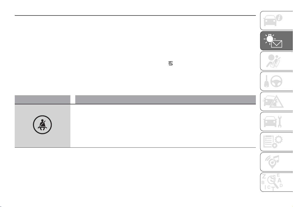
Warning light What it means
SEAT BELTS REMINDER
(for versions/markets, where provided)
The warning light switches on constantly with the vehicle stationary and the driver's side or passenger side
seat belt (when the passenger is present) not fastened. The warning light will flash and a buzzer will sound
if the vehicle is in motion and the front seat belts are not correctly fastened.
For permanent deactivation of the acoustic signal (buzzer) of the S.B.R. (Seat Belt Reminder) system
contact a Fiat Dealership. The system can be reactivated using the Setup Menu.
39
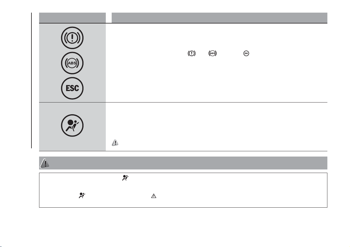
Warning light What it means
EBD FAILURE
The simultaneous switching on of the (red), (amber) and (amber) warning lights with the engine
on indicates either an anomaly of the EBD system or that the system is not available. In this case, the rear
wheels may suddenly lock and the vehicle may swerve when braking hard. On certain versions a dedicated
message is displayed.
Drive very carefully to the nearest Fiat Dealership to have the system inspected immediately.
AIRBAG FAILURE
When the ignition key is turned to MAR, the warning light switches on but should switch off after a few
seconds.
If the warning light turns on continuously, it indicates a fault in the airbag system. On certain versions a
dedicated message is displayed.
37) 38)
WARNING
37) If, when turning the key to MAR, the warning light does not turn on or if it stays on while driving, there could be a fault in the restraint
systems; in this case, the airbags or pretensioners may not be deployed in the event of impact or, in a few cases, they may deploy
accidentally. Contact a Fiat Dealership immediately to have the system checked.
38) A failure of the
warning light is indicated by the warning light flashing. In this case, any faults of the airbag system might be not
signalled. Before continuing, contact a Fiat Dealership immediately to have the system checked.
40
KNOWING THE INSTRUMENT PANEL
Warning light What it means
LOW BRAKE FLUID/HANDBRAKE ENGAGED
When the ignition key is turned to MAR, the warning light switches on but should switch off after a few
seconds.
Low brake fluid level
The warning light turns on when the level of the brake fluid in the reservoir falls below the minimum level,
possibly due to a leak in the circuit. On certain versions a dedicated message is displayed.
39)
Handbrake engaged
The warning light switches on when the handbrake is engaged. If the vehicle is moving a buzzer will also
sound.
IMPORTANT If the warning light turns on when travelling, check that the handbrake is not engaged.
LOW BATTERY CHARGE
(for versions/markets, where provided)
When the ignition key is turned to the MAR position, the warning light comes on, but it should go off as
soon as the engine is started (if the engine is idling, there may be a short delay before it goes off).
If the warning light stays on constantly or flashing, on some versions along with a dedicated message on
the display, contact a Fiat Dealership.
DOORS/BONNET/LUGGAGE COMPARTMENT OPEN
The warning light comes on, together with a dedicated message on the display on some versions, when
one or more doors, the bonnet or the tailgate are not properly closed. An acoustic signal is activated with
the doors open and the car moving.
WARNING
39) If the warning light switches on when travelling, stop the car immediately and contact a Fiat Dealership.
41
Warning light What it means
INSUFFICIENT ENGINE OIL/PRESSURE
When the ignition key is turned to the MAR position, the warning light comes on, but it should go off as
soon as the engine is started.
Insufficient engine oil pressure
The warning light turns on constantly, on some versions along with a dedicated message on the display,
when the system detects that engine oil pressure is insufficient.
40)
WARNING
40) If the warning light switches on when travelling (on certain versions together with the message on the display), stop the engine
immediately and contact a Fiat Dealership.
42
KNOWING THE INSTRUMENT PANEL
Warning light What it means
Engine oil degraded
(diesel versions with DPF)
The warning light comes on flashing, on some versions along with a dedicated message on the display.
The warning light flashes for 3 minute cycles with the warning light off for intervals of 5 seconds until oil is
changed.
After the initial warning, each time the engine is started up, the warning light will continue to flash in the
same mode, until the oil is changed. On certain versions a dedicated message is displayed.
The flashing warning light should not be considered a fault, it simply informs the customer that the oil
needs to be changed following normal car use.
Remember that the deterioration of the engine oil is accelerated by:
mainly town use of the vehicle which makes the DPF regeneration process more frequent;
use of the vehicle for short drives, in which the engine does not have time to reach its regular operating
temperature;
repeated interruptions to the regeneration process signalled by the DPF warning light coming on.
41)
WARNING
41) If the warning light switches on, the degraded engine oil must be changed as soon as possible, and never more than 500 km from the
first time that the warning light switches on. Failure to observe the above may result in severe damage to the engine and invalidate the
warranty. Remember that the operation of this warning light is not related to the amount of oil in the engine. Therefore, never top up with oil
when the light starts flashing.
43
Warning light What it means
ENGINE COOLANT TEMPERATURE TOO HIGH
The warning light switches on when the ignition key is turned to MAR, but it should switch off after a few
seconds.
The warning light comes on, on some versions along with a message on the display, when the engine is
overheated.
In normal driving conditions: stop the car, switch off the engine and check that the water level in the
reservoir is not below the MIN mark. In this case, wait for the engine to cool down, then slowly and
carefully open the cap, top up with coolant and check that the level is between the MIN and MAX marks on
the reservoir itself. Also check visually for any fluid leaks. If, when restarting, the warning light switches on
again, contact a Fiat Dealership.
If the car is used under demanding conditions (e.g. towing trailers uphill or fully loaded): slow down
and, if the warning light stays on, stop the car. Wait for 2 or 3 minutes with the engine running and slightly
accelerated to further favour the coolant circulation. Then stop the engine. Check that the coolant level is
correct as described above.
IMPORTANT Over demanding routes, it is advisable to keep the engine on and slightly accelerated for a
few minutes before switching it off.
“DUALDRIVE” ELECTRIC POWER STEERING FAILURE
When the key is turned to MAR, the warning light switches on but it should switch off after a few seconds.
If the warning light stays on, on some versions along with a dedicated message on the display, you may
not have steering assistance and the effort required to operate the steering wheel could be notably
increased; steering is, however, possible.
In this case, contact a Fiat Dealership.
IMPORTANT In some circumstances, factors independent of the electric power steering could cause the
warning light on the instrument panel to switch on. In this case, stop the car immediately (should it be in
motion), stop the engine for about 20 seconds and then restart the engine. If the warning light, on some
versions along with a dedicated message on the display, remains on, contact a Fiat Dealership.
IMPORTANT After the battery is disconnected, the steering must be initialised. The warning light switches
on to indicate this. To carry out this procedure, simply turn the steering wheel all the way from one end to
the other or drive in a straight line for about a hundred metres.
44
KNOWING THE INSTRUMENT PANEL
Warning light What it means
"DUALOGIC" GEARBOX FAILURE
When the ignition key is turned to MAR, the warning light switches on but should switch off after a few
seconds.
The warning light comes on flashing, along with a dedicated message on the display and an acoustic
warning, to indicate transmission failure.
25)
WARNING
25) If the gearbox is faulty, contact a Fiat Dealership as soon as possible to have the system checked.
Amber warning lights
Warning light What it means
ABS FAILURE
The warning light switches on when the ignition key is turned to MAR, but it should switch off after a few
seconds.
The warning light comes on, on some versions along with a message on the display, when the system is
inefficient. In this case the braking system maintains its efficiency unaltered but without the advantage of
the ABS system.
Drive carefully and contact a Fiat Dealership as soon as possible.
PASSENGER AIRBAG/SIDE BAGS DEACTIVATED
The warning light is located on the dashboard in central position and switches on deactivating the front
passenger airbag and the side bag. With front passenger airbag on, when the ignition key is turned to
MAR, the warning light switches on constantly for several seconds and then it should switch off.
42)
45
WARNING
42) A failure of the warning light is indicated by the warning light switching on. In addition, the airbag system automatically disables the
airbags on the passenger's side (front and side bags where provided). Before continuing, contact a Fiat Dealership immediately to have the
system checked.
Warning light What it means
CITY BRAKE CONTROL SYSTEM DEACTIVATED
(for versions/markets, where provided)
The warning light switches on when the City Brake Control system is deactivated through the Setup Menu.
INJECTION/EOBD SYSTEM FAILURE
In normal conditions, when the ignition key is turned to MAR the warning light switches on, but it should
switch off as soon as the engine is started.
If the warning light remains on or switches on whilst driving, the injection system is not working properly; in
particular, if the warning light switches on steadily, this indicates a malfunction in the supply/ignition system
that could cause excessive exhaust emissions, a possible loss of performance, poor driveability and high
fuel consumption.
Under these conditions, the vehicle can continue travelling at moderate speed without demanding
excessive effort from the engine. Prolonged use of the vehicle with the warning light on constantly may
cause damage: contact a Fiat Dealership as soon as possible.
The warning light switches off if the malfunction disappears, but is still stored by the system.
NOTE For petrol engines, if the warning light flashes, the catalytic converter may be damaged. In this case,
it is necessary to release the accelerator pedal to lower the speed of the engine until the warning light
stops flashing; continue the journey at moderate speed, trying to avoid driving conditions that may cause
further flashing and contact a Fiat Dealership as soon as possible.
26)
46
KNOWING THE INSTRUMENT PANEL
WARNING
26) Go to a Fiat Dealership as soon as possible if warning light either does not light up when the key is turned to MAR or if while
travelling the warning light switches on or flashes (along with a message and a symbol on the display on some versions). The operation of the
warning light may be checked by the traffic police using specific devices. Comply with the laws and regulations of the country where
you are driving.
Warning light What it means
ESC SYSTEM
(for versions/markets, where provided)
The warning light switches on when the ignition key is turned to MAR, but it should switch off after a few
seconds.
If the warning light does not switch off or stays on while driving, on some versions along with a message
on the display, contact a Fiat Dealership. Flashing of the warning light while driving indicates the
intervention of the ESC system.
Hill Holder failure
This warning light switches on, on some versions along with a dedicated message on the display, in the
case of a Hill Holder system fault.
In this case, contact a Fiat Dealership.
ELD system failure
(For versions/markets, where provided)
This warning light switches on, on some versions along with a dedicated message on the display, in the
case of an ELD system failure.
In this case, contact a Fiat Dealership as soon as possible.
FIAT CODE SYSTEM FAILURE
The warning light (or the symbol on the display) switches on, on some versions along with a dedicated
message on the display, to signal the Fiat CODE system failure.
In this case, contact a Fiat Dealership as soon as possible.
47
Warning light What it means
GLOW PLUG HEATING/GLOW PLUG HEATING FAILURE (diesel versions)
Plug preheating
This warning light switches on when the key is turned to MAR. It should switch off as soon as the heater
plugs have reached a preset temperature. The engine can be started as soon as the warning light switches
off.
IMPORTANT At moderate or high ambient temperatures the warning light may stay on for an extremely
short time.
Heater plug preheating failure
The warning light will flash, on some versions along with a dedicated message on the display, to indicate a
fault in the plug preheating system.
Contact a Fiat Dealership as soon as possible to have the fault fixed.
FUEL RESERVE - LIMITED RANGE
This warning light switches on when 5 to 7 litres of fuel are left in the tank. When the remaining range is
lower than approx. 50 km (or equivalent value in miles), on some versions, the display will show a
dedicated message.
IMPORTANT The warning light will flash to indicate a system fault. If this is the case, go to a Fiat Dealership
to have the system checked.
REAR FOG LIGHT
The warning light switches on when the rear fog light is turned on.
48
KNOWING THE INSTRUMENT PANEL

Warning light What it means
DPF (PARTICULATE FILTER) CLEANING IN PROGRESS (Diesel versions with DPF)
When the ignition key is turned to MAR, the warning light switches on but should switch off after a few
seconds.
The warning light switches on constantly, on some versions along with a dedicated message on the
display, to notify the driver that the DPF system needs to eliminate captured pollutants (particulate) through
the regeneration process.
The warning light does not come on every time the DPF is being regenerated, rather only when the driving
conditions are such that the driver needs to know it. To switch the warning light off, the vehicle must be
kept moving until the regeneration process is completed. On average, the process lasts 15 minutes.
Optimal conditions for completing the process are achieved by travelling at 60 km/h with engine speed
above 2000 rpm.
If this light switches on, it does not mean that the vehicle is defective, so there is no need to take it to a
workshop.
43)
WARNING
43) The driving speed must always be suitable for traffic and weather conditions and the driver must always comply with the Highway Code.
The engine can also be switched off if the DPF warning light is on; nevertheless, repeated interruptions of the regeneration process could
cause an early deterioration of engine oil. For this reason, always wait until the warning light switches off before stopping the engine as
described above. Do not complete the DPF regeneration process when the vehicle is stopped.
49
Warning light What it means
GENERAL FAILURE INDICATION
(for versions/markets, where provided)
The warning light turns on in the following circumstances.
Speed limit exceeded
(for versions/markets, where provided)
The warning light switches on when the speed limit set in the Setup Menu is exceeded. When the car
exceeds this value, an acoustic indication is emitted and a dedicated appears on the display on some
versions.
Fuel cut-off system intervention/failure
This warning light switches on, on some versions along with a dedicated message on the display, in the
case of fuel cut-off system activation/failure.
Start&Stop system failure
(for versions/markets, where provided)
The warning light comes on when a fault is detected in the Start&Stop system. In the event of a Start&Stop
system failure, contact a Fiat Dealership.
Temporary or permanent City Brake Control system failure
(for versions/markets, where provided)
The warning light switches on, on some versions along with a message on the display, when a temporary
or permanent City Brake Control system fault is detected. If the fault is permanent: contact a Fiat
Dealership to have the system checked.
Airbag failure
When this warning light starts flashing, for versions/markets where provided, this indicates an airbag
warning light fault. In this case, the airbag may not indicate possible airbag system malfunctions. Contact a
Fiat Dealership immediately.
50
KNOWING THE INSTRUMENT PANEL
Warning light What it means
Parking sensor failure
(for versions/markets, where provided)
The warning light switches on, on some versions along with a dedicated message on the display, when a
fault is detected in the parking sensors.
Exterior lights failure
(for versions/markets, where provided)
The warning light switches on when a fault is detected in one of the following lights: side lights, number
plate lights, rear fog lights, direction indicators, daytime running lights (DRL).
Engine oil pressure sensor failure
(for versions/markets, where provided)
The engine oil pressure sensor failure is indicated by the activation of the warning light on the instrument
panel.
ELD system failure (for versions/markets, where provided)
The warning light switches on, on some versions along with a dedicated message on the display, when a
fault is detected in the 4x4 drive. Contact a Fiat Dealership as soon as possible.
Water in diesel filter (diesel versions)
(for versions/markets, where provided)
The warning light switches on when the ignition key is turned to MAR, but it should switch off after a few
seconds. The warning light switches on when water is detected in the diesel filter. On certain versions a
dedicated message is displayed.
27)
WARNING
27) If the warning light switches on (on some versions together with the dedicated message on the display), contact a Fiat Dealership as
soon as possible to have the system bled. If the warning appears immediately after refuelling, water may have entered the tank: turn the
engine off immediately and contact a Fiat Dealership.
51
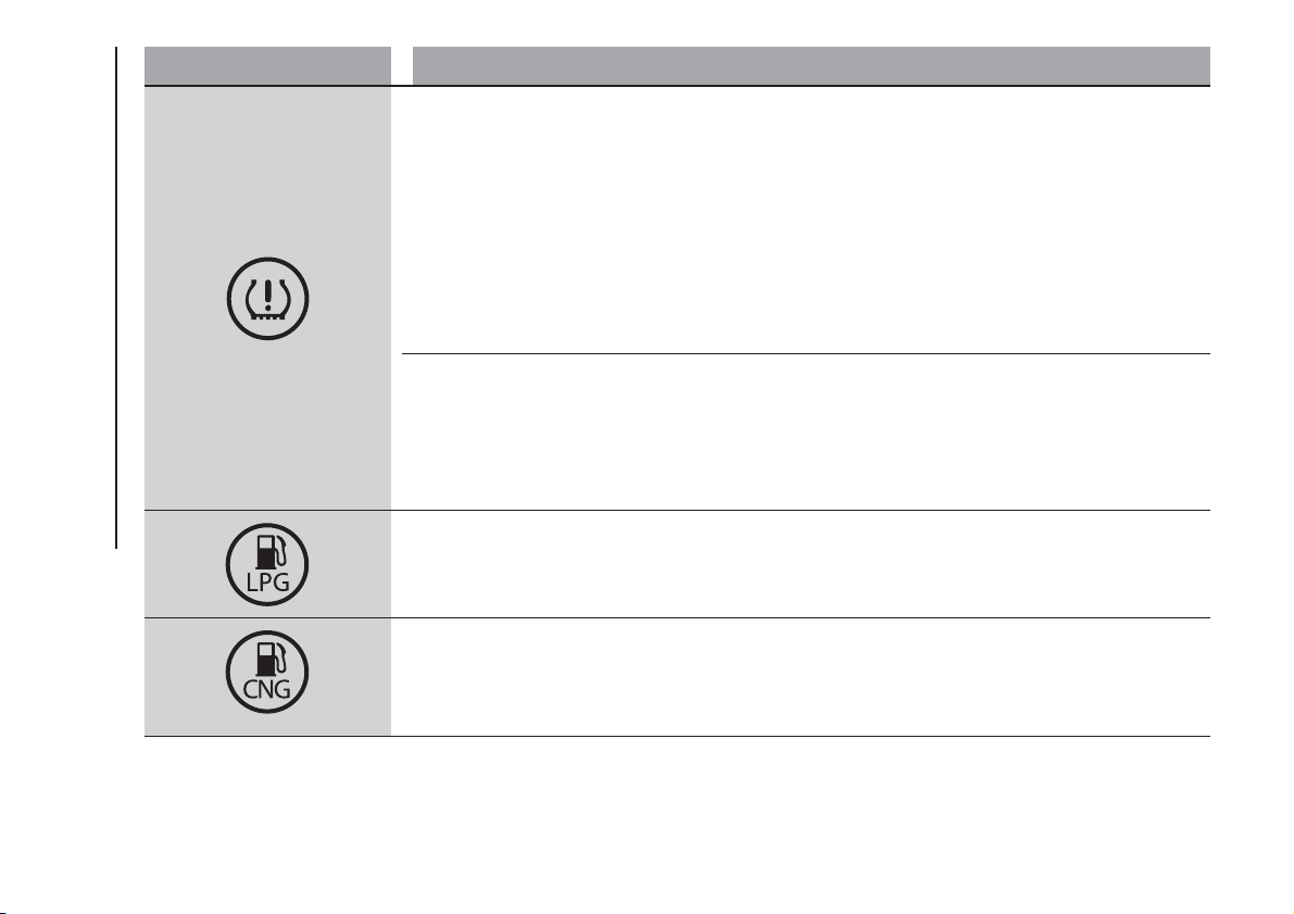
Warning light What it means
iTPMS
(for versions/markets, where provided)
Tyre pressure low
The warning light switches on constantly to indicate that the tyre pressure is lower than the recommended
value, in order to guarantee long tyre life and low fuel consumption, or to indicate a slow loss of pressure.
In this way the iTPMS warns the driver that one or more tyres may be flat and probably punctured. In this
case it is advisable to restore the correct pressure value. Once the normal operating conditions of the
vehicle are restored, carry out the Tyre reset procedure.
IMPORTANT Do not continue driving with one or more flat tyres as handling may be compromised. Stop
the vehicle, avoiding sharp braking and steering.
iTPMS failure/iTPMS temporarily deactivated
The warning light flashes for about 75 seconds and then stays on constantly (along with a dedicated
message on the display) to indicate that the system is temporarily deactivated or faulty. The system goes
back to normal operation when the operating conditions allow it. If this is not the case, carry out the Tyre
reset procedure after restoring the normal operating conditions.
If the malfunction warning persists, contact a Fiat Dealership as soon as possible.
LPG FUEL RESERVE
(for versions/markets, where provided)
The warning light switches on when the residual quantity of LPG drops below 1/5 of the tank capacity. On
certain versions a dedicated message is displayed.
METHANE RESERVE (Natural Power versions)
The warning light switches on when the residual quantity of Methane drops below 1/5 of the tank capacity.
On certain versions a dedicated message is displayed.
52
KNOWING THE INSTRUMENT PANEL
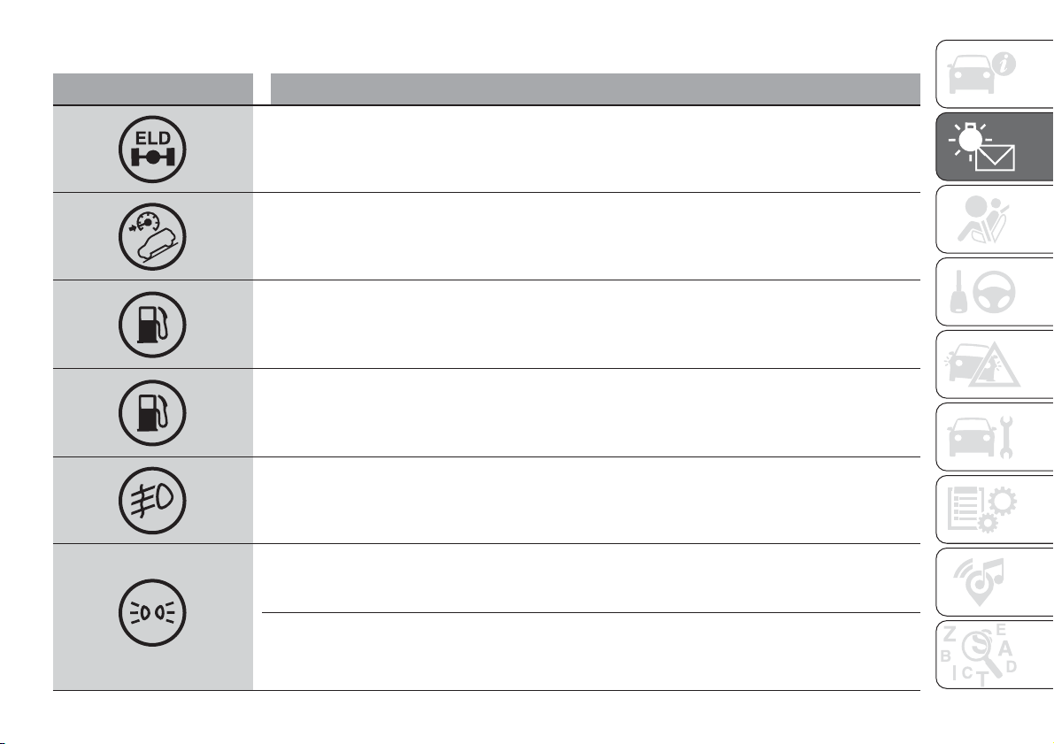
Green warning lights
Warning light What it means
ELD SYSTEM (for versions/markets, where provided)
The warning light on flashing indicates activation of the electronic locking differential (ELD) function.
GRAVITY CONTROL SYSTEM (Panda Cross 4x4 versions)
The warning light on constantly, along with a dedicated message on the display, indicates activation of the
Gravity Control function. Deactivation of the function is signalled by flashing of the warning light, by an
acoustic warning and by a dedicated message on the display.
PETROL/LPG SWITCHING
(for versions/markets, where provided)
Warning light on constantly: petrol operation.
Warning light off: LPG operation.
PETROL/METHANE SWITCHING
(for versions/markets, where provided)
Warning light on constantly: petrol operation.
Warning light off: Methane operation.
FOG LIGHTS
The warning light comes on when the front fog lights are turned on.
SIDE LIGHTS AND DIPPED BEAM HEADLIGHTS/FOLLOW ME HOME
Side lights and dipped beam headlights
The warning light switches on when the side lights or dipped headlights are turned on.
Follow Me Home
The warning light comes on, on some versions along with a dedicated message on the display, when the
"Follow me home" device is used.
53
Warning light What it means
LEFT DIRECTION INDICATOR
The warning light turns on when the direction indicator control lever is moved downwards or, together with
the right indicator, when the hazard warning light button is pressed.
RIGHT DIRECTION INDICATOR
The warning light turns on when the direction indicator control lever is moved upwards or, together with the
left indicator, when the hazard warning light button is pressed.
Blue warning lights
Warning light What it means
MAIN BEAM HEADLIGHTS
The warning light switches on when the main beam headlights are turned on.
Symbols and messages on the display
Symbol or message What it means
The symbol is displayed, along with a dedicated message, in the event of an LPG system failure.
In this case, contact a Fiat Dealership as soon as possible, running on petrol
The symbol is displayed, along with a dedicated message, in the event of a methane supply system failure.
In this case, contact a Fiat Dealership as soon as possible, running on petrol
54
KNOWING THE INSTRUMENT PANEL
Symbol or message What it means
FUEL LEVEL SENSOR FAILURE
The symbol appears and all the notches disappear in the event of fuel gauge sensor failure. Contact a Fiat
Dealership as soon as possible.
START&STOP
(For versions/markets, where
provided)
The message is displayed when the Start&Stop system is activated/deactivated by pressing the
button
in the central part of the dashboard.
With the Start&Stop system on, the LED on the button is off; if the system is deactivated the LED comes
on.
GRAVITY CONTROL
(Panda Cross 4x4 versions)
The activation, activation not permitted and deactivation of the Gravity Control system are shown on the
display.
SERVICE
When the next scheduled service is approaching, the word “Service” appears on the display, followed by
the number of kilometres or miles left. This is displayed automatically, with ignition key at MAR-ON, 2000
km (or equivalent value in miles) before servicing or, where provided, 30 days before servicing. It is also
displayed each time the key is turned to MAR-ON or, for versions/markets, where provided, every 200 km
(or equivalent value in miles).
Go to a Fiat Dealership, where the "Scheduled Servicing Plan" operations will be performed and the
message will be reset.
55
Symbol or message What it means
DUALOGIC TRANSMISSION
For versions equipped with "Dualogic" gearbox, the following messages can be displayed:
Reduce gear changes
Manual method unavailable
Automatic method unavailable
Clutch overheating
Depress brake pedal
Depress brake pedal - delayed ignition
Gear unavailable
Operation not admissible
Depress brake pedal and repeat operation
Positioning of the gear lever at N (neutral).
28) 29)
WARNING
28) If the messages remain on the display, contact the Fiat Dealership.
29) In order to safeguard the efficiency of the clutch, do not use the accelerator to keep the car stationary (e.g. when standing uphill); if the
clutch overheats it could damage it; use the brake pedal instead and only use the accelerator pedal when you decide to set off.
56
KNOWING THE INSTRUMENT PANEL
SAFETY
The chapter that you are about to read
is very important: it describes the
safety systems with which the vehicle is
equipped and provides instructions on
how to use them correctly
ACTIVE SAFETY SYSTEMS ............ 58
DRIVING ASSISTANCE SYSTEMS .. 64
OCCUPANT PROTECTION
SYSTEMS ....................................... 68
SEAT BELTS ................................... 68
SBR (SEAT BELT REMINDER)
SYSTEM ......................................... 70
PRE-TENSIONERS ......................... 71
CHILD PROTECTION SYSTEMS..... 73
SUPPLEMENTARY RESTRAINT
SYSTEM (SRS) - AIRBAG................ 83
57
ACTIVE SAFETY
SYSTEMS
ABS (Anti-lock Braking
System)
This system, which is an integral part of
the braking system, prevents one or
more wheels from locking and slipping
in all road surface conditions,
irrespective of the intensity of the
braking action, ensuring that the car
can be controlled even during
emergency braking.
IMPORTANT To obtain the maximum
efficiency of the braking system, a
bedding-in period of about 500 km is
needed: during this period it is better to
avoid sharp, repeated and prolonged
braking.
The ABS also integrates the following
systems: EBD (Electronic Braking Force
Distribution), MSR (Motor
Schleppmoment Regelung) and MBA
(Mechanical Brake Assist) (for
versions/markets, where provided).
System intervention
The driver can feel that the ABS system
has come into action because the
brake pedal pulsates slightly and the
system gets noisier: this is entirely
normal with the system operating.
44) 45) 46) 47) 48) 49) 50) 51) 52)
ESC (Electronic Stability
Control) SYSTEM
(for versions/markets, where provided)
This is an electronic system that
controls car stability in the event of loss
of tyre grip, helping maintain directional
control. The system is capable of
recognising potentially dangerous
situations in terms of the stability and
intervenes automatically on the brakes
in a differentiated manner for the four
wheels in order to provide a stabilising
torque.
The ESC system switches on
automatically when the engine is
started and cannot be switched off.
System intervention
The intervention of the system is
indicated by the flashing of the ESC
warning light on the instrument panel,
to inform the driver that the vehicle is in
critical stability and grip conditions.
53) 54) 55) 56) 57) 58)
HH (Hill Holder) SYSTEM
This system is an integral part of the
ESC system and facilitates starting on
slopes.
It is automatically activated in the
following conditions:
uphill: vehicle stationary on a road
with a gradient higher than 5%, engine
running, brake pressed and
transmission in neutral or gear other
than reverse engaged;
downhill: car stationary on a road
with a gradient of more than 5%,
engine running, brake pressed and
reverse gear engaged.
When setting off, the ESC system
control unit maintains the braking
pressure on the wheels until the torque
necessary for starting is reached, or
in any case for a maximum of 2
seconds, allowing your right foot to be
moved easily from the brake pedal to
the accelerator.
When the 2 seconds have elapsed,
without starting, the system is
automatically deactivated, gradually
releasing the braking pressure. During
this release stage, the typical
mechanical brake release noise can be
heard, indicating that the car is about
to move.
NOTE: The Hill Holder system is not
active with the handbrake engaged.
58
SAFETY
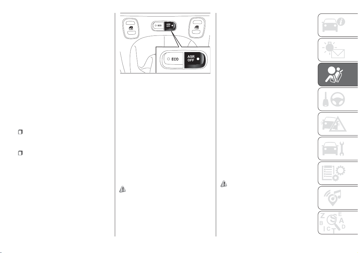
IMPORTANT The Hill Holder system is
not a parking brake, therefore do not
leave the vehicle without activating the
handbrake, switching off the engine,
and engaging first gear, with the vehicle
parked in safe conditions.
ASR (AntiSlip
Regulation) SYSTEM
It is an integral part of the ESC system.
It is automatically activated in the case
of drive wheels slipping, loss of grip
on wet roads (aquaplaning) and
acceleration on slippery, snowy or icy
roads, etc.
Depending on the slipping conditions,
two different control systems are
activated:
if the slipping involves both drive
wheels, the ASR intervenes reducing
the power transmitted by the engine;
if the slipping only involves one
of the drive wheels, it intervenes
automatically braking the wheel that is
slipping.
Engagement/disengagement of the
system
The ASR is switched on automatically
each time the engine is started.
While driving, the ASR can be switched
off and subsequently switched on
again by pressing the ASR OFF button
fig. 49.
On some versions, the intervention of
the system is indicated by a dedicated
message shown on the display. When
the system is not active, the LED on the
button ASR OFF turns on and, on
some versions, a message appears on
the display.
When the ASR is deactivated while
driving, the next time the car is started
the ASR is automatically activated.
When travelling on snowy roads with
snow chains, it may be helpful to turn
the ASR off: in fact, in these conditions,
the driving wheels skidding when
setting off gives you better traction.
59) 60) 61) 62) 63)
HBA (Hydraulic Brake
Assist) system
The HBA system is designed to
improve the car’s braking capacity
during emergency braking. The system
detects an emergency braking by
monitoring the speed and strength with
which the brake pedal is pressed,
thereby applying the optimal brake
pressure.
This can reduce the braking distance:
the HBA system therefore completes
the ABS.
Maximum assistance from the HBA
system is obtained pressing the brake
pedal very quickly. In addition, the
brake pedal must be pressed
continuously during braking, avoiding
intermittent presses, to benefit from the
system.
Do not reduce pressure on the brake
pedal until braking is no longer
necessary.
The HBA system is deactivated when
the brake pedal is released.
64) 65) 66)
49
F1D0038
59

ELD (Electronic Locking
Differential) SYSTEM
(Panda Cross 4x4 and Panda 4x4
versions)
The ELD system allows the drive force
to be evenly distributed over the same
axle when one or both wheels are
slipping. The ELD acts by braking the
wheels with poor grip (or those slipping
more than the others), thereby
transferring the drive force to those
which have greater grip on the ground.
The system operates at speeds below
50 km/h. Above this speed, it is
automatically deactivated and it is
reactivated when the speed falls below
50 km/h.
The activation of the ELD system
involves the following functions being
switched on:
inhibition of the ASR function, in
order to fully exploit the engine torque;
differential lock effect on the front
and rear axles, via the braking system,
to improve drive on uneven surfaces.
Enabling the system
To arrange operation of the ELD system
press button A fig. 50 (Panda 4x4
versions) or turn the ring fig. 51 to the
right (Panda Cross 4x4 versions) and
keep it in this position until LED 2
on the selector lights up.
System intervention
The
warning light on the instrument
panel flashes to signal that the system
has intervened.
If the space-saver wheel is used
If the space-saver wheel is used, the
control unit for 4x4 drive detects its
presence (via the wheel speed signals)
and reduces the intervention of the
four-wheel drive mode to a minimum,
while guaranteeing the agility of the
vehicle. No fault/alarm signal is
displayed on the instrument panel or on
the display.
Disabling the system
To disable the system, press button A
fig. 50 (Panda 4x4 versions) or turn
the ring to the left fig. 51 (Panda Cross
4x4 versions) and keep it in this position
until LED 1 on the selector lights up.
GRAVITY CONTROL
SYSTEM
(Panda Cross 4x4 versions)
IMPORTANT This function can be
activated only with "Off Road" mode
activated.
It is an integral part of the ESC system
and is aimed at keeping the vehicle at a
constant speed during a descent,
operating autonomously on the brakes
in various ways at the same time. In this
way, the Gravity Control function
assists the driver on steep gradients in
low-grip conditions and/or on rough
terrain.
50
F1D0122
51
F1D0116
60
SAFETY
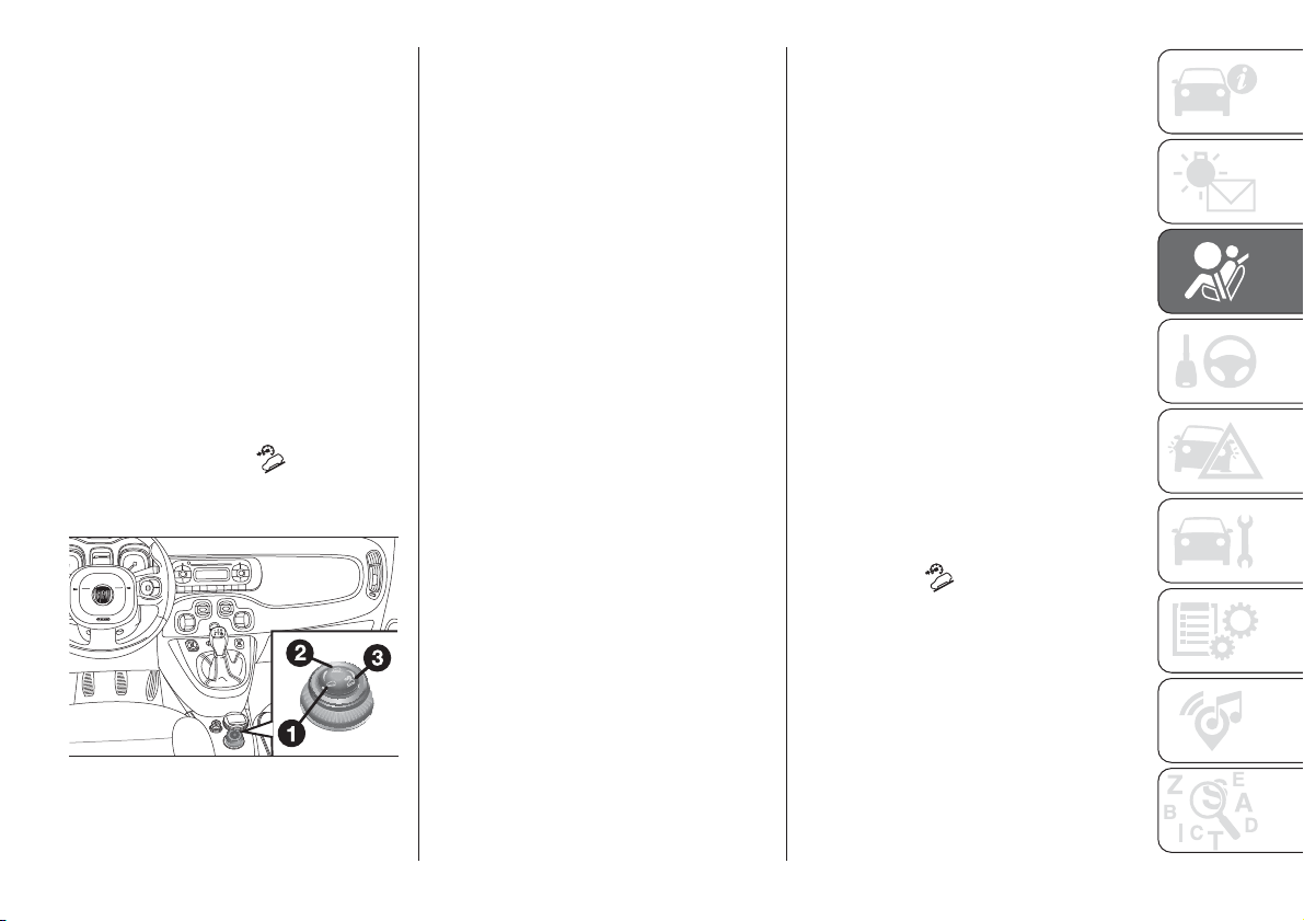
Noise and vibrations coming from the
wheel sides (brakes) when the Gravity
Control system is activated are normal.
IMPORTANT The system does not
relieve the driver of the responsibility of
controlling the vehicle and does not
replace attention while driving. The
driver of the vehicle takes the complete
responsibility for the consequences of
their actions and of an incorrect and not
responsible use of the vehicle.
Enabling the system
To arrange operation of the Gravity
Control system, turn ring fig. 52, with
LED 2 on, to the right, and keep it
in this position until LED 3 on the
selector lights up. The
warning light
comes on in the instrument panel and
the dedicated message is displayed.
IMPORTANT System intervention
set-up can be engaged only with "Off
Road" mode activated.
System intervention
You must travel at a speed slower than
25 km/h for the system to activate.
After reaching the desired speed,
release the accelerator and brake
pedals completely. If you want to
increase/decrease the speed, press the
accelerator/brake pedals again.
IMPORTANT The system is also
available for very low speeds between 5
km/h and 9 km/h, but in this interval
the gearbox must be set to neutral to
prevent engine stalling.
IMPORTANT For speeds above 9 km/h,
the Gravity Control system must be
used with a gear that is suitable for the
set speed, in order to prevent possible
engine stalling. While the Gravity
Control system is operating it is also
possible to take control of the vehicle
again by pressing the brake and
accelerator pedals. If the Gravity
Control is not available when system
intervention set-up is engaged, this
could be due to brake overheating. In
this case, wait for a few minutes.
IMPORTANT The Gravity Control
system is available for speeds between
5 km/h and 25 km/h. It is advisable to
use the system in low gears (first,
second and third).
IMPORTANT On level ground in urban
areas it is advisable to deactivate the
Gravity Control system intervention
set-up, since for speeds below 25 km/h
in some usage conditions, such as
when setting off, shifting gear and
driving over road humps without using
the accelerator pedal, the system might
activate.
Disabling the system
To deactivate the system, turn the ring
fig. 52 to the left, keeping it in this
position until LED 3 on the selector
switches off.
IMPORTANT If the braking system
overheats the system will deactivate
through a gradual release of the braking
pressure, leaving vehicle control to the
driver. Deactivation of the Gravity
Control system is accompanied by
flashing of the
warning light, by a
dedicated message on the display and
an acoustic warning. To reactivate
the system intervention set-up wait for
the system to cool down and turn
the ring nut again.
52
F1D0116
61
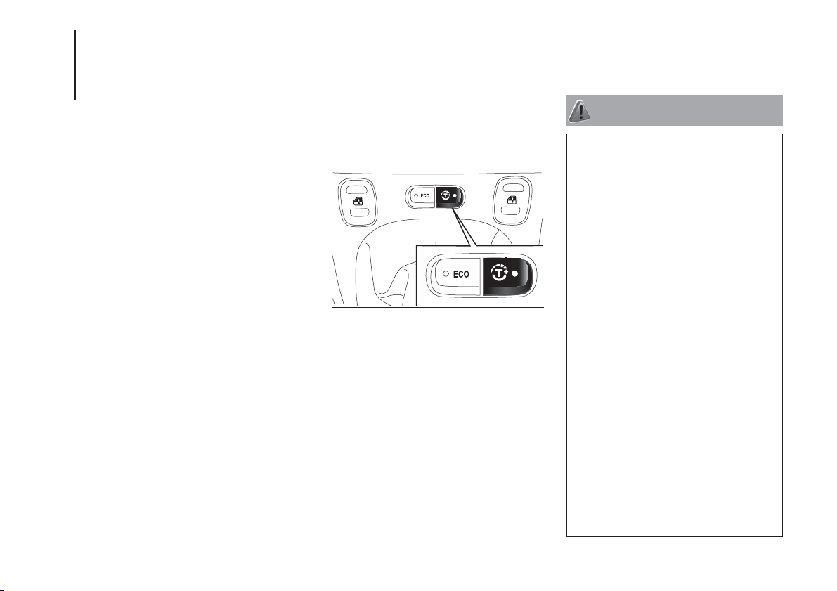
IMPORTANT The Gravity Control
system is deactivated when exceeding
25 km/h and at speeds lower than
50 km/h it remains enabled to be
reactivated when the speed returns
under 25 km/h. In this case, the
indication on the instrument panel is
switched off and the LED on the ring
stays on. If car speed exceeds 50
km/h, the Gravity Control system
completely deactivates and each
individual action made by the system
on the brakes is blocked. To reactivate
it, turn the ring nut again when the
speed is again below 25 km/h.
T+ (Traction Plus)
SYSTEM
(for versions/markets, where provided)
Traction Plus is a driving aid, useful
for setting off in poor grip conditions
(snow, ice, mud, etc.) which allows the
drive force to be distributed in the
best way over the front axle when one
wheel is slipping.
Traction Plus acts by braking the
wheels with poor grip (or those slipping
more than the others), thereby
transferring the drive force to those
which have greater grip on the ground.
Engagement/disengagement
The system is deactivated when
starting. To activate the Traction Plus
system, press the T+ button fig. 53: the
LED on the button switches on; the
display shows a dedicated message. To
disengage the system press the T+
button again.
Operation
This function operates under a
threshold of 30 km/h. Over this speed,
it is automatically deactivated (the
LED on the button is still on) and it is
reactivated again when the speed
is below 30 km/h.
The activation of the Traction Plus
system causes the differential locking
effect on the front axle, through the
braking system, to improve traction on
irregular grounds.
If the Traction Plus system is faulty, the
ESC warning light on the instrument
panel switches on constantly.
WARNING
44) The ABS gets the most from the
available grip, but it cannot improve it; you
should therefore take every care when
driving on slippery surfaces and not take
unnecessary risks.
45) When the ABS cuts in and you feel the
brake pedal pulsating, do not remove
your foot, but keep the pedal pushed
down; in doing so you, will stop in the
shortest distance possible under the road
conditions at the time.
46) If the ABS system intervenes, this
indicates that the traction of the tyres on
the road is nearing its limit. You must slow
down to a speed compatible with the
available traction.
47) To obtain the maximum efficiency of
the braking system, a bedding-in period of
about 500 km is needed: during this period
it is better to avoid sharp, repeated and
prolonged braking.
48) The ABS cannot overrule the natural
laws of physics, and cannot increase
the grip available according to the
condition of the road.
49) The ABS cannot prevent accidents,
including those due to excessive speed on
corners, driving on low-grip surfaces or
aquaplaning.
53
F1D0039
62
SAFETY

50) The capability of the ABS must never
be tested irresponsibly and dangerously, in
such a way as to compromise personal
safety and the safety of others.
51) For the correct operation of the ABS,
the tyres must of necessity be the same
make and type on all wheels, in perfect
condition and, above all, of the prescribed
type and dimensions.
52) When the Mechanical Brake Assist
intervenes, noises may be heard from the
system. This is normal. In any case, while
braking keep the brake pedal firmly
depressed.
53) For the correct operation of the ESC
system, the tyres must necessarily be
of the same make and type on all wheels,
in perfect condition and, above all, of
the prescribed type and size.
54) The ESC functions even when the
space-saver wheel is being used. Always
remember that the space-saver wheel,
being smaller than the original wheel,
provides less grip.
55) ESC performance features must not
induce the driver to take unnecessary
or unfounded risks. Your driving style must
always be suited to the road conditions,
visibility and traffic. The driver is, in any
case, responsible for safe driving.
56) The ESC system cannot alter the
natural laws of physics, and cannot
increase grip, which depends on the
condition of the road.
57) The ESC system cannot prevent
accidents, including those due to excessive
speed on corners, driving on low-grip
surfaces or aquaplaning.
58) The capability of the ESC system must
never be tested irresponsibly and
dangerously, in such a way as to
compromise personal safety and the safety
of others.
59) For the correct operation of the ASR
system, the tyres must of necessity be the
same make and type on all wheels, in
perfect condition and, above all, of the
prescribed type and dimensions.
60) Do not take unnecessary risks, even if
your vehicle is fitted with an ASR system.
Your driving style must always be suited to
the road conditions, visibility and traffic.
The driver is, in any case, responsible for
safe driving.
61) The ASR cannot overrule the natural
laws of physics, and cannot increase
the grip available according to the
condition of the road.
62) The ASR system cannot prevent
accidents, including those due to excessive
speed on corners, driving on low-grip
surfaces or aquaplaning.
63) The capability of the ASR must never
be tested irresponsibly and dangerously, in
such a way as to compromise personal
safety and the safety of others.
64) The HBA system cannot increase tyre
grip on the road over the limits imposed by
laws of physics: always drive carefully
according to the conditions of the road
surface.
65) The HBA system cannot prevent
accidents, including those due to excessive
speed on bends, travelling on low-grip
surfaces or aquaplaning.
66) The HBA system is an aid for the driver,
who must always pay full attention while
driving. The responsibility always rests with
the driver. The features of the HBA system
must never be tested in imprudent or
dangerous ways, with the possibility of
putting the safety of the driver, occupants
or other road users at risk.
63
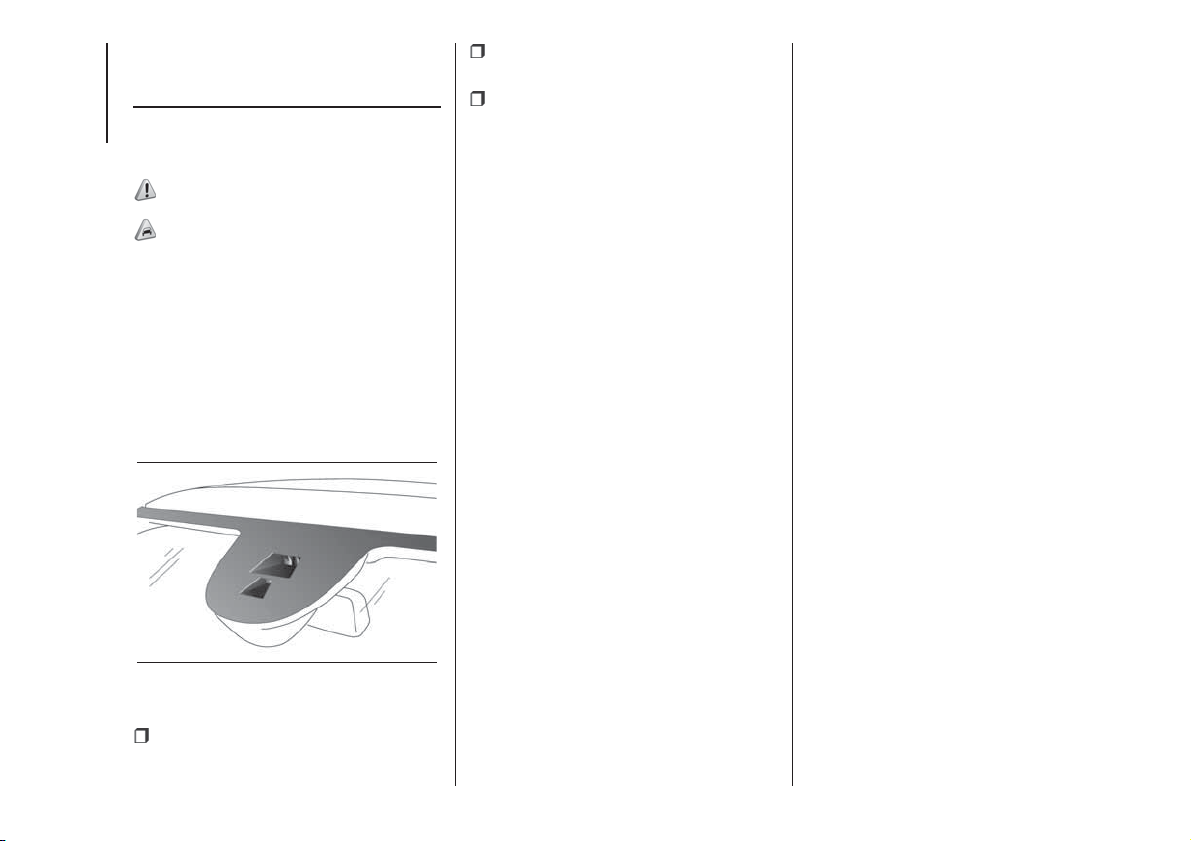
DRIVING
ASSISTANCE
SYSTEMS
CBC (City Brake
Control) system
(for versions/markets, where provided)
67) 68) 69) 70) 71)
30) 31) 32) 33) 34) 35) 36)
This is a driving assistance system,
which includes a laser sensor, located
in the upper part of the windscreen
fig. 54, that can detect the presence of
nearby cars in front of the vehicle and,
in the case of an imminent collision,
intervenes automatically, braking the
vehicle to prevent the impact or
mitigate its effects.
The system is only active if:
the ignition key is at MAR;
the vehicle speed is between 5 and
30 km/h;
the front seat belts are fastened.
Anyway, the system can be deactivated
(then reactivated) through the Setup
Menu on the display.
The system intervenes if there is risk of
imminent collision and the driver does
not press the brake pedal promptly.
If the system detects that the vehicle
ahead could be hit, it may prepare the
vehicle to a possible emergency
braking.
If the driver does not carry out any
action to prevent the collision, the
system may automatically slow down
the vehicle, in order to prepare it to
a possible impact.
When there is risk of impact, if the
action on the brake pedal by the driver
is not sufficient, the system may
intervene in order to improve
the reaction of the braking system,
therefore reducing vehicle speed
further.
When driving uphill on a steep slope,
the system may intervene, activating
the braking system.
Versions equipped with Start&Stop
system: at the end of the automatic
braking, the Start&Stop system will
activate as described in the "Start&Stop
system" paragraph of the "Starting
and driving" chapter.
Versions equipped with manual
gearbox: at the end of the automatic
braking the engine may stall and turn
off, unless the driver presses the clutch
pedal.
Versions equipped with "Dualogic"
gearbox (for versions/markets, where
provided): at the end of braking the last
gear stored remains engaged.
IMPORTANT Both on versions
equipped with manual gearbox and on
those with "Dualogic" gearbox (for
versions/markets, where provided),
after the vehicle is stopped the brake
calipers may be stuck for about 2
seconds for safety reasons. Make sure
you press the brake pedal if the vehicle
moves slightly forwards.
IMPORTANT The system does NOT
activate when reverse is engaged. The
system does NOT activate if the front
seat belts are not fastened.
Engagement/disengagement
The system can be deactivated (then
reactivated) through the Setup Menu on
the display.
54
F1D0041
64
SAFETY
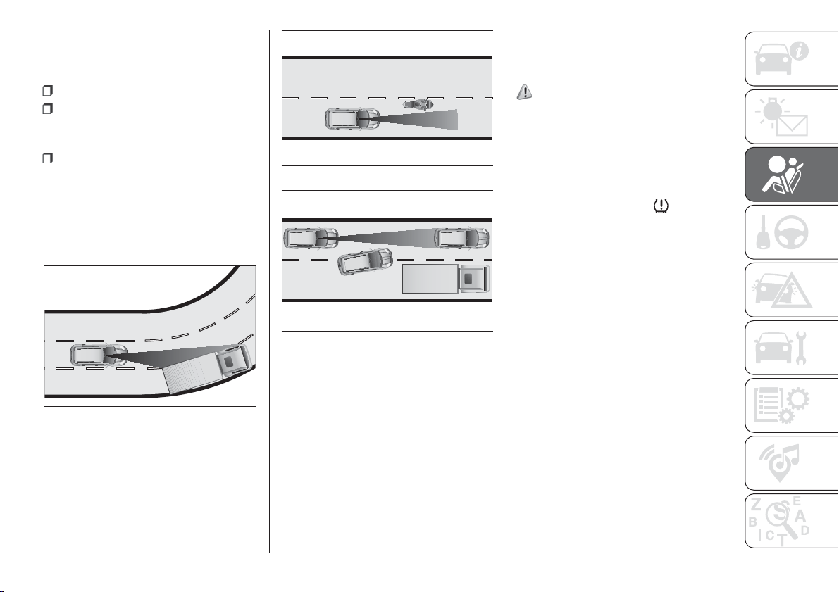
Driving in special conditions
In certain driving conditions, such as,
for example:
driving close to a bend (see fig. 55);
vehicles with small dimensions
and/or not aligned in the driving lane
(see fig. 56);
lane change by other vehicles (see
fig. 57);
system intervention can be unexpected
or delayed. The driver must therefore
be very careful, keeping control of
the vehicle to drive in complete safety.
IMPORTANT If you are driving on roads
close to trees with protruding branches
it is advisable to deactivate the system
to prevent the branches at the height
of the bonnet or the windscreen from
interfering with the system.
iTPMS System (indirect
Tyre Pressure
Monitoring System)
(for versions/markets, where provided)
72) 73) 74) 75) 76) 77)
The car can be equipped with the
iTPMS (indirect Tire Pressure
Monitoring System) which monitors the
tyre inflation status thanks to wheel
speed sensors.
The system warns the driver if one or
more tyres are flat by the
warning
light continuously lit on the instrument
panel and a dedicated warning
message on the display.
If one tyre only is flat, the system can
indicate its position: it is in any case
recommended to check the pressure
on all four tyres.
This indication is displayed also when
turning the engine off and on again until
the RESET procedure is carried out.
Reset procedure
The iTPMS needs an initial "self-
learning" phase (with length depending
on the driving style and road conditions:
optimal conditions being driving on a
straight road at 80 km/h for at least 20
minutes) which starts when the Reset
procedure is carried out.
55
F1D0042
56
F1D0043
57
F1D0044
65
The Reset procedure must be carried
out:
each time tyre pressure is modified;
when even only one tyre is changed;
when tyres are rotated/inverted;
when the space-saver wheel is
fitted.
Before carrying out the Reset
procedure, inflate the tyres to the rated
pressure values specified in the inflation
pressure table (see "Wheels" paragraph
in the "Technical specifications"
chapter).
If the Reset procedure is not carried
out, in all above cases, the
warning
light may give false indications on
one or more tyres.
To carry out the RESET procedure, with
the car stopped and the ignition device
at MAR, use the Main Menu as follows:
briefly press the button: the
display will show Reset;
press the button or the
button to select ("Yes" or "No");
briefly press the button: the
display will show "Confirm";
press button or to select
("Yes" to Reset or "No" to exit the video
page);
press the button again to return
to the standard screen or to the main
menu according to where you are in the
menu.
At the end of the Reset procedure, the
display will show the message "Reset
saved", indicating that self-learning has
started.
Operating conditions
The system is active for speeds above
15 km/h.
In a few situations such as sporty
driving, particular conditions of the road
surface (e.g. icy, snowy, unsurfaced
roads...) the signalling may be delayed
or partial in detecting the contemporary
deflation of more than one tyre.
Under special conditions (e.g. vehicle
loaded asymmetrically on one side,
towing a trailer, damaged or worn tyre,
fitting the space-saver wheel, use of the
"Fix&Go" kit, fitting snow chains, fitting
different tyres on the axles) the system
may give false indications or be
temporarily deactivated.
If the system is temporarily deactivated,
the warning light
flashes for about
75 seconds and then is continuously
on; at the same time, the display shows
a dedicated message.
This warning is also displayed after the
engine has been switched off and
then on again if the correct operating
conditions are not restored.
WARNING
67) The system is an aid for the driver, who
must always pay full attention while
driving. The responsibility always rests with
the driver, who must take into account
the traffic conditions in order to drive
in complete safety. The driver must always
maintain a safe distance from the vehicle
in front.
68) If the driver depresses the brake pedal
fully or carries out a fast steering during
system operation, the automatic braking
function may stop (e.g. to allow a possible
manoeuvre to avoid the obstacle).
69) The laser beam is not visible at the
naked eye. Do not look directly, or with
optical instruments (e.g. lenses), at the
laser beam from a distance lower than 10
cm: this may cause damage to the sight.
The laser beam is also present when
the key is at MAR but its operation is off,
not available or manually deactivated
with the display Setup Menu.
70) The system intervenes on vehicles
travelling in the same lane. Small sized
vehicles (e.g. bicycles or motorbikes)
or people, animals and things (e.g.
pushchairs) and more in general all those
obstacles with a low reflection of the light
emitted by the laser (e.g. vehicles soiled
with mud) are not taken into consideration.
66
SAFETY
71) If the car must be placed on a roller
bench (at a speed within 5 and 30 km/h)
for maintenance interventions or if it is
washed in an automatic roller washing
tunnel with an obstacle in the front part
(e.g. another car, a wall or another
obstacle), the system may detect its
presence and activate. In this case the
system must be deactivated through the
display Setup Menu.
72) If the system signals a pressure
decrease on a specific tyre, it is
recommended to check the pressure on all
four tyres.
73) The iTPMS does not relieve the driver
from the obligation to check the tyre
pressure every month; it is not to
be considered a system to replace
maintenance or a safety system.
74) Tyre pressure must be checked with
tyres cold. Should it become necessary for
whatever reason to check pressure with
warm tyres, do not reduce pressure even
though it is higher than the prescribed
value, but repeat the check when tyres are
cold.
75) The iTPMS cannot indicate sudden
tyre pressure drops (for example when
a tyre bursts). In this case, stop the vehicle,
braking with caution and avoiding abrupt
steering.
76) The system only warns that the tyre
pressure is low: it is not able to inflate
them.
77) Insufficient tyre inflation increases fuel
consumption, reduces the tread duration
and may affect the capacity to drive safely.
WARNING
30) The laser sensor may have limited or
absent operation due to weather
conditions such as: heavy rain, hail, thick
fog, heavy snow, formation of ice layers on
the windscreen.
31) Sensor operation may also be
compromised by the presence of dust,
condensation, dirt or ice on the
windscreen, by traffic conditions (e.g.
vehicles that are driving not aligned with
you car, vehicle driving in a transverse
or opposite way on the same lane, bend
with a small radius of curvature), by road
surface conditions and by driving
conditions (e.g. off-road driving). Make sure
the windscreen is always clean. Use
specific detergents and clean cloths to
avoid scratching the windscreen. The
sensor operation may also be limited or
absent in some driving, traffic and road
surface conditions.
32) Projecting loads on the roof of the car
may interfere with the correct operation
of the sensor. Before starting make sure
the load is correctly positioned, in order not
to cover the sensor operating range.
33) If the windscreen must be replaced
due to scratches, chipping or breakage,
contact exclusively a Fiat Dealership.
Do not replace the windscreen on your
own, risk of malfunction! It is advisable to
replace the windscreen if it is damaged
in the laser sensor area.
34) Do not tamper nor operate on the laser
sensor. Do not close the openings in the
aesthetic cover located under the interior
rear view mirror. In the event of a sensor
failure, contact a Fiat Dealership.
35) Do not cover the operating range of the
sensor with stickers or other objects. Also
pay attention to other objects on the
bonnet (e.g. a layer of snow) and make
sure they do not interfere with the light
emitted by the laser.
36) If a trailer or a vehicle is towed the
system must be deactivated with the
display Setup Menu.
67
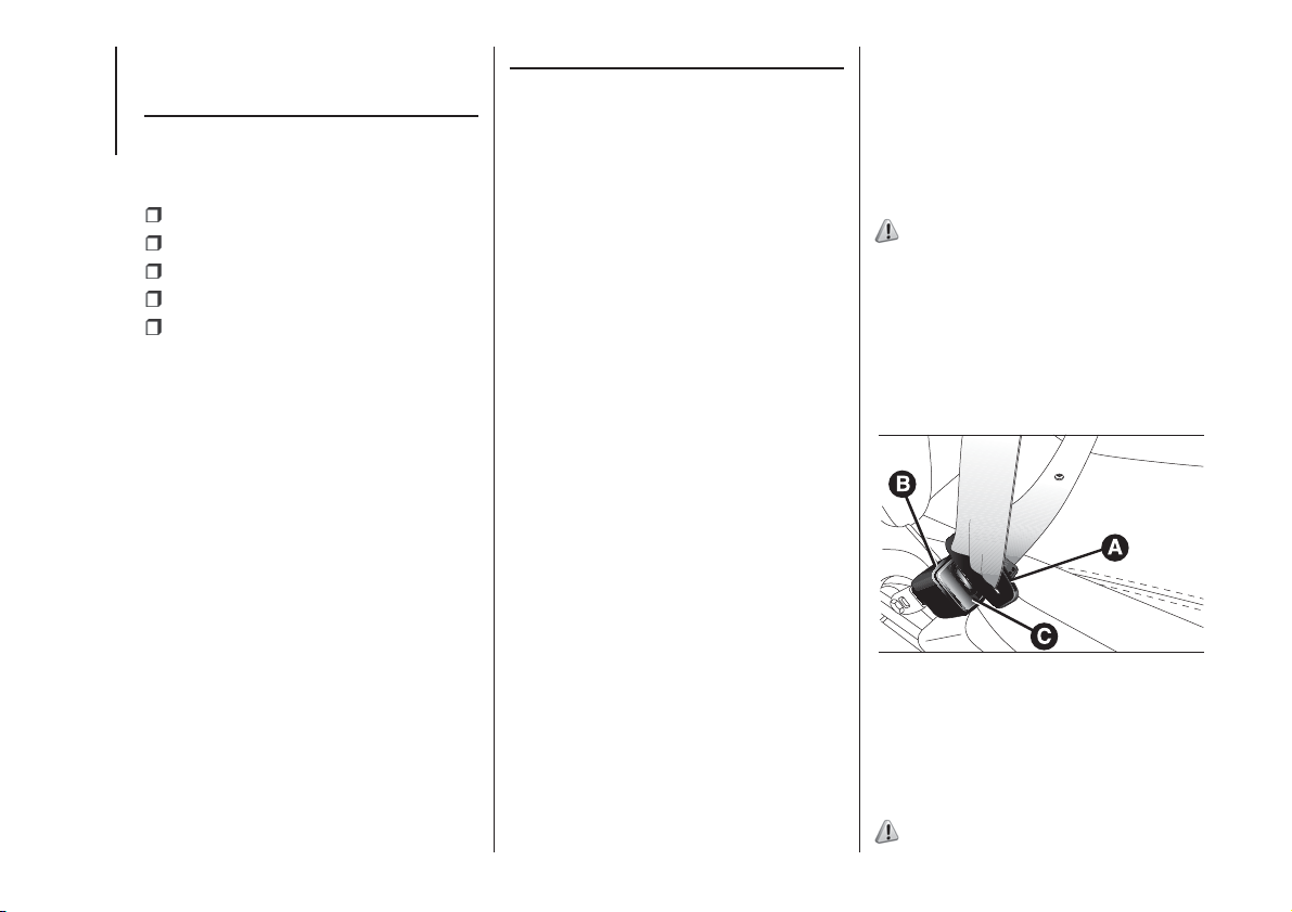
OCCUPANT
PROTECTION
SYSTEMS
The most important safety equipment
of the vehicle comprises the following
protection systems:
seat belts;
SBR (Seat Belt Reminder) system;
head restraints;
child restraint systems;
front airbags and side bags.
Read the information given the
following pages with the utmost care. It
is of fundamental importance that the
protection systems are used in the
correct way to guarantee the maximum
possible safety level for the driver and
the passengers.
For the description of the headrest
adjustment see the "Headrests"
paragraph in the "Knowing your
vehicle" chapter.
SEAT BELTS
USING THE SEAT BELTS
All vehicle seats are equipped with seat
belts with three anchor points and a
retractor. The reel mechanism operates
locking the belt in the event of sharp
braking or strong deceleration due
to an impact. This allows the belt strap
to slide freely and to adapt to the body
of the occupant. In the event of an
accident, the belt will lock reducing the
risk of impact inside the passenger
compartment and of being projected
outside the car.
The driver is responsible for respecting,
and ensuring that all the other
occupants of the vehicle also respect,
the local laws in force in relation to
the use of the seat belts.
Always fasten the seat belts before
setting off
The belt should be worn keeping the
torso straight and rested against the
backrest.
To fasten the seat belts, hold tongue A
fig. 58 and insert it into buckle B, until
it clicks into place. On removal, if the
belt jams, let it rewind for a short
stretch, then pull it out again without
jerking.
To unfasten the seat belts, press button
C. Guide the seat belt with your hand
while it is rewinding, to prevent it from
twisting. Through the retractor, the
belt automatically adapts to the body of
the passenger wearing it, allowing
freedom of movement.
78)
The retractor may lock when the vehicle
is parked on a steep slope: this is
perfectly normal. Furthermore, the
retractor mechanism locks the belt if it
is pulled sharply or in the event of
sudden braking, collisions and
high-speed bends.
The rear seat is fitted with inertia seat
belts with three anchor points and a
retractor. Wear the rear seat belts
as shown in fig. 59 (4-seater versions)
or fig. 60 (5-seater versions).
79) 80) 81)
58
F1D0050
68
SAFETY
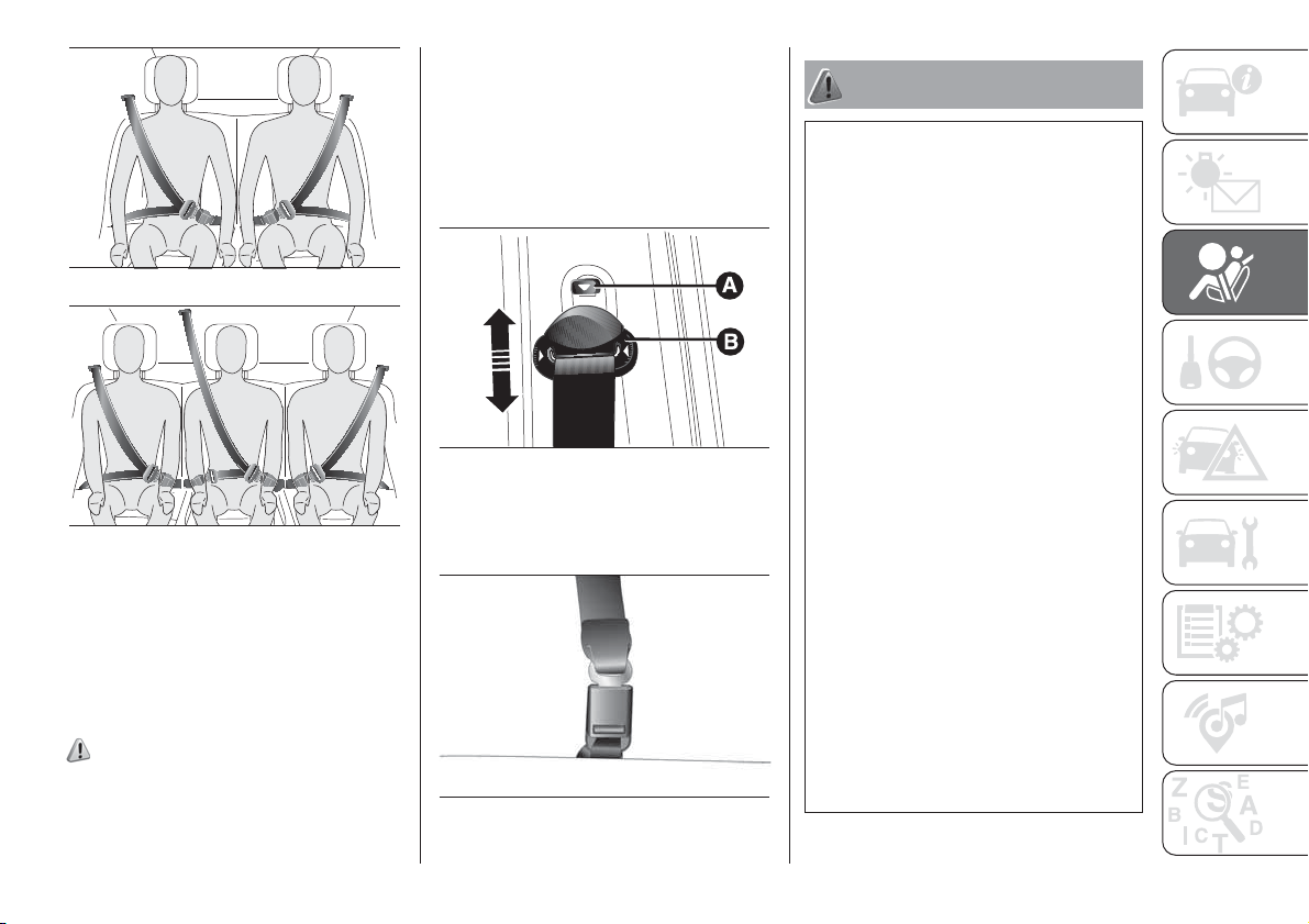
IMPORTANT When putting the back
seat to its normal position, make sure
the seat belts are positioned so they are
ready to use.
ADJUSTING THE SEAT
BELT HEIGHT
(for versions/markets, where provided)
82) 83)
Four different adjustments in height are
provided. To adjust, press button A
fig. 61 and raise or lower handle B.
Always adjust the height of the seat belt
to fit the person wearing it: this
precaution could greatly reduce the risk
of injury in the case of collision.
Correct adjustment is obtained when
the belt passes approximately half way
between the shoulder and the neck.
For some versions, front seat belts have
just one fixed anchor point located on
the door pillar.
WARNING
78) Never press button C fig. 58 when
travelling.
79) Remember that in the event of an
accident, the rear seat passengers not
wearing seat belts are exposed to a very
serious risk and also represent a serious
danger for the front seat occupants.
80) The rear central seat belt (for
versions/markets where provided) is
provided with a service buckle fig. 62. Do
not use the seat belt with the service
buckle not fastened. In this case there is a
high risk of injury or death in the event of
an accident. Before using the belt, always
make sure that the service buckle is
correctly fastened.
81) The rear left and right side belts are
provided with an adjustment device for the
metal tongue position (metal hook). Adjust
the tongue position with respect to the seat
belt to improve comfort and reduce noise
inside the passenger compartment.
82) Make height adjustment of the seat
belts when the car is stationary.
83) After height adjustment, always check
that the cursor to which the ring is fastened
is locked in one of the preset positions. To
do this, with button A fig. 61 released,
exert further pressure downwards to allow
the locking device to click if the grip has
not been released in one of the possible
positions.
59
F1D0051
60
F1D0052
61
F1D0053
62
F1D0777
69
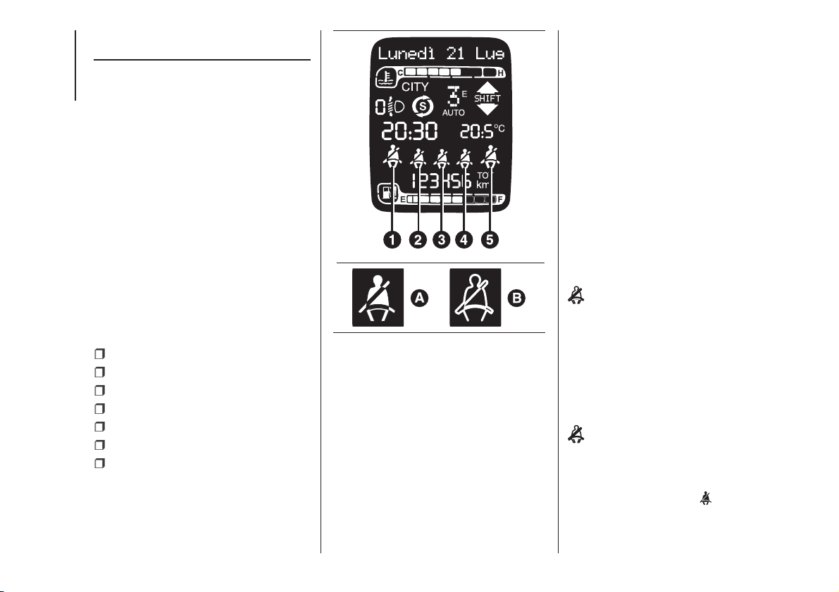
SBR (Seat Belt
Reminder) SYSTEM
The SBR system warns the passengers
of the front and rear (for versions/
markets, where provided) seats if their
seat belt is not fastened.
The system signals unfastened seat
belts with visual warnings (warning
lights on in the instrument panel and
icons on the display) and an acoustic
signal (see the following paragraphs).
Contact a Fiat Dealership to deactivate
this acoustic warning permanently.
The acoustic warning can be
reactivated at any time through the
display Setup Menu.
Seat belts warning light operation
The icons shown on the display fig.
63 indicate:
1: front left seat belt;
2: rear left seat belt;
3: rear central seat belt;
4: rear right seat belt;
5: front right seat belt;
A: seat belt not fastened;
B: seat belt fastened;
With driver and/or passenger side (with
passenger present) seat belts
unfastened, when 20 km/h are
exceeded or when travelling at a speed
between 10 and 20 km/h for longer
than 5 seconds, an acoustic signal
cycle will be started for the front seats
(continuous acoustic signal for 6
seconds followed by a 90 second
beep) and the warning light will flash.
Once the cycle is complete, the
warning lights stay on with a fixed light
until the vehicle is turned off or the
seat belt fastened.
If the seat belt is unfastened again while
travelling, the acoustic warning restarts
as described previously and the
icon is displayed.
For the rear seats, the reminder cycle is
only activated when any seat belt is
unfastened together with an acoustic
warning (three beeps). If the condition
of any (front or rear) seat belt changes,
also the condition of the other
(front/rear) seat belts is reported.
The visual indication (display of the
icon) will start and stop
independently for each warning light if
several seat belts are unfastened.
The visual indication will change
condition (display of the
icon) after
the corresponding seat belt has been
fastened again.
63
F1D0054
70
SAFETY
IMPORTANT When the ignition key is
turned to MAR, if all the front and
rear belts are already fastened the
warning lights will be displayed for
30 seconds.
PRE-TENSIONERS
84) 85) 86) 87)
37)
The vehicle is equipped with front seat
belt pretensioners, which draw back
the seat belts by several centimetres in
the event of a strong frontal impact.
This guarantees the perfect adherence
of the seat belts to the occupant's
bodies before the retention action
begins.
It is evident that the pretensioners have
operated when the belt withdraws
towards the retractor. This vehicle is
also equipped with a second
pretensioner (in the kick plate area). Its
activation is signalled by the shortening
of the metal cable.
A slight discharge of smoke may be
produced during the activation of the
pretensioner which is not harmful and
does not involve any fire hazard.
The pretensioner does not require any
maintenance or lubrication. Anything
that modifies its original conditions
invalidates its efficiency.
If, due to unusual natural events (floods,
sea storms, etc.), the device has been
affected by water and/or mud, contact
a Fiat Dealership to have it replaced.
IMPORTANT To obtain the highest
degree of protection from the action of
the pretensioner, wear the seat belt
tight to the chest and pelvis.
LOAD LIMITERS
To increase occupant safety, the
retractors contain a load limiter to dose
the force acting on the chest and
shoulders during the belt restraining
action in the case of frontal collisions.
GENERAL
INSTRUCTIONS FOR
USING THE SEAT BELTS
Seat belts are also to be worn by
pregnant women: the risk of injury in
the case of impact is greatly reduced
for them and the unborn child if they
are wearing a seat belt. Pregnant
women must position the lower part of
the belt very low down so that it passes
over the pelvis and under the
abdomen (see fig. 64). While pregnancy
increases, the driver must adjust both
seat and steering wheel to have full
control over the vehicle (pedals and
steering wheel should be easily
accessed). The maximum clearance
should be kept between the abdomen
and the steering wheel.
71

The seat belt must not be twisted. The
upper part must pass over the shoulder
and cross the chest diagonally. The
lower part must adhere to the pelvis (as
shown in fig. 65) rather than the
abdomen of the occupant. Do not use
devices (clips, etc.) to hold the seat belt
away from your body.
Each seat belt must be used by only
one person. Never travel with a child
sitting on the passenger's lap and
a single belt to protect them both fig.
66. In general, do not place any objects
between the person and the belt.
SEAT BELTS
MAINTENANCE
For keeping the seat belts in efficient
conditions, carefully observe the
following warnings:
always use the seat belt with the
strap well stretched and not twisted;
make sure that it is free to run without
obstructions;
check seat belt operation as follows:
attach the seat belt and pull it hard;
replace the belt after an accident of
a certain severity even if it does not
appear to be damaged. Always replace
the seat belt if the pretensioners were
deployed;
prevent the retractors from getting
wet: their correct operation is only
guaranteed if water does not get inside;
replace the seat belt when it shows
wear or cuts;
to clean the belt, wash by hand with
water and neutral soap, rinse and
leave to dry in the shade. Do not use
strong detergents, bleach, paints or any
other chemical substance which could
damage the belt fibres.
WARNING
84) The pretensioner may be used only
once. Contact a Fiat Dealership to have it
replaced after it has been deployed.
85) For maximum safety, keep the backrest
upright, lean back into it and make sure
the seat belt fits closely across your chest
and pelvis. Always fasten the seat belts
on both the front and the rear seats!
Travelling without wearing seat belts will
increase the risk of serious injury and even
death in the event of an accident.
86) Removing or tampering with seat belt
and pretensioner components is strictly
prohibited. Any intervention on these
components must be performed by
qualified and authorised technicians.
Always go to a Fiat Dealership.
64
F1D0123
65
F1D0124
66
F1D0125
72
SAFETY
87) If the belt has been sharply pulled, for
example as the result of an accident, the
seat belt, together with the anchoring
devices, the anchoring device fixing screws
and the pretensioner must be completely
replaced. Even if the belt does not present
any exterior signs of wear or damage, it
may have lost its restraining properties.
WARNING
37) Operations which lead to impacts,
vibrations or localised heating (over 100°C
for a maximum of six hours) in the area
around the pretensioner may cause
damage or make it deploy. Contact a Fiat
Dealership should intervention be
necessary on these components.
CHILD PROTECTION
SYSTEMS
CARRYING CHILDREN
SAFELY
88) 89) 90) 91)
For optimal protection in the event of an
impact, all occupants must be seated
and wearing adequate restraint
systems, including newborn and other
children! This prescription is
compulsory in all EC countries
according to EC Directive 2003/20/EC.
Children below the height of 1.50
metres and up to 12 years must be
protected with suitable restraint
systems and be seated on the rear
seats.
Statistics on accidents indicate that the
rear seats offer greater safety for
children.
Compared with an adult, a child's head
is larger and heavier in proportion to
their body and the child's muscular and
bone structures are not fully developed.
Therefore, correct restraint systems
other than adult seat belts are
necessary to reduce as much as
possible the risk of injuries in the event
of an accident, braking or sudden
manoeuvre.
Children must be seated safely and
comfortably. Depending on the
characteristics of the child restraint
systems used, you are advised to keep
children in rearward facing child
restraint systems for as long as
possible (at least until 3-4 years old),
since this is the most protected position
in the event of an impact.
The choice of the most suitable child
restraint system depends on the weight
and size of the child. There are various
types of child restraint systems, which
can be secured to the vehicle by means
of the seat belts or with the ISOFIX
anchorages.
It is recommended to always choose
the restraint system most suitable
for the child; for this reason always refer
to the Owner Handbook provided with
the child restraint system, to be sure
that it is of the right type for the children
it is intended for.
In Europe the characteristics of child
restraint systems are ruled by the
regulation ECE-R44, dividing them into
five weight groups:
Group Weight groups
Group 0
up to 10 kg in
weight
Group 0+
up to 13 kg in
weight
73
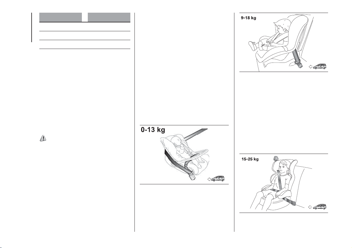
Group Weight groups
Group 1 9 - 18 kg
Group 2 15 - 25 kg
Group 3 22 - 36 kg
All restraint devices must bear the
certification data, together with the
control mark, on a label solidly fixed to
the child restraint system which must
never be removed.
Lineaccessori MOPAR
®
includes child
restraint systems for each weight
group. These devices are
recommended having been specifically
designed for Fiat vehicles.
FITTING A CHILD
RESTRAINT SYSTEM
WITH SEAT BELTS
92) 93) 94)
The Universal child restraint systems
installed with the seat belts only are
type-approved on the basis of the ECE
R44 standard and are divided into
various weight groups.
IMPORTANT The figures are indicative
and provided for assembly purposes
only. Fit the child restraint system
according to the instructions, which
must be included.
IMPORTANT Following an accident of a
certain importance, it is recommended
to replace both the child restraint
system and the seat belt to which it
was bound.
Group 0 and 0+
Babies up to 13 kg must be carried
with a rear facing child restraint system
of a type as shown in fig. 67 which,
supporting the head, does not induce
stress on the neck in the event of
sudden decelerations.
The child restraint system is secured by
the vehicle seat belts, as shown in fig.
67 and it must restrain the child in
turn with its own belts.
Group 1
Children weighing from 9 to 18 kg may
be transported in forward facing child
restraint systems fig. 68.
Group 2
Children from 15 to 25 kg may use the
vehicle seat belts directly fig. 69.
In this case, the child restraint system is
used to position the child correctly
with respect to the seat belts so that
the diagonal belt section crosses the
child’s chest and not the neck, and the
lower part is snug on the pelvis not
the abdomen.
67
F1D0055
68
F1D0056
69
F1D0057
74
SAFETY
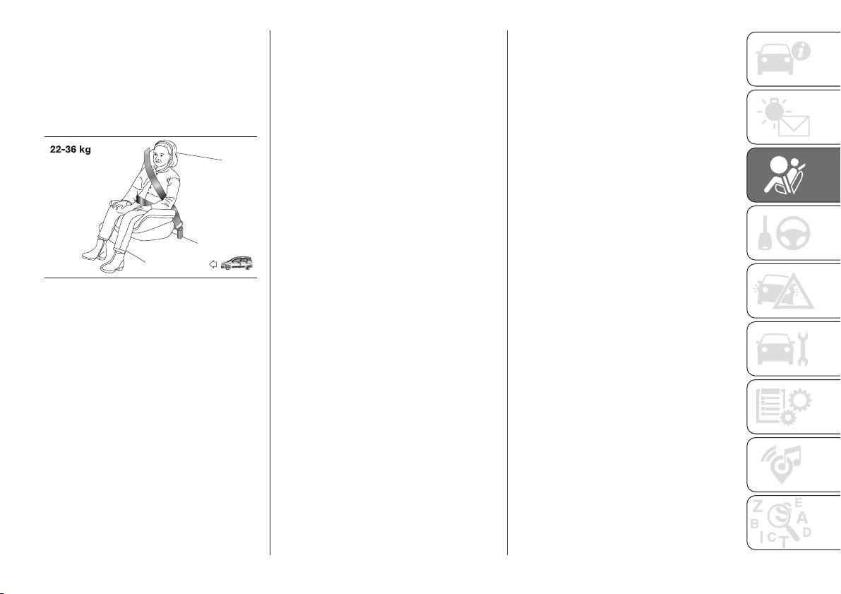
Group 3
For children between 22 kg and 36 kg,
there are boosters which allow the
seat belt to be worn correctly.
The fig. 70 shows the correct child
positioning on the rear seat.
Children over 1.50m in height can wear
seat belts like adults.
70
F1D0058
75
PASSENGER SEAT COMPLIANCE WITH REGULATIONS ON UNIVERSAL CHILD
RESTRAINT SYSTEM USE
The car complies with the new European Directive 2000/3/EC which governs the arrangement possibilities for child restraints
on the various seats of the car as shown in the following table:
Group Weight groups
Front passenger's seat(*)
Rear central
passenger (for
versions/markets,
where provided)
Rear side
passengers
Airbag enabled Airbag disabled
Group0 upto10kg
XUXU
Group 0+ up to 13 kg
XUXU
Group 1 9-18 kg
XUXU
Group 2 15-25 kg
UUXU
Group 3 22-36 kg
UUXU
X= Seat not suitable for children in this weight category
U= Suitable for child restraint systems in the "Universal" category, according to European Regulation EEC-R44 for the specified "Groups".
(*) IMPORTANT: NEVER fit a rearward-facing child seat in the front passenger seat if the airbag is active. If you wish to fit a
rearward-facing child seat in the front passenger seat, first deactivate the relative airbag (see instructions in the paragraph
(Supplementary protection system (SRS) – Airbag”)
76
SAFETY
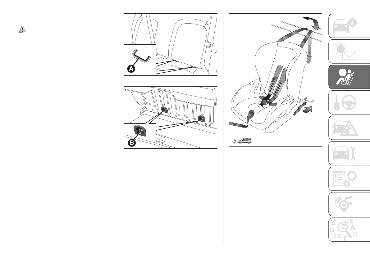
INSTALLING AN ISOFIX
CHILD CARSEAT
95) 96) 97) 98)
The outer rear seats of the vehicle are
equipped with ISOFIX anchorages,
a European standard which makes
fitting a child restraint system quick,
simple and safe.
The ISOFIX system lets you install the
ISOFIX child restraining system without
using the car seat belts but connecting
them directly to the carseat with three
anchors in the car. Traditional child
restraint systems can be fitted
alongside ISOFIX child restraint systems
on different seats in the same vehicle.
To install an ISOFIX child restraint
system, attach it to the two metal
anchorages A fig. 71 located where the
rear seat cushion meets the backrest,
then fix the upper strap (available
together with the restraint system) to
the dedicated anchorage B fig. 72
located at the bottom behind the
backrest.
As an example, fig. 73 shows an
example of a Universal ISOFIX child
restraint system for weight group 1.
IMPORTANT The fig. 73 is indicative
and for assembly purposes only. Fit the
child restraint system according to
the instructions, which must be
included.
IMPORTANT Following an accident of a
certain importance, it is recommended
to replace both the child restraint
system and the Isofix anchoring
devices.
71
F1D0060
72
F1D0061
73
F1D0059
77
SUITABILITY OF PASSENGER SEATS FOR ISOFIX CHILD RESTRAINT SYSTEM USE
The table below shows the various installation possibilities for ISOFIX child restraint systems on seats fitted with the specific
anchorages in accordance with European standard ECE 16.
Weight group
Child restraint system
position
Isofix size class Rear side Isofix positions
Group 0 up to 10 kg Rear facing E
IL (*)
Group 0+ up to 13 kg
Rear facing E
IL (*)
Rear facing D
IL (*)
Rear facing C
X
Group1from9upto18kg
Rear facing D
IL (*)
Rear facing C
X
Forward facing B
IUF-IL
Forward facing B1
IUF-IL
Forward facing A
IUF-IL
IL: suitable for ISOFIX child restraint systems specific and approved for this type of vehicle.
(*): the Isofix child restraint system can be installed by adjusting the front seat.
X: ISOFIX position not suitable for ISOFIX child restraint systems in this group of weight and/or size class.
IUF-IL: Suitable for Isofix child restraint systems to be positioned in forward facing position, universal class (fitted with third upper mounting), type-approved for the
relevant weight group.
NOTE When a Universal ISOFIX child restraint system is used, only ECE R44 "ISOFIX Universal" (R44/03 or further upgrades)
type-approved child restraint systems can be used.
The other weight groups are covered by specific ISOFIX child restraint systems, which can be used only if specifically tested for
this vehicle (see list of vehicles provided with the child restraint system).
IMPORTANT The rear central seat (for versions/markets where provided) and the passenger front seat are not approved for any
type of Isofix child restraint system.
78
SAFETY
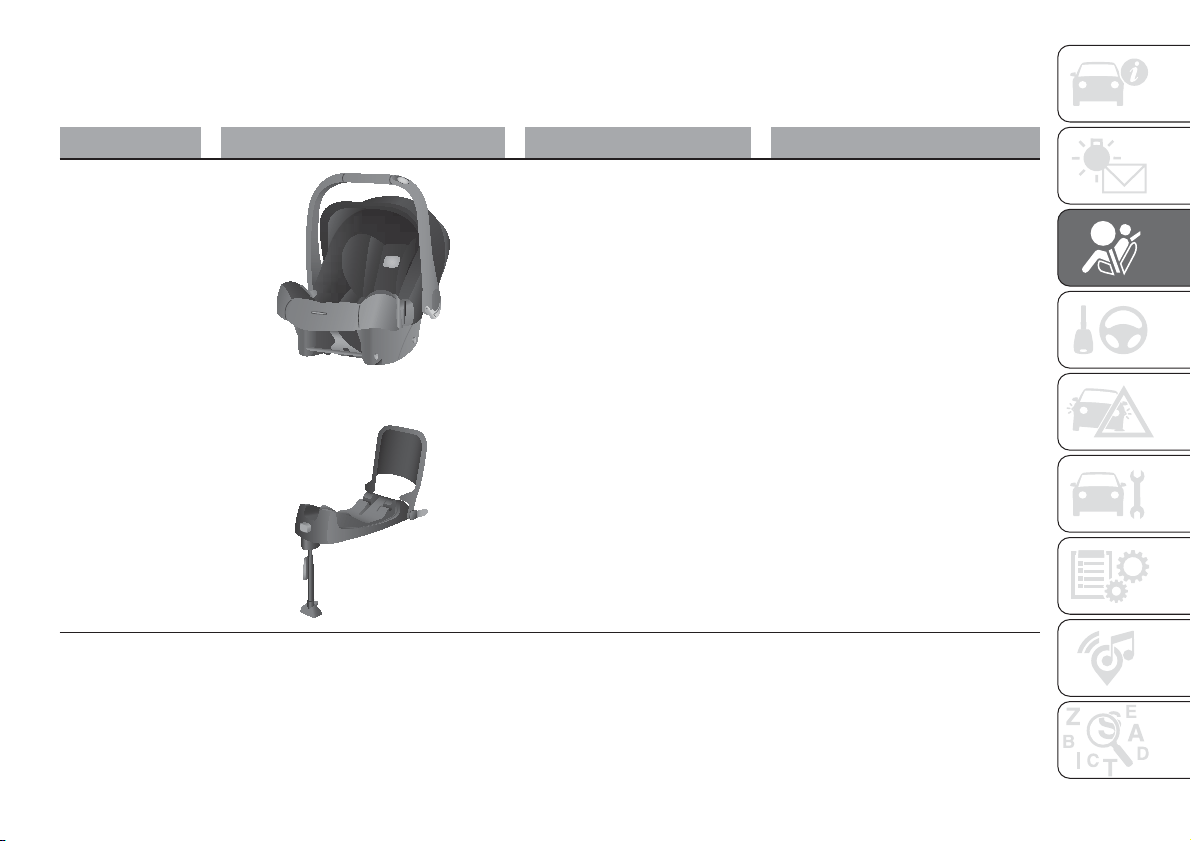
CHILD RESTRAINT SYSTEMS RECOMMENDED BY FCA FOR YOUR PANDA
Lineaccessori MOPAR
®
includes a complete range of child restraint systems to be fixed using the seat belt with three
anchorage points or the ISOFIX anchorages.
Weight group Child restraint system Type of child restraint system Child restraint system installation
Group 0+: from birth
to 13 kg
Britax Baby Safe plus
Type-approval number: E1
04301146
Fiat order code: 71806415
Universal/ISOFIX child restraint system.
It must be installed facing rearwards,
using the vehicle seat belts only, or the
dedicated ISOFIX base (which can be
purchased separately) and the vehicle
ISOFIX anchorages.
It must be fitted on the rear outer
seats.
++
Britax Baby Safe ISOFIX base
Fiat order code: 71806416
79
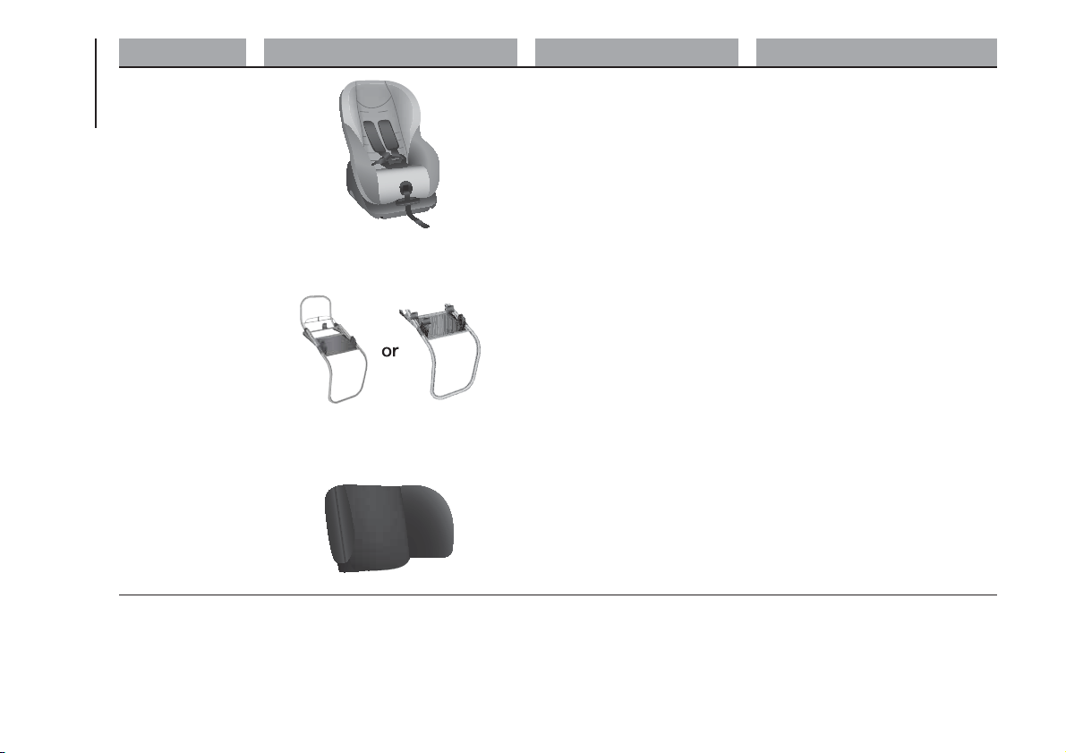
Weight group Child restraint system Type of child restraint system Child restraint system installation
Group 1: from 9 up
to 18 kg
Fair G0/1S
Type-approval number: E4
04443718
Fiat order code: 71807388
Universal/ISOFIX child restraint system.
It can be fitted forward facing/rearward
facing using only the vehicle seat belts
or the Isofix anchorages.
FCA recommends fitting it using the
rear facing ISOFIX platform (RWF
specific "A" type - to be purchased
separately) or the forward facing
ISOFIX platform (FWF specific "M" type
- to be purchased separately), the rigid
head restraint (to be purchased
separately) and the ISOFIX anchorages
for the vehicle.
It must be fitted on the rear outer
seats.
++
Fair ISOFIX RWF platform,
"A" type for G 0/1S
Fiat order code: 71805368
or
Fair ISOFIX FWF platform,
"M" type for G 0/1S
Fiat order code: 71806374
++
FAIR head restraint
Fiat order code: 71807387
80
SAFETY
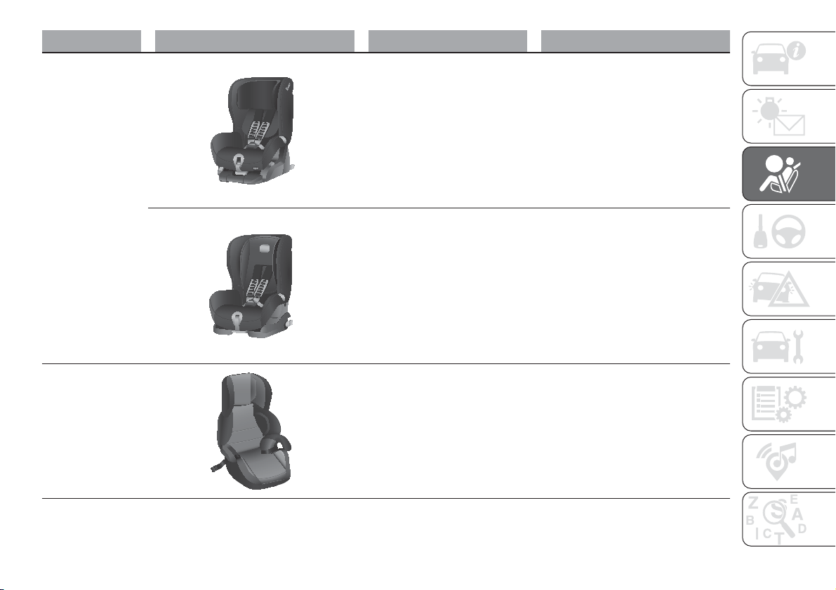
Weight group Child restraint system Type of child restraint system Child restraint system installation
Group 1: from 9 up
to 18 kg
Britax Safefix TT
Type-approval number: E1
04301199
Fiat order code: 71805956
It must be fitted facing forwards only,
using the ISOFIX attachments and the
upper strap, provided with the child
restraint system.
It must be fitted on the rear outer
seats.
Britax Roemer Duo Plus
Type-approval number: E1
04301133
Fiat order code: 71803161
It must be fitted facing forwards only,
using the ISOFIX attachments and the
upper strap, provided with the child
restraint system.
It must be fitted on the rear outer
seats.
Group 2: from 15 kg
to 36 kg
Fair Junior Fix
Type-approval number: E4
04443721
Fiat order code: 71806570
It can only be fitted facing forwards,
using the three-point seat belt and the
ISOFIX attachments of the vehicle, if
present in the selected position.
IMPORTANT FCA recommends fitting the child restraint system according to the instructions, which must be included.
81
Main recommendations to carry
children safely
Install the child restraint systems on
the rear seat, which is the most
protected position in the event of an
impact.
Keep children in rearward facing
child restraint systems for as long as
possible, until 3–4 years old if possible.
Should a rearward facing child
restraint system be installed on the rear
seats, it is advisable to position it as
far forward as the position of the front
seat allows.
If the passenger's front airbag is
deactivated, always check that the
warning light is on constantly in the
central dashboard, to make sure that
it has actually been deactivated.
Carefully follow the instructions
supplied with the child restraint system.
Keep the instructions in the vehicle
along with the other documents and
this handbook. Do not use second-
hand child restraint systems without
instructions.
Only one child is to be strapped into
each restraint system; never carry two
children using one child restraint
system.
Always check that the seat belts do
not rest on the child’s neck.
Always check that the seat belt is
well fastened by pulling on it.
While travelling, do not let the child
sit incorrectly or unfasten the belts.
Never allow a child to put the belt's
diagonal section under an arm or
behind their back.
Never carry children on your lap,
even newborns. No one can hold
a child in the case of an accident.
If the car has been involved in a
medium-high severity road accident,
replace the child restraint system with a
new one. In addition, and depending
on the type of child restraint system
installed, replace the isofix anchorages
or the seat belt with which the child
restraint system was connected.
Before installing a child restraint
system of any kind on the rear seat
facing in the direction of movement of
the vehicle, it is necessary to remove
the head restraint from the rear seat
position in which the child restraint
system is to be installed. On the other
hand, before installing a child restraint
system composed of only the seat
cushion (without backrest) on the rear
seat, it is necessary to ensure that
the head restraint of the rear seat
position in which the child restraint
system is to be installed is correctly
fitted.
WARNING
88) SEVERE DANGER When a front
passenger airbag is fitted, do not install
rearward facing child restraint systems on
the front passenger seat. Deployment of
the airbag in an accident could cause fatal
injuries to the child regardless of the
severity of the collision. It is advisable to
always carry children in a child restraint
system on the rear seat, which is the most
protected position in the event of a
collision.
89) On the sun visor there is a label with
suitable symbols reminding the user that it
is compulsory to deactivate the airbag if
a rearward facing child restraint system is
fitted. Always comply with the instructions
on the passenger side sun visor (see the
"Supplementary Restraint System (SRS)
- Airbag" paragraph).
90) Should it be necessary to carry a child
on the passenger side front seat in a rear
facing child restraint system, the passenger
side front and side airbags must be
deactivated through the display main
menu, verifying deactivation by checking
that the warning light
located in the
central part of the dashboard has switched
on. Move the passenger's seat as far
back as possible to avoid contact between
the child seat and the dashboard.
91) Do not move the front or rear seat if a
child is seated on it or on the dedicated
child restraint system.
82
SAFETY
92) Incorrect fitting of the child restraint
system may result in an inefficient
protection system. In the event of an
accident the child restraint system may
become loose and the child may be
injured, even fatally. When fitting a restraint
system for newborns or children, strictly
comply with the instructions provided
by the Manufacturer.
93) When the child restraint system is not
used, secure it with the seat belt or with
the ISOFIX anchorages, or remove it from
the vehicle. Do not leave it unsecured
inside the passenger compartment. In this
way, in the case of sudden braking or an
accident, it will not cause injuries to the
occupants.
94) After installing a child restraint system,
do not move the seat: always remove
the child restraint system before making
any adjustment.
95) Always make sure that the chest
section of the seat belt does not pass
under the arms or behind the back of the
child. In the event of an accident the seat
belt will not be able to secure the child,
with the risk of injury, including fatal injury.
Therefore the child must always wear
the seat belt correctly.
96) Do not use the same lower anchorage
to install more than one child restraint
system.
97) If a Universal ISOFIX child restraint
system is not fixed to all three anchorages,
it will not be able to protect the child
correctly. In a crash, the child could be
seriously or fatally injured.
98) Fit the child restraint system when the
car is stationary. The child restraint system
is correctly fixed to the brackets when
you hear the click. Follow the instructions
for assembly, disassembly and positioning
that the Manufacturer must supply with
the child restraint system.
SUPPLEMENTARY
RESTRAINT SYSTEM
(SRS) - AIRBAG
The car is equipped with:
driver front airbag;
front passenger airbag;
front side bags for pelvis, chest and
shoulder protection of driver and
passenger (for versions/markets, where
provided);
side bags for head protection of
front seat passengers and rear side
seat passengers (window bag).
FRONT AIRBAGS
99)
The front (driver and passenger) airbags
protect the front seat occupants in the
event of head-on crashes of medium-
high severity, by placing the cushion
between the occupant and the steering
wheel or dashboard.
Therefore non-activation of airbags in
other types of collisions (side impacts,
rear shunts, roll-overs, etc.) does not
indicate a system malfunction.
Driver and passenger front airbags are
not a replacement of but
complementary to the seat belts, which
should always be worn, as specified
by law in Europe and most non-
European countries.
83
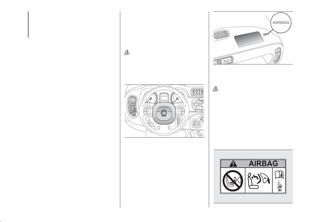
In the event of an impact, those not
wearing a seat belt are projected
forwards, and may come into contact
with the bag which is still inflating.
The protection offered by the bag is
compromised in these circumstances.
The front airbags may not activate in
the case of a frontal impact against
highly deformable objects not involving
the front surface of the car (e.g. wing
collision against guard rail) or in the
case of the car wedging under other
cars or protective barriers (e.g. under
trucks or guard rails).
Failure to activate in the conditions
described above is due to the fact that
they may not provide any additional
protection compared with seat belts, so
their activation would be inappropriate.
In these cases, non-deployment does
not indicate a system malfunction.
The driver's and passenger's
front airbags have been designed and
calibrated to protect front seat
occupants wearing seat belts.
At their maximum inflation, their volume
fills most of the space between the
steering wheel and the driver and
between the dashboard and the
passenger.
The airbags are not deployed in the
event of minor frontal impacts (for
which the restraining action of the seat
belts is sufficient). It is therefore always
necessary to wear seat belts.
Front airbag driver's side
100)
This consists of an instantly inflating
bag contained in a special
compartment in the centre of the
steering wheel fig. 74.
Passenger front airbag
This consists of an instantly inflating
bag contained in a special recess in the
dashboard fig. 75 which has a larger
volume than that of the driver.
Passenger's front airbag and child
restraint systems
101)
Rearward facing child restraint systems
must NEVER be fitted on the front
seat with an active passenger airbag
since in the event of an impact the
airbag activation may cause fatal
injuries to the transported child.
ALWAYS comply with the instructions
on the label on the passenger side
sun visor fig. 76.
74
F1D0063
75
F1D0064
76
F1D0126
84
SAFETY
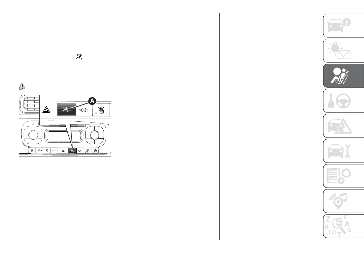
Deactivating the passenger side
airbags: front airbag and side bag
If a child must be carried on the front
seat in a rearward facing child restraint
system, deactivate the passenger
front airbag and the side bags. With
airbags deactivated, the
(A-fig.
77 warning light turns on in the
dashboard, in central position). Use the
display Setup Menu to deactivate.
102)
77
F1D0153
85
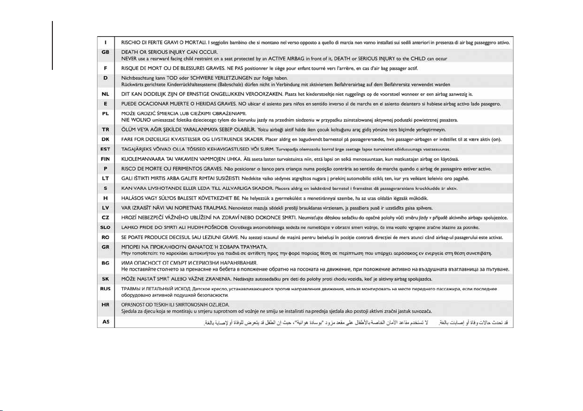
Passenger side front airbag and child restraint systems: IMPORTANT
78
F1D0127
86
SAFETY
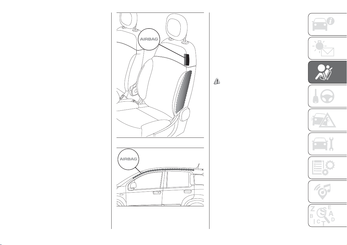
SIDE BAGS (Side bag -
Window bag)
To help increase occupants protection
in the event of a side impact, the car
is equipped with front side bags (for
versions/markets, where provided) and
window bag (for versions/markets,
where provided).
Side bags protect occupants from
side-on crashes of medium/high
severity by placing the bag between the
occupant and the internal parts of the
side structure of the vehicle.
Non-activation of side bags in other
types of collisions (front collisions, rear
shunts, roll-overs, etc.) is not a system
malfunction.
Side bags
(for versions/markets, where provided)
These comprise two types of bags
located in the front seat backrests fig.
79 which protect the pelvic, chest
and shoulder area of the occupants in
the event of a side impact of
medium-high severity.
Window bag
This consists of two "curtain" bags
housed behind the roof side lining fig.
80 and covered with trims that protect
the heads of front and rear occupants
in the event of a side impact.
The deployment of side bags in the
event of side impacts of low severity is
not required.
In the event of a side impact, the
system provides best protection if the
passenger sits on the seat in a correct
position, thus allowing correct window
bag deployment.
The window bag is not available for the
VAN version.
103) 104) 105) 106) 107) 108) 109) 110) 111) 112)
113) 114) 115)
Important notes
Do not wash the seats with water or
pressurised steam (wash by hand or at
automatic seat washing stations).
The front airbags and/or side bags may
be deployed in the event of sharp
impacts to the underbody of the car
(e.g. impact with steps, pavements,
potholes or road bumps etc.).
When the airbag deploys it emits a
small amount of dust: the dust is
harmless and does not indicate the
beginning of a fire. The dust may irritate
the skin and eyes however: in this
case, wash with neutral soap
and water.
Airbag checking, repair and
replacement must be carried out at a
Fiat Dealership.
79
F1D0066
80
F1D0067
87
If the car is scrapped, have the airbag
system deactivated at a Fiat Dealership.
Pretensioners and airbags are
deployed in different ways on the basis
of the type of collision. Failure to
activate one or more of the devices
does not indicate a system malfunction.
WARNING
99) Do not apply stickers or other objects
on the steering wheel, on the dashboard in
the passenger side airbag area, on the
side upholstery on the roof and on the
seats. Never put objects (e.g. mobile
phones) on the passenger's side
dashboard since they could interfere with
correct inflation of the airbag and also
cause serious injury to the passengers.
100) Always drive with your hands on the
rim of the steering wheel so that the airbag
can inflate freely if required. Do not drive
bent over the steering wheel, but rather sit
upright with your back firmly resting against
the seat back.
101) When there is an active passenger
airbag, DO NOT install rearward facing
child restraint systems on the front seat.
Deployment of the airbag in a crash could
cause fatal injuries to the child regardless
of the severity of the collision. Therefore,
always deactivate the passenger side
airbag when a rearward facing child
restraint system is installed on the front
passenger seat. The front passenger seat
must also be positioned back as far as
possible in order to prevent the child
restraint system from coming into contact
with the dashboard. Immediately reactivate
the passenger airbag as soon as the child
restraint system has been removed.
102) To deactivate the airbags using the
instrument panel menu, see the description
in the "Knowing the instrument panel"
chapter, "Setup Menu" paragraph.
103) Do not affix rigid objects to the
garment hooks or support handles.
104) Do not rest your head, arms or
elbows on the door, windows or the area in
which the window bag is located to avoid
possible injury during airbag inflation.
105) Never lean your head, arms or
elbows out of the window.
106) If, when the ignition device is turned
to MAR, the
warning light does not
switch on or stays on whilst driving, a fault
may have occurred in the restraint
systems. In this case the airbags or
pretensioners may not be deployed in an
impact or, in a lower number of cases, they
may be deployed accidentally. Contact a
Fiat Dealership immediately to have the
system checked.
107) In the event of “yellow”
warning
light failure, the “red” warning light
switches on and, for versions/markets
where provided, the explosive charges of
the passenger airbag and the side bags
are deactivated. When the "red" warning
light is on, before proceeding contact a Fiat
Dealership to have the system immediately
checked (see previous warning).
108) On vehicles with side bags, do not
cover the front seat backrests with extra
covers.
109) Do not travel carrying objects in your
lap, in front of your chest or between
your lips (pipe, pencils, etc.): they could
cause severe injury if the airbag is
deployed.
110) If the car has been stolen or in the
case of attempt to steal it, if it has been
subjected to vandalism or floods, have the
airbag system checked by a Fiat
Dealership.
88
SAFETY

111) The airbags may also be deployed
when the car is not moving, if the key is in
the ignition and turned to MAR-ON or
when the engine is off, if the car is hit by
another moving car. Therefore, even if the
vehicle is stationary, when an active front
passenger airbag is fitted, DO NOT install
rearward facing child restraint systems
on the front passenger seat. Deployment of
the airbag following an impact could cause
fatal injuries to the child. Therefore, always
deactivate the passenger side airbag
when a rearward facing child restraint
system is installed on the front passenger
seat. The front passenger seat must also
be positioned back as far as possible in
order to prevent the child restraint system
from coming into contact with the
dashboard. Immediately reactivate the
passenger airbag as soon as the child
restraint system has been removed. Also
remember that, if the key is turned to
STOP, none of the safety devices (airbags
or pretensioners) will be deployed in the
event of collision. Non-deployment in such
cases does not indicate a system
malfunction.
112) The airbag warning light indicates
the passenger protection status. If the
warning light is off, the passenger side
protection is activated. It can be
deactivated from the menu, in which case
the warning light comes on. When the
car is started (ignition key in MAR position),
the warning light comes on for approx. 8
seconds, provided that at least 5 seconds
have elapsed from the previous switching
off. If this does not happen please contact
a Fiat Dealership. If the car is switched
off/on again in less than 5 seconds the
warning light may remain off. In this case,
to check correct warning light operation,
switch the car off, wait at least 5 seconds
and switch on again. During the first 8
seconds, the activation of the warning light
does not actually show the passenger
protection status, but only checks its
correct operation. The warning light may
light up with various intensity levels
depending on the car conditions. The
intensity may also vary during the same key
cycle. (The warning light is tested also for
markets where the passenger protection
deactivation function is not provided,
and the warning light switches on for less
than one second when the key is turned to
MAR, then switches off again.)
113) The airbag deployment threshold is
higher than that of the pretensioners.
For collisions in the range between the two
thresholds, it is normal for only the
pretensioners to be activated.
114) The airbag does not replace seat
belts but increases their efficiency.
Because front airbags are not deployed for
low-speed crashes, side collisions,
rear-end shunts or rollovers, occupants are
protected, in addition to any side bags,
only by their seat belts, which must
therefore always be fastened.
115) If the “red”
warning light does not
switch on for a few seconds when the
key is turned to MAR, there may be a fault
with the “red” warning light. In this case,
after a few seconds, the
warning light
starts flashing. Contact a Fiat Dealership
immediately to have the system checked.
89

STARTING AND DRIVING
Let’s get to the "heart" of the vehicle:
seeing how you can exploit all of its
potential to the full.
We’ll look at how to drive it safely in any
situation, so that it can be a welcome
companion, with our comfort and
our wallets in mind.
STARTING THE ENGINE ................. 91
WHEN PARKED .............................. 92
MANUAL TRANSMISSION.............. 93
DUALOGIC TRANSMISSION........... 94
MODE SELECTOR.......................... 95
DUALDRIVE ELECTRIC POWER
STEERING ...................................... 96
ECO FUNCTION ............................. 97
START&STOP SYSTEM .................. 98
PARKING SENSORS....................... 99
REFUELLING THE VEHICLE ...........100
TOWING TRAILERS ........................103
90
STARTING AND DRIVING
STARTING THE
ENGINE
116) 117)
38) 39) 40) 41)
Before starting the engine, adjust the
seat, the interior rear view mirrors,
the door mirrors and fasten the seat
belt correctly.
Never press the accelerator pedal for
starting the engine.
VERSIONS WITH MANUAL
TRANSMISSION
Petrol versions
Proceed as follows:
engage the handbrake and put the
gear lever in neutral. For 0.9 TwinAir
and 0.9 TwinAir Turbo versions
engage the handbrake and place the
gear lever in neutral or fully press the
clutch pedal if a gear other than neutral
is engaged;
for all versions (except 0.9
TwinAir and 0.9 TwinAir Turbo) fully
depress the clutch pedal without
touching the accelerator;
turn the ignition key to AVV and
release it as soon as the engine starts.
Diesel versions
Proceed as follows:
engage the handbrake, put the gear
lever into neutral and turn the ignition
key to MAR: the warning lights
and
on the instrument panel will turn
on;
wait for the warning lights and
to turn off and then fully depress
the clutch pedal without pressing the
accelerator;
turn the ignition key to the AVV
position as soon as the warning light
turns off. Release the ignition key as
soon as the engine starts.
IMPORTANT If the engine does not
start at the first attempt, return the
ignition key to STOP before repeating
the procedure. If, with the ignition
key on MAR, the instrument panel
warning lights
and stay on (for
petrol versions only), it is advisable to
turn the key to STOP and then back to
MAR. If the
warning light remains
on, try with the other keys provided
with the car. Contact a Fiat Dealership if
you still cannot start the engine.
VERSIONS WITH
DUALOGIC
TRANSMISSION
118)
Engine starting is allowed both with a
gear engaged and with the gearbox
in neutral (N).
However, the brake pedal must always
be pressed first if neutral is not
engaged. It is therefore advisable to
place the gear lever in neutral (N) before
starting the engine.
LPG AND NATURAL
POWER VERSIONS
The engine always starts up on petrol
independently of the previously
selected mode.
42)
SWITCHING OFF THE
ENGINE
43)
Turn the ignition key to STOP while the
engine is idling.
IMPORTANT After a demanding drive,
before turning the engine off you should
allow it to idle to allow the temperature
in the engine compartment to
decrease.
91
WARNING
116) It is dangerous to run the engine in
enclosed areas. The engine consumes
oxygen and engine exhaust contains
carbon dioxide, carbon monoxide and
other toxic gasses.
117) Remember that the power brake and
electrical power steering are not
operational until the engine is started,
therefore a greater effort will be required to
press the brake pedal or turn the steering
wheel.
118) If the engine fails to start with a gear
engaged, the potentially dangerous
situation due to the fact that the gearbox is
automatically placed in neutral will be
signalled by an acoustic signal.
WARNING
38) If the warning light flashes for 60
seconds after starting or during an
extended towing period, this indicates a
problem in the glow plug preheating
system. You can use the vehicle as usual if
the engine starts but you should contact
a Fiat Dealership as soon as possible.
39) It is advisable not to demand
maximum performance from your car (e.g.
excessive acceleration, long distances at
maximum rpm, excessively intense braking,
etc.) when it is first used.
40) When the engine is switched off never
leave the key turned to MAR-ON to prevent
useless current absorption from draining
the battery.
41) Never bump start the engine by
pushing, towing or coasting downhill. This
could cause fuel to flow into the catalytic
converter and damage it beyond repair.
42) There must therefore always be some
petrol in the tank to protect the petrol
pump and to guarantee temporary
switching from LPG or Methane to petrol
operation, if high performance is required.
43) A quick burst on the accelerator
before turning off the engine serves
absolutely no practical purpose, it wastes
fuel and is especially damaging to
turbocharged engines.
WHEN PARKED
When parking and leaving the car,
proceed as follows:
engage a gear (1
st
gear if facing
uphill or reverse if facing downhill) and
leave the wheels turned;
stop the engine and engage the
handbrake;
always remove the ignition key.
Block the wheels with a wedge or a
stone if the car is parked on a steep
slope.
On versions equipped with Dualogic
transmission, wait for the letter P to be
displayed before releasing the brake
pedal.
IMPORTANT NEVER leave the car with
the gearbox in neutral (or, on versions
equipped with Dualogic transmission,
before placing the gear lever at P).
Handbrake
197) 198) 199)
The handbrake lever is located between
the front seats.
Handbrake engagement: pull lever A
fig. 81 upwards until the vehicle is
braked.
92
STARTING AND DRIVING
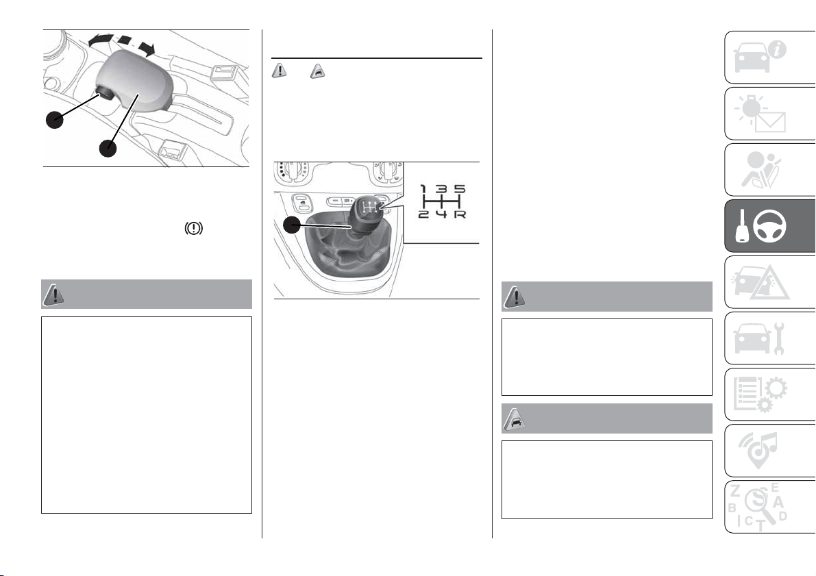
Handbrake disengagement: slightly
raise lever A and hold button B
pressed, checking that the
warning
light switches off in the instrument
panel.
WARNING
119) Never leave children unattended in
the car. Always remove the key from the
ignition when leaving the car and take
it with you.
120) The car should be braked after a few
clicks of the lever, if it is not, contact a
Fiat Dealership to have it adjusted.
121) In the case of parking manoeuvres on
roads on a gradient, the front wheels
must be steered towards the pavement
(when parking downhill), or in the opposite
direction if the vehicle is parked uphill.
Block the wheels with a wedge or a stone if
the car is parked on a steep slope.
MANUAL
TRANSMISSION
122) 44)
To engage the gears, fully depress the
clutch pedal and put the gear lever
into the required position (the diagram
is shown on the knob fig. 82).
For 0.9 TwinAir, 0.9 TwinAir Turbo and
1.2 8V 69 HP versions, to engage
reverse gear R from neutral, lift the ring
A fig. 82 located under the knob and
at the same time shift the lever to
the right and back.
For 1.3 16V MultiJet version: to engage
reverse gear R from neutral position,
move the lever to the right and then
back.
IMPORTANT Reverse can only be
engaged when the car is completely
stationary. With the engine running, wait
for at least 2 seconds with the clutch
pedal fully pressed before engaging
reverse to prevent damage to the gears
and grating.
IMPORTANT The clutch pedal should
be used only for gear changes. Do
not drive with your foot resting on the
clutch pedal, however lightly. For
versions/markets where provided, the
electronic clutch control could cut
in, interpreting the incorrect driving style
as a fault.
WARNING
122) Press the clutch pedal fully to change
gears correctly. It is therefore essential
that there is nothing under the pedals:
make sure the mats are lying flat and do
not get in the way of the pedals.
WARNING
44) Do not drive with your hand resting on
the gear lever as the force exerted, even
if slight, could lead over time to premature
wear of the gearbox internal components.
B
A
81
F1D0146
A
82
F1D0069
93
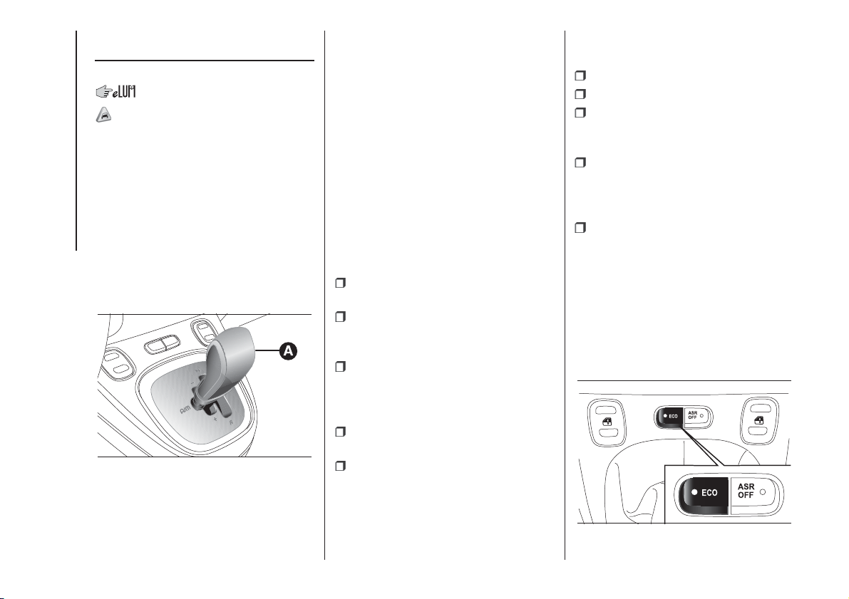
DUALOGIC
TRANSMISSION
(for versions/markets, where provided)
45)
The car may be equipped with an
electronically controlled manual
transmission known as "Dualogic"
which allows two operating logics:
MANUAL and AUTO.
GEAR LEVER
The gear lever A fig. 83, located on the
dashboard, is floating multistable type,
i.e. it has three stable positions and
three unstable positions.
The three stable positions correspond
to neutral (N), reverse (R) and the
central position located between the
unstable positions (+) and (-).
The unstable positions, in other words
those that are abandoned as soon
as the lever is released, are the
positions for requesting a higher gear
(+), requesting a lower gear (–) and
requesting automatic operating mode
(A/M).
IMPORTANT With the engine started,
any error between the lever position
and the gear actually engaged is
signalled by a buzzer until consistency
is restored.
MANUAL MODE
Proceed as follows:
press the brake pedal and start the
engine;
if AUTO appears on the display,
move the lever A fig. 83 to A/M to
select MANUAL mode;
push gear lever A towards (+) to
engage first gear (if starting from N or
R, simply place the lever in the middle
position) or R to engage reverse;
release the brake pedal and press
the accelerator pedal;
in driving conditions, push lever A of
the gearbox towards (+) to engage
the next gear up or towards (–) to
engage the next gear down.
AUTOMATIC MODE (AUTO)
Proceed as follows:
press the brake pedal;
start the engine;
if AUTO is not on the display, move
the shift lever A fig. 83 to A/M to select
AUTOMATIC mode;
push the gear lever towards (+) to
engage 1
st
gear (if starting from N or R,
simply place the lever in the middle
position) or R to engage reverse;
release the brake pedal and press
the accelerator pedal: the gear most
suited to the vehicle speed will be
engaged.
AUTO-ECO OPERATION
To activate the function, press the ECO
button fig. 84 on the central tunnel.
The ECO function can be only activated
only with automatic mode active.
83
F1D0107
84
F1D0108
94
STARTING AND DRIVING
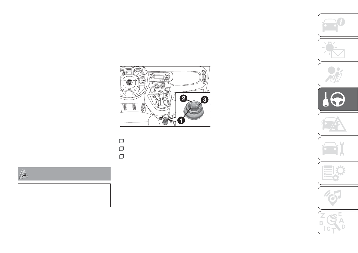
With the ECO function active, the
system will select the most suitable
gear depending on the vehicle speed,
engine rpm and intensity with which the
accelerator pedal is pressed, with the
aim of limiting fuel consumption.
“Kick Down” FUNCTION
(for versions/markets, where provided)
If necessary (e.g. when overtaking),
the system downshifts one or more
gears when the accelerator pedal
is depressed beyond the point where it
becomes stiff (and if the rpm allow it)
in order to provide suitable power and
torque for the acceleration requested
by the driver.
IMPORTANT The use of the “Kick
Down” function is recommended only
when overtaking or accelerating quickly,
in order not to increase fuel
consumption.
WARNING
45) Avoid keeping your hand on this lever
except during gear change or AUTO/
MANUAL mode requests.
MODE SELECTOR
(Panda Cross 4x4 versions)
This device allows, using the ring of the
knob fig. 85 (on the central tunnel),
three car response modes to be
selected according to driving style and
road conditions:
1 = AUTO mode;
2 = OFF ROAD mode;
3 = Gravity Control function.
The ring nut is monostable type. In
other words, it always remains in a
central position. The selected driving
mode is indicated by the corresponding
LED switching on the knob and by an
indication on the display.
"AUTO" MODE
It is a driving mode aimed at comfort
and safety in normal grip and driving
conditions.
"OFF ROAD" MODE
It is a driving mode aimed at setting off
in poor grip conditions on low-grip
road surfaces (e.g. snow, ice, mid, etc.).
Activation
Rotate the ring fig. 85 to the right and
hold in this position for half a second,
until the corresponding LED lights
up and “Off Road” mode activation
indicator appears on the display with a
dedicated message.
Once released, the ring returns to the
central position.
When the "Off Road" mode is activated,
the presetting for ELD system
intervention activates automatically.
85
F1D0116
95

IMPORTANT When the "Off Road"
mode is activated, the Start&Stop
system is temporarily disabled.
Temporary deactivation of the system
switches on the corresponding LED on
the trim (located on the central
dashboard). To activate the Start&Stop
function, with "Off Road" mode on,
press the
button on the dashboard
trim. However, when the "Off Road"
mode is deactivated, the Start&Stop
system is enabled again.
IMPORTANT When the "Off Road"
mode is activated, the City Brake
Control system is temporarily
deactivated. Temporarily deactivation of
the system results in the switching on
of the
warning light on the
instrument panel. When the "Off Road"
mode is deactivated, the City Brake
Control system is enabled again.
Turning off
To deactivate the "Off Road" mode and
return to the "Auto" mode, rotate the
ring nut to the left and hold in this
position for half a second. In this case,
the LED corresponding to “Auto” mode
will light up and the “Off Road” mode
deactivation indication will appear
on the display.
IMPORTANT If “Off Road” or “Auto”
mode was active when the engine was
stopped, the next time it is started
the mode that was selected is
reactivated.
"GRAVITY CONTROL"
FUNCTION
This driving function permits a constant
vehicle speed to be maintained
downhill.
On/Off
For engaging/disengaging the Gravity
Control function refer to the "Active
safety systems" paragraph in the
"Safety" chapter.
FAILURE OF THE MODE
SELECTOR SYSTEM
IMPORTANT In the event of system
failure or a fault with knob, no driving
modes can be selected. The display will
show a dedicated message.
IMPORTANT In this case it is not
advisable trying to drive down roads
with a steep gradient, the system
cannot help the driver in any way.
DUALDRIVE
ELECTRIC POWER
STEERING
123) 124)
This only operates with the key turned
to MAR and the engine started. The
steering allows the force required at the
steering wheel to be adjusted to suit
driving conditions.
IMPORTANT When turning the ignition
key quickly, full power steering
functionality can be achieved after a
few seconds.
CITY FUNCTION
ACTIVATION/
DEACTIVATION
Press the CITY fig. 86 button to
activate/deactivate the function. The
activation of the function is signalled by
the word CITY on the display (in some
versions it is signalled by the word CITY
appearing on the instrument panel).
When the CITY function is on, the
steering wheel effort is lighter, making
parking easier: therefore, this function is
particularly useful for driving in city
centres.
96
STARTING AND DRIVING
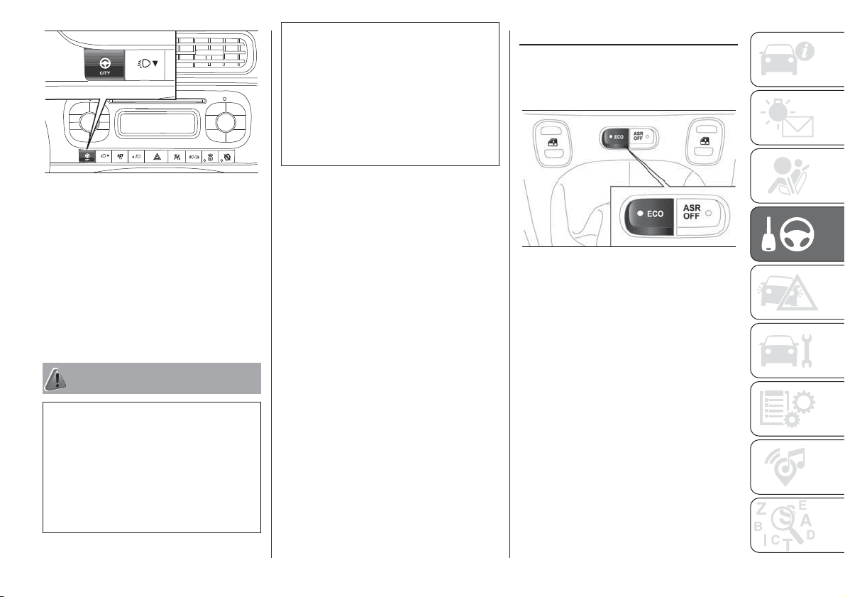
IMPORTANT During parking
manoeuvres requiring a lot of steering,
the steering may become harder; this is
normal and is due to the intervention
of the system to protect the electric
steering motor from overheating so no
intervention is required. When the
vehicle is used again later on,
the power steering will work normally.
WARNING
123) It is absolutely forbidden to carry out
any after-market operation involving
steering system or steering column
modifications (e.g. installation of anti-theft
device) that could adversely affect
performance and safety, invalidate the
warranty and also result in non-compliance
of the vehicle with type-approval
requirements.
124) Before servicing the vehicle, switch off
the engine and remove the key from the
ignition switch to activate the steering lock.
This is especially important when the
vehicle wheels are not touching the
ground. If this is not possible (for example if
the key needs to be turned to MAR or the
engine must be running), remove the
main fuse that protects the electric power
steering.
ECO FUNCTION
(for versions/markets, where provided)
To activate the function press the ECO
button fig. 87.
When the ECO function is active, the
vehicle is set for a driving style
characterised by reduced fuel
consumption. When the function is on,
the corresponding LED on the button
lights.
This function is stored, so when the
vehicle is started again, the system
keeps the setting it had before the
engine was stopped. Press the ECO
button again to deactivate the function
and restore the normal driving setting.
86
F1D0025
87
F1D0140
97
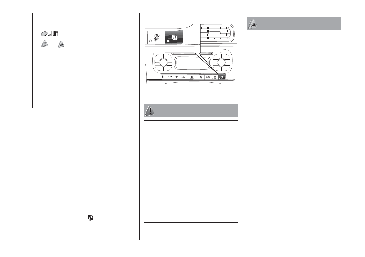
START&STOP
SYSTEM
125)
126)
The Start&Stop system automatically
stops the engine when the vehicle
is stationary and starts it again when
the driver wants to move off. This
reduces consumption, the emission of
harmful gases and noise pollution.
OPERATING MODE
Engine stopping mode: with the
vehicle stopped, the engine stops with
gearbox in neutral and clutch pedal
released.
NOTE The engine can only be stopped
automatically after exceeding a speed
of about 10 km/h, to prevent the engine
from being repeatedly stopped when
driving at walking pace.
Restarting the engine: press the
clutch pedal to restart the engine.
MANUAL SYSTEM
ACTIVATION/
DEACTIVATION
To activate/deactivate the system
manually, press the
fig. 88 button on
the dashboard control panel.
LED off: system deactivated.
LED on: system deactivated.
WARNING
125) If the battery needs to be replaced,
always contact a Fiat Dealership. Replace
the battery with one of the same type
(HEAVY DUTY) and with the same
specifications.
126) Before opening the bonnet, make
sure the engine is off and the ignition key is
in the STOP position. Please follow the
instructions on the decal near the front
crossmember. We recommend that you
remove the key from the ignition if other
people remain in the vehicle. Exit from the
vehicle only after having removed the
ignition key or having rotated it to
the STOP position. During refuelling, make
sure that the engine is off and that the
ignition key is in the STOP position.
WARNING
46) If the climate comfort is to be favoured,
the Start&Stop system can be deactivated,
for a continuous operation of the climate
control system.
88
F1D0040
98
STARTING AND DRIVING

PARKING SENSORS
127) 47)
SENSORS
The sensors are located in the rear
bumper fig. 89 and their function is to
detect the presence of any obstacles
near the rear part of the car and inform
the driver, through an intermittent
acoustic signal.
ACTIVATION/
DEACTIVATION
The sensors are automatically activated
when reverse gear is engaged. The
acoustic warning becomes more
frequent as the obstacle behind the car
gets closer.
OPERATION WITH A
TRAILER
The operation of the sensors is
automatically deactivated when the
trailer electric cable plug is inserted in
the tow hook socket of the car. The
sensors are automatically reactivated
when the trailer's cable plug is
removed.
IMPORTANT NOTES
When parking, take the utmost care
over obstacles that may be above
or under the sensor.
Objects close to the car are not
detected under certain circumstances
and could therefore cause damage
to the car or be damaged.
The following conditions may influence
the performance of the parking
assistance system:
the presence of ice, snow, mud or
multiple layers of paint on the surface of
the sensor may reduce its sensitivity
and the system performance;
mechanical interference (e.g.
washing the car, rain, strong wind, hail)
may cause the sensor to detect a
non-existent obstacle ("echo
interference");
the presence of ultrasonic systems
(e.g. pneumatic brake systems of
trucks or pneumatic drills) near the
vehicle could alter the signals sent to
the sensor;
the variation in sensor position,
caused by variation in ride (due
to suspension or shock absorber wear),
changing tyres, overloaded car, or
tuning that lowers the car, for example,
may affect parking sensor system
performance;
the presence of a tow hook without
trailer interferes with the correct
operation of the parking sensors. If a
fixed tow hook is installed, the sensors
cannot be used. If the customer installs
a removable tow hook, this must
always be disconnected from
the crossmember whenever the trailer
is not attached to prevent the activation
of the sensors.
WARNING
127) Parking manoeuvres, however, are
always the driver’s responsibility. While
carrying out these manoeuvres, always
make sure that no people (especially
children) or animals are in the area
concerned. The parking sensors are used
to assist the driver, who must never allow
his attention to lapse during potentially
dangerous manoeuvres, even those
executed at low speeds.
89
F1D0045
99

WARNING
47) For correct operation of the system,
sensors must always be clean from mud,
dirt, snow or ice. Be careful not to scratch
or damage the sensors while cleaning
them. Avoid using dry, rough or hard
cloths. The sensors must be washed using
clean water, with the addition of vehicle
shampoo if necessary. When using special
washing equipment such as high pressure
jets or steam cleaning, clean the sensors
very quickly keeping the jet more than
10 cm away.
REFUELLING THE
VEHICLE
128) 129) 130)
Always stop the engine before
refuelling.
PETROL ENGINES
Only use unleaded petrol, with an
octane number (R.O.N.) not lower than
95. In order to prevent damage to the
catalytic converter never introduce even
the smallest amount of leaded petrol,
even in the event of an emergency.
IMPORTANT An inefficient catalytic
converter leads to harmful exhaust
emissions, thus contributing to air
pollution.
IMPORTANT Never introduce leaded
petrol to the tank, even in small
amounts in an emergency, as this
would damage the catalytic converter
beyond repair.
DIESEL ENGINES
Operation at low temperatures
Only use Diesel for motor vehicles
(EN590 specification).
When using or parking the car for a
long time in the mountains or cold
areas, it is advisable to refuel using
locally available diesel fuel. In this case,
it is also advisable to keep the tank
over 50% full.
REFUELLING
PROCEDURE
48)
IMPORTANT If the filler compartment is
washed with a high-pressure jet, keep
it at a distance of at least 20 cm.
Diesel and petrol versions
The refuelling procedure described
below is illustrated on the label B fig. 90
located inside the fuel flap. The label
also indicates the fuel type (UNLEADED
FUEL=petrol, DIESEL=diesel fuel).
To refuel proceed as follows:
open flap A fig. 90, pulling it
outwards;
introduce the dispenser in the filler
and refuel;
100
STARTING AND DRIVING
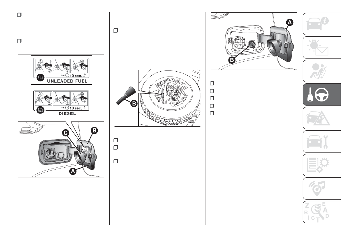
after refuelling, before removing the
dispenser, wait for at least 10 seconds
in order for the fuel to flow inside the
tank;
then remove the dispenser from the
filler and close flap A.
Flap A fig. 90 is provided with a dust
cover gaiter C which prevents deposits
of impurities and dust at the end of
the filler when the flap is closed.
Emergency refuelling
Proceed as follows:
open the boot and take the adapter
B fig. 91 located in the tool box
(versions equipped with space-saver
wheel - for versions/markets, where
provided) or in the Fix&Go container
(versions equipped with Fix&Go);
open flap A, pulling it outwards;
introduce the adapter B in the filler
and refuel;
after refuelling, remove the adapter
and close the flap, then reintroduce the
adapter in its casing and put it back
in the boot.
LPG versions
To access the LPG filler, open the
access flap A fig. 92 and undo the cap
B.
Observe the following precautions
during the refuelling operation:
switch off the engine;
apply the handbrake;
turn the ignition key to STOP;
do not smoke;
hand the special adapter A fig. 93
over to the qualified LPG refuelling
personnel.
IMPORTANT Depending on the country,
there are various types of adapters for
LPG refuelling pumps. Filler adapter,
supplied with the vehicle and located in
a special case, is specifically designed
for the country in which the vehicle is
sold. If you are in a different country,
find out what type of adaptor is used
there.
90
F1D0047
91
F1D0048
92
F1D0114
101
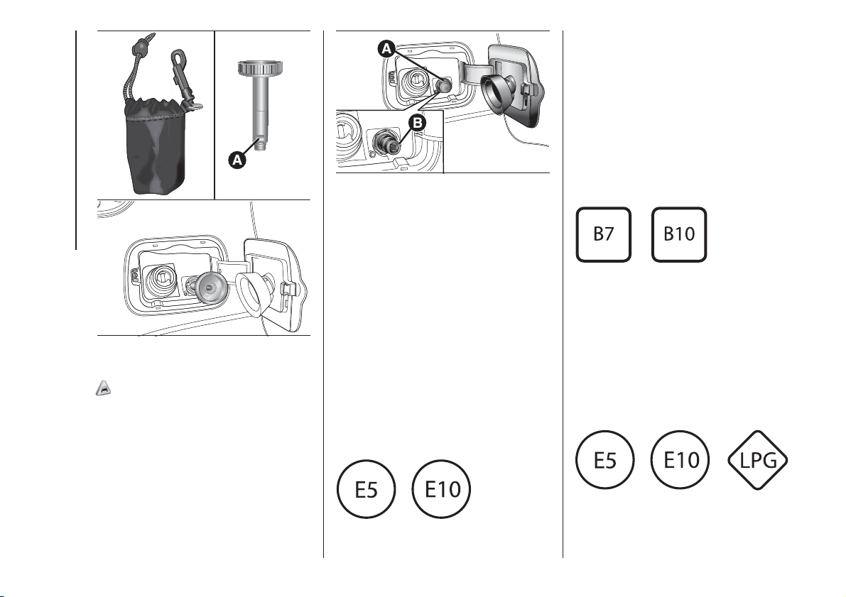
Natural Power versions
49)
To access filler B fig. 94, open the flap
and undo cap A turning it
anticlockwise.
The profile of filler B for refilling is the
universal type, compatible with Italian
and NGV1 standards. In some
European countries adapters are
considered ILLEGAL (e.g. in Germany).
Fuels - identification of
vehicle compatibility.
Graphic symbol for
consumer information in
accordance with
EN16942
The symbols shown below facilitated
recognising the correct fuel type to
be used on your car.
Before proceeding with refuelling,
check the symbols inside the fuel filler
flap (where provided) and compare
them with the symbols shown on the
fuel pump (where provided).
Symbols for petrol powered cars
E5: Unleaded petrol containing up to
2.7% (m/m) oxygen and with maximum
5.0% (V/V) ethanol compliant with
EN228.
E10: Unleaded petrol containing up to
3.7% (m/m) oxygen and with maximum
10.0% (V/V) ethanol compliant with
EN228.
Symbols for diesel powered cars
B7: Diesel containing up to 7% (V/V) of
FAME (Fatty Acid Methyl Esters)
compliant with EN590.
B10: Diesel containing up to 10% (V/V)
of FAME (Fatty Acid Methyl Esters)
compliant with EN16734.
Symbols for petrol/LPG bi-fuel cars
93
F1D0115
94
F1D0110
102
STARTING AND DRIVING
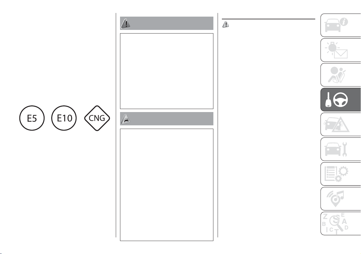
E5: Unleaded petrol containing up to
2.7% (m/m) oxygen and with maximum
5.0% (V/V) ethanol compliant with
EN228.
E10: Unleaded petrol containing up to
3.7% (m/m) oxygen and with maximum
10.0% (V/V) ethanol compliant with
EN228.
LPG: Automotive LPG compliant with
EN589.
Symbols for petrol/methane bi-fuel
cars
E5: Unleaded petrol containing up to
2.7% (m/m) oxygen and with maximum
5.0% (V/V) ethanol compliant with
EN228.
E10: Unleaded petrol containing up to
3.7% (m/m) oxygen and with maximum
10.0% (V/V) ethanol compliant with
EN228.
CNG: Automotive compressed
methane compliant with EN16723.
WARNING
128) Do not apply any object/plug to the
end of the filler which is not provided for
the car. The use of non-compliant
objects/caps could cause a pressure
increase inside the tank, resulting in
dangerous situations.
129) Do not bring naked flames or lit
cigarettes near to the fuel filler: fire risk.
Keep your face away from the fuel filler to
prevent breathing in harmful vapours.
130) Do not use a mobile phone near the
refuelling pump: risk of fire.
WARNING
48) For diesel engines, only use diesel fuel
for motor vehicles in accordance with
EN590 European specifications. The use of
other products or mixtures may damage
the engine beyond repair and
consequently invalidate the warranty, due
to the damage caused. If you accidentally
introduce other types of fuel into the tank,
do not start the engine. Empty the tank.
If the engine has been run for even an
extremely limited amount of time, you must
not only drain the fuel tank, but the rest of
the supply circuit as well.
49) The other plates (provided with the
vehicle documents) show the date when
the first cylinder inspection/test is due.
Methane refuelling stations are not
authorised to refill the cylinders when the
inspection date has expired.
TOWING TRAILERS
131) 132)
IMPORTANT
For towing motorhomes or trailers the
vehicle must be fitted with an approved
tow hook and an adequate electrical
system. Installation must be carried out
by a specialist.
Install any specific and/or additional
door mirrors as specified by the
Highway Code.
Remember that when towing a trailer,
steep hills are harder to climb, braking
distances increase and overtaking
takes longer depending on the overall
weight of the trailer.
Engage a low gear when driving
downhill, rather than constantly using
the brake.
The weight the trailer exerts on the
vehicle tow hook reduces the vehicle's
loading capacity by the same amount.
To make sure that the maximum
towable weight is not exceeded (given
in the vehicle registration document)
account should be taken of the fully
laden trailer, including accessories and
luggage.
103
Do not exceed the speed limits specific
to each country you are driving in, in
the case of vehicles towing trailers.
In any case, the top speed must not
exceed 100 km/h.
An electric brake (or electric winch)
should be supplied directly by the
battery through a cable with a cross
section of no less than 2.5 mm
2
.
In addition to the electrical branches,
the vehicle electrical system can only
be connected to the supply cable for an
electric brake and to the cable for an
internal light for the trailer, not
exceeding 15 W. For connections, use
the preset control unit with a battery
cable with section not less than 2.5
mm
2
.
On Panda Cross and Panda 4x4
versions, in the event of prolonged
vehicle use at maximum tow capacity
on slopes, replacing engine oil more
frequently (every 10,000 km) is
advisable.
IMPORTANT The use of auxiliary loads
other than external lights (electric brake,
winch, etc.) must take place with
engine running.
IMPORTANT To install a tow hook
contact a Fiat Dealership.
WARNING
131) The ABS with which the vehicle is
equipped will not control the braking
system of the trailer. Particular caution is
required on slippery roads.
132) Never modify the braking system of
the vehicle to control the trailer brake.
The trailer braking system must be fully
independent of the vehicle’s hydraulic
system.
104
STARTING AND DRIVING
IN AN EMERGENCY
A punctured tyre or a burnt-out bulb?
At times, a problem may interfere
with our journey.
The pages on emergencies can help
you to deal with critical situations
independently and with calm.
In an emergency we recommend that
you call the freephone number found in
the Warranty Booklet.
It is also possible to call the national or
international universal freephone
number to search for the nearest
Dealership.
HAZARD WARNING LIGHTS...........106
REPLACING A BULB ......................106
REPLACING FUSES........................112
REPLACING A WHEEL ...................115
FIX&GO KIT.....................................118
JUMP STARTING............................121
FUEL CUT-OFF SYSTEM ................122
TOWING THE CAR .........................123
105
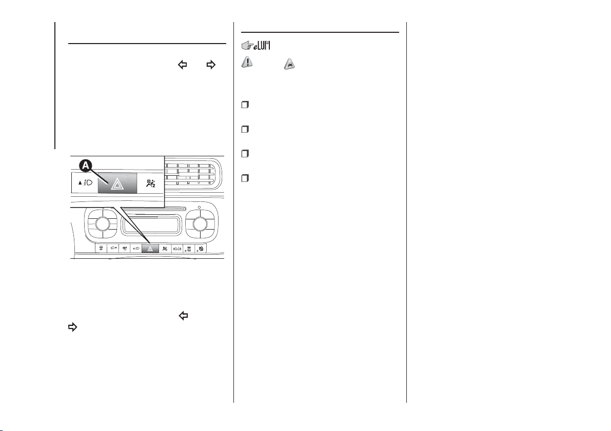
HAZARD WARNING
LIGHTS
Press button A fig. 95 to switch the
lights on/off. Warning lights
and in
the instrument panel are lit up when
the lights are ON.
IMPORTANT The use of hazard warning
lights is governed by the highway
code of the country you are driving in:
comply with legal requirements.
Emergency braking
In the event of emergency braking the
hazard warning lights switch on
automatically as well as the
and
warning lights in the instrument
panel. The lights switch off
automatically when emergency braking
ceases.
REPLACING A BULB
133) 134) 50) 51)
GENERAL
INSTRUCTIONS
Before replacing a bulb check the
contacts for oxidation;
burnt bulbs must be replaced by
others of the same type and power;
after replacing a headlight bulb,
always check its alignment;
when a light is not working, check
that the corresponding fuse is intact
before replacing a bulb. For the location
of fuses, refer to the paragraph
"Replacing fuses" in this chapter.
NOTE When the weather is cold or
damp or after heavy rain or washing,
the surface of headlights or rear lights
may steam up and/or form drops of
condensation on the inside. This is
a natural phenomenon due to the
difference in temperature and humidity
between the inside and the outside
of the glass which does not indicate a
fault and does not compromise the
normal operation of lighting devices.
The mist disappears quickly when the
lights are turned on, starting from
the centre of the diffuser, extending
progressively towards the edges.
95
F1D0023
106
IN AN EMERGENCY

Light bulbs Type Power
Dipped/main beam headlights H4 55W
Front side lights/Day lights (DRL) P21/5W 21W
Rear side lights P21/5W 5W
Front direction indicators PY21W 21W
Side direction indicators W5W 5W
Rear direction indicators PY21W 21W
Brake lights P21/5W 21W
Third brake light LED -
Fog lights H11 55W
Reversing light W16W 16W
Rear fog light W16W 16W
Number plate C5W 5W
107
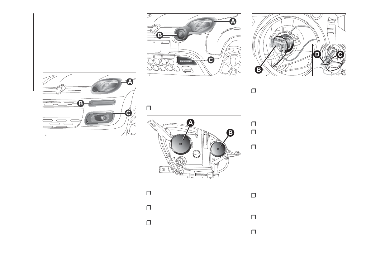
FRONT LIGHT CLUSTERS
(except Panda Cross versions)
The bulbs are arranged inside the front
light cluster fig. 96 as follows:
A - Dipped beam/main beam
headlights/direction indicators;
B - Daytime running lights (DRL);
C - Fog lights.
FRONT LIGHT CLUSTERS
(Panda Cross versions)
On the Panda Cross versions, the bulbs
are arranged inside the front light
cluster fig. 97 as follows:
A - Dipped beam/main beam
headlights/direction indicators;
B - Fog lights;
C - Daytime Running Lights (DRL).
DIPPED/MAIN BEAMS
To replace the bulb, proceed as follows:
remove cover A fig. 98;
push the connector + bulb holder
unit B fig. 99 downwards;
remove the bulb C from connector D
and replace it;
refit the new bulb on the connector
making sure that it is locked correctly,
then reinsert the connector unit and the
bulb holder B in its housing;
then refit the cover A.
DIRECTION INDICATORS
Front
To replace the bulb, proceed as follows:
remove cover B fig. 98;
turn the bulb holder anticlockwise,
extract the bulb and replace it;
refit the new bulb on the connector
making sure that it is locked correctly,
then reinsert the connector in its
housing rotating it clockwise;
Side
To replace the bulb, proceed as follows:
adjust the lens A fig. 100 to
compress in the clip B, then pull the
cluster outwards;
turn the bulb holder C anticlockwise,
extract the bulb and replace it;
refit the bulb holder C in the lens and
turn it clockwise;
96
F1D0134
97
F1D0117
98
F1D0079
99
F1D0080
108
IN AN EMERGENCY
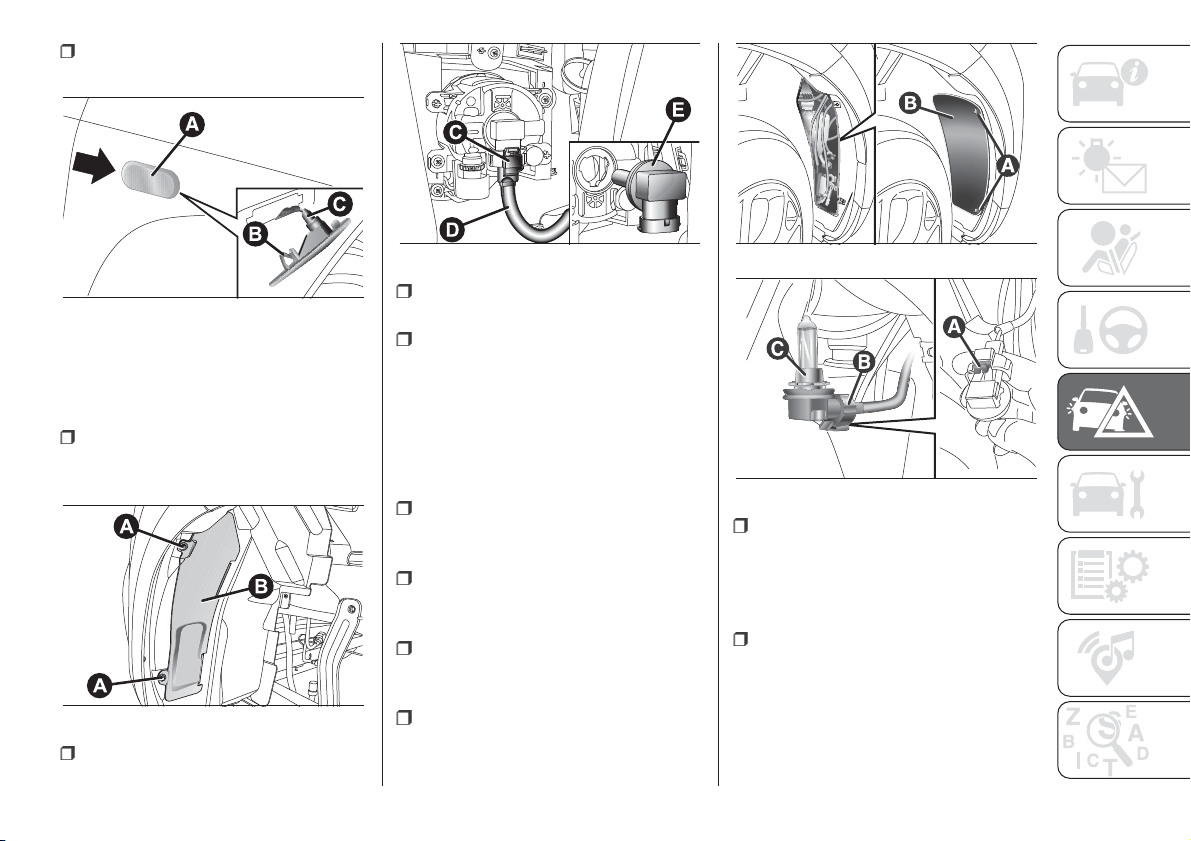
refit the cluster making sure that the
internal catch B clips into position.
FOG LIGHTS
(for versions/markets, where provided -
except Panda Cross versions)
To replace the bulb, proceed as follows:
steer the wheel completely inwards,
adjust the screws A fig. 101 and
remove the flap B;
release the clip C fig. 102 and
disconnect the electrical connector D;
rotate and remove the bulb holder E,
release and replace the bulb;
refit the new lamp and carry out the
procedure described previously in
reverse.
FOG LIGHTS
(Panda Cross versions)
To change the fog light bulb, proceed
as follows:
steer both the wheels completely,
loosen the screws A fig. 103 and
remove the guard flap B;
locate the fog light unit, rotate it
anticlockwise by a quarter of a turn and
remove it;
lift the lever A fig. 104 and
disconnect the connector B from the
bulb-bulb holder assembly C;
replace the bulb-bulb holder
assembly C;
reconnect the assembly to
connector B, reposition assembly C in
its housing by rotating it clockwise
by a quarter of a turn, until it clicks into
the correct position;
reposition the guard door B fig. 103,
taking care that the tabs are positioned
in their housings and tighten the fixing
screws A.
100
F1D0081
101
F1D0082
102
F1D0083
103
F1D0118
104
F1D0119
109
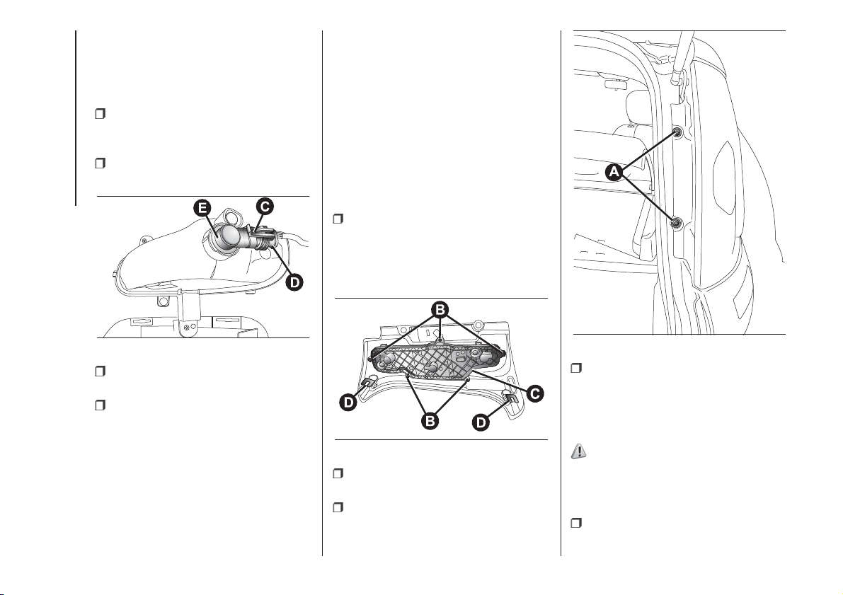
SIDE LIGHTS / DAYTIME
RUNNING LIGHTS (DRL)
(for versions/markets, where provided -
except Panda Cross versions)
To replace the bulb, proceed as follows:
steer the wheel completely, adjust
the screws A fig. 101 and remove
the flap B;
release the clip C fig. 105 and
disconnect the electrical connector D;
rotate and remove the bulb holder E,
release and replace the bulb;
refit the new lamp and carry out the
procedure described previously in
reverse.
DAYTIME RUNNING
LIGHTS (DRL)
(Panda Cross versions)
IMPORTANT To change LED DRLs
contact a Fiat Dealership.
REAR LIGHT CLUSTERS
These contain the bulbs for the side
lights, brake lights and direction
indicators.
To replace the bulb proceed as follows:
undo the two screws A fig. 106
from their seats, pull gently outwards
until releasing the whole headlight from
the two clips (press-fitted D fig. 107)
and release the connector;
undo the five screws B from their
seats and remove the bulb holder C;
remove the bulbs, pushing them
slightly and turning them anti-
clockwise;
refit the new lamp and carry out the
procedure described previously in
reverse.
REVERSING LIGHT/REAR
FOG LIGHT
135)
The reversing lights and rear fog lights
are located in the rear bumper.
To replace the bulb, proceed as follows:
adjust the tabs A and remove the
flap B fig. 108
105
F1D0084
107
F1D0086
106
F1D0085
110
IN AN EMERGENCY
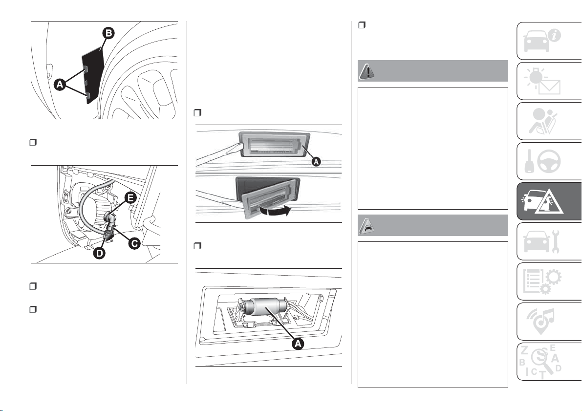
release the clip C fig. 109 and
disconnect the electrical connector D;
turn the bulb holder E and remove it,
extract the bulb and replace it;
refit the new lamp and carry out the
procedure described previously in
reverse.
THIRD BRAKE LIGHTS
These are located in the tailgate and
are LED lights. For replacement,
contact a Fiat Dealership.
NUMBER PLATE LIGHTS
To replace the bulbs, proceed as
follows:
remove lens A fig. 110;
replace the bulb A fig. 111, releasing
it from the side contacts;
Insert the new bulb and make sure
that it is correctly clamped between the
contacts, then refit the lens A fig. 111.
WARNING
133) Modifications or repairs to the electric
system that are not carried out properly
or do not take the system technical
specifications into account can cause
malfunctions leading to the risk of fire.
134) Halogen bulbs contain pressurised
gas, in the case of breakage they may
burst causing glass fragments to be
projected outwards.
135) Before replacing the bulb, wait for the
catalytic converter to cool down: RISK
OF BURNS.
WARNING
50) Halogen bulbs must be handled
holding the metal part only. Touching the
transparent part of the bulb with your
fingers may reduce the intensity of the
emitted light and even reduce the lifespan
of the bulb. In the event of accidental
contact, wipe the bulb with a cloth
moistened with alcohol and let the bulb
dry.
51) Where possible, it is advisable to have
bulbs changed at a Fiat Dealership. The
correct operation and direction of the
external lights are absolutely essential for
the safety of the car and of compliance
with the law.
108
F1D0087
109
F1D0088
110
F1D0089
111
F1D0090
111
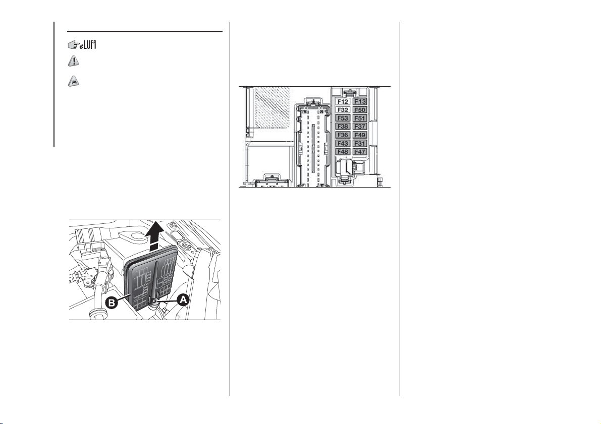
REPLACING FUSES
136) 137) 138) 139) 140) 141)
52)
GENERAL INFORMATION
To facilitate fuse replacement, use the
pliers hooked inside the fuse box lid on
the dashboard left-hand side.
ENGINE COMPARTMENT
FUSEBOX
The fusebox is located next to the
battery: to access the fuses, undo
screw A fig. 112, and lift cover B
upwards.
The number identifying the electrical
component corresponding to each fuse
is shown on the cover. After replacing
the fuse, make sure you close cover
B on the junction unit.
DASHBOARD FUSEBOX
The fuse box fig. 113 is located near
the left side of the steering column and
the fuses can be accessed easily from
the lower part of the dashboard.
112
F1D0091
113
F1D0093
112
IN AN EMERGENCY
ENGINE COMPARTMENT FUSEBOX
fig. 112
USERS FUSE AMPERE
Body Computer node F01 60
Passenger compartment fan F08 40
Front fog lights F09 15
Horns F10 15
Main beam headlights F14 15
Heated windscreen F15 70
Air conditioning compressor F19 7.5
Front power socket (with or without cigar lighter) F20 15
Fuel pump F21 15
Blow-by F30 5
+15
(*) reversing lights
F87 5
Mirror demisting F88 7.5
Heated rear window F89 30
Battery charge status sensor F90 5
(*)+15 = ignition-operated positive pole
113

DASHBOARD FUSEBOX
fig. 113
USERS FUSE AMPERE
+15 (*) headlight alignment corrector
F13 5
+15
(*) Ignition-operated control with inhibition during
engine starting
F31 5
+30
(**)
F36 10
+15
(*) brake pedal switch (NO)
F37 7.5
Central door locking F38 20
Two-way windscreen washer pump F43 20
Front electric window (driver side) F47 20
Front electric window (passenger side) F48 20
+15
(*)
F49 7.5
+15
(*)
F50 7.5
+15
(*)
F51 5
+30
(**)
F53 7.5
(*)+15 = ignition-operated positive pole
(**)+30 = battery direct positive pole (not ignition-operated)
114
IN AN EMERGENCY
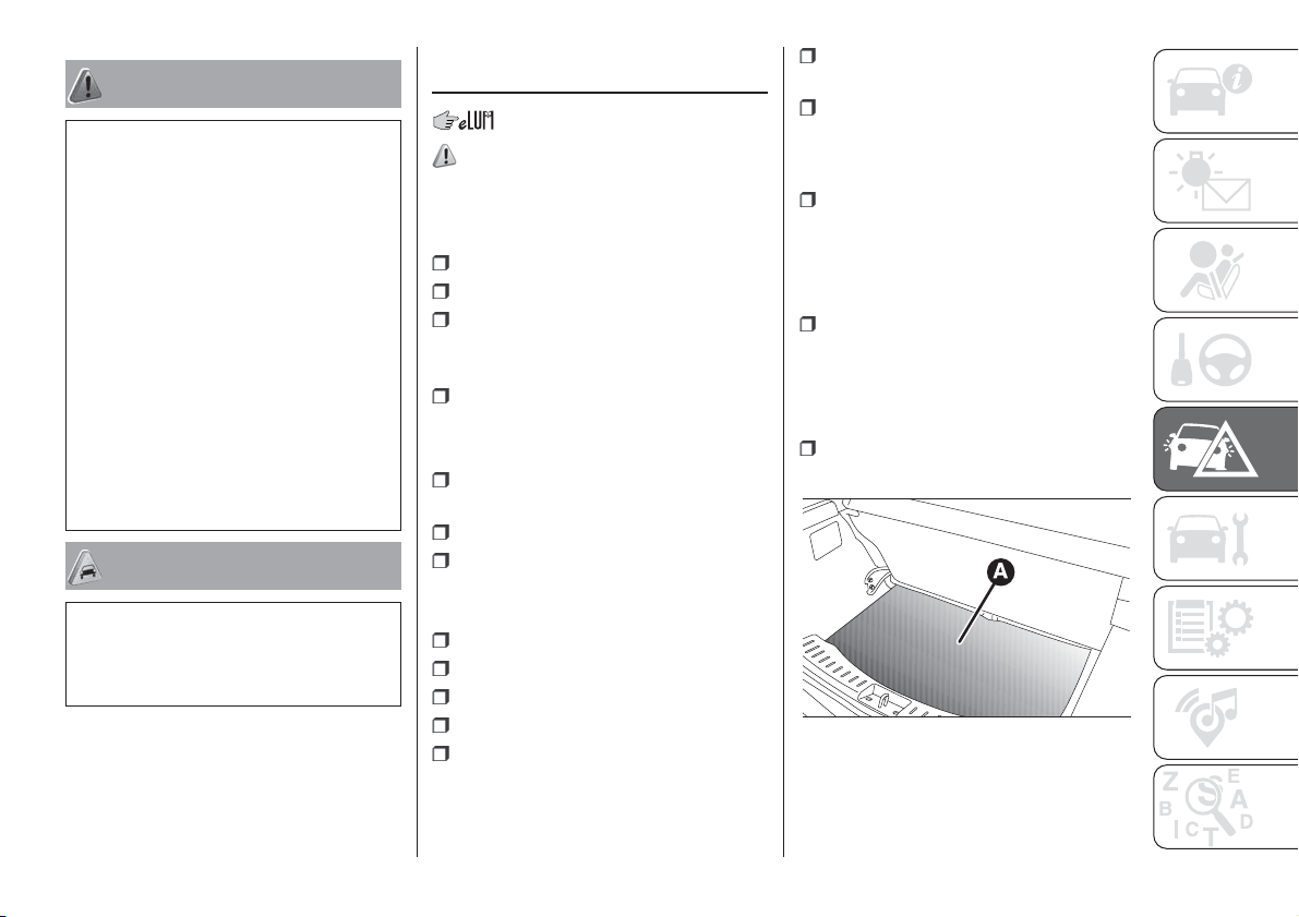
WARNING
136) If the replaced fuse blows again,
contact a Fiat Dealership.
137) Never replace a fuse with metal wires
or other material.
138) Never replace a fuse with another
with a higher amp rating; DANGER OF
FIRE.
139) If a general fuse (MEGA-FUSE,
MIDI-FUSE, MAXI-FUSE) blows contact a
Fiat Dealership.
140) Before replacing a fuse, make sure
that the ignition key has been removed and
that all the other services are switched off
and/or disengaged.
141) Contact Fiat Dealership if a safety
system (airbags, brakes), engine system
(engine, gearbox) or steering system
general protection fuse blows.
WARNING
52) If you need to wash the engine
compartment, take care not to directly hit
the fuse box and the window wiper motors
with the water jet.
REPLACING A
WHEEL
142) 143) 144) 145) 146)
JACK
Please note that:
the jack weight is 1.76 kg;
the jack requires no adjustment;
the jack cannot be repaired and in
the event of a fault it must be replaced
by another genuine one;
no tool other than its cranking
device may be fitted on the jack.
Jack maintenance
prevent any dirt from depositing on
the "worm screw";
keep the "worm screw" lubricated;
never modify the jack.
Conditions in which not to use the
jack
temperature below -40°C
on sandy or muddy ground
on uneven ground
on steep roads
in extreme weather conditions:
thunderstorms, typhoons, hurricanes,
blizzards, storms, etc.
in direct contact with the engine or
to carry out repairs under the vehicle
on boats.
CHANGING PROCEDURE
Proceed as follows:
stop the car in a position that is not
dangerous for oncoming traffic where
you can change the wheel safely. The
ground must be flat and sufficiently
compact;
switch off the engine, pull up the
handbrake and engage the 1
st
gear or
reverse. Wear the reflective safety
jacket (compulsory by law) before
getting out of the car;
open the boot and lift up the mat A
fig. 114;
114
F1D0723
115
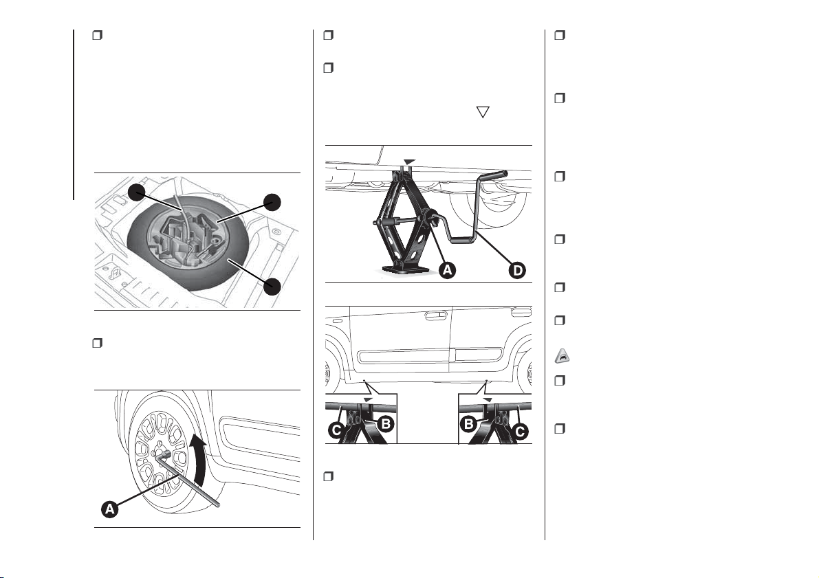
using the wrench A fig. 115 located
in the tool box, loosen the locking
device, take the tool box B and place it
close to the wheel to be replaced.
Then take the space-saver wheel C.
For the Panda VAN and Panda 4x4
versions, the jack and the tools can be
located under the passenger side
front seat;
take the wrench A fig. 116 and
loosen the fixing bolts by about one
turn;
position the jack under the car, near
the wheel to be changed;
operate the device A fig. 117 to
extend the jack until the top of the jack
B fig. 118 fits correctly into the side
member C (next to the mark
on the
side member);
alert any bystander that the car is
about to be raised; all persons should
be kept away from the car and nobody
must touch it until it has been lowered;
fit handle D fig. 117 into the housing
in device A, operate the jack and raise
the vehicle until the wheel is a few
centimetres from the ground;
remove the wheel cap after
loosening the 3 fixing bolts and finally
loosen the fourth bolt and extract
the wheel (only for versions with wheel
caps fixed by bolts);
make sure the contact surfaces
between space-saver spare wheel and
hub are clean so that the fastening
bolts will not come loose;
fit the space-saver wheel by
inserting the first bolt for two threads
into the hole closest to the valve;
take the wrench A fig. 116 and fully
tighten the fixing bolts;
operate the jack handle D fig. 117 to
lower the car. Then extract the jack;
53)
use the wrench A fig. 116 to fully
tighten the bolts, passing alternately
from one bolt to the opposite one;
when replacing a wheel with alloy
rim it is advisable to place it upside
down, with the aesthetic part facing
upwards.
A
B
C
115
F1D0073
116
F1D0074
117
F1D0075
118
F1D0076
116
IN AN EMERGENCY
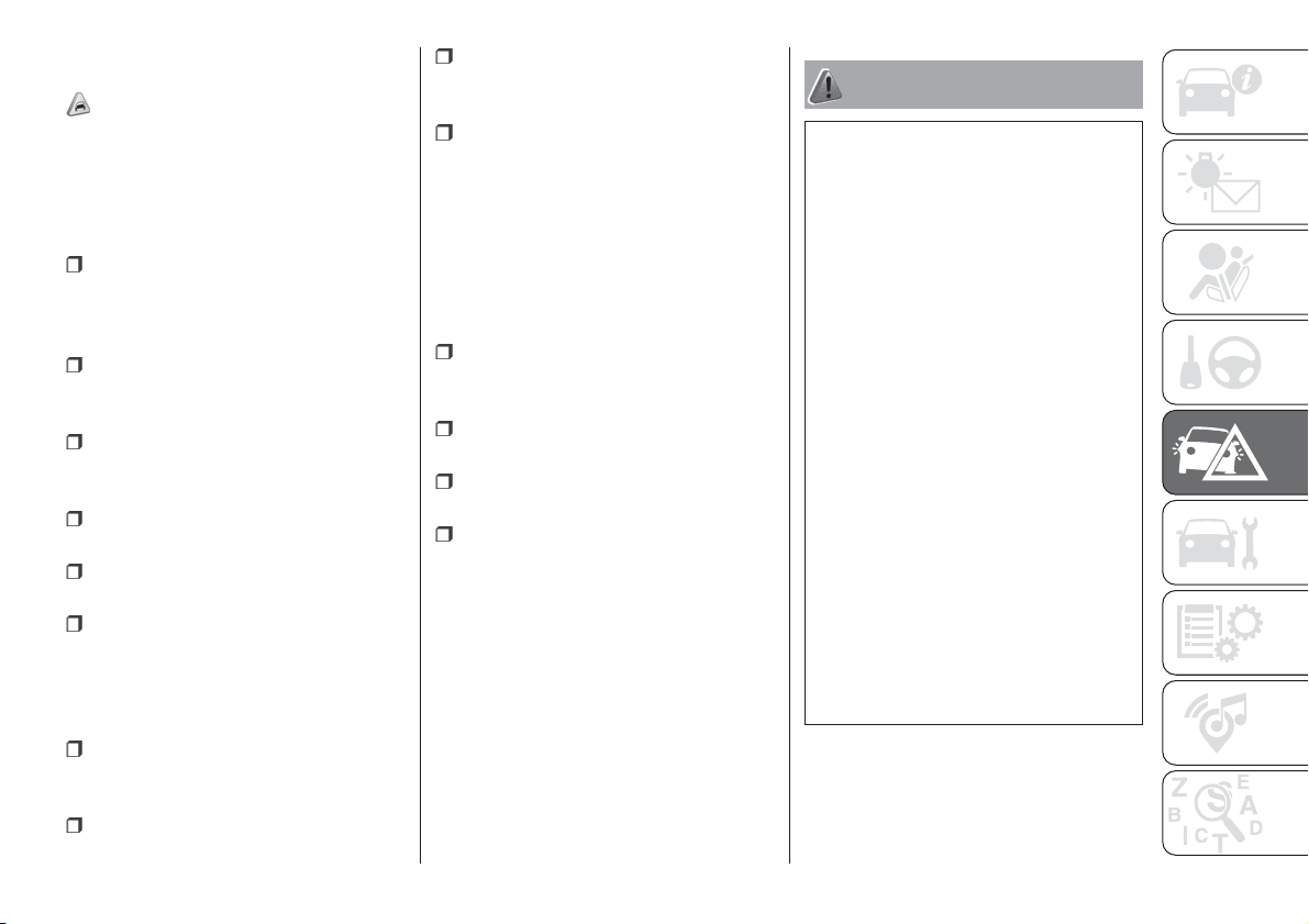
REFITTING THE
STANDARD WHEEL
54)
Following the procedure described
previously, raise the vehicle and remove
the space-saver wheel.
Versions with steel wheels
Proceed as follows:
make sure the contact surfaces
between standard wheel and hub are
clean so that the fastening bolts will not
come loose;
fit the standard wheel by inserting
the first bolt by 2 threads into the hole
closest to the inflation valve;
fit the hub cap, aligning the crescent
hole with the bolt already fitted, then
fit the other bolts;
using the wrench provided, tighten
the fastening bolts;
lower the vehicle and remove the
jack;
use the wrench provided to fully
tighten the bolts, passing alternately
from one bolt to the opposite one.
Versions with alloy rims
Proceed as follows:
insert the wheel on the hub and use
the spanner provided to tighten the
bolts;
lower the vehicle and remove the
jack;
use the wrench provided to fully
tighten the bolts, passing alternately
from one bolt to the opposite one;
reinsert the press-fitted hub cap,
making sure that the reference hole on
the wheel is aligned with the reference
pin on the cap.
NOTE If it is not fitted correctly, the hub
cap may detach when the vehicle is
running.
At the end of the operation
stow the space-saver wheel in the
compartment provided in the luggage
compartment;
insert the jack and the other tools in
the container;
arrange the container and tools on
the space-saver wheel;
correctly reposition the luggage
compartment mat.
WARNING
142) The space-saver wheel (for
versions/markets where provided) is
specific to your car, do not use it on other
models, or use the space-saver wheel
of other models on your car. The
space-saver wheel must only be used in
the event of an emergency. Never use it for
more than strictly necessary and never
exceed 80 km/h. On the space-saver
wheel there is an orange label,
summarising the main warnings regarding
space-saver wheel usage restrictions.
Never remove or cover the label. The label
contains the following indications in four
languages: "Warning! For temporary use
only! 80 km/h max! Replace with standard
wheel as soon as possible. Never cover
this indication." Never apply a wheel cap
on a space-saver wheel.
143) Alert other drivers that the car is
stationary in compliance with local
regulations: hazard warning lights, warning
triangle, etc. Any passengers on board
should leave the car, especially if it is
heavily laden. Passengers should stay
away from on-coming traffic while the
wheel is being changed. On hills or uneven
roads, use chocks or appropriate objects
to block the wheels of the vehicle.
117
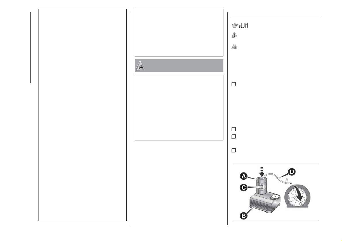
144) The vehicle's driving characteristics
will be modified with the space-saver wheel
fitted. Avoid violent acceleration and
braking, abrupt steering and fast cornering.
The overall duration of the space-saver
wheel is about 3000 km, after which the
relevant tyre must be replaced with another
one of the same type. Never install a
traditional tyre on a rim designed to be
used as a space-saver wheel. Have the
wheel repaired and refitted as soon as
possible. Using two or more space-saver
wheels at the same time is forbidden.
Do not apply grease to the bolt threads
before fitting: they could come unscrewed.
145) The jack is a tool developed and
designed only for changing a wheel, if a
tyre gets punctured or damaged, on the
vehicle with which it is supplied or on other
vehicles of the same model. Any other
use, e.g. to jack up other vehicle models or
different things, is strictly prohibited. Never
use for maintenance or repair activities
under the car or to exchange the
summer/winter wheels and vice versa.
Never go under the raised vehicle. If any
work under the vehicle is necessary,
contact the Fiat Service Network. Incorrect
positioning of the jack may cause the
raised vehicle to fall: use only in the
positions indicated. Do not use the jack for
loads higher than the one shown on its
label. Never start the engine with vehicle
raised. If the vehicle is raised more than
necessary, everything can become more
unstable, with the risk of the vehicle
dropping violently. Thus, lift the vehicle only
as needed in order to access the spare
wheel.
146) If the hub cap is not fitted correctly, it
may come off when the car is travelling.
Never tamper with the inflation valve. Never
introduce tools of any kind between rim
and tyre. Check tyre and space-saver
wheel pressures regularly, complying with
the values given in the "Technical
specifications" chapter.
WARNING
53) When turning the jack handle make
sure that it can turn freely without scraping
your hand against the ground. The moving
components of the jack ("worm screw"
and joints) can also cause injuries: avoid
touching them. If you come into contact
with lubricating grease, clean yourself
thoroughly.
54) Contact a Fiat Dealership as soon as
possible to have the correct tightening
of the wheel bolts checked.
Fix&Go KIT
147) 148)
55)
DESCRIPTION
The Fix&Go quick tyre repair kit fig. 119
is located in the boot, inside a
dedicated container and consists of:
one cartridge A containing sealant
and fitted with: transparent tube for
injecting the sealant D and sticker
C with the wording “Max 80 km/h” to
be placed in a clearly visible position
(e.g. on the dashboard) after repairing
the tyre;
one compressor B;
one leaflet containing instructions for
using the kit;
a pair of gloves located in the hose
compartment of the cartridge D.
119
F1D0709
118
IN AN EMERGENCY
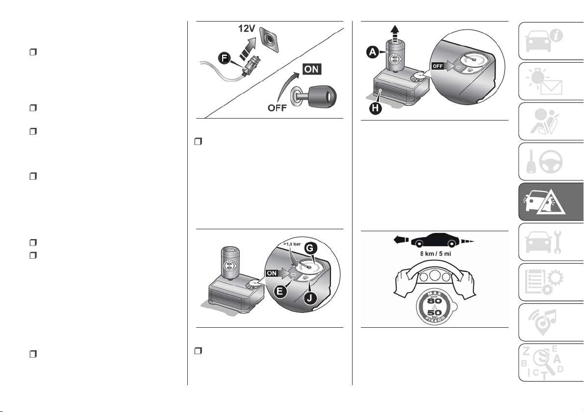
REPAIR PROCEDURE
Proceed as follows:
stop the car in a position that is not
dangerous for oncoming traffic where
you can carry out the procedure safely.
The ground must be flat and sufficiently
compact;
stop the engine, engage the hazard
warning lights and the parking brake;
wear the reflective safety jacket
before getting out of the car (anyway
comply with the laws in force in the
country you are driving in);
insert the cartridge A containing the
sealant in the proper compartment of
the compressor B, pressing it down
hard fig. 119. Remove the adhesive
speed label C and apply it in a visible
position (fig. 123);
wear the gloves;
remove the cap from the tyre valve
and connect and screw the transparent
tube of the sealing fluid D fig. 119
onto the valve. If a 250 ml cartridge is
present the housing of the transparent
tube is provided with removable ring
to facilitate extraction. Make sure that
the ON-OFF button E fig. 121 is in
the off position (button not pressed);
plug the electric connector F fig. 120
into the 12V socket of the vehicle and
start the vehicle engine;
operate the compressor by pressing
the ON-OFF button E fig. 121. When
the pressure shown in the "Wheels"
paragraph in the “Technical data”
chapter or on the specific label appears
on the pressure gauge G, stop the
compressor by pressing the ON-OFF
button E again;
disconnect the cartridge A from the
compressor, by pressing the release
button H and lifting the cartridge A
upwards fig. 122.
If the pressure gauge G fig. 121
indicates a pressure lower than 1.8 bar
/ 26 psi 15 minutes after starting the
compressor, switch off the compressor,
disconnect the sealing fluid tube D
from the tyre valve and remove the
cartridge A from the compressor fig.
122.
120
F1D0710
121
F1D0711
122
F1D0712
123
F1D0713
119
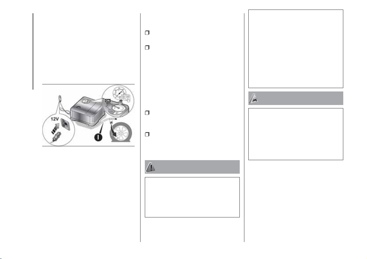
Move the vehicle by approximately 10
m to promote the distribution of
sealant; stop the vehicle safely, operate
the handbrake and restore pressure
using the black inflation pipe I fig. 124
to reach the required pressure. If also in
this case, the pressure is lower than
1.8 bar / 26 psi 15 minutes after turning
on, do not resume driving but contact
a Fiat Dealership.
After driving for about 8 km / 5 miles,
position the car in a safe and suitable
area and engage the handbrake. Take
the compressor and restore pressure
using the black inflation tube I fig. 124.
If the pressure shown is higher than
1.8 bar / 26 psi, restore the pressure
and drive safely to a Fiat Dealership as
soon as possible. If, however, the
pressure is lower than 1.8 bar / 26 psi,
do not resume driving but contact a
Fiat Dealership.
INFLATION PROCEDURE
Proceed as follows:
stop the vehicle safely, as shown
above, and operate the handbrake;
extract the black inflation tube I fig.
124 and screw it firmly onto the tyre
valve. Follow the instructions shown in
fig. 120 and fig. 124.
Press the air release button J fig. 121 to
adjust any tyre overpressure.
CARTRIDGE
REPLACEMENT
Proceed as follows:
only use original Fix&Go cartridges,
which can be purchased from the
Fiat Dealership.
to remove the cartridge A fig. 119
press the release button H fig. 122 and
lift it.
WARNING
147) The information required by the
applicable regulation is indicated on the
Fix&Go kit package label. Carefully read
the label on the cartridge before use, avoid
improper use. The kit should be used by
adults and cannot be used by children.
148) IMPORTANT: Do not exceed 80 km/h.
Avoid sudden acceleration or braking.
The kit provides a temporary repair,
therefore the tyre must be examined and
repaired by a specialist as soon as
possible. Before using the kit, ensure that
the tyre is not excessively damaged and
that the rim is in good condition, otherwise
do not use it and call roadside assistance.
Do not remove foreign bodies from the
tyre. Do not let the compressor turned on
for more than 20 consecutive minutes -
overheating hazard.
WARNING
55) The sealant is effective with external
temperatures of between -40°C and
+55°C. The sealant has an expiry date. It is
possible to repair tyres which have been
damaged on tread up to a diameter of
6 mm. Show the cartridge and the label to
the personnel charged with handling the
tyre treated with the tyre repair kit.
124
F1D0714
120
IN AN EMERGENCY
JUMP STARTING
If the battery is flat, a jump starting can
be performed using the battery and
the cables of another vehicle, or using a
booster battery.
If the warning light
remains on
continuously on the instrument panel,
contact the Fiat Dealership immediately.
IMPORTANT NOTES
When a booster battery is used, comply
with the utilisation and precaution
instructions specified by the producer.
Do not use the booster battery or
any other source of external supply with
a voltage above 12 V: the battery, the
starter, the alternator and the electrical
system of the vehicle could be
damaged.
Do not attempt jump starting if the
battery is frozen. The battery could
break and explode!
PREPARATION TO JUMP
STARTING
149) 150)
56) 57)
IMPORTANT The positive terminal (+) of
the battery is shielded by a protective
cover. Lift the cover to access the
positive terminal.
Proceed as follows:
engage the handbrake, move the
Dualogic gear lever to P (Park) or,
for versions with manual gearbox, to
neutral and bring the ignition key to
STOP;
switch off all the other electrical
devices in the car;
if another vehicle is ready for jump
starting, park the vehicle within the
reach of the cables to be used for
starting, operate the handbrake and
make sure that the ignition is
deactivated.
IMPORTANT Avoid contact between
the two vehicles since this could cause
a connection to earth and may result
in serious injury to any people nearby.
PROCEDURE FOR JUMP
STARTING
IMPORTANT If the procedure below is
carried out incorrectly, it can cause
severe injury to people or damage the
recharging system of one or both
vehicles. Carefully follow the
instructions given below.
Cable connection
Proceed as follows to carry out a jump
starting:
connect one end of the cable used
for positive (+) to the positive terminal
(+) of the car with flat battery;
connect the other end of the cable
used for positive (+) to the positive
terminal (+) of the auxiliary battery;
connect one end of the cable used
for negative (–) to the negative terminal
(–) of the auxiliary battery;
connect the other end of the cable
used for negative (–) to an engine earth
(the visible metal part of the car engine
with flat battery) far from the battery
and the fuel injection system;
start the vehicle engine with the
auxiliary battery, let it run for a few
minutes at idling. Start the engine of the
car with flat battery.
121
Cable disconnection
Once the engine has been started,
remove the cables proceeding as
follows:
disconnect the end of the cable
used for negative (–) from the engine
earth of the car with flat battery;
disconnect the other end of the
cable used for negative (–) from the
negative terminal (–) of the auxiliary
battery;
disconnect the end of the cable
used for positive (+) from the positive
terminal (+) of the auxiliary battery;
disconnect one end of the cable
used for positive (+) from the positive
terminal (+) of the car with flat battery.
If it is often necessary to perform a
jump starting, have the car battery and
the recharging system checked by a
Fiat Dealership.
IMPORTANT Any accessories (e.g.
mobile phones, etc.) connected to the
vehicle power sockets draw current
even if they are not used. These
devices, if left connected too much time
with engine off, may cause the battery
to drain with following reduction of
its life and/or failure to start the engine.
WARNING
149) This starting procedure must be
performed by expert personnel because
incorrect actions could cause electrical
discharge of considerable intensity.
Furthermore, battery fluid is poisonous and
corrosive: avoid contact with skin and
eyes. Keep naked flames and lighted
cigarettes away from the battery and do
not cause sparks.
150) Remove any metal objects (e.g. rings,
watches, bracelets), that might cause an
accidental electrical contact and cause
serious injury.
WARNING
56) Do not connect the cable to the
negative terminal (–) of the flat battery. The
following spark could lead to battery
explosion and cause serious harm. Only
use the specific earth point; do not use any
other exposed metallic part.
57) Never use a fast battery-charger to
start the engine as this could damage the
electronic systems of your vehicle,
particularly the ignition and engine fuel
supply control units.
FUEL CUT-OFF
SYSTEM
151)
This intervenes in the case of an impact
causing:
the interruption of the fuel supply
with the engine consequently cutting
out;
the automatic unlocking of the
doors;
turning on the lights inside the car;
the switching on of the hazard
warning lights.
NOTE Carefully check the vehicle for
fuel leaks, for instance in the engine
compartment, under the vehicle or near
the tank area. After an impact, turn
the ignition key to STOP to prevent the
battery from running down.
To restore the correct operation of the
vehicle, proceed as follows:
turn the ignition key to the MAR
position;
activate the right direction indicator;
deactivate the right direction
indicator;
activate the left direction indicator;
deactivate the left direction indicator;
activate the right direction indicator;
122
IN AN EMERGENCY
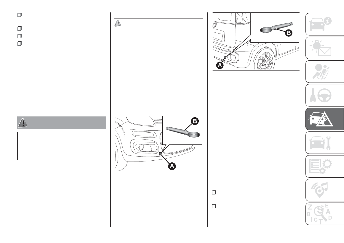
deactivate the right direction
indicator;
activate the left direction indicator;
deactivate the left direction indicator;
turn the ignition key to STOP and
then to MAR.
LPG versions: in the event of an
impact, petrol supply is immediately
cut-off, the LPG safety valves are
closed and the injection is interrupted,
switching off the engine.
Natural Power versions: in the event
of an impact, the power supply is
immediately cut off, causing engine
switching off.
WARNING
151) If, after an impact, you smell fuel or
notice leaks from the fuel system, do
not reactivate the system to avoid the risk
of fire.
TOWING THE CAR
152) 153) 154) 155) 156)
The tow hook, if is supplied with the
car, is housed in the tool box, under the
mat in the luggage compartment.
ATTACHING THE TOW
HOOK
Manually remove cap A fig. 125 (front
bumper) or A fig. 126 (for versions/
markets, where provided) on the rear
bumper, pressing the lower part, take
the tow hook B from its housing in
the tool box and tighten it completely
on the front or rear threaded pin.
Versions with Dualogic
transmission
Make sure that the transmission is in
neutral (N) (checking that the car moves
when pushed) and proceed in the
same way as for towing a normal car
with a manual transmission. If the
gearbox cannot be put in neutral, do
not tow the car and contact a Fiat
Dealership.
Panda Cross 4x4 and Panda 4x4
versions
The car can only be towed in one of the
following ways (and always with the
engine off, gear set to neutral and
handbrake released):
with all the wheels on the road
surface;
with the front (or rear) wheels raised
or resting on an emergency vehicle
and the rear (or front) wheels resting on
a specific trolley;
125
F1D0094
126
F1D0095
123
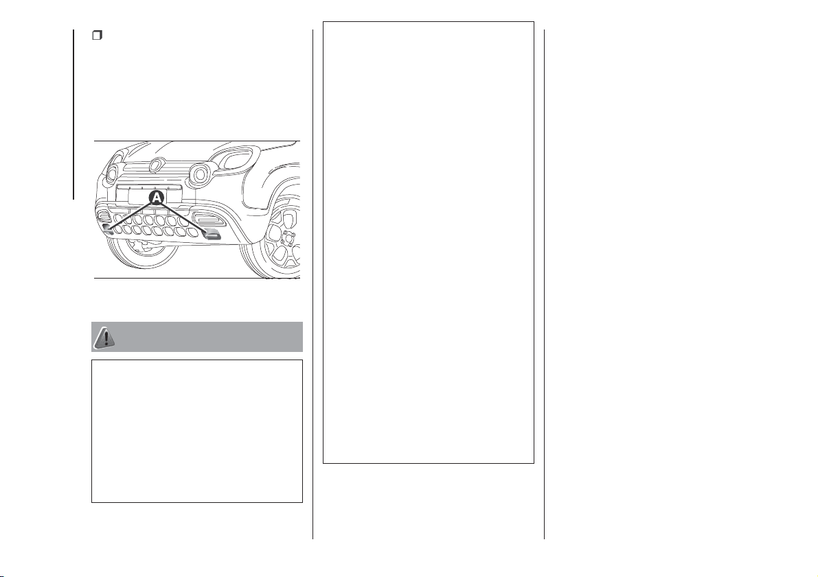
loaded on the flatbed of the rescue
vehicle with all the wheels on the
flatbed.
IMPORTANT On Cross versions, hooks
A fig. 127, if present, can be used to
tow the car in an emergency.
WARNING
152) Before towing, turn the ignition key to
MAR-ON and then to STOP without
removing it. The steering column
will automatically lock when the key is
removed and the wheels cannot be
steered.
153) Before tightening the ring clean the
threaded housing thoroughly. Make sure
that the ring is fully screwed into the
housing before towing the car.
154) Whilst towing, remember that as the
assistance of the brake servo and the
electric power assisted steering is
not available, greater force needs to be
exerted on the brake pedal and more effort
is required on the steering wheel. Do not
use flexible cables when towing and avoid
jerky movements. During towing, make
sure that the trailer hitch does not damage
any components it is touching. When
towing the car, you must comply with all
specific traffic regulations, both in terms of
the towing device and behaviour on the
road. Do not start the engine while towing
the car.
155) The front and rear tow hooks (for
versions/markets, where provided) should
be used only for emergencies on the road.
You are allowed to tow the car for short
distances using an appropriate device
in accordance with the highway code (a
rigid bar), to move the car on the road
in readiness for towing or transporting via a
breakdown car. Tow rings MUST NOT be
used to tow cars off the road or where
there are obstacles and/or for towing
operations using cables or other non-rigid
devices. In compliance with the above
conditions, towing must take place with the
two vehicles (one towing, the other towed)
aligned as much as possible along the
same centre line.
156) Do not use tow hooks for securing the
car on ships.
127
F1D0120
124
IN AN EMERGENCY
SERVICING AND CARE
Correct maintenance permits the
performance of the vehicle to be
maintained over time, as well as limited
running costs and safeguarding the
efficiency of the safety systems.
This chapter explains how.
SCHEDULED SERVICING...............126
BATTERY RECHARGING ................137
ENGINE COMPARTMENT...............139
BRAKES .........................................144
WINDSCREEN / REAR WINDOW
WIPERS ..........................................144
LIFTING THE VEHICLE....................145
WHEELS AND TYRES.....................146
BODYWORK...................................146
INTERIOR .......................................147
125

SCHEDULED
SERVICING
Correct servicing is crucial for
guaranteeing a long life for the car
under the best conditions. For
this reason, Fiat has planned a series of
checks and services at fixed distance
intervals and, where provided, at fixed
time intervals, as described in the
Scheduled Servicing Plan.
Before each coupon however you
always need to pay attention to what is
written in the Scheduled Servicing
Plan (e.g. periodically check liquid
levels, tire pressure, etc.).
Scheduled Servicing is offered by all
Fiat Dealerships according to a set time
schedule. If, during each operation, in
addition to the ones scheduled, the
need arises for further replacements or
repairs, these may be carried out with
the owner's explicit agreement only.
If your car is used frequently for towing,
the interval between one scheduled
servicing operation and the next should
be reduced.
IMPORTANT Scheduled Servicing
interventions are set out by the
Manufacturer. Failure to carry them out
can cause the guarantee to decline. It is
advisable to inform a Fiat Dealership of
any small operating irregularities without
waiting for the next scheduled service
deadline.
PERIODIC CHECKS
Every 1,000 km or before long
journeys, check and if necessary, top
up: engine coolant level; brake fluid
level; screen washer fluid level; tyre
inflation pressure and condition; lighting
system operation (headlights, direction
indicators, hazard warning lights, etc.);
screen washer/wiper system operation
and positioning/wear of windscreen/
rear window wiper blades.
Every 3,000 km, check and top up if
required: engine oil level.
For cars with 0.9 TwinAir engines:
every 3,000 km check the engine oil
level and top it up to the maximum level
if necessary.
DEMANDING USE OF THE
CAR
If the car is used under one of the
following conditions: towing a trailer or
motorhome; dusty roads; short (less
than 7-8 km) and repeated journeys
with sub-zero outside temperatures;
engine often idling or driving long
distances at low speed or long periods
of inactivity, the following checks must
be carried out more often than
indicated in the Scheduled Servicing
Plan:
check front disc brake pad condition
and wear;
check the cleanliness of the side,
bonnet and luggage compartment
locks, and the cleanliness and
lubrication of the linkages;
visually inspect conditions of:
engine, gearbox, transmission, pipes
and hoses (exhaust/fuel system/brakes)
and rubber elements (gaiters/sleeves/
bushes, etc.);
check battery charge and battery
fluid level (electrolyte);
visually inspect conditions of the
accessory drive belts;
check and, if necessary, change
engine oil and replace oil filter / pollen
filter / air cleaner.
126
SERVICING AND CARE

SCHEDULED SERVICING PLAN (petrol versions)
WARNING: Once you have carried out the last intervention in the table, continue with the scheduled servicing, maintaining the
frequency indicated in the plan by marking each operation with a dot or dedicated note.
Warning: simply restarting the maintenance from the start of the plan may cause the allowed interval to be exceeded for some
operations!
Thousands of miles 9 18 27 36 45 54 63 72 81 90
Thousands of kilometres 15 30 45 60 75 90 105 120 135 150
Years 12345678910
Check tyre condition/wear and adjust pressure, if
necessary; check the expiry date of the “Fix&Go” repair kit
(for versions/markets, where provided)
Check operation of lighting system (headlights, direction
indicators, hazard warning lights, boot, passenger
compartment, glove compartment, instrument panel
warning lights, etc.)
Check and, if necessary, top up fluid levels (1)
Check exhaust emissions/smokiness
Use the diagnosis socket to check supply/engine
management systems operation, emissions and, for
versions/markets, where provided, engine oil degradation
(1) Always only use the liquids shown in the handbook for topping up after having checked that the system is not damaged.
127

Thousands of miles 9 18 27 36 45 54 63 72 81 90
Thousands of kilometres 15 30 45 60 75 90 105 120 135 150
Years 12345678910
Visually inspect conditions of: exterior bodywork,
underbody protection, pipes and hoses (exhaust, fuel
system, brakes), rubber elements (gaiters, sleeves,
bushes, etc.)
Check windscreen/rear window wiper blade position/wear
Check operation of the windscreen wiper/washer system
and adjust jets, if necessary
Check cleanliness of bonnet and luggage compartment
locks, cleanliness and lubrication of linkage
Check handbrake lever travel and adjust, if necessary
Check and adjust clutch pedal travel (0.9 TwinAir 60CV/
65HP and 1.2 8V 69 HP versions only)
Visually inspect conditions and wear of front disc brake
pads and integrity of pad wear indicator
Visually inspect condition and wear of rear disc brake pads
and integrity of pad wear indicator (Panda Cross 4x4 and
Panda 4x4 versions only)
Visually check condition and wear of rear drum brake
linings (Panda Cross 4x4 and Panda 4x4 versions
excluded)
128
SERVICING AND CARE
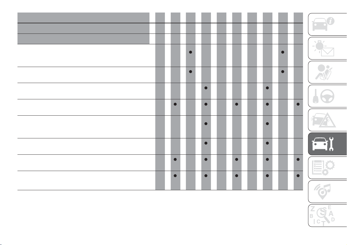
Thousands of miles 9 18 27 36 45 54 63 72 81 90
Thousands of kilometres 15 30 45 60 75 90 105 120 135 150
Years 12345678910
Visually check conditions of accessory drive belt and
control and (for versions without automatic tensioner)
check tension
Visually inspect conditions of toothed timing drive belt (all
0.9 TwinAir versions excluded)
Check tappet clearance and adjust if necessary (1.2 8V 69
HP versions)
Check and, if necessary, top-up the Dualogic gearbox oil
level (2)
Check manual gearbox with drive transmission idler unit
(PTU) oil level (Panda Cross 4x4 and Panda 4x4 versions
only)
Check rear differential oil level (Panda Cross 4x4 and
Panda 4x4 versions only)
Visually inspect condition of: LPG pipes and connectors,
LPG tank fixing (LPG versions only)
Check fuel system operation and parameters using the
diagnosis socket (LPG versions only)
(2) Check to be carried out every year for cars on the road in countries with particularly severe climates (cold countries).
129
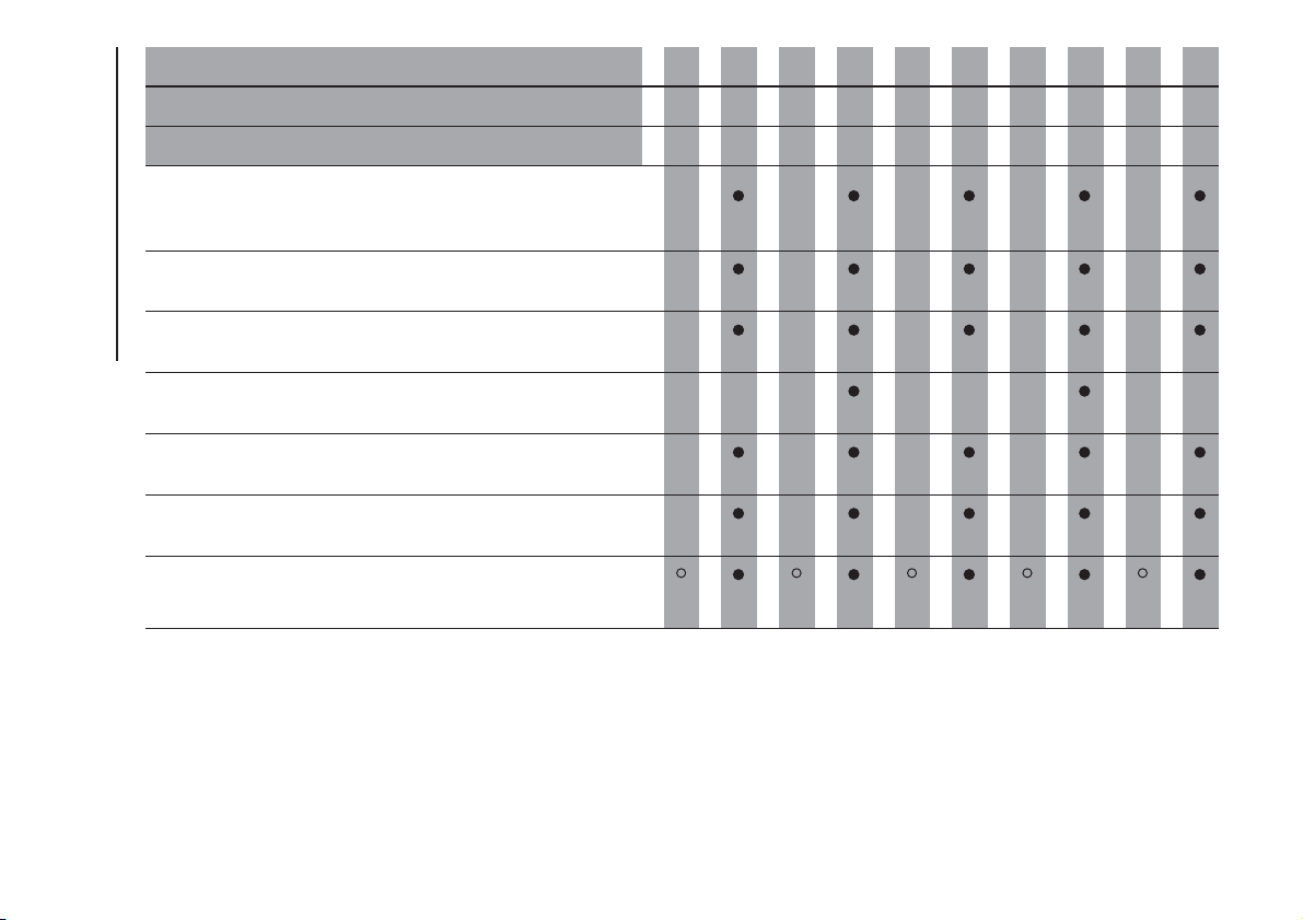
Thousands of miles 9 18 27 36 45 54 63 72 81 90
Thousands of kilometres 15 30 45 60 75 90 105 120 135 150
Years 12345678910
Visually inspect condition of: methane pipes and
connectors and methane cylinder fastening, restore if
necessary (Natural Power versions only) (3)
Check pressure regulator and replace internal filter, if
necessary (Natural Power versions only) (3)
Check fuel system operation and parameters using self-
diagnosis socket (Natural Power versions only)
Check torque tightening of cylinder fastening bands
(Natural Power versions only)
Check pressure regulator heating pipes sealing (Natural
Power versions only)
Check correct fitting of injectors (positioning, clip retention)
(Natural Power versions only)
Change engine oil and replace oil filter (4) (O) (●)
(3) Or every year.
(4) If the car is used mainly on urban routes or the annual distance travelled is less than 10,000 km, the engine oil and engine oil filter must be changed every year.
(O) Recommended operations.
(●) Obligatory operations.
130
SERVICING AND CARE
Thousands of miles 9 18 27 36 45 54 63 72 81 90
Thousands of kilometres 15 30 45 60 75 90 105 120 135 150
Years 12345678910
Replace spark plugs (1.2 8V 69 HP and 0.9 TwinAir Turbo
80 HP/85 HP versions) (5)
Replace spark plugs (0.9 TwinAir 60 HP/65 HP) (5)
Replace accessory drive belt/s
(6)
Replace toothed timing drive belt (all 0.9 TwinAir versions
excluded)
(6)
Replace air cleaner cartridge (7)
(5) For 0.9 TwinAir versions, to guarantee correct operation and prevent serious damage to the engine, it is essential to proceed as follows: only use spark plugs
specifically certified for these engines; all spark plugs should be of the same type and brand (see the "Engine" paragraph in the "Technical specifications"
chapter); strictly comply with the spark plugs replacement intervals in the Service Schedule. It is advisable to contact a FIAT Dealership for plug replacement.
(6) Areas that are not dusty: recommended maximum mileage 120,000 km. The belt must be replaced every 6 years, regardless of distance travelled. Dusty areas
and/or demanding use of the vehicle (cold climates, town use, long periods of idling): advised maximum mileage 60,000 km. Regardless of the mileage, the belt
must be replaced every 4 years.
(7) If the vehicle is used in dusty areas, this cleaner must be replaced every 15,000 km.
131
Thousands of miles 9 18 27 36 45 54 63 72 81 90
Thousands of kilometres 15 30 45 60 75 90 105 120 135 150
Years 12345678910
Change the brake fluid
(8)
Replace filter inside the pressure regulator (LPG versions
only)
Replace paper filter (LPG in gaseous state) (LPG versions
only)
Replace the passenger compartment cleaner (7) (O) (●)
(8) The brake fluid replacement has to be done every two years, irrespective of the mileage.
(7) If the vehicle is used in dusty areas, this cleaner must be replaced every 15,000 km.
(O) Recommended operations.
(●) Obligatory operations.
132
SERVICING AND CARE
DIESEL VERSIONS
WARNING: Once you have carried out the last intervention in the table, continue with the scheduled servicing, maintaining the
frequency indicated in the plan by marking each operation with a dot or dedicated note.
Warning: simply restarting the maintenance from the start of the plan may cause the allowed interval to be exceeded for some
operations!
Thousands of miles 12 24 36 48 60 72 84 96 108 120
Thousands of kilometres 20 40 60 80 100 120 140 160 180 200
Years 12345678910
Check tyre condition/wear and adjust pressure, if
necessary; check the expiry date of the “Fix&Go” repair kit
(for versions/markets, where provided)
Check operation of lighting system (headlights, direction
indicators, hazard warning lights, boot, passenger
compartment, glove compartment, instrument panel
warning lights, etc.)
Check and, if necessary, top up fluid levels (1)
Check exhaust emissions/smokiness
Use the diagnosis socket to check supply/engine
management systems operation, emissions and, for
versions/markets, where provided, engine oil degradation
(1) Always only use the liquids shown in the handbook for topping up after having checked that the system is not damaged.
133
Thousands of miles 12 24 36 48 60 72 84 96 108 120
Thousands of kilometres 20 40 60 80 100 120 140 160 180 200
Years 12345678910
Visually inspect conditions of: exterior bodywork,
underbody protection, pipes and hoses (exhaust, fuel
system, brakes), rubber elements (gaiters, sleeves,
bushes, etc.)
Check windscreen/rear window wiper blade position/wear
Check operation of the windscreen wiper/washer system
and adjust jets, if necessary
Check cleanliness of bonnet and luggage compartment
locks, cleanliness and lubrication of linkage
Check handbrake lever travel and adjust, if necessary
Visually inspect conditions and wear of front disc brake
pads and integrity of pad wear indicator
Visually inspect condition and wear of rear disc brake pads
and integrity of pad wear indicator (Panda Cross 4x4 and
Panda 4x4 versions only)
Visually check condition and wear of rear drum brake
linings (Panda Cross 4x4 and Panda 4x4 versions
excluded)
Visually inspect condition of the accessory drive belt(s)
134
SERVICING AND CARE
Thousands of miles 12 24 36 48 60 72 84 96 108 120
Thousands of kilometres 20 40 60 80 100 120 140 160 180 200
Years 12345678910
Check drive transmission idler unit (PTU) oil level (Panda
Cross and 4x4 Panda 4x4 versions only)
Check rear differential oil level (Panda Cross 4x4 and
Panda 4x4 versions only)
Change engine oil and replace oil filter
(2)
Replace accessory drive belt/s
(3)
Replace fuel filter cartridge (4)
Replace air cleaner cartridge (5)
(2) The actual interval for changing engine oil and replacing the engine oil filter depends on the car usage conditions and is signalled by the warning light or
message in the instrument panel. In any case, it must never exceed 2 years. Where the car is used mostly in urban settings you need to replace the engine oil
filter every year.
(3) Areas that are not dusty: recommended maximum mileage 120,000 km. The belt must be replaced every 6 years, regardless of distance travelled. Dusty areas
and/or demanding use of the vehicle (cold climates, town use, long periods of idling): advised maximum mileage 60,000 km. Regardless of the mileage, the belt
must be replaced every 4 years.
(4) If the car runs on fuel with quality below the relevant European specification, this filter should be replaced every 20,000 km.
(5) If the vehicle is used in dusty areas, this cleaner must be replaced every 20,000 km.
135
Thousands of miles 12 24 36 48 60 72 84 96 108 120
Thousands of kilometres 20 40 60 80 100 120 140 160 180 200
Years 12345678910
Change the brake fluid
(6)
Replace the passenger compartment cleaner (5) (O) (●)
(6) The brake fluid replacement has to be done every two years, irrespective of the mileage.
(5) If the vehicle is used in dusty areas, this cleaner must be replaced every 20,000 km.
(O) Recommended operations.
(●) Obligatory operations.
136
SERVICING AND CARE
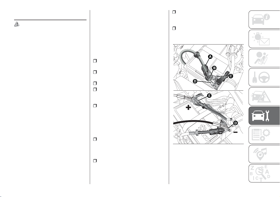
BATTERY
RECHARGING
157) 158)
NOTE After turning the ignition key to
STOP and having closed the driver's
side door, wait at least one minute
before disconnecting and then
reconnecting the electrical supply to the
battery.
IMPORTANT Charging should be slow
at a low ampere rating for
approximately 24 hours. Charging for a
longer time may damage the battery.
IMPORTANT The cables of the
electrical system must be correctly
reconnected to the battery, i.e. the
positive cable (+) to the positive
terminal and the negative cable (–) to
the negative terminal. The battery
terminals are marked with the positive
(+) and negative (–) symbols, and are
shown on the battery cover. The battery
terminals must also be corrosion-free.
IMPORTANT If a "quick-type" battery
charger is used with the battery fitted
on the vehicle, before connecting it
disconnect both cables of the battery
itself. Do not use a "quick-type" battery
charger to provide the starting voltage.
NOTE The battery recharging
procedure is given as information only.
You are advised to contact a Fiat
Dealership to have this operation
carried out.
VERSIONS WITHOUT
START&STOP SYSTEM
(for versions/markets, where provided)
To recharge, proceed as follows:
disconnect the terminal from the
negative battery pole;
connect the charger cables to the
battery terminals, observing the polarity;
turn on the battery charger;
when it is recharged, turn the
charger off before disconnecting it from
the battery;
reconnect the terminal to the
negative battery pole.
VERSIONS WITH
START&STOP SYSTEM
(for versions/markets, where provided)
To recharge, proceed as follows:
disconnect the connector A fig. 128
(pressing the button B) from the sensor
C monitoring the battery conditions,
on the negative pole D of the battery;
connect the positive cable of the
battery charger to the positive battery
pole E and the negative cable to the
terminal of sensor D;
turn on the battery charger. At the
end of the charging process, switch the
battery charger off;
after having disconnected the
charging device, reconnect the
connector A to the sensor C.
128
F1D0136
137
WARNING
157) Battery fluid is poisonous and
corrosive: avoid contact with your skin and
eyes. The battery should be charged in a
well ventilated place, away from naked
flames or possible sources of sparks:
danger of explosion and fire.
158) Do not attempt to recharge a frozen
battery: first it must be thawed, otherwise
there is a risk of explosion. If freezing
has occurred, the battery should be
checked by skilled personnel to make sure
that the internal elements are not damaged
and that the body is not cracked, with the
risk of leaking poisonous and corrosive
acid.
138
SERVICING AND CARE
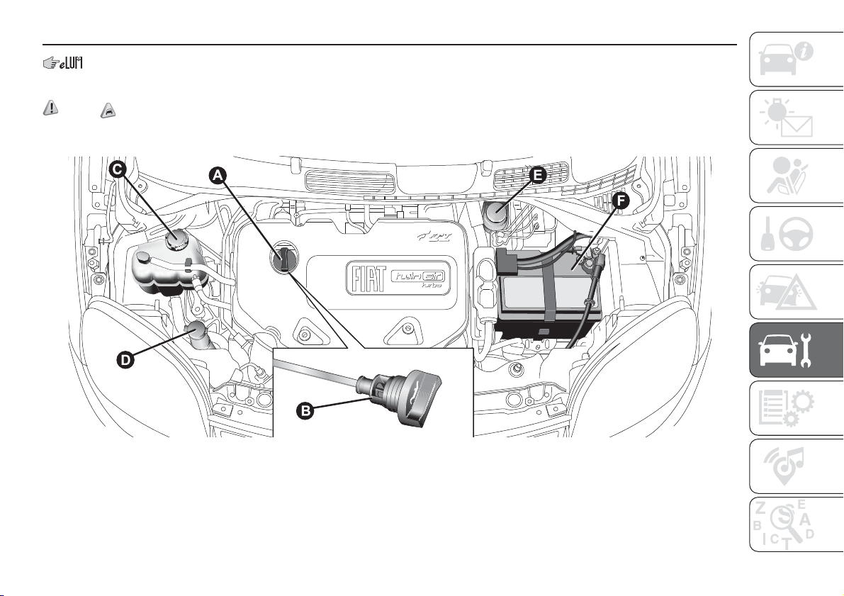
ENGINE COMPARTMENT
.
CHECKING LEVELS
159) 160) 58)
0.9 TwinAir/0.9 TwinAir Turbo versions
A. Engine oil plug/filler – B. Engine oil dipstick – C. Engine coolant fluid – D. Windscreen/rear window washer fluid – E. Brake fluid – F. Battery
129
F1D0097
139
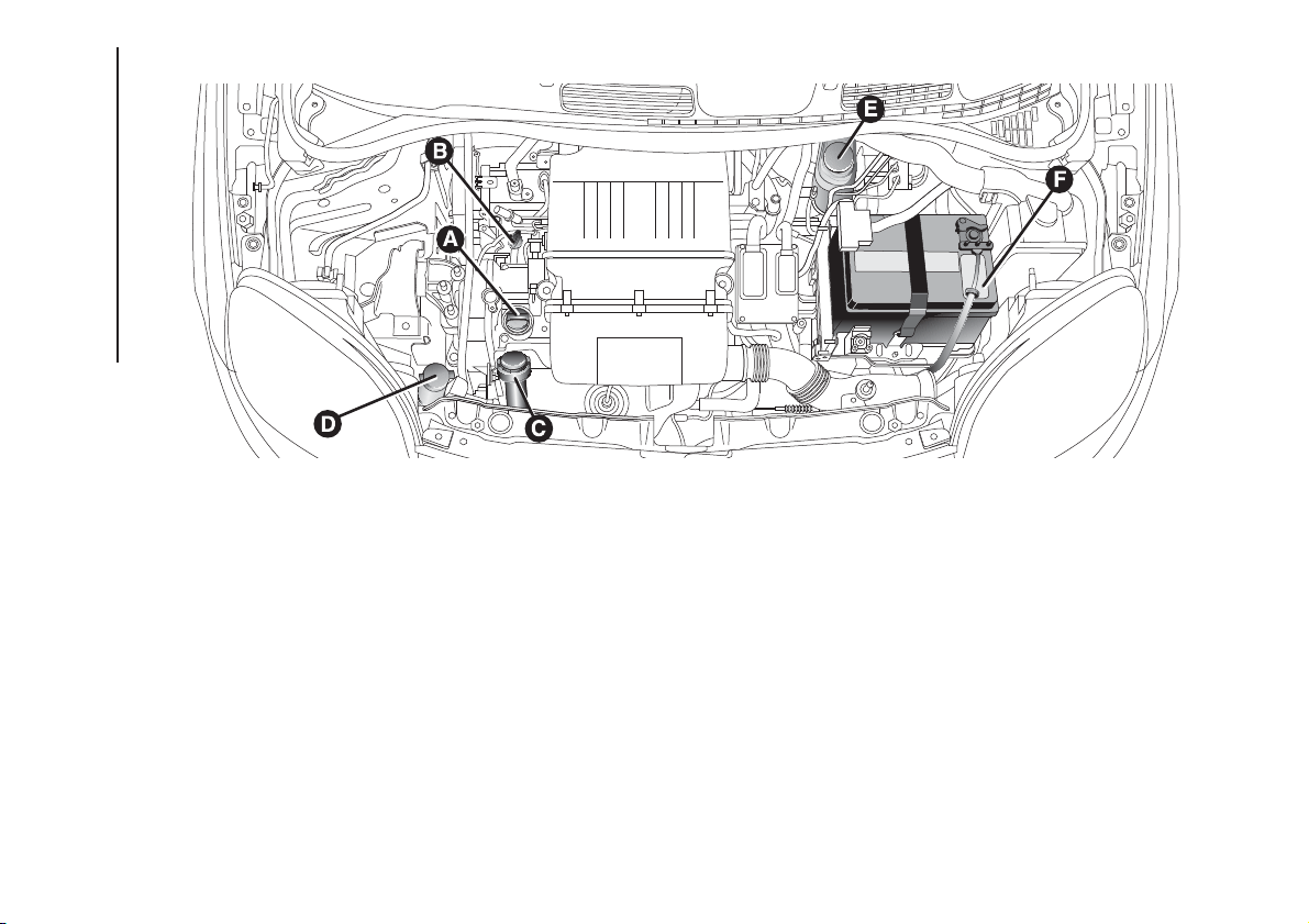
1.2 8V 69 HP versions
A. Engine oil plug/filler – B. Engine oil dipstick – C. Engine coolant fluid – D. Windscreen/rear window washer fluid – E. Brake fluid – F. Battery
130
F1D0098
140
SERVICING AND CARE
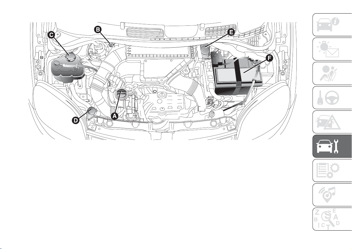
1.3 16V MultiJet versions
A. Engine oil plug/filler – B. Engine oil dipstick – C. Engine coolant fluid – D. Windscreen/rear window washer fluid – E. Brake fluid – F. Battery
131
F1D0141
141
ENGINE OIL
59) 60) 3)
Check the oil level a few minutes (about
5) after the engine has stopped, with
the vehicle parked on level ground.
Check that the oil level is between the
MIN and MAX references on the
dipstick B. If the oil level is near or even
under the MIN mark, add oil using the
filler A to reach the MAX mark.
NOTE For 0.9 TwinAir and 0.9 TwinAir
Turbo versions, the engine oil level
dipstick B is integral with the cap A.
Loosen the plug, clean the dipstick with
a cloth that does not leave traces,
reinsert the dipstick and re-tighten the
plug. Unscrew the cap again and check
that the engine oil level is between the
MIN and MAX marks on the dipstick.
Engine oil consumption
The maximum engine oil consumption
is usually 400 grams every 1000 km.
During the initial period of use the
engine oil consumption conditions
should be considered as having
stabilised after the first 5000 - 6000
km.
Topping up the engine oil (for
TwinAir engines)
If the message requesting an engine oil
top-up appears on the display, the
user must top up the oil to the MAX
level and then reset the warning from
the instrument panel as described
in the "Display" paragraph in the
"Knowing the instrument panel"
chapter.
NOTE After adding or changing the oil,
let the engine turn over for a few
seconds and wait a few minutes after
turning it off before you check the level.
ENGINE COOLANT FLUID
161) 61)
The coolant level must be checked
when the engine is cold and must
range between the MIN and MAX
marks on the reservoir.
If the level is too low, unscrew reservoir
cap C and add the fluid described in
the "Technical Specifications" section.
WINDSCREEN/REAR
WINDOW WASHING FLUID
162)
If the level is too low, raise reservoir cap
D (see previous pages) and add the
fluid described in the chapter "Technical
Specifications".
BRAKE FLUID
163) 164) 62)
Check that the fluid is at the maximum
level (the fluid level in the reservoir
must not exceed the MAX mark). If the
fluid level in the reservoir is too low,
undo reservoir cap E and add the fluid
described in the "Technical
Specifications" chapter.
DUALOGIC GEARBOX
HYDRAULIC ACTIVATION
SYSTEM OIL
4)
The fluid level should only be checked
at a Fiat Dealership.
BATTERY
165) 166) 167) 168)
63) 5)
Battery F does not require topping up
the electrolyte with distilled water. A
periodic check carried out at a Fiat
Dealership is, however, necessary to
check efficiency.
142
SERVICING AND CARE
IMPORTANT After the battery is
disconnected, the steering must be
initialised. The
warning light on the
instrument panel switches on to
indicate this. To carry out this
procedure turn the steering wheel all
the way from one end to the other
or drive in a straight line for about a
hundred metres.
IMPORTANT If the charge level remains
under 50% for a long time, the battery
is damaged by sulphation, reducing
its capacity and efficiency at start-up.
CLIMATE CONTROL
SYSTEM MAINTENANCE
In winter, the climate control system
must be turned on at least once a
month for about 10 minutes. Before
summer, have the system checked at a
Fiat Dealership.
WARNING
159) Never smoke while working in the
engine compartment: gas and inflammable
vapours may be present, with the risk of
fire.
160) Be very careful when working in the
engine compartment when the engine
is hot: you may get burned.
161) The cooling system is pressurised. If
necessary, only replace the plug with
another original or the operation of the
system may be adversely affected. Do not
remove the reservoir plug when the engine
is hot: you risk scalding yourself.
162) Do not travel with the windscreen
washer fluid reservoir empty: the
windscreen washer is essential for
improving visibility. Some commercial
windscreen washer additives are
flammable. The engine compartment
contains hot components which may set it
on fire.
163) Brake fluid is poisonous and highly
corrosive. In the event of accidental
contact, immediately wash the affected
parts with water and mild soap. Then rinse
thoroughly. Call a doctor immediately if
swallowed.
164) The symbol
, on the brake fluid
container indicates if a brake fluid is
synthetic or mineralbased. Use of mineral
type fluids will damage the special rubber
seals of the braking system beyond repair.
165) Battery fluid is poisonous and
corrosive. Avoid contact with the skin and
eyes. Keep naked flames and sources
of sparks away from the battery: risk of
explosion and fire.
166) Using the battery with insufficient
fluid irreparably damages the battery and
may cause an explosion.
167) If the car will be unused for an
extended period of time in extremely cold
weather conditions, remove the battery
and store it in a heated area to prevent it
from freezing.
168) Always wear appropriate goggles
when working on or near the battery.
WARNING
58) Be careful not to confuse the various
types of fluids while topping up: they
are not compatible with each other!
Topping up with an unsuitable fluid could
severely damage your car.
59) The oil level must never exceed the
MAX reference.
60) Do not add oil with specifications other
than those of the oil already existing in
the engine.
61) PARAFLU
UP
antifreeze is used in the
engine cooling system. Use the same fluid
as in the cooling system when topping
up. PARAFLU
UP
fluid cannot be mixed
with any other type of fluid. If this occurs,
do not start the engine and contact your
Fiat Dealership immediately.
62) Prevent brake fluid, which is highly
corrosive, from coming into contact with
painted parts. Should it happen,
immediately wash with water.
63) Incorrect installation of electric and
electronic devices may cause severe
damage to your car. After purchasing your
vehicle, if you wish to install any
accessories (anti-theft, phone, etc.),
contact a Fiat Dealership, which
will suggest the most appropriate devices
for your vehicle, and will, most importantly,
advise you if a higher capacity battery
needs to be installed.
143
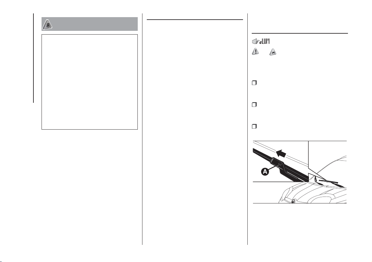
WARNING
3) Used engine oil and oil filters contain
substances which are harmful to the
environment. To change the oil and filters,
we advise you to contact a Fiat Dealership.
4) Used transmission fluid contains
substances that are harmful to the
environment. It is advisable to have the oil
changed by a Fiat Dealership where it
will be disposed of respecting the
environment and according to legal
requirements.
5) Batteries contain substances which are
very dangerous for the environment. For
battery replacement, contact a Fiat
Dealership.
BRAKES
Depending on the version/market, the
vehicle may be equipped with
mechanical wear detectors for the
brake pads: one for each wheel
assembly.
When the brake linings are close to
wearing out, pressing the brake pedal
will generate a slight squeal: this lasts
for about 100 km (the mileage varies
with the driving style and route).
In this case, it is still possible to
continue driving, with caution.
However, contact a Fiat Dealership as
soon as possible to have the worn
brake pads changed.
WINDSCREEN /
REAR WINDOW
WIPERS
169) 64)
REPLACING THE
WINDSCREEN WIPER
BLADES
raise the wiper arm, press tab A fig.
132 of the attachment spring and
remove the blade from the arm;
fit the new blade, inserting the tab
into the special slot in the arm, making
sure that it is locked;
lower the wiper arm onto the
windscreen.
132
F1D0100
144
SERVICING AND CARE
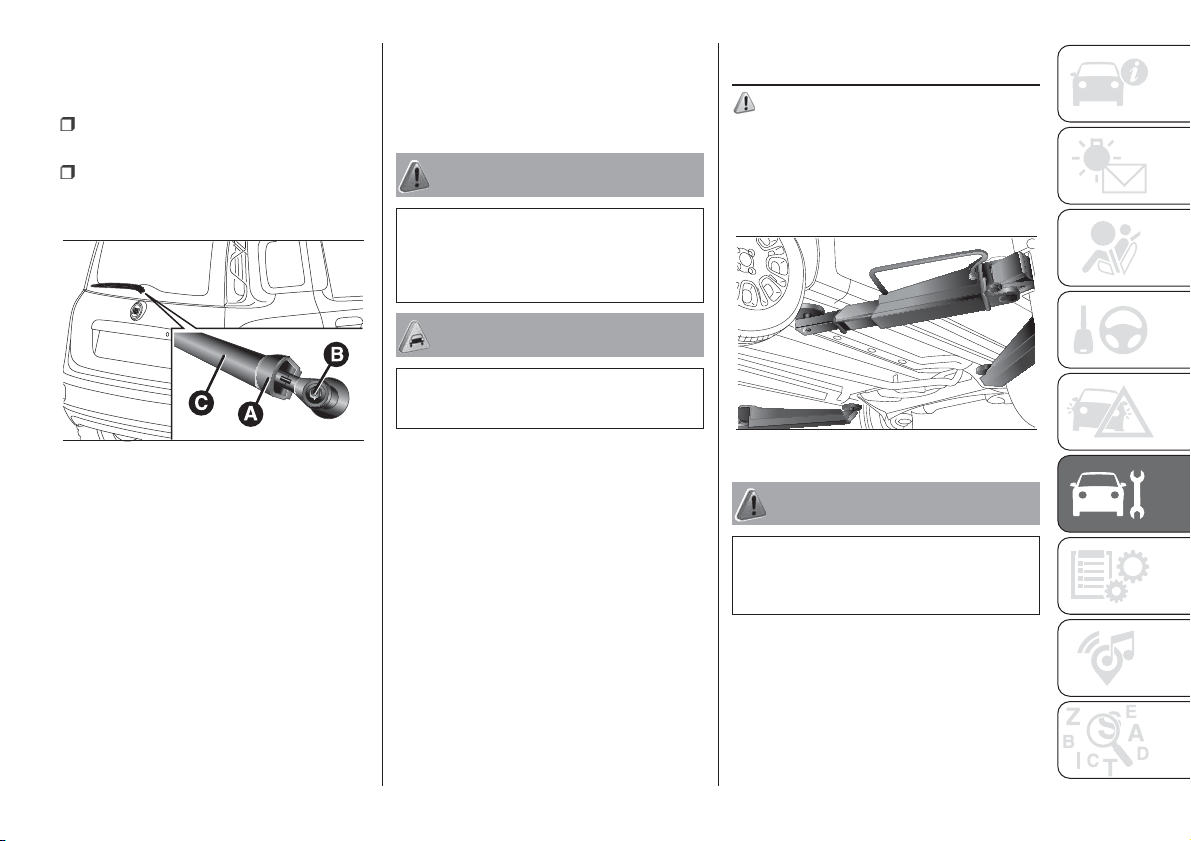
REPLACING THE REAR
WINDOW WIPER BLADE
Proceed as follows:
raise the cover A fig. 133, undo the
nut B and remove the arm C;
correctly position the new arm, fully
tighten the nut B then lower the cover
A.
NOZZLES
Windscreen washer
The windscreen washer jets can be
adjusted rotating the side notch with a
screwdriver. If there is no jet of fluid,
firstly check that there is fluid in the
reservoir (see the "Checking fluid levels"
paragraph in this chapter). Then check
that the nozzle holes are not clogged;
use a needle to unblock them if
necessary.
Rear window washer
The rear window washer jets are fixed.
The nozzle holder is located above
the rear window.
WARNING
169) Driving with worn windscreen/rear
window wiper blades is a serious risk,
because visibility is reduced in bad
weather.
WARNING
64) Do not operate the windscreen wiper
with the blades lifted from the windscreen.
LIFTING THE
VEHICLE
170)
If the vehicle needs to be raised, go to
a Fiat Dealership which is equipped
with arm lifts and workshop lifts fig.
134.
WARNING
170) Lift the vehicle exclusively by
positioning the jack arms or the workshop
jack in the points illustrated.
133
F1D0101
134
F1D0135
145
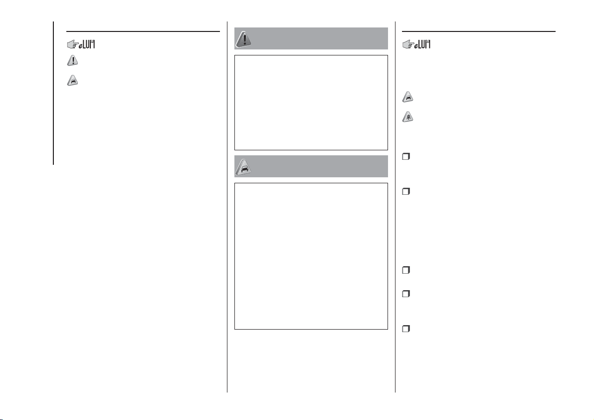
WHEELS AND TYRES
171) 172)
65) 66) 67) 68)
SUGGESTIONS ABOUT
THE ROTATION OF THE
TYRES
The front and rear tyres are subject to
different loads and stress due to
steering, manoeuvres and braking. For
this reason they are subject to uneven
wear.
To resolve this problem, tyres should be
rotated at the appropriate time. This
operation is recommended for tyres
with a deep tread pattern, suitable both
for on-road and off-road driving.
Tyre rotation contributes to the
preservation of the grip and traction
performance on wet, muddy or snowy
roads, guaranteeing optimal driveability
of the car.
In the case of irregular wear of the
tyres, the reason must be identified and
corrected before rotating them.
WARNING
171) Do not cross switch the tyres if they
are "unidirectional" type. In this case,
always take care not to fit the tyres with a
direction of rotation that is opposite to that
indicated: you would risk losing grip and
control of the vehicle.
172) Travelling with partially or completely
deflated tyres can cause safety problems
and irremediably damage the tyre.
WARNING
65) The road holding qualities of the car
also depend on the correct inflation
pressure of the tyres.
66) If tyre pressure is too low, the tyre may
overheat and be severely damaged as a
result.
67) Do not switch tyres from the righthand
side of the vehicle to the lefthand side,
and vice versa.
68) Never submit alloy rims to repainting
treatments requiring the use of
temperatures exceeding 150°C. The
mechanical properties of the wheels could
be impaired.
BODYWORK
PRESERVING THE
BODYWORK
Paintwork
69)
6)
To wash the car correctly, proceed as
follows:
remove the aerial from the roof to
prevent damage to it if the car is
washed in an automatic system;
if high pressure jets or cleaners are
used to wash the vehicle, keep a
distance of at least 40 cm from the
bodywork to avoid damage or
alteration. It should be remembered
that the build up of water can damage
the car over a period of time;
wash the bodywork using a low
pressure jet of water;
wipe a sponge with a slightly soapy
solution over the bodywork, frequently
rinsing the sponge;
rinse well with water and dry with a
jet of air or a chamois leather.
146
SERVICING AND CARE
Dry the less visible parts (e.g. door
frames, bonnet, headlight frames etc.)
with special care, as water may
stagnate more easily in these areas.
The car should not be taken to a closed
area immediately, but left outside so
that residual water can evaporate.
Do not wash the car after it has been
left in the sun or with the bonnet hot:
this may alter the shine of the
paintwork.
Exterior plastic parts must be cleaned
in the same way as the rest of the
vehicle.
Avoid parking under trees; the resin
dropped by trees makes the paintwork
go opaque and increases the possibility
of corrosion.
IMPORTANT Bird droppings should be
washed off immediately and thoroughly
as the acid they contain is particularly
aggressive.
WARNING
69) In order to preserve the aesthetic
appearance of the paint abrasive products
and/or polishes should not be used for
cleaning the vehicle.
WARNING
6) Detergents pollute the environment.
Only wash your vehicle in areas equipped
to collect and treat wastewater from this
type of activity.
INTERIOR
173) 174)
SEATS AND FABRIC
PARTS
Remove dust with a soft brush or a
vacuum cleaner.
Rub the seats with a sponge moistened
with a solution of water and neutral
detergent.
WARNING To avoid ruining the
upholstery, do not use acetone, acetic
alcohol, denatured ethyl alcohol or
any highly aggressive solvents or
detergents to clean the fabric parts.
Use spotting agents such as isopropyl
alcohol or dry stain removers.
WARNING
173) Never use flammable products, such
as petrol ether or rectified petrol to clean
the inside of the car. The electrostatic
charges which are generated by rubbing
during the cleaning operation may cause a
fire.
174) Do not keep aerosol cans in the
vehicle: they might explode. Aerosol cans
must not be exposed to a temperature
exceeding 50°C. When the vehicle is
exposed to sunlight, the internal
temperature can greatly exceed this value.
147

TECHNICAL DATA
Everything you may find useful for
understanding how your car is made
and works is contained in this chapter
and illustrated with data, tables and
graphics. For the enthusiasts and the
technician, but also just for those who
want to know every detail of their
car.
IDENTIFICATION DATA....................149
ENGINE ..........................................150
WHEELS.........................................154
DIMENSIONS..................................163
WEIGHTS........................................166
REFUELLING ..................................173
FLUIDS AND LUBRICANTS ............175
PERFORMANCE.............................178
FUEL CONSUMPTION....................179
CO
2
EMISSIONS ...........................181
PRESCRIPTIONS FOR HANDLING
THE VEHICLE AT THE END OF ITS
LIFE ................................................183
148
TECHNICAL DATA
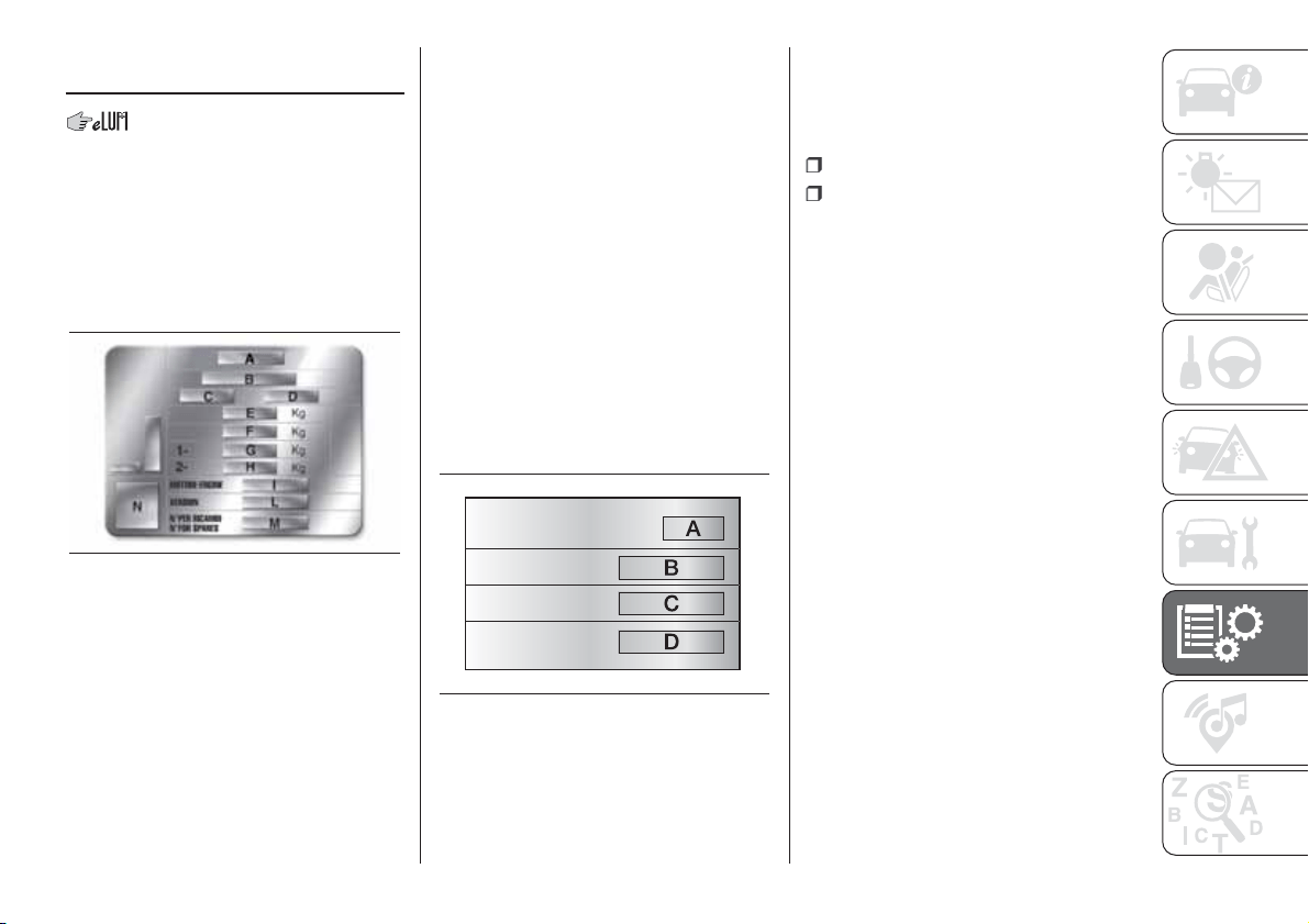
IDENTIFICATION
DATA
VEHICLE IDENTIFICATION
NUMBER (VIN) PLATE
Depending on the version, the plate fig.
135 may be located to the right or at
the centre of the luggage compartment
(lift the carpet covering to access it). It
contains the following data:
A
Name of Manufacturer
B
Type-approval number.
C
Vehicle type identification code.
D
Chassis serial number.
E
Maximum permitted weight of vehicle
fully laden.
F
Maximum permitted weight of vehicle
fully laden plus trailer.
G
Maximum permitted weight on first
axle (front).
H
Maximum permitted weight on
second axle (rear).
I
Engine type.
L
Bodywork version code.
M
Spare part number.
N
Correct value of smoke coefficient
(for diesel engines).
BODYWORK PAINT
IDENTIFICATION PLATE
This is applied inside the bonnet (left
side) and bears the following data
fig. 136:
A Paint manufacturer.
B Colour name.
C Fiat colour code.
D Respray and touch up code.
CHASSIS MARKING
This is located on the right side of the
boot rear floor and gives the following
identification data:
type of vehicle;
chassis serial number.
ENGINE MARKING
It is stamped on the cylinder block and
includes the type and the engine serial
number.
135
F1D0142
136
F1D0128
149
ENGINE
Versions 1.2 8V 69 HP 1.2 8V 69 HP LPG
Engine code 169A4000 169A4000
Cycle Otto Otto
Number and position of cylinders 4 in line 4 in line
Piston bore and stroke (mm) 70.8 × 78.86 70.8 × 78.86
Total displacement (cm³) 1242 1242
Compression ratio 11.1: 1 11.1: 1
LPG Petrol
Maximum power (EC) (kW) 51 51 51
Maximum power (EEC) (HP) 69 69 69
corresponding engine speed (rpm) 5500 5500 5500
Maximum torque (EC) (Nm) 102 102 102
Maximum torque (EC) (kgm) 10.4 10.4 10.4
corresponding engine speed (rpm) 3000 3000 3000
Spark plugs
NGK ZKR7A-10 or
CHAMPION RA8MCX4
NGK ZKR7AI-8
Fuel
Unleaded petrol 95 R.O.N.
(EN 228 specifications)
LPG for motor vehicles
(EN589 Specification)
Unleaded petrol 95 R.O.N.
(EN 228 specifications)
150
TECHNICAL DATA

Versions
0.9 TwinAir 60 HP
(*)
0.9 TwinAir 65 HP
0.9 TwinAir Turbo 80 HP
(*)
Engine code 312A6000 312A4000 312A5000
Cycle Otto Otto Otto
Number and position of cylinders 2 in line 2 in line 2 in line
Piston bore and stroke (mm) 83.5 × 88 83.5 × 88 80.5 × 86
Total displacement (cm³) 964 964 875
Compression ratio 11.1: 1 11.1: 1 10: 1
Maximum power (EC) (kW) 44 48 59
Maximum power (EEC) (HP) 60 65 80
corresponding engine speed (rpm) 6250 6250 5500
Maximum torque (EC) (Nm) 88 88 145
Maximum torque (EC) (kgm) 8.9 8.9 14.8
corresponding engine speed (rpm) 3500 3500 1900
Spark plugs NGK T20182U NGK LKR7DI-12 NGK PLKR9C8
Fuel
Unleaded petrol 95 R.O.N.
(EN 228 specifications)
Unleaded petrol 95 R.O.N.
(EN 228 specifications)
Unleaded petrol 95 R.O.N.
(EN 228 specifications)
(*) For versions/markets, where provided
151

Versions 0.9 TwinAir Turbo 85 HP 0.9 TwinAir Turbo Natural Power
Engine code 312A2000 312A2000
Cycle Otto Otto
Number and position of cylinders 2 in line 2 in line
Piston bore and stroke (mm) 80.5 × 86.0 80.5 × 86.0
Total displacement (cm³) 875 875
Compression ratio 10: 1 10: 1
Methane Petrol
Maximum power (EC) (kW)
62.5 / 57
(*)
59 62.5
Maximum power (EEC) (HP)
85 / 77.5
(*)
80 85
corresponding engine speed (rpm) 5500 5500 5500
Maximum torque (EC) (Nm)
145 / 100
(*)
140 145
Maximum torque (EC) (kgm)
14.8 / 10.2
(*)
14.3 14.8
corresponding engine speed (rpm)
1900 / 2000
(*)
2500 1900
Spark plugs NGK ILKR9G8 NGK ILKR9G8
Fuel
Unleaded petrol 95 R.O.N.
(EN 228 specifications)
Methane for motor vehicles
Unleaded petrol 95 R.O.N.
(EN 228 specifications)
(*) With ECO button pressed
152
TECHNICAL DATA
Versions
0.9 TwinAir Turbo 90 HP
(*)
1.3 16V Multijet 95 HP 1.3 16V MultiJet 80 HP
Engine code 312A7000
312B1000 / 330A1000(°) 312B2000 / 225A2000 (°°)
Cycle Otto Diesel Diesel
Number and position of cylinders 2 in line 4 in line 4 in line
Piston bore and stroke (mm) 80.5 × 86.0 69.6 × 82 69.6 × 82
Total displacement (cm³) 875 1248 1248
Compression ratio 10: 1 16.8: 1 16.8: 1
Maximum power (EC) (kW)
66.2 / 57
(**)
70 59
Maximum power (EEC) (HP)
90 / 77.5
(**)
95 80
corresponding engine speed (rpm) 5500 3750 3750
Maximum torque (EC) (Nm)
145 / 100
(**)
200 200
Maximum torque (EC) (kgm)
14.8 / 10.2
(**)
20.4 20.4
corresponding engine speed (rpm)
1900 / 2000
(**)
1500 1500
Spark plugs NGK ILKR9G8 - -
Fuel
Unleaded petrol 95 R.O.N.
(EN 228 specifications)
Diesel for motor vehicles
(EN590 Specification)
Diesel for motor vehicles
(EN590 Specification)
(*) For versions/markets, where provided
(°) 4x4 and Cross Versions
(°°) 4x4 versions
(**) With ECO button pressed
153
WHEELS
175) 176) 177)
Alloy or pressed steel rims. Tubeless
radial carcass tyres.
All approved tyres are listed in the
Registration Document.
IMPORTANT If there are any
discrepancies between the Owner
Handbook and the Registration
Document, take the information from
the latter. For safe driving, the car must
be fitted with tyres of the same make
and type on all wheels.
IMPORTANT Do not use inner tubes
with Tubeless tyres.
The M+S tyres provided with the
vehicle (on versions where provided) are
characterised by the 3PMSF (3 Peak
Mountain Snow Flake) marking
.
This marking certifies that the tyre has
passed the specific approval test
required by European Community
Regulation ECE 117, which ensures
better performance on snow than
a "simple" M+S.
SNOW CHAINS
178) 179) 180) 70)
Important notes
The use of snow chains should be in
compliance with local regulations of
each country. In certain countries, tyres
marked with code M+S (Mud and
Snow) are considered as winter
equipment; therefore their use is
equivalent to that of the snow chains.
The snow chains may be applied only
to the front wheel tyres.
Check the tension of the snow chains
after the first few metres have been
driven.
Using snow chains with tyres with
non-original dimensions may damage
the vehicle.
Using different size or type (M+S, etc.)
tyres between front and rear axle may
adversely affect car driveability, with the
risk of losing control of the car and
resulting accidents.
Snow chains cannot be fitted to the
space-saver wheel (for versions/
markets, where provided). If a front tyre
is punctured, replace a rear wheel
with the space-saver wheel and move
the rear wheel to the front axle. In
this way, with two normal drive wheels
at the front, snow chains can be fitted.
154
TECHNICAL DATA
RIMS AND TYRES PROVIDED
Panda versions
Versions Wheels Tyres fitted Winter tyres
Space-saver spare
wheel
(*)
0.9 TwinAir 60 HP (*)
5.5J x 14H2 - ET35
175/65 R14 82T
(**)
175/65 R14 82Q (M+S) 135/80 R14 84M
0.9 TwinAir 65 HP
5.5J x 14H2 - ET35
175/65 R14 82T
(**)
175/65 R14 82Q (M+S) 135/80 R14 84M
5.5J x 14H2 - ET35
175/65 R14 82T
Goodyear Duragrip (**)
(***)
175/65 R14 82Q (M+S) 135/80 R14 84M
6J x 15H2 - ET35
(****) 185/55 R15 82T (°)
185/55 R15 82Q (M+S) 135/80 R14 84M
0.9 TwinAir 80 HP
(*)
5.5J x 14H2 - ET35
175/65 R14 82T
(**)
175/65 R14 82Q (M+S) 135/80 R14 84M
0.9 TwinAir Turbo
85 HP
5.5J x 14H2 - ET35
175/65 R14 82T
(**)
175/65 R14 82Q (M+S) 135/80 R14 84M
5.5J x 14H2 - ET35
175/65 R14 82T
Goodyear Duragrip
(**)
(***)
175/65 R14 82Q (M+S) 135/80 R14 84M
6J x 15H2 - ET35
(****) 185/55 R15 82T (°)
185/55 R15 82Q (M+S) 135/80 R14 84M
(*) For versions/markets, where provided.
(**) The tyre can be fitted with size 9 mm snow chains.
(***) For versions/markets, where provided. Tyres offering equivalent performance can be used as an alternative.
(****) Alloy wheel rim.
(°) Not suitable for chains.
155
Versions Wheels Tyres fitted Winter tyres
Space-saver spare
wheel
(*)
0.9 TwinAir Turbo
Natural Power
6Jx15H2-ET35(****) 175/65 R15 84T (°°°)
175/65 R15 84Q (M+S) -
1.2 8V 69 HP
5.5J x 14H2 - ET35
165/65 R14 79T (*)
175/65 R14 79Q (M+S) 135/80 R14 84M
5.5J x 14H2 - ET35
165/70 R14 81T
(*)
175/65 R14 81Q (M+S) 135/80 R14 84M
5.5J x 14H2 - ET35
175/65 R14 82T
(**)
175/65 R14 82Q (M+S) 135/80 R14 84M
6J x 15H2 - ET35
(****) 185/55 R15 82T (°)
185/55 R15 82Q (M+S) 135/80 R14 84M
1.2 8V 69 HP S&S
5.5J x 14H2 - ET35 175/65 R14 82T 175/65 R14 84Q (M+S)
135/80 R14 84P
135/80 R14 80P
reinforced
135/80 R14 84M
6J x 15H2 - ET35 185/55 R15 82T 185/55 R15 82Q (M+S)
6.5J x 16H2 - ET35 195/45 R16 84T 195/45 R16 84Q (M+S)
1.3 16V MultiJet
5.5J x 14H2 - ET35
175/65 R14 82T
(**)
175/65 R14 82Q (M+S) 135/80 R14 84M
6J x 15H2 - ET35 185/55 R15 82H 185/55 R15 82Q (M+S) 135/80 R14 84M
(*) For versions/markets, where provided.
(****) Alloy wheel rim.
(°°°) Tyre to which chains can be fitted, with reduced size chains: 7 mm.
(**) The tyre can be fitted with size 9 mm snow chains.
(°) Not suitable for chains.
156
TECHNICAL DATA

Panda 4x4 versions
Versions Wheels Tyres fitted Winter tyres
Space-saver spare
wheel
(*)
0.9 TwinAir Turbo
85 HP
5.5J x 14H2 - ET35
175/65 R14 82T
(**)
175/65 R14 84Q (M+S) 135/80 R14 84M
5.5J x 14H2 - ET35
175/65 R14 82T
Goodyear Duragrip
(**)
(***)
175/65 R14 84Q (M+S) 135/80 R14 84M
6J x 15H2 - ET35
175/65 R15 84T (M+S)
(°)
175/65 R15 84T (M+S) 125/80 R15 95M
6J x 15H2 - ET35
175/65 R15 84T
(°) (°°)
175/65 R15 84Q (M+S) 125/80 R15 95M
1.3 16V MultiJet
6J x 15H2 - ET35
175/65 R15 84T (M+S)
(°)
175/65 R15 84T (M+S) 125/80 R15 95M
6J x 15H2 - ET35
175/65 R15 84T
(°)
175/65 R15 84Q (M+S) 125/80 R15 95M
(*) For versions/markets, where provided.
(**) The tyre can be fitted with size 9 mm snow chains.
(***) For versions/markets, where provided. Tyres offering equivalent performance can be used as an alternative.
(°) Tyres to which reduced size snow chains can be fitted: 7 mm.
(°°) Tyres available on request.
157
Panda Cross 4x4 versions
Versions Wheels Tyres fitted Winter tyres
Space-saver spare
wheel
(*)
0.9 TwinAir Turbo
90 HP
6 J x 15H2 ET35
175/65 R15 84T (M+S)
(**)
175/65 R15 84T (M+S) 125/80 R15 95M
6 J x 15H2 ET35
175/65 R15 84T
(**)
175/65 R15 84Q (M+S) 125/80 R15 95M
6 J x 15H2 ET30
185/65 R15 88H
(M+S)(***)
185/65 R15 88Q (M+S) 125/80 R15 95M
6 J x 15H2 ET30
185/65 R15 88H
(***)
185/65 R15 88Q (M+S) 125/80 R15 95M
1.3 16V MultiJet
6 J x 15H2 ET35
175/65 R15 84T (M+S)
(**)
175/65 R15 84T (M+S) 125/80 R15 95M
6 J x 15H2 ET35
175/65 R15 84T
(**)
175/65 R15 84Q (M+S) 125/80 R15 95M
6 J x 15H2 ET30
185/65 R15 88H
(M+S)
(***)
185/65 R15 88H (M+S) 125/80 R15 95M
6 J x 15H2 ET30
185/65 R15 88H
(***)
185/65 R15 88Q (M+S) 125/80 R15 95M
(*) For versions/markets, where provided.
(**) The tyre can be fitted with chains.
(***) Tyre not suitable for fitting snow chains.
NOTE For Panda Cross 4x4 and Panda 4x4 versions if the space-saver wheel is used, the control unit for 4x4 drive detects its
presence (via the wheel speed signals) and reduces the intervention of the four-wheel drive to a minimum, while guaranteeing
the agility of the vehicle. No fault/alarm signal is displayed on the instrument panel or on the display.
158
TECHNICAL DATA
Panda Cross 4x2 versions
Versions Wheels Tyres fitted Winter tyres
Space-saver spare
wheel
(*)
1.3 16V Multijet 95 HP
S&S
6 J x 15H2 ET35
175/65 R15 84T (**)
– 125/80 R15 95M
6 J x 15H2 ET30 185/65 R15 88H (M+S) 185/65 R15 88H (M+S) 125/80 R15 95M
1.2 8V 69 HP S&S
6J x 15H2 ET35
175/65 R15 84T
(**)
– 125/80 R15 95M
6J x 15H2 ET30 185/65 R15 88H (M+S) 185/65 R15 88H (M+S) 125/80 R15 95M
(*) For versions/markets, where provided.
(**) The tyre can be fitted with chains.
159
COLD TYRE INFLATION PRESSURE (bar)
When the tyres are warm, the inflation pressure should be + 0.3 bar in relation to the recommended figure. However, recheck
that the value is correct with the tyre cold. With winter tyres the pressure should be +0.2 bar compared with the recommended
figure for the tyres that comes with the vehicle.
Panda versions
Tyres
Unladen/medium load Full load
Space-saver
spare wheel
(*)
Front Rear Front Rear
165/65 R14 79T 2.5 2.2 2.7 2.4 2.8
165/70 R14 81T (*)
2.3 2.0 2.5 2.2 2.8
175/65 R14 82T
2.2 / 2.5
(**)
2.0 / 2.5 (**) /
2.1
(***)
2.5 2.5 2.8
185/55 R15 82T 2.2 2.0 2.5 2.5 2.8
185/55 R15 82H 2.2 2.0 2.5 2.5 2.8
(*) For versions/markets, where provided
(**) 0.9 TwinAir 60 HP/80 HP engines
(***)Natural Power versions
160
TECHNICAL DATA
Panda Cross 4x2 / Panda Cross 4x4 / Panda 4x4 versions
Tyres
Unladen/medium load Full load
Space-saver
spare wheel
(°)
Front Rear Front Rear
175/65 R14 82T M+S
(*)
2.2 2.1 2.5 2.5 4.2
175/65 R15 84T
(*)
2.2 2.1 2.5 2.5 4.2
175/65 R15 84T
(**)
2.4 2.2 2.7 2.7 4.2
185/65 R15 88H
(**)
2.4 2.2 2.7 2.7 4.2
(°) For versions/markets, where provided.
(*) For Panda 4x4 versions
(**) For Panda Cross versions
NOTE For Panda Cross 4x4 and Panda 4x4 versions, do not drive deliberately for long distances with the tyres flat (not at the
prescribed pressure) and/or with greatly varying pressures between front axle and rear axle, in order to avoid any malfunction of
the 4x4 drive.
.
WARNING
175) The top speed for winter tyres marked “Q” is 160 km/h, while it is 190 km/h for “T” tyres and 210 km/h for "H" tyres. The highway code
speed limits must however always be complied with.
176) 185/55 R15 82T tyres cannot be fitted with chains.
177) 175/65 R14 82T tyres can be fitted with reduced size snow chains: 9 mm.
178) 175/65 R15 84T tyres can be fitted with reduced size snow chains: 7 mm.
179) Keep the vehicle's speed down when snow chains are fitted; never exceed 50 km/h. Avoid potholes, do not drive over steps or
pavements and do not drive long distances over roads without snow, to avoid damaging both your vehicle and the road surface.
180) DO NOT fit wheel hub caps when using integral hub caps fixed (with springs) to the steel rim and after sale tyres provided with Rim
Protector. Use of unsuitable tyres and wheel caps may cause sudden decrease of tyre pressure.
161
WARNING
70) With snow chains, use the accelerator with extreme care to prevent, or to limit as much as possible, slipping of the drive wheels that
could cause chain breakage, resulting in damage to the car body or mechanical components.
162
TECHNICAL DATA
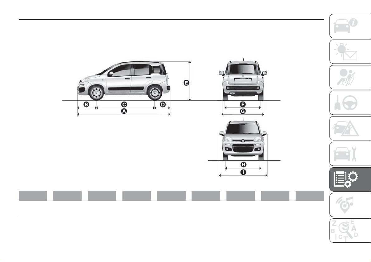
DIMENSIONS
Dimensions are expressed in mm and refer to the car equipped with its original tyres. Height is measured with car unladen.
LUGGAGE COMPARTMENT CAPACITY Capacity (VDA standards) =225 litres
Panda versions
ABCDEFGH I
3653 747 2300 606
1551 /
1605
(*)
1407 /
1408
(*)
1643
1409 /
1414
(*)
1882
(*) Natural Power versions.
137
F1D0103
163
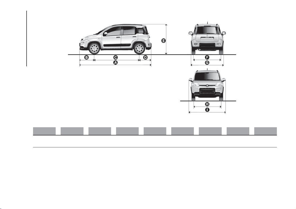
Panda 4x4 versions
ABCDEFGH I
3686 /
3653
(*)
765 / 747 2300
621 / 606
(*)
1605 1408
1672 /
1643
(*)
1411 1882
(*) VAN versions.
138
F1D0104
164
TECHNICAL DATA
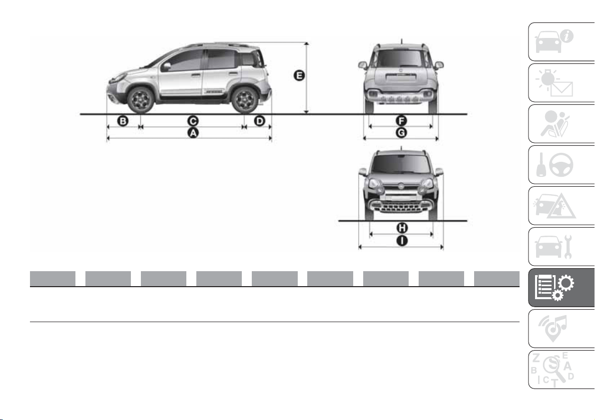
Panda Cross versions
ABCDEFGH I
3705 772.5 2300 632.5
1656.5 /
1635
(*)
1406 /
1412
(*) –
1422
(*)
1662
1403 /
1416
(*) –
1426
(*)
1882
(*) Panda Cross 4x2 versions
139
F1D0121
165
WEIGHTS
Panda versions
Weights (kg) 0.9 TwinAir 60HP / 65HP
0.9 TwinAir Turbo
80HP / 85HP
0.9 TwinAir Turbo
Natural Power
Unladen weight (with all fluids, fuel tank 90% full and
without optional equipment):
955 975 / 980
1080/1090 (***)
Payload including the driver: (*)
480 (4-seater) /
500 (5-seater)
480 (4-seater) /
500 (5-seater)
460 (4-seater) /
450
(***) (4-seater) /
470 (5-seater) /
460
(***) (5-seater)
Maximum permitted loads
(**)
- front axle: 770 855 875
– rear axle: 760 760 810
- total:
1435 (4-seater) /
1455 (5-seater)
1455 (4 seats) /
1460 (4 seats)
(°) /
1475 (5-seater) /
1480 (5-seater)
(°)
1540 (4-seater) /
1550 (5-seater)
Towable loads
– braked trailer: 800 800
(°°)
(***) For versions/markets, where foreseen
(*) If special equipment is fitted (trailer towing equipment, etc.) the empty weight will increase and consequently the payload will decrease in relation to the maximum
permitted loads.
(**) Loads not to be exceeded. The user is responsible for arranging goods in the luggage compartment and/or on the load platform within the maximum permitted
loads.
(°) Versions equipped with the "Dualogic" gearbox
(°°) IMPORTANT A trailer cannot be towed so there are no provisions for fitting a tow hook.
166
TECHNICAL DATA
Weights (kg) 0.9 TwinAir 60HP / 65HP
0.9 TwinAir Turbo
80HP / 85HP
0.9 TwinAir Turbo
Natural Power
– non-braked trailer: 400 400
(°°)
Maximum load on roof: 55 55 55
Maximum load on ball joint (braked trailer): 60 60
(°°)
(°°) IMPORTANT A trailer cannot be towed so there are no provisions for fitting a tow hook.
167
Weights (kg) 1.2 8V 69 HP 1.2 8V 69 HP LPG
1.3 16V Multijet
80HP/95HP
Unladen weight (with all fluids, fuel tank 90% full and
without optional equipment):
940/965
(****)
980 1045
Payload including the driver: (*)
480 (4-seater) /
455
(****) (4-seater) / 500
(5-seater) / 475(****)
(5-seater)
470
480 (4-seater)
(1) / 470
(4-seater)
(2) / 500
(5-seater)
(1) / 490
(5-seater)
(2)
Maximum permitted loads (**)
- front axle: 770 770 855
– rear axle: 760 760 760
- total:
1420 (4-seater) / 1440
(5-seater)
1450
1515 (4-seater) /
1535 (5-seater)
Towable loads
– braked trailer: 800
(***)
900
– non-braked trailer: 400
(***)
400
Maximum load on roof: 55 55 55
Maximum load on ball joint (braked trailer): 60
(***)
60
(****) For versions/markets, where foreseen
(*) If special equipment is fitted (trailer towing equipment, etc.) the empty weight will increase and consequently the payload will decrease in relation to the maximum
permitted loads.
(1) 80 HP
(2) 95 HP
(**) Loads not to be exceeded. The user is responsible for arranging goods in the luggage compartment and/or on the load platform within the maximum permitted
loads.
(***) IMPORTANT A trailer cannot be towed so there are no provisions for fitting a tow hook.
168
TECHNICAL DATA
Panda Cross and Panda 4x4 versions
Weights (kg)
0.9 TwinAir Turbo
85 HP
0.9 TwinAir Turbo
90 HP
1.2 8V 69 HP
1.3 16V Multijet
80HP/95HP
Unladen weight (with all fluids, fuel tank
90% full and without optional
equipment):
1050 1090 1000
1125 (°) / 1090 (°°) /
1165
(°°°)
Payload including the driver: (*)
480 (4-seater) /
500 (5-seater)
440 (4 seats) /
495 (5 seats)
455 (4 seats) /
475 (5 seats)
470 (4-seater)
(°) /
425 (4-seater)
(°°) /
430 (4-seater)
(°°°) /
490 (5-seater) (°) /
445 (5-seater)
(°°) /
460 (5-seater)
(°°°)
Maximum permitted loads (**)
- front axle: 875 875 855
875 / 855
(°°)
– rear axle: 810 810 760
810 / 760
(°°)
(°) Panda 4x4 versions
(°°) Panda Cross 4x2 versions
(°°°) Panda Cross 4x4 versions
(*) If special equipment is fitted (trailer towing equipment, etc.) the empty weight will increase and consequently the payload will decrease in relation to the maximum
permitted loads.
(**) Loads not to be exceeded. The user is responsible for arranging goods in the luggage compartment and/or on the load platform within the maximum permitted
loads.
169
Weights (kg)
0.9 TwinAir Turbo
85 HP
0.9 TwinAir Turbo
90 HP
1.2 8V 69 HP
1.3 16V Multijet
80HP/95HP
- total:
1530 (4-seater) /
1550 (5-seater)
1530 (4 seats) /
1585 (5 seats)
1455 (4 seats) /
1475 (5 seats)
1595 (4 seats) /
1515 (4 seats) (°°) /
1615 (5-seater) (°) /
1535 (5-seater)
(°°) /
1625 (5-seater) (°°°)
Towable loads
– braked trailer: 800 800 800 900
– non-braked trailer: 400 400 400 400
Maximum load on roof: 55
60 (***)
60
60
(***) (°°°°)
Maximum load on ball joint (braked
trailer):
60 60 60 60
(°°) Panda Cross 4x2 versions
(°) Panda 4x4 versions
(°°°) Panda Cross 4x4 versions
(***) Load evenly distributed
(°°°°) Panda Cross 4x2 and 4x4 versions
170
TECHNICAL DATA
Panda VAN versions
Weights (kg) 0.9 TwinAir 65 HP
0.9 TwinAir Turbo
85 HP
0.9 TwinAir Turbo
85 HP 4x4
0.9 TwinAir Turbo
Natural Power
Unladen weight (with all fluids, fuel tank
90% full and without optional
equipment):
950 (2-seater) /
960 (4-seater)
980 1035 1075
Payload including the driver:
(*)
505 (2-seater) /
490 (4-seater)
500 (2 seats) /
490 (4 seats)
510
420
(°) / 460
Maximum permitted loads
(**)
- front axle: 770 855 875 875
– rear axle:
770 (2-seats /
780 (4-seats)
770 (2 seats) /
780 (4 seats)
810 810
- total:
1455 (2-seats) /
1450 (4-seats)
1480 (2 seats) /
1470 (4 seats)
1545
1495
(°) / 1535
Towable loads
– braked trailer: 800 800 800
(***)
– non-braked trailer: 400 400 400
(***)
Maximum load on roof: 60 60 60 60
Maximum load on ball joint (braked
trailer):
60 60 60
(***)
(*) If special equipment is fitted (trailer towing equipment, etc.) the empty weight will increase and consequently the payload will decrease in relation to the maximum
permitted loads.
(°) Versions with reduced capacity
(**) Loads not to be exceeded. The user is responsible for arranging goods in the luggage compartment and/or on the load platform within the maximum permitted
loads.
(***) IMPORTANT A trailer cannot be towed so there are no provisions for fitting a tow hook.
171
Weights (kg) 1.2 8V 69 HP 1.2 8V 69 HP LPG
1.3 16V MultiJet
80 HP
1.3 16V MultiJet 4x4
80 HP
Unladen weight (with all fluids, fuel tank
90% full and without optional
equipment):
935 (2-seater) /
945 (4-seater)
975
1040 (2-seater) /
1050 (4-seater)
1110
Payload including the driver:
(*)
505 (2-seater) /
490 (4-seater)
470
400 (2-seater) (°) /
495 (2-seater) /
485 (4-seater)
485
Maximum permitted loads (**)
- front axle: 770 770
855 (2-seater) /
875 (4-seater)
875
– rear axle:
770 (2-seats) /
780 (4-seats)
770
770 (2-seats) /
780 (4-seats)
810
- total:
1440 (2-seater) /
1435 (4-seater)
1445
1440 (2-seater)
(°) /
1535 (2-seater) /
1535 (4-seater)
1595
Towable loads
– braked trailer: 800 (***) 900 900
– non-braked trailer: 400
(***)
400 400
Maximum load on roof: 60 60 60 -
Maximum load on ball joint (braked
trailer):
60
(***)
60 60
(*) If special equipment is fitted (trailer towing equipment, etc.) the empty weight will increase and consequently the payload will decrease in relation to the maximum
permitted loads.
(°) Versions with reduced capacity
(***) IMPORTANT A trailer cannot be towed so there are no provisions for fitting a tow hook.
172
TECHNICAL DATA
(**) Loads not to be exceeded. The user is responsible for arranging goods in the luggage compartment and/or on the load platform within the maximum permitted
loads.
REFUELLING
0.9 TwinAir
60 HP/65 HP
0.9 TwinAir
Turbo
1.2 8V 69 HP
Panda / Panda
Cross 4x2
Recommended fuels and original lubricants
Fuel tank (litres): 37 37 37
Unleaded petrol with RON no lower than 95
(EN228 specifications)
including a reserve of (litres): 5 ÷ 7 5 ÷ 7 5 ÷ 7
Engine cooling system 4.8 5.2 4.6
Mixture of distilled water and PARAFLU
UP
liquid
at 50%
(**)
Engine sump (litres): 2.8 2.8 2.5
SELENIA DIGITEK P.E (0.9 TwinAir and 0.9
TwinAir Turbo versions) / SELENIA K P.E. (1.2 8V
69 HP versions) / SELENIA MULTIPOWER GAS
5W-40 (LPG versions)
Engine sump and filter (litres): 3.2 3.2 2.8
Gearbox casing/differential: 1.65 (litres)
1.65 (litres) /
(1.7) kg
(***)
1.65 (litres)
TUTELA TRANSMISSION TECHNYX (0.9
TwinAir and 0.9 TwinAir Turbo versions) /
TUTELA TRANSMISSION GEARFORCE (1.2 8V
69HP, LPG and Natural Power versions)
Rear differential (kg)
(***)
:
- 0.62 - TUTELA TRANSMISSION CROSS
Dualogic gearbox hydraulic
activation system (litres):
- 0.7 - TUTELA CS SPEED
Hydraulic brake circuit (litres): 0.55 0.55 0.55 TUTELA TOP 4 or TUTELA TOP 4/S
Front and rear windscreen
washer tanks (litres):
2.7 2.7 2.7
Mixture of water and PETRONAS DURANCE
SC35
(**) When the vehicle is used in particularly harsh weather conditions, we recommend using a mixture of 60% PARAFLU
UP
and 40% demineralised water.
(***)Panda Cross 4x4 and Panda 4x4 versions
173
1.3 16V MultiJet
1.3 16V Multijet Panda
Cross / Panda 4x4
Recommended fuels and original
lubricants
Fuel tank (litres): 37 35
Diesel for motor vehicles (EN590
Specification)
including a reserve of (litres): 5 ÷ 7 5 ÷ 7
Engine cooling system 6.3 6.3
Mixture of distilled water and
PARAFLU
UP
liquid at 50% (**)
Engine sump (litres): 3.7 3.7
SELENIA WR FORWARD
Engine sump and filter (litres): 3.9 3.9
Gearbox casing/front differential (kg): 1.8 1.70
TUTELA TRANSMISSION
GEARFORCE
Drive transmission idler unit (PTU) (kg): - 0.39 TUTELA TRANSMISSION MULTIAXLE
Rear differential (kg): - 0.62 TUTELA TRANSMISSION CROSS
Hydraulic brake circuit (litres): 0.55 0.55 TUTELA TOP 4 or TUTELA TOP 4/S
Front and rear windscreen washer tanks
(litres):
2.7 2.7
Mixture of water and PETRONAS
DURANCE SC35
(**) When the vehicle is used in particularly harsh weather conditions, we recommend using a mixture of 60% PARAFLU
UP
and 40% demineralised water.
174
TECHNICAL DATA
FLUIDS AND LUBRICANTS
Your car is equipped with an engine oil that has been thoroughly developed and tested in order to meet the requirements of the
Scheduled Servicing Plan. Constant use of the prescribed lubricants guarantees the fuel consumption and emission
specifications. Lubricant quality is crucial for engine operation and duration. If lubricants conforming to the required
specifications are not available, products that meet the indicated specifications can be used to top up; in this case optimal
performance of the engine is not guaranteed.
71)
Use Features Specification
Original fluids and
lubricants
Replacement interval
Lubricants for petrol
engines and 1.2 8V
69HP
SAE 5W-40 ACEA C3 /
API SN.
9.55535-S2
SELENIA K P.E.
Contractual Technical
Reference N° F603.C07
According to Service
Schedule
Lubricants for petrol
engines 0.9 TwinAir
and 0.9 TwinAir
Turbo
SAE 0W-30 ACEA C2 /
API SN.
9.55535-GS1
SELENIA DIGITEK P.E.
Contractual Technical
Reference N° F020.B12
According to Service
Schedule
Lubricant for petrol/
methane engines
SAE 0W-30 ACEA C2 /
API SN.
9.55535-GS1
SELENIA DIGITEK P.E.
Contractual Technical
Reference N° F020.B12
According to Service
Schedule
Lubricant for petrol/
LPG engines
SAE 5W-40 ACEA C3 /
API SM.
9.55535-T2
SELENIA MULTIPOWER
GAS 5W-40
Contractual Technical
Reference No. F922.E09
According to Service
Schedule
Diesel engine
lubricants
SAE 0W-30 ACEA C2.
9.55535-DS1 or
MS.90047
SELENIA WR FORWARD
Contractual Technical
Reference N° F842.F13
According to Service
Schedule
175
Use Features Specification
Original fluids and
lubricants
Applications
Lubricants and
greases for drive
transmission
SAE 75W- 85 grade
synthetic lubricant.
9.55550-MX3
9.55550-MX3
TUTELA TRANSMISSION
TECHNYX
Contractual Technical
Reference N° F010.B05
Manual gearbox and
differential (0.9 TwinAir and
0.9 TwinAir Turbo versions)
SAE 75W grade synthetic
lubricant.
9.55550-MZ6
TUTELA TRANSMISSION
GEARFORCE
Contractual Technical
Reference N° F002.F10
Manual gearbox and
differential (1.3 16V Multijet,
LPG, and 1.2 8V 69HP and
Natural Power versions)
Fully synthetic oil with
dedicated additive.
9.55550-SA1
TUTELA CS SPEED
Contractual Technical
Reference N° F005.F98
Dualogic gearbox hydraulic
activation system
SAE 75W-85 grade
synthetic lubricant.
9.55550 - DA4
TUTELA TRANSMISSION
CROSS
Contractual Technical
Reference N° F001.D12
Rear differential
(°)
SAE 75W-85 grade
synthetic lubricant, which
exceeds API GL5
specifications.
9.55550 - DA3
TUTELA TRANSMISSION
MULTIAXLE
Contractual Technical
Reference N° F426.E06
Drive transmission idler unit
(PTU)
(°)
Molybdenum disulphide
grease, for use at high
temperatures. N.L.G.I.
consistency 1-2.
9.55580 - GRASS II
TUTELA ALL STAR
Contractual Technical
Reference N° F702.G07
Wheel side constant
velocity joints
Low friction coefficient
grease for constant
velocity joints. N.L.G.I.
consistency 0-1.
9.55580 - GRASS II
TUTELA STAR 700
Contractual Technical
Reference N° F701.C07
Differential side constant
velocity joints
(°) Panda Cross 4x4 and Panda 4x4 versions.
176
TECHNICAL DATA
Use Features Specification
Original fluids and
lubricants
Applications
Brake fluid
Synthetic fluid for brake
and clutch systems.
Exceeds specifications:
FMVSS no. 116 DOT 4,
ISO 4925 SAE J1704.
9.55597 or MS.90039
TUTELA TOP 4
Contractual Technical
Reference N° F001.A93 or
TUTELA TOP 4/S
Contractual Technical
Reference N° F005.F15
Hydraulic brakes and
hydraulic clutch controls
Protective agent for
radiators
Protective agent with
anti-freeze action and
organic formulation. CUNA
NC 956-16, ASTM D 3306
specifications.
9.55523 or MS.90032
PARAFLU
UP
(*)
Contractual Technical
Reference N° F101.M01
Cooling circuits proportions
of use: 50% water 50%
PARAFLU
UP
(**)
Diesel fuel additive
Additive for diesel with
antifreeze and protective
action for diesel engines
-
PETRONAS DURANCE
DIESEL ART
Contractual Technical
Reference N° F601.C06
To be mixed with diesel (25
cc per 10 litres)
Windscreen/rear
window washer fluid
Mixture of spirits and
surfactants. Exceeds
CUNA NC 956-11
specifications.
9.55522 or MS.90043
PETRONAS DURANCE
SC35
Contractual Technical
Reference N° F001.D16
To be used diluted or
undiluted in windscreen
washer/wiper systems
(*) IMPORTANT Do not top up or mix with other fluids which have different specifications from those described.
(**) When the vehicle is used in particularly harsh weather conditions, we recommend using a mixture of 60% PARAFLU
UP
and 40% demineralised water.
WARNING
71) The use of products with different specifications than those indicated below could cause damage to the engine not covered by the
warranty.
177
PERFORMANCE
Top speeds after the initial period of usage of the car.
Versions km/h
0.9 TwinAir 60 HP (*)
158 in 4
th
gear
0.9 TwinAir 65 HP 160
0.9 TwinAir Turbo 80 HP (*)
175
0.9 TwinAir Turbo 80 HP Dualogic
(*)
175
0.9 TwinAir Turbo 85 HP 177
0.9 TwinAir Turbo 85 HP Dualogic
(*)
177
0.9 TwinAir Turbo 85 HP 4x4 166
0.9 TwinAir Turbo 90 HP Cross 4x4 167
0.9 TwinAir Turbo Natural Power
170
(°) / 168(°°)
1.2 8V 69 HP 164
1.2 8V 69 HP LPG 164
1.2 8V 69 HP S&S Cross 4x2 155 in 4
th
gear
1.3 16V MultiJet 80 HP 170
1.3 16V Multijet 80HP 4x4 160
1.3 16V MultiJet 95 HP 182
1.3 16V MultiJet 95 HP 4x4 167
1.3 16V Multijet 95 HP Cross 4x4 168
1.3 16V Multijet 95 HP S&S Cross 4x2 169
(*) For versions/markets, where provided
(°) Running on petrol
(°°) Running on methane
178
TECHNICAL DATA
FUEL CONSUMPTION
The fuel consumption figures given in the tables below are determined on the basis of the type-approval tests laid down by
specific European Directives.
IMPORTANT The type of route, traffic conditions, weather conditions, driving style, general condition of the car, trim level/
equipment/accessories, use of the climate control system, car load, presence of roof racks and other situations that adversely
affect the aerodynamics or wind resistance lead to different fuel consumption values than those measured. The fuel
consumption will get more regular only after having driven the first 3000 km.
FUEL CONSUMPTION ACCORDING TO THE CURRENT EUROPEAN DIRECTIVE (litres/100 km)
NOTE Consumption of methane-fuelled Natural Power versions is intended in m
3
/100 km.
Versions Urban Extra-urban Combined
0.9 TwinAir 60 HP (*)
4.5 3.4 3.8
0.9 TwinAir 65 HP
5.0 / 4.8
(*) 3.8 / 3.7 (*) 4.2 / 4.1 (*)
0.9 TwinAir Turbo 80 HP (*)
4.4 3.4 3.8
0.9 TwinAir Turbo 80 HP Dualogic
(*)
4.4 3.4 3.8
0.9 TwinAir Turbo 85 HP
5.0 / 4.9
(*)
3.8 4.2
0.9 TwinAir Turbo 85 HP Dualogic 4.8 3.7 4.1
0.9 TwinAir Turbo 85 HP 4x4 5.9 4.3 4.9
0.9 TwinAir Turbo 90 HP Cross 4x4 5.9 4.3 4.9
0.9 TwinAir Turbo Natural Power
5.8
(°) / 6.0 (°°) 3.8 (°) / 4.0 (°°) 4.5 (°) / 4.7 (°°)
1.2 8V 69 HP
6.7 / 6.5 (*) / 5.9 (*) 4.3 / 4.2 (*) / 4.0 (*) 5.2 / 5.0 (*) /4.7 (*)
1.2 8V 69 HP S&S 5.9 4.0 4.7
(*) For versions/markets, where provided.
(°) Running on petrol
(°°) Running on methane
179

Versions Urban Extra-urban Combined
1.2 8V 69 HP LPG
6.6 (°) / 6.9 (°°°) 4.3 (°) / 6.3 (°°°) 5.1 (°) / 6.5 (°°°)
1.2 8V 69 HP S&S Cross 4x2 7.3 4.5 5.5
1.3 16V MultiJet 80 HP 4.3 3.2 3.6
1.3 16V Multijet 80HP 4x4 4.7 4.3 4.4
1.3 16V MultiJet 95 HP 4.3 3.2 3.6
1.3 16V MultiJet 95 HP 4x4 4.7 4.3 4.4
1.3 16V Multijet 95 HP Cross 4x4 4.8 4.4 4.8
1.3 16V Multijet 95 HP S&S Cross 4x2 4.3 3.3 3.7
(°) Running on petrol
(°°°) Running on LPG
180
TECHNICAL DATA
CO
2
EMISSIONS
The CO
2
emission levels given in the following tables refer to combined consumption.
Versions
CO
2
EMISSIONS ACCORDING TO CURRENT EUROPEAN DIRECTIVE
(g/km)
0.9 TwinAir 60 HP (*)
88
0.9 TwinAir 65 HP
99/95
(*)
0.9 TwinAir Turbo 80 HP (*)
88
0.9 TwinAir Turbo 80 HP Dualogic
(*)
88
0.9 TwinAir Turbo 85 HP
99/97
(*)
0.9 TwinAir Turbo 85 HP Dualogic 95
0.9 TwinAir Turbo 85 HP 4x4 114
0.9 TwinAir Turbo 90 HP Cross 4x4 114
0.9 TwinAir Turbo Natural Power
106
(°) /85(°°)
1.2 8V 69 HP
120 / 117
(*) / 119 (*) /110 (*)
1.2 8V 69 HP S&S 110
1.2 8V 69 HP LPG
119
(°) / 106 (°°°)
1.2 8V 69 HP S&S Cross 4x2 129
1.3 16V MultiJet 80 HP 94
1.3 16V Multijet 80HP 4x4 117
1.3 16V MultiJet 95 HP 94
1.3 16V MultiJet 95 HP 4x4 117
(*) For versions/markets, where provided.
(°) Running on petrol.
(°°) Running on methane.
(°°°) Running on LPG.
181

Versions
CO
2
EMISSIONS ACCORDING TO CURRENT EUROPEAN DIRECTIVE
(g/km)
1.3 16V Multijet 95 HP Cross 4x4 119
1.3 16V Multijet 95 HP S&S Cross 4x2 97
182
TECHNICAL DATA

PRESCRIPTIONS FOR HANDLING THE VEHICLE AT THE END OF
ITS LIFE
(Where provided)
FCA has been committed for many years to safeguarding the environment through the constant improvement of its production
processes and manufacturing products that are increasingly "eco-compatible". To grant customers the best possible service
in terms of respecting environmental laws and in response to European Directive 2000/53/EC governing vehicles at the end of
their life, FCA is offering its customers the chance to hand over their vehicle at the end of its life without incurring any additional
costs. The European Directive sets out that when the vehicle is handed over, the last keeper or owner should not incur any
expenses as a result of it having a zero or negative market value.
To hand your vehicle over at the end of its life without extra cost, contact one of our dealerships if you are purchasing another
vehicle or an FCA-authorised collection and scrapping centre. These centres have been carefully chosen to offer high quality
service for the collection, treatment and recycling of vehicles at their end of life, respecting the surrounding environment.
You can find further information on these collection and scrapping centres either from an FCA dealership or by calling the
number in the Warranty Booklet or by consulting the websites of the various FCA brands.
183

MULTIMEDIA
This chapter describes the main
functions of the radio and of the
Uconnect Radio that may be fitted on
the vehicle.
RADIO.............................................185
UCONNECT RADIO ........................193
RADIO EQUIPMENT DIRECTIVE
2014/53/EU ....................................208
184
MULTIMEDIA
RADIO
181) 182) 183) 184) 185) 186)
The radio has been designed according
to the specifications of the passenger
compartment, with a personalised
design matching the style of the
dashboard perfectly.
TIPS
Road safety
Please, learn how to use all different
radio functions (e.g. save stations)
before beginning to drive.
Care and maintenance
Clean the cover with a soft anti-static
cloth only. Cleaning and polishing
products may damage the surface.
ANTITHEFT PROTECTION
The radio is equipped with an anti-theft
protection system based on the
exchange of information between the
radio and the electronic control unit
(Body Computer) present on the
vehicle.
This system guarantees maximum
safety and prevents the secret code
from being entered each time the radio
power supply is disconnected.
If the check has a positive outcome, the
radio will start to function, whereas if
the comparison codes are not the
same or if the electronic control unit
(Body Computer) is replaced, the
device will ask the user to enter the
secret code according to the procedure
described in the paragraph below.
Entering the secret code
When the radio is switched on, if the
password is requested, the display will
show "Radio code" for about 2
seconds, followed by four dashes "- - -
-".
The secret code is made up of four
digits from 1 to 6, each corresponding
to one of the dashes.
To enter the first digit of the code, press
the button corresponding to the
pre-selected stations (from 1 to 6).
Enter the other code digits in the same
way.
If the four digits are not entered within
20 seconds, the display shows the text
"Enter code----".Ifthis occurs, it is
not considered an incorrect code entry.
After entering the fourth digit (within
20 seconds), the car radio will work.
If an incorrect code is entered, the radio
will emit a sound and the display will
show "Radio blocked/wait" to notify the
user of the need to enter the correct
code.
Each time the user enters an incorrect
code, the waiting time will gradually
increase (1 min, 2 min, 4 min, 8 min, 16
min, 30 min,1h, 2h, 4h, 8h, 16h, 24h)
up to a maximum of 24 hours.
The waiting time will be shown on the
display with the text "Radio blocked/
wait". After the text has disappeared it
is possible to start the code entering
procedure again.
Vehicle radio passport
This document certifies the ownership
of the vehicle radio. The radio passport
shows the radio model, serial number
and secret code.
IMPORTANT Keep the radio passport in
a safe place so that you can give the
information to the relevant authorities if
the radio is stolen.
In the case of loss of the vehicle radio
passport, contact the Fiat Dealership,
taking an ID document and the vehicle
ownership documents.
185
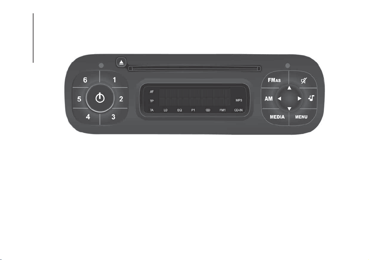
QUICK GUIDE
140
F1D0695
186
MULTIMEDIA
General functions
Button Functions Mode
Switching on short button press
Switching off short button press
Volume adjustment turn knob left/right
FM AS FM1, FM2, FM Autostore radio source selection short cyclical button press
AM MW1, MW2 radio source selection short cyclical button press
MEDIA CD source selection short cyclical button press
Volume activation/deactivation (Mute/Pause) Short button press
Audio adjustments: low tones (BASS), high tones
(TREBLE), RH/LH balance (BALANCE), front/rear
balance (FADER) (where provided)
Menu activation: short button press
Adjustment type selection: press
or buttons.
Value adjustment: press
or buttons.
MENU Advanced functions adjustment
Menu activation: short button press
Adjustment type selection: press
or buttons.
Value adjustment: press
or buttons.
187
Radio functions
Button Functions Mode
Radio station search:
Automatic search
Manual search
Automatic search: press
or buttons (hold the
button down for fast forward)
Manual search: press
or buttons (hold the button
down for fast forward)
123456
Store current radio station Long button press for memory preset from 1 to 6
Stored station recall Brief button press for memory preset from 1 to 6
.
CD functions
Button Functions Mode
CD ejection Short button press
Play previous/next track Brief press of or buttons
Fast forwarding/rewinding CD track Long press of
or buttons
Playing previous/next folder (for CD-MP3) Brief press of or buttons
188
MULTIMEDIA
GENERAL INFORMATION
The radio offers the following functions:
Radio section
PLL tuning with FM/AM/MW
frequency bands;
RDS (Radio Data System) with TA
(traffic alerts) function - TP (traffic
programmes) - EON (Enhanced Other
Network) - REG (regional programmes);
AF: search selection for alternative
frequencies in RDS mode;
provision for emergency alarm;
automatic/manual tuning into
stations;
FM Multipath detector;
manual storing of 30 stations: 18 on
FM band (6 on FM1, 6 on FM2, 6 on
FMT), 12 on MW band (6 on MW1,
6 on MW2);
automatic programming (Autostore
function) of 6 stations on dedicated
FM band
SPEED VOLUME function:
automatic volume adjustment
according to the vehicle speed;
automatic Stereo/Mono selection.
CD section
Direct selection of the disc;
Track selection (forward/back);
Fast advance (forward/back) through
tracks;
CD Display function: display of disc
name and time elapsed since the
start of the track
Playing of audio CDs, CD-Rs and
CD-RWs.
MP3 CD section
MP3-Info function (ID3-TAG);
Folder selection (previous/next);
Track selection (forward/back);
Fast advance (forward/back) through
tracks;
MP3 Display function: display of
name of folder, ID3-TAG information,
time elapsed since the start of the
track, name of the file
Playing of audio or data CD, CD-R
and CD-RW.
Audio section
Mute/Pause function;
Soft-Mute function;
Loudness function
7-band graphic equaliser;
Separate bass/treble adjustment
Right/left channel balance.
FUNCTIONS AND
ADJUSTMENTS
Turning the car radio on
The car radio comes on when the
(ON/OFF) button/knob is pressed
briefly.
When the radio is turned on with the
key extracted from the ignition switch, it
turns off automatically after about 20
minutes. After the radio has switched
itself off automatically it can be turned
on for a further 20 minutes by pressing
the
(ON/OFF) button/knob.
Turning the car radio off
Briefly press the
(ON/OFF)
button/knob.
Volume adjustment
Turn the
(ON/OFF) button/knob to
adjust the volume.
If the volume level is changed during
the transmission of traffic news, the
new setting will only be maintained until
the news is finished.
MUTE/Pause function
(muting the volume)
Press the
button briefly to activate
the Mute function. The volume will
gradually decrease and the words
"RADIO Mute" will be displayed (in radio
mode) or "PAUSE" (in CD mode).
189
Press the button again to deactivate
the Mute function. The volume will
gradually increase until it reaches the
level set previously.
Audio settings
The functions that can be selected from
the audio menu change depending on
the context: AM/FM/CD.
Press the
button briefly to change
the Audio functions.
After the
button is first pressed, the
display will show the bass level value
for the source activated at that time
(e.g. in FM mode the display will show
the wording "FM Bass +2").
Use the
or buttons to scroll
through the menu functions. To change
the setting of the function selected
use the
or buttons. The current
status of the selected function appears
on the display.
The functions managed by the Menu
are:
BASS: adjustment of bass tones;
TREBLE: adjustment of high tones;
BALANCE: right/left balance
adjustment;
FADER: front/back balance
adjustment (where provided).
LOUDNESS: activation/deactivation
of the increase of bass and high tones;
EQUALISER: activation and
selection of factory-set equaliser levels;
USER EQUALIZER: customised
equaliser setting.
MENU
MENU button function
Press the button MENU briefly to
activate the Menu function. The display
will show the first menu item that can
be adjusted (AF) ("AF Switching On" on
the display).
Use the
or buttons to scroll
through the Menu functions. To change
the setting of the function selected
use the
or buttons.
The current status of the selected
function appears on the display.
The functions managed by the Menu
are:
AF SWITCHING: automatic
activation/deactivation of the selection
of the station with the strongest signal
that transmits the same programme.
TRAFFIC INFORMATION:
activation/deactivation of traffic
information (only on FM band).
REGIONAL MODE: activation/
deactivation of regional programmes.
MP3 DISPLAY: CD MP3 display
setting.
SPEED VOLUME: speed-dependent
automatic volume control.
RADIO ON VOLUME: maximum
radio volume limit activation/
deactivation.
RADIO OFF: off mode selection.
SYSTEM RESET: reset of factory
settings.
Press the button MENU again to exit
the Menu function.
NOTE The AF SWITCHING, TRAFFIC
INFORMATION and REGIONAL MODE
adjustments are only possible in FM
mode.
RADIO (Tuner)
To select the Radio function when
another audio source is being listened
to, briefly press the FM, AS or AM
buttons, depending on the desired
band.
Once the Radio mode has been
activated, the display will show the
name (only RDS stations) and the
frequency of the selected radio station,
the frequency band selected (e.g.
FM1) and the preselect button number
(e.g. P1).
Frequency band selection
With the Radio mode active, press the
FM, AS or AM button briefly and
repeatedly to select the desired
reception band.
190
MULTIMEDIA

Each time the button is pressed, the
AM and FM bands are selected
cyclically:
Preset buttons
The buttons numbered from 1 to 6 are
used to set the following preset
stations:
18 in the FM band (6 in FM1, 6 in
FM2, 6 in FMT or "FMA" (on some
versions);
12 in the MW band (6 in MW1, 6 in
MW2).
To listen to a preset station, select the
desired frequency band and then press
the corresponding preset button briefly
(from 1 to 6).
By pressing the preset button for more
than 2 seconds, the tuned station will
be stored. The storing phase is
confirmed by an acoustic signal.
Automatic tuning
Briefly press the
or button to start
the automatic tuning search for the
next station that can be received in the
selected direction.
Manual tuning
Select the desired frequency band and
then press the
or button briefly
and repeatedly to start to the search in
the desired direction. If the
or
button is pressed longer, the fast
search will start and then stop when the
button is released.
CD PLAYER
To activate the CD player built-into the
equipment, proceed as follows:
insert a CD with the equipment
switched on: the first track will start to
play;
or
if a CD has already been loaded,
switch on the radio and then briefly
press the CD button to select the “CD”
operating mode: the last track listened
to will start to play.
It is advisable to use original CDs to
ensure optimal playback. If CD-R/RW
are used, we recommend using good
quality media that are burned at the
slowest speed possible.
CD loading/ejection
To load the CD, insert it gently into the
slot to activate the motorised loading
system, which will position it correctly.
Press the
(EJECT) button with the
radio on to activate the motorised
ejection of the CD. After ejection, the
last audio source listened to before
playing the CD will be heard.
72)
Indications on the display
When the CD player is in operation,
information appears on the display with
the following meanings:
"CD Track 5": indicates the number
of the CD track;
"03:42": indicates the time elapsed
since the start of the track (if the
respective Menu function is activated).
Track selection (forward/back)
Briefly press the
button to play the
previous CD track and the
button to
play the next track.
Fast forward/rewind through tracks
Hold down the
button to fast
forward the selected track or hold
down the
button to fast rewind the
track.
The fast forward/rewind will stop once
the button is released.
191
"Pause" function
To pause the CD player, press the
button. The words "CD Pause" will
appear on the display.
To resume listening to the track, press
the
button again. If another audio
source is selected, the pause function
is deactivated.
CD MP3 PLAYER
In addition to playing normal audio
CDs, the car radio can also play
CD-ROMs on which MP3 format
compressed audio files are recorded.
The radio operates as described in the
"CD Player" chapter when an ordinary
audio CD is inserted.
Selecting next/previous folder
Press the
button to select one of the
next folders or press the
button to
select a previous folder.
The display will show the number and
the name of the folder (e.g. “DIR 2
XXXXXX”).
If no other folder/track is selected
during the next 2 seconds, the first
track contained in the new folder will be
played.
If the last track in the folder at that
moment selected is played, the next
folder will be played.
WARNING
181) If the volume is too loud this could be
dangerous for the driver and for
passengers when driving in traffic. Always
adjust the volume so that you can still
hear background noises.
182) Multimedia CDs include data tracks in
addition to the audio tracks. Playing this
type of CD can cause hissing at a volume
that may jeopardise road safety as well
as cause damage to the final stages and
the speakers.
183) Using some of the system functions
whilst driving can distract attention away
from the road, risking an accident or other
serious consequences; they should
therefore be used only when driving
conditions allow it and, if necessary, only
with the vehicle stationary.
184) IMPORTANT: Looking at the system
when driving can divert attention from
the road, with the risk of accidents or other
serious consequences. Do not change
the system settings or load data while
driving. Stop the vehicle in a safe and legal
manner before carrying out these
operations. Adopting these precautions is
important since setting or changing some
functions may require the driver to be
distracted from the road and remove their
hands from the steering wheel.
185) Looking at the display for a long time:
while driving, do not use any function
that requires looking at the display for a
long time. Pull over in a safe and legal
manner before attempting to access a
function of the system that requires
prolonged attention. Even occasional short
glances at the display may be hazardous
if your attention is diverted from driving at a
critical moment.
186) Setting the volume: do not turn the
volume up too high. Keep the volume at a
level where you can still hear outside traffic
and emergency signals while driving.
Driving while unable to hear these sounds
may cause an accident.
WARNING
72) Do not press the eject button
accidentally when inserting a CD.
192
MULTIMEDIA

Uconnect RADIO
187) 188) 189) 190) 191) 192) 193) 194) 195) 196)
The Uconnect Radio was designed
according to the specific characteristics
of the passenger compartment, with a
customised design that perfectly
matches matching the style of the
dashboard.
The instructions for use are given below
and we recommend you to read them
carefully.
TIPS
Familiarise yourself with the various
functions of the Uconnect Radio (for
example, storing the stations) before
starting to drive.
Reception conditions
Reception conditions change
constantly while driving. Reception may
be interfered with by the presence of
mountains, buildings or bridges,
especially when you are far away from
the broadcaster.
IMPORTANT The volume may be
increased when receiving traffic
bulletins.
Care and maintenance
Only clean the cover with a soft,
anti-static cloth. Cleaning and polishing
products may damage the surface.
ANTITHEFT PROTECTION
The Uconnect Radio is equipped with
an anti-theft protection system based
on the exchange of information
between the Uconnect Radio and the
electronic control unit (Body Computer)
present on the car.
This system guarantees maximum
safety and prevents the secret code
from being entered each time the
Uconnect Radio power supply is
disconnected.
If the check has a positive outcome, the
Uconnect Radio will start to operate,
whereas if the comparison codes
are not the same or if the electronic
control unit (Body Computer) is
replaced, the device will ask the user to
enter the secret code according to
the procedure described in the
paragraph below.
Entering the secret code
When the Uconnect Radio is switched
on, if the password is requested, the
display will show "Radio code" for
about 2 seconds, followed by
four dashes "----".
The secret code is made up of four
digits from 1 to 6, each corresponding
to one of the dashes.
To enter the first digit, press the
corresponding button of the preset
stations (from 1 to 6). Enter the other
code digits in the same way.
If the four digits are not entered within
20 seconds, the display will show
"Enter code----".Ifthis occurs, it is
not considered an incorrect code entry.
After entering the fourth digit (within
20 seconds), the Uconnect Radio will
start to operate.
If an incorrect code is entered, the
Uconnect Radio will emit a sound and
the display shows the text "Radio
blocked/wait" to notify the user of the
need to enter the correct code.
Each time the user enters an incorrect
code, the waiting time will gradually
increase (1 min, 2 min, 4 min, 8 min, 16
min, 30 min,1h, 2h, 4h, 8h, 16h, 24h)
up to a maximum of 24 hours.
The waiting time will be shown on the
display with the text "Radio blocked/
wait". After the text has disappeared it
is possible to start the code entering
procedure again.
Vehicle radio passport
This document certifies ownership of
the Uconnect Radio. The radio
passport shows the Uconnect Radio
model, serial number and secret code.
IMPORTANT Keep the radio passport in
a safe place so that you can give the
information to the relevant authorities if
the Uconnect Radio is stolen.
193

In the case of loss of the car radio
passport, contact the Fiat Dealership,
taking an ID document and the car
ownership documents.
194
MULTIMEDIA
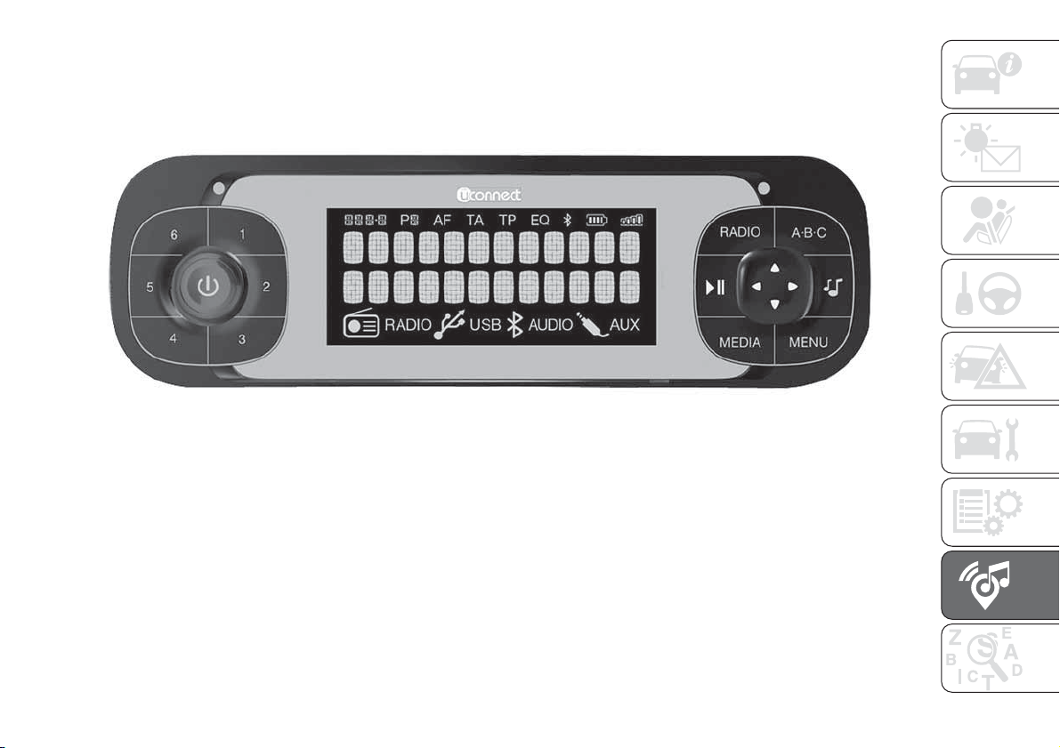
QUICK GUIDE
141
F1D0707
195
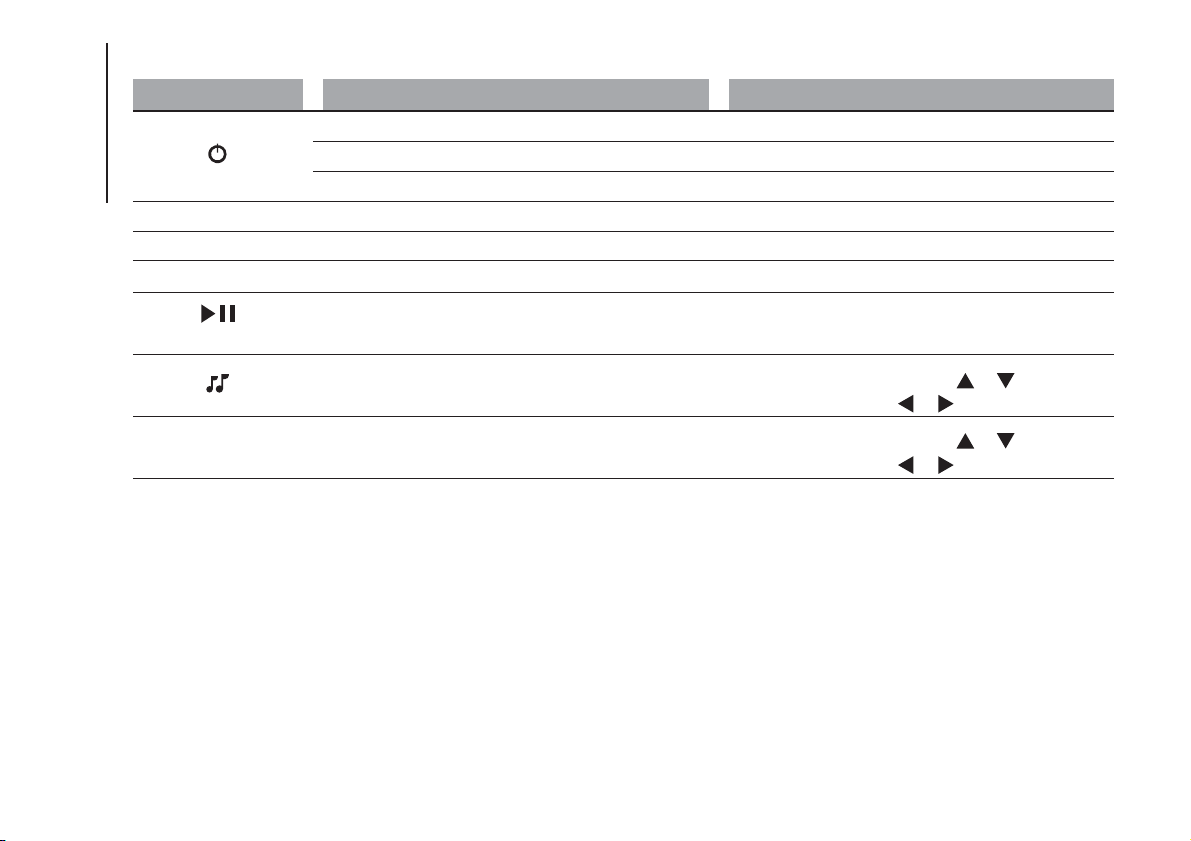
General functions
Button Functions Mode
Switching on short button press
Switching off long button press
Volume adjustment turn knob
RADIO Select the radio source FM, AM, DAB (where present) short cyclical button press
ABC–123456 Select preset ranges short cyclical button press
MEDIA
Select Audio
Bluetooth®, USB/iPod, AUX
short cyclical button press
(Play/Pause)
Activate Play/Pause for the Media source
Activate Mute for the Radio and AUX sources
Short button press
Audio adjustments: low tones (BASS), high tones
(TREBLE), RH/LH balance (BALANCE), front/rear
balance (FADER) (where provided)
Menu activation: short button press
Adjustment type selection: press
or buttons.
Value adjustment: press
or buttons.
MENU Advanced functions adjustment
Menu activation: short button press
Adjustment type selection: press
or buttons.
Value adjustment: press
or buttons.
196
MULTIMEDIA
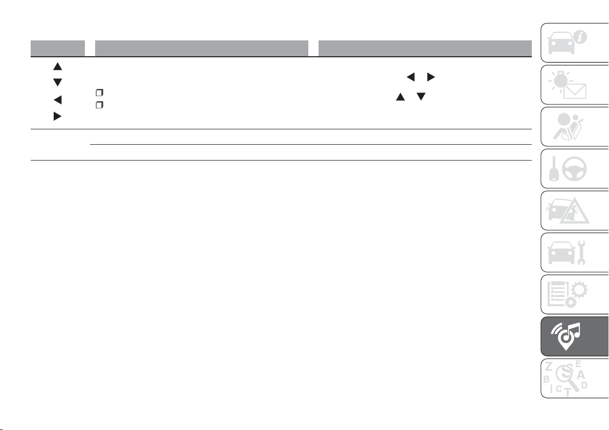
Radio functions
Button Functions Mode
Radio station search:
Automatic search
Manual search
Automatic search: press
or buttons (hold the button
down for fast forward)
Manual search: press
or buttons (hold the button
down for fast forward)
123456
Store current radio station Long button press for memory preset 1 to 6 respectively
Stored station recall Brief button press for memory preset from 1 to 6
197
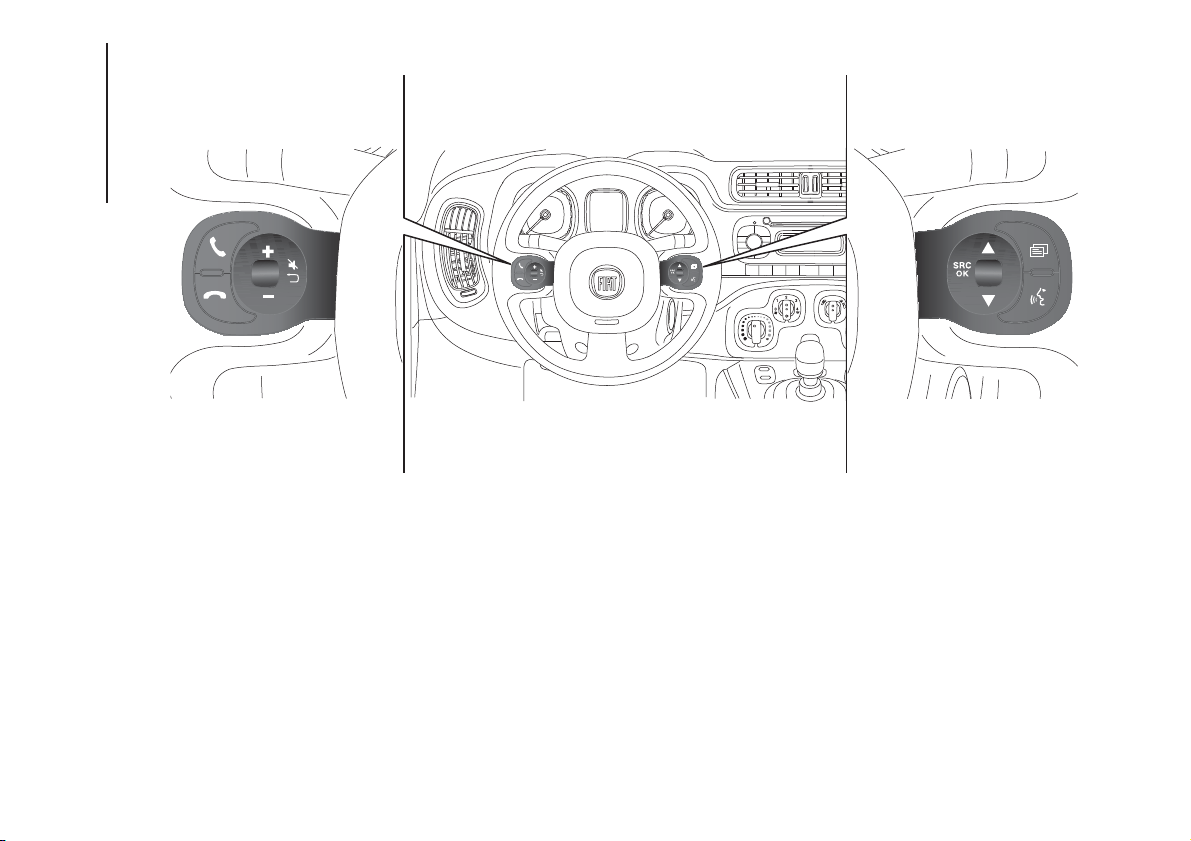
STEERING WHEEL CONTROLS
142
F1D0106
198
MULTIMEDIA
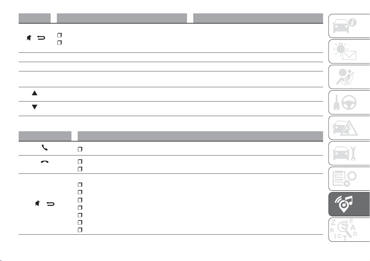
Button Functions Mode
/
Enable/disable Audio Mute
Return to the previous menu mode function
Short button press
+ Increasing volume Button press
– Decreasing volume Button press
SRC
Select sources FM, AM, DAB (where present),
Bluetooth®
Audio, USB and AUX
Button press
Radio: automatic search for the next tunable broadcaster -
USB/iPod source: selecting the next track
Button press
Radio: automatic search for the previous tunable
broadcaster - USB/iPod source: selecting the previous track
Button press
.
Multimedia support function
Button Functions
Accept an incoming phone call
End the phone call in progress
Reject an incoming phone call
/
Deactivate a voice recognition
Activate/deactivate Audio Mute
Interrupt the reading of an SMS message
Exit from the Main Menu of Bluetooth®
Exit from a submenu and return to previous menu option
Exit from the current menu option without saving
Deactivate/reactivate the microphone during a phone conversation
Mute the volume of the call tone for incoming phone calls
199
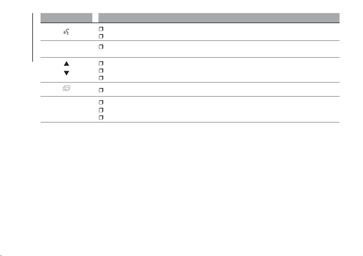
Button Functions
Activation of voice recognition
Interruption of the voice message in order to give a new voice command
+/-
Adjust the audio volume of all functions: hands-free, text message reader, multimedia supports, voice
messages, Radio, USB, depending on the active source.
Scroll through Menu items on the panel
Select multimedia support tracks
Scroll through SMS messages in the list
Access to the radio menu displayed on the instrument panel
SRC/OK
Confirm manually selected menu option
Select sources: FM, AM, DAB (where present), Bluetooth® AUDIO, USB and AUX
Select the SMS message on the instrument panel
The functions of the steering wheel controls are activated when the button is released.
200
MULTIMEDIA

GENERAL INFORMATION
The Uconnect Radio is equipped with
the following functions:
Radio section
PLL tuning with FM/AM/MW
frequency bands (where present);
RDS (Radio Data System) with TA
(traffic alerts) function - TP (traffic
programmes) - EON (Enhanced Other
Network) - REG (regional programmes);
AF: search selection for alternative
frequencies in RDS mode;
automatic/manual tuning into
stations;
FM Multipath detector;
manual storing of 36 or 54 stations:
18 in the FM band (6 in FM-A, 6 in
FM-B and 6 in FM-C) and 18 in AM (6
in AM-A, 6 in AM-B and 6 in AM-C) and
18 in DAB (where present);
SPEED VOLUME function:
automatic volume adjustment
according to the car speed;
automatic Stereo/Mono selection.
Audio section
Mute function;
Soft-Mute function;
Loudness function
7-band graphic equaliser;
Separate bass/treble adjustment
Right/left channel balance.
Bluetooth®
For the Bluetooth® function, see the
description in the dedicated paragraph.
USB/iPod section
For the USB/iPod function, see the
description in the dedicated paragraph.
AUX section
AUX source selection;
AUX Offset function: alignment of
the portable device volume with that of
the other sources;
Portable player playback.
NOTE It is not possible to view the AUX
source information on the radio display
FUNCTIONS AND
ADJUSTMENTS
Switching on
The Uconnect Radio comes on when
the
(ON/OFF) button/knob is
pressed briefly.
If the Uconnect Radio is switched on
when the key is removed from the
ignition, it will switch off automatically
after about 20 minutes (if this time
has been set). After the Uconnect
Radio has switched itself off
automatically it can be turned on for a
further 20 minutes by pressing the
(ON/OFF) button.
Switching off
Long press on button
(ON/OFF).
Volume adjustment
To adjust the volume, turn the twist
control
.
If the volume level is changed during
the transmission of traffic news, the
new setting will only be maintained until
the news is finished.
Mute Function
(muting the volume)
Press the
/ button on the
steering wheel to activate the Mute
function. In the Radio source, the word
“MUTE” will appear, associated with
the active source.
Press the
/ button on the
steering wheel again to deactivate the
Mute function.
Audio settings
The functions that can be selected from
the audio menu change depending on
the context: AM/FM and DAB (where
present)/USB/iPod/Bluetooth®/AUX.
Press the AUDIO button briefly to
change the Audio functions. After the
AUDIO button is first pressed, the
display will show the bass level value
for the source activated at that time
(e.g. in FM mode the display will show
the wording "FM Bass +2").
201
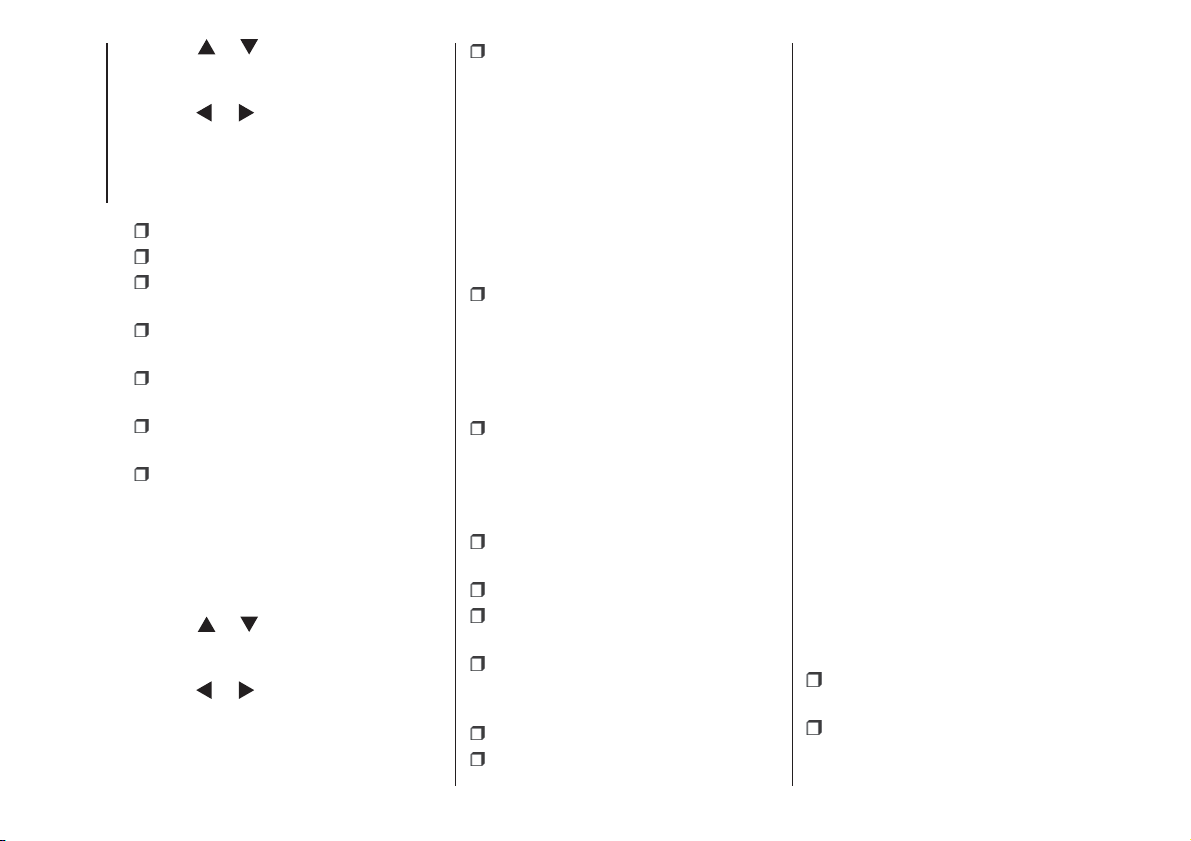
Use the or buttons to scroll
through the menu functions. To change
the setting of the function selected
use the
or buttons.
The current status of the selected
function appears on the display.
The functions managed by the Menu
are:
BASS: adjustment of bass tones;
TREBLE: adjustment of high tones;
BALANCE: right/left balance
adjustment;
FADER: front/back balance
adjustment (where provided);
LOUDNESS: activation/deactivation
of the increase of bass and high tones;
EQUALISER: activation and
selection of factory-set equaliser levels;
MY EQ: customised equaliser
setting.
MENU
MENU button functions
Press the button MENU briefly to
activate the Menu function.
Use the
or buttons to scroll
through the menu functions. To change
the setting of the function selected
use the
or buttons.
The functions managed by the Menu
are:
AF SWITCHING: automatic
activation/deactivation of the selection
of the station with the strongest signal
that transmits the same programme.
NOTE FM following in DAB (where
provided; the radio switches
automatically to FM in case of low DAB
signal and back to DAB as soon as
the signal is available) is enabled by
enabling AF.
TRAFFIC INFORMATION: activation/
deactivation of traffic information.
NOTE Traffic information is enabled only
if tuned to the station broadcasting
the announcement.
DAB INFO CATEGORIES (only
enabled for DAB sources): single
category enable/disable (Financial,
News flash, Program info, Spec event,
Sport report, Warning, Weather).
REGIONAL MODE: activation/
deactivation of regional programmes.
MP3 DISPLAY: MP3 display setting.
SPEED VOLUME: speed-dependent
automatic volume control.
RADIO ON VOLUME: maximum
radio volume limit activation/
deactivation.
RADIO OFF: off mode selection.
SYSTEM RESET: reset of factory
settings.
Press the button MENU again to exit
the Menu function.
NOTE The AF SWITCHING, TRAFFIC
INFORMATION and REGIONAL MODE
adjustments are only possible in FM
mode.
RADIO (Tuner)
To select the Radio function while
listening to another audio source, briefly
press the RADIO button several times
to select the desired band, FM AM
or DAB (where present).
Once the Radio mode has been
activated, the display will show the
name (only RDS stations) and the
frequency of the selected radio station,
the frequency band selected (e.g.
FMA) and the preselect button number
(e.g. P1).
Each time the button is pressed, the
FM, AM and DAB bands (where
present) are selected cyclically.
Preset buttons
The buttons numbered from 1 to 6 are
used to set the following preset
stations:
18 in the FM band (6 in FM-A, 6 in
FM-B and 6 in FM-C);
18 in the AM band (6 in AM-A, 6 in
AM-B and 6 in AM-C).
202
MULTIMEDIA
To listen to a preset station, select the
desired frequency band with the RADIO
button, briefly press ABC button to
select the preset band (A, B or C), and
then briefly press the corresponding
preset button (from 1 to 6).
By pressing the preset button for more
than 2 seconds, the tuned station will
be stored. The storing phase is
confirmed by an acoustic signal.
Automatic tuning
Briefly press the
or button to start
the automatic tuning search for the
next station that can be received in the
selected direction.
Manual tuning
Select the desired frequency band and
then press the
or button briefly
and repeatedly to start to the search in
the desired direction. If the
or
button is pressed longer, the fast
search will start and then stop when the
button is released.
USB/iPod MODE
To activate USB/iPod mode, insert the
respective device (USB stick or other
device) in the USB port located in
the glove compartment.
If a USB/iPod device is inserted with
the system on, this starts playing the
tracks present on the device.
AUX MODE
To activate the AUX source, press the
MEDIA button or the SRC control
on the steering wheel repeatedly until
the corresponding source is displayed.
BLUETOOTH®
Bluetooth® technology allows you to
use your mobile phone through the
car's hands-free system, without the
need for wires.
To use the hands-free function it is
necessary to have a mobile phone with
Bluetooth® technology. To consult the
list of compatible phones, see the site:
www.mopar.eu/owner.
The hands-free function allows the
following operations to be performed:
Calling a telephone number by voice
command: you can dial a telephone
number by stating the numbers out
loud.
Calling someone in the phonebook
using voice commands: you can call
someone in your mobile phonebook
using your voice. You can also call
someone in your phonebook by
selecting from the contacts that appear
on the display of the instrument panel.
(This function requires your phone
directory to have been copied onto the
car hands-free system).
Accepting a call: you can accept an
incoming call by pressing the
button
on the steering wheel.
Rejecting a call: you can reject a call
with a long press of the
button on
the steering wheel.
Text message reader
(available only with mobile phones that
support this function)
The SMS message reader makes it
possible to:
Be informed, by means of a
message on the instrument panel
display, of the reception a new SMS
message on your mobile phone with
Bluetooth® technology; the number/
name of the sender is displayed and
the system will also ask whether to read
the message to you.
Manage the list of messages
received on your mobile phone only
during connection with the active
system.
Quick guide to the SMS message
reader
(only for mobile phones that support
this function)
If your Bluetooth® phone supports
this function, when you receive a new
SMS message, the system alerts you
with an acoustic signal and asks you if
you want to read it.
203
Say “Yes” or press the button or
SRC/OK. The system will read the
last message received;
Say “NO” or press the /
button. The system will store the
message which you can read later, as
long as the phone is connected to
the system.
To get to know all the functions and
ways of using the SMS message
reader, refer to the "SMS MESSAGE
READER FUNCTIONS" chapter.
MULTIMEDIA FUNCTIONS
The MEDIA menu allows you to view
and reproduce the tracks stored on a
USB/Bluetooth® AUDIO or AUX
source (connected to the USB port).
It is recommended to load only
unprotected music files, with supported
extensions. If the USB device contains
other formats (e.g. .exe, .cab, .inf,
etc.), problems might arise during
playing of tracks.
To connect your UBS device to the
system, proceed as follows:
Connect the device to the USB
socket in the glove compartment;
Turn the ignition key to MAR. The
system will automatically start playing
your digital tracks, selecting them from
a library that is created the moment
the USB device is connected.
When the creation of the multimedia
library is over, it is possible to use
the system to display and select the
tracks present and to activate playing.
Managing the multimedia library
With the MEDIA function you can select
the digital audio on your USB device,
using voice recognition or the steering
wheel controls.
Tracks may be selected by folder, artist,
musical genre, album and playlist.
Activate the Main Menu from the
steering wheel controls on the
instrument panel display, select the
BROWSE USB option and then press
SRC/OK.
Select one of the following items:
FOLDERS
ARTISTS
GENRES
ALBUMS
PLAYLIST
and press SRC/OK.
select “PLAY ALL” and confirm with
SRC/OK;
select the item chosen and confirm
with SRC/OK;
It is also possible to access the same
functions with the voice commands:
press the button on the steering
wheel
and say "BROWSE USB";
say one of the available options:
"FOLDERS", "ARTISTS", "GENRES",
"ALBUMS", "PLAYLIST";
select “PLAY ALL” and confirm with
SRC/OK;
select the item chosen and confirm
with SRC/OK.
Pause
To pause the track you are listening to:
press the
button on the front
panel of the Uconnect Radio.
To resume listening to a track that you
have paused: press the
button
on the front panel of the Uconnect
Radio.
Stop
To stop playing a track: say "Stop”.
To resume, say “Play”.
NOTE The “Play” command is only
available if playback has been stopped
using the “Stop” command.
Next track
To skip to the next track, using manual
interaction: while listening to a digital
track, press
(steering wheel controls)
or
(Uconnect Radio controls) (where
present).
204
MULTIMEDIA
Previous track
To return to the previous track, using
manual interaction: while listening to a
digital track, press (steering wheel
controls) or
(Uconnect Radio
controls) (where present).
Change audio source
To change the active audio source
(Radio, USB/iPod, Tuner, Bluetooth®
Audio) press the SRC/OK or MEDIA
button on the front panel of the Ucon-
nect Radio, or, with voice interaction:
say “Select source USB/iPod, Radio,
Bluetooth® Audio”.
NOTE While playing Bluetooth® audio,
there could be some incorrect displays
related to the phone. This is not due to
the radio, but depends on the informa-
tion sent by the phone.
BLUETOOTH® DEVICE
IMPORTANT NOTES
Access to the phonebook copied
onto the system is possible only when
the mobile phone from which it has
been copied is connected.
The names stored on the SIM card
or in your mobile phone memory can
be transferred to the system in different
ways, depending on the model of
mobile phone.
Getting to know the voice
commands
When talking to the system, you can
always use the voice command "Help"
to obtain detailed instructions on the
voice commands available for each
interactive stage.
Pairing a Bluetooth® device
NOTE This operation should be carried
out only with the car stationary.
To pair your mobile phone with the
system, proceed as follows.
Manual procedure:
Activate the Main Menu by pressing
the MENU button;
select the SETTINGS option, then
the "Pairing" option.
Voice procedure:
Press and say “Settings”. Then,
at the end of the message, say
"Pairing".
The system will show a PIN number
on the display to be used for pairing.
Using the search function of the Blu-
etooth® devices of your phone, search
for the “Radio BT” device.
When prompted, enter the PIN code
displayed on the instrument panel
using your mobile phone keypad. If
pairing is successful, the system will
say "Connecting" and at the end the
display will show, as confirmation, the
ID of the paired mobile phone.
Once the device has been paired, if the
function is supported by the phone,
the system automatically asks to
download the phonebook onto the
Uconnect Radio.
NOTE After updating the phone
software, for proper operation, it is
recommended to remove the phone
from the list of devices linked to the
radio, delete the previous system
pairing also from the list of Bluetooth®
devices on the phone and make a new
pairing.
Making a phone call
Press the steering wheel control
and say “Call” and the name of the
contact in the phonebook.
If the name is recognised, the
system will display the information for
the contact on the display.
The system will ask you to confirm
your request. To make the call, say
"Yes"; otherwise, say "No".
205
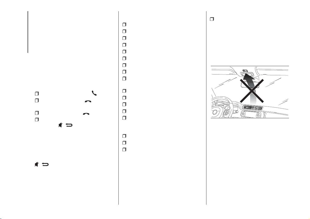
Alternatively, it is possible to call a
number that is not in the phonebook by
saying the number one figure at a
time.
Managing an incoming call
When a call is received, the system will
display the caller's ID, where available.
The incoming call will be signalled by
your mobile phone's personalised
ringtones (the availability of this function
depends on the specific features of
your phone).
Answering a call:
To answer the call, press ;
To end the call, press for more
than 1 second.
To reject a call: press
To ignore a call and not hear the ring
tone, press
/ .
Putting a phone call on HOLD
To place a call in progress on HOLD
and disable the microphone in order to
be able to speak without being heard
by the person you are talking to, press
/ .
VOICE COMMANDS
Global commands
SELECT MEDIA SOURCE;
SELECT RADIO SOURCE;
SELECT PHONE SOURCE;
CALL or DIAL;
READ MESSAGE;
SETTINGS;
HELP;
CANCEL;
REPEAT.
Phone commands
DIAL;
CALL (followed by name);
CALL (followed by number);
CALL BACK;
READ LAST;
Audio Bluetooth®/USB/iPod Com-
mands
PLAY;
PAUSE;
STOP.
Radio
SELECT BAND “FM” “AM” or
“DAB”.
NOTE It is advisable not to direct the
middle air vents towards the
microphone (fig. 143) because the
noise generated by the air on the
microphone could cause worsen voice
control performance.
PANDA UCONNECT APP
To use the Panda Uconnect app you
must download it from the Apple App
Store or from Google Play and pair
the smartphone to the radio via Blu-
etooth®, as described in the "Blu-
etooth® Device” chapter. For the list of
compatible phones, see Fiat elum site.
The app interface may change
depending on how it is used:
connected or not connected to the car
radio.
143
F1D0999
206
MULTIMEDIA
When it is connected via Blu-
etooth®, you can interact with the
radio through the screen of your smart-
phone. You can listen to you favourite
music by selecting the source, the track
or the radio station desired. You can
also view the phonebook, your car
handbook and, if necessary, call for
assistance.
When it is not connected, you can
have all the information about the state
of your car with my:Car and indications
about your driving style with eco:Drive.
You can also find your car easily if
you do not remember where you
parked it.
WARNING
187) If the volume is too loud this could be
dangerous for the driver and for
passengers when driving in traffic. Always
adjust the volume so that you can still
hear background noises.
188) The use of some of the system's
features whilst driving can divert attention
away from the road, with the risk of
causing accidents or other serious
consequences; therefore they must only be
used when the driving conditions allow
and, where necessary, only when the car is
stationary.
189) Read and follow these instructions:
before using your system, read and follow
all the safety information and instructions in
this manual. Failure to observe the
precautions found in this manual may lead
to an accident or other serious
consequences.
190) Keep the manual in the car: if it is kept
in the car, the manual will become
something quick and easy to consult for
those not familiar with the system. Ensure
that everyone has access to the manual
and reads the instructions and the safety
information carefully before using the
system for the first time.
191) Warning: looking at the system when
driving can divert attention from the road,
with the risk of accidents or other serious
consequences. Do not change system
settings or enter data non-verbally (using
the manual controls) while driving. Stop the
vehicle in a safe and legal manner before
carrying out these operations. Adopting
these precautions is important since setting
or changing some functions might require
the driver to be distracted away from
the road and remove his or her hands from
the steering wheel.
192) Voice commands: the system
functions can be carried out using only
voice commands. The use of voice
commands when driving allows you to
manage the system without taking your
hands off the steering wheel.
193) Looking at the display for a long time:
while driving, do not use any function
that requires looking at the display for a
long time. Pull over in a safe and legal
manner before attempting to access a
function of the system that requires
prolonged attention. Even occasional quick
glances at the display can be dangerous
if the driver's attention is diverted at a
critical moment.
194) Setting the volume: do not turn the
volume up too high. When driving, keep the
volume at a level that allows you to hear
the traffic outside and emergency sirens.
Driving while unable to hear these sounds
may cause an accident.
195) Using the voice recognition: the voice
recognition software is based on a
statistical process that is subject to error. It
is your responsibility to monitor voice
recognition functions included in the
system and address any errors.
196) Danger of distraction: the functions
may require manual settings (not using
voice commands). Attempting to perform
such setup or insert data while driving
can seriously distract your attention and
could cause an accident or other serious
consequences. Stop the vehicle in a safe
and legal manner before carrying out these
operations.
207

RADIO EQUIPMENT
DIRECTIVE
2014/53/EU
All radio equipment supplied with the
vehicle complies with the 2014/53/EU
directive. For further information visit the
websites www.mopar.eu/owner or
http://aftersales.fiat.com/elum/
208
MULTIMEDIA
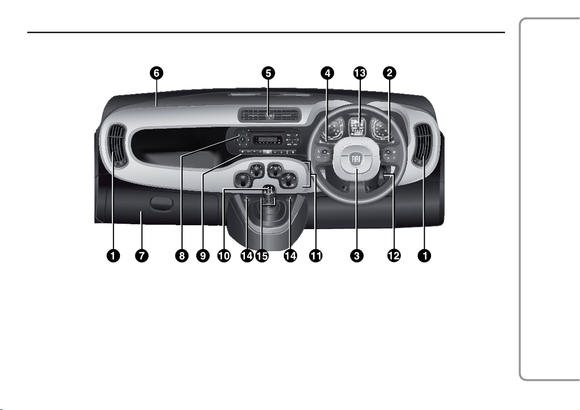
209
The presence and position of controls, instruments and gauges may vary depending on the versions.
1. Adjustable and directable air diffusers 2. Exterior light control stalk 3. Driver front airbag 4. Windscreen wiper/rear window wiper/trip computer
control lever 5. Adjustable and directable centre air vents 6. Passenger front airbag 7. Glove compartment (for versions/markets, where provided)
8. Radio (for versions/markets, where provided) 9. Control buttons 10. Gear lever 11. Heating/ventilation/climate control system controls 12. Ignition
device 13. Instrument panel 14. Electric front windows 15. ECO/ASR OFF buttons (for versions/markets, where provided)
144
F0W0476
DASHBOARD (RIGHT-HAND DRIVE VERSION)
RIGHT HAND DRIVE VERSIONS
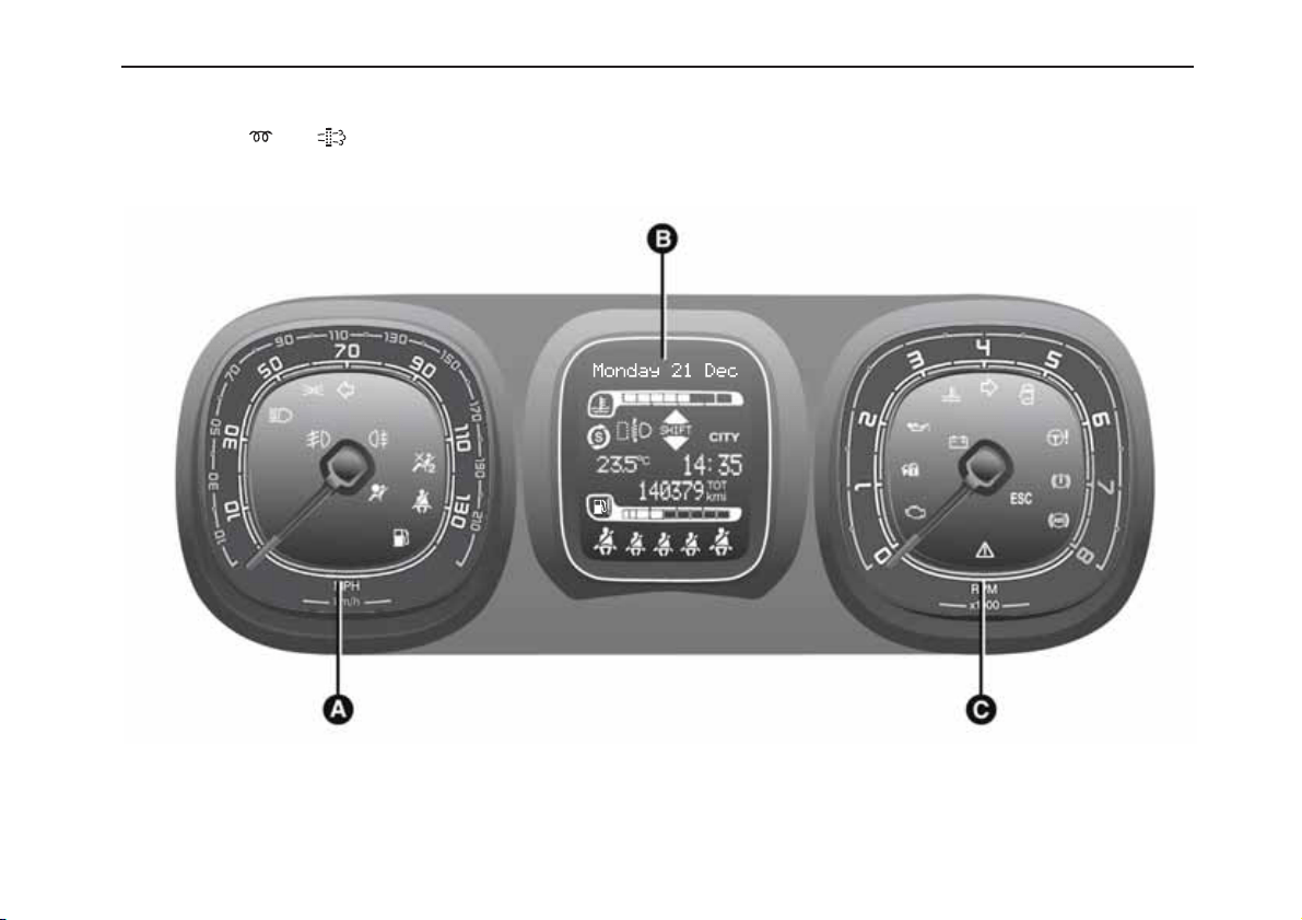
210
The instrument background colour and type may vary according to the versions.
The warning lights on the instrument panel may change according to the version/trim level (e.g. LPG, Cross etc.) of the vehicle.
Warning lights
and are available on diesel versions only. On diesel versions, the maximum engine speed (red range on
the rev counter) corresponds to 6000 rpm.
A. Speedometer (speed indicator) – B. Multifunction display – C. Rev counter
145
F1D0692
CONTROL PANEL AND ON-BOARD INSTRUMENTS
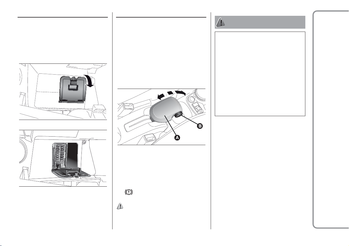
211
Fuse box on the dashboard
To access the fuses, remove the plastic
cover fig. 146. The fuses are in the
fuse box shown in fig. 147.
Switch off the engine and engage the
parking brake. Engage a gear (first gear
if the car is parked facing uphill or
reverse if facing downhill) and leave the
wheels turned. If the vehicle is parked
on a steep slope, block the wheels with
a wedge or stone. Always remove the
ignition key when leaving the car.
To engage the handbrake, pull the lever
A fig. 148 upwards until the car cannot
be moved. To disengage the
handbrake, slightly raise lever A and
hold button B pressed, checking that
the
warning light switches off in the
instrument panel.
119) 120) 121)
WARNING
197) Never leave children unattended in
the car. Always remove the key from the
ignition when leaving the car and take
it with you.
198) The car should be braked after a few
clicks of the lever, if it is not, contact a
Fiat Dealership to have it adjusted.
199) In the case of parking manoeuvres on
roads on a gradient, the front wheels
must be steered towards the pavement
(when parking downhill), or in the opposite
direction if the vehicle is parked uphill.
Block the wheels with a wedge or a stone if
the car is parked on a steep slope.
146
F0W0294
147
F0W0295
148
F0W0296
REPLACING FUSES
Fuse location
PARKING
PARKING BRAKE
RIGHT HAND DRIVE VERSIONS

WARNING
INTERIOR FITTINGS
Never travel with the glove compartment open: it could injure the passenger in the event of a crash.
The cigar lighter gets very hot. Handle it carefully and make sure that children do not touch it: risk of fire and/or burns. Always check that
the cigar lighter plug has been released.
ROOF RACK/SKI RACK
After travelling for a short distance, check that the fixing screws for the attachments are correctly tightened.
Never exceed the maximum permitted loads (see chapter "Technical specifications").
Evenly distribute the load and take into account, when driving, the increased responsiveness of the vehicle to side wind.
WIRING FOR RADIO SYSTEM
If you wish to have a sound system installed after purchasing the vehicle, first contact a Fiat Dealership whose qualified personnel will give
you advise about a sound system that does not damage the battery charge. Excessive nonrunning consumption damages the battery and
may cause your battery warranty to be terminated.
PROTECTING THE ENVIRONMENT
During normal service, the catalytic converter and the diesel particulate filter (DPF) reach high temperatures. Do not therefore park the
vehicle over inflammable materials (grass, dry leaves, pine needles, etc.): fire hazard.
INTERIORS
Never use flammable products, such as petrol ether or rectified petrol to clean the inside of the vehicle. The electrostatic charges which
are generated by rubbing during the cleaning operation may cause a fire.
Do not keep aerosol cans in the vehicle: they might explode. Aerosol cans must not be exposed to a temperature exceeding 50°C. When
the vehicle is exposed to sunlight, the internal temperature can greatly exceed this value.
POWER SUPPLY
Modifications or repairs to the supply system that are not carried out correctly or do not take the system technical specifications into
account can cause malfunctions leading to the risk of fire.
LOADING ADVICE (Panda VAN versions)
Abrupt braking or occasional impacts may cause sudden movements of the load with consequent situations of hazard for the driver and
passengers: before setting off, secure the load tightly using the partition and, where provided, the appropriate hooks. For securing use
cables, ropes or belts strong enough to hold the items to be secured.
212
WARNING
ROOF RACK/SKI RACK
Fully comply with the regulations in force concerning maximum clearance.
WIRING FOR RADIO SYSTEM
For connection to the radio system set-up, contact a Fiat Dealership to prevent any problem that could impair vehicle safety.
BODYWORK
In order to preserve the aesthetic appearance of the paint abrasive products and/or polishes should not be used for cleaning the vehicle.
Avoid washing with rollers and/or brushes in washing stations. Wash the vehicle only by hand using neutral pH detergents; dry it with a wet
chamois leather. Abrasive products and/or polishes should not be used for cleaning the vehicle. Bird droppings must be washed off
immediately and thoroughly as the acid they contain is particularly aggressive. Avoid (if at all possible) parking the vehicle under trees; remove
vegetable resins immediately as, when dried, it may only be possible to remove them with abrasive products and/or polishes, which is highly
inadvisable as they could alter the typical opaqueness of the paint. Do not use pure screen washer fluid for cleaning the windscreen and
rear window; dilute it min. 50% with water. Only use pure screen washer fluid when strictly necessary due to outside temperature conditions.
INTERIORS
Never use alcohol, petrols and derivatives to clean the dashboard and instrument panel lens.
WARNING
BODYWORK
Detergents pollute the environment. Only wash your vehicle in areas equipped to collect and treat wastewater from this type of activity.
213
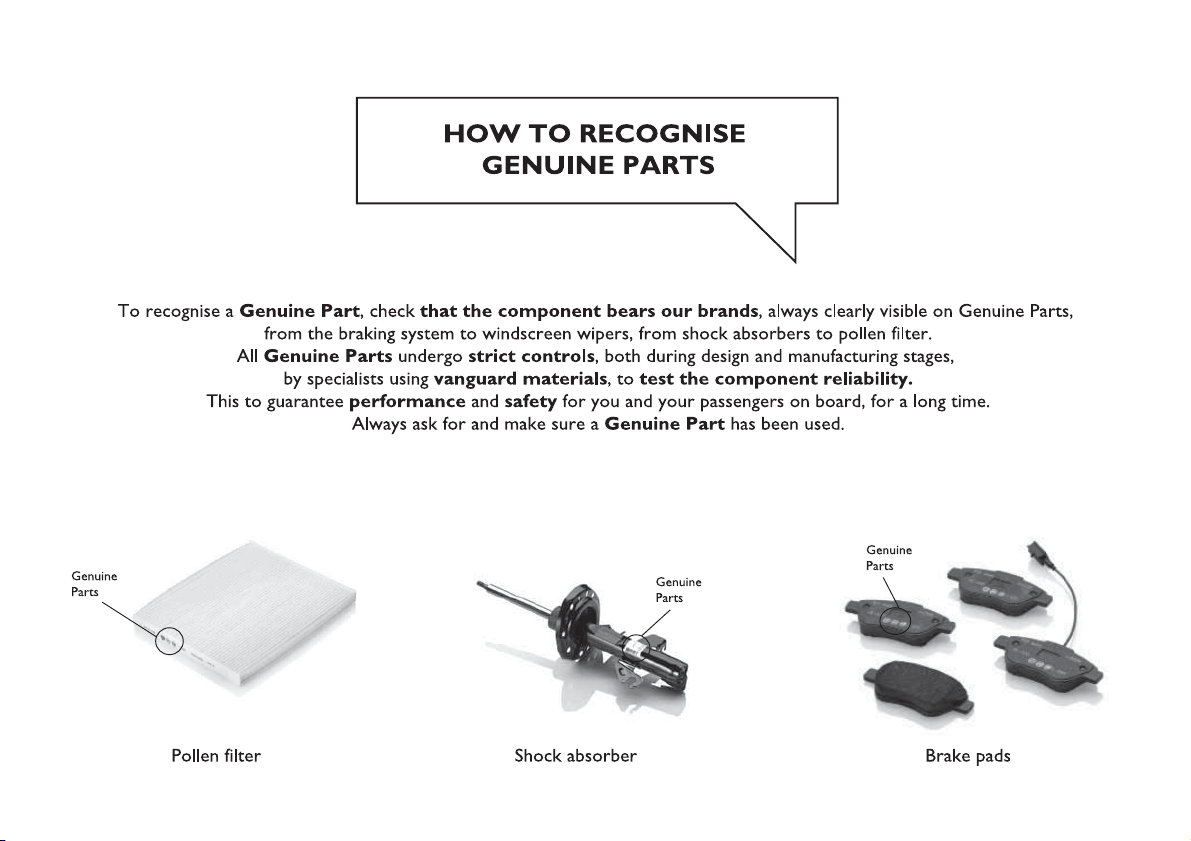

Mopar Vehicle Protection offers a series of service contracts that are designed to give all our customers the
pleasure of driving their vehicle without any hitch's and concerns.
Our product portfolio consists of a wide and flexible range of extended warranty and maintenance plans
endorsed by FCA. Each with a series of different coverage tiers, in terms of durability and mileage, built to
accommodate you’re driving needs.
Service contracts are made by experts that know every part of your vehicle, and commit themselves
to maintain it in tip top conditions. Our knowledge and passion is tailored around designing
products that promises all our drivers “worry-free driving”.
Only with Mopar Vehicle Protection you are ensured that all service operations are performed
by highly qualified and specialized technicians in authorized FCA repair facilities, using the right tools,
equipment and only original parts, all over Europe.
Check which Service Contract plans are available on your market today and choose the
Service Contract that suits your driving habits best.
Ask your local dealer for further information.
MAINTAIN YOUR VEHICLE IN
TIP TOP CONDITIONS WITH
INDEX
A
BS (system)
.......................58
Active safety systems................58
Airbag ..............................83
ASR (system) .......................59
Battery
recharging .....................137
Bonnet .............................25
Boot ................................27
Brakes
mechanical wear detector ......144
CBC system
.......................64
Checking levels ...................
.139
Child protection systems.............73
Cleaning and maintenance
bodywork ......................146
car interior .....................147
Climate control system ..............21
CO2 emissions ....................181
Control panel and on-board
instruments ..................36-210
Dashboard
..........................8
Daytime running lights (DRL)
"Daytime Running Lights" .........17
Dimensions ........................163
Dipped headlights
control ...........................17
Dipped/main beam headlights
(bulb replacement) ...............108
Direction indicators
control ...........................17
Direction indicators (changing a
bulb) ............................108
Display .............................37
Doors...............................11
door locking/unlocking ...........11
Driving assistance systems ..........64
D.R.L. (daytime running lights) .......17
Dualdrive electric power steering..................................96
Dualogic transmission ...............94
ECO function
.......................97
Electric windows ....................25
Engine.............................150
Engine compartment ...............139
ESC (system) .......................58
Exterior lights .......................16
Fiat CODE (system)
.................10
Fix&Go kit .........................118
Fluids and lubricants ...............175
Fog lights (bulb replacement) .......109
Follow me home (device) ............17
Front airbags........................83
Front ceiling light ....................18
Front/rear fog lights..................18
Fuel consumption ..................179
Fuel cut-off system.................122
Fuses (replacement)................112
Gear Shift Indicator
.................37
Handbrake
.........................92
Hazard warning lights ..............106
HBA (system) .......................59
Head restraints......................14
HH (system).........................58
Ignition device
......................10
Important information and
recommendations ...............212
Instrument panel ...................209
Interior lights ........................18
Interiors (cleaning)..................147
iTPMS ..............................65
Jump starting
.....................121
Keys
................................9
key with remote control ............9
Mechanical key ....................9
Lifting the vehicle
..................145
Main beam headlights
control ...........................17
Manual transmission.................93
Mode selector.......................95
Number plate lights (bulb
replacement)
....................111
Occupant protection systems
.......68
Official type approvals ..............208
Parking lights
.......................17
Parking sensors .....................99
Performance (top speed) ...........178
Pre-tensioners ......................71

Prescriptions for handling the
vehicle at the end of its life .......183
Radio
.............................185
Rear fog lights.......................18
Rear light clusters (changing a
bulb) ............................110
Rear view mirrors....................15
Rear window washer nozzles .......145
Refuelling ..........................173
Refuelling the vehicle ...............100
Replacing a bulb ...................106
Reversing light/rear fog light ........110
SBR (Seat Belt Reminder)
system
...........................70
Scheduled maintenance............126
Seat belts...........................68
Seats ...............................12
adjustments .....................12
Side airbags ........................87
Side lights/daytime running lights
(bulb replacement) ...............110
Smartphone Docking ................29
Snow chains.......................154
Start&Stop system ..................98
Starting the engine ..................91
Steering lock ........................10
Steering wheel ......................15
Steering wheel stalks
left stalk .........................16
right stalk ........................19
Supplementary Restraint System
(SRS) - Airbag ....................83
Symbols .............................3
Technical data
....................149
Third brake light (bulb
replacement) ....................111
Towing the car .....................123
Towing trailers .....................103
Uconnect Radio
...................193
USB ports and AUX input ............28
Version with LPG system
............30
Version with methane system
(Natural Power) ...................32
Warning lights on panel
.............39
Weights ...........................166
Wheel (changing)...................115
Wheels and tyres ..............146-154
When parked .......................92
Window washing ....................19
Windscreen washer nozzles ........145
Windscreen/rear window wiper .....144
INDEX
FCA Italy S.p.A. - MOPAR - Technical Services - Service Engineering
Largo Senatore G. Agnelli, 3 - 10040 Volvera - Turin (Italy)
Print no. 603.91.374 - 06/2017- 2 Edition

We really know your car because we invented, designed and built it: we really know every single detail.
At Fiat Service authorised workshops you can find technicians directly trained by us,
offering quality and professionalism for all service operations.
Fiat workshops are always close to you for the regular servicing operations, season checks
and practical recommendations by our experts.
With Original Parts distributed by MOPAR
®
, you maintain the reliability, comfort
and performance features that you bought your new car for over time.
Always ask for Genuine Parts for the components used on our cars; we recommend them because
they come from our steady commitment in research and development of highly innovative technologies.
For all these reasons: rely on Genuine Parts, because they are the only ones designed
by FCA for your car.
SAFETY:
BRAKING SYSTEM
ENVIRONMENT: PARTICULATE FILTERS,
CLIMATE CONTROL MAINTENANCE
COMFORT: SUSPENSION
AND WINDSCREEN WIPERS
PERFORMANCE: SPARK PLUGS,
INJECTORS AND BATTERIES
LINEACCESSORI
ROOF RACK BARS, WHEEL RIMS
WHY CHOOSING
GENUINE PARTS

The data contained in this publication is intended merely as a guide. FCA Italy S.p.A. reserves the right to modify
the models and versions described in this booklet at any time for technical and commercial reasons.
If you have any further questions please consult your FIAT dealer.
Printed in recycled paper without chlorine.
ENGLISH