
2020
FIAT
®
124 SPIDER
FIAT
®
124 SPIDER
2020
OWNER'S MANUAL
Printed in U.S.A.
20_BA_OM_EN_USC
124 Spider
First Edition
Owner’s Manual
©2019 FCA US LLC. All Rights Reserved.
FIAT is a registered trademark of FCA Group Marketing S.p.A., used under license by FCA US LLC. App
Store is a registered trademark of Apple Inc. Google Play Store is a registered trademark of Google.

INSTALLATION OF RADIO TRANSMITTING
EQUIPMENT
Special design considerations are incorporated into this
vehicle’s electronic system to provide immunity to radio
frequency signals. Mobile two-way radios and telephone
equipment must be installed properly by trained person-
nel. The following must be observed during installation.
The positive power connection should be made
directly to the baery and fused as close to the baery as
possible. The negative power connection should be made
to body sheet metal adjacent to the negative baery
connection. This connection should not be fused.
Antennas for two-way radios should be mounted on
the roof or the rear area of the vehicle. Care should be
used in mounting antennas with magnet bases. Magnets
may aect the accuracy or operation of the compass on
vehicles so equipped.
The antenna cable should be as short as practical and
routed away from the vehicle wiring when possible. Use
only fully shielded coaxial cable.
Carefully match the antenna and cable to the radio to
ensure a low Standing Wave Ratio (SWR).
Mobile radio equipment with output power greater than
normal may require special precautions.
All installations should be checked for possible
interference between the communications equipment
and the vehicle’s electronic systems.
Operating, servicing and maintaining a
passenger vehicle or o-highway motor
vehicle can expose you to chemicals inclu-
ding engine exhaust, carbon monoxide,
phthalates, and lead, which are known to
the State of California to cause cancer and
birth defects or other reproductive harm.
To minimize exposure, avoid breathing
exhaust, do not idle the engine except as ne-
cessary, service your vehicle in a well-ven-
tilated area and wear gloves or wash
your hands frequently when servicing
your vehicle. For more information go to
www.P65Warnings.ca.gov/passenger-vehicle.
WARNING:
VEHICLES SOLD IN CANADA
With respect to any vehicles sold in Canada, the name
FCA US LLC shall be deemed to be deleted and the
name FCA Canada Inc. used in substitution therefore.
DRIVING AND ALCOHOL
Drunken driving is one of the most frequent causes of
accidents.
Your driving ability can be seriously impaired with
blood alcohol levels far below the legal minimum. If
you are drinking, do not drive. Ride with a designated
non-drinking driver, call a cab, a friend, or use public
transportation.
This manual illustrates and describes the operation
of features and equipment that are either standard or
optional on this vehicle. This manual may also include
a description of features and equipment that are no
longer available or were not ordered on this vehicle.
Please disregard any features and equipment described
in this manual that are not on this vehicle.
FCA US LLC reserves the right to make changes in
design and specications, and/or make additions to
or improvements to its products without imposing
any obligation upon itself to install them on products
previously manufactured.
Driving after drinking can lead to an accident.
Your perceptions are less sharp, your reexes are
slower, and your judgment is impaired when you
have been drinking. Never drink and then drive.
WARNING!
Copyright © 2019 FCA US LLC

1
20_BA_OM_EN_USC
DEAR CUSTOMER
Dear Customer,
We would like to congratulate and thank you
for choosing a Fiat 124 Spider.
We have written this Owner’s Manual to help
yo
u get to know all the features of your
vehicle and use it in the best possible way.
Here you will find information, advice and
im
portant warnings regarding use of your
vehicle, and how to achieve the best perfor
-
mance from the technical features of your
ve
hicle.
You are advised to take the time to read
th
ese publications carefully before taking to
the road for the first time, in order to become
familiar with the controls, specifically those
concerning brakes, steering and transmis
-
sion; at the same time, you can understand
th
e vehicle behavior on different road
surfaces.
This document also provides a description of
sp
ecial features and tips, as well as essential
information for the safe driving, care, and
maintenance of your vehicle over time.
In the additional Warranty information avail-
able online, you will also find a description of
th
e services that FCA US LLC offers to its
customers, and the detail of the terms and
conditions for maintaining its validity.
We are sure that these will help you to get in
to
uch with and appreciate your new vehicle
and the service provided by the people at
FCA US LLC.
Enjoy reading and happy motoring!
NOTE:
This Owner’s Manual describes all models of
th
e vehicle; please consider only the infor-
mation relevant to your vehicle’s trim level,
e
n
gine and model. All data contained in this
publication are purely indicative. FCA US
LLC can modify the vehicle model described
in this publication at any time, for technical
or commercial purposes. For further informa
-
tion, contact an authorized dealer.

2
READ THIS CAREFULLY
REFUELING
Only refuel with unleaded gasoline
with a recommended rating of 91
oc
tane. A rating less than 87
octane is not acceptable. Do not
use gasoline containing methanol or ethanol
E85. Using these mixtures may cause
misfiring and handling issues, as well as
damage fundamental components of the fuel
supply system.
STARTING THE ENGINE
If equipped with a manual transmis-
sion: Be sure that the parking brake
i
s engaged; place the gear selector
in NEUTRAL, fully depress the
clutch pedal without pressing the acceler
-
ator, and then push the ignition button. The
en
gine will start as soon as the ignition is
pushed.
If equipped with an automatic transmission: B
e
sure that the parking brake is engaged and
that the gear selector is in PARK (P) or
NEUTRAL (N), depress the brake pedal, and
then push the ignition button. The engine
will start as soon as the ignition is pushed.
PARKING ON FLAMMABLE
MATERIAL
The catalytic converter develops
high temperatures during opera-
tion. Do not park the vehicle on
p
o
tential fire hazards such as:
grass, dry leaves, pine needles or other flam
-
mable materials.
RESPECTING THE
ENVIRONMENT
The vehicle is equipped with a
system that carries out a contin-
uous diagnosis of the emis-
sion-related components in order to
h
e
lp protect the environment.
ELECTRICAL ACCESSORIES
Contact an authorized dealer if you
decide to add electrical accessories
(w
ith the risk of gradually draining
the battery) after buying the
vehicle. They can calculate the overall elec
-
trical requirement and check that the
ve
hicle's electric system can support the
required load.
SCHEDULED SERVICING
Correct maintenance of the vehicle
is essential for ensuring that it
ma
intains its performance and its
safety features, its environmental
friendliness and low running costs are
unchanged over time.
3
HOW TO USE THIS MANUAL
ESSENTIAL INFORMATION
Each time directions (left/right or forward/back-
wards) are listed, they are determined by facing
fo
rward from the rear of the vehicle or as from
the point of view of being seated inside the car.
Special cases not complying with this rule will
be properly specified in the text.
The figures in the Owner’s Manual are
pr
ovided by way of example only: this might
imply that some details of the image do not
correspond to the actual arrangement of your
vehicle. In addition, the Owner’s Manual has
been conceived considering vehicles with a
steering wheel on the left side; it is therefore
possible that on vehicles with a steering
wheel on the right side, the position of some
controls or elements is not exactly mirror-like
with respect to the figure.
To identify the chapter with the information
ne
eded you can consult the Index at the end
of this Owner’s Manual.
Chapters can be rapidly identified by graphic
ta
bs, at the side of each odd page. A key
showing the order of the chapters and the
corresponding tab symbols appears on
another page.
SYMBOLS
While reading this Owner’s Manual you will
find a series of WARNINGS that must be care-
fully followed to prevent incorrect use of the
c
o
mponents of the vehicle, which could
cause accidents or injuries.
There are also CA
UTIONS that must be care-
fully followed to prevent procedures that
co
uld damage your vehicle.
Therefore, all WA
RNINGS and CAUTIONS must
always be carefully followed.
WARNINGS a
nd CAUTIONS are called out in
the text with the following symbols:
Personal Safety
Vehicle Safety
VEHICLE MODIFICATIONS /
ALTERATIONS
ACCESSORIES PURCHASED BY THE
OWNER
If after buying the vehicle, you decide to
install electrical accessories that require a
permanent electrical supply (e.g. radio,
satellite anti-theft system, etc.) or accesso
-
ries that burden the electrical supply,
co
ntact an authorized dealer, whose
personnel will check whether the vehicle’s
electrical system is able to withstand the
load required, or whether it needs to be inte
-
grated with a more powerful battery.
NOTE:
Use only floor mats that leave the pedal area
u
n
obstructed and that are firmly secured so
that they cannot slip out of position and
interfere with the pedals or impair safe oper
-
ation of your vehicle in other ways.
WARNING!
Any change or alteration of the vehicle
might seriously affect its safety and road
holding, thus causing accidents, in which
the occupants could be fatally injured.

HOW TO USE THIS MANUAL
4
INSTALLING ELECTRICAL /
ELECTRONIC DEVICES
The following regulatory statement applies to
all Radio Frequency (RF) devices equipped
in this vehicle:
This device complies with Part 15 of the FCC
Ru
les and with Innovation, Science and
Economic Development Canada
license-exempt RSS standard(s). Operation
is subject to the following two conditions:
1. This device may not cause harmful inter-
f
erence, and
2. This device must accept any interference
r
eceived, including interference that may
cause undesired operation.
NOTE:
Changes or modifications not expressly
ap
proved by the party responsible for compli-
ance could void the user’s authority to
o
p
erate the equipment.
RADIO TRANSMITTERS AND MOBILE
PHONES
Radio transmitter equipment (vehicle mobile
phones, CB radios, amateur radio etc.)
cannot be used inside the vehicle unless a
separate aerial is mounted externally.
Transmission and reception of these devices
ma
y be affected by the shielding effect of the
vehicle body. As far as the use of
EC-approved mobile phones is concerned
(GSM, GPRS, UMTS, LTE), follow the usage
instructions provided by the mobile phone
manufacturer.
The use of these devices inside the vehicle
(w
ithout an external aerial) may cause the
electrical systems to malfunction. This could
compromise the vehicle safety in addition to
constituting a potential hazard for passen
-
gers' health.
If mobile phones/laptops/smartphones/
t
a
blets are inside the vehicle and/or close to
the electronic key, a reduced performance of
the Advanced Keyless Entry System may
occur.
CELL PHONE WARNING
NOTE:
Please comply with the legal regulations
co
ncerning the use of communication equip-
ment in vehicles in your country. Use of any
e
l
ectrical devices such as cell phones,
computers, portable radios, vehicle naviga
-
tion or other devices by the driver while the
ve
hicle is moving is dangerous. Dialing a
number on a cell phone while driving also
ties up the driver's hands. Use of these
devices will cause the driver to be distracted
and could lead to a serious accident. If a
passenger is unable to use the device, pull
off the right-of-way to a safe area before use.
If use of a cell phone is necessary despite
this warning, use a hands-free system to at
least leave the hands free to drive the
vehicle. Never use a cell phone or other elec
-
trical devices while the vehicle is moving
an
d, instead, concentrate on the full-time
job of driving.


6
DEAR CUSTOMER
Read This Carefully
REFUELING..............................................2
S
TARTING THE ENGINE..
...........................2
PARKING ON FLAMMABLE MATERIAL..
.......2
RESPECTING THE ENVIRONMENT..
............2
ELECTRICAL ACCESSORIES..
.....................2
SCHEDULED SERVICING..
..........................2
How To Use This Manual
ESSENTIAL INFORMATION ..............3
SYMBOLS........................................ 3
Vehicle Modifications / Alterations...........3
ACCESSORIES PURCHASED BY THE
OWNER ........................................... 3
I
NSTALLING ELECTRICAL /
ELECTRONIC DEVICES.
.
...................3
RADIO TRANSMITTERS AND MOBILE
PHONES .
........................................4
GETTING TO KNOW YOUR VEHICLE
KEYS ....................................................12
Key Fob ........................................12
Key Fob Functions..
........................ 13
Key Fob Buttons..
...........................13
Operational Range ..
........................ 14
Key Fob Battery Replacement..
........14
Key Suspend Function..
.................. 16
Engine Start Function When Key Fob
Battery Is Discharged .
.
................... 16
Key Fob Cautions ..
......................... 18
General Information..
...................... 18
IGNITION SWITCH ..................................19
Push Button Start Positions ............ 19
ADVANCED KEYLESS ENTRY SYSTEM — IF
EQUIPPED .............................................20
Advanced Keyless Entry System....... 20
General Information..
...................... 23
VEHICLE SECURITY ALARM SYSTEM — IF
EQUIPPED ............................................23
Modifications And Add-On
Equipment ..
.................................. 23
Immobilizer System ..
..................... 23
Vehicle Security Alarm System — If
Equipped .
..................................... 24
DOORS ..................................................26
Lock/Unlock With Emergency Key .... 26
Manual Lock/Unlock Knob ..
............ 26
Central Lock/Unlock ..
..................... 27
Double Locking System — If
Equipped .
..................................... 28
L
ock/Unlock With Advanced Keyless
Entry Function — If Equipped .
.
....... 28
Auto Lock/Unlock Function — If
Equipped .
..................................... 30
SEATS...................................................32
Manual Adjustment.........................32
Heated Seats..
................................33
NON-ADJUSTABLE HEAD RESTRAINTS .....34
Driver And Passenger Head
Restraints ......................................34
STEERING WHEEL ..................................35
Steering Wheel Adjustment..............35
MIRRORS...............................................35
Outside Mirrors ..............................35
Inside Day / Night Mirror ..
...............36
Automatic Dimming Mirror — If
Equipped .
.....................................36
P
ower Mirrors ..
...............................37
Folding Mirrors ..
.............................37
Heated Mirrors — If Equipped ..
......38
EXTERIOR LIGHTS ..................................38
Headlights .....................................38
Headlight Operation ..
......................38
Daytime Running Lights (DRLs) ..
....39
High Beams ..
.................................39
Flash To Pass ..
...............................39
Automatic Lighting..
........................40
Follow Me Home ..
...........................40
Front Fog Lights ..
..........................41
Turn Signals ..
................................41
Lane Change Assist ..
......................41

7
Adaptive Front Lighting System
(AFS) — If Equipped ..
.................... 42
Leaving Home Light System ..
......... 42
Headlamp Leveling System — If
Equipped.
......................................42
A
djusting The Headlight When
Abroad .
.........................................42
WINDSHIELD WIPERS / WASHER ............42
Windshield Wipers And Washer ....... 42
Windshield Wipers ..
.......................42
Windshield Washer ..
.......................44
CLIMATE CONTROL SYSTEM ..................44
Operating Tips................................ 44
Vent Operation ..
............................45
Airflow Mode..
................................47
Manual Climate Control System ..
..... 48
Controls......................................... 49
H
eating ........................................ 50
C
ooling (With Air Conditioner) ..
.......50
Ventilation ..
................................... 51
Windshield Defrosting And
Defogging .
.....................................51
D
ehumidifying (With Air
Conditioner) .
.
.................................52
Automatic Climate Control System ..
53
Controls......................................... 55
O
peration Of Automatic Air
Conditioning .
.
................................56
Windshield Defrosting And
Defogging ...................................... 57
S
unlight/Temperature Sensor ..
........ 57
POWER WINDOWS .................................57
Power Window Controls .................. 57
Power Window Lock Switch ..
........... 59
CONVERTIBLE TOP (SOFT TOP)................59
Lowering The Convertible Top.......... 59
Raising The Convertible Top ..
.......... 61
Convertible Top Precautions ..
.......... 62
HOOD ....................................................63
Opening The Hood ......................... 63
Closing The Hood ..
......................... 64
TRUNK LID ...........................................64
Opening ........................................ 64
When Trunk Lid Cannot Be Opened..
66
Closing.......................................... 66
TRUNK EMERGENCY RELEASE.................67
GARAGE DOOR OPENER — IF EQUIPPED..
.67
Before You Begin Programming
HomeLink® ..
................................. 67
Canadian/Gate Operator
Programming .
.
............................... 69
Using HomeLink®..
........................ 70
Security ........................................ 71
T
roubleshooting Tips ..
.................... 71
General Information..
...................... 71
INTERNAL EQUIPMENT ...........................72
Storage Compartments ....................72
Sun Visors ..
...................................73
Interior Lights ..
..............................73
Accessory Socket ..
..........................75
Cupholders — If Equipped..
.............76
Windblocker ..
.................................77
ELECTRIC POWER STEERING ..................77
Power Steering ...............................77
ENVIRONMENT PROTECTION SYSTEMS....77
Emission Control System .................77
GETTING TO KNOW YOUR INSTRUMENT
PANEL
CONTROL PANEL AND INSTRUMENTS ..
...79
Instrument Cluster ..........................79
Instrument Cluster ..
........................80
Odometer/Trip Computer ..
...............81
Speedometer ..
................................81
Instrument Panel Illumination..
........82
Trip Computer And Info Switch ..
......82
Tachometer ..
..................................85
Engine Coolant Temperature Gauge
And Fuel Gauge .
.
............................85
Outside Temperature Display ..
.........86
Cruise Control Set Vehicle Speed
Display .
.........................................86
G
ear Shift Indicator — If Equipped ..
87

8
MAINTENANCE MONITOR — IF
EQUIPPED ............................................87
Oil Life Reset ................................ 87
Oil Life Reset ..
.............................. 88
Oil Life Monitor ..
............................88
FUEL ECONOMY MONITOR — IF
EQUIPPED .............................................90
Description .................................... 90
Fuel Consumption Display ..
............90
Ending Screen Display ..
..................91
WARNING LIGHTS AND MESSAGES..........91
Warning Lights And Messages..........91
Red Warning Lights ..
......................93
Red Warning Lights ..
......................96
Red Warning Lights ..
......................97
Amber Warning Lights..
................... 98
Amber Warning Lights..
................. 100
Amber Warning Lights..
................. 102
Amber Warning Lights..
................. 102
Amber Warning Lights..
................. 104
Amber Warning Lights..
................. 105
Green Warning Lights..
.................. 105
Warning Light (Red Color) On
Dashboard Trim.
.
..........................107
Message Indicated On Display — If
Equipped With Fiat Connect 7.0
System Message Indicated On
Display .
.......................................108
W
arning Sound Is Activated..
.........108
PERSONALIZATION FEATURES...............111
Overview...................................... 111
ONBOARD DIAGNOSTIC SYSTEM —
OBD II ................................................115
Onboard Diagnostic System (OBD II)
Cybersecurity ..
............................. 115
EMISSIONS INSPECTION AND
MAINTENANCE PROGRAMS ..
................115
SAFETY
SAFETY SYSTEMS..
..............................117
Anti-Lock Braking System (ABS) ... 117
Traction Control System (TCS)..
..... 118
Dynamic Stability Control (DSC) ..
.. 118
AUXILIARY DRIVING SYSTEMS..............120
Blind Spot Monitoring (BSM)
System........................................ 120
T
PMS (Tire Pressure Monitoring
System).
...................................... 126
OCCUPANT RESTRAINT SYSTEMS ........130
SEAT BELT SYSTEMS ..
.........................131
Seat Belt Precautions ................... 131
Important Safety Precautions ..
...... 133
Seat Belts And Pregnant Women ..
134
Emergency Locking Mode ..
........... 134
Lap/Shoulder Belts ..
.................... 135
Seat Belt Warning Systems ..
......... 136
Driver And Passenger BeltAlert (If
Equipped) .
.
................................ 136
Seat Belt Pretensioner ..
................136
Load Limiter..
...............................137
CHILD RESTRAINT PRECAUTIONS .........137
Child Restraints ............................137
Child Restraint System Types..
.......139
Child Seat Installation Position ..
....140
SUPPLEMENTARY RESTRAINT SYSTEM
SRS — AIR BAG..
.................................141
Description ..................................141
Supplementary Restraint System
Components .
.
...............................144
How The SRS Air Bags Work ..
........146
SRS Air Bag Deployment Criteria..
..149
Limitations To SRS Air Bag..
..........151
Passenger Occupant Classification
Sensor .
........................................152
M
aintaining Your Air Bag System ..
.156
EVENT DATA RECORDER (EDR) ..............157
CONSTANT MONITORING ..
....................158
Enhanced Accident Response
System .......................................158
E
nhanced Accident Response System
Reset Procedure .
.
.........................159
STARTING AND OPERATING
STARTING THE ENGINE..
.......................160
Starting The Engine ......................160
Models Equipped With A Manual
Transmission .
.
..............................160

9
Models Equipped With An Automatic
Transmission..
..............................160
Cold Weather Operation..
...............160
Extended Park Starting ..
...............161
After Starting — Warming Up The
Engine.
........................................161
S
topping The Engine..
...................161
BRAKE SYSTEM ..................................161
Parking Brake .............................. 162
MANUAL TRANSMISSION — IF
EQUIPPED ...........................................163
Manual Transmission .................... 163
AUTOMATIC TRANSMISSION — IF
EQUIPPED ...........................................164
Shift Interlock .............................. 164
Shift Position Indication..
..............166
Gear Selector Positions ..
...............166
Active Adaptive Shift (AAS) ..
.........168
Shift-Lock System ..
...................... 168
Shift Lock Override ..
.....................169
Manual Shift Mode ..
.....................169
Paddle Mode — If Equipped..
........ 170
Driving Tips ..
...............................170
SPORT MODE — IF EQUIPPED...............171
SPEED CONTROL..
................................171
Speed Control .............................. 171
Activation / Deactivation..
..............171
Setting A Desired Speed..
..............172
Increasing Speed ..
....................... 173
Decreasing Speed ..
...................... 173
Resume Speed..
........................... 173
Temporarily Canceling The
System.
....................................... 173
RADAR SENSORS — IF EQUIPPED .........174
Rear Radar Sensors ...................... 174
REAR PARK ASSIST — IF EQUIPPED .....175
Rear Park Assist........................... 175
Sensor Detection Range..
.............. 177
System Operation..
....................... 177
Parking Sensor Audible Alert ..
....... 177
When A Warning Alert Is
Activated.
.................................... 178
PARKVIEW REAR BACK UP CAMERA .....178
Operation .................................... 178
Display........................................ 180
L
ooking At The Display ..
............... 181
Rear View Camera Operation ..
....... 181
Road Conditions And Displayed
Image .
........................................ 182
A
djusting The Image Quality..
........ 183
REFUELING THE VEHICLE......................184
Refueling The Vehicle................... 184
Reformulated Gasoline ..
............... 185
Gasoline/Oxygenate Blends ..
......... 185
Do Not Use E-85 In Non-Flex Fuel
Vehicles .
..................................... 185
M
MT In Gasoline ..
........................185
Materials Added To Fuel..
..............186
Fuel System Cautions..
..................186
Carbon Monoxide Warnings ..
.........186
Refueling Procedure ..
...................187
Emergency Fuel Filler Door
Release.
.......................................188
VEHICLE LOADING ...............................188
Certification Label ........................188
TOWING TRAILERS ...............................189
Trailer Towing...............................189
Recreational Towing..
....................189
DRIVING TIPS ......................................190
Engine Break-In
Recommendation..
........................190
Saving Fuel And Protection Of The
Environment.
.
...............................190
Hazardous Driving..
.......................190
Floor Mat Safety Information..
........191
Rocking The Vehicle..
....................192
Winter Driving ..
............................192
Driving In Flooded Area ..
...............194
Overloading ..
................................195
Driving On Uneven Road..
..............195
IN CASE OF EMERGENCY
HAZARD WARNING LIGHTS ..
.................196
Control.........................................196

10
REPLACING A BULB .............................197
General Instructions...................... 197
Replacement Bulbs ..
....................198
Light Bulbs ..
................................ 199
Replacing Exterior Lights..
............. 200
Replacing Interior Light Bulbs ..
....208
REPLACING FUSES...............................209
General Information ......................209
Interior Fuses..
.............................209
Underhood Fuses..
........................210
Fuse Block (Engine
Compartment) .
.
............................ 211
Fuse Block Interior ..
.....................214
JACKING AND TIRE CHANGING ..............215
Tools Location ............................. 216
Preparations For Jacking ..
............ 216
Jacking Instructions ..
...................217
TIRE SERVICE KIT ................................221
Tire Service Storage......................221
Tire Service Kit Components And
Operation.
....................................221
T
ire Service Usage Precautions ..
....221
Sealing A Tire With Tire Service
Kit .
.............................................222
S
ealing A Tire With Tire Service
Kit .
.............................................226
R
eplacing The Bottle ..
.................. 232
JUMP STARTING .................................232
Preparations For Jump Starting...... 232
Jump Starting Procedure..
............. 233
Bump Starting ..
........................... 234
Starting A Flooded Engine ..
.......... 234
IF YOUR ENGINE OVERHEATS................234
If Your Engine Overheats............... 234
TOWING THE VEHICLE ..........................235
Attaching The Tow Eyes — If
Equipped ..
................................. 235
Emergency Towing ..
.................... 237
ENHANCED ACCIDENT RESPONSE
SYSTEM (EARS)..
.................................238
EVENT DATA RECORDER (EDR) ..
............238
SERVICING AND MAINTENANCE
SCHEDULED SERVICING..
......................239
Owner Maintenance Precautions .... 239
Periodic Checks ..
......................... 240
Heavy-Duty Use Of The Vehicle ..
... 240
Scheduled Servicing Plan ..
........... 242
ENGINE COMPARTMENT .......................247
Checking Levels ........................... 247
Engine Oil ..
................................. 248
Engine Coolant ..
.......................... 248
Brake/Clutch Fluid ..
..................... 249
Windshield And Headlight Washer
Fluid.
.......................................... 250
A
utomatic Transmission Control
Unit.............................................250
B
attery Maintenance ..
...................251
Pressure Washing..
........................251
BATTERY RECHARGING.........................251
Battery Charging Procedure............251
MAINTENANCE PROCEDURES................252
Body Lubrication ..........................252
Wiper Blades ..
..............................253
RAISING THE VEHICLE..........................255
WHEELS AND TIRES ..
...........................255
Tire Safety Information .................255
Tires — General Information ..
.......261
Tire Types ....................................265
S
pare Tires — If Equipped ..
..........266
Wheel And Wheel Trim Care ..
........268
Snow Chains ..
..............................269
Tire Rotation Recommendations..
...270
DEPARTMENT OF TRANSPORTATION
UNIFORM TIRE QUALITY GRADES ..
........271
Treadwear ....................................271
Traction Grades ..
..........................271
Temperature Grades..
....................272
STORING THE VEHICLE ........................272
BODYWORK ..
.......................................273
Protection From Atmospheric
Agents ........................................273
C
orrosion Warranty..
......................273

11
Preserving The Paintwork ..............273
Maintaining The Finish ..
...............275
Repairing Damage To The Finish..
.. 277
Bright-Metal Maintenance ..
...........277
Underbody Maintenance..
..............277
Aluminium Wheel Maintenance..
....277
Convertible Top Maintenance..
....... 278
Plastic Part Maintenance..
............. 279
INTERIORS ..........................................280
Seats And Fabric Parts..................280
Plastic And Coated Parts ..
............. 281
Window Interiors ..
........................281
Leather Parts — If Equipped ..
....... 282
TECHNICAL SPECIFICATIONS
IDENTIFICATION DATA ..
........................283
Identification Numbers .................283
RECOMMENDED TIRE INFLATION
PRESSURE ..........................................284
Checking Tire Pressure..................284
Glossary Of Terms..
....................... 285
ENGINE ...............................................286
Engine ........................................ 286
TRANSMISSION ...................................287
BRAKES ..............................................287
S
USPENSIONS..
...................................287
STEERING............................................287
D
IMENSIONS ..
.....................................288
Dimensions.................................. 288
Weights....................................... 289
FLUID CAPACITIES ...............................289
FLUIDS AND LUBRICANTS..
...................289
Fluids And Lubricants................... 289
PERFORMANCE ....................................291
Performance ................................ 291
CUSTOMER ASSISTANCE
SUGGESTIONS FOR OBTAINING SERVICE
FOR YOUR VEHICLE ..
...........................292
Prepare For The Appointment ........ 292
Prepare A List..
............................ 292
Be Reasonable With Requests ..
..... 292
IF YOU NEED ASSISTANCE ....................292
FIAT Customer Center ...................292
FIAT Canada Customer Center..
......292
In Mexico Contact ..
.......................293
Puerto Rico And U.S. Virgin
Islands.
........................................293
C
ustomer Assistance For The
Hearing Or Speech Impaired
(TDD/TTY) .
...................................293
S
ervice Contract ..
.........................293
WARRANTY INFORMATION ...................294
REPORTING SAFETY DEFECTS ..
.............294
In The 50 United States And
Washington, D.C. ..
........................294
In Canada ....................................294
PUBLICATION ORDER FORMS ................295
12
GETTING TO KNOW YOUR VEHICLE
KEYS
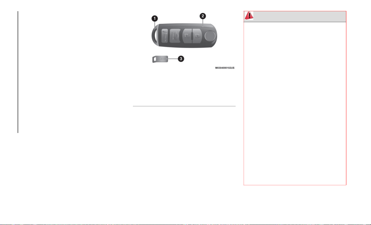
Key Fob
A code number is stamped on the plate and
attached to the key fob. Detach this plate
and store it in a safe place (not in the
vehicle) in case you need to replace the
emergency key.
Also, write down the code number and keep
it
in a separate safe and convenient place.
Do not keep it in the vehicle.
If the key fob is lost, contact an authorized
de
aler.
NOTE:
Key fob configuration may vary with
e
q
uipped features. Please see the example
shown below:
Key Fob
To use the emergency key, push the mechan-
ical latch on the back side of the key fob and
pu
ll out the emergency key.
NOTE:
Always keep a spare key fob if one is lost.
If a key fob is lost, see an authorized
dealer as soon as possible.
The driver must carry the key fob to ensure
the Keyless Entry System functions prop-
erly.
1 — Emergency Key
2 — Key Fob
3 — Key Code Number Plate
WARNING!
Before exiting a vehicle, always shift the
automatic transmission into PARK or the
manual transmission into FIRST gear or
REVERSE, apply the parking brake, then
turn the engine OFF, remove the key fob
from the vehicle and lock your vehicle.
Never leave children alone in a vehicle,
or with access to an unlocked vehicle.
Allowing children to be in a vehicle unat-
tended is dangerous for a number of
re
asons. A child or others could be seri-
ously or fatally injured. Children should
b
e
warned not to touch the parking
brake, brake pedal or the gear selector.
Do not leave the key fob in or near the
vehicle, or in a location accessible to
children. A child could operate power
windows, other controls, or move the
vehicle.
Do not leave children or animals inside
parked vehicles in hot weather. Interior
heat build-up may cause serious injury or
death.

13
Key Fob Functions
With A Vehicle Security Alarm System
The hazard warning lights will flash when the
ve
hicle security alarm system is armed or
disarmed.
With Advanced Keyless Function
A beep will sound when the doors, trunk lid,
an
d fuel filler door are locked or unlocked
using the key fob. The beep volume can be
adjusted or turned off.
Use the following procedure to change the
be
ep setting:
1. Place the ignition to the OFF position,
a
nd close the doors and the trunk lid.
2. Open the driver's door.
3
. Within 30 seconds of opening the driver's
d
oor, push and hold the lock button on
the key fob for five seconds.
NOTE:
The doors, trunk lid, and fuel filler door
will lock, and the beep will activate at the
current volume (if the beep is currently set
to not activate, it will not activate).
The setting changes when the lock button
on the key fob is pushed, and the beep will
activate at the set volume (if the beep
sound has been set to not activate, it will
not activate).
Complete changing the setting by doing any
of
the following:
Placing the ignition in the ACC or ON posi-
tion.
Closing the driver's door.
Opening the trunk lid.
Not operating the key fob for ten seconds.
Pushing any button, except the lock
button on the key fob.
Pushing a request switch on the exterior
door handle.
NOTE:
Refer to “Doors” in this chapter for further
i
n
formation.
The operation indicator light on the key fob
fl
ashes when the buttons are pushed.
Key Fob Buttons
Lock Button
To lock the doors, trunk lid, and fuel filler
do
or, push the lock button on the key fob.
The hazard warning lights will flash once and
a beep will sound.
Unlock Button
To unlock the doors and trunk lid, push the
un
lock button on the key fob, and the hazard
warning lights will flash twice.
The system can be set to unlock both doors.
Us
e the following procedure to change the
setting:
1. Place the ignition in the OFF position,
a
nd close the doors and trunk lid.
2. Open the driver's door.
3
. Within 30 seconds of opening the driver's
d
oor, push and hold the unlock button on
the key fob for five seconds.
NOTE:
The sound of the doors locking/unlocking
can be heard. After this, the system will
change the setting when the unlock button is
pushed (the sound of the doors locking/
unlocking can be heard).
GETTING TO KNOW YOUR VEHICLE
14
The setting change can be completed by
doing any one of the following:
Placing the ignition in the ACC or ON posi-
tion.
Closing the driver’s door.
Opening the trunk lid.
Not operating the key fob for ten seconds.
Pushing any button except the unlock
button on the key fob.
Pushing a request switch on the exterior
door handle.
Trunk Button
To open the trunk lid, push and hold the
t
r
unk button until the trunk lid opens.
Panic Button
To turn the Panic Alarm on or off, push and
h
o
ld the panic button on the key fob and
release. When the Panic Alarm is on, the
headlights will turn on, the park lights will
flash, the horn will pulse on and off, and the
turn signal lights will flash.
NOTE:
The panic button will work if the doors or
tr
unk are opened or closed.
Turning On The Alarm
Pushing the panic button for one second or
mo
re will trigger the alarm for about two
minutes and thirty seconds, and the
following will occur:
The horn sounds intermittently.
The hazard warning lights flash.
Turning Off The Alarm
The alarm will stop by pushing any button on
th
e key fob.
Operational Range
The system operates only when the driver is
in the vehicle or within operational range,
and the key fob is being carried.
Starting The Engine
Starting the engine may be possible even if
th
e key fob is outside the vehicle and close
to a door or window. Always start the engine
from the driver's seat.
If the vehicle is started, and the key fob is
no
t in the vehicle, the vehicle will not restart
after it is shut off. The ignition is placed in
the OFF position.
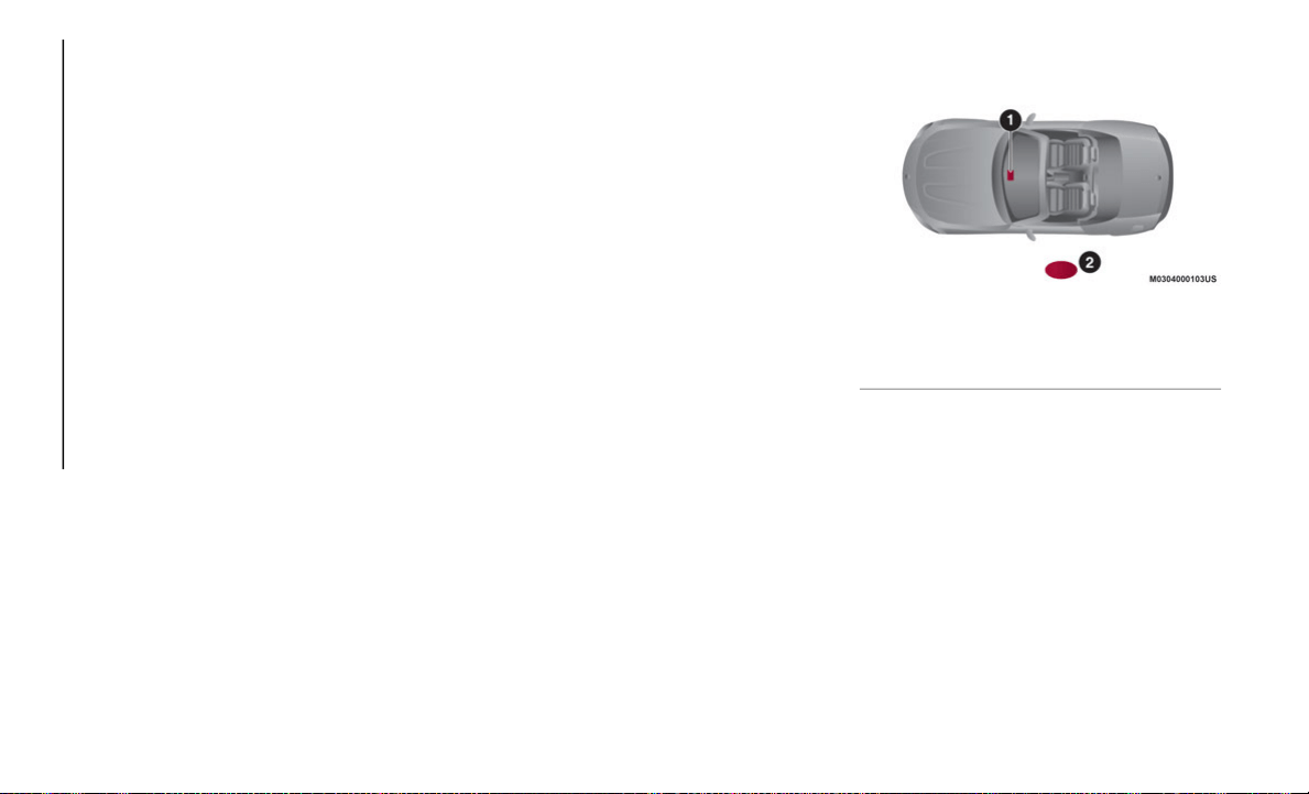
Key Fob Antenna Location
Key Fob Antenna Location
NOTE:
The engine may not start if the key fob is
pl
aced in or around the following areas:
Around The Instrument Panel
In The Storage Compartments
Key Fob Battery Replacement
If the key fob does not work, and the indi-
cator lights do not flash, the battery may be
lo
w or depleted.
1 — Interior Antenna
2 — Operational Range
15
Replace with a new battery (CR2025 type)
before the key fob becomes unusable.
The following conditions indicate that the
ba
ttery power is low:
Key indicator light (green) flashes in the
instrument cluster for about 30 seconds
af
ter the ignition is placed in the OFF posi-
tion.
The system does not operate, and the
operation indicator light on the key fob
does not flash when the buttons are
pushed.
The system's operational range is reduced.
NOTE:
Replacing the battery at an authorized dealer
is
recommended to prevent damage to the
key fob. If replacing the battery alone, follow
the instructions below.
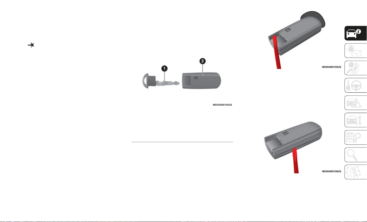
Replacing The Key Fob Battery
Proceed as follows:
1. P
ush the mechanical release button and
r
emove the emergency key.
Emergency Key Removed
2. Insert a coin, a flat blade screw driver, or
t
he tip of your emergency key into the
now exposed slot and carefully pry in the
direction of the arrows to open the cover
slightly.
Pry Case Left Side
3. I
nsert a coin, a flat blade screw driver, or
t
he tip of your emergency key into the
side gap and carefully pry in the direction
of the arrow to open the cover.
Pry Case Right Side
1 — Emergency Key
2 — Key Fob Case With Mechanical Re-
lease Button
GETTING TO KNOW YOUR VEHICLE
16
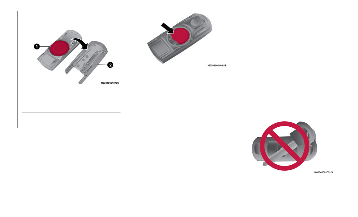
4. Separate the key fob case, then remove
the battery.
Remove Back Cover For Battery Replacement
5. Insert a new battery with the positive pole
f
acing up. Then, cover the battery with
the battery cap.
6. Close the cover and reinsert the emer-
g
ency key.
Install New Battery
NOTE:
Be careful not to allow the rubber ring to be
s
c
ratched or damaged. If the rubber ring
comes out, reinstall it before inserting a new
battery.
Key Suspend Function
If a key fob is left in the vehicle, key fob
functions are temporarily suspended to
prevent unlawful use of the vehicle.
To restore the functions, push the unlock
bu
tton on the functions-suspended key fob.
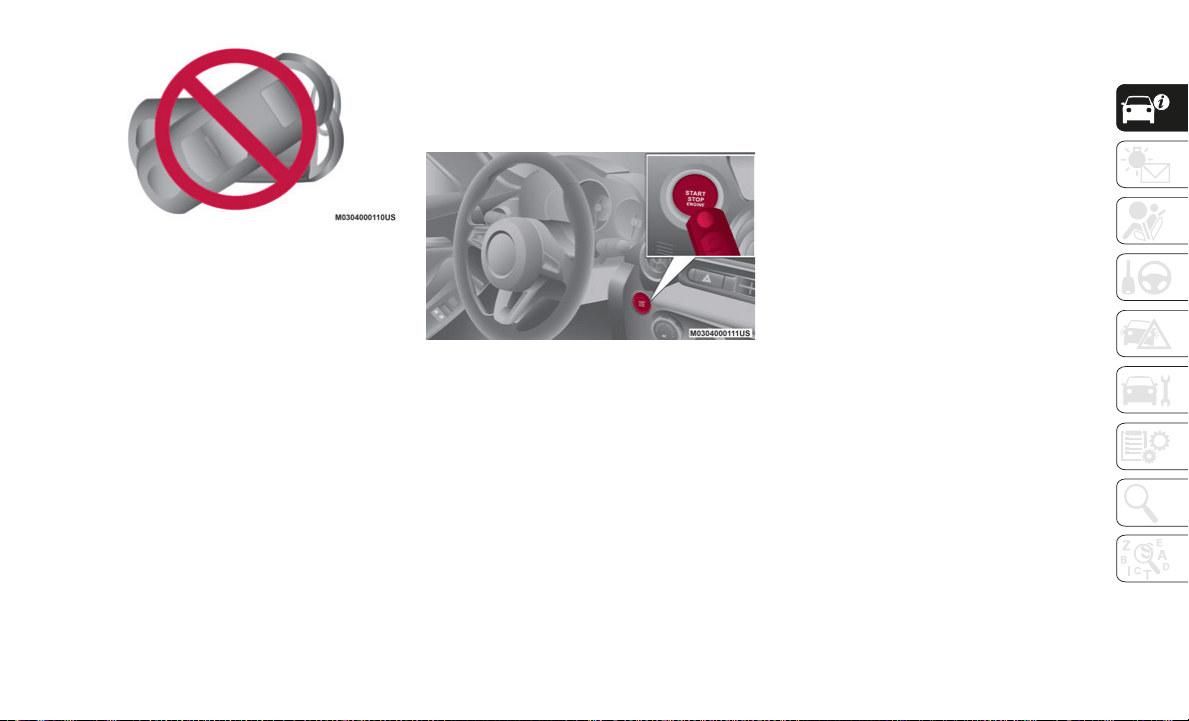
Engine Start Function When Key Fob
Battery Is Discharged
If a key fob has discharged or malfunctioned,
start the engine by holding the key fob over
the START/STOP ignition button. Be careful
to not allow the following because the signal
from the key fob will not be received
correctly, and the engine may not start:
Contact with metal parts of other key fobs
or metal objects
Contact from key fobs from other vehicle’s
equipped with an immobilizer system
Contact with devices for electronic
purchases or security passage touch
No Keys Touching The Key Fob
1 — Key Fob Battery
2 — Key Fob Case
17
No Key Fob Touching The Key Fob
If the engine cannot be started due to a
di
scharged key fob battery, the engine can
be started using the following procedure:
1. Continue to depress the brake pedal
f
irmly until the engine has completely
started.
2. Manual Transmission:
Continue to
depress the clutch pedal firmly until the
engine has completely started.
3. Verify that the keyless ignition start indi-
c
ator light (green) flashes.
4. T
ouch the START/STOP ignition button
u
sing the backside of the key fob while
the keyless ignition start indicator light
(green) flashes.
5. Verify that the keyless ignition start indi-
c
ator light (green) turns on.
6. P
ush the START/STOP ignition button to
s
tart the engine.
Discharged Key Fob Battery Start Procedure
When touching the START/STOP ignition
bu
tton using the backside of the key fob,
touch the START/STOP ignition button with
the key fob buttons facing up.
The engine cannot be started unless the
cl
utch pedal is fully depressed (manual
transmission) or the brake pedal is fully
depressed (automatic transmission).
If there is a malfunction with the START/
ST
OP ignition button function, the keyless
ignition start indicator light (amber) flashes.
In this case, the engine may start. However,
contact an authorized dealer as soon as
possible.
If the keyless ignition start indicator light
(g
reen) does not illuminate, perform the
operation from the beginning. If it does not
illuminate, contact an authorized dealer.
To change the ignition position without
st
arting the engine, perform the following
operations after the keyless ignition start
indicator light (green) turns on:
1. Release the clutch pedal (manual trans-
m
ission) or brake pedal (automatic trans-
mission).
2. P
ush the START/STOP ignition button to
c
hange the ignition position. The ignition
cycles in the order of ACC, ON, and OFF
each time the START/STOP ignition
button is pushed.
NOTE:
To change the ignition position again,
pe
rform the operation from the beginning.

GETTING TO KNOW YOUR VEHICLE
18
Emergency Operation For Starting The Engine
If the key warning light (red) illuminates, or
th
e keyless ignition start indicator light
(amber) flashes, this could indicate that the
engine may not start using the usual starting
method. Contact an authorized dealer as
soon as possible.
If this occurs, the engine can be
fo
rce-started. push and hold the START/
STOP ignition button until the engine starts.
Other procedures necessary for starting the
en
gine such as having the key fob in the
vehicle, and depressing the clutch pedal
(manual transmission) or the brake pedal
(automatic transmission) are required.
Key Fob Cautions
Because the key fob uses low-intensity radio
waves, it may not function under the
following conditions:
The key fob is carried with a communica-
tion device such as cellular phones
The key fob contacts or is covered by a
metal object
The key fob is near electronic devices such
as personal computers
Non-FCA genuine electronic equipment is
installed in the vehicle
There is equipment which discharges
radio waves near the vehicle
The key fob may consume battery power
excessively if it receives high-intensity
radio waves. Do not place the key fob near
electronic devices such as televisions or
personal computers
To avoid damage to the key fob, DO NOT:
Drop the key fob
Get the key fob wet
Disassemble the key fob unless replacing
the battery
Expose the key fob to high temperatures
such as direct sunlight
Expose the key fob to any kind of magnetic
field
Place heavy objects on the key fob
Put the key fob in an ultrasonic cleaner
Put any magnetized objects close to the
key fob
General Information
The following regulatory statement applies to
all Radio Frequency (RF) devices equipped
in this vehicle:
This device complies with Part 15 of the FCC
Ru
les and with Innovation, Science and
Economic Development Canada
license-exempt RSS standard(s). Operation
is subject to the following two conditions:
1. This device may not cause harmful inter-
f
erence, and
2. This device must accept any interference
r
eceived, including interference that may
cause undesired operation.
Le présent appareil est conforme aux CNR
d`
Innovation, Science and Economic Devel-
opment applicables aux appareils radio
e
x
empts de licence. L'exploitation est
autorisée aux deux conditions suivantes:
1. l'appareil ne doit pas produire de brouil-
l
age, et
2. l'utilisateur de l'appareil doit accepter
t
out brouillage radioélectrique subi,
même si le brouillage est susceptible
d'en compromettre le fonctionnement.
19
La operación de este equipo está sujeta a las
siguientes dos condiciones:
1. es posible que este equipo o dispositivo
n
o cause interferencia perjudicial y
2. este equipo o dispositivo debe aceptar
c
ualquier interferencia, incluyendo la
que pueda causar su operación no
deseada.
NOTE:
Changes or modifications not expressly
a
p
proved by the party responsible for compli-
ance could void the user’s authority to
o
p
erate the equipment.
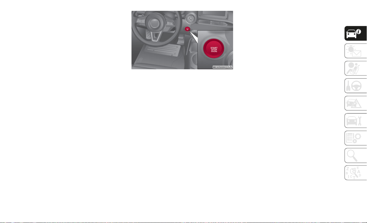
IGNITION SWITCH
Push Button Start Positions
The system operates only when the key fob is
within operational range.
When the clutch pedal (manual transmission)
or
brake pedal (automatic transmission) are
not depressed and the keyless ignition
START/STOP ignition button is pushed, the
ignition cycles in the order of OFF, ACC, and
ON. Pushing the START/STOP ignition button
again from ON/RUN position, places the igni
-
tion in the OFF position.
Keyless START/STOP Ignition Button
NOTE:
The engine starts by pushing the START/
STOP ignition button while depressing the
clutch pedal (manual transmission) or the
brake pedal (automatic transmission). To
change the ignition position, push the
START/STOP ignition button without
depressing the clutch or brake pedal.
Do not leave the ignition in the ON posi-
tion while the engine is not running. The
ba
ttery could discharge. If the ignition is
left in the ACC position (for automatic
transmission, the gear selector is in the
PARK position, and the ignition is in ACC),
the ignition cycles to the OFF position
automatically after about 25
minutes.
OFF
The power supply to electrical devices turns
of
f, and the keyless ignition start indicator
light (amber) also turns off. In the OFF posi
-
tion, the steering wheel is locked.
ACC (Accessory)
Some electrical accessories will operate and
th
e indicator light (amber) illuminates. In
the ACC position, the steering wheel is
unlocked.
The Keyless Entry System does not function
wh
ile the keyless ignition has been placed in
the ACC position, and the doors will not lock/
unlock even if they have been locked manu
-
ally.
ON
This is the normal running position after the
en
gine is started.
NOTE:
The indicator light (amber) turns off (the
i
n
dicator light [amber] illuminates when the
ignition has been placed in the ON position
and the engine is not running).
Some indicator lights/warning lights should
be
inspected before the engine is started.

GETTING TO KNOW YOUR VEHICLE
20
(Continued)
When the keyless ignition has been placed in
the ON position, the sound of the fuel pump
motor operating near the fuel tank can be
heard. This does not indicate a problem.
ADVANCED KEYLESS
ENTRY SYSTEM — IF
EQUIPPED
Advanced Keyless Entry System
The Advanced Keyless Entry System is an
enhancement that allows you to lock/unlock
the doors, trunk lid, and fuel filler door.
The Advanced Keyless Entry System allows
th
e driver to start the ignition with the push
of a button as long as the key fob is in the
passenger compartment.
If equipped, the vehicle security alarm
sy
stem may be armed/disarmed with the
push of the lock/unlock button located on
the key fob.
System Malfunctions/Warnings
System malfunctions or warnings are indi-
cated by the following warning lights or
be
eps (refer to “Getting To Know Your Instru-
ment Panel” for further information):
Key indicator light (red)
Ignition ON warning beep
WARNING!
Never use the PARK position as a substi-
tute for the parking brake. Always apply
th
e parking brake fully when exiting the
vehicle to guard against vehicle move
-
ment and possible injury or damage.
When exiting the vehicle, always make
sure the ignition is in the OFF mode,
remove the key fob from the vehicle, and
lock your vehicle.
Never leave children alone in a vehicle,
or with access to an unlocked vehicle.
Allowing children to be in a vehicle unat
-
tended is dangerous for a number of
re
asons. A child or others could be seri-
ously or fatally injured. Children should
b
e
warned not to touch the parking
brake, brake pedal or the transmission
gear selector.
Do not leave the key fob in or near the
vehicle, (or in a location accessible to
children), and do not leave the ignition
in the ACC or ON/RUN mode. A child
could operate power windows, other
controls, or move the vehicle.
Be sure the parking brake is fully disen-
gaged before driving; failure to do so can
le
ad to brake failure and a collision.
Always fully apply the parking brake
when leaving your vehicle, or it may roll
and cause damage or injury. Also be
certain to leave the transmission in
PARK. Failure to do so may allow the
vehicle to roll and cause damage or
injury.
Driving the vehicle with the parking
brake engaged, or repeated use of the
parking brake to slow the vehicle may
cause serious damage to the brake
system.
WARNING! (Continued)

21
Key fob removed from vehicle warning
beep
Request switch inoperable warning beep
Key fob left in trunk warning beep
Key fob left in vehicle warning beep
If you have a problem with the key fob, or the
ke
y fob is lost or stolen, contact an autho-
rized dealer as soon as possible for a replace-
ment and to make the lost or stolen key fob
i
n
operative.
NOTE:
Changes or modifications not approved by
t
h
e party responsible for compliance could
void the user's authority to operate the
equipment.
The Advanced Keyless Entry System oper-
ational range may vary due to local
we
ather conditions.
The Advanced Keyless Entry System is
fully operational (door/trunk lid/fuel filler
door lock/unlock) when the ignition is
placed in the OFF position. The Advanced
Keyless Entry System does not operate if
the ignition is placed in any position other
than the OFF position.
If the key fob does not operate when
pushing a button, the operational range
becomes too small, or the warning light
does not illuminate or flash, the battery
may be weak or discharged. To install a
new battery, refer to “Keys” in this chapter
for further information.
Battery life is about one year. Replace the
battery with a new one if the key indicator
light (green) flashes in the instrument
cluster. Replacing the battery about once
a year is recommended because the key
indicator light may not illuminate or flash
if the battery is low or depleted.
Additional key fobs may be obtained at an
authorized dealer. Up to six key fobs may
be used with the Advanced Keyless Entry
System per vehicle. Bring all key fobs to
an authorized dealer when additional keys
are required.
The Advanced Keyless Entry function allows
yo
u to lock/unlock the door, trunk lid, and
fuel filler door, or open the trunk lid while
carrying the key fob.
NOTE:
The Advanced Keyless Entry System func-
tions can be deactivated to prevent any
po
ssible adverse effect on a user wearing a
pacemaker or other medical device. If the
system is deactivated, you will be unable to
start the engine by carrying the key fob.
Contact an authorized dealer for details. If
the Advanced Keyless Entry System has
been deactivated, you can start the engine by
following the procedure indicated when the
key fob battery becomes discharged.
WARNING!
Radio waves from the key fob may affect
medical devices such as pacemakers:
before using the key fob near people who
use medical devices, ask the medical
device manufacturer or your physician if
radio waves from the key fob will affect the
device.
GETTING TO KNOW YOUR VEHICLE
22
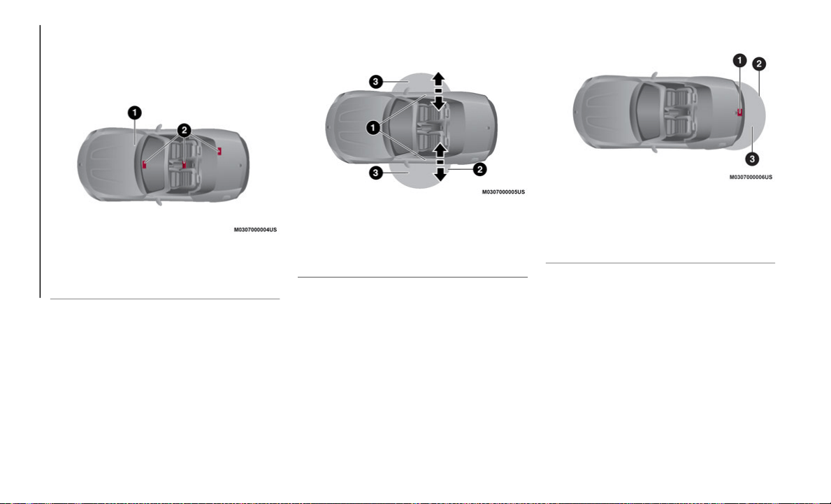
Operational Range
The system operates only when the driver is
in
or around the vehicle while the key fob is
being carried.
Advanced Keyless Entry Sensors
NOTE:
When the battery power is low, or in places
w
h
ere there are high-intensity radio waves or
noise, the operational range may reduce, or
the system may not operate.
Locking/Unlocking The Doors And The Trunk
Li
d
Request Switch Door Functions
NOTE:
The system may not operate if you are too
cl
ose to the windows or door handles.
Opening The Trunk Lid
Electronic Trunk Release
1 — Operational Range
2 — Interior Antennas
1 — Exterior Antenna
2 — Operational Range
3 — Distance (31 inches)
1 — Exterior Antenna
2 — Operational Range
3 — Distance (31 inches)

23
General Information
The following regulatory statement applies to
all Radio Frequency (RF) devices equipped
in this vehicle:
This device complies with Part 15 of the FCC
Ru
les and with Innovation, Science and
Economic Development Canada
license-exempt RSS standard(s). Operation
is subject to the following two conditions:
1. This device may not cause harmful inter-
f
erence, and
2. This device must accept any interference
r
eceived, including interference that may
cause undesired operation.
Le présent appareil est conforme aux CNR
d`
Innovation, Science and Economic Devel-
opment applicables aux appareils radio
e
x
empts de licence. L'exploitation est
autorisée aux deux conditions suivantes:
1. l'appareil ne doit pas produire de brouil-
l
age, et
2. l'utilisateur de l'appareil doit accepter
t
out brouillage radioélectrique subi,
même si le brouillage est susceptible
d'en compromettre le fonctionnement.
La operación de este equipo está sujeta a las
si
guientes dos condiciones:
1. es posible que este equipo o dispositivo
n
o cause interferencia perjudicial y
2. este equipo o dispositivo debe aceptar
c
ualquier interferencia, incluyendo la
que pueda causar su operación no
deseada.
NOTE:
Changes or modifications not expressly
a
p
proved by the party responsible for compli-
ance could void the user’s authority to
o
p
erate the equipment.
VEHICLE SECURITY ALARM
SYSTEM — IF EQUIPPED
Modifications And Add-On Equipment
FCA cannot guarantee the immobilizer and
security alarm system operation if the system
has been modified or if any add-on equip
-
ment has been installed.
NOTE:
To avoid damage to the vehicle, do not
mo
dify the system or install any add-on
equipment to the immobilizer, the security
alarm system, or the vehicle.
Immobilizer System
The immobilizer system allows the engine to
start only with a recognized key fob.
If someone attempts to start the engine with
an
unrecognized key fob, the engine will not
start, preventing unlawful vehicle use.
If you have a problem with the immobilizer
sy
stem or the key fob, contact an authorized
dealer.
To avoid damage to the key fob, DO NOT:
Drop the key fob
Get the key fob wet
Expose the key fob to any kind of magnetic
field
Expose the key fob to high temperatures
such as direct sunlight
NOTE:
Changes or modifications not expressly
approved by the party responsible for
compliance could void the user's authority
to operate the equipment.
If the engine does not start with the
correct key fob, and the warning light
keeps illuminating or flashing, the system

GETTING TO KNOW YOUR VEHICLE
24
may have a malfunction. Contact an
authorized dealer.
The key fobs carry a unique electronic
code. For this reason, and to assure your
safety, obtaining a replacement key fob
can only be done through an authorized
dealer, and will require some waiting time.
Always keep a spare key fob in case one is
lost. If a key fob is lost, contact an autho-
rized dealer as soon as possible.
If you lose a key fob, an authorized dealer
will reset the electronic codes of your
remaining key fobs and immobilizer
system. Bring all the remaining key fobs to
an authorized dealer to reset. Starting the
vehicle with a key fob that has not been
reset is not possible.
Operation
The engine may not start and warning
light may illuminate or flash if the key fob is
pl
aced in an area difficult for the system to
detect the signal, such as on the instrument
panel. Move the key fob to a location within
the signal range, place the ignition in the
OFF position, and restart the engine.
NOTE:
Signals from a TV, radio station, transceiver,
or
mobile telephone could interfere with your
immobilizer system. If you are using the
proper key fob and the engine fails to start,
check the
warning light.
Arming
The system is armed when the ignition is
cy
cled from the ON to OFF position. The
warning light in the instrument cluster
flashes every two seconds until the system is
disarmed.
Disarming
The system is disarmed when the ignition is
pl
aced in the ON position with the correct
programmed key fob. The
warning light
illuminates for about three seconds and then
tu
rns off. If the engine does not start with the
correct key fob, and the
warning light
remains illuminated or flashing, try the
fo
llowing:
Make sure the key fob is within the opera-
tional range for signal transmission.
Place the ignition in the OFF position, and
then restart the engine. If the engine does
not start after three or more tries, contact
an authorized dealer.
NOTE:
If the warning light flashes continu-
ously while you are driving, do not turn the
en
gine off. Contact an authorized dealer
and have it checked. If the engine is shut
off while the
warning light is flashing,
it will not be able to be restarted.
Because the electronic codes are reset
when the immobilizer system is repaired,
the keys are needed. Make sure to bring all
the key fobs to an authorized dealer so
that they can be programmed.
Vehicle Security Alarm System — If
Equipped
If the security alarm system detects an inap-
propriate entry into the vehicle, or the intru-
sion sensor detects movement in the vehicle,
w
h
ich could result in the vehicle or its
contents being stolen, the alarm alerts the
surrounding area by sounding the siren/horn
and flashing the hazard warning lights.
The system will not function unless it is
pr
operly armed. Follow the arming procedure
correctly.

25
Siren/Horn Triggering Conditions
The siren/horn sounds intermittently, and
th
e hazard warning lights flash for about
30 seconds when the system is triggered
by any one of the following:
Unlocking a door with an inside door lock
knob
Forcing open a door, the engine compart-
ment, or the trunk lid
Opening the hood by operating the hood
release handle
Placing the ignition in the ON position
without starting the engine
With the intrusion sensor: the intrusion
sensor detects a movement in the vehicle
The system will be triggered again (up to
10
times) if one of the above conditions
remains.
The trunk lid will not open when the vehicle
se
curity alarm system is activated.
If the battery becomes depleted while the
ve
hicle security alarm system is armed, the
siren will activate, and the hazard warning
lights will flash during the battery charging
or replacement process.
How To Arm The System
1. Close the windows and the convertible top.
2
. Place the ignition in the OFF position.
3
. Make sure the engine compartment,
c
onvertible top, doors, and trunk lid are
closed.
4. Push the lock button on the key fob, or
l
ock the driver's door from the outside
with the emergency key. The hazard
warning lights will flash once. With The
Advanced Keyless Entry function: push a
request switch. The
warning light in
the instrument cluster display flashes
t
w
ice per second for 20 seconds. After
20 seconds the system is fully armed.
The vehicle security alarm system can also
be
armed by activating the auto re-lock func-
tion with all the doors, the trunk lid and the
e
n
gine compartment closed.
The system will disarm if one of the following
op
erations takes place within 20 seconds
after pushing the lock button: To rearm the
system, perform the arming procedure again:
Unlocking any door
Opening any door
Opening the engine compartment
Placing the ignition in the ON position
When the doors are locked by pushing the
lo
ck button on the key fob, or using the emer-
gency key, the hazard warning lights will
f
l
ash once to indicate that the vehicle secu-
rity alarm system is armed.
NOTE:
If any door or trunk lid remains closed for
30 seconds, the doors, and trunk lid auto-
matically re-lock, and the vehicle security
a
l
arm system arms even if a window opens
or the convertible top is left down.
To reactivate the intrusion sensor, turn off
the armed vehicle security alarm system
and then rearm it.
The intrusion sensor is operational when
the vehicle security alarm system is
armed. To cancel the intrusion sensor,
push the intrusion sensor cancel button
each time the vehicle security alarm
system is armed.
GETTING TO KNOW YOUR VEHICLE
26
To Turn Off An Armed System
An armed system can be turned off using any
on
e of the following methods:
Pushing the unlock button on the key fob.
Starting the engine with the START/STOP
ignition button.
With The Advanced Keyless Entry function:
pushing a request switch on the exterior
door handles.
NOTE:
When the doors are unlocked by pushing the
u
n
lock button on the key fob, the hazard
warning lights will flash twice to indicate
that the system is turned off.
To Stop The Alarm
A triggered alarm can be turned off using any
on
e of the following methods:
Pushing the unlock button on the key fob.
Starting the engine with the START/STOP
ignition button.
With The Advanced Keyless Entry function:
pushing a request switch on the exterior
door handles or the electric trunk release
while the key fob is being carried.
The hazard warning lights will flash twice.
DOORS
Lock/Unlock With Emergency Key
The doors, trunk lid, and fuel door lock auto-
matically when the driver's door is locked
us
ing the emergency key.
Lock With Emergency Key: Insert key into
driver’s door and turn to the left (toward
front of car).
Unlock With Emergency Key: Insert key into
driver’s door and turn to the right (toward
back of car).
Both doors unlock when the driver's door is
un
locked using the emergency key.
Turn the emergency key toward the front to
lo
ck, toward the back to unlock.
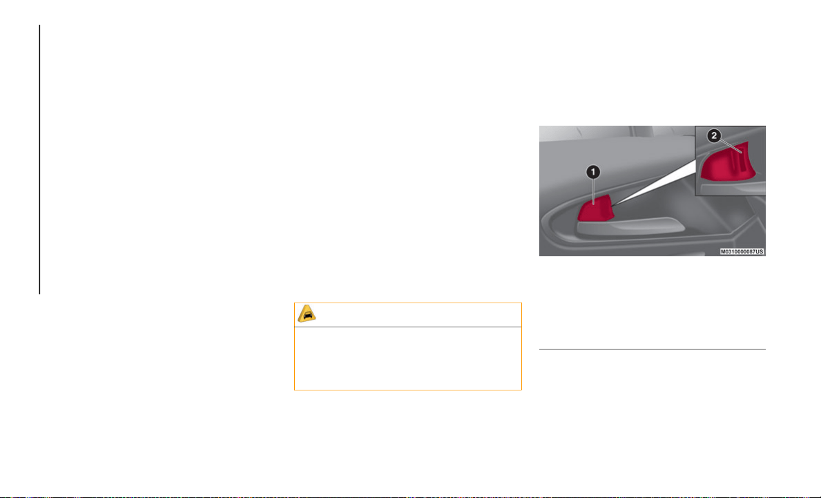
Manual Lock/Unlock Knob
Operation From Inside
To lock any door from the inside, push the
do
or lock knob. To unlock, pull it outward.
This does not operate the other door locks.
Interior Door Lock Knob
NOTE:
The red indication can be seen when the
do
or lock knob is unlocked.
CAUTION!
An unlocked vehicle is an invitation for
thieves. Always remove key fob from the
vehicle and lock all doors when leaving the
vehicle unattended.
1 — Door Lock Knob Position (Red Indica-
tor Not Seen When Locked)
2 — Door Unlock Knob Position (Red Indi-
cator Seen When Unlocked)
27
(Continued)
Operation From Outside
To lock the passenger door with the door lock
kn
ob from the outside, push the door lock
knob to the lock position and close the door
(holding the door handle in the open position
is not required).
NOTE:
When locking the door this way, be careful
n
o
t to leave the key fob inside the vehicle.
The driver's door lock knob cannot be used
while the driver's door is open.
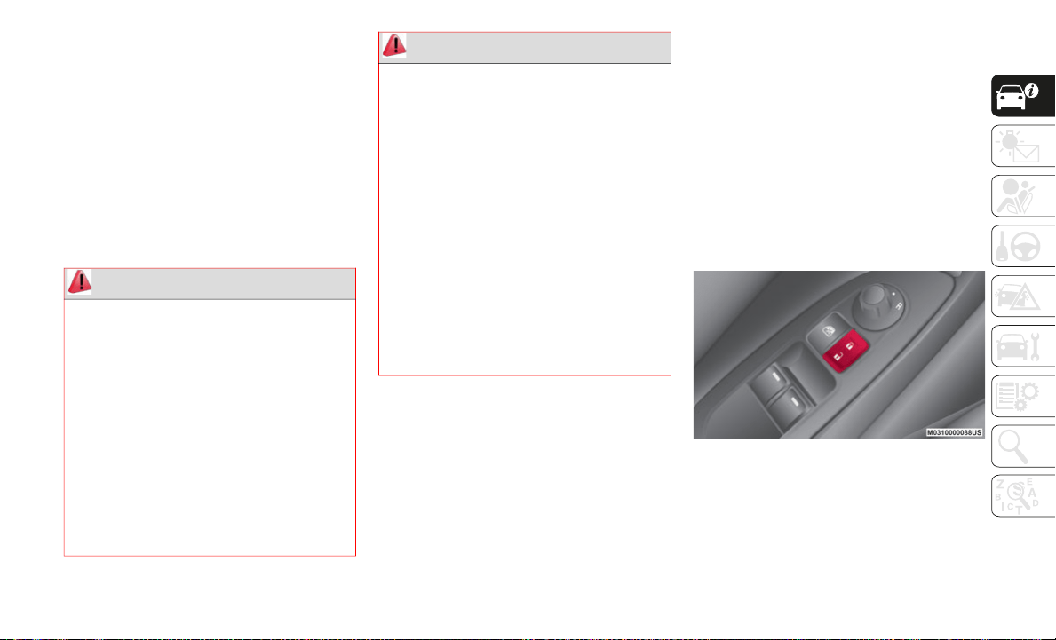
Central Lock/Unlock
The doors, trunk lid, and fuel door lock auto-
matically when the lock rocker switch is
pu
shed with both doors closed. Both unlock
when the unlock rocker switch is pushed.
NOTE:
The doors, trunk lid, and the fuel filler
door cannot be locked while any other door
is open.
The key fob may not be able to be detected
by the vehicle keyless-go system if it is
located next to a mobile phone, laptop or
other electronic device; these devices may
block the key fob’s wireless signal and
prevent the keyless-go system from
starting the vehicle.
Central/Power Door Lock Switch
WARNING!
For personal security and safety in the
event of a collision, lock the vehicle
doors before you drive as well as when
you park and leave the vehicle.
When leaving the vehicle, always remove
the key fob from the vehicle and lock
your vehicle. If equipped with Advanced
Keyless Entry, always make sure the
keyless ignition is in OFF position,
remove the key fob from the vehicle and
lock the vehicle. Unsupervised use of
vehicle equipment may cause severe
personal injuries or death.
Never leave children alone in a vehicle,
or with access to an unlocked vehicle.
Allowing children to be in a vehicle unat
-
tended is dangerous for a number of
re
asons. A child or others could be seri-
ously or fatally injured. Children should
b
e
warned not to touch the parking
brake, brake pedal or the gear selector.
Do not leave the key fob in or near the
vehicle, or in a location accessible to
children, and do not leave the ignition of
a vehicle equipped with Advanced
Keyless Entry in the ACC or ON/RUN
positions. A child could operate power
windows, other controls, or move the
vehicle.
WARNING! (Continued)
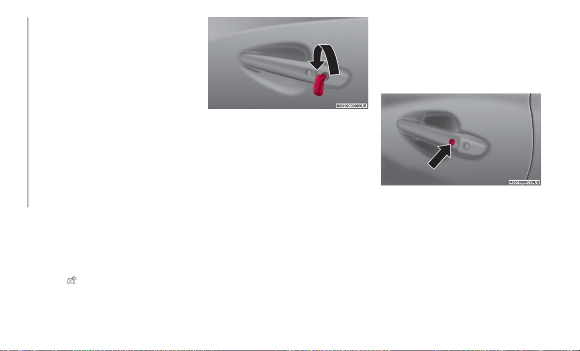
GETTING TO KNOW YOUR VEHICLE
28
Double Locking System — If Equipped
The double locking system is designed to
prevent someone who has broken into your
vehicle from opening the door from the
inside. If you have any problems with the
double locking system, contact an autho
-
rized dealer.
System Activation
Proceed as follows:
1. C
lose both the windows and the convert-
i
ble top.
2. Place the ignition in the OFF position,
a
nd take the key fob with you.
3. Close both doors and trunk lid.
4
. Insert the emergency key in the driver's
d
oor, turn the emergency key to the lock
position (counter clockwise/left), and
return it to the center position. Then turn
it to the lock position (counter clockwise/
left) again within three seconds.
5. The
indicator light illuminates for
about three seconds to indicate that the
sy
stem has been activated.
Emergency Key Lock Procedure
The system can be activated by pushing the
lo
ck button on the key fob twice within three
seconds.
With The Advanced Keyless Function:
the
system can be activated by pushing the
request switch on the exterior door handle
twice within three seconds.
NOTE:
The system cannot be activated when any
do
or is open.
System Deactivation
Unlock the driver's door, or place the ignition
i
n
the ON position. If the power supply is
interrupted (fuse blows or the battery is
disconnected), the system can only be deac
-
tivated by unlocking a door with the emer-
gency key.
Lock/Unlock With Advanced Keyless
Entry Function — If Equipped
The doors, trunk lid, and fuel filler door can
be locked/unlocked by pushing the request
switch on the exterior door handle while the
key fob is being carried.
Request Switch On Exterior Door Handle
To Lock
To lock the doors, trunk lid, and fuel filler
do
or, push the button on the exterior door
handle; the hazard warning lights will flash
once.
A beep will sound once.

29
To Unlock
Driver's door button is located on the exterior
do
or handle.
To unlock the doors, trunk lid, and fuel filler
do
or, push the button on the exterior door
handle; the hazard warning lights will flash
twice.
To unlock both doors and fuel filler door,
pu
sh the button on the exterior door handle
twice within three seconds. Two more beeps
will sound.
Front Passenger Door Request Switch:
To unlock both doors and fuel filler door,
pu
sh the button on the exterior door handle.
A beep will sound twice; the hazard warning
lights will flash twice.
NOTE:
Confirm that both doors, and fuel filler
door are securely locked.
For the trunk lid, move it without pushing
the electric trunk lid opener to verify that
the trunk lid has not been left open.
Both doors and the fuel filler door cannot
be locked when any door is open.
It may require a few seconds for the doors
to unlock after the request switch on the
exterior door handle is pushed.
The key fob may not be able to be detected
by the vehicle keyless-go system if it is
located next to a mobile phone, laptop or
other electronic device; these devices may
block the key fob’s wireless signal and
prevent the keyless-go system from
starting the vehicle.
A beep sound is heard for confirmation when
th
e doors, and fuel filler door are locked/
unlocked using the request switch on the
exterior door handle. If you prefer, the beep
sound can be turned off.
The volume of the beep sound can also be
ch
anged. Use the following procedure to
change the setting:
1. Place the ignition in the OFF position and
c
lose both of the doors and the trunk lid.
2. Open the driver's door.
3
. Within 30 seconds of opening the driver's
d
oor, push and hold the lock button on
the key fob for five seconds or longer. The
doors, and fuel filler door will lock, an
audible beep will activate at the currently
set volume (if the beep sound is currently
set to not activate, it will not activate).
The setting changes each time the lock
button on the key fob is pushed and the
beep will activate at the set volume (if
the beep sound has been set to not acti
-
vate, it will not activate).
4. The setting change is completed by doing
a
ny one of the following:
Place the ignition in the ACC or ON
position
Closing the driver's door
Opening the trunk lid
Not operating the key fob for 10 seconds
Pushing any button except the lock
button on the key fob
Pushing a request switch on the exte-
rior door handle
With Vehicle Security Alarm System
The hazard warning lights flash when the
s
e
curity alarm system is armed or disarmed.
Refer to “Vehicle Security Alarm System” in
this chapter for further information.
The setting can be changed so that the doors
an
d the fuel filler door are locked automati-

GETTING TO KNOW YOUR VEHICLE
30
cally without pushing the button on the exte-
rior door handle. Refer to “Personalization
Fe
atures” in “Getting To Know Your Instru-
ment Panel” for further information.
Auto-Lock Function
A beep is heard when both doors are closed
w
h
ile the key is carried. Both doors, the
trunk lid, and fuel door are locked automati
-
cally after about three seconds when the
Ad
vanced Keyless Entry key fob is out of the
operational range.
The hazard warning lights will flash once
(e
ven if the driver is in the operational range,
both doors, trunk lid, and fuel filler door are
locked automatically after about 30 seconds).
If outside of the operational range before the
do
ors and trunk lid are closed, or another key
fob is left in the vehicle, the auto-lock func
-
tion will not work.
Always make sure that both doors and trunk
l
i
d are closed and locked before leaving the
vehicle. The auto-lock function does not
close the power windows.
Auto Re-Lock Function
After unlocking with the button on the exte-
rior door handle, the doors and fuel filler door
wi
ll automatically lock if any of the following
operations are not performed within about
60 seconds.
If equipped with a vehicle security alarm
sy
stem, the hazard warning lights will flash
for confirmation.
The time required for the doors to lock auto-
matically can be changed. Refer to “Person-
alization Features” in “Getting To Know Your
In
strument Panel” for further information.
Locking/Unlocking With A Key Fob
The doors, trunk lid, and fuel filler door can
b
e
locked/unlocked by operating the keyless
entry system key fob. Refer to “Keys” in this
chapter for further information.
Locking/Unlocking With Door-Lock Switch
Both doors and the fuel filler door lock auto-
matically when the lock side is pushed. They
un
lock when the unlock side is pushed.
To lock the doors and fuel filler door from an
op
en door, push the lock side of the door lock
switch and then close the door.
NOTE:
When locking the doors this way, be careful
no
t to leave the key fob inside the vehicle.
Auto Lock/Unlock Function — If Equipped
When the vehicle speed exceeds 12 mph
(20 km/h), the doors, and fuel filler door lock
au
tomatically.
When the ignition is placed in the OFF posi-
tion, the doors and fuel filler door unlock
a
u
tomatically.
These functions can also be disabled so that
th
ey do not operate.
Auto Lock/Unlock Function Setting Change
Us
ing Door-Lock Switch
The doors and fuel filler door can be set to
lo
ck or unlock automatically by selecting any
one of the functions from the following table
and using the door-lock switch on the interior
door panel. There are only a total of six auto
lock/unlock settings available for automatic
transmission vehicles, and three for manual
transmission vehicles. Be sure to push the
unlock side of the driver's door-lock switch
the correct number of times according to the
selected function number. If the switch is
mistakenly pushed seven times on an auto
-
matic transmission vehicle or four times on a
ma
nual transmission, the procedure will be
cancelled. If this occurs, start the procedure
from the beginning.

31
(*) For other settings for the auto door lock function contact an authorized dealer.
NOTE:
Function number 3 is the factory setting for
yo
ur vehicle.
Settings Changing
Settings can be changed using the following
pr
ocedure:
1. Safely park the vehicle. Both doors must
r
emain closed.
2. Place the ignition in the ON position.
3
. Push and hold the lock side of the driver's
d
oor-lock switch within 20 seconds of
placing the ignition in the ON position,
and make sure a beep is heard about eight
seconds afterwards.
Function Number Function (*)
1 The auto door-lock function is disabled.
2 The doors and the fuel filler door lock automatically when the vehicle speed is about 12 mph
(2
0 km/h) or more.
3 The doors and the fuel filler door lock automatically when the vehicle speed is about 12 mph
(2
0 km/h) or more. The doors, trunk lid, and fuel filler door unlock when the ignition is cycled from
th
e ON to OFF position.
4 Automatic Transmission Vehicles Only:
when the ignition is placed in the ON position, and the gear
selector is shifted from PARK to any other gear position, the doors, and fuel filler door lock
automatically.
5 Automatic Transmission Vehicles Only:
when the ignition is placed in the ON position, and the gear
selector is shifted from PARK to any other gear position, the doors and the fuel filler door lock
automatically. When the dear selector is shifted to PARK while the ignition is placed in the ON
position, the doors and the fuel filler door unlock automatically.
6 Automatic Transmission Vehicles Only:
the doors and the fuel filler door lock automatically when the
vehicle speed is about 12 mph (20 km/h) or more. When the gear selector is shifted to PARK while
th
e ignition is placed in the ON position, the doors and the fuel filler door unlock automatically.
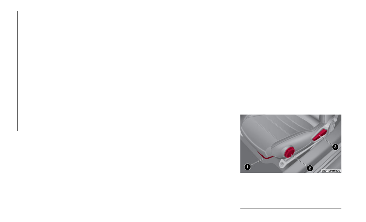
GETTING TO KNOW YOUR VEHICLE
32
4. Refer to the auto lock/unlock function
setting table. Determine the function
number for the desired setting. Push the
unlock side of the driver's door-lock
switch the same number of times as the
selected function number (example: if
function 2 is selected, push the unlock
side of the switch only two times).
5. Three seconds after the function setting
h
as been changed, a beep sound will
beep in the amount of the selected func
-
tion number (example: Function number
3
= three beep sounds).
Automatic Transmission Vehicles
The doors cannot be locked or unlocked while
th
e setting function is being performed.
The procedure can be cancelled by pushing
th
e lock side of the door-lock switch.
NOTE:
The vehicle lock-out prevention feature
prevents you from locking yourself out of the
vehicle. Both doors, trunk lid, and the fuel
filler door will automatically unlock if they
are locked using the power door locks with
any door open. If both the doors are closed
even though the trunk lid is open, both the
doors and the fuel filler door will lock.
Door Unlock (Control) System With Collision
Detection — If Equipped: this system auto-
matically unlocks the doors, trunk lid, and
t
h
e fuel filler door in the event the vehicle
is involved in an accident to allow passen
-
gers to get out of the vehicle immediately
an
d prevent being trapped inside. While
the ignition is being placed in the ON posi
-
tion and in the event the vehicle receives
an
impact strong enough to inflate the air
bags, both the doors, the trunk lid, and
fuel filler door are automatically unlocked
after about six seconds have elapsed from
the time of the accident. The doors, trunk
lid, and the fuel filler door may not unlock
depending on how an impact is applied,
the force of the impact, and other condi
-
tions of the accident. If door-related
s
y
stems or the battery is malfunctioning,
the doors, trunk lid, and the fuel filler door
will not unlock.
When opening a door, the power windows
open a little automatically. When closing
the door, the power windows close auto
-
matically. This is a function for improving
th
e sealing of the window, and it does not
mean there is a problem. If the vehicle
battery is disconnected for vehicle mainte
-
nance or other reasons, the power windows
wi
ll not open or close automatically. If the
power windows do not open or close, the
automatic open/close mechanism for the
windows must be reset.
SEATS
Manual Adjustment
Forward / Rearward
To move the seat forward or rearward, pull
th
e adjustment bar. Release the bar once the
desired position is reached. Using body pres
-
sure, move forward and rearward on the seat
to
be sure that the seat adjusters have
latched.
Manual Seat Adjustment
1 — Adjustment Bar
2 — Height Dial
3 — Recline Lever
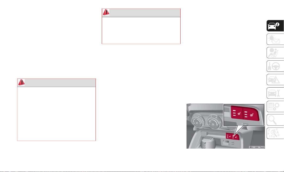
33
(Continued)
Height
To adjust the height for front edge of the seat
bo
ttom, rotate the dial to the desired posi-
tion.
Seat Recline
To recline the seatback, lift up the recline
l
e
ver and lean back until the desired position
has been reached, then release the lever.
Make sure the lever returns to its original
position and the seatback is locked in place
by attempting to push it forward and rear
-
ward.
Heated Seats
On some models, the front driver and
passenger seats may be equipped with
heaters in both the seat cushions and seat
-
backs. The controls for the front heated seats
ar
e located on the center instrument panel
below the climate controls.
The heated seats have three settings: High,
Me
dium, and Low. Push the switch once to
turn the heated seats on High, twice for
Medium, and three times for Low. Pushing
the switch a fourth time will turn the heated
seat off.
NOTE:
If the ignition is placed in the OFF position
while the seat warmer is operating (High,
Mid or Low), and then cycled ON again,
the seat warmer will automatically operate
at the temperature set before the engine
was turned off.
Use the seat warmer when the engine is
running. Leaving the seat warmer on for
long periods with the engine not running
could deplete the battery.
The temperature of the seat warmer
cannot be adjusted beyond High, Medium
and Low.
Once a heat setting is selected, heat will
be felt within two to five minutes.
Heated Seat Switches
WARNING!
Adjusting a seat while driving may be
dangerous. Moving a seat while driving
could result in loss of control which
could cause a collision and serious injury
or death.
Seats should be adjusted before
fastening the seat belts and while the
vehicle is parked. Serious injury or death
could result from a poorly adjusted seat
belt.
Do not ride with the seatback reclined so
that the shoulder belt is no longer resting
against your chest. In a collision you
could slide under the seat belt, which
could result in serious injury or death.
WARNING! (Continued)

GETTING TO KNOW YOUR VEHICLE
34
NON-ADJUSTABLE HEAD
RESTRAINTS
The non-adjustable head restraints are form
fitted into the upper structure of the seat-
back, and are designed to reduce the risk of
i
n
jury by restricting head movement in the
event of a rear impact. The seatback should
be properly adjusted to an upright position
where the head restraint is positioned as
close as possible to the back of the occu
-
pant’s head.
Driver And Passenger Head Restraints
This vehicle is equipped with non-adjustable
head restraints on the driver's and
passenger's seatbacks.
The non-adjustable head restraints consist of
a
trimmed foam covering over the upper
structure of the seatbacks and are intended
to help protect occupants from neck injury.
Adjust the seatbacks to their upright,
on
-road positions so that the head restraint is
positioned as close as possible to the back of
the occupant’s head.
WARNING!
Persons who are unable to feel pain to
the skin because of advanced age,
chronic illness, diabetes, spinal cord
injury, medication, alcohol use, exhaus
-
tion or other physical condition must
ex
ercise care when using the seat heater.
It may cause burns even at low tempera
-
tures, especially if used for long periods
of
time.
Do not place anything on the seat or
seatback that insulates against heat,
such as a blanket or cushion. This may
cause the seat heater to overheat. Sitting
in a seat that has been overheated could
cause serious burns due to the increased
surface temperature of the seat.
CAUTION!
Do not use organic solvents to clean the
seat. It may damage the seat surface and
the heater.
WARNING!
Be certain that the seatback is locked
securely into position. Otherwise, the seat
will not provide the proper stability for
passengers. An improperly latched
seatback could cause serious injury.
WARNING!
All occupants, including the driver,
should not operate a vehicle or sit in a
vehicle’s seat until the head restraints
are placed in their proper positions in
order to minimize the risk of neck injury
in the event of a crash.
Be certain that the seatback is securely
locked into position. If the seatback is
not securely locked into position the seat
will not provide the proper stability for
child seats and/or passengers. An
improperly latched seat could cause
serious injury.
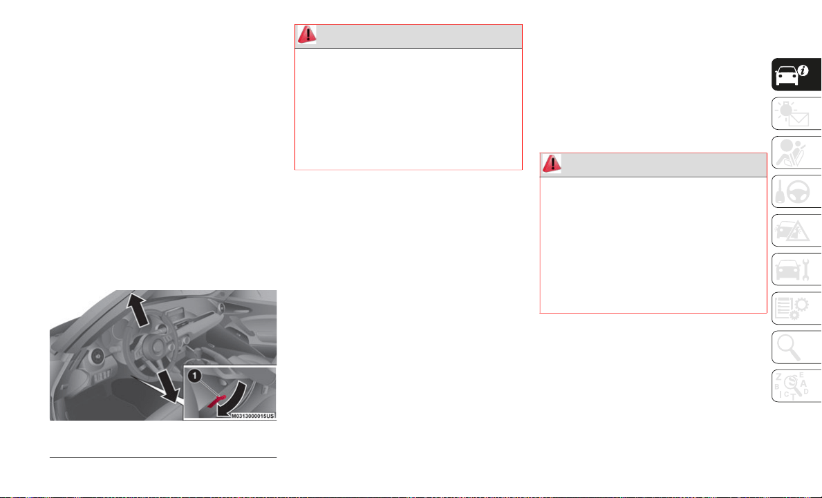
35
STEERING WHEEL
Steering Wheel Adjustment
To change the angle of the steering wheel:
1. With the gear selector in the PARK posi-
t
ion, pull the lock release lever (located
un
der the steering column) downward.
2. Tilt the steering wheel to the desired
p
osition.
3. Push the lock release lever upward to
l
ock the steering column.
4. Attempt to push the steering wheel
u
pward and downward to ensure it is
locked before driving.
Manual Tilt Adjustment
MIRRORS
Outside Mirrors
Be sure that all inside and outside mirrors
are adjusted to the desired position prior to
driving the vehicle.
Mirror Types:
Flat Type (Driver Side): flat surface mirror
Convex Type (Passenger Side): this mirror
has a slight curve
NOTE:
The passenger side convex outside mirror
wi
ll give a much wider view toward the rear
of the vehicle, and especially of the adjacent
lane.
The perceived distance of objects in the
ou
ter and inner regions of the wide angle
mirror is different.
1 — Lock Release Lever
WARNING!
Do not adjust the steering column while
driving. Adjusting the steering column
while driving or driving with the steering
column unlocked could cause the driver to
lose control of the vehicle. Be sure the
steering column is locked before driving
your vehicle. Failure to follow this warning
may result in serious injury or death.
WARNING!
Vehicles and other objects seen in the
passenger side convex mirror will look
smaller and farther away than they really
are. Relying too much on your passenger
side mirror could cause you to collide with
another vehicle or other object. Use your
inside mirror when judging the size or
distance of a vehicle seen in the passenger
side mirror.
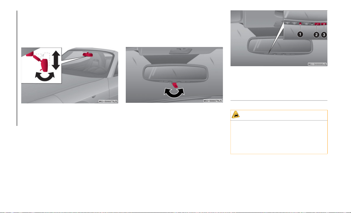
GETTING TO KNOW YOUR VEHICLE
36
Inside Day / Night Mirror
Rear View Mirror Adjustment
Before driving, adjust the rear view mirror to
ce
nter on the view through the rear window.
Manual Mirror Adjustment
NOTE:
Before adjusting the manual mirror, place
t
h
e mirror in the “day driving position” (lever
positioned forward, toward the windshield).
Reducing Glare From Headlights
1. P
ush the lever forward for day driving.
2
. Pull the lever rearward to reduce glare of
h
eadlights from vehicles at the rear.
Mirror Adjustment Lever
Automatic Dimming Mirror — If Equipped
The automatic dimming mirror automatically
reduces glare of headlights from vehicles at
the rear when the ignition is placed in the ON
position.
Automatic Dimming Mirror Buttons
1 — Light Sensor
2 — On
3 — Off
CAUTION!
To avoid damage to the mirror during
cleaning, never spray any cleaning solution
directly onto the mirror. Apply the solution
onto a clean cloth and wipe the mirror
clean.
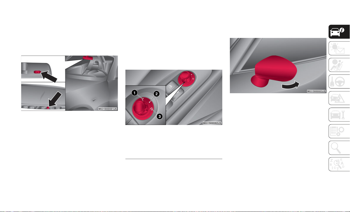
37
Push the off button (O) at the base of the
mirror to cancel the automatic dimming
function. The indicator light will turn off.
To reactivate the automatic dimming func-
tion, push the on button (I)
at the base of the
mirror. The indicator light will illuminate.
Light/Rain Sensor Locations
NOTE:
Do not use glass cleaner or suspend
objects on or around the light sensor.
Otherwise, light sensor sensitivity will be
affected and may not operate normally.
The automatic dimming function is
canceled when the ignition is placed in
the ON position and the gear selector is in
REVERSE.
Power Mirrors
The ignition must be in the ACC or ON posi-
tion to adjust the outside power mirrors.
Rotate the mirror switch to the left (L) or
ri
ght (R) to select which mirror to adjust.
Push the mirror control switch in the direc-
tion of the desired position.
Power Mirror Switch
After adjusting the mirror, lock the control by
ro
tating the switch to the center position to
prevent accidental movements.
Folding Mirrors
Manually fold the outside mirror rearward
until it is flush with the vehicle.
Outside Folding Mirror
If equipped with a driver side automatic
di
mming mirror, it is linked with the auto-
matic dimming rearview mirror inside the
v
e
hicle to automatically reduce headlight
glare from vehicles at the rear. Refer to
“Automatic Dimming Mirror” in this section
for further information.
NOTE:
The passenger door mirror does not have the
a
u
tomatic dimming feature.
1 — Left Position
2 — Center Position
3 — Right Position
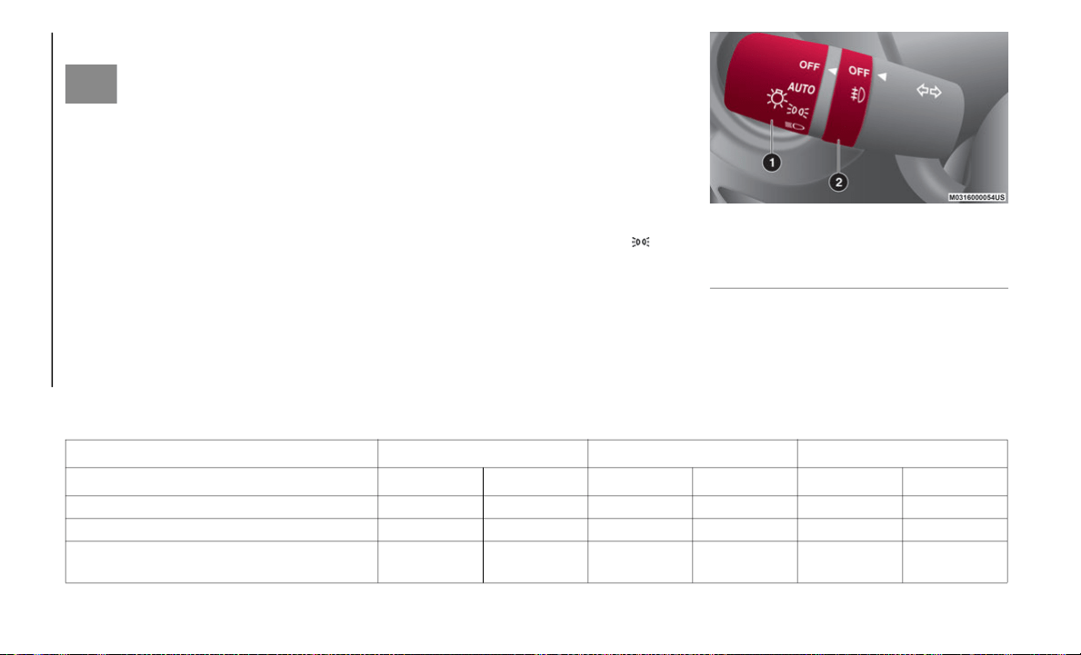
GETTING TO KNOW YOUR VEHICLE
38
Heated Mirrors — If Equipped
These mirrors are heated to melt
frost or ice. This feature will be
ac
tivated whenever you push the
Rear Window Defrost button. Refer to
“Climate Control System” in this chapter for
further information.
EXTERIOR LIGHTS
Headlights
The exterior light controls are located on the
multifunction lever on the left side of the
steering wheel. Rotate the headlight switch
to activate/deactivate the headlights, other
exterior lights and instrument panel illumi
-
nation.
When the lights are turned on, the indi-
cator in the instrument cluster will illumi-
nate.
Multifunction Lever
NOTE:
To prevent the battery from depleting, do not
l
e
ave the lights on while the engine is off.
Headlight Operation
(*) If the driver's door is opened, or 30 seconds have elapsed with the lights turned on, the lights turn off.
1 — Headlight Switch
2 — Fog Light Switch
Without Auto-Light Control
Switch Position OFF Daytime Running Lights High Beams
Ignition Position ON ACC Or OFF ON ACC Or OFF ON ACC Or OFF
Headlights Off Off Off Off On Off
Daytime Running Lights On Off Off Off Off Off
Tail Lights / Position Lights / License Plate
L
i
ghts / Instrument Panel Illumination
Off Off On On On On (*)

39
(*) The headlights and other light settings adjust automatically depending on the surrounding brightness detected by the sensor.
(**) While the lights are turned on, they will remain on even if the ignition is cycled to a position other than ON. If the driver’s door is opened, or
30 seconds have elapsed with the lights turned on, the lights turn off.
(***) When the ignition is placed in a position other than ON, the lights will not turn on even if the headlight switch is turned to AUTO.
(****) If the driver’s door is opened, or 30 seconds have elapsed with the lights turned on, the lights turn off.
Daytime Running Lights (DRLs)
The Daytime Running Lights (DRLs) turn on
automatically when the vehicle starts
moving.
They turn off when the parking brake is
en
gaged or the gear selector is shifted to the
PARK position (if equipped with automatic
transmission).
NOTE:
In some markets, the daytime running lights
ca
n be deactivated. Refer to “Settings” in
“Multimedia” in the User Guide for more
information.
High Beams
The headlights can be switched between
high and low beams by pushing the headlight
switch lever forward for high beams, and
pulling the lever rearward to return to low
beams.
When the headlight high beams are on, the
high beam indicator is illuminated in the
instrument cluster display.
Flash To Pass
You can signal another vehicle with your
headlights by partially pulling the headlight
lever toward the steering wheel. This will
cause the high beam headlights to turn on
until the lever is released.
With Auto-Light Control
Switch Position OFF AUTO
Daytime Running
Lig
hts
High Beams
Ignition Position ON
ACC Or
OFF
ON
ACC Or
OFF
ON
ACC Or
OFF
ON
ACC Or
OFF
Headlights Off Off Auto (*) Off Off Off On Off
Daytime Running Lights On Off Auto (*) Off Off Off Off Off
Tail Lights / Position Lights / License Plate
L
i
ghts / Instrument Panel Illumination
Off Off Auto
On (**)/
Off (***)
On On On On (****)
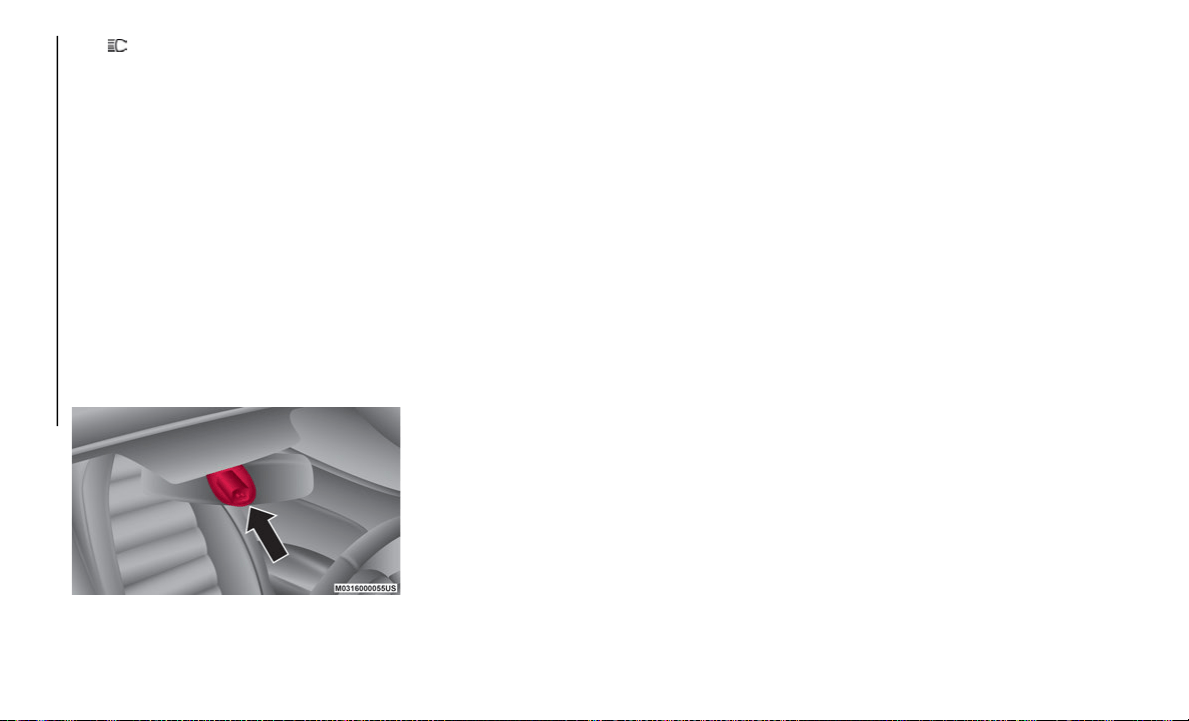
GETTING TO KNOW YOUR VEHICLE
40
The high beam indicator in the instru-
ment cluster display illuminates while the
hi
gh beams are active.
Automatic Lighting
When the headlight switch is in the AUTO
position and the ignition is placed in the ON
position, the light sensor will detect the
surrounding light levels and automatically
turns the headlights, other exterior lights and
dashboard illumination on or off.
NOTE:
Do not shade the light sensor by placing a
st
icker or a label on the windshield. Other-
wise, the light sensor will not operate
c
o
rrectly.
Light Sensor
The light sensor also works as a rain sensor
f
o
r the auto-wiper control. Keep hands and
scrapers clear of the windshield when the
wiper lever is in the AUTO position and the
ignition is placed in the ON position, as
fingers could be pinched or the wipers and
wiper blades damaged when the wipers acti
-
vate automatically. When cleaning the wind-
shield, be sure the wipers are turned off
co
mpletely when the engine is running.
NOTE:
The headlights, other exterior lights and
instrument panel lights may not turn off
immediately even if the surrounding area
becomes well-lit. This is because the light
sensor determines that it is night time if
the surrounding area is continuously dark
for several minutes such as inside long
tunnels, traffic jams inside tunnels, or in
indoor parking lots. In this case, the lights
turn off if the light switch is turned to the
OFF position.
When the headlight switch is in the AUTO
position and the ignition is placed in the
ACC or OFF position, the headlights, other
exterior lights, and dashboard illumination
will turn off.
The dashboard lights can be adjusted by
rotating the knob in the instrument cluster
display. The day/night mode can be
changed by rotating the knob until a beep
sound is heard.
The sensitivity of the automatic lights may
be changed by an authorized dealer.
Follow Me Home
The Follow Me Home Light System turns on
the headlights (low beams) for a period of
time after the ignition is placed in the OFF
position.
System Activation
With the ignition placed in the ACC or OFF
pos
ition, pull the headlight control lever rear-
ward and the low beam headlights will turn on.
The headlights turn off after a period of time
a
f
ter all doors are closed.
The time until the headlights turn off after all
of
the doors are closed can be changed
through the Connect system.
The headlights turn off if the lever is pulled
ag
ain while the headlights are on, or after
three minutes of no further action after the
first pull of the lever.
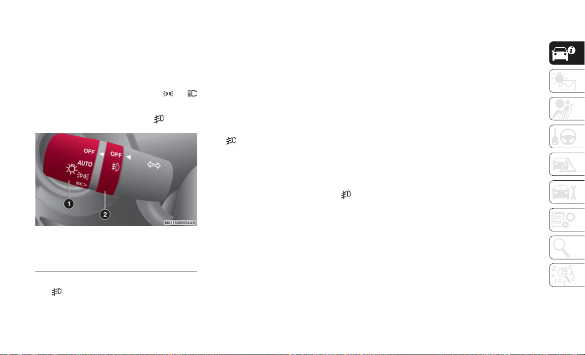
41
Front Fog Lights
The front fog light can be activated when the
ignition is in the ON position and the head-
lights or parking lights are on.
Activation
Turn the headlight switch to the or
position.
Rotate the fog light switch to the position.
Headlight Switch
The fog light indicator in the instrument
cluster illuminates while the front fog lights
a
r
e on.
Deactivation
Perform one of the following operations to
tu
rn off the front fog lights:
Rotate the fog light switch to the OFF posi-
tion.
Turn the headlight switch to the OFF posi-
tion.
Place the ignition in a position other than
ON.
The fog light indicator in the instrument
cluster goes off when the front fog light is
tu
rned off.
With Auto-Light Control
When the fog light switch is in the posi-
tion and the headlight switch is in AUTO
po
sition, the front fog lights will stay on.
Turn Signals
The ignition must be in the ON position to
use the turn signals and lane change assist.
Move the signal lever down (for a left turn) or
up
(for a right turn). The signal will
self-cancel after the turn is completed.
If the indicator light continues to flash after
a
turn, manually return the lever to its orig-
inal position.
The turn signal indicators in the instrument
c
l
uster display will flash according to the
operation of the turn signal lever to show
which signal is active.
NOTE:
If an indicator light stays on without flashing
or
if it flashes abnormally, one of the turn
signal bulbs may be burned out.
Lane Change Assist
Move the lever halfway toward the direction
of the lane change (until the indicator
flashes), and hold it there. It will return to
the off position when released.
Three-Flash Turn Signal
After releasing the turn signal lever, the turn
si
gnal indicator flashes three times.
The operation can be cancelled by moving
th
e lever in the direction opposite to which it
was operated.
The three-flash turn signal function can be
tu
rned on or off using the personalization
function in the radio.
1 — Headlight Switch
2 — Fog Light Switch

GETTING TO KNOW YOUR VEHICLE
42
Adaptive Front Lighting System (AFS) — If
Equipped
This system directs the main headlight
beams and adapts it to the driving conditions
around bends and turns, continuously and
automatically.
The system directs the headlight beam to
il
luminate the road in the best way, taking
into account the speed of the vehicle, the
bend or corner angle and the speed of
steering.
The Adaptive Front Lighting System is auto-
matically activated when the vehicle is
s
t
arted.
Leaving Home Light System
The Leaving Home Light System turns the
headlights on when the unlock button on the
key fob is pushed while away from the
vehicle.
Activation
With the ignition in the OFF position, and the
he
adlight switch is in the or position,
the headlights will illuminate when the
u
n
lock button on the key fob is pushed, and
the vehicle receives the signal.
The headlights turn off after 30 seconds.
The following lights turn on when the Leaving
Ho
me Light System is operated: low beams/
parking lights/tail lights/license plate lights.
Operation of the Leaving Home Light
System can be turned on or off through the
Connect system.
When the lock button on the key fob is
pushed, and the vehicle receives the
signal, the headlights turn off.
When the headlight switch is in a position
other than or , the headlights turn off.
Headlamp Leveling System — If Equipped
On some models, the angle of the headlights
will be automatically adjusted when turning
on the headlights.
Adjusting The Headlight When Abroad
Dipped headlights are adjusted for driving in
the country where the vehicle was originally
purchased.
When traveling in countries with opposite
dr
iving direction, to avoid flashing the drivers
on the other side of the road, you need to
cover areas of the headlight. For this opera
-
tion contact an authorized dealer.
WINDSHIELD WIPERS /
WASHER
Windshield Wipers And Washer
The windshield wiper/washer lever is located
on the right side of the steering wheel. The
ignition must be in the ON position before
using these features.
Windshield Wipers
Activate the windshield wipers by pushing
the wiper lever up or down.
With Intermittent Wiper
Set the lever to the intermittent position and
c
h
oose the interval timing by rotating the
center switch.
Switch positions:
or MIST: operation while pushing the
lever upward
OFF: stop
--- or INT: intermittent operation
— or LO: low speed operation
= or HI: high speed operation
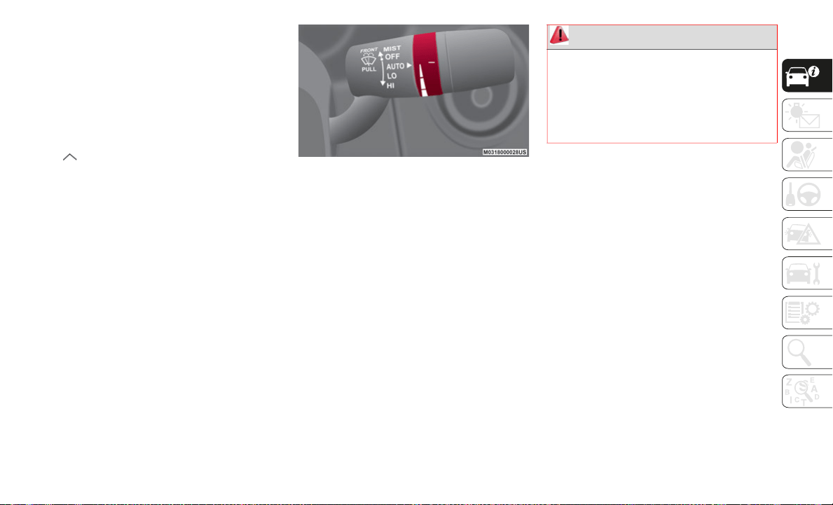
43
With Auto-Wiper Control
When the wiper lever is in the AUTO position,
th
e rain sensor will sense the amount of rain-
fall on the windshield and turns the wipers
o
n
or off automatically (off/intermittent/low
speed/high speed).
Switch positions:
or MIST: operation while pulling up
lever
OFF: stop
AUTO: auto control operation
— or LO: low speed operation
= or HI: high speed operation
Adjusting Rain Sensor Sensitivity
The sensitivity of the rain sensor can be
ad
justed by rotating the switch on the wiper
lever.
From the center position (normal), rotate the
sw
itch downward for higher sensitivity (+)
(faster response) or rotate it upward for less
sensitivity (-) (slower response).
Rain Sensor Adjustment
NOTE:
Do not shade the rain sensor by placing a
s
t
icker or a label on the windshield. Other-
wise the rain sensor will not operate
c
o
rrectly.
When the wiper lever is in the AUTO position
an
d the ignition is placed in the ON position,
the wipers may move automatically in the
following cases:
If the windshield above the rain sensor is
touched or wiped with a cloth
If the windshield is struck with a hand or
other object from either outside or inside
the vehicle
If the windshield is going to be cleaned, be
su
re the wipers are turned off. This is
important when clearing ice and snow.
Turning the auto-wiper lever from the OFF to
th
e AUTO position while driving activates the
windshield wipers once, after which they
operate according to the rainfall amount.
The auto-wiper control may not operate when
th
e rain sensor temperature is about 14°F
(–10°C) or lower, or about 185°F (85°C) or
higher.
If the windshield is coated with water repel-
lent, the rain sensor may not be able to sense
th
e amount of rainfall correctly and
auto-wiper control may not operate properly.
WARNING!
Keep hands and scrapers clear of the
windshield when the wiper lever is in the
AUTO position and the ignition is cycled
ON, as fingers could be pinched or the
wipers and wiper blades damaged when
the wipers activate automatically.
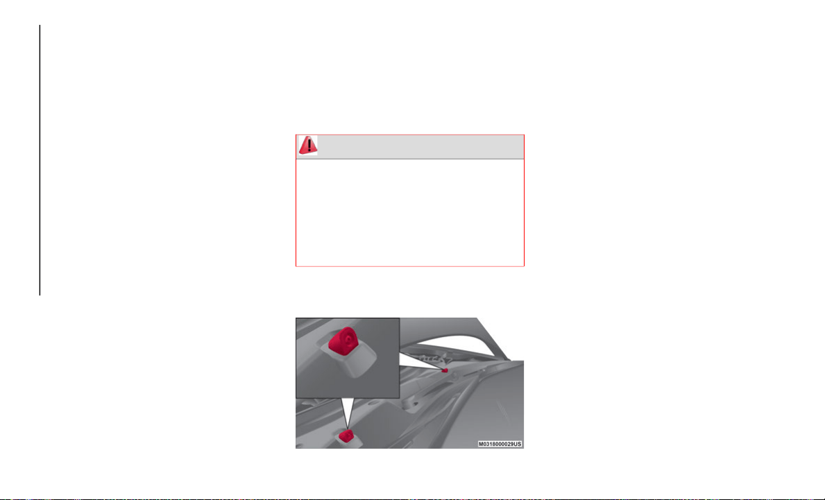
GETTING TO KNOW YOUR VEHICLE
44
If dirt or debris (such as ice or debris
containing salt water) adheres to the wind-
shield above the rain sensor or if the wind-
shield is iced, it could cause the wipers to
m
o
ve automatically.
However, if the wipers cannot remove this
ic
e, dirt or debris, the auto-wiper control will
stop operation. In this case, set the wiper
lever to the low speed position or high speed
position for manual operation, or remove the
ice, dirt or debris by hand to restore the
auto-wiper operation.
If the auto-wiper lever is left in the AUTO
po
sition, the wipers could operate automati-
cally from the effect of strong light sources,
e
l
ectromagnetic waves, or infrared light
because the rain sensor uses an optical
sensor.
It is recommended that the auto-wiper lever
be
turned to the OFF position other than
when driving the vehicle under rainy condi
-
tions.
The auto-wiper control functions can be
tu
rned off.
Windshield Washer
Pull the wiper/washer lever rearward and hold
it to spray washer fluid onto the windshield.
With the wiper lever in the OFF, intermittent,
or
AUTO position, the wipers will operate
continuously until the lever is released.
If the fluid level is normal and the washer
do
es not work, contact an authorized dealer.
Windshield Washer Nozzles
CLIMATE CONTROL
SYSTEM
Operating Tips
The air conditioning system will only operate
with the engine running.
To prevent the battery from being discharged
wh
ile the engine is off, do not leave the
Blower Control Knob on for extended periods
of time.
To improve system efficiency, clear all
ob
structions (leaves, snow and ice) from the
hood and the air inlet in the grille.
Use the air conditioning system to defog the
wi
ndows and dehumidify the air.
Recirculation mode should be used when
dr
iving through tunnels, while in a traffic
jam, or when you would like to quickly cool
the interior.
Use the outside air position for ventilation or
wi
ndshield defrosting.
If the vehicle has been parked in direct
su
nlight during hot weather, open the
windows to let warm air escape, and then run
the air conditioning system.
WARNING!
Sudden loss of visibility through the
windshield could lead to a collision. You
might not see other vehicles or other
obstacles. To avoid sudden icing of the
windshield during freezing weather, warm
the windshield with defroster before and
during windshield washer use.
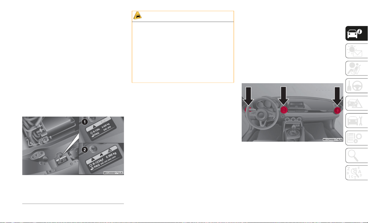
45
To keep the internal parts lubricated and the
system running smoothly, run the air condi-
tioner about ten minutes at least once a
m
o
nth.
Have the air conditioner checked before the
we
ather gets hot. A lack of refrigerant may
make the air conditioner less efficient. The
refrigerant specifications are indicated on a
label (1 or 2 depending on the market)
attached to the inside of the engine compart
-
ment. Check the label before refilling the
r
e
frigerant. If the wrong type of refrigerant is
used, it could result in a serious malfunction
of the air conditioner. For details, contact an
authorized dealer.
Label Location
Vent Operation
Adjusting The Vents
To adjust the direction of air flow, move the
ve
nt adjustment knob.
NOTE:
When using the air conditioner in humid
c
o
nditions, fog may blow from the vents.
This is a result of humid air being suddenly
cooled and does not indicate a system
malfunction.
Center Vents (Driver) and Side Vents
Center and side vents are located on the
da
shboard.
Air vent open/close: the air vents can be
fully opened and closed by rotating the air
vent knob.
Air flow direction adjustment: use the air
vent knob to adjust the center vents to the
desired position.
Side Air Vents
1 — Option 1
2 — Option 2
CAUTION!
The system uses a coolant that is
compatible with the laws in force in the
countries where the vehicle is sold, R134a
or R1234yf (indicated on a specific plate
in the engine compartment). The use of
other coolants affects the efficiency and
condition of the system. Also the
compressor coolants used must be
compatible with the indicated coolant.
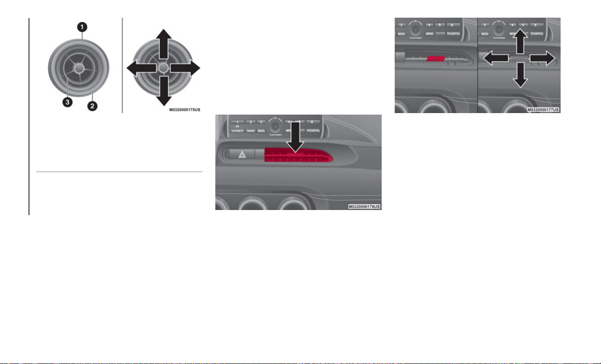
GETTING TO KNOW YOUR VEHICLE
46
Operating the Side Air Vents
Center Vents (Front Passenger)
Center vents are located on the dashboard.
Air vent open/close: use the Center Vent
tab to open/close the center vents.
Air flow direction adjustment: use the
Center Vent tab to adjust the center vents
to the desired position.
Central Air Vent
Central Air Vent Tab And Vent Directions
1 — Open Position
2 — Closed Position
3 — Air Vent Knob
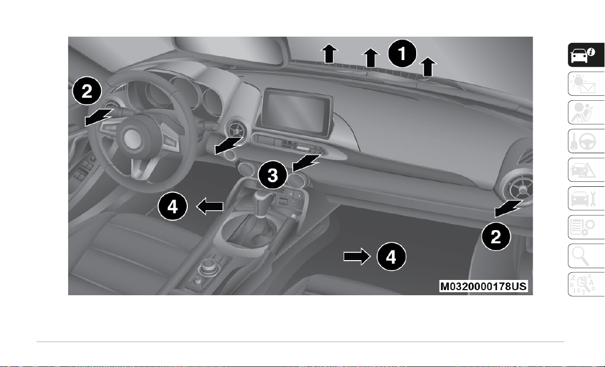
47
Airflow Mode
Airflow Locations
1 — Fixed Upper Air Diffuser 3 — Adjustable Center Air Vent
2 — Adjustable Side Air Vents 4 — Floor Vents
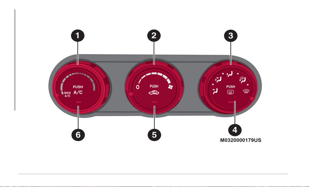
GETTING TO KNOW YOUR VEHICLE
48
Manual Climate Control System
With MAX A/C Function
Manual Climate Controls With MAX A/C
1 — Temperature Control Knob 4 — Rear Window Defrost Button
2 — Blower Control Knob 5 — Air Recirculation Button
3 — Mode Selector Knob 6 — A/C Button
49
Controls
1 – Temperature Control Knob
This dial controls the interior temperature of
th
e vehicle.
Turn it clockwise for hotter temperatures and
co
unterclockwise for colder temperatures.
MAX A/C (If Equipped):
When the Mode
Selector Knob is set to or , the Blower
Control Knob is in a position other than 0, and
t
h
e temperature control knob is in the
maximum cold position, the Recirculation
Button will activate and the A/C (Air Condi
-
tioner) will turn on automatically. If A/C is not
de
sired, press the A/C Button to turn it off.
2 – Blower Control Knob
The blower has seven speeds. Turn the knob
c
l
ockwise to increase blower speed or coun-
terclockwise to decrease blower speed.
3 – Mode Selector Knob
Turn the Mode Selector Knob to select the
a
i
r flow mode.
The mode selector dial can be set at the
in
termediate positions (?) between each
mode.
Set the knob to an intermediate position if
yo
u want to split the air flow between the two
modes.
For example, when the Mode Selector Knob
is
at the intermediate position (?) between
the
and positions, air flow from the
floor vents is less than that of the posi-
tion.
4 – Rear Window Defrost Button
The Rear Window Defrost Button clears fog
a
n
d frost from the rear window. The ignition
must be on to use the defroster.
Push the button to turn on the Rear Window
De
froster. The Rear Window Defroster oper-
ates for about 15 minutes and then turns off
a
u
tomatically. The button LED will illumi-
nate when the defroster is operating.
To turn off the Rear Window Defroster before
t
h
e end of 15 minutes, push the button
ag
ain.
NOTE:
Before opening the convertible top, make
sure the Rear Window Defrost Button is
turned off. Otherwise, the heat generated
from the defroster could damage the
convertible top and the internal material.
This defroster is not designed for melting
snow. If there is an accumulation of snow
on the rear window, remove it before using
the defroster.
CAUTION!
Failure to follow these cautions can cause
damage to the heating elements:
Use care when washing the inside of the
rear window. Do not use abrasive window
cleaners on the interior surface of the
window. Use a soft cloth and a mild
washing solution, wiping parallel to the
heating elements. Labels can be peeled
off after soaking with warm water.
Do not use scrapers, sharp instruments,
or abrasive window cleaners on the inte-
rior surface of the window.
Keep all objects a safe distance from the
window.

GETTING TO KNOW YOUR VEHICLE
50
Mirror Defroster (If Equipped): To turn on the
mirror defroster, place the ignition in the ON
position and push the Rear Window Defroster
Button.
5 – Air Recirculation Button
Push the Air Recirculation Button to select
be
tween outside air and recirculated air posi-
tions.
Recirculated Air Position:
(LED on) Outside
air is shut off when this position has been
activated. Use this position when going
through tunnels, driving in congested traffic
(high engine exhaust areas), or when quick
cooling of the vehicle is desired.
Outside Air Position:
(LED off) Outside air is
allowed to enter the cabin. Use this mode for
ventilation or windshield defrosting.
NOTE:
Do not use the Outside Air Position in cold or
ra
iny weather; this is dangerous as it will
cause the windows to fog up. Your vision will
be hampered, which could lead to a serious
accident.
6 – A/C Button
Push the A/C Button to turn on the air condi-
tioner.
The LED on the switch will illuminate when
th
e Blower Control Knob is in any position
except the OFF position.
Push the button again to turn off the air
co
nditioner.
NOTE:
The air conditioner may not function when
t
h
e outside temperature approaches 32°F
(0°C).
Heating
Proceed as follows:
1. Set the Mode Selector Knob to the
position.
2. Set the Air Recirculation Button to the
o
utside air position.
3. Set the Temperature Control Dial to the
h
ot position.
4. Set the Blower Control Knob to the
d
esired speed.
5. If dehumidified heating is desired, turn
o
n the air conditioner.
If the windshield fogs up easily, set the Mode
Se
lector Knob to the position.
If cooler air is desired at face level, set the
Mo
de Selector Knob to the position and
adjust the Temperature Control Knob to
m
a
intain comfort.
The floor vents will blow warmer air while the
si
de air vents will blow cooler air (except
when the temperature control dial is set at
the maximum hot or cold position).
Cooling (With Air Conditioner)
Proceed as follows:
1. Set the Mode Selector Knob to the
position.
2. Set the Temperature Control Knob to the
c
old position.
3. Set the Blower Control Knob to the
d
esired speed.
4. Turn on the air conditioner by pushing
t
he A/C Button.
5. After cooling begins, adjust the Blower
C
ontrol Knob and Temperature Control
Knob as needed to maintain comfort.

51
NOTE:
If the air conditioner is used while driving
up large hills or in heavy traffic, monitor
the Engine Coolant Temperature Warning
Light to see if it is illuminated or flashing.
The air conditioner may cause engine
overheating in these situations. If the
warning light is illuminated or flashing,
turn the air conditioning off immediately.
When maximum cooling is desired, set the
Temperature Control Knob to the extreme
cold position, push the Air Recirculation
Button to activate the recirculated air
position, and then turn the fan control dial
fully clockwise.
If warmer air is desired at floor level, set
the Mode Selector Knob to the posi-
tion, and adjust the Temperature Control
Kn
ob to maintain comfort.
The floor vents will blow warmer air while
the side air vents will blow cooler air
(except when the temperature control dial
is set at the maximum hot or cold posi
-
tion).
Ventilation
Proceed as follows:
1. Set the Mode Selector Knob to the
position.
2. Set the Air Recirculation Button to the
o
utside air position.
3. Set the Temperature Control Knob to the
d
esired position.
4. Set the Blower Control Knob to the
d
esired speed.
Windshield Defrosting And Defogging
Proceed as follows:
1. Set the Mode Selector Knob to the Front
De
frost position.
2. Set the Temperature Control Knob to the
de
sired position.
3. Set the Blower Control Knob to the desired
sp
eed.
4. If dehumidified heating is desired, turn on
th
e air conditioner.
NOTE:
For maximum defrosting, turn on the air
conditioner, set the Temperature Control
Knob to the extreme hot position, and turn
the Blower Control Knob fully clockwise.
If warm air is desired from the floor vents,
set the Mode Selector Knob to the posi-
tion.
If equipped with MAX A/C, the Recircula-
tion Button can be set to the Recirculated
Ai
r position, when the Blower Control
Knob is on, and the Mode Selector Knob is
set to the Front Defrost position.
WARNING!
Set the temperature control to the hot or
warm position when defogging (Front
Defrost position). Using the Front Defrost
position with the temperature control set
to the cold position is dangerous as it will
cause the outside of the windshield to fog
up. Your vision will be hampered, which
could lead to a serious accident.

GETTING TO KNOW YOUR VEHICLE
52
Dehumidifying (With Air Conditioner)
Operate the air conditioner in cool or cold
weather to help defog the windshield and
side windows.
Proceed as follows:
1. Set the Mode Selector Knob to the
d
esired position.
2. Set the Air Recirculation Knob to the
o
utside air position.
3. Set the Temperature Control Knob to the
d
esired position.
4. Set the Blower Control Knob to the
d
esired speed.
5. Turn on the air conditioner by pressing
t
he A/C Button.
NOTE:
One of the functions of the air conditioner is
de
humidifying the air. To use this function,
the temperature does not have to be set to
cold. Set the Temperature Control Knob to
the desired position (hot or cold), and turn on
the air conditioner to dehumidify the cabin
air.
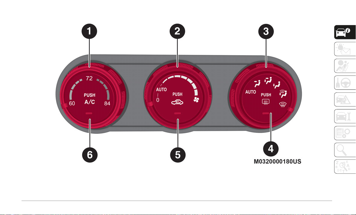
53
Automatic Climate Control System
Automatic Climate Controls — Type A
1 — Temperature Control Knob 4 — Rear Window Defrost Button
2 — Blower Control Knob 5 — Air Recirculation Button
3 — Mode Selector Knob 6 — A/C Button
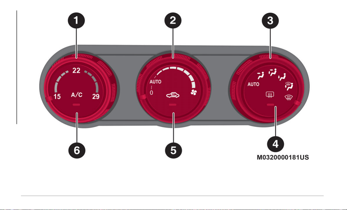
GETTING TO KNOW YOUR VEHICLE
54
Automatic Climate Controls — Type B
1 — Temperature Control Knob 4 — Rear Window Defrost Button
2 — Blower Control Knob 5 — Air Recirculation Button
3 — Mode Selector Knob 6 — A/C Button

55
Controls
1 – Temperature Control Knob
This knob controls internal temperature of
th
e vehicle. Turn it clockwise for hotter
temperatures and counterclockwise for
colder temperatures.
2 – Blower Control Knob
The fan has seven speeds. Turn the clock-
wise to increase blower speed or counter-
clockwise to decrease blower speed/enter
A
u
to mode.
AUTO Position:
The blower speed is automat-
ically controlled by the system based upon
th
e set temperature.
0 Position: To turn off the system, set the dial
t
o the 0 position.
3 – Mode Selector Knob
Turn the Mode Selector Knob to select the
a
i
r flow mode.
AUTO Position:
The air flow automatically
adjusts based upon the selected tempera-
ture.
NOTE:
With the air flow mode set to the posi-
tion, and the Temperature Control Knob is
se
t to a medium temperature, the floor
vents will blow warmer air, and the center
and side air vents will blow cooler air.
When the Blower Control Knob is on, and
the Mode Selector Knob is in the posi-
tion, the air conditioner is automatically
t
u
rned on, and the Air Recirculation
Button is automatically set to the outside
air position for windshield defrosting.
4 – Rear Window Defrost Button
The Rear Window Defroster clears fog and
fr
ost from the rear window. The ignition must
be placed in the ON position to use the
defroster.
Push the button to turn on the Rear Window
De
froster.
The Rear Window Defroster operates for
ab
out 15 minutes, and then turns off auto-
matically.
The button LED will illuminate when the
d
e
froster is operating.
To turn off the Rear Window Defroster before
th
e end of 15 minutes, push the switch
ag
ain.
CAUTION!
Failure to follow these cautions can cause
damage to the heating elements:
Before opening the convertible top,
make sure the Rear Window Defrost
button is turned off. Otherwise, the heat
generated from the defroster could
damage the convertible top and the
internal material.
Use care when washing the inside of the
rear window. Do not use abrasive window
cleaners on the interior surface of the
window. Use a soft cloth and a mild
washing solution, wiping parallel to the
heating elements. Labels can be peeled
off after soaking with warm water.
Do not use scrapers, sharp instruments,
or abrasive window cleaners on the inte-
rior surface of the window.
Keep all objects a safe distance from the
window.

GETTING TO KNOW YOUR VEHICLE
56
NOTE:
This defroster is not designed for melting
sn
ow. If there is an accumulation of snow on
the rear window, remove it before using the
defroster.
Mirror Defroster (If Equipped):
To turn on the
mirror defroster, switch the ignition on and
push the Rear Window Defroster Button.
5 – Air Recirculation Button
Press the Air Recirculation Button to select
be
tween outside air and recirculated air posi-
tions.
Recirculated Air Position:
(LED On) Outside
air is shut off when this position has been
activated. Use this position when going
through tunnels, driving in congested traffic
(high engine exhaust areas), or when quick
cooling of the vehicle is desired.
Outside Air Position:
(LED Off) Outside air is
allowed to enter the cabin. Use this mode for
ventilation or windshield defrosting.
NOTE:
Do not use the Recirculated Air Position in
co
ld or rainy weather. Using the Recirculated
Air Position in cold or rainy weather is
dangerous as it will cause the windows to fog
up. Your vision will be hampered, which
could lead to a serious accident.
6 – A/C Button
Push the A/C Button to turn on the air condi-
tioner.
The LED on the switch will illuminate when
t
h
e Blower Control Knob is in any position
except the off position.
Push the button again to turn off the air
co
nditioner.
NOTE:
The air conditioner may not function when
t
h
e outside temperature approaches 32°F
(0°C).
Operation Of Automatic Air Conditioning
Proceed as follows:
1. Set the mode selector knob to the AUTO
p
osition.
2. Set the Air Recirculation Button to the
o
utside air position (indicator light
turned off).
NOTE:
If the recirculated air position is used for
l
o
ng periods in cold weather or high
humidity, the windshield may fog up more
easily.
3. Set the Blower Control Knob to the AUTO
p
osition.
4. Push the A/C button to operate the air
c
onditioning (indicator light on).
5. Set the Temperature Control Knob to the
d
esired position.
6. To turn off the system, set the blower
c
ontrol knob to the 0 position.
Setting the temperature to maximum hot or
co
ld will not provide the desired temperature
at a faster rate.
When selecting heat, the system will restrict
ai
r flow until it has warmed to prevent cold
air from blowing out of the vents.
For an optimal cabin temperature, set the
te
mperature close to 77°F (25°C). Adjust to
the desired temperature if necessary.
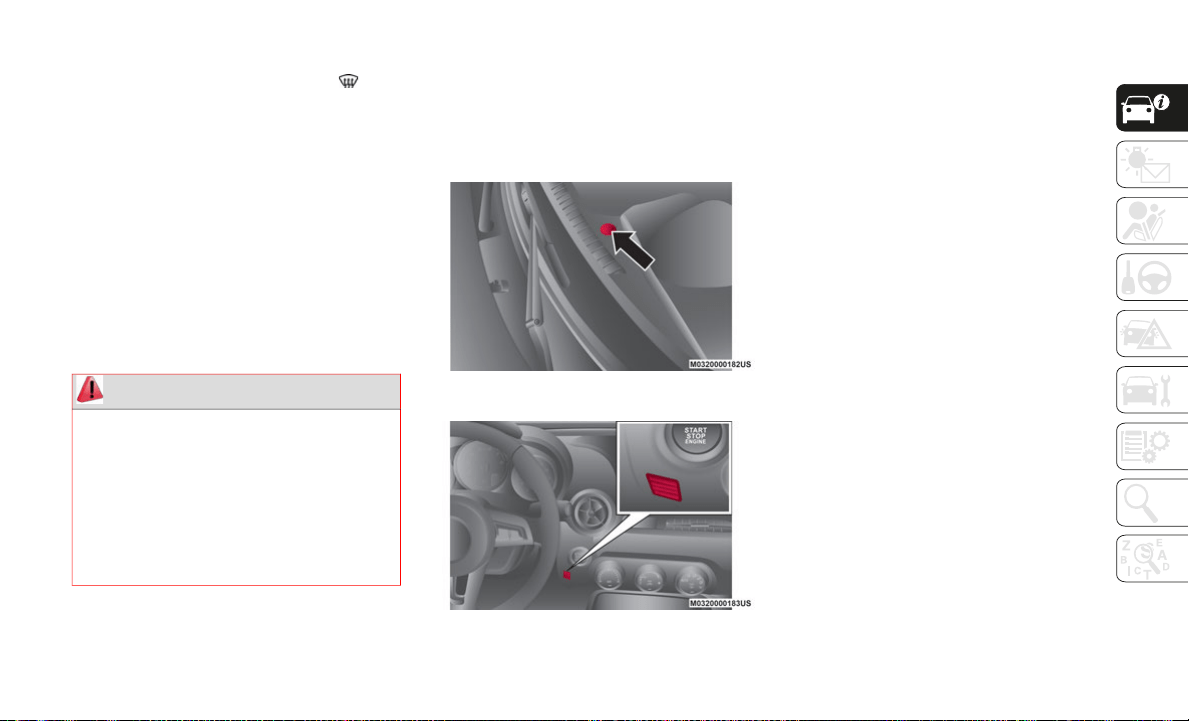
57
Windshield Defrosting And Defogging
Set the mode selector knob to the posi-
tion and turn the blower control knob to the
de
sired speed.
In this position, the outside air position is
au
tomatically selected, and when the blower
control knob is on, the air conditioner auto
-
matically turns on. The air conditioner will
di
rectly dehumidify the air to the front wind-
shield and side windows. Air flow amount
w
i
ll be increased.
Use the temperature control knob to increase
th
e air flow temperature and defog the wind-
shield more quickly.
Sunlight/Temperature Sensor
The air conditioning system measures inside
and outside temperatures, and sunlight.
It then sets temperatures inside the cabin
ac
cordingly.
Sunlight Sensor
Interior Temperature Sensor
NOTE:
Do not obstruct either sensor. Otherwise, the
ai
r-conditioning system will not operate
properly.
POWER WINDOWS
Power Window Controls
The ignition must be in the ON position for
the power windows to operate.
A power window may no longer open/close if
yo
u continue to push the switch after
opening/closing the power window.
If the power window does not open/close,
wa
it a moment and then operate the switch
again.
NOTE:
To prevent burning out the fuse and
da
maging the power window system, do not
open or close both windows at once.
The passenger window can be operated with
ea
ch door switch when the power window
lock switch on the driver's door is in the
unlocked position.
WARNING!
Set the temperature control to the hot or
warm position when defogging (Front
Defrost position). Using the Front Defrost
position with the temperature control set
to the cold position is dangerous as it will
cause the outside of the windshield to fog
up. Your vision will be hampered, which
could lead to a serious accident.
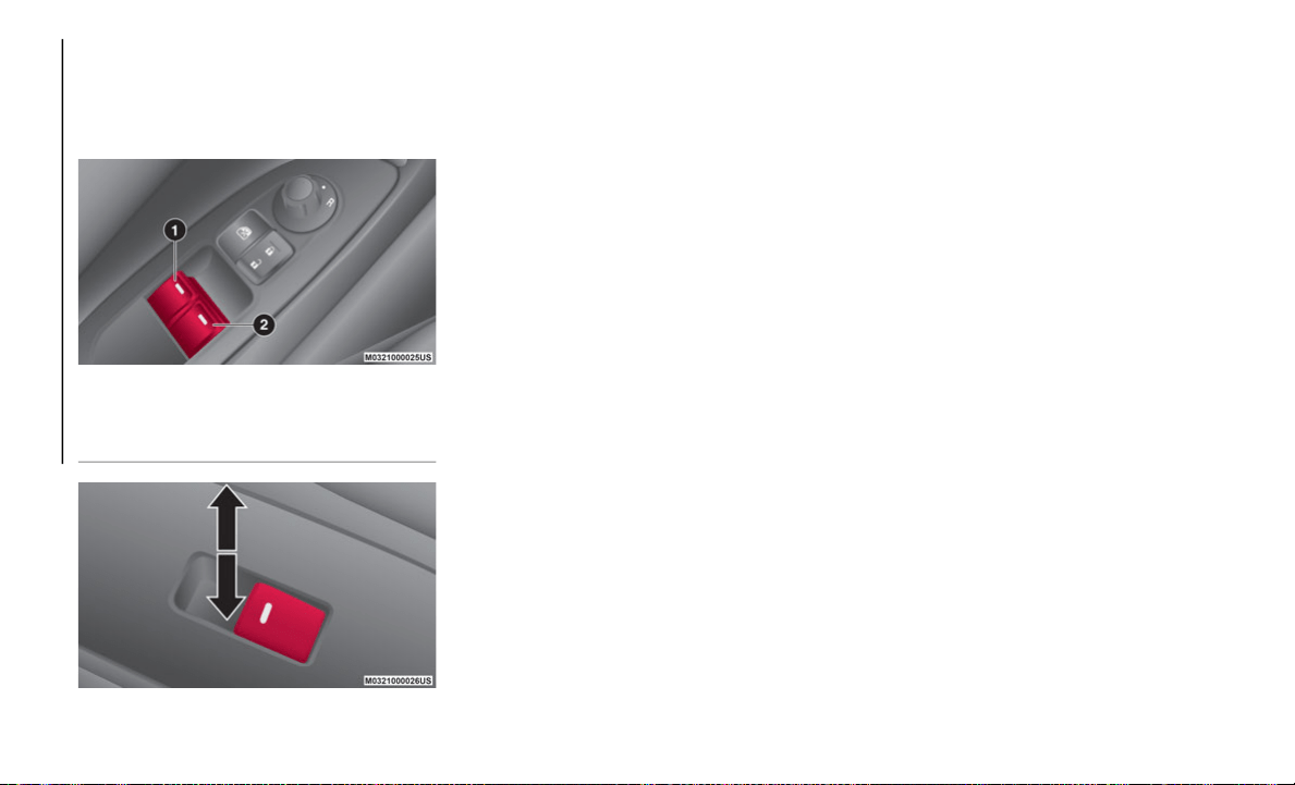
GETTING TO KNOW YOUR VEHICLE
58
Passenger Control Switches
The passenger window can also be operated
us
ing the master control switches on the
driver's door.
Power Window Switches
Power Window Switch Function
Auto-Opening Power Windows
To fully open the window automatically push
t
he switch completely down. To stop the
window partway pull or push the switch in
the opposite direction and then release it.
The power window cannot be fully closed
while the door is open.
Power Window System Initialization Procedure
If the battery was disconnected during
ve
hicle maintenance, or for other reasons
(such as a switch continues to be operated
after the window is open/closed), the window
will not fully open automatically.
Resetting of the automatic function can be
pe
rformed using the master control switches
or each passenger door switch.
The power window auto function reset proce-
dure can be done on both door switches. The
po
wer window auto function will only resume
on the power window that has been reset:
1. Close the doors and the convertible top.
2
. Place the ignition in the ON position.
3
. Make sure that the power window lock
s
witch located on the driver's door is not
depressed.
4. Push the switch and fully open the
w
indow.
5. Pull up the switch to fully close the
w
indow and continue holding the switch
for about two seconds after the window
fully closed.
6. Repeat steps four and five for the
p
assenger power window while seated in
the passenger seat.
7. Make sure that the power windows
o
perate correctly using the door switches.
After the system has been re-initialized,
pa
ssenger window can be fully opened auto-
matically using the master control switches.
I
f
the automatic power window operation
does not operate normally while the doors or
convertible top are opened/closed, reset it
using the above procedures.
Engine-Off Power Window Operation
The power window can be operated for about
40
seconds after the ignition has been
cycled from the ON to the OFF position with
both doors closed. If any door is opened, the
power window will stop operating.
1 — Driver's Window Switch
2 — Passenger's Window Switch
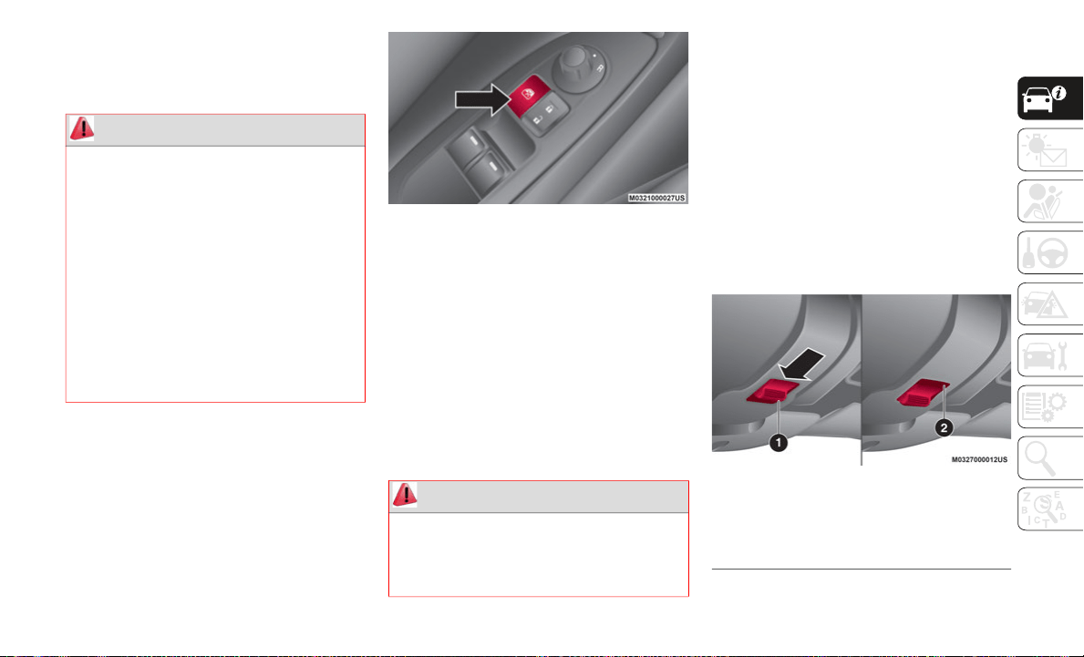
59
For engine-off operation of the power
window, the switch must be held up firmly
throughout window closure because the
auto-closing function will be inoperable.
Power Window Lock Switch
This feature prevents the passengers power
window from operating. Keep this switch in the
locked position while children are in the vehicle.
Locked Position (Button Pushed): only the
driver's power window can be operated.
Unlocked Position (Button Not Pushed): both
power windows on each door can be operated.
Power Window Lockout Switch
NOTE:
When the power window lock switch is in the
l
o
cked position, the light on the passenger
power window switch turns off. The light may
be difficult to see depending on the
surrounding brightness.
CONVERTIBLE TOP (SOFT
TOP)
Lowering The Convertible Top
To lower the convertible top, proceed as
follows:
1. Make sure the parking brake is applied
a
nd the ignition is placed in the OFF
position.
2. Make sure there are no objects which
h
ave been placed in the area where the
convertible top is to be retracted.
3. Push forward on the release latch. There
i
s a red indicator showing that the latch
is open.
Lock Release Latch
WARNING!
Never leave children unattended in a
vehicle, and do not let children play with
power windows. Do not leave the key fob in
or near the vehicle, or in a location
accessible to children, and do not leave
the ignition of a vehicle equipped with the
Keyless Entry System in the ACC or ON/
RUN mode. Occupants, particularly
unattended children, can become
entrapped by the windows while operating
the power window switches. Such
entrapment may result in serious injury or
death.
WARNING!
Do not sit on the folded convertible top,
otherwise the convertible top could be
damaged or you may fall off and be
injured.
1 — Release Latch Closed
2 — Release Latch Open (Red Indicator
Visible)
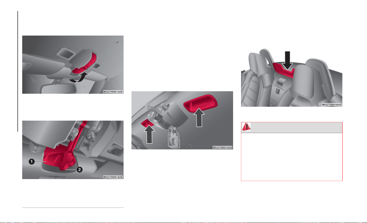
GETTING TO KNOW YOUR VEHICLE
60
(Continued)
4. With the lock release latch pushed
forward (red indicator visible), pull the
top latch handle rearward to unlock it.
Pulling The Top Latch Handle Rearward
5. R
emove the striker from the anchor.
R
emoving Striker From Anchor
NOTE:
The power windows will go down automati-
cally when the convertible top is opened. If
t
h
e power windows do not go down automat-
ically, fully open the windows using the
p
o
wer window switch located on the doors.
6. Standing outside of the vehicle, hold the
c
onvertible top along the front edge and
pull it toward the rear of the vehicle. To
lower the convertible top from inside the
vehicle, use the convertible top handles.
Convertible Top Handles
7. Move the convertible top rearward while
p
ushing the rear glass lightly with your
hand.
8. With the back end of the convertible top
p
ushed down, push the front end until a
latching sound is heard. Lightly rock the
retracted convertible top to make sure it
is securely locked.
Retracted Convertible Top
1 — Anchor
2 — Striker
WARNING!
Always keep your hands and fingers away
from the fastening mechanisms when
moving the convertible top: it is
dangerous to place your hands or fingers
near the fastening mechanisms. Your
hands or fingers could be caught and
injured by the mechanism.
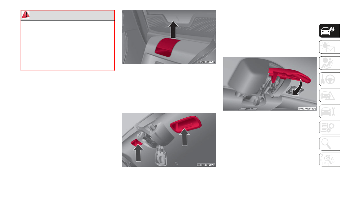
61
Raising The Convertible Top
To raise the convertible top, proceed as
follows:
1. Make sure the parking brake is applied
a
nd the ignition is placed in the OFF
position.
2. Pull the unlock lever upward to disen-
g
age the lock.
Unlock Lever
3. S
tanding outside of the vehicle, hold the
c
onvertible top along the front edge and
pull it towards the vehicle front. To raise
the convertible top from inside the
vehicle, use the convertible top handles.
Convertible Top Handles
4. While sitting in a seat, grasp the convert-
i
ble top handles, and push the convert-
ible top against the windshield. Make
s
u
re the striker engages with the anchor,
move the top latch slowly, and then push
the top latch upward until a latching
sound is heard.
Pull Top Latch Handle Forward
Sit in the seat with the seat belt correctly
fastened when the vehicle is moving:
standing in the vehicle, or sitting on the
convertible top storage area or center
console when the vehicle is moving is a
dangerous way to ride. During a sudden
maneuver or collision you could be seri
-
ously injured or even killed.
WARNING! (Continued)
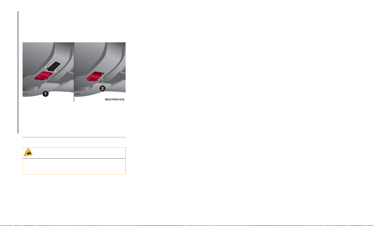
GETTING TO KNOW YOUR VEHICLE
62
5. If the red indicator is visible on the lock
release button, the convertible top is not
locked. After locking the convertible top,
verify that the red indicator is not visible.
Lock Release Button
NOTE:
Do not spray water directly near the seam
of the window and convertible top when
flushing away dirt on the soft top with
water. Otherwise, water may enter the
vehicle. Refer to “Convertible Top Mainte
-
nance” in “Servicing And Maintenance”.
The convertible top may be constricted if
it is left retracted for a long period. There-
fore, if the top has become constricted, it
m
a
y be difficult to hook the top latch
striker to the anchor.
Make sure the convertible top is securely
locked by pushing up on it. If it still
sounds loose (rattles) after being locked
by the top latch, contact an authorized
dealer.
Convertible Top Precautions
Remove leaves or other debris that may
accumulate on and around the convertible
top. If leaves or other debris block the
drain filter, water may enter the vehicle.
Clean the drain filter at least once a year.
Before lowering or raising the convertible
top, stop in a safe place off of the road and
park on a level surface.
When lowering the convertible top, make
sure objects inside the vehicle are not
blown away by the wind.
Secure all loose objects inside before
driving with the convertible top down.
To help prevent theft or vandalism and to
ensure that the passenger compartment
stays dry, close the convertible top
securely and lock both doors when leaving
the vehicle.
The soft top is made of high quality mate-
rial and if it is not maintained correctly,
th
e material could harden, becomes
stained, or have an uneven gloss.
Lowering the convertible top while it's wet
can also cause water to drip into the cabin.
The power windows go down automatically
in conjunction with the convertible top
opening/closing. However, this is a func
-
tion for improving the operability, and it
do
es not mean there is a problem. If the
vehicle battery is disconnected for vehicle
maintenance or other reasons, the power
windows will not go down automatically. If
the power windows do not go down, the
automatic open/close mechanism for the
windows must be reset.
1 — Release Latch Locked
2 — Release Latch Unlocked (Red Indica-
tor Visible)
CAUTION!
Driving with the convertible top not fully
locked could damage the convertible top.

63
(Continued)
The windblocker reduces the amount of
wind coming into the cabin from behind
when driving with the convertible top
opened.
Before starting the vehicle make sure the
convertible top is correctly locked.
HOOD
Opening The Hood
To open the hood, proceed as follows:
1. With the vehicle in PARK, pull the
r
elease handle located to the left of the
steering wheel, below the instrument
panel.
Releasing The Hood Latch
2. Move to the outside of the vehicle and
insert your hand into the hood opening,
then slide the latch lever to the right, and
lift up the hood.
Sliding The Latch Lever To The Right
3. P
ull up the support rod from the clip, and
i
nsert it into the support rod hole indi-
cated by the arrow to hold the hood open.
Support Rod
CAUTION!
Before opening the convertible top, make
sure the rear window defroster switch is
turned off. Otherwise the heat generated
from the window defroster could damage
the convertible top and the internal mate
-
rial.
Make sure nothing is on the convertible top
or near the back window when raising or
lowering the convertible top. Even small
objects may interfere and cause damage.
Do not drive through an automatic car
wash; it may damage the convertible top.
Do not raise or lower the convertible top
when the temperature is below 41°F (5°C);
this will damage the convertible top mate
-
rial.
Do not lower the convertible top when it's
wet. If the convertible top dries while
folded, it will deteriorate and mold.
Do not raise or lower the convertible top in
a strong wind as it could damage the
convertible top or cause an unexpected
accident.
CAUTION! (Continued)
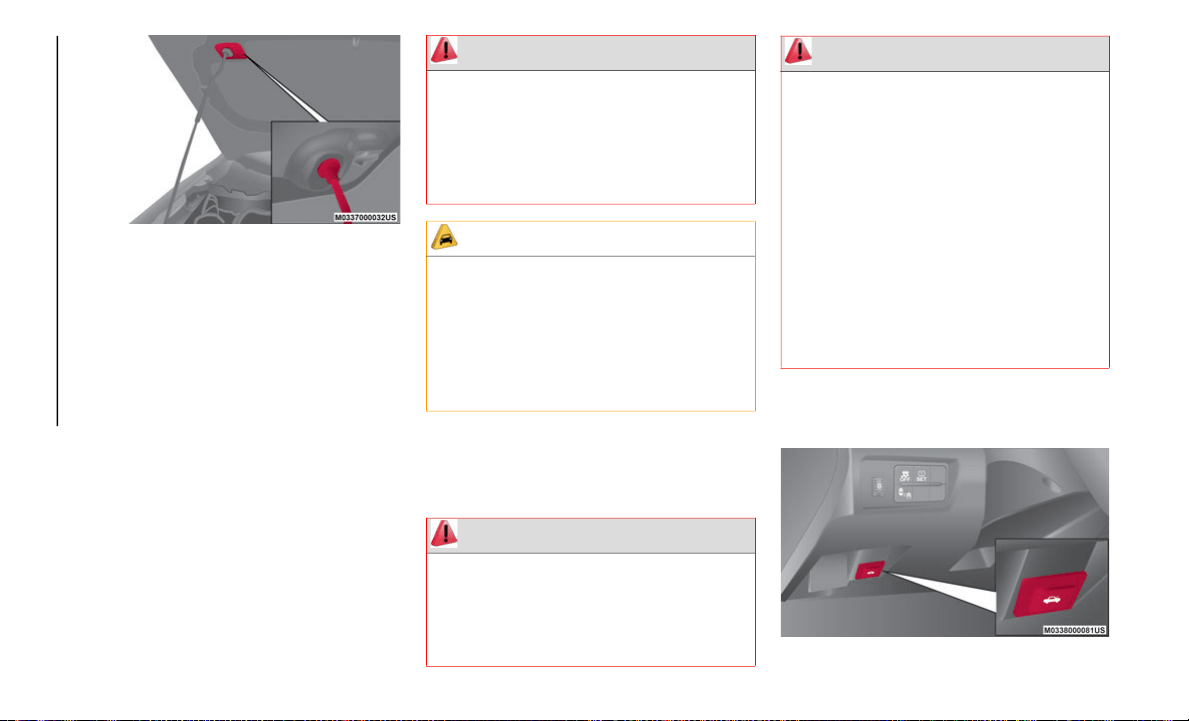
GETTING TO KNOW YOUR VEHICLE
64
(Continued)
Inserting Support Rod Into Hole
Closing The Hood
To close the hood, proceed as follows:
1. Check under the hood area to make
c
ertain all filler caps are in place and all
loose items (e.g. tools, oil containers,
etc.) have been removed.
2. Lift the hood with one hand, and with the
o
ther hand grasp the padded area on the
support rod.
3. Secure the support rod into the rod clip.
4
. Verify that the support rod is secured in
t
he clip before closing the hood.
5. Lower the hood slowly to a height of
a
bout 8 inches (20 cm) above its closed
po
sition and then let it drop.
TRUNK LID
Opening
Using The Remote Release Button — If
Equipped
Interior Trunk Lid Release Button
WARNING!
Be sure the hood is fully latched before
driving your vehicle. If the hood is not fully
latched, it could open when the vehicle is
in motion and block your vision. Failure to
follow this warning could result in serious
injury or death.
CAUTION!
To prevent possible damage, do not slam
the hood to close it. Lower hood to
approximately 8
inches (20 cm) and drop
th
e hood to close. Make sure hood is fully
closed for both latches. Never drive
vehicle unless hood is fully closed, with
both latches engaged.
WARNING!
Before opening the trunk lid, remove any
snow and ice accumulation on it. Other-
wise, the trunk lid could close under the
w
e
ight of the snow and ice resulting in
injury.
Be careful when opening/closing the
trunk lid during strong winds. If a strong
gust blows against the trunk lid, it could
close suddenly resulting in injury.
Fully open the trunk lid and make sure
that it stays open. If the trunk lid is only
opened partially, it could slam shut by
vibration or wind gusts resulting in
injury.
When loading or unloading luggage in
the trunk, turn off the engine. Otherwise,
you could get burned by the heat of the
exhaust gas.
WARNING! (Continued)
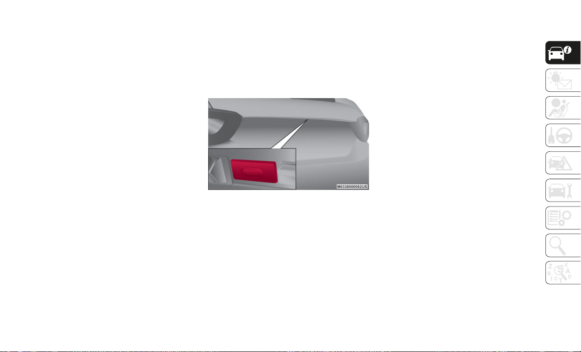
65
The remote release button function can be
disabled by locking the doors using the key
fob, emergency key, or a request switch on
the exterior door handle to prevent an
intruder in the vehicle from opening the
trunk lid.
To enable the remote release button opera-
tion, unlock the doors by using the key fob,
em
ergency key, request switch on the exte-
rior door handle, or place the ignition in the
O
N
position.
NOTE:
The remote release button cannot be
d
i
sabled by locking the doors using the
door-lock switch/door-lock knob.
Using The Electric Trunk Lid Opener
With the remote release button, the trunk lid
ca
n also be opened while the key fob is being
carried.
Push the electric trunk lid button and raise
th
e trunk lid when the latch releases.
Electric Trunk Release Button
Without the remote release button, unlock
th
e doors and trunk lid, then push the elec-
tric trunk lid opener and raise it when the
l
a
tch releases.
With The Advanced Keyless Entry Function
A locked trunk lid can also be opened while
th
e key fob is being carried. When opening
the trunk lid with the doors locked, it may
require a few seconds for the trunk lid latch
to release after the electric trunk lid opener
is pushed.
The trunk lid can be closed when the doors
ar
e locked with the key fob left in the vehicle.
However, to prevent locking the key fob in
the vehicle, the trunk lid can be opened by
pushing the electric trunk lid opener. If the
trunk lid cannot be opened despite doing
this procedure, push the electric trunk lid
opener to fully open the trunk lid after
pushing the trunk lid completely closed.
If the vehicle battery is depleted or there is a
ma
lfunction in the electrical system and the
trunk lid cannot be unlocked, the trunk lid
can be opened by performing the emergency
procedure.
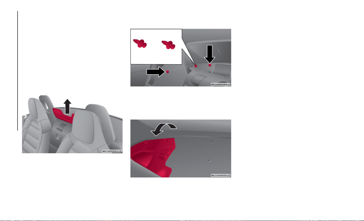
GETTING TO KNOW YOUR VEHICLE
66
When Trunk Lid Cannot Be Opened
If the battery is discharged, the trunk lid
cannot be unlocked and opened.
If the trunk lid cannot be unlocked even if
th
e discharged battery situation has been
resolved, the electrical system may have a
malfunction.
Proceed as follows:
1. Close the convertible top and remove the
w
indblocker.
Remove Windblocker
2. Remove the fasteners on the right side of
t
he vehicle.
Remove Fasteners
3. Partially peel back the cover on the right
s
ide of the vehicle.
Cover Removal
4. Turn and loosen the cap screws until the
s
crews start to spin free.
NOTE:
Do not pull the screw when pulling the cap.
Ot
herwise, the screw may fall off and
become lost.
Refer to “Trunk Emergency Release” in this
ch
apter for further information.
Closing
1. Use both hands to push the trunk lid
down until the lock snaps shut. Do not
slam it.
2. Pull up on the trunk lid to check if it is
s
ecure.
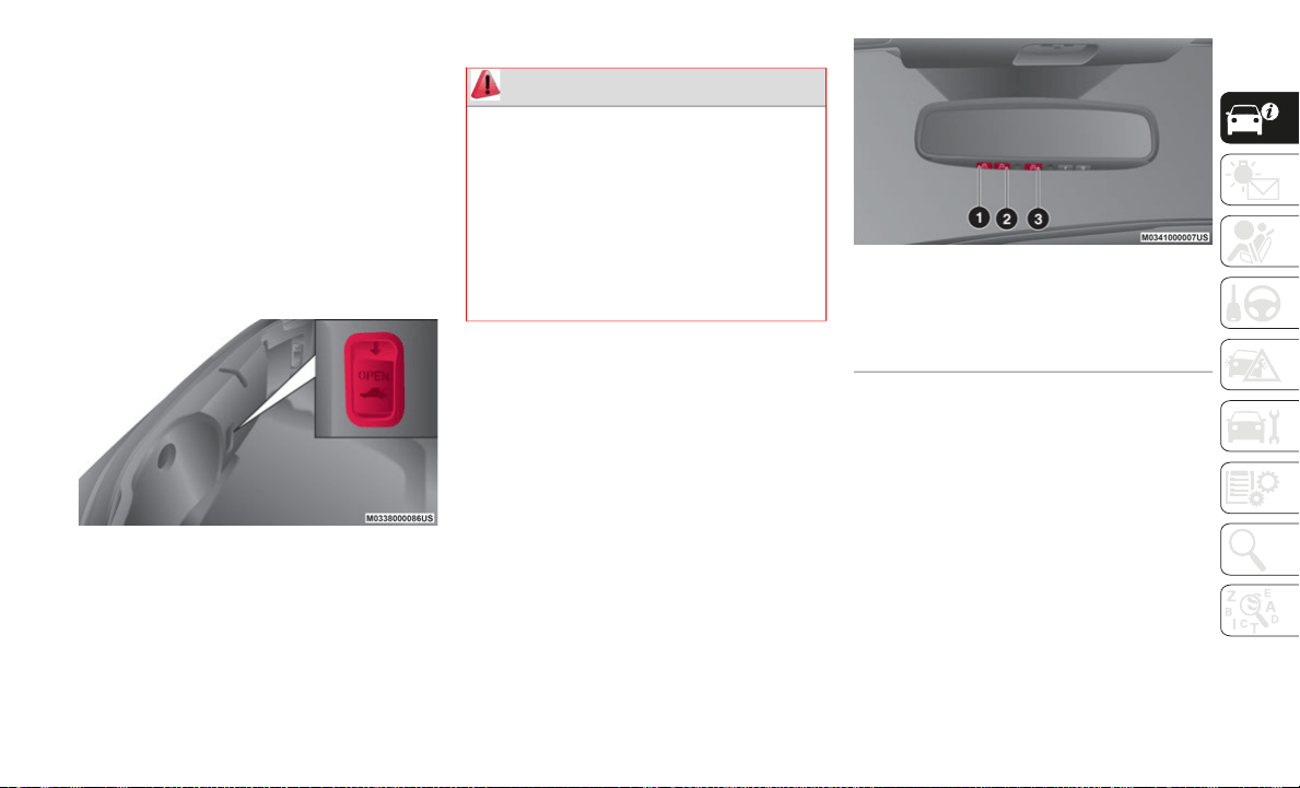
67
TRUNK EMERGENCY
RELEASE
As a security measure, a emergency release
lever is built into the rear tail panel of the
trunk. In the event of an adult or child being
locked inside the trunk, the trunk can be
simply opened by pulling down the lever and
open the trunk lid. After performing this
emergency measure, contact an authorized
dealer as soon as possible.
Trunk Emergency Release
Trunk Safety Warning
GARAGE DOOR OPENER —
IF EQUIPPED
HomeLink® replaces up to three hand-held
transmitters that operate devices such as
garage door openers, motorized gates,
lighting or home security systems. The
HomeLink® unit is powered by your vehicle’s
12 Volt battery.
The HomeLink® buttons, located on the
au
to-dimming mirror, designate the three
different HomeLink® channels. The Home
-
Link® indicator is located near the center
bu
tton.
HomeLink® Buttons
NOTE:
HomeLink® is disabled when the Vehicle
S
e
curity Alarm is active.
Before You Begin Programming
HomeLink®
Be sure that your vehicle is parked outside of
the garage before you begin programming.
For more efficient programming and accu-
rate transmission of the Radio Frequency
(
R
F) signal it is recommended that a new
battery be placed in the hand-held trans
-
mitter of the device that is being
pr
ogrammed to the HomeLink® system.
WARNING!
Do not allow children to have access to the
trunk, either by climbing into the trunk
from outside, or through the inside of the
vehicle. Always close the trunk lid when
your vehicle is unattended. Once in the
trunk, young children may not be able to
escape, even if they entered through the
rear seat. If trapped in the trunk, children
can die from suffocation or heat stroke.
1 — Homelink® Button 1
2 — Homelink® Button 2
3 — Homelink® Button 3
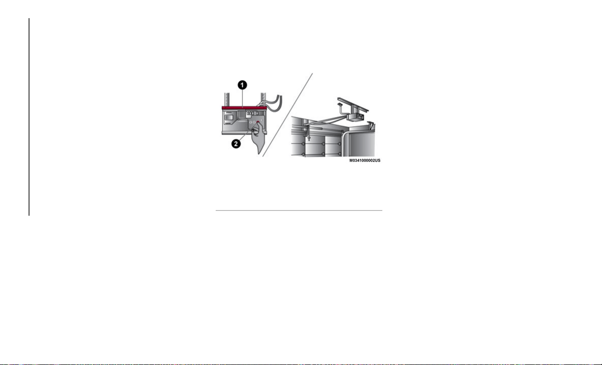
GETTING TO KNOW YOUR VEHICLE
68
To erase the channels, place the ignition in
the ON position, and push and hold the two
outside HomeLink® buttons (1 and 3) for up
to 20 seconds or until the orange indicator
flashes.
NOTE:
Erasing all channels should only be
performed when programming Home-
Link® for the first time. Do not erase
c
h
annels when programming additional
buttons.
If you have any problems, or require assis-
tance, please call toll-free
1-
800-355-3515 or, on the Internet at
HomeLink.com for information or assis-
tance.
Programming A Rolling Code
Garage door openers that were manufactured
after 1995 can be identified by the
“LEARN” or “TRAIN” button located where
the hanging antenna is attached to the
garage door opener.
NOTE:
It is NOT the button that is normally used to
op
en and close the door. The name and color
of the button may vary by manufacturer.
Training The Garage Door Opener
For programming these garage door openers,
pr
oceed as follows:
1. Place the ignition in the ON position.
2
. Place the hand-held transmitter 1 to
3
inches (3 to 8 cm) away from the
Ho
meLink® button you wish to program
while keeping the HomeLink® indicator
light in view.
3. Push and hold the HomeLink® button
y
ou want to program while you push and
hold the hand-held transmitter button.
4. Continue to hold both buttons and
o
bserve the indicator light. The Home-
Link® indicator will flash slowly and then
r
a
pidly after HomeLink® has received
the frequency signal from the hand-held
transmitter. Release both buttons after
the indicator light changes from slow to
rapid.
5. On the garage door opener (in the
g
arage), locate the “LEARN” or
“TRAINING” button. This can usually be
found where the hanging antenna wire is
attached to the garage door opener/
device motor. Firmly push and release
the “LEARN” or “TRAINING” button. On
some garage door openers/devices there
may be a light that blinks when the
garage door opener/device is in the
LEARN/TRAIN mode.
NOTE:
You have 30 seconds in which to initiate the
n
e
xt step after the LEARN button has been
pushed.
1 — Door Opener
2 — Training Button

69
6. Return to the vehicle and push the
programmed HomeLink® button twice
(holding the button for two seconds each
time). If the garage door opener/device
activates, programming is complete.
To program the remaining two Home-
Link® buttons, repeat each step for each
re
maining button. DO NOT erase the
channels.
NOTE:
If the garage door opener/device does not
ac
tivate, push the button a third time (for
two seconds) to complete the training.
Reprogramming A Single HomeLink® Button
(R
olling Code)
To reprogram a channel that has been previ-
ously trained, follow these steps:
1. P
lace the ignition in the ON position.
2
. Push and hold the desired HomeLink®
b
utton until the indicator light begins to
flash after 20 seconds. Do not release
the button.
3. Without releasing the button proceed
w
ith “Programming A Rolling Code” step
2 and follow all remaining steps.”
Programming A Non-Rolling Code
For programming garage door openers manu-
factured before 1995:
1. Place the ignition in the ON position.
2
. Place the hand-held transmitter 1 to
3
inches (3 to 8 cm) away from the
Ho
meLink® button you wish to program
while keeping the HomeLink® indicator
light in view.
3. Press and hold the HomeLink® button
y
ou want to program while you press and
hold the hand-held transmitter button.
4. Continue to hold both buttons and
o
bserve the indicator light. The Home-
Link® indicator will flash slowly and then
r
a
pidly after HomeLink® has received
the frequency signal from the hand-held
transmitter. Release both buttons after
the indicator light changes from slow to
rapid.
5. Press and hold the programmed Home-
L
ink® button and observe the indicator
li
ght.
If the indicator light stays on
constantly, programming is complete
and the garage door/device should
activate when the HomeLink® button
is pressed.
To program the two remaining Home-
Link® buttons, repeat each step for
each remaining button. DO NOT erase
the channels.
Reprogramming A Single HomeLink® Button
(N
on-Rolling Code)
To reprogram a channel that has been previ-
ously trained, follow these steps:
1. P
lace the ignition in the ON position.
2
. Press and hold the desired HomeLink®
b
utton until the indicator light begins to
flash after 20 seconds. Do not release
the button.
3. Without releasing the button, proceed
w
ith “Programming A Non-Rolling Code”
step 2 and follow all remaining steps.
Canadian/Gate Operator Programming
The programming of transmitters in Canada/
United States require the transmitter signals
to “time-out” after several seconds of trans
-
mission.

GETTING TO KNOW YOUR VEHICLE
70
Canadian radio frequency laws require trans-
mitter signals to time-out (or quit) after
se
veral seconds of transmission – which may
not be long enough for HomeLink® to pick
up the signal during programming. Similar to
this Canadian law, some U.S. gate operators
are designed to time-out in the same
manner.
It may be helpful to unplug the device during
th
e cycling process to prevent possible over-
heating of the garage door or gate motor.
1. P
lace the ignition in the ON position.
2
. Place the hand-held transmitter 1 to
3
inches (3 to 8 cm) away from the
Ho
meLink® button you wish to program
while keeping the HomeLink® indicator
light in view.
3. Continue to press and hold the Home-
L
ink® button, while you press and
re
lease (cycle) your hand-held trans-
mitter every two seconds until Home-
Link® has successfully accepted the
f
r
equency signal. The indicator light will
flash slowly and then rapidly when fully
trained.
4. Watch for the HomeLink® indicator to
ch
ange flash rates. When it changes, it is
programmed. It may take up to 30 seconds
or longer in rare cases. The garage door
may open and close while you are program
-
ming.
5. P
ress and hold the programmed Home-
L
ink® button and observe the indicator
li
ght.
NOTE:
If the indicator light stays on constantly,
programming is complete and the garage
door/device should activate when the
HomeLink® button is pressed.
To program the two remaining HomeLink®
buttons, repeat each step for each
remaining button. DO NOT erase the chan
-
nels.
If you unplugged the garage door opener/
de
vice for programming, plug it back in at
this time.
Reprogramming A Single HomeLink® Button
(C
anadian/Gate Operator)
To reprogram a channel that has been previ-
ously trained, follow these steps:
1. P
lace the ignition to the ON position.
2
. Press and hold the desired HomeLink®
b
utton until the indicator light begins to
flash after 20 seconds. Do not release
the button.
3. Without releasing the button, proceed
w
ith “Canadian/Gate Operator Program-
ming” step 2 and follow all remaining
s
t
eps.
Using HomeLink®
To operate, push and release the
programmed HomeLink® button. Activation
will now occur for the programmed device
(i.e. garage door opener, gate operator, secu
-
rity system, entry door lock, home/office
li
ghting, etc.). The hand-held transmitter of
the device may also be used at any time.
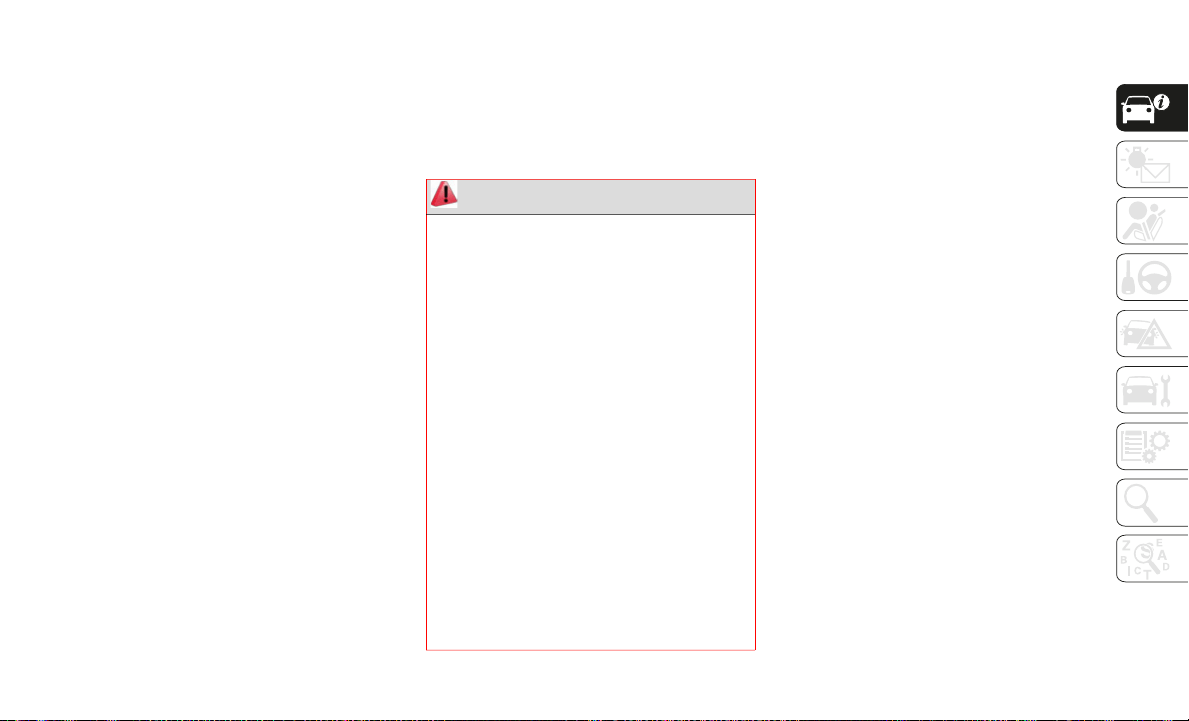
71
Security
It is advised to erase all channels before you
sell or turn in your vehicle.
To do this, push and hold the two outside
bu
ttons for 20 seconds until the orange indi-
cator flashes. Note that all channels will be
e
r
ased. Individual channels cannot be
erased.
The HomeLink® Universal Transceiver is
di
sabled when the Vehicle Security Alarm is
active.
NOTE:
The universal garage door opener only oper-
ates when the engine is running for security
re
asons associated with removable tops and
doors.
Troubleshooting Tips
If you are having trouble programming
HomeLink®, here are some of the most
common solutions:
Replace the battery in the garage door
opener hand-held transmitter.
Push the LEARN button on the garage
door opener to complete the training for a
Rolling Code.
Did you unplug the device for program-
ming and remember to plug it back in?
If you have any problems, or require assis-
tance, please call toll-free 1-800-355-3515
o
r
, on the Internet at HomeLink.com for
information or assistance.
General Information
The following regulatory statement applies to
all Radio Frequency (RF) devices equipped
in this vehicle:
This device complies with Part 15 of the FCC
Ru
les and with Innovation, Science and
Economic Development Canada
license-exempt RSS standard(s). Operation
is subject to the following two conditions:
1. This device may not cause harmful inter-
f
erence, and
2. This device must accept any interference
r
eceived, including interference that may
cause undesired operation.
Le présent appareil est conforme aux CNR
d`
Innovation, Science and Economic Devel-
opment applicables aux appareils radio
e
x
empts de licence. L'exploitation est
autorisée aux deux conditions suivantes:
1. l'appareil ne doit pas produire de brouil-
l
age, et
2. l'utilisateur de l'appareil doit accepter
t
out brouillage radioélectrique subi,
même si le brouillage est susceptible
d'en compromettre le fonctionnement.
WARNING!
Vehicle exhaust contains carbon
monoxide, a dangerous gas. Do not run
your vehicle in the garage while program
-
ming the transceiver. Exhaust gas can
ca
use serious injury or death.
Your motorized door or gate will open
and close while you are programming the
universal transceiver. Do not program
the transceiver if people, pets or other
objects are in the path of the door or
gate. Only use this transceiver with a
garage door opener that has a “stop and
reverse” feature as required by Federal
safety standards. This includes most
garage door opener models manufac
-
tured after 1982. Do not use a garage
do
or opener without these safety
features. Call toll-free 1-800-355-3515
or, on the Internet at
HomeLink.com for
safety information or assistance.
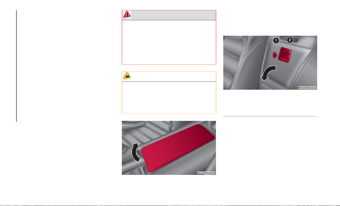
GETTING TO KNOW YOUR VEHICLE
72
La operación de este equipo está sujeta a las
siguientes dos condiciones:
1. es posible que este equipo o dispositivo
n
o cause interferencia perjudicial y
2. este equipo o dispositivo debe aceptar
c
ualquier interferencia, incluyendo la
que pueda causar su operación no
deseada.
NOTE:
Changes or modifications not expressly
a
p
proved by the party responsible for compli-
ance could void the user’s authority to
o
p
erate the equipment.
INTERNAL EQUIPMENT
Storage Compartments
Center Console
The center console is located between the
dr
iver’s and passenger’s seats.
Center Console Lid
Seat Side Compartment
The seat side compartment is located
be
tween the seats above the cupholders.
Seat Side Compartment
To open, push the release handle down to
open the seat side compartment.
Insert the emergency key in the lock and turn
it
clockwise to lock, counter clockwise to
unlock.
NOTE:
When using the rear console cup holders,
re
move any cups before opening the seat
side compartment. If the seat side compart
-
WARNING!
Keep storage compartments closed when
driving. Driving with the storage
compartments open is dangerous. To
reduce the possibility of injury in an
accident or a sudden stop, keep the
storage compartments closed when
driving.
CAUTION!
Do not leave lighters or eyeglasses in the
storage compartments while parked under
the sun. A lighter could explode or the
plastic material in eyeglasses could
deform and crack from high temperature.
1 — Key Hole
2 — Release Handle
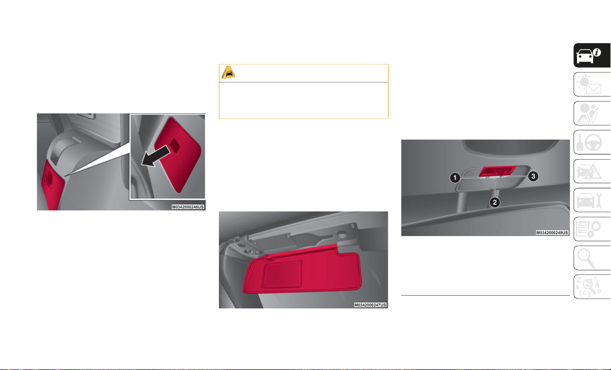
73
ment is opened with a cup present, the lid
will hit the cups and may cause the contents
to spill.
Back Trim Storage Compartment
Small items can be stored in the back trim
st
orage compartment which is located
behind the seats.
Back Trim Storage Compartment
To use the back trim storage compartment,
s
l
ide the seat all the way forward and fold the
seat back forward, then open the compart
-
ment.
When finished, close the compartment and
re
turn the seat to its original position and
secure it.
After returning the seat to its original posi-
tion, make sure the seat is secured by
a
t
tempting to lightly move it forward and
rearward.
Sun Visors
The sun visors are located at the sides of the
interior rear view mirror. They can be
adjusted forward toward the windshield, and
sideways toward the side windows to block
sunlight.
Sun Visor
Vanity Mirrors
To access the vanity mirror, fold the sun visor
do
wn and lift the cover toward the seats.
Interior Lights
Overhead Light
The interior light is located in the headliner
in
between the sun visors. The interior light
can be set to three different positions.
Overhead Light Switch
CAUTION!
Do not forcefully push objects into the rear
storage compartment. Otherwise, the box
could be damaged.
1 — On
2 — Door
3 — Off
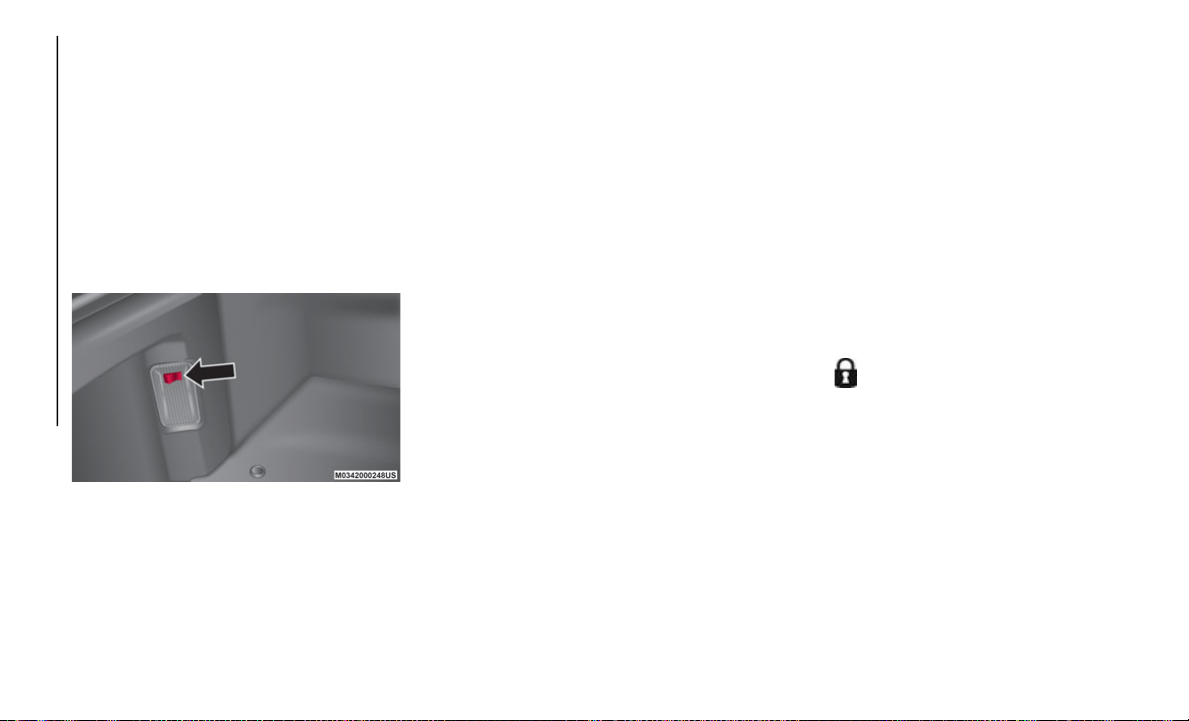
GETTING TO KNOW YOUR VEHICLE
74
Light switch positions:
On: Light is on at all times.
Door: Light is on when any door is open.
Light is on or off when the illuminated
entry system is on.
Off: Light is off at all times.
Trunk Light
The trunk light comes on when the lid is
op
en and turns off when closed.
Trunk Light Switch
NOTE:
To prevent the battery from being
d
i
scharged, do not leave the trunk open for a
long period when the engine is not running.
Illuminated Entry System
The overhead light turns on when any of the
fo
llowing operations occurs with the over-
head light switch in the door position and the
i
g
nition is OFF:
Turns on for about 30 seconds when the
driver's door is unlocked
Turns on for about 15 seconds when a
door is opened while a key fob is left in the
vehicle and then the door is closed
Turns on for about five seconds when a
door is opened from the outside with a key
fob being carried and then the door is
closed
The overhead lig ht turns on for ab ou t
15
second s when the ignition i s pla c ed
in the OF F position with the overhead
lig ht swi tch in the doo r position.
The overhead light turns off immediately in
th
e following cases:
The ignition is placed in the ON position,
and both doors are closed.
The driver's door is locked.
Battery Saver
If any door is left open with the overhead
l
i
ght switch in the door position or the trunk
lid is left open, the overhead light or trunk
light turns off after about 30
minutes to
pr
event discharge of the battery.
To prevent discharge of the battery, if the
in
terior lights remain on (the interior light
switch is in the on position), they will turn off
automatically under the following condi
-
tions:
No operations are done for about
30 minutes after the ignition is placed in
th
e OFF position.
The (lock) button on the key fob is
pushed, or the request switch located on
th
e exterior door handle is pushed to lock
the doors (vehicles with the advanced
keyless function) after the ignition is
placed in the OFF position.
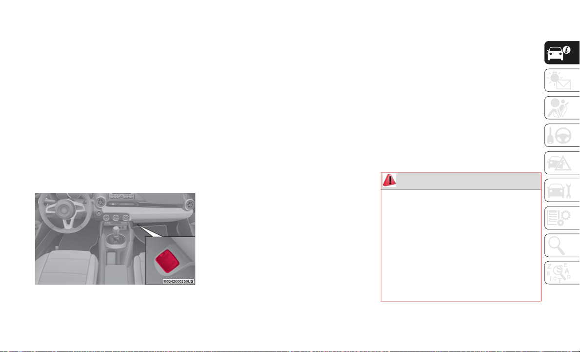
75
In addition, if the following operations are
performed after turning the interior lights off,
they will turn on again if:
The ignition is placed in a position other
than OFF.
A door is opened.
A door is unlocked.
The operation of the illuminated entry
sy
stem can be changed through the Connect
system.
Accessory Socket
The accessory socket is located deep in the
back of the footwell on the passenger side.
Accessory Socket
Only use genuine FCA accessories or the
eq
uivalent requiring no greater than 12V
(120 W, 10A).
The ignition must be in the ACC or ON posi-
tion.
To prevent accessory socket damage or elec-
trical failure, pay attention to the following:
Do not use accessories that require more
than 12V (120 W, 10A).
Do not use accessories that are not
genuine FCA accessories or the equiva-
lent.
Close the cover when the accessory socket
is not in use to prevent foreign objects and
liquids from getting into the accessory
socket.
Correctly insert the plug into the accessory
socket.
Do not insert the cigarette lighter into the
accessory socket.
Noise may occur on the audio playback
depending on the device connected to the
accessory socket.
Depending on the device connected to the
accessory socket, the vehicle's electrical
system may be affected, which could
cause the warning light to illuminate.
Disconnect the connected device and
make sure that the problem is resolved. If
the problem is resolved, disconnect the
device from the socket and place the igni
-
tion in the OFF position. If the problem is
no
t resolved, contact an authorized dealer.
NOTE:
To prevent discharging of the battery, do not
u
s
e the socket for long periods with the
engine off or idling.
WARNING!
To avoid serious injury or death:
Only devices designed for use in this
type of outlet should be inserted into any
12 Volt outlet.
Do not touch with wet hands.
Close the lid when not in use and while
driving the vehicle.
If this outlet is mishandled, it may cause
an electric shock and failure.
GETTING TO KNOW YOUR VEHICLE
76
Cupholders — If Equipped
Cupholders are available and can be inserted
in the center console on the passenger side
and the rear area of the center console.
Cupholders
Removing Cup Holders
Use both hands when removing the cup
ho
lder.
Removing Cupholders
Installing Cupholders
When installing a cupholder, insert it firmly
i
n
to the installation hole and make sure that
it is secured in place.
Installing Cupholders
The front cupholder can be removed and
in
stalled to the rear console.
Correct Cupholder Placement
1 — Rear Cup Holder (If Equipped)
2 — Front Cup Holder
WARNING!
Never use a cup holder to hold hot liquids
while the vehicle is moving. Using a cup
holder to hold hot liquids while the vehicle
is moving is dangerous. If the contents
spill, you could be burned.
CAUTION!
Do not place plastic bottles without caps
in the cup holders. Otherwise, the
contents may spill while the vehicle is
being driven.
Do not place excessive weight on the cup
holders such as by resting your hands or
elbows on them. Otherwise, the cup
holders could be damaged.
If a passenger is present, install the front
cup holder to the rear console. Other-
wise, a knee might hit it and cause the
c
o
ntents to spill.
1 — Front Cupholder
2 — Rear Cupholder
77
The rear cupholder is designed for use on the
rear console and cannot be installed to the
front side.
Incorrect Cupholder Placement
Windblocker
The Windblocker reduces rear wind coming
into the cabin while driving with the convert-
ible top in the lowered position.
Windblocker
ELECTRIC POWER
STEERING
Power Steering
Electric power steering is only operable when
the engine is running.
If the engine is off, or if the power steering
sy
stem is inoperable, steering the vehicle
will require more physical effort.
If the steering feels stiffer than usual during
no
rmal driving, or the steering vibrates,
contact an authorized dealer.
The warning light illuminated in the
instrument cluster display notifies the driver
o
f
system abnormalities and operation condi-
tions.
NOTE:
Never hold the steering wheel to the extreme
l
e
ft or right for more than five seconds with
the engine running. This could damage the
power steering system.
ENVIRONMENT
PROTECTION SYSTEMS
Emission Control System
This vehicle is equipped with an emission
control system (the catalytic converter is part
of this system) that enables the vehicle to
comply with existing exhaust emissions
requirements.
Ignoring the following precautions could
ca
use lead to accumulate on the catalyst
inside the converter or cause the converter to
get very hot. Either condition will damage the
converter and cause poor performance:
USE ONLY UNLEADED FUEL.
Do not drive the vehicle with any sign of
engine malfunction.
Do not coast with the ignition OFF.
Do not descend steep grades in gear with
the ignition OFF.
Do not operate the engine at high idle for
more than two minutes.

GETTING TO KNOW YOUR VEHICLE
78
Do not tamper with the emission control
system. All inspections and adjustments
must be made by an authorized dealer.
Do not push-start or pull-start your
vehicle.
Under U.S. federal law, any modification to
th
e original-equipment emission control
system before the first sale and registration
of a vehicle is subject to penalties. In some
states, such modification made on a used
vehicle is also subject to penalties.
While the engine is off, the sound of a valve
op
ening and closing can be heard at the rear
of the vehicle, however this does not indicate
an abnormality. The vehicle has a
self-checking device and it operates while
the engine is off.
WARNING!
A hot exhaust system can start a fire if you
park over materials that can burn. Such
materials might be grass or leaves coming
into contact with your exhaust system. Do
not park or operate your vehicle in areas
where your exhaust system can contact
anything that can burn.
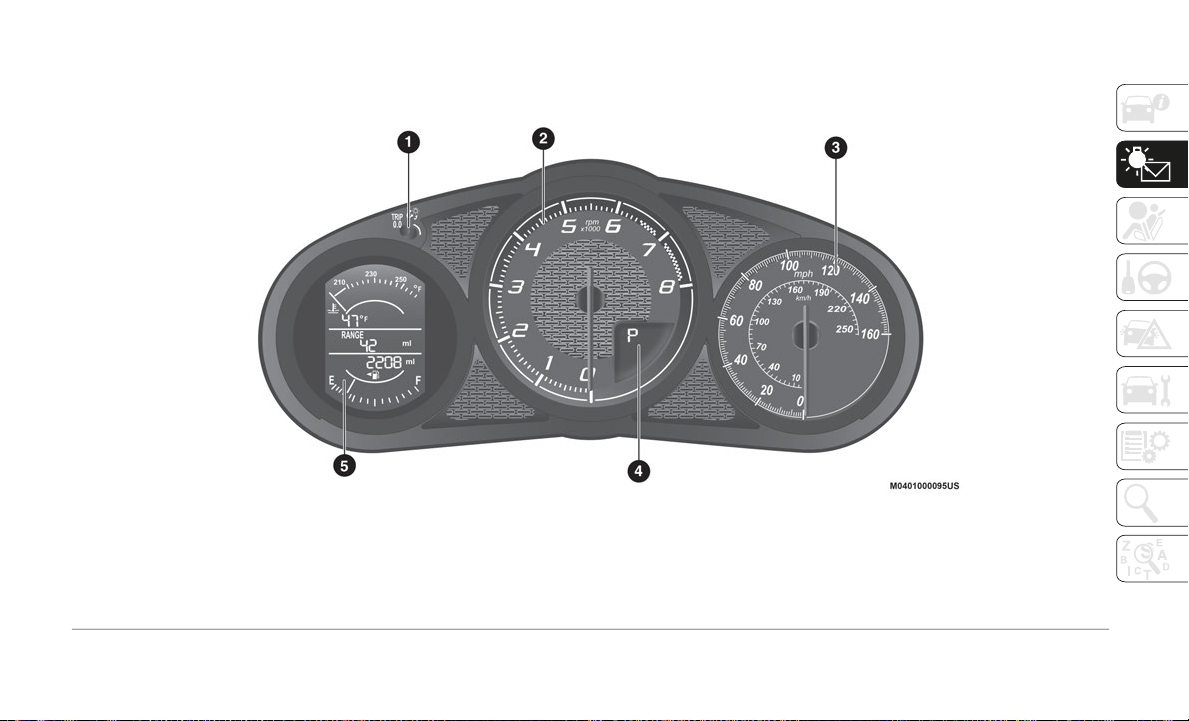
79
CONTROL PANEL AND INSTRUMENTS
Instrument Cluster
Abarth Instrument Cluster
1 — Odometer/Trip Computer And Trip Computer Button/Dashboard
Ill
umination
2 — Tachometer
3 — Speedometer
4 — Automatic Transmission Info Display
5 — Odometer/Trip Computer Info/Engine Coolant Temperature
Gau
ge/Fuel Gauge/Outside Temperature/Cruise Control/Info Switch
Display
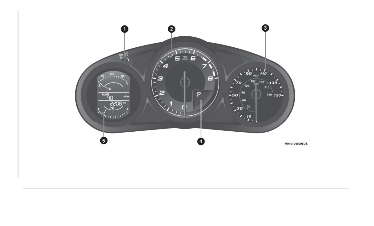
GETTING TO KNOW YOUR INSTRUMENT PANEL
80
Instrument Cluster
Instrument Cluster
1 — Odometer/Trip Computer And Trip Computer Button/Dashboard
Il
lumination
2 — Tachometer
3 — Speedometer
4 — Automatic Transmission Info Display
5 — Odometer/Trip Computer Info/Engine Coolant Temperature
Ga
uge/Fuel Gauge/Outside Temperature/Cruise Control/Info Switch
Display
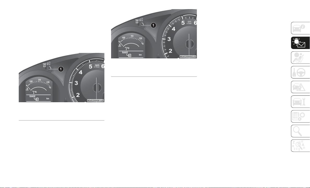
81
Odometer/Trip Computer
The display mode can be changed from
odometer to “Trip computer A” to “Trip
computer B” and then back to odometer by
pushing the selector.
The selected mode will be displayed.
Abarth Odometer/Trip Reset Button
Odometer/Trip Reset Button
Odometer
The odometer records the total distance the
ve
hicle has been driven.
Trip Computer
The trip computer can record the total
d
i
stance of two trips. One is recorded in
“Trip A”, and the other is recorded in “Trip
B”.
For instance, “Trip A” can record the
di
stance from the point of origin, and “Trip
B” can record the distance from where the
fuel tank is filled.
When “Trip A” is selected, pushing the
se
lector again within one second will change
to “Trip B” mode. When “Trip A” is selected,
TRIP A will be displayed. When “Trip B” is
selected, TRIP B will be displayed.
The trip computer records the total distance
th
e vehicle is driven until the meter is reset.
Return it to “0.0” by depressing and holding
the selector for one second or more.
Use this meter to measure trip distances and
to
compute fuel consumption.
NOTE:
Only the trip records tenths of miles (kilome-
ters).
Trip Computer Reset
The trip computer will be erased when:
The power supply is interrupted (blown
fuse or the battery is disconnected).
The vehicle is driven over 9999.9 miles.
Speedometer
The speedometer indicates the speed of the
vehicle.
1 — Odometer/Trip Reset Button
1 — Odometer/Trip Reset Button
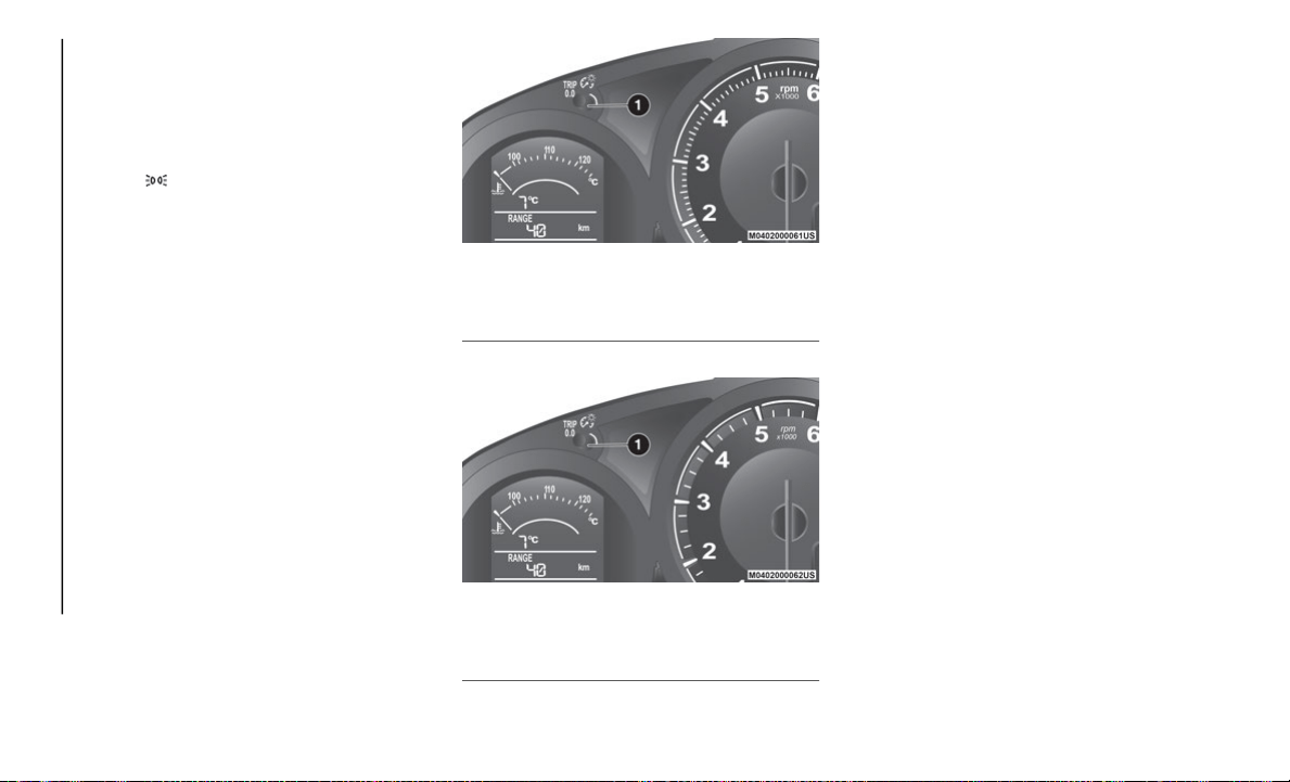
GETTING TO KNOW YOUR INSTRUMENT PANEL
82
Instrument Panel Illumination
When the position lights are turned on with
the ignition switched ON, the brightness of
the instrument panel illumination is
dimmed. When the position lights are turned
on, the
warning light in the instrument
cluster illuminates. See “Exterior Lights” in
“G
etting To Know Your Vehicle” chapter.
Brightness Adjustment
The brightness of the instrument panel and
d
a
shboard illuminations can be adjusted by
rotating the knob:
The brightness decreases by rotating the
knob to the left. A beep will be heard when
the knob has been rotated to the
maximum dim position.
The brightness increases by rotating the
knob to the right.
Abarth Dimmer Knob
Dimmer Knob
Canceling Illumination Dimmer
With the ignition ON, rotate the knob to the
ri
ght until a beep sounds while the instru-
ment cluster is dimmed. If the instrument
c
l
uster's visibility is reduced due to glare
from surrounding brightness, cancel the illu
-
mination dimmer.
When the illumination dimmer is canceled,
th
e instrument cluster cannot be dimmed
even if the position lights are turned on.
When the illumination dimmer is canceled,
the screen in the center display switches to
constant display of the daytime screen.
Trip Computer And Info Switch
The following information can be selected by
pushing the INFO switch with the ignition in
the ON position:
Distance-to-empty (approximate distance
you can travel on the available fuel)
Average fuel economy
Current fuel economy
1 — Instrument Cluster Illumination Dim-
mer Knob
1 — Instrument Cluster Illumination Dim-
mer Knob
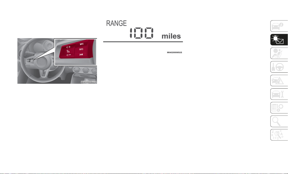
83
Average vehicle speed
Vehicle speed alarm — If Equipped
If you have any problems with your trip
co
mputer, contact an authorized dealer.
Instrument Cluster Display Controls
Distance-To-Empty Mode
This mode displays the approximate distance
y
o
u can travel on the remaining fuel based
on the fuel economy.
The distance-to-empty will be calculated and
di
splayed every second.
Distance To Empty Display Screen
NOTE:
Even though the distance-to-empty
display may indicate a sufficient amount
of remaining driving distance before refu
-
eling is required, refuel as soon as
po
ssible if the fuel level is very low or the
low fuel warning light illuminates.
The display may not change unless you
add more than approximately 2.3 gallons
(9 liters) of fuel.
The distance-to-empty is the approximate
remaining distance the vehicle can be
driven until all the graduation marks in the
fuel gauge (indicating the remaining fuel
supply) disappear.
If there is no past fuel economy informa-
tion such as after first purchasing your
ve
hicle or the information is deleted when
the battery cables are disconnected, the
actual distance-to empty/range may differ
from the amount indicated.
Average Fuel Economy Mode
This mode displays the average fuel economy
by
calculating the total fuel consumption
and the total traveled distance since
purchasing the vehicle, reconnecting the
battery after disconnection, or resetting the
data.
The average fuel economy is calculated and
di
splayed every minute. To clear the data
being displayed, push the INFO switch for
more than 1.5 seconds.
After pushing the INFO switch, “- - - mpg”
(“
- - - L/100 km”) will be displayed for about
on
e minute before the fuel economy is recal-
culated and displayed.
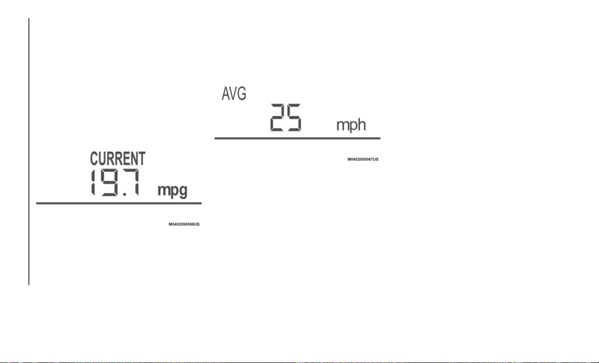
GETTING TO KNOW YOUR INSTRUMENT PANEL
84
Current Fuel Economy Mode
This mode displays the current fuel economy
by
calculating the amount of fuel consump-
tion and the distance traveled. Current fuel
e
c
onomy will be calculated and displayed
every two seconds.
When you've slowed to about 3 mph (5 km/h)
,
“- - - mpg” (“- - - L/100 km”) will be
di
splayed.
Current Fuel Economy Display Screen
Average Vehicle Speed Mode
This mode displays the average vehicle
s
p
eed by calculating the distance and the
time traveled since connecting the battery or
resetting the data.
Average vehicle speed will be calculated and
di
splayed every 10 seconds. To clear the
data being displayed, push the INFO switch
for more than 1.5 seconds.
Average Vehicle Speed Display Screen
After pushing the INFO switch, “- - - MPH”
(“
- - - km/h”) will be displayed for about one
minute before the vehicle speed is recalcu
-
lated and displayed.
Vehicle Speed Alarm Mode — If Equipped
In this mode, the current setting for the
Ve
hicle Speed Alarm is displayed. You can
change the set vehicle speed that will trigger
the warning.
NOTE:
The vehicle speed alarm display is activated
at
the same time the beep sound is heard.
The set vehicle speed will flash several
times. The vehicle speed alarm can be set
using the INFO switch. The vehicle speed
alarm function can be set between 18 and
155
mph (30 and 250 km/h).
NOTE:
Always set the vehicle speed according to the
l
a
ws and regulations of the country/city in
which the vehicle is driven. In addition,
always verify the speed of the vehicle using
the speedometer.
The vehicle speed alarm can be set using the
fo
llowing procedure:
1. Press the INFO switch to display the
V
ehicle Speed Alarm mode.
2. Press the INFO switch continuously until
a
beep sound is heard. The set vehicle
speed display flashes the first digit.
3. Press the INFO switch and set the first
d
igit to the desired vehicle speed. The
numerical value changes each time the
INFO switch is pressed.
4. Press the INFO switch continuously until
a
beep sound is heard. The set vehicle
speed display flashes the lower two
digits.
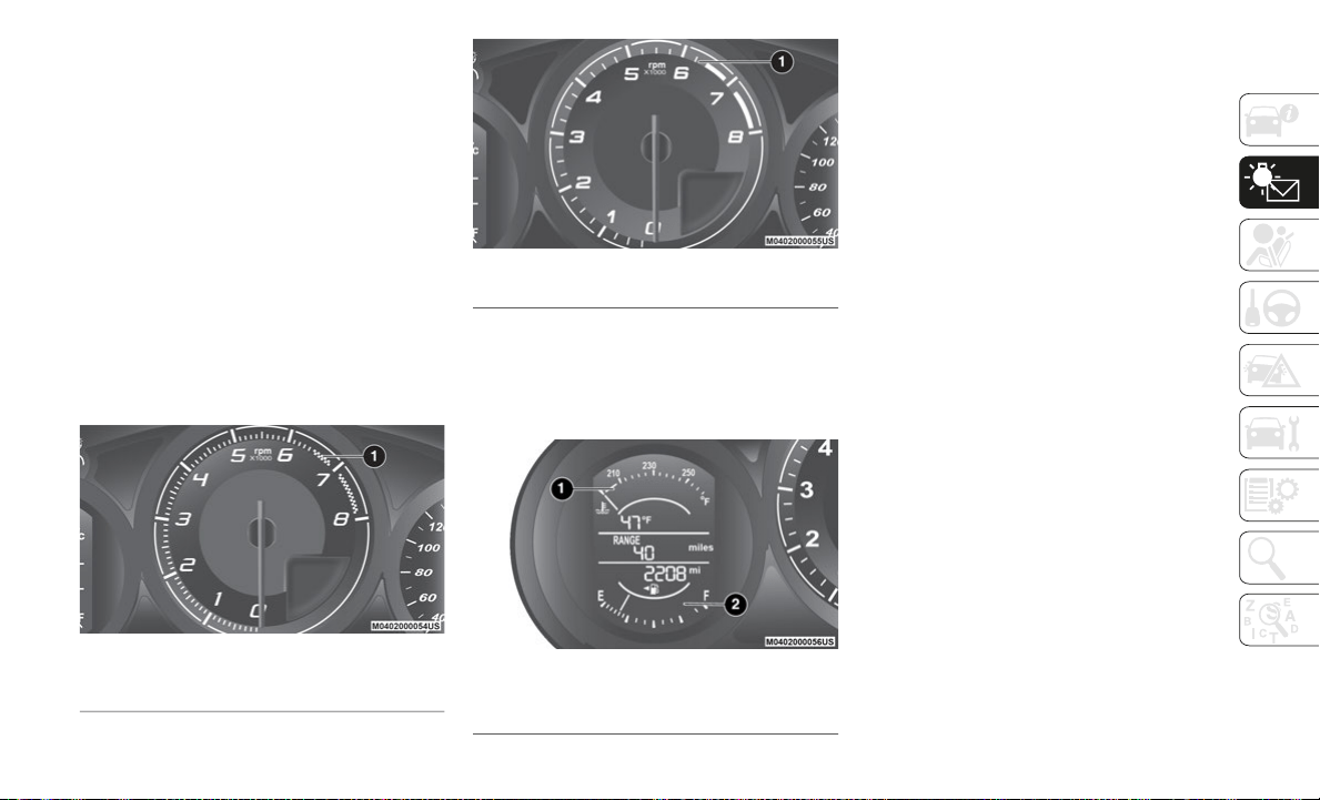
85
5. Press the INFO switch and set the two
lower digits to the desired vehicle speed.
The numerical value changes each time
the INFO switch is pressed.
6. Press the INFO switch continuously until
a
beep sound is heard. The set vehicle
speed is displayed on the vehicle speed
alarm screen.
Tachometer
The tachometer shows engine speed in thou-
sands of revolutions per minute (rpm).
The range varies depending on the type of
ga
uge.
Abarth Tachometer
Tachometer
Engine Coolant Temperature Gauge And
Fuel Gauge
Engine Coolant Temperature Gauge
Fuel/Temperature Gauge
NOTE:
If the high engine coolant temperature
wa
rning light (red) turns on, there is a possi-
bility of overheating. Park the vehicle in a
s
a
fe place immediately and take appropriate
measures. If the vehicle continues to be
driven, it could cause damage to the engine.
Fuel Gauge
The fuel gauge shows approximately how
mu
ch fuel is remaining in the tank when the
ignition is in the ON position. We recom
-
mend keeping the tank over a quarter full.
E = Empty
F = Full
If the low fuel warning light illuminates or
th
e fuel level is very low, refuel as soon as
possible.
NOTE:
After refueling, it may require some time
for the indicator to stabilize. In addition,
the indicator may deviate while driving on
a slope or curve since the fuel moves in
the tank.
1 — Tachometer Display
1 — Tachometer Display
1 — Engine Coolant Temperature
2 — Fuel Gauge
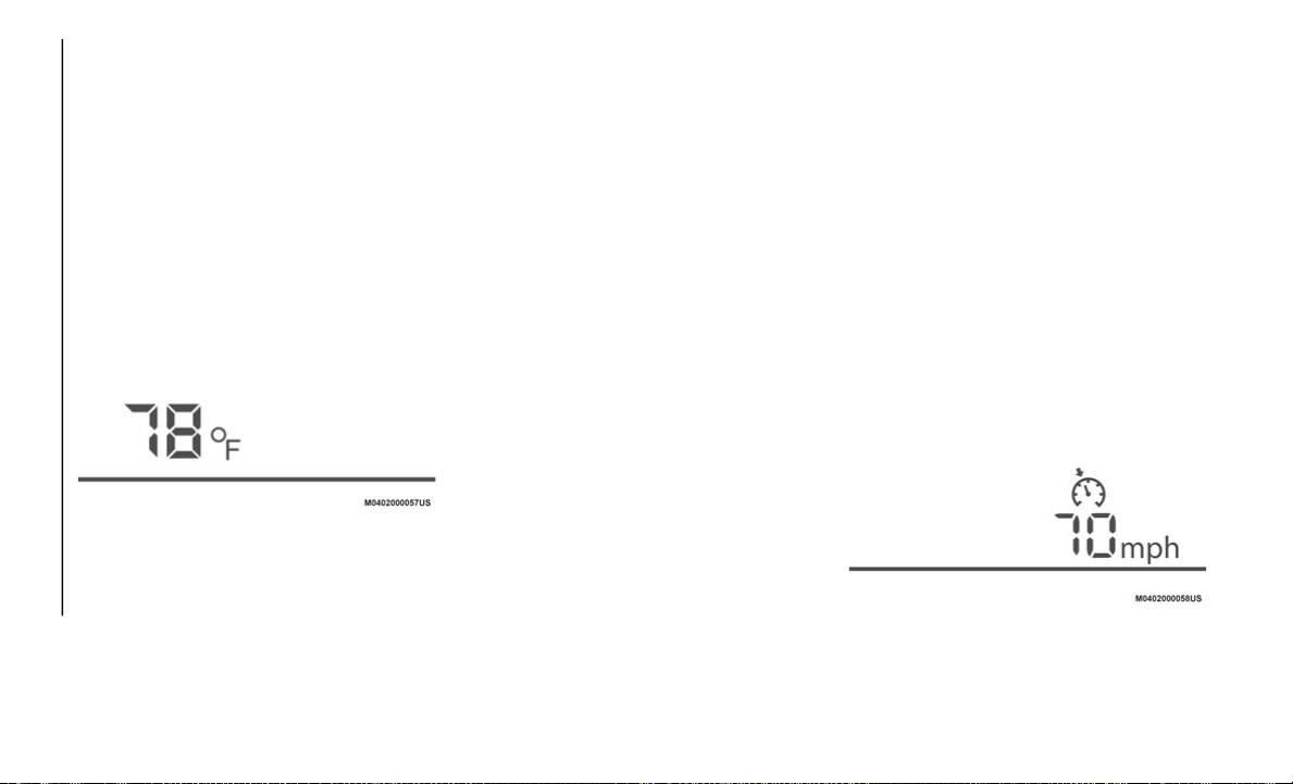
GETTING TO KNOW YOUR INSTRUMENT PANEL
86
The display indicating a quarter or less
remaining fuel has more segments to show
the remaining fuel level in greater detail.
The direction of the arrow on the fuel
gauge indicates that the fuel door lid is on
the left side of the vehicle.
Outside Temperature Display
When the ignition is in the ON position, the
outside temperature is displayed.
Outside Temperature Screen Display
Under the following conditions, the outside
t
e
mperature display may differ from the
actual outside temperature depending on the
surroundings and vehicle conditions:
Significantly cold or hot temperatures.
Sudden changes in outside temperature.
The vehicle is parked.
The vehicle is driven at low speeds.
Changing The Temperature Unit Of The Outside
Te
mperature Display
The outside temperature unit can be
sw
itched between Fahrenheit and Celsius
using the following procedure.
Vehicles With Fiat Connect 7.0
Settings can be changed through the
Co
nnect 7.0 radio screen. Refer to “Person-
alization Features” in this chapter.
Vehicles With Fiat Radio 3.0
Proceed as follows:
1. P
ush the INFO switch with the ignition in
t
he OFF position and continue pushing
the INFO switch for five seconds or
longer while placing the ignition in the
ON position. The outside temperature
display flashes.
2. Push the INFO switch to change the
o
utside temperature unit.
3. Push and hold the INFO switch for three
s
econds or longer while the outside
temperature display is flashing. The
outside temperature display illuminates.
NOTE:
When the temperature unit indicated in the
o
u
tside temperature display is changed, the
temperature unit indicated in the engine
coolant gauge display changes in conjunc
-
tion with it.
Cruise Control Set Vehicle Speed Display
The vehicle speed preset using the cruise
control is displayed.
Cruise Control Display Screen

87
Gear Shift Indicator — If Equipped
The gear shift indicator helps the driver
obtain optimum fuel economy and smooth
driving. It displays the selected Gear Position
1
in the instrument cluster and also notifies
th
e driver to change to the most suitable
Gear Position 2 corresponding to the actual
driving condition.
NOTE:
Do not rely solely on the shift-up/shift-down
re
commendations by indications. The actual
driving situation might require shift opera
-
tions different from indication. To avoid the
ri
sk of accidents, the road and traffic condi-
tions have to be judged correctly by the
d
r
iver before shifting.
Vehicles with Manual Transmission
The gear shift indicator turns off when the
f
o
llowing operations are performed:
The vehicle is stopped
The vehicle is put in neutral
The vehicle is driven in reverse
The clutch is not fully engaged when
accelerating
The clutch pedal remains depressed for
two seconds or longer while driving
Vehicles with Automatic Transmission
The gear shift indicator turns off when the
f
o
llowing operations are performed:
The vehicle is stopped
Manual shift mode is canceled
Manually Shifting Up (Versions with Automatic
Tr
ansmission)
Using the selector lever: to shift up to a
hi
gher gear, tap the selector lever back +
once.
MAINTENANCE MONITOR
— IF EQUIPPED
Oil Life Reset
Vehicles With Fiat Radio 3.0
“Oil Change” with flexible settings are avail-
able. Consult an authorized dealer for
de
tails.
NOTE:
The engine oil flexible maintenance setting
is
available (if equipped). Based on the
engine operating conditions, the on-board
computer in your vehicle calculates the
remaining oil life. When the engine oil flex
-
ible maintenance setting is selected, the
sy
stem must be reset whenever replacing the
engine oil.
When the engine oil flexible maintenance
se
tting is selected, the Indicator light will
illuminate in the instrument cluster when
remaining oil life becomes less than
300
miles (500 km) or remaining days are
le
ss than 15 (whichever comes first).
Reset Method
Your vehicle is equipped with an engine oil
change indicator system. The “Oil Change
Required” message will flash in the instrument
cluster display for approximately 10 seconds
after a single chime has sounded to indicate
the next scheduled oil change interval. The
engine oil change indicator system is duty cycle
based, which means the engine oil change
interval may fluctuate, dependent upon your
personal driving style.

GETTING TO KNOW YOUR INSTRUMENT PANEL
88
Unless reset, this message will continue to
display each time you turn the ignition
switch to the ON/RUN position. To reset the
oil change indicator system (after performing
the scheduled maintenance), refer to the
following procedure
1. Place the ignition in the ON position. (Do
n
ot start the engine.)
2. Fully push the accelerator pedal slowly to
t
he floor, three times within ten seconds.
3. Place the ignition in the OFF/LOCK posi-
t
ion.
NOTE:
If the indicator message illuminates when
y
o
u start the vehicle, the oil change indicator
system did not reset. If necessary, repeat
this procedure.
Oil Life Reset
Vehicles With FIAT Connect 7.0 Radio
Proceed as follows:
1. Select the icon
on the home screen to
display the “Applications” screen.
2. Select “Maintenance” to display the
m
aintenance list screen.
3. Switch the tab and select the setting
i
tem you want to change: “Scheduled,”
“Tire Rotation,” or “Oil Change.”
Oil Life Monitor
You can customize settings in the setup display as follows:
Tab Item Explanation
Scheduled Setting Notification can be turned on/off.
Time (months) Displays the time or distance until maintenance is due. Select this item to set the
ma
intenance period. “Scheduled Due!” is displayed in red, and the indicator light
will illuminate in the instrument cluster when the remaining distance is less than
300
miles (500 km) or the remaining number of days is less than 15 (whichever
co
mes first).
Distance (mile or km)
Reset Resets the time and distance to the initial values. Once the system turns on, it
ne
eds to be reset whenever carrying out maintenance.

89
(*) The engine oil flexible maintenance setting is available (only some models). Consult an authorized dealer for details. When the engine oil
flexible maintenance setting is selected, you will see the following items in the display.
The vehicle calculates the remaining oil life based on the engine operating conditions and lets you know when an oil change is due by illu-
minating the indicator light in the instrument cluster.
Tire Rotation Setting Notification can be switched on/off.
Distance (mile or km) Displays the distance until tire rotation is due. Select this item to set the tire
ro
tation distance. “Tire Rotation Due!” is displayed in red and the wrench
indicator light will illuminate in the instrument cluster when the remaining
distance is less than 300
miles (500 km).
Reset Resets the remaining distance to the initial value. Once the system turns on, it
n
e
eds to be reset whenever rotating the tires.
Oil Change Setting Notification can be switched on/off.
Distance (mile or km) Displays the distance until an oil change is due. Select this item to set the oil
c
h
ange distance. “Oil Change Due!” is displayed in red, and the indicator light
will illuminate in the instrument cluster when the remaining distance is less than
300
miles (500 km).
Reset Resets the remaining distance to the initial value. Once the system turns on, it
n
e
eds to be reset whenever replacing the engine oil.
Oil life (%) Displays the engine oil life until an oil change is due. “Oil Change Due!” is
di
splayed in red and the indicator light will illuminate in the instrument cluster
when remaining oil life distance is less than 300
miles (500 km), or remaining
da
ys are less than 15 (whichever comes first).
Reset Resets the remaining oil life to 100%. The system must be reset whenever
re
placing the engine oil.
Tab Item Explanation
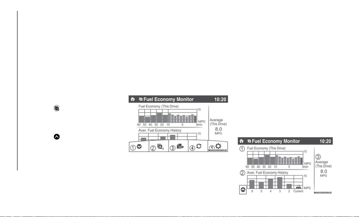
GETTING TO KNOW YOUR INSTRUMENT PANEL
90
FUEL ECONOMY MONITOR
— IF EQUIPPED
Description
The “Fuel Consumption” information is
displayed by operating each icon in the
display.
In addition, after completing a trip, the total
en
ergy efficiency to date is displayed in the
ending display when the ending display is
turned on.
Proceed as follows:
1. Select the
icon on the home screen to
display the applications screen.
2. Select the “Fuel Economy Monitor”.
3
. Select the
icon on the home screen to
display the applications screen.
NOTE:
When the menu is displayed by touching the
s
c
reen, the display is hidden automatically
after six seconds.
Select the icon in the menu and perform the
op
eration. Each icon operates as follows:
1. Hides the menu display.
2
. Displays the application screen.
3
. Resets the fuel economy data.
4
. Displays the following setting screen:
e
nding display on/off switching - On/off
switching for function which synchro
-
nizes reset fuel economy data to trip
me
ter (Trip A).
Fuel Economy Display Screen
Fuel Consumption Display
Information regarding fuel economy is
displayed:
1. Displays the fuel economy for the past
6
0 minutes:
Displays the fuel economy every
minute for the past 1 to 10 minutes.
Displays the fuel economy every
10 minutes for the past 10 to
60 minutes.
2. D
isplays the average fuel economy over
t
he past five resets and after the current
reset.
3. Calculates the average fuel economy
e
very minute after vehicle travel begins,
and displays it.
Average Fuel Economy Display Screen

91
NOTE:
The fuel economy data is synchronized
(l
inked) with the average fuel economy
displayed in the trip computer.
To reset the fuel economy data, press the
icon in the menu. (The average fuel
economy displayed in the trip computer
re
sets at the same time).
When the function, which synchronizes
the fuel economy monitor and the trip
meter, is on, reset Trip A of the trip meter.
Delete the average fuel economy informa-
tion displayed in the trip computer.
After resetting the fuel economy data, “-- -”
is
displayed while the average fuel economy
is calculated.
Ending Screen Display
If the ending display on the fuel economy
monitor is on when the ignition is cycled
from ON position to the OFF position, the
information regarding the fuel economy is
displayed.
WARNING LIGHTS AND
MESSAGES
Warning Lights And Messages
NOTE:
The warning light in the instrument panel
appears together with a dedicated
message and/or acoustic signal when
applicable. These indications are indica
-
tive and precautionary and as such must
no
t be considered as exhaustive and/or
alternative to the information contained in
the Owner’s Manual, which you are
advised to read carefully in all cases.
Always refer to the information in this
chapter in the event of a failure indication.
Failure indications displayed are divided
into two categories: serious and less
serious failures. Serious failures are indi
-
cated by a repeated and prolonged
wa
rning “cycle”. Less serious failures are
indicated by a warning “cycle” with a
shorter duration. The display cycle of both
categories can be interrupted. The instru
-
ment panel warning light will stay on until
th
e cause of the failure is eliminated.
Vehicles With Fiat Connect 7.0
The warning contents can be verified on the
au
dio system.
Proceed as follows:
1. I
f the warning light is turned on, select
icon on the home screen to display
the application screen.
2. S
elect “V
ehicle Status Monitor”
3. Select “W
arning Guidance” to display the
current warnings.
4. Select the applicable warning to view the
w
arning details.
For the following warning/indicator lights:
Master Warning Light
Brake System Warning Light
ABS Warning Light
Charging System Warning Light
Engine Oil Warning Light
Electric Throttle Warning Light
Cold Start Warning Light

GETTING TO KNOW YOUR INSTRUMENT PANEL
92
Check Engine Warning Light
Coolant Temperature Warning Light
Automatic Transmission Warning Light
Power Steering Malfunction Indicator
Light
Air Bag/Seat Belt Pretensioner System
Warning Light
Check Fuel Cap Warning Light
Low Fuel Warning Light
Seat Belt Warning Light
Door Ajar Warning Light
Low Washer Fluid Level Warning Light
Tire Pressure Monitoring System Warning
Light
KEY Warning Light
LED Headlight KEY Warning Light
BSM (Blind Spot Monitoring) OFF Indi-
cator Light
Traction Control System (TCS)/Dynamic
Stability Control (DSC) Indicator Light
DSC OFF Indicator Light
Security Indicator Light
Indicator Light
Passenger Air Bag Deactivation Warning
Light
The light turns on when the ignition is
sw
itched on for an operation check, and
turns off a few seconds later or when the
engine is started. If the light does not turn on
or remains turned on, have the vehicle
inspected at an authorized dealer.
NOTE:
Only for “Brake System Warning Light:” the
li
ght turns on continuously when the parking
brake is applied.

93
Red Warning Lights
Warning Light What It Means
Parking Brake Warning - Warning Light Inspection/Low Brake Fluid Level Warning
Parking Brake Warning / Warning Light Inspection
The light illuminates when the parking brake is applied with the ignition switched to START or ON. It turns off when the
p
a
rking brake is fully released.
Low Brake Fluid Level Warning
If the brake warning light remains illuminated even though the parking brake is released, the brake fluid may be low or
th
ere could be a problem with the brake system. Park the vehicle in a safe place immediately and contact an authorized
dealer.
NOTE:
Do not drive with the brake system warning light illuminated. Contact an authorized dealer to have the brakes inspected
as soon as possible. Driving with the brake system warning light illuminated is dangerous. It indicates that your brakes
may not work at all or that they could completely fail at any time. If this light remains illuminated, after checking that
the parking brake is fully released, have the brakes inspected immediately.
The effectiveness of the braking may diminish so you may need to push the brake pedal more strongly than normal to
stop the vehicle.
Stop the vehicle in a safe place immediately and contact an authorized dealer.

GETTING TO KNOW YOUR INSTRUMENT PANEL
94
Electronic Brake-Force Distribution (EBD) System Warning
If the EBD (Electronic Brake-force Distribution) control unit determines that some components are operating incorrectly,
th
e control unit may illuminate the brake system warning light and the Anti Lock Brake System (ABS) warning light
simultaneously. The problem is likely to be the electronic brake force distribution system. Stop the vehicle in a safe place
immediately and contact an authorized dealer.
NOTE:
Do not drive with both the ABS warning light and brake warning light illuminated. Contact an authorized dealer to have
the brakes inspected as soon as possible. Driving when the brake system warning light and ABS warning light are illumi-
nated simultaneously is dangerous.
When both lights are illuminated, the rear wheels could lock more quickly in an emergency stop than under normal
circumstances.
Alternator Failure
If the warning light illuminates while driving, it indicates a malfunction of the alternator or of the charging system. Drive
to
the side of the road and park off the right-of-way. Stop the vehicle in a safe place immediately and contact an
authorized dealer.
NOTE:
Do not continue driving when the charging system warning light is illuminated because the engine could stop unexpectedly.
Warning Light What It Means
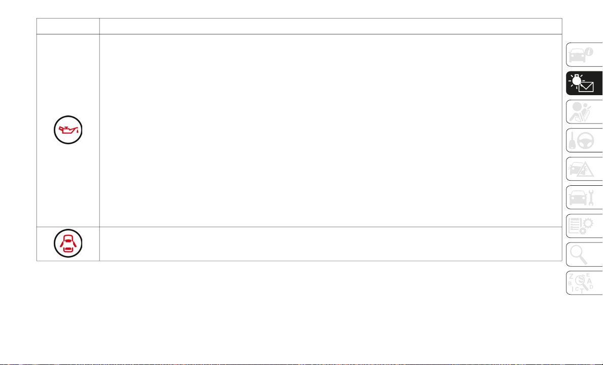
95
Low Engine Oil Pressure
This warning light indicates low engine oil pressure.
NOTE:
Do not run the engine if the oil pressure is low. Otherwise, it could result in extensive engine damage.
If the light illuminates or the warning indication is displayed while driving:
1. D
rive to the side of the road and park off the right-of-way on level ground.
2
. Turn off the engine and wait five minutes for the oil to drain back into the sump.
3
. Inspect the engine oil level. If it's low, add the appropriate amount of engine oil while being careful not to overfill.
4
. Start the engine and check the warning light.
N
OTE:
Do not run the engine if the oil level is low. Otherwise, it could result in extensive engine damage.
If the light remains illuminated even though the oil level is normal or after adding oil, stop the engine immediately and
c
o
ntact an authorized dealer.
Door-Open Warning Light
The light turns on if any door is not closed securely.
Close the door securely.
Warning Light What It Means
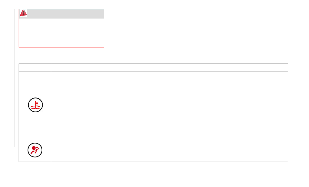
GETTING TO KNOW YOUR INSTRUMENT PANEL
96
Red Warning Lights
WARNING!
Driving a vehicle with the red brake light
on is dangerous. Part of the brake system
may have failed. It will take longer to stop
the vehicle. You could have a collision.
Have the vehicle checked immediately.
Warning Light What It Means
High Engine Coolant Temperature Warning Light
The light flashes when the engine coolant temperature is extremely high, and illuminates when the engine coolant
t
e
mperature increases further.
Handling Procedure
Flashing Light: drive slowly to reduce engine load until you can find a safe place to stop the vehicle and wait for the engine
to cool down.
Illuminated Light: this indicates the possibility of overheating. Park the vehicle in a safe place immediately and stop the
engine. Refer to “If Your Engine Overheats” in “In Case Of Emergency” for further information.
NOTE:
Do not drive the vehicle with the high engine coolant temperature warning light illuminated. Otherwise, it could result in
d
a
mage to the engine. Contact an authorized dealer.
Air Bag/Seat Belt Pretensioner System Warning
A system malfunction is indicated if the warning light constantly flashes, constantly illuminates or does not illuminate at
al
l when the ignition is placed in the ON position. If any of these occur, contact an authorized dealer as soon as possible.
The system may not operate in an accident.
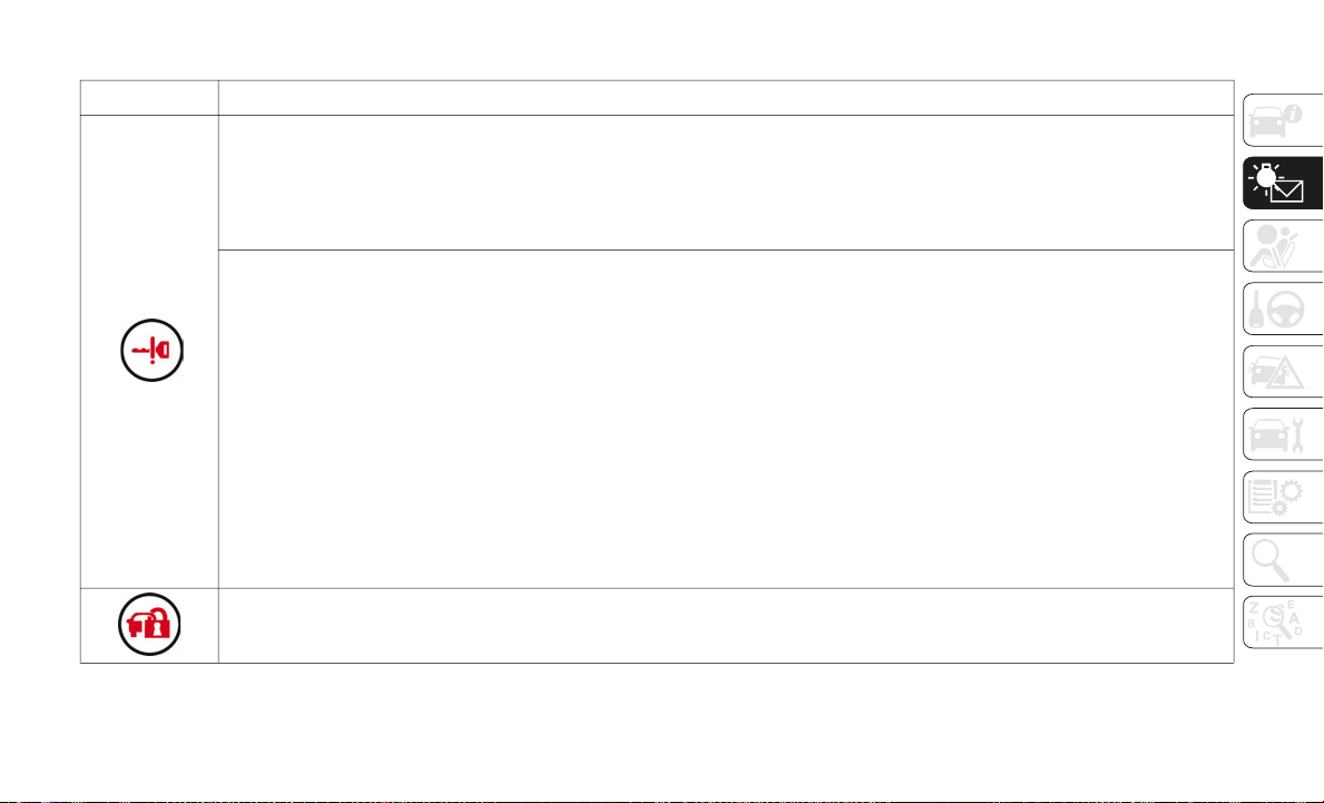
97
Red Warning Lights
Warning Light What It Means
Key Warning Light — Illuminated
If any malfunction occurs in the keyless entry system, it illuminates continuously.
NOTE:
If the key warning indicator light illuminates or the push button start indicator light (amber) flashes, the engine may not
s
t
art. Contact an authorized dealer as soon as possible.
Key Warning Light — Flashing
Advanced Key Fob Malfunction
Take the appropriate action and verify that the warning light turns off.
The advanced key fob battery is discharged: replace the key fob battery.
The advanced key fob is not within the operation range/is placed in areas inside the cabin where it is difficult for the key to be
detected: bring the advanced key fob into the operation range.
A key fob from another manufacturer similar to the advanced key fob is in the operation range: take the key fob from another
manufacturer similar to the advanced key out of the operation range.
Without the ignition switched OFF, the advanced key is taken out of the vehicle, and then all the doors are closed: bring the
advanced key fob back into the vehicle.
If the engine cannot be started, try starting it using the emergency operation for starting the engine, and contact an
au
thorized dealer.
Vehicle Security Alarm System
The warning light switches on to report a failure of the vehicle security alarm system. Contact an authorized dealer as soon
as
possible.

GETTING TO KNOW YOUR INSTRUMENT PANEL
98
Amber Warning Lights
Warning Light What It Means
ABS Warning Light
If the ABS warning light stays on while you're driving, when the ABS control unit has detected a system malfunction. If
t
h
is occurs, your brakes will function normally as if the vehicle had no ABS. Should this happen contact an authorized
dealer as soon as possible.
NOTE:
When the engine is jump-started to charge the battery, uneven RPM occurs and the ABS warning light may illuminate.
If this occurs, it is the result of the weak battery and does not indicate an ABS malfunction. Recharge the battery.
The brake assist system does not operate while the ABS warning light is illuminated.
Malfunction Indicator Light
If this light illuminates while driving, the vehicle may have a problem. It is important to note the driving conditions when
th
e light illuminated and contact an authorized dealer.
The malfunction indicator light may illuminate in the following cases:
The engine's electrical system has a problem.
The emission control system has a problem.
The fuel tank level is very low or approaching empty.
The fuel-filler cap is missing or not tightened securely.
If the malfunction indicator light remains on, or it flashes continuously, do not drive at high speeds and contact an
au
thorized dealer as soon as possible.
99
WARNING!
A malfunctioning catalytic converter, as
referenced above, can reach higher
temperatures than in normal operating
conditions. This can cause a fire if you
drive slowly or park over flammable
substances such as dry plants, wood,
cardboard, etc. This could result in death
or serious injury to the driver, occupants or
others.
CAUTION!
Prolonged driving with the Malfunction
Indicator Light (MIL) on could cause
damage to the engine control system. It
also could affect fuel economy and
driveability. If the MIL is flashing, severe
catalytic converter damage and power loss
will soon occur. Immediate service is
required.

GETTING TO KNOW YOUR INSTRUMENT PANEL
100
Amber Warning Lights
Warning Light What It Means
Tire Pressure Monitoring System (TPMS) Warning Light — If Equipped
The warning light switches on and a message is displayed to indicate that the tire pressure is lower than the recommended
va
lue and/or that slow pressure loss is occurring. In these cases, optimal tire duration and fuel consumption may not be
guaranteed.
Should one or more tires be in the condition mentioned above, the display will show the indications corresponding to each tire
in
sequence.
NOTE:
Do not continue driving with one or more flat tires as handling may be compromised. Stop the vehicle, avoiding sharp braking
an
d steering. Repair immediately using the dedicated tire repair kit and contact an authorized dealer as soon as possible.
Each tire, including the spare (if provided), should be checked monthly when cold and inflated to the inflation pressure
re
commended by the vehicle manufacturer on the vehicle placard or tire inflation pressure label. If your vehicle has tires of a
different size than the size indicated on the vehicle placard or tire inflation pressure label, you should determine the proper
tire inflation pressure for those tires.
As an added safety feature, your vehicle has been equipped with a Tire Pressure Monitoring System (TPMS) that illuminates a
lo
w tire pressure telltale when one or more of your tires is significantly under-inflated. Accordingly, when the low tire pressure
telltale illuminates, you should stop and check your tires as soon as possible, and inflate them to the proper pressure. Driving
on a significantly under-inflated tire causes the tire to overheat and can lead to tire failure. Under-inflation also reduces fuel
efficiency and tire tread life, and may affect the vehicle’s handling and stopping ability.
Please note that the TPMS is not a substitute for proper tire maintenance, and it is the driver’s responsibility to maintain
co
rrect tire pressure, even if under-inflation has not reached the level to trigger illumination of the TPMS low tire pressure
telltale.
The TPMS malfunction indicator is combined with the low tire pressure telltale. When the system detects a malfunction,
the telltale will flash for approximately one minute and then remain continuously illuminated. This sequence will continue
upon subsequent vehicle start-ups as long as the malfunction exists. When the malfunction indicator is illuminated, the
system may not be able to detect or signal low tire pressure as intended. TPMS malfunctions may occur for a variety of
reasons, including the installation of replacement or alternate tires or wheels on the vehicle that prevent the TPMS from
functioning properly. Always check the TPMS malfunction telltale after replacing one or more tires or wheels on your
vehicle to ensure that the replacement or alternate tires and wheels allow the TPMS to continue to function properly.

101
CAUTION!
The TPMS has been optimized for the
original equipment tires and wheels.
TPMS pressures and warning have been
established for the tire size equipped on
your vehicle. Undesirable system operation
or sensor damage may result when using
replacement equipment that is not of the
same size, type, and/or style. Aftermarket
wheels can cause sensor damage. Using
aftermarket tire sealants may cause the
Tire Pressure Monitoring System (TPMS)
sensor to become inoperable. After using
an aftermarket tire sealant it is
recommended that you take your vehicle to
an authorized dealer to have your sensor
function checked.

GETTING TO KNOW YOUR INSTRUMENT PANEL
102
Amber Warning Lights
Amber Warning Lights
Warning Light What It Means
Power Steering Malfunction Indicator Light
The light illuminates if the electric power steering has a malfunction. If the light illuminates, stop the vehicle in a safe
p
l
ace and do not operate the steering wheel. There is no problem if the light turns off after a while. Contact an authorized
dealer if the light illuminates continuously.
NOTE:
If the indicator light illuminates, the power steering will not operate normally. If this happens, the steering wheel can
still be operated, however, the operation may feel heavy compared to normal, or the steering wheel could vibrate when
turning.
Repeatedly jerking the steering wheel left and right while the vehicle is stopped or moving extremely slowly will cause
the power steering system to go into protective mode which will make the steering feel heavy, but this does not indicate
a problem. If this occurs, park the vehicle safely and wait several minutes for the system to return to normal.
Warning Light What It Means
Automatic Transmission Warning Light — If Equipped
The light illuminates when the transmission has a problem.
NOTE:
If the automatic transmission warning light illuminates, the transmission has an electrical problem. Continuing to drive your
v
e
hicle in this condition could cause damage to your transmission. Contact an authorized dealer as soon as possible.
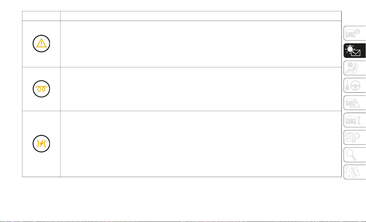
103
Master Warning Light
Vehicles Equipped With Fiat Connect 3.0 System
The warning light turns on continuously if there is a malfunction in the battery management system or there is a
m
a
lfunction in the brake switch. Contact an authorized dealer as soon as possible.
Vehicles Equipped With Fiat Connect 7.0 System
The warning light turns on when the system has a malfunction. Operate the center display and verify the content.
Contact an authorized dealer as soon as possible.
Cold Start Disable Indicator Light
When the ambient temperature is extremely low, the engine may not crank even when the engine starting procedure is
pe
rformed. At this time, the Cold Start Disable Indicator light in the instrument cluster flashes. However, this does not
indicate a problem.
NOTE:
Place your vehicle in a warm garage until the temperature has risen to a sufficient level to enable engine starting.
Electric Throttle Control Warning Light
This light informs you of a problem with the Electronic Throttle Control (ETC) system. If a problem is detected while the
en
gine is running, the light will either stay on or flash depending on the nature of the problem. Cycle the ignition key when
the vehicle is safely and completely stopped and the transmission is placed in the PARK position. The light should turn
off. If the light remains on with the engine running, your vehicle will usually be drivable; however, see an authorized dealer
for service as soon as possible.
If the light continues to flash when the engine is running, immediate service is required and you may experience reduced
pe
rformance, an elevated/rough idle, or engine stall and your vehicle may require towing. The light will come on when the
ignition is first turned to ON/RUN and remain on briefly as a bulb check. If the light does not come on during starting,
have the system checked by an authorized dealer.
Warning Light What It Means

GETTING TO KNOW YOUR INSTRUMENT PANEL
104
Amber Warning Lights
Warning
Lights
What It Means
LED Headlight Warning Light
This light illuminates if there is a malfunction in the LED headlight. Contact an authorized dealer as soon as possible.
Blind Spot Monitoring (BSM) Off Indicator Light — If Equipped
A problem in the system may be indicated under the following conditions:
The light does not turn on when the ignition is placed in the ON position.
The light remains turned on even if the Blind Spot Monitoring (BSM) switch is operated.
It turns on while driving the vehicle.
Contact an authorized dealer as soon as possible.
If the vehicle is driven on a road with less traffic and few vehicles that the radar sensors can detect, the system may pause
(t
he warning light illuminates). However, it does not indicate a malfunction.
Low Fuel Warning Light
The light turns on when the remaining fuel is about 2.3 gallons (9.0 liters).
The light illumination timing may vary because fuel inside the fuel tank moves around according to the driving conditions
an
d the vehicle posture. Add fuel.
Low Washer Fluid Level Warning Light — If Equipped
This warning light indicates that little washer fluid remains. Add washer fluid.
Cruise Control Activation — If Equipped
The warning light illuminates when the cruise control system is activated.
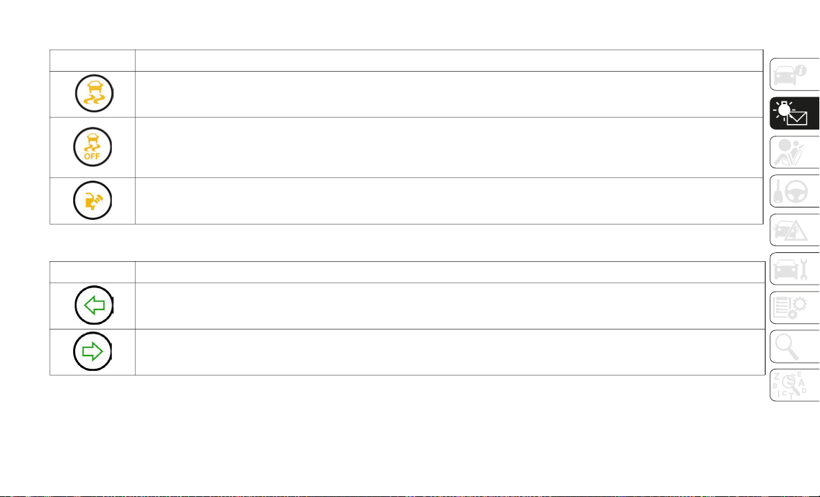
105
Amber Warning Lights
Green Warning Lights
Warning Light What It Means
TCS / DSC System Indicator Light
The warning light turns on when the TCS/DSC system is active. This means that the vehicle is in critical stability and grip
c
o
nditions.
DSC Off Indicator Light
This indicator light stays on for a few seconds when the ignition is switched ON. It also illuminates when the DSC OFF
sw
itch is pressed and TCS/DSC is switched off. For further information regarding the DSC OFF Switch, refer to “Safety
Systems” in “Safety”.
Loose Fuel Filler Cap Indicator Light
If the check fuel filler cap warning light illuminates while driving, the fuel filler cap may not be installed properly. Stop
th
e engine and reinstall the fuel filler cap.
Warning Light What It Means
Left Direction Indicator
The warning light turns on when the direction indicator control lever is moved downwards or, together with the right
d
i
rection indicator, when the hazard warning light button is pushed.
Right Direction Indicator
The warning light turns on when the direction indicator control lever is moved upwards or, together with the left direction
in
dicator, when the hazard warning light button is pushed.

GETTING TO KNOW YOUR INSTRUMENT PANEL
106
Parking Lights And Normal Beam Headlights
The warning light turns on when parking lights or normal beam headlights are turned on.
Cruise Control — If Equipped
The warning light turns on when a cruising speed has been set.
Key Indicator Light
The warning light turns on when the engine is ready to start.
Warning Light Flashing
When the keyless START/STOP button is pushed from ON to ACC or OFF position, the warning light may flash for
a
p
proximately 30 seconds indicating that the remaining battery power of the key is low. Replace with a new battery before
the key becomes unusable.
Blue Warning Light
Warning Light What It Means
High Beam Headlights
The warning light switches on when the high beam headlights are turned on.
Low Engine Coolant Temperature Indicator Light
The light illuminates continuously when the engine coolant temperature is low and turns off after the engine is warm.
If the low engine coolant temperature indicator light remains illuminated after the engine has been sufficiently warmed
u
p
, the temperature sensor could have a malfunction. Contact an authorized dealer.
Warning Light What It Means
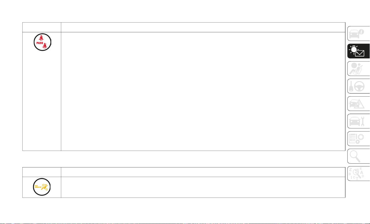
107
Warning Light (Red Color) On Dashboard Trim
Warning Light What It Means
Seat Belt Warning Light
The seat belt warning light turns on if the driver or passengers seat is occupied and the seat belt is not fastened with the
i
g
nition placed in the ON position.
If the driver or passengers seat belt is unfastened (only when the passenger seat is occupied) and the vehicle is driven at
a
speed faster than about 12 mph (20 km/h), the warning light flashes. After a short time, the LED stops flashing, but
re
mains illuminated.
If a seat belt remains unfastened, the LED flashes again for a given period of time.
If the driver or passengers seat belt is unfastened after the LED turns on, and the vehicle speed exceeds 12 mph (20 km/h),
th
e LED flashes again.
With Passenger Occupant Classification System:
to allow the passenger occupant classification sensor to function properly,
do not place and sit on an additional seat cushion on the passengers seat. The sensor may not function properly because
the additional seat cushion could cause sensor interference.
Without Passenger Occupant Classification System:
placing heavy items on the passengers seat may cause the passengers
seat belt warning function to operate depending on the weight of the item. To allow the passengers seat weight sensor to
function properly, do not place and sit on an additional seat cushion on the passengers seat. The sensor may not function
properly because the additional seat cushion could cause sensor interference. If a small child is seated on the passengers
seat, the warning light may not operate.
Fasten the seat belts.
Warning Light (Amber Color) On Instrument Cluster Trim
Warning Light What It Means
Passenger Air Bag Deactivation Indicator Light
The light turns on when the ignition is switched on for an operation check, and turns off a few seconds later or when the
en
gine is started. If the light does not turn on or remains turned on, contact an authorized dealer.

GETTING TO KNOW YOUR INSTRUMENT PANEL
108
Message Indicated On Display — If
Equipped With Fiat Connect 7.0 System
Message Indicated On Display
If a message is displayed in the center
display, take appropriate action (in a calm
manner) according to the displayed
message.
If the following messages are displayed in
th
e center display, a vehicle system may be
malfunctioning:
Engine Coolant Temperature High: displays
if the engine coolant temperature has
increased excessively.
Charging System Malfunction: displays if
the charging system has a malfunction.
Temperature Warning: the following
message is displayed when the tempera-
ture around the center display is high.
L
o
wering the temperature of the inside of
the vehicle or the temperature around the
center display by avoiding direct sunlight
is recommended.
Stop the vehicle in a safe place and contact
an
authorized dealer.
Warning Sound Is Activated
Lights-On Reminder
If lights are on and the ignition is placed in
th
e ACC position, or the ignition is placed in
the OFF position, a continuous beep sound
will be heard when the driver's door is
opened.
NOTE:
When the ignition is placed in the ACC
position, the “Ignition Not Cycled Off
Warning Beep” overrides the lights-on
reminder.
A personalized function is available to
change the sound volume for the lights-on
reminder.
Air Bag/Seat Belt Pretensioner System Warning
Be
ep
If there is a problem with the air bag/seat
be
lt pretensioner systems and the warning
light illumination, a warning beep sound will
be heard for about five seconds every
minute.
The air bag and seat belt pretensioner
sy
stem warning beep sound will continue to
be heard for approximately 35
minutes.
Co
ntact an authorized dealer as soon as
possible.
Seat Belt Warning Beep
Except Mexico
If the driver's seat belt is not fastened when
th
e ignition is in the ON position, a beep
sound will be heard for about six seconds.
If the driver or the passengers seat belt is not
fa
stened and the vehicle is driven at a speed
faster than about 12
mph (20 km/h), a beep
so
und will be heard again for a specified
period of time.
CAUTION!
Do not drive the vehicle with the air bag/
seat belt pretensioner system warning
beep sounding. Driving the vehicle with
the air bag/seat belt pretensioner system
warning beep sounding is dangerous. In a
collision, the air bags and the seat belt
pretensioner system will not deploy and
this could result in death or serious injury.
Contact an authorized dealer as soon as
possible.
109
Until a seat belt is fastened or a given period
of time has elapsed, the beep sound will not
stop even if the vehicle speed falls below
12
mph (20 km/h).
NOTE:
To allow the passenger occupant classifi-
cation sensor to function properly, do not
pl
ace and sit on an additional seat cushion
on the passengers seat. The sensor may
not function properly because the addi
-
tional seat cushion could cause sensor
in
terference.
If a small child is seated on the passen-
gers seat, the warning beep may not
op
erate.
Mexico
If the vehicle speed exceeds about 12 mph
(
2
0 km/h) with the driver or passengers seat
be
lt unfastened, a warning beep sounds
continuously. If the seat belt remains unfas
-
tened, the beep sound stops once and then
co
ntinues for about 90 seconds. The beep
stops after the driver or passengers seat belt
is fastened.
Until a seat belt is fastened or a given period
of
time has elapsed, the beep sound will not
stop even if the vehicle speed falls below
12
mph (20 km/h).
Ignition Not Switched OFF
If the driver's door is opened while the igni-
tion is placed in the ACC position, a contin-
uous beep sound will be heard to notify the
dr
iver that the ignition has not been placed
in the OFF position.
Left in this condition, the keyless entry
sy
stem will not operate, the car cannot be
locked, and the battery power will be
depleted.
Key Removed From Vehicle Warning Beep
Vehicles With Advanced Keyless Function
If the key is taken out of the vehicle while the
ig
nition is not switched OFF and all the doors
are closed, the beep which sounds outside of
the vehicle will be heard six times, and the
beep which sounds inside the vehicle will be
heard six times, and the KEY warning light
(red)
will flash continuously in the instru-
ment cluster to notify the driver that the igni-
tion has not been switched OFF.
Vehicles Without Advanced Keyless Function
If the key is taken out of the vehicle while the
i
g
nition is not switched OFF and all the doors
are closed, a beep will be heard inside the
vehicle 6 times and the KEY warning light
(red)
will turn on continuously in the
instrument cluster to notify the driver that
th
e ignition has not been switched OFF.
WARNING!
Placing heavy items on the front
passenger seat may cause the front
passenger seat belt warning function to
operate depending on the weight of the
item.
To allow the front passenger seat weight
sensor to function properly, do not place
and sit on an additional seat cushion on
the front passenger seat. The sensor may
not function properly because the addi
-
tional seat cushion could cause sensor
in
terference.
When a small child sits on the front
passenger seat, it is possible that the
warning beep will not operate.

GETTING TO KNOW YOUR INSTRUMENT PANEL
110
NOTE:
Because the key fob uses low-intensity radio
wa
ves, the warning may activate if the key
fob is carried together with a metal object or
i
t
is placed in a poor signal reception area.
Request Switch Inoperable Warning Beep — If
Eq
uipped With Advanced Keyless Function
If the request switch on the exterior door
ha
ndle is pushed with a door open, or the
ignition has not been placed in the OFF posi
-
tion, a beep will be heard for about two
se
conds to indicate that the doors, and trunk
lid cannot be locked.
Key Left-In-Trunk Compartment Warning Beep
—
If Equipped With Advanced Keyless Function
If the key fob is left in the trunk with all doors
lo
cked and the trunk lid closed, a beep
sound is heard for about 10 seconds to
remind the driver the key fob has been left in
the trunk.
If this happens, open the trunk lid by
pu
shing the electric trunk lid opener and
remove the key fob.
A key fob removed from the trunk may not
fu
nction because its functions may have
been temporarily suspended. To restore the
key fob function, perform the applicable
procedure. See paragraph “Keys” in “Getting
To Know Your Vehicle” chapter.
Key Left-In-Vehicle Warning Beep
(with the advanced keyless function)
If a key fob is left in the vehicle and all the
do
ors and the trunk are locked using a sepa-
rate key fob, a beep sound is heard for about
1
0
seconds to remind the driver that the key
fob has been left in the vehicle.
If this happens, open the door and remove
th
e key fob. A key fob removed from the
vehicle this way may not function because its
functions may have been temporarily
suspended.
Perform the applicable procedure to restore
th
e functions of the key fob. See paragraph
“Keys” in “Getting To Know Your Vehicle”
chapter.
Vehicle Speed Alarm — If Equipped
The vehicle speed alarm function is designed
to
alarm the driver via a single beep sound
and a warning indication in the instrument
cluster that the previously set vehicle speed
has been exceeded.
You can change the vehicle speed setting at
wh
ich the warning is triggered. See para-
graph “Trip Computer” in “Getting To Know
Y
o
ur Vehicle” chapter.
Tire Inflation Pressure Warning Beep — If
Eq
uipped
Vehicle With Conventional Tires:
the warning
beep sound will be heard for about three
seconds when there is any abnormality in tire
inflation pressures. See “TPMS” in “Safety”
chapter.
Vehicle With Run-Flat Tires (
If Equipped): the
warning beep sound will be heard for about
three seconds if the tire pressures decrease.
If the tire pressure decreases extremely, a
beep sound will be heard for approximately
30 seconds. See “TPMS” in “Safety”
chapter.
Blind Spot Monitoring (BSM) System Warning
Be
ep — If Equipped
Driving Forward:
the warning beep operates
when the direction indicator lever is operated
to the side where the Blind Spot Monitoring
(BSM) warning light is illuminated.

111
NOTE:
A personalized function is available to
ch
ange the Blind Spot Monitoring (BSM)
warning beep sound volume.
Reversing: if a moving object such as a
v
ehicle or two-wheeled vehicle approaches
on the left or right from behind your vehicle,
the Blind Spot Monitoring (BSM) warning
sound is activated.
Electronic Steering Lock Warning Beep
The warning beep operates if the steering
w
h
eel is not unlocked after the keyless igni-
tion START/STOP button is pushed.
Speed Limiter Warning Beep — If Equipped
If the vehicle speed exceeds the set speed by
a
b
out 2 mph (3 km/h) or more, a warning
be
ep operates continuously.
The warning beep operates until the vehicle
sp
eed decreases to the set speed or less.
PERSONALIZATION
FEATURES
Overview
The following Personalization Features can
be set or changed by the customer or by an
authorized dealer.
Personalization Features differ depending on
th
e market and specification.
Settings change method
1. S
ettings can be changed by operating the
c
enter display screen
A: Refer to the “Display Settings” in
“Operating Tips For iPod” in the Fiat
Connect 7.0 Supplement for further
information.
B: Refer to “Fuel Economy Monitor”
paragraph in this chapter.
2. Settings can be changed by operating the
v
ehicle switches
C: Refer to “Auto Lock/Unlock Func-
tion” paragraph in “Getting To Know
Yo
ur Vehicle” for further information.
D: Refer to “Key Fob” in “Getting To
Know Your Vehicle” for further infor-
mation.
E: Refer to “Doors” in “Getting To
Know Your Vehicle” for further infor-
mation.
3. S
ettings can be changed by an authorized
d
ealer (refer to the following table)
X: Refer to an authorized dealer for
setting change.

GETTING TO KNOW YOUR INSTRUMENT PANEL
112
Item Feature Factory Setting Available Settings
Settings Change Method
1 2 3
Safety
Blind Spot Monitoring
Sy
stem (if equipped)
Warning Beep Volume
(*)
High High/Low/Off A — X
Vehicle
Door Locks
Operation condition of
au
to lock/unlock
function
Lock: When Driving/
Un
lock: IGN Off
Lock: When Driving/
Un
lock: In Park/Lock:
Out of Park Unlock: In
Park/Lock: Shifting Out
of Park/ Lock: When
Driving Unlock: IGN Off/
Lock: When Driving/Off
A C X
Keyless Entry System
Time for locking door
au
tomatically
30 seconds
90 seconds/60 seconds/
30 seconds
A — X
Advanced Keyless Entry
S
y
stem
Time for locking door
au
tomatically
30 seconds
90 seconds/60 seconds/
30 seconds
A — X
Auto-lock function
op
eration/non
operational
Off On/Off A — X
Beep volume when
lo
cking/unlocking
Off or Medium High/Medium/Low/Off A D/E X

113
Illuminated Entry
System
Time until interior lights
tu
rn off after closing
door
15 seconds
60 seconds/30 seconds/
1
5
seconds/7.5 seconds
A — X
Time until interior lights
tu
rn off automatically
when any door is not
closed completely
30 minutes
60 minutes/30 minutes/
10 minutes
A — X
Auto-Wiper Control
Operational/
n
o
n-operational
On On/Off (**) A — X
Daytime Running Lights
(D
RL)
Operational/
non-operational
On On/Off — — X
Auto headlight off (***)
Time until headlights
tu
rn off
30 second
120 seconds/90
se
conds/60 seconds/
30 seconds/
Off (****)
A — X
Auto-Light Control
Timing by which lights
tu
rn on
Medium
High/Med. High/
Medium/Med. Low/Low
A — X
Adaptive Front Lighting
Sy
stem (AFS)
Operational/
non-operational (***)
On On/Off A — X
Lights-On Reminder
Warning beep volume High High/Low/Off A — X
Coming Home System
Time until headlights
t
u
rn off
30 seconds
120 seconds/90
s
e
conds/60 seconds/
}30 seconds/Off
A — X
Item Feature Factory Setting Available Settings
Settings Change Method
1 2 3

GETTING TO KNOW YOUR INSTRUMENT PANEL
114
(—) Feature setting change not available.
(*) Only the volume of the warning beep during Blind Spot Monitoring (BSM) operation can be changed. The volume of the warning beep during Rear
Cross Traffic Alert (RCTA) operation cannot be changed.
(**) If the auto-wiper control is set to Off, the wiper lever AU
TO position is set to intermittent operation.
(***) Though these systems can be turned Off, doing so will defeat the purpose of the system and FCA recommends that these systems remain On.
(****) Available only in display from the center display.
Leaving Home Light
System
Operational/
Non-operational
On or Off On/Off A — X
Turn Signals Beep volume Low High/Low A — X
Three-Flash Turn Signal
Operational/
No
n-operational
On or Off On/Off A — X
System
Language
Language indicated in
di
splay
English
Depends on
market (****)
A — X
Temperature
Temperature unit
in
dicated in display
°C °F/°C A — X
Distance
Distance unit indicated
in
display
mi or km mi/km A — X
Fuel Economy Monitor
Ending Display On/Off Off On/Off B — X
Fuel Economy Resetting
Pr
ocedure
Linkage/non-linkage
wi
th fuel economy reset
and trip meter reset
Off On/Off B — X
Item Feature Factory Setting Available Settings
Settings Change Method
1 2 3
115
(Continued)
(Continued)
ONBOARD DIAGNOSTIC
SYSTEM — OBD II
Your vehicle is equipped with a sophisticated
Onboard Diagnostic system called OBD II.
This system monitors the performance of the
emissions, engine, and automatic transmis
-
sion control systems. When these systems
ar
e operating properly, your vehicle will
provide excellent performance and fuel
economy, as well as engine emissions well
within current government regulations.
If any of these systems require service, the
OB
D II system will turn on the Malfunction
Indicator Light (MIL). It will also store diag
-
nostic codes and other information to assist
yo
ur service technician in making repairs.
Although your vehicle will usually be drivable
and not need towing, see an authorized
dealer for service as soon as possible.
Onboard Diagnostic System (OBD II)
Cybersecurity
Your vehicle is required to have an Onboard
Diagnostic system (OBD II) and a connection
port to allow access to information related to
the performance of your emissions controls.
Authorized service technicians may need to
access this information to assist with the
diagnosis and service of your vehicle and
emissions system.
For further information, refer to “CyberSecu-
rity” in “Tips, Controls, and General Informa-
tion” in your Owner’s Manual Radio
Su
pplement.
EMISSIONS INSPECTION
AND MAINTENANCE
PROGRAMS
In some localities, it may be a legal require-
ment to pass an inspection of your vehicle's
em
issions control system. Failure to pass
could prevent vehicle registration.
CAUTION!
Prolonged driving with the MIL on could
cause further damage to the emission
control system. It could also affect fuel
economy and driveability. The vehicle
must be serviced before any emissions
tests can be performed.
If the MIL is flashing while the vehicle is
running, severe catalytic converter
damage and power loss will soon occur.
Immediate service is required.
WARNING!
ONLY an authorized service technician
should connect equipment to the OBD II
connection port in order to read the VIN,
diagnose, or service your vehicle.
If unauthorized equipment is connected
to the OBD II connection port, such as a
driver-behavior tracking device, it may:
CAUTION! (Continued)
Be possible that vehicle systems,
including safety related systems,
could be impaired or a loss of vehicle
control could occur that may result in
an accident involving serious injury
or death.
Access, or allow others to access,
information stored in your vehicle
systems, including personal informa
-
tion.
WARNING! (Continued)

GETTING TO KNOW YOUR INSTRUMENT PANEL
116
For states that require an Inspec-
tion and Maintenance (I/M), this
ch
eck verifies the “Malfunction
Indicator Light (MIL)” is func
-
tioning and is not on when the engine is
ru
nning, and that the OBD II system is ready
for testing.
Normally, the OBD II system will be ready.
Th
e OBD II system may not be ready if your
vehicle was recently serviced, recently had a
depleted battery or a battery replacement. If
the OBD II system should be determined not
ready for the I/M test, your vehicle may fail
the test.
Your vehicle has a simple ignition actuated
te
st, which you can use prior to going to the
test station. To check if your vehicle's OBD II
system is ready, you must do the following:
1. Cycle the ignition switch to the ON posi-
t
ion, but do not crank or start the engine.
NOTE:
If you crank or start the engine, you will have
t
o
start this test over.
2. As soon as you cycle the ignition switch
t
o the ON position, you will see the
“Malfunction Indicator Light (MIL)”
symbol come on as part of a normal bulb
check.
3. Approximately 15 seconds later, one of
t
wo things will happen:
The MIL will flash for about 10
seconds and then return to being fully
illuminated until you turn OFF the
ignition or start the engine. This
means that your vehicle's OBD II
system is not ready and you should not
proceed to the I/M station.
The MIL will not flash at all and will
remain fully illuminated until you
place the ignition in the off position or
start the engine. This means that your
vehicle's OBD II system is ready and
you can proceed to the I/M station.
If your OBD II system is no
t ready, you should
see an authorized dealer or repair facility. If
your vehicle was recently serviced or had a
battery failure or replacement, you may need
to do nothing more than drive your vehicle as
you normally would in order for your OBD II
system to update. A recheck with the above
test routine may then indicate that the
system is now ready.
Regardless of whether your vehicle's OBD II
sy
stem is ready or not, if the MIL is illumi-
nated during normal vehicle operation you
s
h
ould have your vehicle serviced before
going to the I/M station. The I/M station can
fail your vehicle because the MIL is on with
the engine running.
117
(Continued)
SAFETY SYSTEMS
The vehicle has the following safety systems:
Anti-Lock Braking System (ABS)
Traction Control System (TCS)
Dynamic Stability Control (DSC)
For the operation of the systems, see the
fol
lowing pages.
Anti-Lock Braking System (ABS)
The Anti-Lock Braking System (ABS) control
unit continuously monitors the speed of each
wheel. If one wheel is about to lock up, the
ABS responds by automatically releasing and
reapplying that wheel's brake. The driver will
feel a slight vibration in the brake pedal and
may hear a chattering noise from the brake
system. This is normal ABS system opera
-
tion. Continue to depress the brake pedal
wit
hout pumping the brakes. The warning
light turns on when the system has a
malfunction. Refer to “Warning Lights And
Messages” in “Getting To Know Your Instru
-
ment Panel” for further information.
NOTE:
Braking distances may be longer on loose
surfaces (snow or gravel, for example)
which usually have a hard foundation. A
vehicle with a normal braking system may
require less distance to stop under these
conditions because the tires will build up
a wedge of surface layer when the wheels
skid.
The sound of the ABS operating may be
heard when starting the engine or immedi-
ately after starting the vehicle; however, it
d
oe
s not indicate a malfunction.
WARNING!
The ABS contains sophisticated elec-
tronic equipment that may be suscep-
tible to interference caused by
i
mp
roperly installed or high output radio
transmitting equipment. This interfer
-
ence can cause possible loss of anti-lock
bra
king capability. Installation of such
equipment should be performed by qual
-
ified professionals.
Pumping of the Anti-Lock Brakes will
diminish their effectiveness and may
lead to a collision. Pumping makes the
stopping distance longer. Just press
firmly on your brake pedal when you
need to slow down or stop.
The ABS cannot prevent the natural laws
of physics from acting on the vehicle, nor
can it increase braking or steering effi
-
ciency beyond that afforded by the
con
dition of the vehicle brakes and tires
or the traction afforded.
The ABS cannot prevent collisions,
including those resulting from excessive
speed in turns, following another vehicle
too closely, or hydroplaning.
The capabilities of an ABS equipped
vehicle must never be exploited in a
reckless or dangerous manner that could
jeopardize the user’s safety or the safety
of others.
WARNING! (Continued)

SAFETY
118
Traction Control System (TCS)
The Traction Control System (TCS) enhances
traction and safety by controlling engine
torque and braking.
When the TCS detects driving wheel slip-
page, it can lower engine torque and operate
th
e brakes to prevent loss of traction. This
means that on a slick surface, the engine
adjusts automatically to provide optimum
power to the drive wheels, limiting wheel
spin and loss of traction.
The indicator light turns on when the system
ha
s a malfunction. Refer to “Warning Lights
And Messages” in “Getting To Know Your
Instrument Panel” for further information.
TCS / DSC Indicator Light
The indicator light stays on for a few
seconds when the ignition is placed in the
ON
mode.
If the TCS or DSC is operating, the indicator
li
ght flashes.
If the indicator light stays on, the TCS,
DSC or the brake assist system may have a
m
a
lfunction and they may not operate
correctly. Contact an authorized dealer.
NOTE:
In addition to the indicator light flashing,
a slight sound will come from the engine.
This indicates that the TCS/DSC is oper
-
ating properly.
On slippery surfaces, such as fresh snow,
it will be impossible to achieve high rpm
when the TCS is on.
Dynamic Stability Control (DSC)
Dynamic Stability Control (DSC) automati-
cally controls braking and engine torque in
co
njunction with systems such as ABS and
TCS to help control side slip when driving on
slippery surfaces, or during sudden or
evasive maneuvering, enhancing vehicle
safety. Refer to “Anti-Lock Braking System
(ABS)” and “Traction Control System (TCS)”
in this chapter for further information.
DSC operation is possible at speeds greater
th
an 12 mph (20 km/h).
The indicator light turns on when the system
has a malfunction. Refer to “Warning Lights
And Messages” in “Getting To Know Your
Instrument Panel” for further information.
NOTE:
The DSC may not operate correctly unless
th
e following are observed:
Use tires of the correct size specified for
your vehicle on all four wheels.
Use tires of the same manufacturer, brand
and tread pattern on all four wheels.
Do not mix worn tires.
NOTE:
The DSC may not operate correctly when tire
ch
ains are used.
TCS / DSC Indicator Light
The indicator light stays on for a few
seconds when the ignition is placed in the
O
N
mode. It also illuminates when the DSC
OFF switch is pressed and TCS/DSC is
switched off.
If the light stays on, the TCS, DSC or the
br
ake assist system may have a malfunction
and they may not operate correctly. Take
your vehicle to an authorized dealer.
WARNING!
The capability of the TCS must never be
tested irresponsibly and dangerously, in
such a way as to compromise personal
safety and the safety of others.
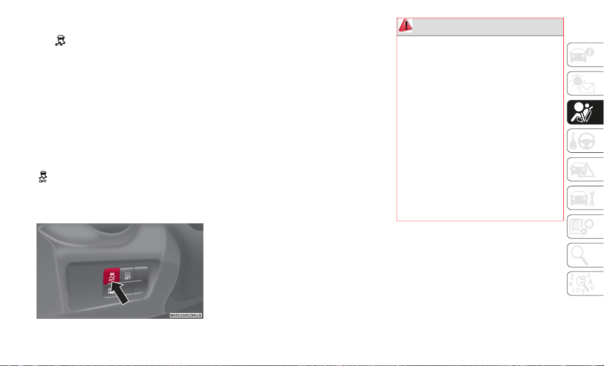
119
(Continued)
DSC OFF Indicator Light
The indicator light stays on for a few
seconds when the ignition is placed in the
ON
mode. It also illuminates when the DSC
OFF switch is pressed and TCS/DSC is
switched off.
If the light remains illuminated and the TCS/
DS
C is not switched off, contact your autho-
rized dealer. The DSC may have a malfunc-
tion.
DSC OFF Switch
Push the switch to turn off the TCS/DSC. The
indicator light in the instrument cluster
will illuminate. Push the switch again to turn
t
h
e TCS/DSC back on. The indicator light will
turn off.
DSC OFF Switch
NOTE:
When DSC is on and you attempt to free
the vehicle when it is stuck, or drive it out
on freshly fallen snow, the TCS (part of the
DSC system) will activate. Depressing the
accelerator will not increase engine power
and freeing the vehicle may be difficult.
When this happens, turn off the TCS/DSC.
If the TCS/DSC is off when the engine is
turned off, it automatically activates when
the ignition is placed in the ON mode.
WARNING!
Dynamic Stability Control (DSC) cannot
prevent the natural laws of physics from
acting on the vehicle, nor can it increase
the traction afforded by prevailing road
conditions. DSC cannot prevent acci
-
dents, including those resulting from
ex
cessive speed in turns, driving on very
slippery surfaces, or hydroplaning. DSC
also cannot prevent accidents resulting
from loss of vehicle control due to inap
-
propriate driver input for the conditions.
On
ly a safe, attentive, and skillful driver
can prevent accidents. The capabilities
of an DSC equipped vehicle must never
be exploited in a reckless or dangerous
manner which could jeopardize the
user’s safety or the safety of others.
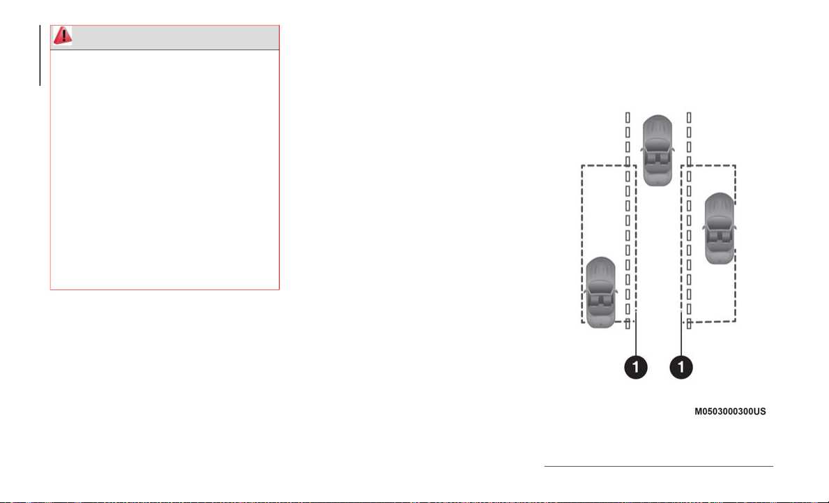
SAFETY
120
AUXILIARY DRIVING
SYSTEMS
Blind Spot Monitoring (BSM) System
The Blind Spot Monitoring (BSM) system is
designed to assist the driver during lane
changes by alerting the driver to the pres
-
ence of vehicles approaching from the rear in
an
adjacent lane.
The system detects vehicles approaching
fr
om the rear while traveling forward at a
speed of 19
mph (30 km/h) or faster, and
wi
ll activate the BSM warning lights
equipped within the door mirrors.
If the turn signal lever is operated to signal a
la
ne change in the direction in which the
warning light is illuminated, the system
warns the driver of a vehicle in the detection
area by flashing the warning light and acti
-
vating an audible alert.
The detection area on this system covers the
d
r
iving lanes on both sides of the vehicle and
from the rear part of the doors to about
164
ft (50 m) behind the vehicle.
BSM Detection Areas
Vehicle modifications, or failure to prop-
erly maintain your vehicle, may change
th
e handling characteristics of your
vehicle, and may negatively affect the
performance of the DSC system.
Changes to the steering system, suspen
-
sion, braking system, tire type and size
or
wheel size may adversely affect DSC
performance. Improperly inflated and
unevenly worn tires may also degrade
DSC performance. Any vehicle modifica
-
tion or poor vehicle maintenance that
re
duces the effectiveness of the DSC
system can increase the risk of loss of
vehicle control, vehicle rollover, personal
injury and death.
WARNING! (Continued)
1 — Detection Area

121
Activation / Deactivation
The Blind Spot Monitoring (BSM) system will
op
erate when all of the following conditions
are met:
The ignition is ON.
The BSM switch is pushed and the
warning light in the instrument cluster is
turned off.
The vehicle speed is 19 mph (30 km/h) or
faster.
The BSM system will not operate under the
fo
llowing conditions:
The vehicle speed falls below about
15 mph (25 km/h) even though the
wa
rning light is turned off.
The gear selector is shifted to REVERSE
(R).
In the following cases, the warning light in
th
e instrument cluster illuminates and oper-
ation of the BSM system is deactivated.
A problem with the system (including the
BSM warning lights) is detected.
A large change in position of a rear radar
sensor on the vehicle has occurred.
There is a large accumulation of snow or
ice on the rear bumper near a rear radar
sensor. Remove any snow, ice or mud on
the rear bumper.
Driving on snow covered roads for long
periods.
The temperature near the rear radar
sensors becomes extremely hot due to
driving for long periods on inclines during
warm weather.
The battery voltage has decreased.
If the warning light in the instrument cluster
re
mains illuminated, have the vehicle
inspected at an authorized dealer as soon as
possible.
NOTE:
Under the following conditions, the rear
ra
dar sensors cannot detect objects, or it
may be difficult to detect them:
A vehicle is in the detection area at the
rear in an adjacent driving lane but it does
not approach. The BSM system deter
-
mines the condition based on radar detec-
tion data.
A vehicle is traveling alongside your
vehicle at nearly the same speed for an
extended period of time.
Vehicles approaching in the opposite
direction.
A vehicle in an adjacent driving lane is
attempting to pass your vehicle.
A vehicle is in an adjacent lane on a road
with extremely wide driving lanes. The
detection area of the rear radar sensors is
set at the road width of expressways.
In the following cases, the activation of the
BS
M warning lights and the audible alert
may not occur, or they may be delayed:
A vehicle makes a lane change from a
driving lane two lanes over to an adjacent
lane
Driving on steep inclines
Crossing the summit of a hill or mountain
pass
The turning radius is small (making a
sharp turn or turning at intersections)
When there is a difference in the height
between your driving lane and the adja-
cent lane

SAFETY
122
Immediately after pushing the BSM switch
and the system becomes operable
If the road width is extremely narrow, vehi-
cles two lanes over may be detected. The
d
e
tection area of the rear radar sensors is set
according to the road width of expressways.
The BSM warning lights may turn on in reac-
tion to stationary objects on the road or the
ro
adside such as guardrails, tunnels, side-
walls, and parked vehicles. A BSM warning
l
i
ght may flash or the audible alert may be
activated several times when making a turn
at a city intersection.
Turn off the BSM system while pulling a
tr
ailer or while an accessory such as a bicycle
carrier is installed to the rear of the vehicle.
Otherwise, the radar’s sound system waves
will be blocked causing the system to not
operate normally.
In the following cases, it may be difficult to
vi
ew the illumination/flashing of the BSM
warning lights equipped on the door mirrors:
Snow or ice is adhering to the door mirrors.
The door glass is fogged or covered in
snow, frost or dirt.
The system switches to the Rear Cross
Tr
affic Alert function when the gear selector
is shifted to the REVERSE position.
BSM Warning Lights
The BSM warning lights are equipped on the
le
ft and right door mirrors.
BSM Warning Light
The warning lights turn on when a vehicle
ap
proaching from the rear in an adjacent
lane is detected.
When the ignition is placed in the ON posi-
tion, the malfunction warning light in the
in
strument cluster illuminates momentarily
and then turns off after a few seconds.
Forward Driving (BSM System Operation)
The BSM system detects vehicles
ap
proaching from the rear and turns on the
warning lights equipped on the door mirrors
according to the conditions.
Additionally, while a warning light is illumi-
nated, if the turn signal lever is operated to
s
i
gnal a turn in the direction in which the
warning light is illuminated, the warning
light flashes.
Reverse Driving (RCTA System Operation)
The Rear Cross Traffic Alert (RCTA) system
de
tects vehicles approaching from the left
and right of your vehicle and flashes the
BSM warning lights.
Function For Canceling Illumination Dimmer
When the headlight switch is in the or
position, the brightness of the Blind Spot
Monitoring (BSM) warning lights is dimmed.
If the Blind Spot Monitoring (BSM) warning
lights are difficult to see due to glare from
surrounding brightness when traveling on
snow-covered roads or under foggy condi
-
tions, push the dimmer cancellation button
t
o
cancel the dimmer and increase the
brightness of Blind Spot Monitoring (BSM)
warning lights when they turn on.
Refer to “Getting To Know Your Instrument
Pa
nel” for further information.
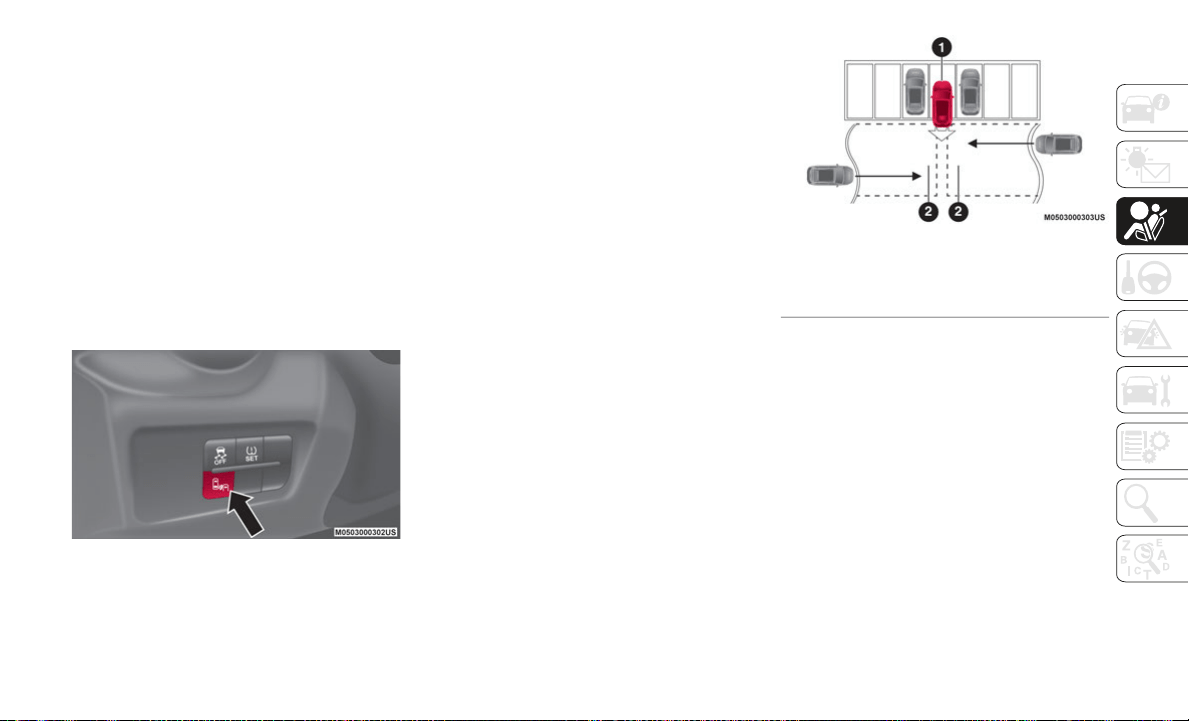
123
BSM Warning Beep
The BSM audible alert is activated simulta-
neously with the flashing of a BSM warning
li
ght.
BSM Switch
When the BSM switch is pushed, the BSM
a
n
d RCTA systems are turned off and the
BSM off indicator light in the instrument
cluster turns on.
If the switch is pushed again, the BSM and
RC
TA systems become operable and the
BSM off indicator light turns off.
BSM Switch Location
NOTE:
When the ignition is placed in the OFF
postion, the condition before the system
was turned off is maintained. For example,
if the ignition is placed in the OFF position
while the BSM and RCTA systems are
operational, the BSM and RCTA systems
remain operational the next time the igni
-
tion is placed in the ON position.
The BSM and RCTA systems are turned off
when the battery is disconnected such as
when the battery terminals or fuses have
been removed and reinstalled. To turn the
BSM and RCTA systems back on, push the
BSM switch.
Rear Cross Traffic Alert (RCTA) Function
The Rear Cross Traffic Alert (RCTA) system is
de
signed to assist the driver in checking the
area to the rear of the vehicle on both sides
while the vehicle is in REVERSE by alerting
the driver to the presence of vehicles
approaching the rear of the vehicle.
The RCTA system detects vehicles
ap
proaching from the left and right sides of
the vehicle while the vehicle is reversing out
of a parking space, and notifies the driver of
possible danger using the BSM warning
lights and an audible alert.
Rear Cross Traffic Alert
RCTA Operation
The RCTA system operates when the gear
s
e
lector is shifted to the REVERSE position.
If there is the possibility of a collision with an
ap
proaching vehicle, the BSM warning light
flashes and the audible alert is activated
simultaneously.
With Rear View Camera
The Rear Cross Traffic Alert (RCTA) warning
in
dication in the rearview monitor also
synchronizes with the Blind Spot Monitoring
(BSM) warning indicator light on the door
mirrors.
1 — Your Vehicle
2 — Approaching Vehicles Left And Right
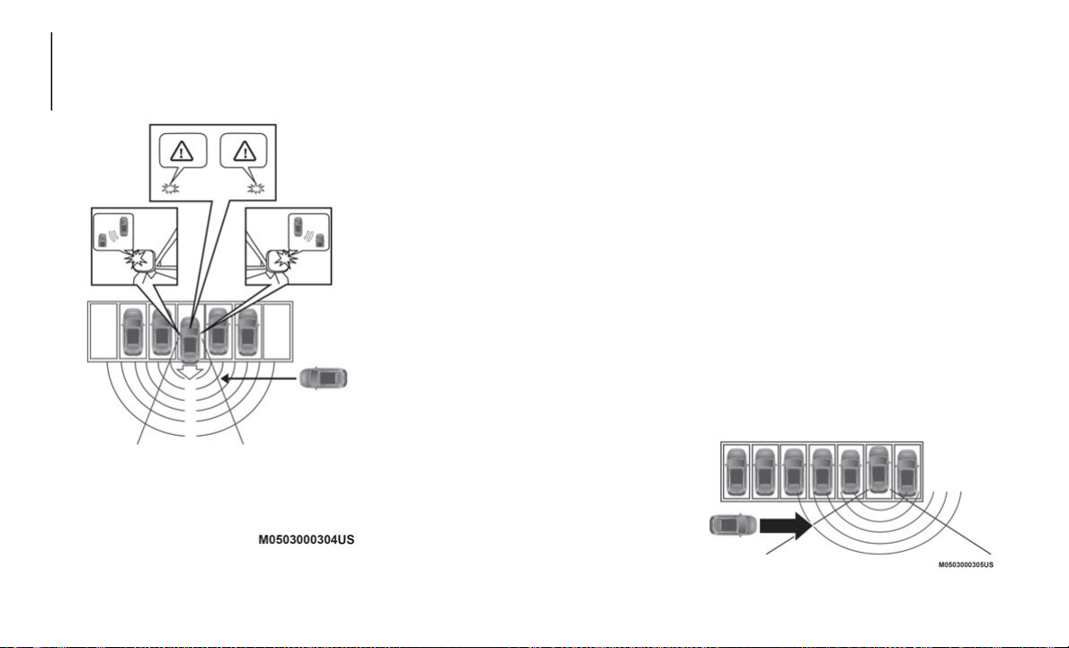
SAFETY
124
RCTA Detection
In the following cases, the BSM off indicator
li
ght turns on and operation of the system is
deactivated. If the BSM off indicator light in
the instrument cluster remains illuminated:
A problem with the system including the
BSM warning lights has occurred.
A large change in the position of a rear
radar sensor on the vehicle has occurred.
There is a large accumulation of snow or
ice on the rear bumper near a rear radar
sensor.
Driving on snow-covered roads for long
periods.
The temperature near the radar sensors
becomes extremely hot due to driving for
long periods on inclines during warm
weather.
The battery voltage has decreased.
Have the vehicle inspected at an authorized
de
aler as soon as possible.
NOTE:
Under the following conditions, the rear
ra
dar sensors cannot detect objects or it may
be difficult to detect them:
The vehicle speed while in REVERSE is
about 6 mph (10 km/h ) or faster.
The rear radar sensor detection area is
obstructed by a nearby wall or parked
vehicle (reverse the vehicle to a position
where the radar sensor detection area is no
longer obstructed).
A vehicle is approaching directly to the
rear of your vehicle.
The vehicle is parked on an incline.
Immediately after pushing the BSM switch
and the system becomes operable.
Sensors Obstructed By Nearby Vehicles
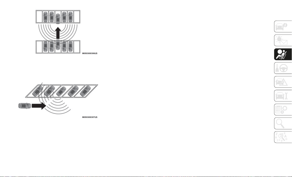
125
Another Vehicle Approaching Directly To The
Rear Of Your Vehicle
Your Vehicle Parked On An Incline
In the following cases, it may be difficult to
v
i
ew the illumination/flashing of the BSM
warning lights equipped on the door mirrors:
Snow or ice adheres to the door mirrors.
The door glass is fogged or covered in
snow, frost or dirt.
Turn off the RCTA system while pulling a
tr
ailer or while an accessory such as a bicycle
carrier is installed to the rear of the vehicle.
Otherwise, the sound system waves emitted
by
the radar will be blocked causing the
system to not operate normally.
General Information
The following regulatory statement applies to
all Radio Frequency (RF) devices equipped
in this vehicle:
This device complies with Part 15 of the FCC
Ru
les and with Innovation, Science and
Economic Development Canada
license-exempt RSS standard(s). Operation
is subject to the following two conditions:
1. This device may not cause harmful inter-
f
erence, and
2. This device must accept any interference
r
eceived, including interference that may
cause undesired operation.
Le présent appareil est conforme aux CNR
d`
Innovation, Science and Economic Devel-
opment applicables aux appareils radio
e
x
empts de licence. L'exploitation est
autorisée aux deux conditions suivantes:
1. l'appareil ne doit pas produire de brouil-
l
age, et
2. l'utilisateur de l'appareil doit accepter
t
out brouillage radioélectrique subi,
même si le brouillage est susceptible
d'en compromettre le fonctionnement.
La operación de este equipo está sujeta a las
si
guientes dos condiciones:
1. es posible que este equipo o dispositivo
n
o cause interferencia perjudicial y
2. este equipo o dispositivo debe aceptar
c
ualquier interferencia, incluyendo la
que pueda causar su operación no
deseada.
NOTE:
Changes or modifications not expressly
a
p
proved by the party responsible for compli-
ance could void the user’s authority to
o
p
erate the equipment.

SAFETY
126
TPMS (Tire Pressure Monitoring System)
Tire Pressure Monitoring System — Lo/Hi
Grade
The Tire Pressure Monitoring System (TPMS)
mo
nitors the air pressure of all four tires.
If the air pressure of one or more tires is too
lo
w, the system warns the driver by indi-
cating the warning light in the instrument
cluster and a beep sound.
The system monitors the tire pressures indi-
rectly using the data sent from the ABS
w
h
eel speed sensors.
To allow the system to operate correctly, the
sy
stem needs to be initialized with the spec-
ified tire pressure (value on the tire placard
l
a
bel). Follow the procedure and perform the
initialization (refer to “Tire Pressure Moni
-
toring System Initialization” paragraph).
The warning light flashes when the
system has a malfunction.
Because this system detects slight changes
in
tire conditions, the timing of the warning
may be faster or slower in the following
cases:
The size, manufacturer, or the type of tires
is different from the specification.
The size, manufacturer, or the type of a
tire is different from the others, or the
level of tire wear is excessively different
between them.
A run-flat tire, snow tire, or tire chains are
used.
An emergency tire is used (the warning
light may flash and then continue illumi-
nating).
A tire is repaired using the emergency flat
tire repair kit.
The tire pressure is excessively higher
than the specified pressure, or the tire
pressure is suddenly lowered for some
reason such as a tire burst during driving.
The vehicle speed is lower than about
9 mph (15 km/h) (including when the
ve
hicle is stopped), or the drive period is
shorter than five minutes.
The vehicle is driven on an extremely
rough road or a slippery, icy road.
Hard steering and rapid acceleration/
deceleration are repeated such as during
aggressive driving on a winding road.
Load on the vehicle is applied to a tire
such as by loading heavy luggage to one
side of the vehicle.
System initialization has not been imple-
mented with the specified tire pressure.
Tire Pressure Monitoring System Initialization
In the following cases, system initialization
m
u
st be performed so that the system oper-
ates normally:
A tire pressure is adjusted.
A tire rotation is performed. A tire or wheel
is replaced.
The battery is replaced or completely
discharged.
The warning light is illuminated.
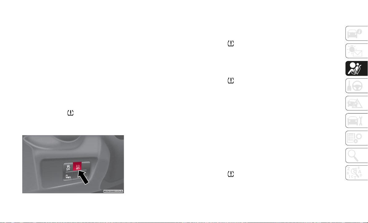
127
Initialization Method
Proceed as follows:
1. Park the car in a safe place and firmly
a
pply the parking brake.
2. Be sure the tires are cool, then adjust the
t
ire pressure of all four (4) tires to the
specified pressure indicated on the tire
placard label located on the driver's door
frame (door open).
3. Place the ignition in the ON mode.
4
. While the vehicle is parked, press and
h
old the TPMS system set switch and
verify that the warning light in the
instrument cluster flashes twice and a
b
e
ep sound is heard once.
TPMS Set Switch
NOTE:
If the system initialization is performed
without adjusting the tire pressure, the
system cannot detect the normal tire pres
-
sure and it may not illuminate the
warning light even if a tire pressure is low,
or it may illuminate the light even if the
pressures are normal.
Adjust the tire pressure on all four tires
and initialize the system when the
warning light is turned on. If the warning
light turns on for a reason other than a flat
tire, the tire pressure of all four tires may
have decreased naturally.
The system initialization will not be
performed if the switch is pressed while
the vehicle is being driven.
Tire Pressure Monitoring System — Abarth
The TPMS monitors the pressure for each
ti
re.
If tire pressure is too low in one or more tires,
th
e system will inform the driver via the
warning light in the instrument cluster and
by the warning beep sound.
The tire pressure sensors installed on each
wh
eel send tire pressure data by radio signal
to the receiver unit in the vehicle.
TPMS does not alleviate your need to check
th
e pressure and condition of all four tires
regularly.
Each tire, including the spare (if equipped),
sh
ould be checked monthly when cold and
inflated to the inflation pressure recom
-
mended by the vehicle manufacturer on the
ve
hicle placard or tire inflation pressure
label. (If your vehicle has tires of a different
size than the size indicated on the vehicle
placard or tire inflation pressure label, you
should determine the proper tire inflation
pressure for those tires.)
As an added safety feature, your vehicle has
be
en equipped with a Tire Pressure Moni-
toring System (TPMS) that illuminates a low
t
i
re pressure telltale when one or more of
your tires is significantly under-inflated.
Accordingly, when the low tire pressure tell
-
tale illuminates, you should stop and check
yo
ur tires as soon as possible, and inflate
them to the proper pressure. Driving on a
significantly under-inflated tire causes the
tire to overheat and can lead to tire failure.
Under-inflation also reduces fuel efficiency

SAFETY
128
and tire tread life, and may affect the
vehicle's handling and stopping ability.
Please note that the TPMS is not a substitute
for proper tire maintenance, and it is the
driver's responsibility to maintain correct tire
pressure, even if under-inflation has not
reached the level to trigger illumination of
the TPMS low tire pressure telltale.
Your vehicle has also been equipped with a
TP
MS malfunction indicator to indicate
when the system is not operating properly.
When the system detects a malfunction, the
telltale will flash for approximately one
minute and then remain continuously illumi
-
nated. This sequence will continue upon
s
u
bsequent vehicle start-ups as long as the
malfunction exists. When the malfunction
indicator is illuminated, the system may not
be able to detect or signal low tire pressure
as intended. TPMS malfunctions may occur
for a variety of reasons, including the instal
-
lation of replacement or alternate tires or
wh
eels on the vehicle that prevent the TPMS
from functioning properly. Always check the
TPMS malfunction telltale after replacing
one or more tires or wheels on your vehicle to
ensure that the replacement or alternate
tires and wheels allow the TPMS to continue
to function properly.
System Error Activation
When the warning light flashes, there may
be a system malfunction. Contact an autho-
rized dealer.
A system error activation may occur in the
f
o
llowing cases:
When there is equipment or a device near
the vehicle using the same radio
frequency as that of the tire pressure
sensors.
When a metallic device such as a
non-genuine navigation system is
equipped near the center of the dash
-
board, which may block radio signals from
th
e tire pressure sensor to the receiver
unit.
When using the following devices in the
vehicle that may cause radio interference
with the receiver unit.
A digital device such as a personal
computer.
A current converter device such as a
DC-AC converter.
When excess snow or ice adheres to the
vehicle, especially around the wheels.
When the tire pressure sensor batteries are
discharged.
When using a wheel with no tire pressure
sensor installed.
When using tires with steel wire reinforce-
ment in the side walls.
When using tire chains.
Tires And Wheels
NOTE:
When inspecting or adjusting the tire air
p
r
essures, do not apply excessive force to the
stem portion of the wheel unit. The stem
portion could be damaged.
Changing Tires And Wheels
The following procedure allows the TPMS to
re
cognize a tire pressure sensor's unique ID
signal code whenever tires or wheels are
changed, such as changing to and from
winter tires.

129
NOTE:
Each tire pressure sensor has a unique ID
signal code. The signal code must be
registered with the TPMS before it can
work. The easiest way to do it is to have an
authorized dealer change your tire and
complete ID signal code registration.
When an authorized dealer changes your
vehicle's tires, they will complete the tire
pressure sensor ID signal code registra
-
tion.
If you or someone else changes tires, you or
so
meone else can also undertake the steps
for the TPMS to complete the ID signal code
registration:
After tires have been changed, place the
ignition in the ON mode, then back to ACC
or OFF modes.
Wait for about 15 minutes.
After about 15 minutes, drive the vehicle
at a speed of at least 16 mph (25 km/h)
fo
r 20 minutes and the tire pressure
se
nsor ID signal code will be registered
automatically.
NOTE:
If the vehicle is driven within about
15
minutes of changing tires, the warning
light will flash because the sensor ID signal
co
de would not have been registered. If this
happens, park the vehicle for about
15
minutes, after which the sensor ID signal
co
de will register upon driving the vehicle for
20
minutes.
Replacing Tires And Wheels
NOTE:
When replacing/repairing the tires or
wheels or both, have the work done by an
authorized dealer, or the tire pressure
sensors may be damaged.
The wheels equipped on your vehicle are
specially designed for installation of the
tire pressure sensors. Do not use
non-genuine wheels, otherwise it may not
be possible to install the tire pressure
sensors.
Be sure to have the tire pressure sensors
in
stalled whenever tires or wheels are
replaced.
When having a tire or wheel or both replaced,
th
e following types of tire pressure sensor
installations are possible:
The tire pressure sensor is removed from
the old wheel and installed to the new one.
The same tire pressure sensor is used with
the same wheel. Only the tire is replaced.
A new tire pressure sensor is installed to a
new wheel.
NOTE:
The tire pressure sensor ID signal code
must be registered when a new tire pres-
sure sensor is purchased. For purchase of
a
tire pressure sensor and registration of
the tire pressure sensor ID signal code,
consult an authorized dealer.
When reinstalling a previously removed
tire pressure sensor to a wheel, replace the
grommet (seal between valve body/sensor
and wheel) for the tire pressure sensor.

SAFETY
130
General Information
The following regulatory statement applies to
all Radio Frequency (RF) devices equipped
in this vehicle:
This device complies with Part 15 of the FCC
Ru
les and with Innovation, Science and
Economic Development Canada
license-exempt RSS standard(s). Operation
is subject to the following two conditions:
1. This device may not cause harmful inter-
f
erence, and
2. This device must accept any interference
r
eceived, including interference that may
cause undesired operation.
Le présent appareil est conforme aux CNR
d`
Innovation, Science and Economic Devel-
opment applicables aux appareils radio
e
x
empts de licence. L'exploitation est
autorisée aux deux conditions suivantes:
1. l'appareil ne doit pas produire de brouil-
l
age, et
2. l'utilisateur de l'appareil doit accepter
t
out brouillage radioélectrique subi,
même si le brouillage est susceptible
d'en compromettre le fonctionnement.
La operación de este equipo está sujeta a las
si
guientes dos condiciones:
1. es posible que este equipo o dispositivo
n
o cause interferencia perjudicial y
2. este equipo o dispositivo debe aceptar
c
ualquier interferencia, incluyendo la
que pueda causar su operación no
deseada.
NOTE:
Changes or modifications not expressly
a
p
proved by the party responsible for compli-
ance could void the user’s authority to
o
p
erate the equipment.
OCCUPANT RESTRAINT
SYSTEMS
The most important safety equipment of the
vehicle comprise the following protection
systems:
Seat Belts
SBA (Seat Belt Alert) System
Head Restraints
Child Restraint Systems
Front Air Bags And Side Air Bags
CAUTION!
The TPMS has been optimized for the
original equipment tires and wheels.
TPMS pressures and warning have been
established for the tire size equipped on
your vehicle. Undesirable system opera
-
tion or sensor damage may result when
us
ing replacement equipment that is not
of the same size, type, and/or style. The
TPM sensor is not designed for use on
aftermarket wheels and may contribute
to a poor overall system performance or
sensor damage. Customers are encour
-
aged to use OEM wheels to assure proper
TP
M feature operation.
Using aftermarket tire sealants may
cause the Tire Pressure Monitoring
System (TPMS) sensor to become inop
-
erable. After using an aftermarket tire
se
alant it is recommended that you take
your vehicle to your authorized dealer to
have your sensor function checked.
After inspecting or adjusting the tire
pressure always reinstall the valve stem
cap. This will prevent moisture and dirt
from entering the valve stem, which
could damage the TPMS sensor.
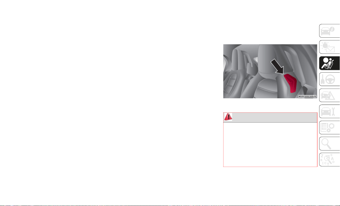
131
(Continued)
Read the information given in the following
pages with the utmost care.
It is of fundamental importance that the
pr
otection systems are used in the correct
way to guarantee the maximum possible
safety level for the driver and the passengers.
SEAT BELT SYSTEMS
Buckle up even though you are an excellent
driver, even on short trips. Someone on the
road may be a poor driver and could cause a
collision that includes you. This can happen
far away from home or on your own street.
Research has shown that seat belts save
li
ves, and they can reduce the seriousness of
injuries in a collision. Some of the worst inju
-
ries happen when people are thrown from the
ve
hicle. Seat belts reduce the possibility of
ejection and the risk of injury caused by
striking the inside of the vehicle. Everyone in
a motor vehicle should be belted at all times.
Seat Belt Precautions
Seat belts help to decrease the possibility of
severe injury during accidents and sudden
stops. FCA US LLC recommends that the
driver and passengers always wear seat belts.
Mexico
All the seats have lap/shoulder belts. These
be
lts have retractors with inertia locks that
keep them out of the way when not in use.
The locks allow the belts to remain comfort-
able on users, but they will lock in position
du
ring a collision.
Except Mexico
All of the seat belt retractors are designed to
k
e
ep the lap/shoulder belts out of the way
when not in use.
The driver's seat belt has no provisions for
ch
ild-restraint systems and has only an
emergency locking mode.
The driver may wear it comfortably, and it
wi
ll lock during a collision.
However, the passenger's seat lap/shoulder
be
lt retractor operates in two modes: emer-
gency locking mode, and for child-restraint
s
y
stems, automatic locking mode. If you
must use the passenger seat for a child, slide
the passenger seat as far back as possible
and make sure any child restraint system is
secured properly.
Belt retraction may become difficult if the
be
lts and seat belt guides are soiled, so try to
keep them clean. Refer to “Lap/Shoulder
Belt” in ”Interiors”, found in “Servicing And
Maintenance” for further information.
Seat Belt Routing Guide
WARNING!
Relying on the air bags alone could lead
to more severe injuries in a collision. The
air bags work with your seat belt to
restrain you properly. In some collisions,
the air bags won’t deploy at all. Always
wear your seat belt even though you have
air bags.

SAFETY
132
(Continued)
(Continued)
(Continued)
In a collision, you and your passengers
can suffer much greater injuries if you
are not properly buckled up. You can
strike the interior of your vehicle or other
passengers, or you can be thrown out of
the vehicle. Always be sure you and
others in your vehicle are buckled up
properly.
It is dangerous to ride in a cargo area,
inside or outside of a vehicle. In a colli-
sion, people riding in these areas are
m
o
re likely to be seriously injured or
killed.
Do not allow people to ride in any area of
your vehicle that is not equipped with
seats and seat belts.
Be sure everyone in your vehicle is in a
seat and using a seat belt properly.
Occupants, including the driver, should
always wear their seat belts whether or
not an air bag is also provided at their
seating position to minimize the risk of
severe injury or death in the event of a
crash.
WARNING! (Continued)
Wearing your seat belt incorrectly could
make your injuries in a collision much
worse. You might suffer internal injuries,
or you could even slide out of the seat
belt. Follow these instructions to wear
your seat belt safely and to keep your
passengers safe, too.
Two people should never be belted into a
single seat belt. People belted together
can crash into one another in a collision,
hurting one another badly. Never use a
lap/shoulder belt or a lap belt for more
than one person, no matter what their
size.
WARNING!
A lap belt worn too high can increase the
risk of injury in a collision. The seat belt
forces won’t be at the strong hip and
pelvic bones, but across your abdomen.
Always wear the lap part of your seat belt
as low as possible and keep it snug.
WARNING! (Continued)
A twisted seat belt may not protect you
properly. In a collision, it could even cut
into you. Be sure the seat belt is flat
against your body, without twists. If you
can’t straighten a seat belt in your
vehicle, take it to an authorized dealer
immediately and have it fixed.
A seat belt that is buckled into the wrong
buckle will not protect you properly. The
lap portion could ride too high on your
body, possibly causing internal injuries.
Always buckle your seat belt into the
buckle nearest you.
A seat belt that is too loose will not
protect you properly. In a sudden stop,
you could move too far forward,
increasing the possibility of injury. Wear
your seat belt snugly.
A seat belt that is worn under your arm is
dangerous. Your body could strike the
inside surfaces of the vehicle in a colli-
sion, increasing head and neck injury. A
se
at belt worn under the arm can cause
internal injuries. Ribs aren’t as strong as
shoulder bones. Wear the seat belt over
your shoulder so that your strongest
bones will take the force in a collision.
WARNING! (Continued)
133
(Continued)
Important Safety Precautions
Please pay close attention to the information
in this section. It tells you how to use your
restraint system properly, to keep you and
your passengers as safe as possible.
Here are some simple steps you can take to
mi
nimize the risk of harm from a deploying
air bag:
1. Children 12 years old and under should
a
lways ride buckled up in the rear seat of
a vehicle with a rear seat.
2. A child who is not big enough to wear the
v
ehicle seat belt properly (Refer to “Child
Restraints” in this section for further
information) must be secured in the
appropriate child restraint or belt-posi
-
tioning booster seat in a rear seating
po
sition.
3. If a child from 2 to 12 years old (not in a
r
ear-facing child restraint) must ride in
the front passenger seat, move the seat
as far back as possible and use the
proper child restraint. Refer to “Child
Restraints” in this section for further
information.
4. Never allow children to slide the shoulder
b
elt behind them or under their arm.
5. You should read the instructions
p
rovided with your child restraint to make
sure that you are using it properly.
6. All occupants should always wear their
l
ap and shoulder belts properly.
7. The driver and front passenger seats
s
hould be moved back as far as practical
to allow the front air bags room to inflate.
8. Do not lean against the door or window.
I
f your vehicle has side air bags, and
deployment occurs, the side air bags will
inflate forcefully into the space between
occupants and the door and occupants
could be injured.
9. If the air bag system in this vehicle needs
t
o be modified to accommodate a
disabled person, refer to the “Customer
Assistance” section for customer service
contact information.
A shoulder belt placed behind you will
not protect you from injury during a colli-
sion. You are more likely to hit your head
i
n
a collision if you do not wear your
shoulder belt. The lap and shoulder belt
are meant to be used together.
A frayed or torn seat belt could rip apart
in a collision and leave you with no
protection. Inspect the seat belt system
periodically, checking for cuts, frays, or
loose parts. Damaged parts must be
replaced immediately. Do not disas
-
semble or modify the seat belt system.
S
e
at belt assemblies must be replaced
after a collision.
WARNING! (Continued)
WARNING!
Never place a rear-facing child restraint
in front of an air bag. A deploying
passenger front air bag can cause death
or serious injury to a child 12 years or
younger, including a child in a
rear-facing child restraint.

SAFETY
134
Seat Belts And Pregnant Women
Pregnant Women And Persons With Serious
Medical Conditions
Pregnant women should always wear seat
be
lts. Ask your doctor for specific recom-
mendations.
The lap belt should be worn SNUGLY AND
A
S
LOW AS POSSIBLE OVER THE HIPS.
The shoulder belt should be worn across your
shoulder properly, but never across the
stomach area.
Seat Belts And Pregnant Women
Persons with serious medical conditions also
s
h
ould wear seat belts. Check with your
doctor for any special instructions regarding
specific medical conditions.
Emergency Locking Mode
When the seat belt is fastened, it will always
be in the emergency locking mode.
In the emergency locking mode, the belt
re
mains comfortable on the occupant and
the retractor will lock in position during a
collision.
If the belt is locked and cannot be pulled
ou
t, retract the belt once, and then try
pulling it out slowly. If this fails, pull the belt
strongly one time and loosen, then pull it out
again slowly.
Seat Belt With Automatic Locking Mode
When the seat belt is fastened, it will always
be
in the emergency locking mode until it is
switched to automatic locking mode by
pulling it all the way out to its full length.
If the belt feels tight and hinders comfort-
able movement while the vehicle is stopped
or
in motion, it may be in the automatic
locking mode because the belt has been
pulled too far out.
To return the belt to the more comfortable
em
ergency locking mode, wait until the
vehicle has stopped in a safe, level area,
retract the belt fully to convert it back to
emergency locking mode and then extend it
around you again.
Automatic Locking Mode
Always use the automatic locking mode to
ke
ep the child-restraint system from shifting
to an unsafe position in the event of an acci
-
dent.
To enable seat belt automatic locking mode,
pu
ll it all the way out and connect it as
instructed on the child restraint system. It
will retract down to the child restraint system
and stay locked on it.
Never install a rear-facing child restraint
in the front seat of a vehicle. Only use a
rear-facing child restraint in the rear
seat. If the vehicle does not have a rear
seat, do not transport a rear-facing child
restraint in that vehicle.
WARNING! (Continued)
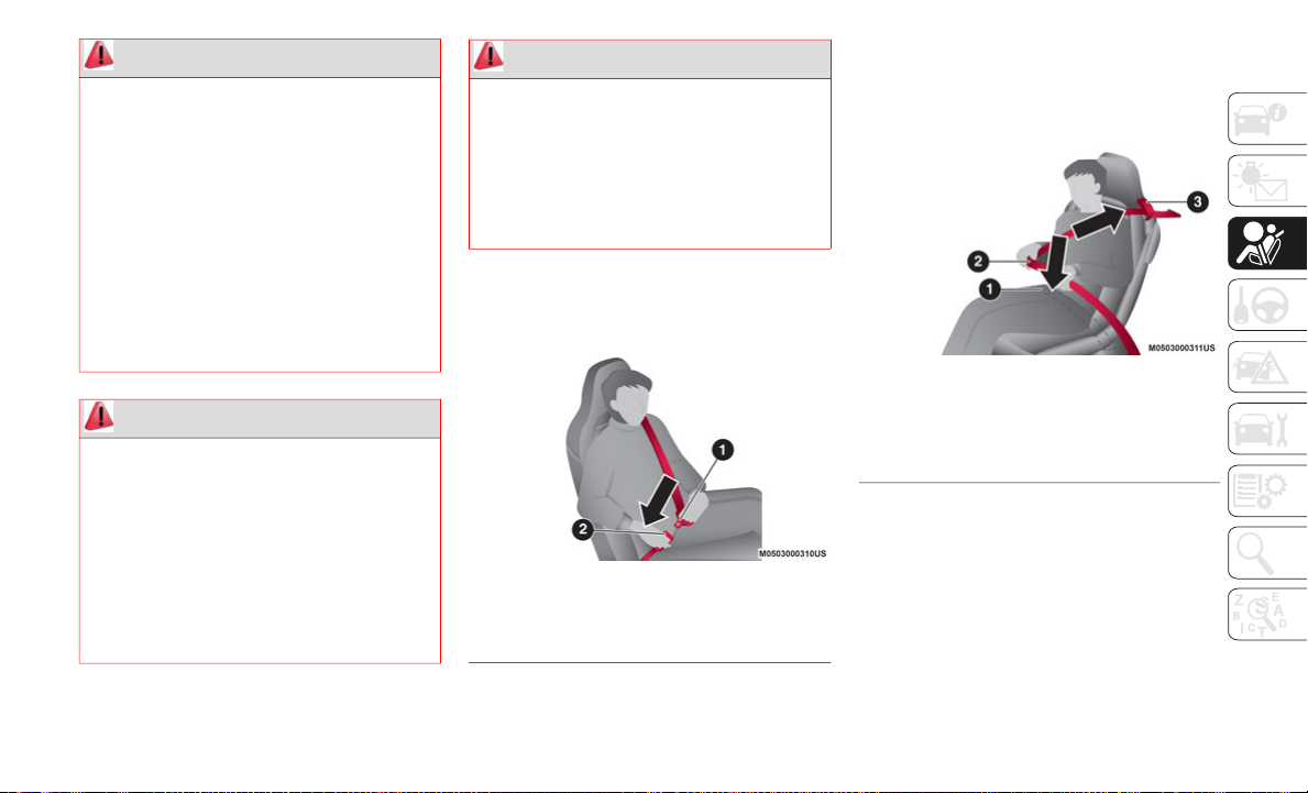
135
(Continued)
Lap/Shoulder Belts
Fastening The Seat Belt
Fastening The Seat Belt
Position the lap belt as low as possible, not
on
the abdominal area 2, then adjust the
shoulder belt 3 so that it fits snugly against
your body.
Adjusting The Seat Belt
WARNING!
Never place a rear-facing child restraint
in front of an air bag. A deploying
passenger front air bag can cause death
or serious injury to a child 12 years or
younger, including a child in a
rear-facing child restraint.
Never install a rear-facing child restraint
in the front seat of a vehicle. Only use a
rear-facing child restraint in the rear
seat. If the vehicle does not have a rear
seat, do not transport a rear-facing child
restraint in that vehicle.
WARNING!
The seat belt assembly must be replaced
if the switchable Automatic Locking
Retractor (ALR) feature or any other seat
belt function is not working properly
when checked according to the proce
-
dures in the Service Manual.
Failure to replace the seat belt assembly
could increase the risk of injury in colli-
sions.
Do not use the Automatic Locking Mode
to restrain occupants who are wearing
the seat belt or children who are using
booster seats. The locked mode is only
used to install rear-facing or
forward-facing child restraints that have
a harness for restraining the child.
1 — Seat Belt Tongue
2 — Seat Belt Buckle
WARNING! (Continued)
1 — Position Lap Belt Across Lap Area
2 — Lap Belt Routing
3 — Shoulder Belt Routing
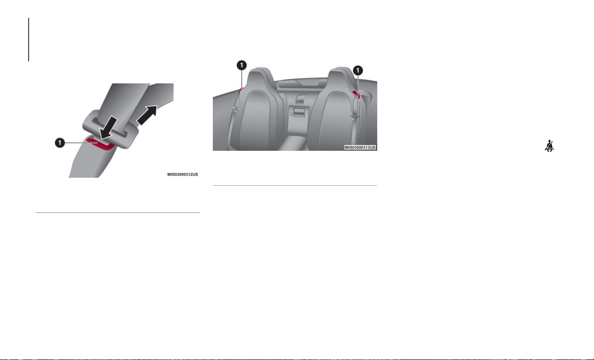
SAFETY
136
Unfastening The Seat Belt
Depress the button on the seat belt buckle.
If
the belt does not fully retract, pull it out
and check for kinks or twists. Then make
sure it remains untwisted as it retracts.
Latching/Unlatching The Seat Belt
NOTE:
If a belt does not fully retract, inspect it for
kinks and twists. If it is still not retracting
properly, have it inspected: contact an
authorized dealer.
Always wear the seat belt with it correctly
routed in its guide. Wearing a seat belt
without the seat belt routed in its guide is
dangerous because the seat belt would not
be able to provide adequate protection in
an accident, which could result in serious
injury.
Seat Belt Routing Guides
Seat Belt Warning Systems
If it detects that the occupant seat belt is
unfastened, the warning light or beep alerts
the occupant.
Refer to “Warning Lights And Messages” in
“G
etting To Knowing Your Instrument Panel”
for further information.
Refer to “Seat Belt Warning Light” in
“G
etting To Knowing Your Instrument Panel”
for further information.
Driver And Passenger BeltAlert (If
Equipped)
Seat Belt Warning Systems
The LED on dashboard trim turns on if the
dr
iver or passenger's seat is occupied and
the seat belt is not fastened with the ignition
cycled to on.
If the driver or passenger's seat belt is unfas-
tened (only when the passenger seat is occu-
pied) and the vehicle is driven at a speed
f
a
ster than about 12 mph (20 km/h), the
LED flashes. After a short time, the LED
stops flashing, but remains illuminated.
If a seat belt remains unfastened, the LED
fl
ashes again for a given period of time. In
this case, fasten the seat belt.
Seat Belt Pretensioner
For optimum protection, the driver and
passenger seat belts are equipped with
pretensioner and load limiting systems. For
both these systems to work properly you
must wear the seat belt properly.
The seat belt pretensioners are designed to
de
ploy in moderate or severe frontal, near
frontal collisions. In addition, during a side
collision, the pretensioner operates on the
1 — Seat Belt Release Button
1 — Shoulder Belt Routing Guides

137
side in which the collision occurs. The
pretensioners operate differently depending
on what types of air bags are equipped. For
details on the seat belt pretensioner opera
-
tion, refer to the “SRS Air Bag Deployment
Cr
iteria” paragraph in this chapter.
When a collision is detected, the preten-
sioners deploy simultaneously with the air
b
a
gs. For deployment details, refer to the
“SRS Air Bag Deployment Criteria” para
-
graph in this chapter.
The seat belt retractors remove slack quickly
as
the air bags are expanding. Any time the
air bags and seat belt pretensioners have
fired they must be replaced.
With Passenger Occupant Classification
Sy
stem
In addition, the pretensioner system for the
pa
ssenger, like the front and side passenger
Air Bag, is designed to only deploy when the
passenger occupant classification sensor
detects a passenger sitting on the
passenger's seat.
NOTE:
These devices are not a substitute for
proper seat belt placement by the occu-
pant. The seat belt still must be worn
s
n
ugly and positioned properly.
The pretensioners are triggered by the
Occupant Restraint Controller (ORC). Like
the air bags, the pretensioners are single
use items. A deployed pretensioner or a
deployed air bag must be replaced imme
-
diately.
Load Limiter
The load limiting system releases belt
webbing in a controlled manner to reduce
belt force on the occupant's chest.
While the most severe load on a seat belt
oc
curs in frontal collisions, the load limiter
has an automatic mechanical function and
can activate in any accident mode with suffi
-
cient occupant movement.
Even if the pretensioners have not fired, the
lo
ad limiting function must be checked by an
authorized dealer.
CHILD RESTRAINT
PRECAUTIONS
Child Restraints
FCA US LLC strongly urges the use of
child-restraint systems for children small
enough to use them.
Before buying any restraint system, make
su
re that it has a label certifying that it
meets all applicable Safety Standards. You
should also make sure that you can install it
in the vehicle where you will use it.
Everyone in your vehicle needs to be buckled
up
at all times, including babies and chil-
dren. Every state in the United States, and
e
v
ery Canadian province, requires that small
children ride in proper restraint systems.
This is the law, and you can be prosecuted
for ignoring it.
Check your local and state or provincial laws
fo
r specific requirements regarding the
safety of children riding in your vehicle.
Children 12 years or younger should ride
pr
operly buckled up in a rear seat, if avail-
able. According to crash statistics, children
are safer when properly restrained in the rear
seats rather than in the front.
SAFETY
138
Whatever child-restraint system you
consider, please pick the appropriate one for
the age and size of the child, obey the law
and follow the instructions that come with
the individual child-restraint system.
A child who has outgrown child-restraint
sy
stems should use seat belts, both lap and
shoulder. If the shoulder belt crosses the
neck or face, move the child closer to the
center of the vehicle.
A rear-facing child-restraint system should
NE
VER be used on the passenger seat with
the Air Bag system activated. In the event of
an impact the Air Bag activation may cause
fatal injuries to the transported child.
With Passenger Occupant Classification
Sy
stem
To reduce the chance of injuries caused by
de
ployment of the passenger Air Bag, the
Passenger Occupant Classification Sensor
work as a part of the Supplementary
Restraint System.
This system deactivates the passenger front
an
d side Air Bags and also the passenger
seat belt pretensioner system when the
OFF passenger Air Bag deactivation indicator
light illuminates.
When an infant or small child sits on the
pa
ssenger seat, the system shuts off the
passenger front and side Air Bags and seat
belt pretensioner system, so make sure the
OFF
passenger Air Bag deactivation indi-
cator light illuminates. For more details,
re
fer to "Passenger Occupant Classification
Sensor" in “Supplementary Restraint System
SRS — Air Bag” for additional information.
NOTE:
A seat belt or child-restraint system can
be
come very hot in a closed vehicle during
warm weather. To avoid burning yourself or a
child, check them before you or your child
touches them.
WARNING!
In a collision, an unrestrained child can
become a projectile inside the vehicle. The
force required to hold even an infant on
your lap could become so great that you
could not hold the child, no matter how
strong you are. The child and others could
be badly injured or killed. Any child riding
in your vehicle should be in a proper
restraint for the child’s size.
WARNING!
Improper installation can lead to failure
of an infant or child restraint. It could
come loose in a collision. The child
could be badly injured or killed. Follow
the child restraint manufacturer’s direc
-
tions exactly when installing an infant or
ch
ild restraint.
After a child restraint is installed in the
vehicle, do not move the vehicle seat
forward or rearward because it can
loosen the child restraint attachments.
Remove the child restraint before
adjusting the vehicle seat position.
When the vehicle seat has been
adjusted, reinstall the child restraint.
When your child restraint is not in use,
secure it in the vehicle with the seat belt
or remove it from the vehicle. Do not
leave it loose in the vehicle. In a sudden
stop or accident, it could strike the occu
-
pants or seatbacks and cause serious
pe
rsonal injury.
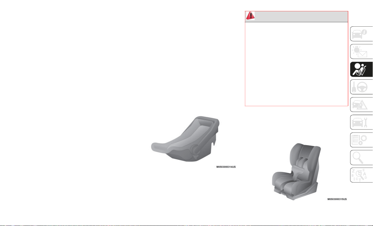
139
Child Restraint System Types
In this Owner’s Manual, explanation of child
restraint systems secured with seat belts is
provided for the following three types of
popular child-restraint systems: infant seat,
child seat, booster seat.
NOTE:
Installation position is determined by the
type of child restraint system. Always read
the manufacturer's instructions and this
Owner’s Manual carefully.
Due to variations in the design of child
restraint systems, vehicle seats and seat
belts, not all child restraint may fit all
seating positions.
Before purchasing a child-restraint
system, it should be tested in the specific
vehicle seating position (or positions)
where it is intended to be used. If a previ
-
ously purchased child-restraint system
do
es not fit, you may need to purchase a
different one that will.
NOTE:
For additional information, refer to
www.nhtsa.gov/parents-and-caregivers or
call: 1
–888–327–4236
Canadian residents should refer to Transport
Canada’s website for additional information:
http://www.tc.gc.ca/eng/motorvehiclesafety/
safedrivers-childsafety-index-53.htm
Infant Seat
An infant seat provides restraint by bracing
th
e infant's head, neck and back against the
seating surface.
Infant Seat
Child Seat
A child seat restrains a child's body using the
ha
rness.
Child Seat
WARNING!
Never place a rear-facing child restraint
in front of an air bag. A deploying
passenger Front Air Bag can cause death
or serious injury to a child 12 years or
younger, including a child in a
rear-facing child restraint.
Never install a rear-facing child restraint
in the front seat of a vehicle. Only use a
rear-facing child restraint in the rear
seat. If the vehicle does not have a rear
seat, do not transport a rear-facing child
restraint in that vehicle.
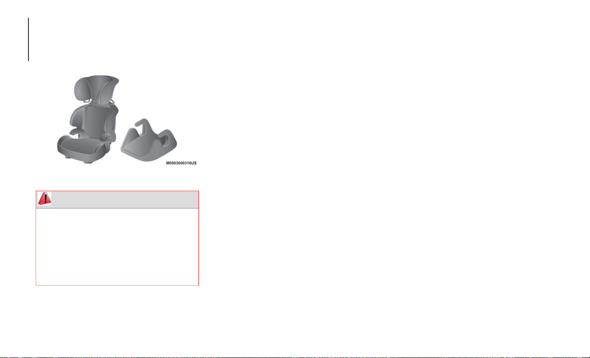
SAFETY
140
Booster Seat
A booster seat is a child restraint accessory
de
signed to improve the fit of the seat belt
system around the child's body.
Booster Seat
Child Seat Installation Position
The passenger lap/shoulder belt can easily
be converted into the automatic locking
mode, which must be done to hold the
child-restraint system.
NOTE:
To check if your seats have side air bags: FCA
US
LLC vehicles equipped with side air bag
will have an embossed "SRS AIRBAG"
marking on the outboard shoulder of the
seats.
Follow the child restraint system manufac-
turer's instructions carefully. Depending on
t
h
e type of child restraint system, it may not
employ seat belts which are in automatic
locking mode, however if it uses an upper
tether, it may not be mounted properly in this
vehicle as there is no safe way to anchor the
tether. Confirm whether the child restraint
system can be used with seat belts by
reading the child restraint system manufac
-
turer's instructions.
Passenger Seat Child Restraint System Installa-
tion (With Passenger Occupant Classification
S
y
stem)
NOTE:
Child restraint systems are designed to be
s
e
cured in vehicle seats by lap belts or the
lap belt portion of a lap/shoulder belt.
Proceed as follows:
Make sure the ignition is cycled off.
Slide the seat as far back as possible.
Place the child-restraint system on the
seat without putting your weight on the
seat and secure the child-restraint system
with the lap portion of the lap/shoulder
belt. See the manufacturer's instructions
on the child-restraint system for belt
routing instructions.
To get the retractor into the automatic
locking mode, pull the shoulder belt
portion of the seat belt until the entire
length of the belt is out of the retractor.
WARNING!
Never allow a child to put the shoulder
belt under an arm or behind their back. In
a crash, the shoulder belt will not protect a
child properly, which may result in serious
injury or death. A child must always wear
both the lap and shoulder portions of the
seat belt correctly.
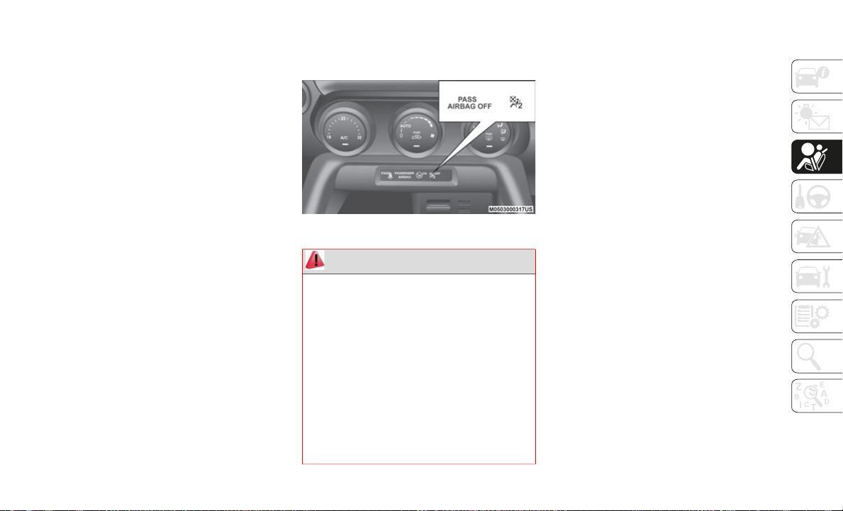
141
Push the child-restraint system firmly into
the vehicle seat. Be sure the belt retracts
as snugly as possible. A clicking noise
from the retractor will be heard during
retraction if the system is in automatic
locking mode. If the belt does not lock the
seat down tight, repeat the previous step
and also this one.
Seat your child safely in the child-restraint
system and secure the child according to
the instructions from the child-restraint
system manufacturer.
NOTE:
Inspect this function before each use of the
ch
ild restraint system. You should not be
able to pull the shoulder belt out of the
retractor while the system is in the automatic
locking mode. When you remove the
child-restraint system, be sure the belt fully
retracts to return the system to emergency
locking mode before occupants use the seat
belts.
Place the ignition in ON mode and make
sure the passenger air bag deactivation
indicator light illuminates after installing
a child restraint system on the passenger
seat. If the passenger air bag deactivation
indicator light does not illuminate, remove
the child restraint system, cycle the igni
-
tion to OFF mode, and then reinstall the
ch
ild restraint system.
Passenger Air Bag Deactivation Light
SUPPLEMENTARY
RESTRAINT SYSTEM SRS —
AIR BAG
Description
The front and side Supplementary Restraint
Systems (SRS) include different types of Air
Bags.
NOTE:
Please verify which kinds of Air Bags are
eq
uipped on your vehicle by locating the
“SRS AIR BAG” location indicators.
These indicators are visible in the area where
th
e Air Bags are installed.
The Air Bags are installed in the following
lo
cations:
The steering wheel hub (Driver Air Bag)
The passenger dashboard (Passenger Air
Bag)
The outer sides of the seat backs (Side Air
Bags)
WARNING!
Never place a rear-facing child restraint
in front of an air bag. A deploying
passenger Advanced Front Air Bag can
cause death or serious injury to a child
12 years or younger, including a child in
a rear-facing child restraint.
Never install a rear-facing child restraint
in the front seat of a vehicle. Only use a
rear-facing child restraint in the rear
seat. If the vehicle does not have a rear
seat, do not transport a rear-facing child
restraint in that vehicle.
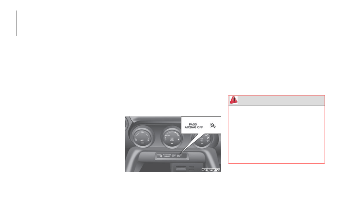
SAFETY
142
(Continued)
This vehicle has front air bags and lap/
shoulder belts for both the driver and front
passenger. The front air bags are a supple
-
ment to the seat belt restraint systems.
The Air Bag supplementary restraint systems
ar
e designed to provide supplementary
protection in certain situations so seat belts
are always important in the following ways.
Without seat belt usage, the Air Bags cannot
pr
ovide adequate protection during an acci-
dent. Seat belt usage is necessary to:
Keep the occupant from being thrown into
an inflating Air Bag.
Reduce the possibility of injuries during
an accident that is not designed for Air
Bag inflation, such as roll-over or rear
impact.
Reduce the possibility of injuries in
frontal, near frontal or side collisions that
are not severe enough to activate the Air
Bags.
Reduce the possibility of being thrown
from your vehicle.
Reduce the possibility of injuries to lower
body and legs during an accident because
the Air Bags provide no protection to these
parts of the body.
Hold the driver in a position which allows
better control of the vehicle.
If your vehicle is also equipped with a
pa
ssenger occupant classification system,
refer to the “Passenger Occupant Classification
System” paragraph for further information.
If your vehicle is equipped with a passenger
oc
cupant classification system, the
passenger Air Bag deactivation indicator
light illuminates for a specified time after
the ignition has been cycled ON.
Passenger Air Bag Deactivated Light
Small children must be protected by a
c
h
ild-restraint system as stipulated by law in
every state and province. In certain states
and provinces, larger children must use a
child-restraint system. Carefully consider
which child-restraint system is necessary for
your child and follow the installation direc
-
tions in this Owner's Manual as well as the
ch
ild-restraint system manufacturer's
instructions.
Do not use a child-restraint system which
em
ploys an upper tether because there is no
appropriate means to anchor the tether.
WARNING!
If the Indicator Light remains illumi-
nated for an adult passenger, have an
au
thorized dealer service the air bag
system immediately. Failure to do so
may cause serious injury or death. If the
Indicator Light is illuminated with the
words “PASS AIRBAG OFF,” the
Passenger Advanced Front Air Bag will
not deploy in the event of a collision.

143
Never place a rear-facing child restraint
in front of an air bag. A deploying
passenger front air bag can cause death
or serious injury to a child 12 years or
younger, including a child in a
rear-facing child restraint.
Never install a rear-facing child restraint
in the front seat of a vehicle. Only use a
rear-facing child restraint in the rear
seat. If the vehicle does not have a rear
seat, do not transport a rear-facing child
restraint in that vehicle.
Children 12 years or younger should
always ride buckled up in a vehicle with
a rear sea
WARNING! (Continued)
WARNING!
Unapproved modifications or service
procedures to the passenger seat
assembly, its related components, seat
cover or cushion may inadvertently
change the air bag deployment in case of
a frontal collision. This could result in
death or serious injury to the front
passenger if the vehicle is involved in a
collision. A modified vehicle may not
comply with required Federal Motor
Vehicle Safety Standards (FMVSS) and/
or Canadian Motor Vehicle Safety Stan
-
dards (CMVSS).
If it is necessary to modify the air bag
system for persons with disabilities,
contact an authorized dealer.
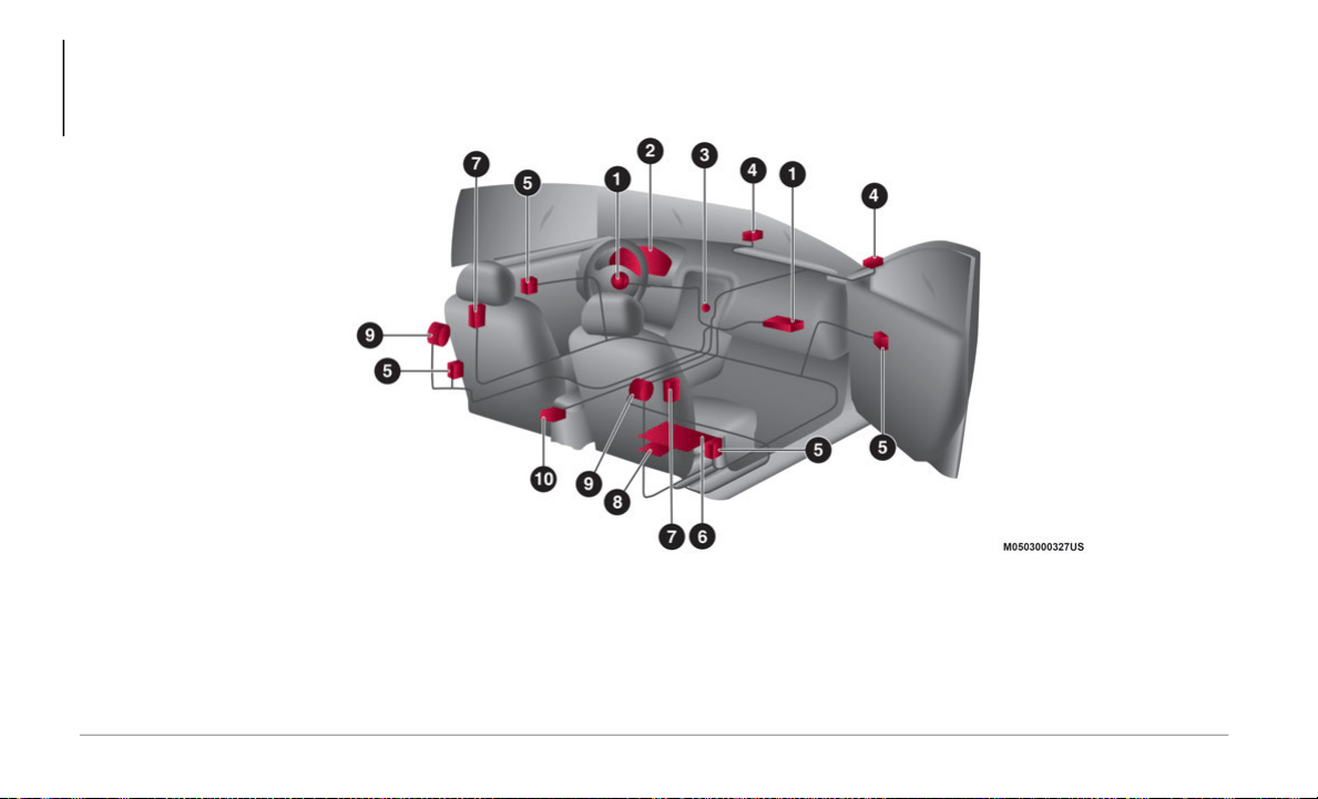
SAFETY
144
Supplementary Restraint System Components
With Passenger Occupant Classification System
With Passenger Occupant Classification System
1 — Driver/Passenger Inflators And Air Bags 6 — Passenger Occupant Classification Sensor
2 — Air Bag/Seat Belt Pretensioner System Warning Light 7 — Side Inflators And Air Bags
3 — Passenger Air Bag Deactivation Indicator Light 8 — Passenger Occupant Classification Module
4 — Front Air Bag Sensors 9 — Seat Belt Pretensioners
5 — Side Crash Sensors 10 — Crash Sensors And Diagnostic Module (Sas Unit)
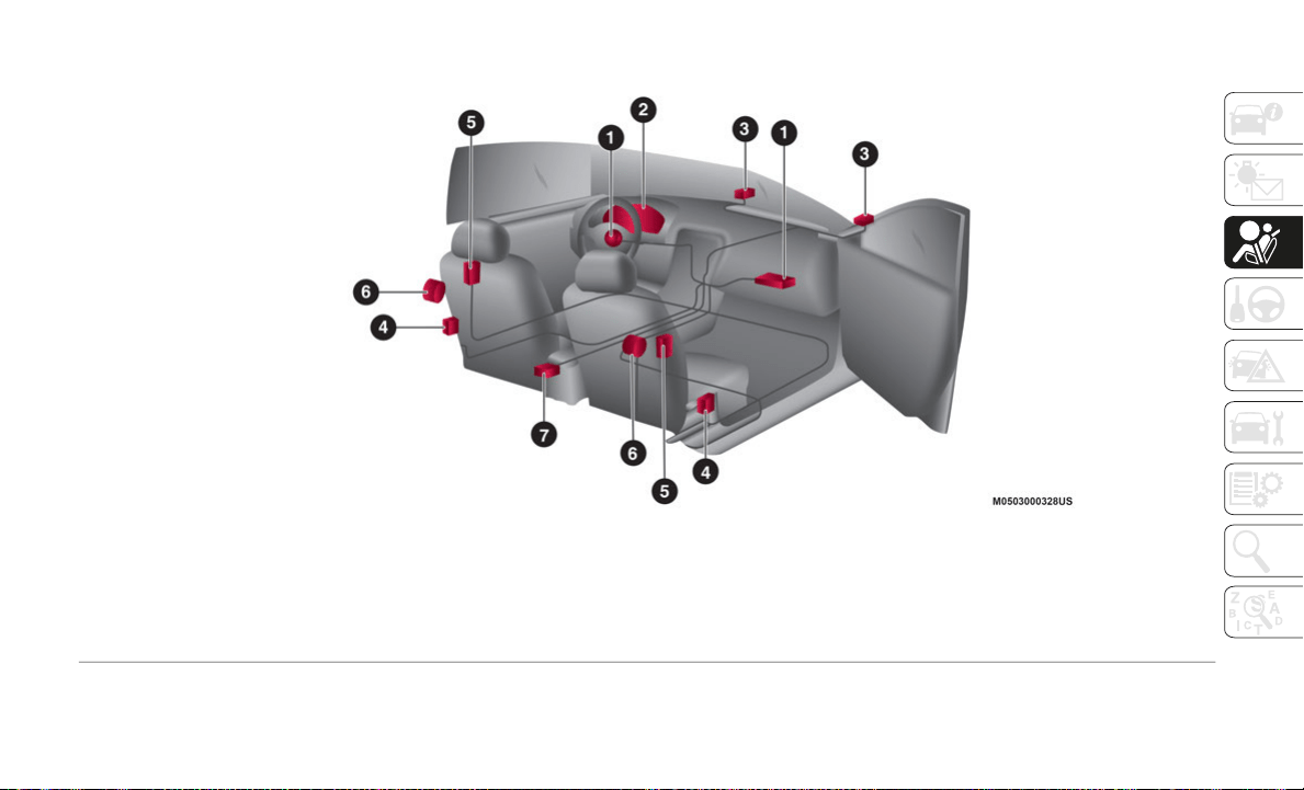
145
Without Passenger Occupant Classification System
Without Passenger Occupant Classification System
1 — Driver/Passenger Inflators And Air Bags 5 — Side Inflators And Air Bags
2 — Air Bag/Seat Belt Pretensioner System Warning Light 6 — Seat Belt Pretensioners
3 — Front Air Bag Sensors 7 — Crash Sensors And Diagnostic Module (Sas Unit)
4 — Side Crash Sensors
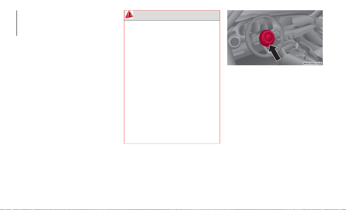
SAFETY
146
How The SRS Air Bags Work
This vehicle has front air bags and lap/
shoulder belts for both the driver and front
passenger. The front air bags are a supple
-
ment to the seat belt restraint systems. The
SR
S Air Bags are designed to provide further
protection for passengers in addition to the
seat belt functions. Be sure to wear seat
belts properly.
Seat Belt Pretensioners
The seat belt pretensioners are designed to
d
e
ploy in moderate or severe frontal, near
frontal collisions. In addition, during a side
collision, the pretensioner operates on the
side in which the collision occurs.
The pretensioners operate differently
de
pending on what types of air bags are
equipped. For details on the seat belt preten
-
sioner operation, refer to the “SRS Air Bag
De
ployment Criteria”.
Driver Air Bag
The driver's air bag is mounted in the
s
t
eering wheel.
Driver Side Air Bags
When Air Bag crash sensors detect a frontal
im
pact of greater than moderate force, the
driver's Air Bag inflates quickly helping to
reduce injury mainly to the driver's head or
chest caused by directly hitting the steering
wheel. For more details about Air Bag
deployment, refer to "SRS Air Bag Deploy
-
ment Criteria" in this chapter for further
in
formation.
(With Passenger Occupant Classification
Sy
stem)
The driver's dual-stage air bag controls air
ba
g inflation in two energy stages. During an
impact of moderate severity, the driver's air
bag deploys with lesser energy, whereas
during more severe impacts, it deploys with
more energy.
WARNING!
Being too close to the steering wheel or
instrument panel during front air bag
deployment could cause serious injury,
including death. Air bags need room to
inflate. Sit back, comfortably extending
your arms to reach the steering wheel or
instrument panel.
Never place a rear-facing child restraint
in front of an air bag. A deploying
passenger front air bag can cause death
or serious injury to a child 12 years or
younger, including a child in a
rear-facing child restraint.
Never install a rear-facing child restraint
in the front seat of a vehicle. Only use a
rear-facing child restraint in the rear
seat. If the vehicle does not have a rear
seat, do not transport a rear-facing child
restraint in that vehicle.
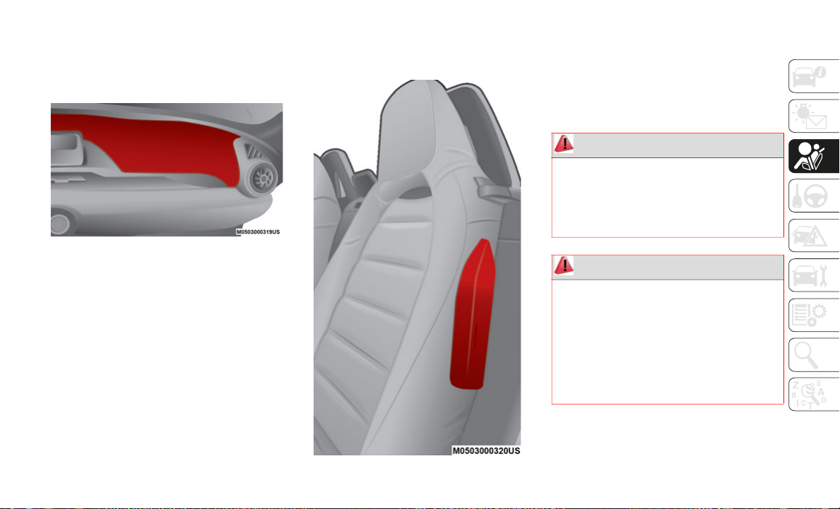
147
(Continued)
Passenger Air Bag
(Dual Stage)
The passenger Air Bag is mounted in the
pa
ssenger dashboard.
Passenger Side Air Bag
The inflation mechanism for the passenger
A
i
r Bag is the same as the driver's Air Bag, as
mentioned above. For more details about Air
Bag deployment, refer to "SRS Air Bag
Deployment Criteria" in this chapter.
For further details about air bag deployment,
re
fer to "SRS Air Bag Deployment Criteria" in
this chapter.
Side Air Bags
The side air bags are mounted in the outer
si
des of the seat backs. When the air bag
crash sensors detect a side impact of greater
than moderate force, the system inflates the
side air bag only on the side in which the
vehicle was hit.
Side Air Bags
The side air bag inflates quickly to reduce
in
jury to the driver or passenger's head and
chest caused by directly hitting interior parts
such as a door or window. For more details
about air bag deployment, refer to "SRS Air
Bag Deployment Criteria" in this chapter for
further information.
WARNING!
Do not use accessory seat covers or place
objects between you and the Side Air
Bags; the performance could be adversely
affected and/or objects could be pushed
into you, causing serious injury.
WARNING!
Occupants, including children, who are
up against or very close to Side Air Bags
can be seriously injured or killed. Occu
-
pants, including children, should never
le
an on or sleep against the door, side
windows, or area where the side air bags
inflate, even if they are in an infant or
child restraint.

SAFETY
148
(Continued)
(Continued)
With Passenger Occupant Classification
System
In addition, the passenger side bag is
de
signed to only deploy when the passenger
occupant classification sensor detects a
passenger sitting on the passenger's seat.
Warning Light/Beep
A system malfunction or operation condi-
tions are indicated by a warning. Refer to the
b
e
ginning paragraph of “Warning Lights And
Messages” in “Getting To Know Your Instru
-
ment Panel” for further information.
Seat belts (and child restraints where
appropriate) are necessary for your
protection in all collisions. They also
help keep you in position, away from an
inflating Side Air Bag. To get the best
protection from the Side Air Bags, occu
-
pants must wear their seat belts properly
a
n
d sit upright with their backs against
the seats. Children must be properly
restrained in a child restraint or booster
seat that is appropriate for the size of the
child.
WARNING!
Side Air Bags need room to inflate. Do
not lean against the door or window. Sit
upright in the center of the seat.
Being too close to the Side Air Bags
during deployment could cause you to be
severely injured or killed.
WARNING! (Continued)
Relying on the Side Air Bags alone could
lead to more severe injuries in a colli-
sion. The Side Air Bags work with your
s
e
at belt to restrain you properly. In
some collisions, Side Air Bags won’t
deploy at all. Always wear your seat belt
even though you have Side Air Bags.
WARNING!
If a child restraint system, child, small
teenager or adult in the front passenger
seat is seated improperly, the occupant
may provide an output signal to the OCS
that is different from the occupant’s
properly seated weight input. This may
result in serious injury or death in a colli
-
sion.
WARNING! (Continued)
Always wear your seat belt and sit prop-
erly, with the seatback in an upright
po
sition, your back against the seatback,
sitting upright, facing forward, in the
center of the seat, with your feet
comfortably on or near the floor.
Do not carry or hold any objects (e.g.,
backpacks, boxes, etc.) while seated in
the front passenger seat. Holding an
object may provide an output signal to
the OCS that is different than the occu
-
pant’s properly seated weight input,
wh
ich may result in serious injury or
death in a collision.
Placing an object on the floor under the
front passenger seat may prevent the
OCS from working properly, which may
result in serious injury or death in a colli
-
sion. Do not place any objects on the
fl
oor under the front passenger seat.
WARNING! (Continued)
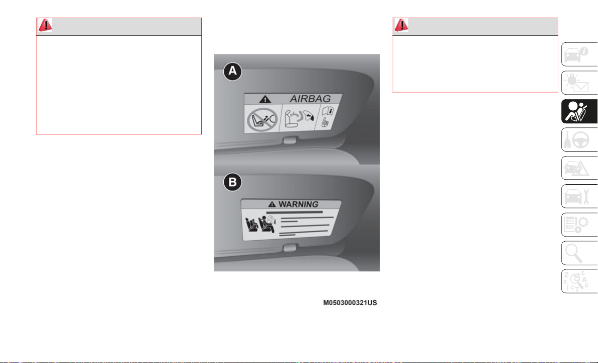
149
Passenger Side Front Air Bag And Child
Restraint Systems
Rearward-facing child restraint systems
mu
st NEVER be fitted on the front seat with
an active passenger side air bag since in the
event of an impact the air bag activation may
cause fatal injuries to the transported child.
ALWAYS comply with the instructions on the
l
abel stuck on the passenger side sun visor :
A = Mexico market/B = US and Canada
market.
Sun Visor Air Bag Labels
SRS Air Bag Deployment Criteria
This chart indicates the applicable SRS
equipment that will deploy depending on the
type of collision (the illustrations are the
representative cases of collisions).
Deployed air bags and seat belt preten-
sioners cannot protect you in another colli-
sion. Have the air bags, seat belt
p
r
etensioners, and the seat belt retractor
assemblies replaced by an authorized dealer
immediately. Also, have the Occupant
Restraint Controller System serviced as well.
WARNING!
Ignoring the Air Bag Warning Light in your
instrument panel could mean you won’t
have the air bags to protect you in a
collision. If the light does not come on as
a bulb check when the ignition is first
turned on, stays on after you start the
vehicle, or if it comes on as you drive, have
an authorized dealer service the air bag
system immediately.
WARNING!
Do not use accessory seat covers or place
objects between you and the Side Air
Bags; the performance could be adversely
affected and/or objects could be pushed
into you, causing serious injury.
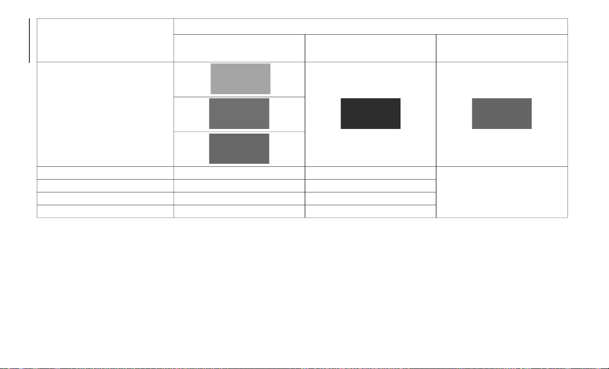
SAFETY
150
X: the SRS air bag equipment is designed to deploy in a collision.
(*) In a side collision, the seat belt pretensioners and the side air bags deploy (only on the side in which the collision occurs).
(**) Passenger Occupant Classification System:
the passenger front and side air bags and the seat belt pretensioner are designed to deploy when the
passenger occupant classification sensor detects a passenger sitting on the passenger's seat.
NOTE:
In a frontal offset collision, the equipped air
ba
gs and pretensioners may all deploy
depending on the direction, angle, and rate
of impact.
SRS Equipment
Types Of Collision
A Severe Frontal/Near Frontal
Collis
ion
A Severe Side Collision (*) A Rear Collision
SRS Equipment
Seat Belt Pretensioner X (**) (Both Sides) X (**) (Impact Side Only)
No air bag and seat belt
p
r
etensioner will be activated in
a rear collision
Driver Air Bag X
Passenger Air Bag X (**)
Side Air Bag X (**) (Impact Side Only)
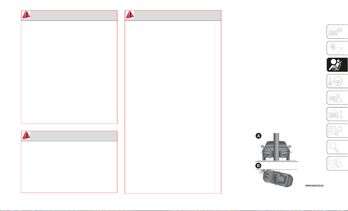
151
Limitations To SRS Air Bag
In severe collisions such as those described
in "SRS Air Bag Deployment Criteria" para-
graph, the applicable SRS air bag equipment
w
i
ll deploy.
However, in some accidents, the equipment
ma
y not deploy depending on the type of
collision and its severity.
Limitations To Front / Near Front Collision
De
tection
Front/near front collisions may not be
de
tected as severe enough to deploy the SRS
air bag equipment:
Impacts involving trees or poles (A)
Frontal offset impact to the vehicle (B)
Rear-ending or running under a truck's tail gate
Front/Near Front Collision
WARNING!
Unapproved modifications or service
procedures to the passenger seat
assembly, its related components, seat
cover or cushion may inadvertently
change the air bag deployment in case of
a frontal collision. This could result in
death or serious injury to the front
passenger if the vehicle is involved in a
collision. A modified vehicle may not
comply with required Federal Motor
Vehicle Safety Standards (FMVSS) and/
or Canadian Motor Vehicle Safety Stan
-
dards (CMVSS).
If it is necessary to modify the air bag
system for persons with disabilities,
contact an authorized dealer.
WARNING!
Deployed air bags and seat belt
pretensioners cannot protect you in
another collision. Have the air bags, seat
belt pretensioners, and the seat belt
retractor assemblies replaced by an
authorized dealer immediately. Also, have
the Occupant Restraint Controller System
serviced as well.
WARNING!
Ignoring the Air Bag Warning Light in
your instrument panel could mean you
won’t have the air bags to protect you in
a collision. If the light does not come on
as a bulb check when the ignition is first
turned on, stays on after you start the
vehicle, or if it comes on as you drive,
have an authorized dealer service the air
bag system immediately.
Placing an object on the floor under the
front passenger seat may prevent the
occupant classification sensor from
working properly, which may result in
serious injury or death in a collision. Do
not place any objects on the floor under
the front passenger seat.
If there is a fault present in the occupant
classification sensor, both the Indicator
Light and the Air Bag Warning Light will
illuminate to show that the Passenger
Advanced Front Air Bag is deactivated.
Should this occur, the Passenger
Advanced Front Air Bag will remain
deactivated until the fault is cleared.
This indicates that you should take the
vehicle to an authorized dealer for
service immediately.
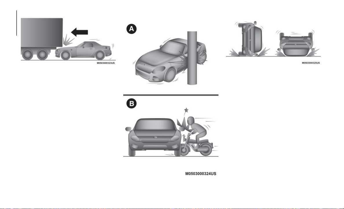
SAFETY
152
Rear End Collision
Limitations To Side Collision Detection
Side collisions may not be detected as severe
e
n
ough to deploy the SRS air bag equip-
ment:
Side impacts involving trees or poles (A)
Side impacts with two-wheeled vehicles
(B)
Roll-over
Side Collision
Roll-Over Collision
Passenger Occupant Classification Sensor
Your vehicle is equipped with a passenger
occupant classification sensor as a part of
the supplementary restraint system. This
sensor is equipped in the passenger's seat
cushion. This sensor measures the electro
-
static capacity of the passenger's seat.
The SRS unit is designed to prevent the
p
a
ssenger front and side Air Bags and seat
belt pretensioner system from deploying if
the passenger Air Bag deactivation indicator
light turns on.
To reduce the chance of injuries caused by
de
ployment of the passenger Air Bag, the
system deactivates the passenger front and
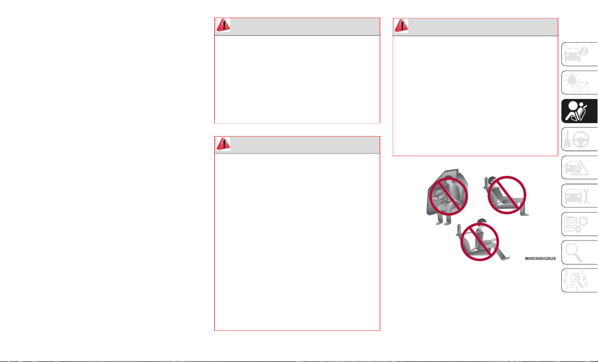
153
(Continued)
side Air Bags and also the seat belt preten-
sioner system when the passenger Air Bag
de
activation indicator light turns on.
This system shuts off the passenger front
an
d side Air Bags and seat belt pretensioner
system, so make sure the passenger Air Bag
deactivation indicator light turns on.
The air bag/seat belt pretensioner system
wa
rning light flashes and the passenger Air
Bag deactivation indicator light illuminates if
the sensors have a possible malfunction. If
this happens, the passenger front and side
Air Bags and seat belt pretensioner system
will not deploy.
NOTE:
If a passenger is seated as shown in the
fo
llowing figure the passenger occupant clas-
sification sensor cannot detect a passenger
s
i
tting on the passenger's seat correctly and
the deployment/non-deployment of the Air
Bags cannot be controlled as indicated in the
passenger Air Bag deactivation indicator
light on/off condition chart.
Improper Seating Positions
WARNING!
If a child restraint system, child, small
teenager or adult in the front passenger
seat is seated improperly, the occupant
may provide an output signal to the
occupant classification sensor that is
different from the occupant’s properly
seated weight input. This may result in
serious injury or death in a collision.
WARNING!
Ignoring the Air Bag Warning Light in
your instrument panel could mean you
won’t have the air bags to protect you in
a collision. If the light does not come on
as a bulb check when the ignition is first
turned on, stays on after you start the
vehicle, or if it comes on as you drive,
have an authorized dealer service the air
bag system immediately.
Placing an object on the floor under the
front passenger seat may prevent the
occupant classification sensor from
working properly, which may result in
serious injury or death in a collision. Do
not place any objects on the floor under
the front passenger seat.
If there is a fault present in the occupant
classification sensor, both the Indicator
Light and the Air Bag Warning Light will
illuminate to show that the Passenger
Advanced Front Air Bag is deactivated.
Should this occur, the Passenger
Advanced Front Air Bag will remain
deactivated until the fault is cleared.
This indicates that you should take the
vehicle to an authorized dealer for
service immediately.
WARNING! (Continued)
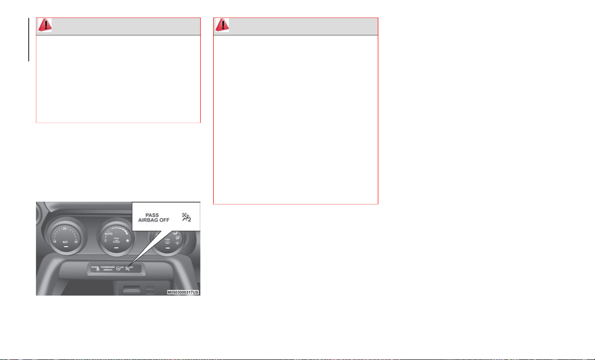
SAFETY
154
Passenger Air Bag Deactivation Indicator Lights
These indicator lights turn on to remind you
th
at the passenger front and side Air Bags
and seat belt pretensioner will or will not
deploy during a collision.
Passenger Air Bag Deactivated
NOTE:
The system requires about 10 seconds to
alternate between turning the passenger
front and side Air Bags and seat belt
pretensioner system on or off.
The passenger air bag deactivation indi-
cator light may turn on repeatedly if
lu
ggage or other items are put on the
passenger seat, or if the temperature of
the vehicle's interior changes suddenly.
The passenger air bag deactivation indi-
cator light may turn on for 10 seconds if
th
e electrostatic capacity on the passenger
seat changes.
The air bag/seat belt pretensioner system
warning light might turn on if the
passenger seat receives a severe impact.
If the passenger Air Bag deactivation indi-
cator light does not turn on after installing
a
child restraint system on the passenger
seat, first, reinstall your child restraint
system according to the procedure in this
Owner’s Manual. Then, if the passenger
Air Bag deactivation OFF indicator light
still does not turn on, contact an autho
-
rized dealer as soon as possible.
If the passenger Air Bag deactivation indi-
cator light turns on when an occupant is
se
ated directly in the passenger seat, have
the passenger readjust their posture by
sitting with their feet on the floor, and
then refastening the seat belt. If the
passenger Air Bag deactivation indicator
light remains turned on, slide the
passenger seat as far back as possible.
Contact an authorized dealer as soon as
possible.
WARNING!
Do not carry or hold any objects (e.g.,
backpacks, boxes, etc.) while seated in the
front passenger seat. Holding an object
may provide an output signal to the
occupant classification sensor that is
different than the occupant’s properly
seated weight input, which may result in
serious injury or death in a collision.
WARNING!
Never place a rear-facing child restraint
in front of an air bag. A deploying
passenger front air bag can cause death
or serious injury to a child 12 years or
younger, including a child in a
rear-facing child restraint.
Never install a rear-facing child restraint
in the front seat of a vehicle. Only use a
rear-facing child restraint in the rear
seat. If the vehicle does not have a rear
seat, do not transport a rear-facing child
restraint in that vehicle.
Children 12 years or younger should
always ride buckled up in a vehicle with
a rear seat.
155
(Continued)
(Continued)
Passenger Air Bag Deactivation Indicator Light
On/Off Condition Chart
If the passenger occupant classification
se
nsor is normal, the indicator light turns on
when the ignition is cycled on. The light
turns off after a few seconds. Then, the indi
-
cator light turns on or is off under the
fo
llowing conditions:
(*) The occupant classification sensor may not detect a child seated on the seat, in a child restraint system, or a junior seat depending on the child's
physical size and seated posture.
(**) If a smaller adult sits on the passenger seat, the sensors might detect the person as being a child depending on the person's physique.
If the passenger air bag deactivation indicator light does not turn on when the ignition is cycled ON and does not turn on as indicated in the passenger
ai
r bag deactivation indicator light on/off condition chart, do not allow an occupant to sit in the passenger seat and contact an authorized dealer as
soon as possible. The system may not work properly in an accident.
Condition Detected By The
Passenger Occupant
Classification System
Passenger Air Bag Deactivation
Ind
icator Light
Passenger Front And Side Air
Bags
Passenger Seat Belt
Pretensioner System
Empty (Not occupied) On Deactivated Deactivated
A child is seated in a child
re
straint system (*)
On Deactivated Deactivated
Adult (**) Off Ready Ready
WARNING!
Never place a rear-facing child restraint
in front of an air bag. A deploying
passenger front air bag can cause death
or serious injury to a child 12 years or
younger, including a child in a
rear-facing child restraint.
Never install a rear-facing child restraint
in the front seat of a vehicle. Only use a
rear-facing child restraint in the rear
seat. If the vehicle does not have a rear
seat, do not transport a rear-facing child
restraint in that vehicle.
WARNING! (Continued)
Children 12 years or younger should
always ride buckled up in a vehicle with
a rear seat.
WARNING! (Continued)

SAFETY
156
(Continued)
Maintaining Your Air Bag System
WARNING!
No objects should be placed over or near
the air bag on the instrument panel or
steering wheel because any such objects
could cause harm if the vehicle is in a
collision severe enough to cause the air
bag to inflate.
Do not put anything on or around the air
bag covers or attempt to open them
manually. You may damage the air bags
and you could be injured because the air
bags may no longer be functional. The
protective covers for the air bag cushions
are designed to open only when the air
bags are inflating.
Relying on the air bags alone could lead
to more severe injuries in a collision. The
air bags work with your seat belt to
restrain you properly. In some collisions,
air bags won’t deploy at all. Always wear
your seat belts even though you have air
bags.
WARNING!
Modifications to any part of the air bag
system could cause it to fail when you
need it. You could be injured if the air
bag system is not there to protect you.
Do not modify the components or wiring,
including adding any kind of badges or
stickers to the steering wheel hub trim
cover or the upper passenger side of the
instrument panel. Do not modify the
front bumper, vehicle body structure, or
add aftermarket side steps or running
boards.
It is dangerous to try to repair any part of
the air bag system yourself. Be sure to
tell anyone who works on your vehicle
that it has an air bag system.
Do not attempt to modify any part of your
air bag system. The air bag may inflate
accidentally or may not function properly
if modifications are made. Take your
vehicle to an authorized dealer for any air
bag system service. If your seat,
including your trim cover and cushion,
needs to be serviced in any way
(including removal or loosening/tight
-
ening of seat attachment bolts), take the
v
e
hicle to an authorized dealer. Only
manufacturer approved seat accessories
may be used. If it is necessary to modify
the air bag system for persons with
disabilities, contact an authorized
dealer.
WARNING! (Continued)

157
EVENT DATA RECORDER
(EDR)
This vehicle is equipped with an Event Data
Recorder (EDR).
The main purpose of an EDR is to record, in
ce
rtain crash or near crash-like situations, such
as an air bag deployment or hitting a road
obstacle, data that will assist in understanding
how a vehicle’s systems performed. The EDR is
designed to record data related to vehicle
dynamics and safety systems for a short period
of time, typically 30 seconds or less.
The EDR in this vehicle is designed to record
su
ch data as:
How various systems in your vehicle were
operating.
Whether or not the driver and passenger
safety belts were buckled/fastened.
How far (if at all) the driver was pushing
the accelerator and/or brake pedal.
How fast the vehicle was traveling.
This data can help provide a better under-
standing of the circumstances in which
cr
ashes and injuries occur.
NOTE:
EDR data are recorded by your vehicle only
if a non-trivial crash or near crash-like situ-
ation occurs; no data are recorded by the
E
D
R under normal driving conditions and
no personal data (e.g., name, gender, age,
and crash location) are recorded. However,
other parties, such as law enforcement,
could combine the EDR data with the type
of personally identifying data routinely
acquired during a crash investigation.
To read data recorded by an EDR, special
equipment is required, and access to the
vehicle or the EDR is needed. In addition
to the vehicle manufacturer, other parties,
such as law enforcement, that have the
special equipment, can read the informa
-
tion if they have access to the vehicle or
t
h
e EDR.
FCA US LLC will not disclose any of the data
re
corded in an EDR to a third party unless:
A written agreement from the vehicle
owner or the lessee is obtained.
Officially requested by the police or other
law enforcement authorities.
Used as a defense for FCA US LLC in a law
suit, claim, or arbitration.
Ordered by a judge or court.
However, if necessary, FCA US LLC will:
Use the data for research on FCA US LLC
vehicle performance, including safety.
Disclose the data or the summarized data
to a third party for research purposes
without disclosing vehicle or owner identi
-
fication information.
Recording Of Vehicle Data
This vehicle is equipped with a computer
wh
ich records the following main vehicle
data related to vehicle controls, operation,
and other driving conditions.
Recorded Data
Vehicle conditions such as engine speed
and vehicle speed.
Driving operation conditions such as
accelerator and brake pedals, and infor-
mation related to the environmental
circumstances while the vehicle is driven.

SAFETY
158
Malfunction diagnosis information from
each on-vehicle computer.
Information related to controls of other
on-vehicle computers.
The recorded data may vary depending on
th
e vehicle grade and optional equipment.
Voice and images are not recorded.
Data Handling
FCA US LLC and its subcontracting parties
ma
y obtain and use the recorded data for
vehicle malfunction diagnosis, research and
development, and quality improvement.
FCA US LLC will not disclose or provide any
of
the obtained data to a third party unless:
An agreement from the vehicle owner
(agreements from lessor and lessee for
leased vehicle) is obtained.
Officially requested by the police or other
law enforcement authorities.
For statistical processing by a research
institution, after processing the data so
that identification of the owner or the
vehicle is impossible.
CONSTANT MONITORING
The following components of the Air Bag
systems are monitored by a diagnostic
system:
Crash Sensors, And Diagnostic Module
(Sas Unit)
Front Air Bag Sensors
Air Bag Modules
Side Crash Sensors
Air Bag/Seat Belt Pretensioner System
Warning Light
Seat Belt Buckle Switch
Seat Belt Pretensioners
Related Wiring
With Passenger Occupant Classification
Sy
stem
Passenger Air Bag Deactivation Indicator
Light
Passenger Occupant Classification Sensor
Passenger Occupant Classification
Module — if equipped
The diagnostic module continuously moni-
tors the system's readiness. This begins
w
h
en the ignition is cycled on and continues
while the vehicle is being driven.
Enhanced Accident Response System
In the event of an impact, if the communica-
tion network remains intact, and the power
re
mains intact, depending on the nature of
the event, the Occupant Restraint Controller
(ORC) will determine whether to have the
Enhanced Accident Response System
perform the following functions:
Cut off fuel to the engine (if equipped)
Cut off battery power to the electric motor
(if equipped)
Flash hazard lights as long as the battery
has power
Turn on the interior lights, which remain
on as long as the battery has power or for
15
minutes from the intervention of the
En
hanced Accident Response System
Unlock the power door locks

159
Your vehicle may also be designed to perform
any of these other functions in response to
the Enhanced Accident Response System:
Turn off the Fuel Filter Heater, Turn off
the HVAC Blower Motor, Close the HVAC
Circulation Door
Cut off battery power to the:
Engine
Electric Motor (if equipped)
Electric power steering
Brake booster
Electric park brake
Automatic transmission gear selector
Horn
Front wiper
Headlamp washer pump
NOTE:
After an accident, remember to cycle the
ig
nition to the STOP (OFF/LOCK) position
and remove the key from the ignition switch
to avoid draining the battery. Carefully check
the vehicle for fuel leaks in the engine
compartment and on the ground near the
engine compartment and fuel tank before
resetting the system and starting the engine.
If there are no fuel leaks or damage to the
vehicle electrical devices (e.g. headlights)
after an accident, reset the system by
following the procedure described below. If
you have any doubt, contact an authorized
dealer.
Enhanced Accident Response System
Reset Procedure
In order to reset the Enhanced Accident
Response System functions after an event,
the ignition switch must be changed from
ignition START or ON/RUN to ignition off.
Carefully check the vehicle for fuel leaks in
the engine compartment and on the ground
near the engine compartment and fuel tank
before resetting the system and starting the
engine.

160
(Continued)
STARTING AND OPERATING
STARTING THE ENGINE
Starting The Engine
Before starting the engine, adjust the seat,
the interior rear view mirrors, the door
mirrors, and fasten the seat belt correctly.
Never press the accelerator pedal for starting
th
e engine.
Models Equipped With A Manual
Transmission
Proceed as follows:
1. Engage the parking brake and place the
g
ear selector in NEUTRAL.
2. Place the start button in the ACC mode.
3
. Fully depress the clutch pedal without
t
ouching the accelerator.
4. Place the start button in the ON mode,
p
ush and release it as soon as the engine
starts. If the engine does not start within
10 seconds, push the start button to OFF
mode and wait for 10-15 seconds before
repeating the starting procedure.
Models Equipped With An Automatic
Transmission
Proceed as follows:
1. Engage the parking brake and place the
g
ear selector to P (PARK) or N
(NEUTRAL).
2. Fully depress the brake pedal without
t
ouching the accelerator.
3. Place the start button in the ACC mode.
4
. Place the start button in the ON mode,
p
ush and release it as soon as the engine
starts. If the engine does not start within
10 seconds, push the start button to OFF
mode and wait for 10-15 seconds before
repeating the starting procedure.
Cold Weather Operation
Regarding Cold Start Disable
When the ambient temperature is extremely
lo
w, the engine may not crank even when the
engine starting procedure is performed. At
this time, the Cold Start Disable Indicator
light in the instrument cluster flashes.
However, this does not indicate a problem.
WARNING!
When leaving the vehicle, always remove
the key fob from the vehicle and lock
your vehicle.
Never leave children alone in a vehicle,
or with access to an unlocked vehicle.
Allowing children to be in a vehicle unat-
tended is dangerous for a number of
re
asons. A child or others could be seri-
ously or fatally injured. Children should
b
e
warned not to touch the parking
brake, brake pedal or the transmission
gear selector.
Do not leave the key fob in or near the
vehicle, or in a location accessible to
children, and do not leave the ignition of
a vehicle equipped with Advanced
Keyless Entry in the ACC or ON/RUN
mode. A child could operate power
windows, other controls, or move the
vehicle.
Do not leave children or animals inside
parked vehicles in hot weather. Interior
heat build-up may cause serious injury or
death.
WARNING! (Continued)
161
Perform the necessary procedures (see
“Warning lights And Messages” paragraph in
“Getting To Know Your Instrument Panel”
chapter).
Regarding Ice Breaker
When the ambient temperature is low, the
st
art of cranking may be delayed after engine
starting procedure is performed. At this time,
the Cold Start Disable Indicator light in the
instrument cluster illumintes. However, this
does not indicate a problem.
Refer to your authorized dealer regarding
ot
her related parts which are to be input such
as function name, operating scenario (condi
-
tion) of each function, indicator operation,
an
d user operation/procedure information.
Extended Park Starting
NOTE:
Extended Park condition occurs when the
ve
hicle has not been started or driven for at
least 30 days.
1. Install a battery charger or jumper cables
t
o the battery to ensure a full battery
charge during the crank cycle.
2. Place the ignition in the START mode
a
nd release it when the engine starts.
3. If the engine fails to start within 10
s
econds, place the ignition in the STOP
(OFF/LOCK) mode, wait five seconds to
allow the starter to cool, then repeat the
Extended Park Starting procedure.
4. If the engine fails to start after eight
a
ttempts, allow the starter to cool for at
least 10
minutes, then repeat the proce-
dure.
After Starting — Warming Up The Engine
Proceed as follows:
1. Travel slowly, letting the engine run at a
r
educed RPM, without accelerating
suddenly.
2. It is recommended to wait until the
d
igital engine coolant temperature indi-
cator starts moving before demanding
f
u
ll performance.
Stopping The Engine
Proceed as follows:
1. Park the car in a position that is not
d
angerous for oncoming traffic, if
equipped with manual transmission
place gear selector in FIRST (1st) or
REVERSE (R) gear, if equipped with
automatic transmission place the gear
selector to PARK (P).
2. Push and release the ignition button to
S
TOP the engine.
BRAKE SYSTEM
This vehicle has power-assisted brakes that
adjust automatically through normal use.
Should power-assist fail, you can stop by
applying greater force than normal to the
brake pedal. But the distance required to
stop will be greater than usual.
NOTE:
Always depress the brake pedal with the right
fo
ot. Applying the brakes with the unaccus-
tomed left foot could slow your reaction time
t
o
an emergency situation resulting in insuf-
ficient braking operation.
CAUTION!
To prevent damage to the starter, do not
crank continuously for more than 10 seconds
at a time. Wait 10 to 15 seconds before
trying again.

STARTING AND OPERATING
162
(Continued)
Do not drive with your foot held on the clutch
pedal or brake pedal, or hold the clutch
pedal depressed halfway unnecessarily.
Doing so could result in the following:
The clutch and brake parts will wear out
more quickly.
The brakes can overheat and adversely
affect brake performance.
Parking Brake
NOTE:
Driving with the parking brake on will cause
ex
cessive wear of the brake parts.
Setting the Parking Brake
Depress the brake pedal and then firmly pull
th
e parking brake lever fully upwards with
sufficient force to hold the vehicle in a
stationary position.
Releasing the Parking Brake
Depress the brake pedal and pull the parking
br
ake lever upwards, then press the release
button. While holding the button, lower the
parking brake lever all the way down to the
released position.
WARNING!
Riding the brakes can lead to brake
failure and possibly a collision. Driving
with your foot resting or riding on the
brake pedal can result in abnormally
high brake temperatures, excessive
lining wear, and possible brake damage.
You would not have your full braking
capacity in an emergency.
Driving a vehicle with the “Brake
Warning Light” on is dangerous. A signif-
icant decrease in braking performance or
v
e
hicle stability during braking may
occur. It will take you longer to stop the
vehicle or will make your vehicle harder
to control. You could have a collision.
Have the vehicle checked immediately.
CAUTION!
Wear shoes appropriate for driving in order
to avoid your shoe contacting the brake
pedal when depressing the accelerator
pedal.
WARNING!
Never leave children alone in a vehicle,
or with access to an unlocked vehicle.
Allowing children to be in a vehicle unat-
tended is dangerous for a number of
re
asons. A child or others could be seri-
ously or fatally injured. Children should
b
e
warned not to touch the park brake,
brake pedal or the gear selector.
Do not leave the key fob in or near the
vehicle or in a location accessible to chil-
dren. A child could operate power
w
i
ndows, other controls, or move the
vehicle.
Be sure the park brake is fully disen-
gaged before driving; failure to do so can
le
ad to brake failure and a collision.
Always fully apply the park brake when
leaving your vehicle, or it may roll and
cause damage or injury. Also be certain
to leave a manual transmission in
REVERSE (R) or FIRST (1st) gear.
Failure to do so may allow the vehicle to
roll and cause damage or injury.
WARNING! (Continued)
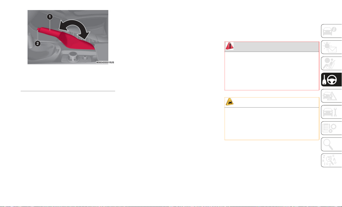
163
Parking Brake
Warning Light
The warning light turns on when the system
ha
s a malfunction. Refer to “Warning Lights
And Messages” in “Getting To Know Your
Instrument Panel” for further information.
Brake Pad Wear Indicator
When the disc brake pads become worn, the
bu
ilt-in wear indicators contact the rotors.
This causes a screeching noise to warn that
the pads should be replaced. When you hear
this noise contact your authorized dealer as
soon as possible.
Brake Assist
During emergency braking situations when it
is
necessary to depress the brake pedal with
greater force, the brake assist system
provides braking assistance, thus enhancing
braking performance. When the brake pedal
is depressed hard or depressed more quickly,
the brakes apply more firmly.
NOTE:
When the brake pedal is depressed hard or
depressed more quickly, the pedal will feel
softer but the brakes will apply more
firmly. This is a normal effect of the brake
assist operation and does not indicate a
malfunction.
When the brake pedal is depressed hard or
depressed more quickly, a motor/pump
operation noise may be heard. This is a
normal effect of the brake assist and does
not indicate a malfunction.
The brake assist equipment does not
supersede the functionality of the
vehicle's main braking system.
MANUAL TRANSMISSION —
IF EQUIPPED
Manual Transmission
1 — Parking Brake Lever
2 — Parking Brake Release Button
WARNING!
You or others could be injured if you leave
the vehicle unattended without having the
park brake fully applied. The park brake
should always be applied when the driver
is not in the vehicle, especially on an
incline.
CAUTION!
Never drive with your foot resting on the
clutch pedal, or attempt to hold the
vehicle on a hill with the clutch pedal
partially engaged, as this will cause
abnormal wear on the clutch.
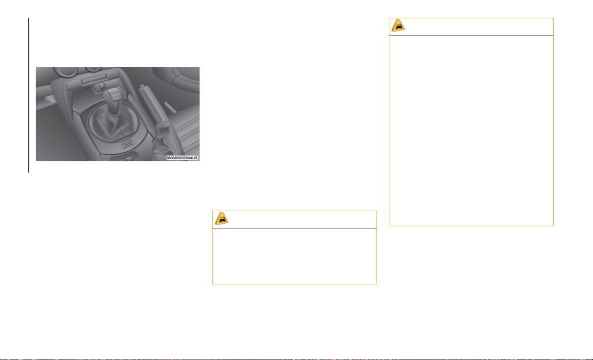
STARTING AND OPERATING
164
(Continued)
To engage the gears, press the clutch pedal
fully and put the gear selector into the
required position. The diagram for gear
engagement is shown on the knob.
Gear Selector
Depress the clutch pedal all the way down
wh
ile shifting, then release it slowly.
Your vehicle is equipped with a device to
pr
event shifting to REVERSE (R) by mistake.
Push the gear selector downward and shift to
REVERSE (R).
A natural driving posture can be achieved by
li
ghtly gripping the gear selector from the
side without having to rest your elbow on the
center console.
If shifting to REVERSE (R) is difficult, shift
ba
ck into neutral, release the clutch pedal,
and try again.
NOTE:
A certain amount of noise from the transmis-
sion is normal. This noise can be most
n
o
ticeable when the vehicle is idling in
NEUTRAL with the clutch engaged (clutch
pedal released), but it may also be heard
when driving. The noise may also be more
noticeable when the transmission is warm.
This noise is normal and is not an indication
of a problem with your clutch or transmis
-
sion.
With Parking Sensor System
When the gear selector is shifted to the
R
E
VERSE (R) position with the ignition
placed in the ON mode, the parking sensor
system is activated an audible sound is
heard.
AUTOMATIC
TRANSMISSION — IF
EQUIPPED
Shift Interlock
This vehicle is equipped with an interlock
system that holds the transmission gear
selector in PARK (P) unless the brakes are
CAUTION!
Keep your foot off the clutch pedal
except when shifting gears. Also, do not
use the clutch to hold the vehicle on an
hill or grade. Riding the clutch will cause
needless clutch wear and damage.
Do not apply any excessive lateral force
to the gear selector when changing from
fifth to fourth gear. This could lead to the
accidental selection of second gear,
which could result in damage to the
transmission.
Make sure the vehicle comes to a
complete stop before shifting to
REVERSE (R). Shifting to REVERSE (R)
while the vehicle is still moving may
damage the transmission.
Reverse can only be engaged when the
vehicle is completely stationary. With
the engine running, wait at least two
seconds with the clutch pedal fully
pressed before engaging reverse to
prevent damage to the gears.
CAUTION! (Continued)

165
(Continued)
applied. To shift the transmission out of
PARK (P), the ignition must be placed in the
ON/RUN mode (engine running or not) and
the brake pedal must be pressed.
The gear selector must be in PARK (P) or
NE
UTRAL (N) to operate the starter.
The transmission gear selector has PARK
(P
), REVERSE (R), NEUTRAL (N), DRIVE
(D), and MANUAL (M)(+/–) shift positions.
The transmission may be shifted freely from
RE
VERSE (R), to NEUTRAL (N), to DRIVE
(D), to MANUAL (M)(+/–).
WARNING!
It is dangerous to shift out of PARK or
NEUTRAL if the engine speed is higher
than idle speed. If your foot is not firmly
pressing the brake pedal, the vehicle
could accelerate quickly forward or in
reverse. You could lose control of the
vehicle and hit someone or something.
Only shift into gear when the engine is
idling normally and your foot is firmly
pressing the brake pedal.
Unintended movement of a vehicle could
injure those in or near the vehicle. As
with all vehicles, you should never exit a
vehicle while the engine is running.
Before exiting a vehicle, always apply the
park brake, shift the transmission into
PARK, and turn the ignition OFF. When
the ignition is in the OFF mode, the
transmission is locked in PARK,
securing the vehicle against unwanted
movement.
When leaving the vehicle, always make
sure the ignition is in the OFF mode,
remove the key fob from the vehicle, and
lock the vehicle.
Never leave children alone in a vehicle,
or with access to an unlocked vehicle.
Allowing children to be in a vehicle unat
-
tended is dangerous for a number of
re
asons. A child or others could be seri-
ously or fatally injured. Children should
b
e
warned not to touch the parking
brake, brake pedal or the transmission
gear selector.
Do not leave the key fob in or near the
vehicle (or in a location accessible to
children), and do not leave the ignition
in the ACC or ON/RUN mode. A child
could operate power windows, other
controls, or move the vehicle.
WARNING! (Continued)
CAUTION!
Damage to the transmission may occur if
the following precautions are not observed:
Shift into or out of PARK or REVERSE
only after the vehicle has come to a
complete stop.
Do not shift between PARK, REVERSE,
NEUTRAL, or DRIVE when the engine is
above idle speed.
Before shifting into any gear, make sure
your foot is firmly pressing the brake
pedal.
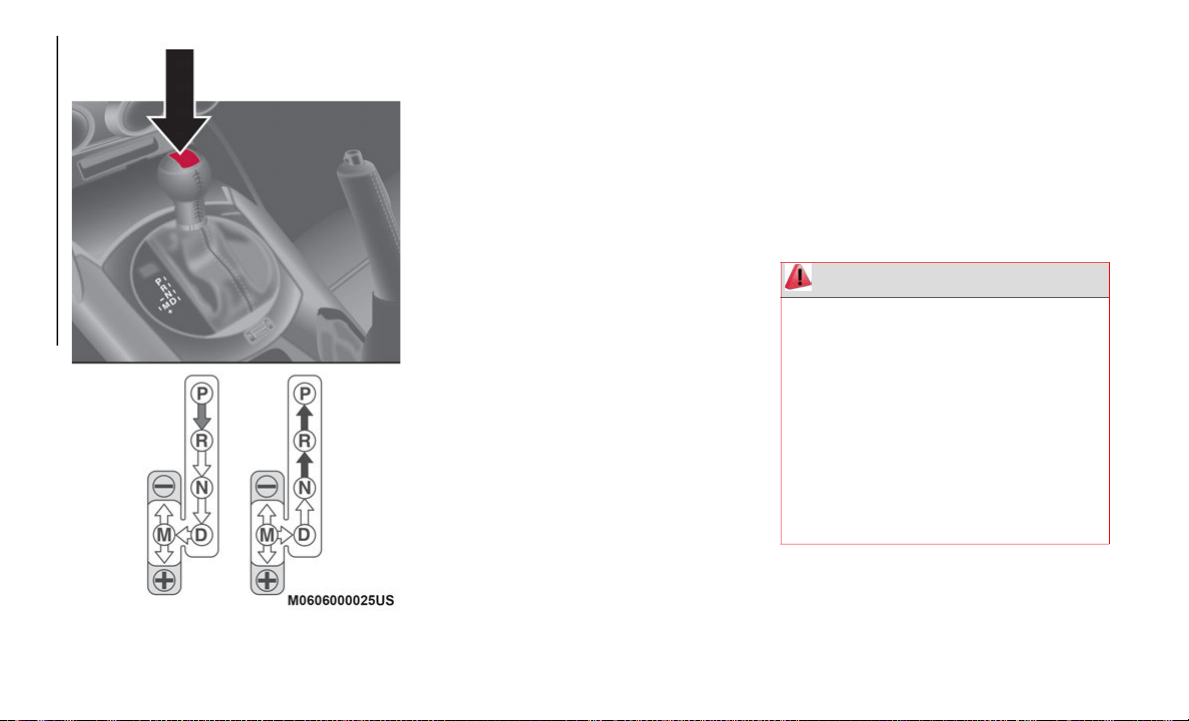
STARTING AND OPERATING
166
(Continued)
Gear Selector And Pattern
NOTE:
Even if you intend to use the automatic
tr
ansmission functions as a traditional auto-
matic, you should also be aware that you can
i
n
advertently shift into manual shift mode
and an inappropriate gear may be retained as
the vehicle speed increases. If you notice the
engine speed going higher or hear the engine
racing, confirm you have not accidentally
slipped into manual shift mode (refer to
“Manual Shift Mode” paragraph in this
section).
Shift Position Indication
The gear selector position (PRNDM) is illu-
minated when the ignition is placed in the
ON
mode.
NOTE:
If one of the following actions is performed,
t
h
e gear selector position is displayed for five
minutes even if the ignition is placed in a
mode other than ON.
The ignition is placed in the OFF mode.
The driver's door is opened.
Gear Position Indication
In MANUAL (M) shift mode, the “M” of the
sh
ift position indication illuminates and the
number of the selected gear is displayed.
Gear Selector Positions
PARK (P)
PARK (P) locks the transmission and
pr
events the driveshaft from rotating.
WARNING!
Never use the PARK position as a substi-
tute for the park brake. Always apply the
pa
rk brake fully when parked to guard
against vehicle movement and possible
injury or damage.
Your vehicle could move and injure you
and others if it is not in PARK. Check by
trying to move the gear selector out of
PARK with the brake pedal released.
Make sure the transmission is in PARK
before exiting the vehicle.

167
(Continued)
NOTE:
Shifting into PARK (P), NEUTRAL (N) or
REVERSE (R) while the vehicle is moving
can damage your transmission.
Shifting into DRIVE (D) or REVERSE (R)
when the engine is running faster than idle
can damage the transmission.
It is dangerous to shift out of PARK or
NEUTRAL if the engine speed is higher
than idle speed. If your foot is not firmly
pressing the brake pedal, the vehicle
could accelerate quickly forward or in
reverse. You could lose control of the
vehicle and hit someone or something.
Only shift into gear when the engine is
idling normally and your foot is firmly
pressing the brake pedal.
Unintended movement of a vehicle could
injure those in or near the vehicle. As
with all vehicles, you should never exit a
vehicle while the engine is running.
Before exiting a vehicle, always come to
a complete stop, then apply the park
brake, shift the transmission into PARK,
turn the ignition OFF, and remove the
key fob. When the ignition is in the
LOCK/OFF (key removal) position (or,
with pushbutton start, when the ignition
is in the OFF mode), the transmission is
locked in PARK, securing the vehicle
against unwanted movement.
WARNING! (Continued)
When leaving the vehicle, always make
sure the ignition is in the OFF mode,
remove the key fob from the vehicle, and
lock the vehicle.
Never leave children alone in a vehicle,
or with access to an unlocked vehicle.
Allowing children to be in a vehicle unat
-
tended is dangerous for a number of
re
asons. A child or others could be seri-
ously or fatally injured. Children should
b
e
warned not to touch the park brake,
brake pedal or the transmission gear
selector.
Do not leave the key fob in or near the
vehicle (or in a location accessible to
children), and do not leave the ignition
(in a vehicle equipped with pushbutton
start) in the ON/RUN mode. A child
could operate power windows, other
controls, or move the vehicle.
WARNING! (Continued)
CAUTION!
Before moving the transmission gear
selector out of PARK, you must turn the
ignition to the ON/RUN mode, and also
press the brake pedal. Otherwise,
damage to the gear selector could result.
DO NOT race the engine when shifting
from PARK or NEUTRAL into another
gear range, as this can damage the drive
-
train.

STARTING AND OPERATING
168
REVERSE (R)
This range is for moving the vehicle back-
ward. Shift into REVERSE only after the
ve
hicle has come to a complete stop.
With Parking Sensor system:
when the gear
selector is shifted to the REVERSE (R) posi-
tion with the ignition placed in the ON mode,
t
h
e parking sensor system is activated and
an audible sound is heard.
NEUTRAL (N)
In NEUTRAL (N), the wheels and transmis-
sion are not locked. The vehicle will roll
fr
eely even on the slightest incline unless the
parking brake or brakes are applied.
NOTE:
Do not shift into NEUTRAL (N) when driving
th
e vehicle. Doing so will damage the trans-
mission. Press the parking brake or depress
t
h
e brake pedal before moving the gear
selector from NEUTRAL (N) to prevent the
vehicle from moving unexpectedly.
DRIVE (D)
DRIVE (D) is the normal driving position.
Fr
om a stop, the transmission will automati-
cally shift through all available gears.
MANUAL (M)
MANUAL (M) is the manual shift mode posi-
tion. Gears can be shifted up or down by
o
p
erating the gear selector. (Refer to
“Manual Shift Mode” paragraph in this
section).
Active Adaptive Shift (AAS)
Active Adaptive Shift (AAS) automatically
controls the transmission shift points to best
suit the road conditions and driver input.
This improves driving feel.
The transmission may switch to AAS mode
wh
en driving up and down slopes, cornering,
driving at high elevations, or depressing the
accelerator pedal quickly while the gear
selector is in the DRIVE (D) position.
Depending on the road and driving conditions/
ve
hicle operations, gear shifting could be
delayed or not occur, however, this does not
indicate a problem because the AAS mode
will maintain the optimum gear position.
Shift-Lock System
The shift-lock system prevents shifting out of
PARK (P) unless the brake pedal is
depressed.
To shift from PARK (P):
1. Depress and hold the brake pedal.
2
. Turn the ignition to the ON/RUN mode.
3
. Press and hold the lock-release button on
t
he gear selector.
4. Move the gear selector.
W
hen the ignition is in the ACC or OFF mode, the
ge
ar selector cannot be shifted from PARK (P).
The ignition cannot be placed in the OFF mode
if
the gear selector is not in PARK (P).
WARNING!
Do not coast in NEUTRAL and never turn
off the ignition to coast down a hill. These
are unsafe practices that limit your
response to changing traffic or road
conditions. You might lose control of the
vehicle and have a collision.
WARNING!
Do not downshift for additional engine
braking on a slippery surface. The drive
wheels could lose their grip and the
vehicle could skid, causing a collision or
personal injury.
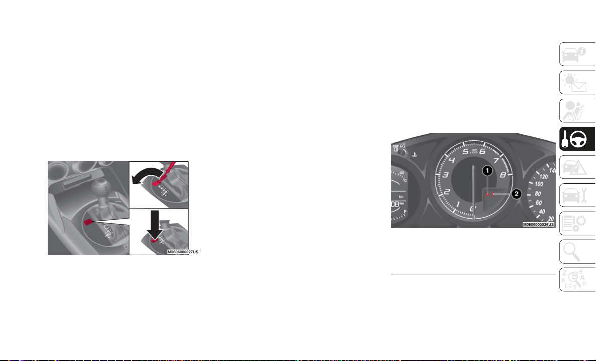
169
Shift Lock Override
If the gear selector will not move from PARK
(P) using the proper shift procedure,
continue to press the brake pedal and
proceed as follows:
1. Remove the shift lock override cover
u
sing a cloth wrapped flat head screw-
driver.
2. I
nsert a screwdriver or similar tool into
t
he Override Access Hole, and push the
override button down.
Shift Lock Override Access Hole
3. P
ush and hold the lock release button on
t
he gear selector and move the gear
selector.
4. Take the vehicle to an authorized dealer.
Manual Shift Mode
The manual shift mode gives you the feel of
driving a manual transmission vehicle by
allowing you to operate the gear selector
manually.
This allows you to control engine RPM and
to
rque to the drive wheels much like a
manual transmission when more control is
desired.
To change to MANUAL (M) shift mode, shift
th
e gear selector from DRIVE (D) to MANUAL
(M). To return to automatic shift mode, shift
the gear selector from MANUAL (M) to
DRIVE (D).
You can shift between DRIVE (D) and
MA
NUAL (M) mode at any time, without
taking your foot off the accelerator.
NOTE:
If you change to manual shift mode when
the vehicle is stopped, the gear will shift to
M1.
If you change to manual shift mode while
the vehicle is moving it will remain in the
current gear until a manual shift request is
made.
Indicators
Manual Shift Mode Indication
In manual shift mode, the “M” of the shift
p
o
sition indication in the instrument panel
illuminates.
Gear Position Indication
The numeral for the selected gear illumi-
nates.
Instrument Panel
1 — Manual Shift Mode Indication
2 — Gear Position Indication

STARTING AND OPERATING
170
Manually Shifting Up/Down
To shift up t
o a higher gear, tap the gear
selector rearward once (or tap the [+] shift
paddle on the steering wheel, if equipped).
To shift down t
o a lower gear, tap the gear
selector forward once (or tap the [-] shift
paddle on the steering wheel, if equipped).
NOTE:
If a requested downshift would cause the
engine to over-speed, that shift will not
occur.
The system will ignore attempts to upshift
at too low of a vehicle speed.
Do not drive the vehicle with the tachom-
eter needle in the red zone while in
ma
nual shift mode.
During deceleration, the transmission may
automatically shift down depending on
vehicle speed.
You can start out, from a stop, in first or
second gear. Tapping the gear selector
rearward (+) (at a stop) will allow starting
in second gear. Starting out in second gear
can be helpful in snowy or icy conditions.
Paddle Mode — If Equipped
Tapping one of the steering wheel-mounted
shift paddles (+/-), if equipped, while the
gear selector is in DRIVE (D), will activate
Paddle Mode (a temporary manual mode).
The current gear will be displayed in the
instrument cluster, with the "M" also illumi
-
nated. The transmission will revert back to
n
o
rmal operation (if the gear selector
remains in DRIVE) after a period of time,
depending on accelerator pedal activity.
NOTE:
Because Paddle mode is only temporary, use
of
the MANUAL (M) position is recom-
mended if you need to drive the vehicle in a
p
a
rticular gear for long periods.
Driving Tips
Overtaking
For extra power when passing another
ve
hicle or climbing steep grades, press the
accelerator fully. The transmission will shift
to a lower gear, depending on vehicle speed.
NOTE:
The accelerator pedal may initially feel
heavy as it is being pressed, then feel
lighter as it is pressed further. This change
in pedal force controls whether or not kick
-
down should be performed.
While the gear selector is in the MANUAL
(M) position and the Dynamic Stability
Control (DSC) is turned off, manual shift
mode does not switch to automatic shift
mode even if the accelerator pedal is
completely pressed. Tap the gear selector
forward or rearward to select the appro
-
priate gear.
Climbing steep grades from a stop
To climb a steep grade from a stopped posi-
tion:
1. P
ress the brake pedal.
2
. Shift to DRIVE (D) or M1, depending on
t
he load weight and grade steepness.
3. Release the brake pedal while gradually
a
ccelerating.
Descending steep grades
When descending a steep grade, shift to
lo
wer gears, depending on load weight and
grade steepness.
Descend slowly, using the brakes only occa-
sionally to prevent them from overheating.
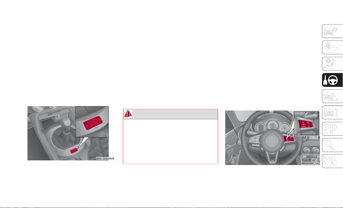
171
SPORT MODE — IF
EQUIPPED
The SPORT mode increases steering feed-
back to the driver with slight increase in
ef
fort and changes the transmission shift
schedules for more aggressive shifting. This
driving mode is useful while driving on twisty
roads where more steering precision is
desired in spirited cornering.
To activate SPORT mode, toggle the SPORT
Mo
de button forward and hold for approxi-
mately two seconds. You will see “Sport”
i
l
luminate in the Instrument Panel cluster.
SPORT Button
SPEED CONTROL
Speed Control
This is an electronically controlled driving
assistance feature that allows the desired
vehicle speed to be maintained, without
having to press the accelerator pedal.
This feature can be used at a speed above
25
mph (40 km/h) on long stretches of dry,
st
raight roads with few variations, such as
highways.
It is therefore not recommended to use this
fe
ature on city roads with traffic, or in areas
where the vehicle will stop frequently.
Activation / Deactivation
NOTE:
When the ignition is placed in the OFF posi-
tion, the system status before it was turned
o
f
f is stored. For example, if the ignition is
placed in the OFF position while the Speed
Control is operating, the system will be oper
-
able when the ignition is ON the next time.
Activating Speed Control
Push the ON button located on the right side
o
f
the steering wheel with the other Speed
Control buttons. The warning light (amber) in
the instrument cluster display will illumi
-
nate.
Speed Control Buttons
WARNING!
Speed Control can be dangerous where the
system cannot maintain a constant speed.
Your vehicle could go too fast for the
conditions, and you could lose control and
have an accident. Do not use Speed
Control in heavy traffic or on roads that are
winding, icy, snow-covered or slippery.

STARTING AND OPERATING
172
Deactivating Speed Control
Push the OFF/CAN button. The warning
light (amber) in the instrument cluster
di
splay turns off.
When A Speed Has Been Set:
the warning
light (green) in the instrument cluster
di
splay is illuminated, push and hold the
OFF/CAN button or push the OFF/CAN
button twice to deactivate.
When A Speed Has Not Been Set:
the
warning light (amber) in the instrument
cluster display is illuminated, push the OFF/
CAN button to deactivate.
Setting A Desired Speed
Proceed as follows:
1. Activate the Speed Control device by
p
ushing the ON button. The cruise
warning light (amber) illuminates.
2. Accelerate to the desired speed, which
m
ust be more than 25 mph (40 km/h).
3. S
et the Speed Control by pushing the
S
ET (-) button at the desired speed. The
Speed Control is set at the moment the
SET (-) button is pushed. Release the
accelerator pedal simultaneously. The
warning light (green) illuminates.
NOTE:
The Speed Control setting cannot be
p
e
rformed under the following conditions:
Automatic Transmission: the gear selector
is in the PARK or NEUTRAL position.
Manual Transmission: the gear selector is
in the NEUTRAL position or when the
clutch is disengaged (clutch is
depressed).
The parking brake is applied.
Release the SET (-) button at the desired
sp
eed, otherwise the speed will continue
decreasing while the SET (-) button is
pushed and held (except when the acceler
-
ator pedal is depressed).
NOTE:
Release the SET (-) button at the desired
speed, otherwise the speed will continue
decreasing while the SET (-) button is
pushed and held (except when the accel
-
erator pedal is depressed).
On a steep grade, the vehicle may momen-
tarily slow down while ascending, or speed
up
while descending.
The Speed Control will cancel if the
vehicle speed decreases below 16 mph
(2
5 km/h) when climbing a steep incline.
The Speed Control may cancel at about
9 mph (15 km/h) below the preset speed
su
ch as when climbing a long, steep
incline.
The vehicle’s set speed is displayed in the
in
strument cluster display.
WARNING!
Leaving the Speed Control system on when
not in use is dangerous. You could
accidentally set the system or cause it to
go faster than you want. You could lose
control and have an accident. Always leave
the system off when you are not using it.

173
Increasing Speed
To increase speed using the Speed Control
buttons:
Push the RES (+) button and hold it, your
vehicle will accelerate. Release the button
at the desired speed.
Push the RES (+) button and release it
immediately, to adjust the set speed.
Multiple pushes of the button will increase
the set speed according to the number of
times it is pushed.
Increasing speed with a single RES (+) button
op
eration:
If the instrument cluster display for
vehicle speed is indicated in mph: speed
will increase in 1
mph increments.
If the instrument cluster display for
vehicle speed is indicated in km/h: speed
will increase in 1
km/h increments.
To increase speed using accelerator pedal:
Press the accelerator pedal to accelerate
to the desired speed.
Push the SET (-) button and release it
immediately. This new set speed will be
saved.
NOTE:
Accelerate the vehicle to speed up tempo-
rarily with the accelerator pedal when the
S
p
eed Control is on. Increasing the speed
will not interfere with, or change the set
speed. Take your foot off the accelerator to
return to the set speed.
Decreasing Speed
To decrease speed using the Speed Control
buttons:
Push the SET (-) button and hold it, the
vehicle will gradually slow down. Release
the button at the desired speed.
Push the SET (-) button and release it
immediately to adjust the set speed.
Multiple button pushes will decrease the
set speed according to the number of
times it is pushed.
Decreasing speed with a single SET (-) button
op
eration:
If the instrument cluster display for
vehicle speed is indicated in mph: the
speed will decrease in 1
mph increments.
If the instrument cluster display for
vehicle speed is indicated in km/h: the
speed will decrease in 1
km/h increments.
Resume Speed
If any other method besides the OFF/CAN
button was used to cancel cruising speed
(such as applying the brake pedal or pressing
in the clutch pedal) and the system is still
activated, the most recent set speed will
automatically resume when the RES (+)
button is pushed.
If the vehicle speed is below 16 mph
(2
5 km/h), increase the vehicle speed up to
25
mph (40 km/h) or more and then push
th
e RES (+) button.
Temporarily Canceling The System
WARNING!
Leaving the Speed Control system on when
not in use is dangerous. You could
accidentally set the system or cause it to
go faster than you want. You could lose
control and have an accident. Always leave
the system OFF when you are not using it.
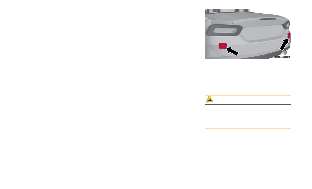
STARTING AND OPERATING
174
To temporarily cancel the system, use one of
these methods:
Slightly press the brake pedal.
Press the clutch pedal (if equipped with a
manual transmission).
Push OFF/CAN button.
If the RES (+) button is pushed when the
ve
hicle speed is 25 mph (40 km/h) or
hi
gher, the system reverts to the previously
set speed.
NOTE:
If any of the following conditions occur, the
Sp
eed Control system is temporarily
canceled:
The parking brake is applied.
Automatic Transmission: the gear selector
is in the PARK or NEUTRAL position.
Manual Transmission: the gear selector is
in the NEUTRAL position.
Automatic Transmission: the Speed Control
cannot be canceled while driving in
manual mode (gear selector shifted from D
to M position). Therefore, engine braking
will not be applied even if the transmis
-
sion is shifted down to a lower gear. If
de
celeration is required, lower the set
speed or press the brake pedal.
When the Speed Control system is tempo-
rarily canceled, the speed cannot be reset.
RADAR SENSORS — IF
EQUIPPED
Rear Radar Sensors
The following systems use the rear radar
sensors:
Blind Spot Monitoring (BSM) System
Rear Cross Traffic Alert (RCTA)
The radar sensors function by detecting the
ra
dio waves reflected off of a vehicle
approaching from the rear, or an obstruction,
sent from the radar sensor.
The radar sensors are installed inside the
re
ar bumper, one each on the left and right
sides.
Radar Sensor Locations
Always keep the surface of the rear bumper
n
e
ar the radar sensors clean so that the radar
sensors operate normally. Also, do not apply
items such as stickers.
The detection ability of the radar sensors has
li
mitations. In the following cases, the detec-
tion ability may be decreased, and the
s
y
stem may not operate normally:
The rear bumper near the radar sensors
has been damaged.
CAUTION!
If the rear bumper receives a severe
impact, the system may no longer operate
normally. Stop the system immediately
and contact an authorized dealer.

175
Snow, ice or mud has adhered to the radar
sensors on the rear bumper.
Operating in weather conditions such as
rain, snow and fog.
NOTE:
Under the following conditions, the radar
s
e
nsors cannot detect objects or it may be
difficult to detect them:
Stationary objects on a road or a road side
such as small, two-wheeled vehicles, bicy-
cles, pedestrians, animals, and shopping
c
a
rts.
Vehicle shapes which do not reflect radar
waves well such as empty trailers with a
low vehicle height and sports cars.
Vehicles are shipped with the direction of the
ra
dar sensors adjusted for each vehicle to a
loaded vehicle condition so that the radar
sensors detect approaching vehicles
correctly. If the direction of the radar sensors
has changed, contact an authorized dealer.
The radar sensors are regulated by the rele-
vant radio wave laws of the country in which
t
h
e vehicle is driven. If the vehicle is driven
abroad, authorization from the country in
which the vehicle is driven may be required.
NOTE:
For repairs or replacement of the radar
sensors, bumper repairs, paint work, or
replacement near the radar sensors,
consult an authorized dealer.
Turn off the radar system when pulling a
trailer or while an accessory, such as a
bicycle carrier, is installed to the rear of
the vehicle. Otherwise, the radio waves
emitted by the radar will be blocked
causing the system to not operate
normally.
REAR PARK ASSIST — IF
EQUIPPED
Rear Park Assist
WARNING!
Do not rely completely on the parking
sensor system and be sure to confirm the
safety around your vehicle visually when
driving. This system can assist the driver in
operating the vehicle in the forward and
backward directions while parking. The
detection ranges of the sensors are limited,
therefore, driving the vehicle while relying
only on the system may cause an accident.
Always confirm the safety around your
vehicle visually when driving.
Parking and other potentially dangerous
maneuvers are, however, always the
driver’s responsibility. When performing
these operations, always make sure that
there are no other people (especially
children) or animals on the route you
want to drive into. The parking sensors
are an aid for the driver, but the driver
must never allow their attention to lapse
during potentially dangerous maneuvers,
even those executed at low speeds.
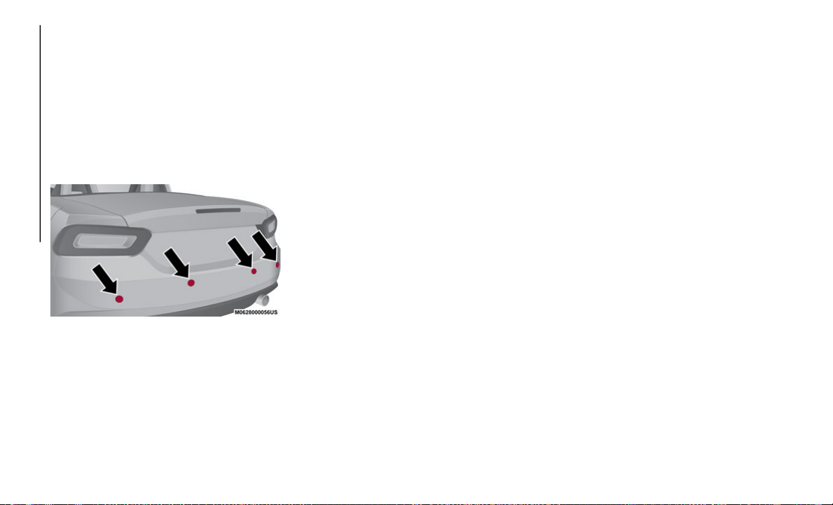
STARTING AND OPERATING
176
The Rear Park Assist System uses four ultra-
sonic sensors (two rear sensors and two rear
co
rner sensors) to detect obstructions around
the vehicle while parking the vehicle in a
garage, or during parallel parking when the
gear selector is in REVERSE.
The system is equipped with an assist device
to
notify the driver of the approximate
distance from the vehicle to the surrounding
obstruction using a audible alert.
Parking Sensor Locations
NOTE:
Do not install any accessories within the
detection ranges of the sensors. It may
affect the system operation.
Depending on the type of obstruction and
the surrounding conditions, the detection
range of a sensor may narrow, or the sensors
may not be able to detect obstructions.
The system may not operate normally
under the following conditions:
Mud, ice, or snow adhered to the sensor
area (operation will return to normal when
removed).
The sensor area is frozen (operation will
return to normal when the ice is thawed).
The sensor is covered by a hand or exces-
sive force has been applied to the bumper.
The vehicle is on a steep incline.
Under extremely hot or cold weather
conditions.
The vehicle is driven on bumps, inclines,
gravel, or grass covered roads.
Anything which generates ultrasound is
near the vehicle, such as another vehicle's
horn, the engine sound of a motorcycle,
the air brakes of a large-sized vehicle, or
another vehicle's sensors.
The vehicle is driven in heavy rain or in
road conditions causing water splash.
A antenna for a radio transmitter is
installed to the vehicle.
The vehicle is moving towards a tall or
square curbstone.
An obstruction is too close to the sensor.
Obstructions under the bumper may not
be detected. Obstructions that are lower
than the bumper or thin which may have
been initially detected but are no longer
detected as the vehicle approaches more
closely.
Always have the system inspected by an
authorized dealer if any force is applied to
the bumpers, even in a minor accident. If
the sensors have been repositioned in any
way, they cannot detect obstructions.
The system may have a malfunction if the
audible signal does not operate. Contact
an authorized dealer.
The beeper which indicates a system
malfunction may not be heard if the
ambient temperature is extremely cold, or
mud, ice, or snow adheres to the sensor
area. Remove any foreign material from
the sensor area.
When installing a trailer hitch, contact an
authorized dealer.

177
NOTE:
The following types of obstructions may not
be
detected:
Thin objects such as wire or rope.
Things which absorb sonic waves easily
such as rain or snow.
Angular shaped objects.
Very tall objects, and those which are wide
at the top.
Small, short objects.
Sensor Detection Range
The sensors detect obstructions within the
following range:
Lateral Detection Range: 22 inches (55 cm)
Rear Detection Range: 59 inches (150 cm)
System Operation
The system is operational when the ignition
is placed in the ON position, and the gear
selector is shifted to REVERSE. When an
audible signal sounds, the system is enabled
for use.
Parking Sensor Audible Alert
The audible alert will sound while the system
is operating according to the following chart:
(*) The rate at which the intermittent audible
alert increases as the vehicle approaches the
obstruction.
CAUTION!
Only have repairs on the bumper in the
area of the sensors carried out by an
authorized dealer. Repairs on the
bumper that are not carried out properly
may compromise the operation of the
parking sensors.
Only have the bumpers repainted or any
retouches to the paint work in the area of
the sensors carried out by an authorized
dealer. Incorrect paint application could
affect the operation of the parking
sensors.
Rear Sensor
Distance
Detection
Area
Distance
Betw
een
Vehicle And
Obstruction
Audible
Aler
t (*)
Farthest
distance
Approx. 59 -
23 inches
(1
50 cm -
60 cm)
Slow
in
termittent
sound
Far distance Approx. 23 -
17
inches
(6
0 - 45 cm)
Medium
in
termittent
sound
Middle
di
stance
Approx. 17 -
13 inches
(4
5 - 35 cm)
Fast
in
termittent
sound
Close
di
stance
Within
approx.
13
inches
(3
5 cm)
Continuous
so
und
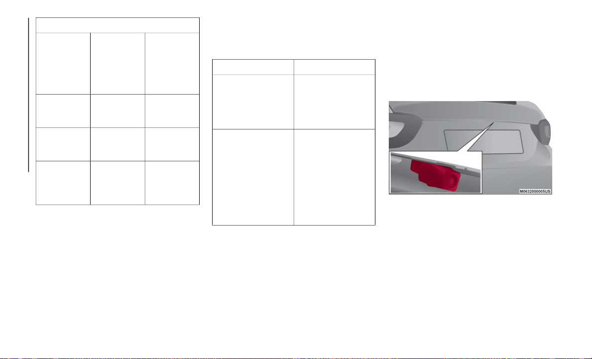
STARTING AND OPERATING
178
(**) The rate at which the intermittent audible
alert increases as the vehicle approaches the
obstruction.
NOTE:
If an obstruction is detected in a zone for six
se
conds or more, the audible alert stops,
unless the obstruction is within the close
distance zone. If the same obstruction is
detected in another zone, the corresponding
audible alert is heard.
When A Warning Alert Is Activated
The system notifies the driver of an obstacle
by activating the audible alert.
(*) The number of times the audible alert is
heard changes depending on the malfunction
location.
PARKVIEW REAR BACK UP
CAMERA
Operation
The camera is located on the trunk lid, above
the license plate.
Rear Camera Location
Changing The Display To Rear View Camera
Mo
de:
Place the gear selector in the REVERSE posi-
tion, after the ignition is placed in the ON
p
o
sition, to switch the display to rear-view
camera mode.
Rear Corner Sensor
Distance
Dete
ction
Area
Distance
Between
Vehicle And
Obstruction
Audible
Aler
t (**)
Far distance Approx. 22 -
14 inches
(5
5 - 38 cm)
Medium
in
termittent
sound
Middle
di
stance
Approx. 14 -
9.8 inches
(3
8 - 25 cm)
Fast
in
termittent
sound
Close
di
stance
Within
approx.
9.8
inches
(2
5 cm)
Continuous
so
und
Beep How To Check
The audible alert is
not heard.
The system may
ha
ve a malfunction.
Contact an
authorized dealer as
soon as possible.
When the ignition is
pl
aced in the ON
position, or if the
parking sensor
detects a problem
while driving, an
intermittent audible
alert is heard one to
four times (*).
Remove any foreign
ma
terial from the
sensor area. If the
system continues to
sound the audible
alert, contact an
authorized dealer as
soon as possible.
179
NOTE:
When the gear selector is moved from the
REVERSE position and put in any other
position, the screen returns to the previous
display mode.
When parking in REVERSE, take care over
obstacles that may be above or under the
camera’s display range.
When the display is cold, the images could
be more blurred than usual, making it
difficult to check the conditions of the
area around the vehicle. Always use
extreme caution and verify the real condi
-
tions of the area behind the vehicle with
yo
ur own eyes.
If water, snow, or mud is deposited on the
camera lens, clean it with a soft cloth. If
this does not clean it, use a mild deter
-
gent.
If the camera is subjected to abrupt
temperature changes (from hot to cold or
vice versa), the rear-view monitor may not
work properly.
When replacing tires, contact an autho-
rized dealer. Replacing the tires can cause
th
e guide lines that appear on the display
to be misaligned.
WARNING!
Always use extreme caution and verify
the real conditions of the area behind the
vehicle. Backing up while looking only at
the screen is dangerous and can lead to
an accident or collision with an object.
The rear-view monitor is simply a system
to aid reversing. The view on the display
can show a situation that differs from the
real one.
Do not use the rear-view monitor under
the following conditions:
Roads covered in ice or snow.
When snow chains are mounted or
the temporary space saver spare
wheel is fitted.
The rear trunk is not completely
closed.
The vehicle is on a sloping road.
Using the rear-view monitor under the
conditions listed above is dangerous and
can cause damage to persons and/or the
vehicle.
CAUTION!
Do not apply excessive force to the
camera. You could alter the position and
angle of the camera. Do not disas
-
semble, modify or remove it as this could
co
mpromise the seal.
The camera’s cover is made of plastic.
Do not apply degreasers, organic
solvents, wax or glass polish to the
camera’s cover. If some substance ends
up on the cover, clean it off immediately
with a soft cloth.
Do not rub the cover too much, nor
polish it with abrasive compounds or
hard brushes. The cover could be
damaged and create image problems.
If the vehicle has been involved in a
frontal, lateral or rear collision, the rear
parking camera’s alignment (location or
installation angle) may have been
altered. Contact an authorized dealer.
If the display shows "no video signal",
there may be a problem with the camera.
Contact an authorized dealer.
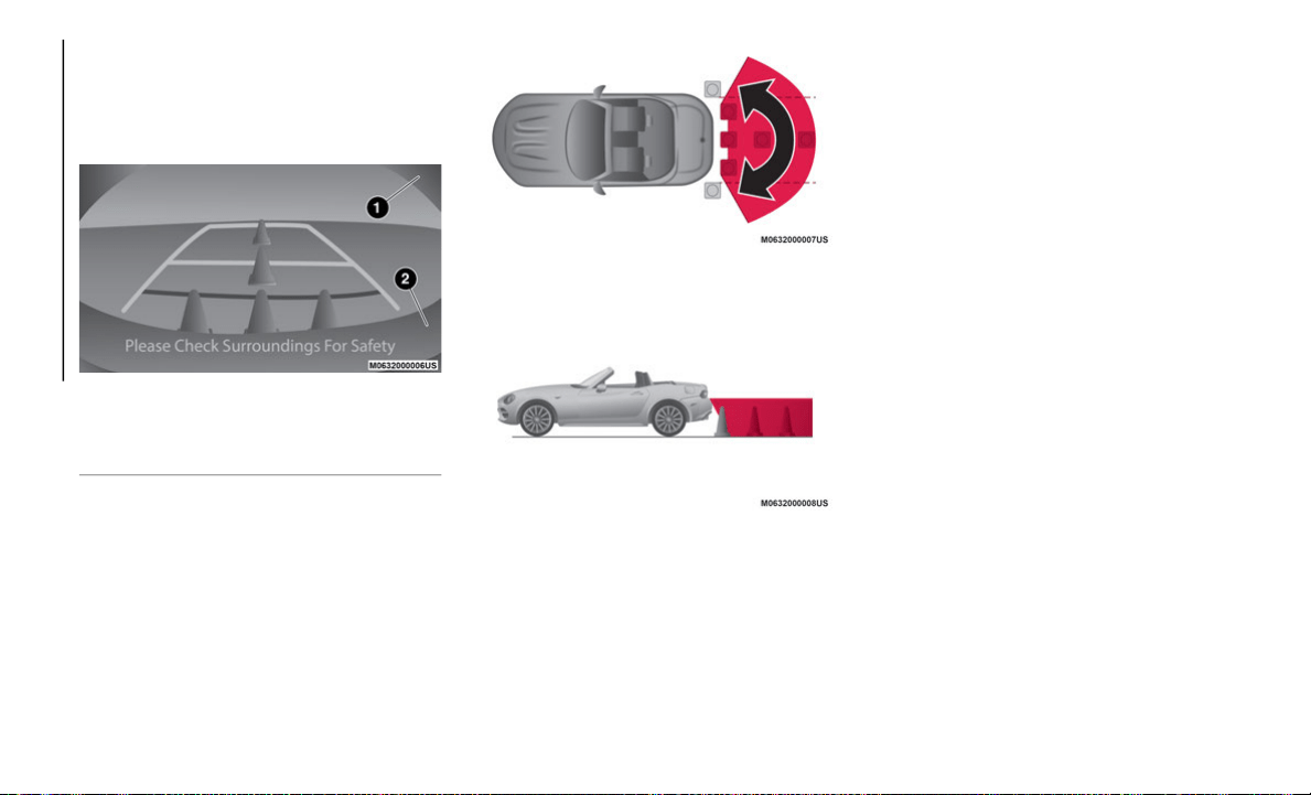
STARTING AND OPERATING
180
Display
NOTE:
The images on the display can show a situa-
tion that differs from the actual view.
Camera View
The field of view varies depending on the
ve
hicle and the road conditions. The field of
view is limited. Objects below the bumper or
around its sides may not be displayed.
Camera Field Of View
Camera Field Of View
The distance displayed by the camera view
d
i
ffers from the actual view, as the rear
parking camera is equipped with a special
lens.
The camera could capture any non-standard
ac
cessories installed on the vehicle. Do not
install non-standard accessories that could
interfere with the camera’s view, such as
lights or reflectors.
NOTE:
If it is difficult to see the display under the
f
o
llowing conditions, it does not mean that
there is a malfunction:
In dark areas
When the temperature around the lens is
particularly high or low
When the camera is wet from rain or due
to a high atmospheric humidity
When there is some foreign deposit around
the camera, such as mud
When the camera lens reflects sunlight or
a headlight beam
The image on the display may be delayed
if the temperature around the camera is
low
1 — Blocked Area
2 — Rear Bumper
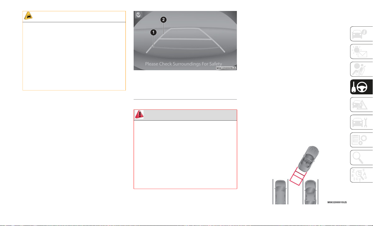
181
Looking At The Display
The vehicle width guide lines are displayed on
the screen as a reference to show the width of
the vehicle compared to the width of the
parking space to be entered while in
REVERSE.
Vehicle Width Guide Lines: these guide lines
serve as a reference showing the width of
the vehicle.
Distance Guide Lines: these lines indicate
the approximate distance from the rear of
the vehicle (the rear edge of the bumper).
The red and yellow lines indicates the
points at about 19
inches (50 cm), for the
re
d line and 39 inches (1 m) for the yellow
li
ne, from the rear bumper (central point of
each line).
Vehicle Width Guide Lines
Rear View Camera Operation
The operating modes of the rear view camera
when the vehicle is in REVERSE vary
depending on traffic, road, and vehicle
conditions. Also, the amount of turning and
the duration of the maneuver vary depending
on the conditions. Therefore, it is important
to check the surrounding conditions and
adapt the steering as necessary.
NOTE:
The images from the rear parking camera
sh
own on the monitor are reversed (mirror
image).
1. Place the gear selector in the REVERSE
p
osition to switch the display to rear view
camera mode.
2. Check the surrounding conditions and
b
egin backing up.
Entering Parking Spot
CAUTION!
To avoid vehicle damage, ParkView
should only be used as a parking aid. The
ParkView camera is unable to view every
obstacle or object in your drive path.
To avoid vehicle damage, the vehicle
must be driven slowly when using
ParkView to be able to stop in time when
an obstacle is seen. It is recommended
that the driver look frequently over his/
her shoulder when using ParkView.
1 — Red Guide Line
2 — Yellow Guide Line
WARNING!
Drivers must be careful when backing up
even when using the ParkView Rear Back
Up Camera. Always check carefully behind
your vehicle, and be sure to check for
pedestrians, animals, other vehicles,
obstructions, or blind spots before backing
up. You are responsible for the safety of
your surroundings and must continue to
pay attention while backing up. Failure to
do so can result in serious injury or death.
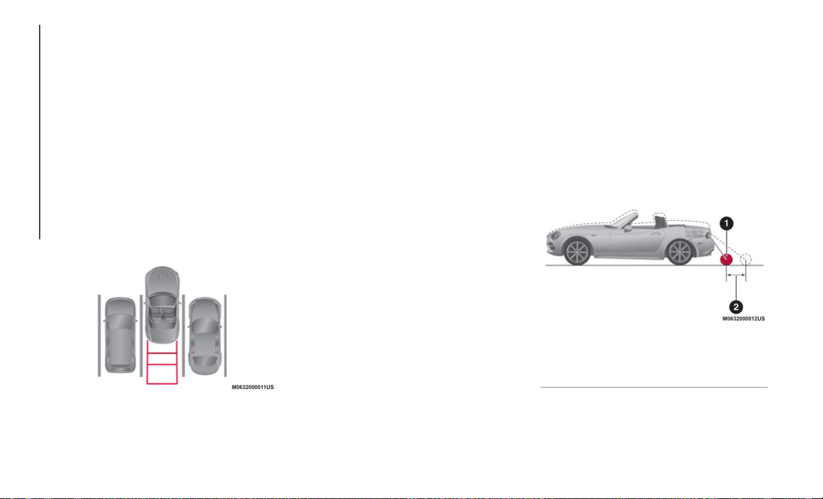
STARTING AND OPERATING
182
3. Once the vehicle starts to enter the
parking space, proceed slowly in
REVERSE while keeping the vehicle
width guide lines away from the two sides
of the parking space.
4. Continue to adjust the steering wheel
u
ntil the vehicle width guide lines are
parallel with the two sides of the parking
space.
5. Once the guide lines are parallel,
s
traighten the steering wheel and reverse
slowly into the parking space. Continue
to check the vehicle’s surroundings and
stop in the best position possible.
Entering Parking Spot
6. When the gear selector is moved from the
R
EVERSE position and put in any other
position, the screen returns to the
previous display mode.
NOTE:
Since there may be some differences
between the displayed image and the real
conditions, always visually inspect the
area behind the vehicle, and the
surrounding areas, to make sure they are
completely clear.
In the image of the parking space (or
garage) shown above, the rear of the
vehicle and the distance guide lines may
seem parallel on the monitor, but may not
be when the parked vehicle is inspected.
When you enter a parking space with a
dividing line only on one side, the dividing
line and the vehicle width guide lines may
appear parallel on the monitor, but may
not be when the parked vehicle is
inspected.
Road Conditions And Displayed Image
There are some differences between what is
shown on the display, and the actual road
conditions.
The different perceptions of distance could
le
ad to an accident. The conditions that can
lead to the different perceptions of distance,
listed below, must be taken into consider
-
ation:
When The Vehicle Slopes Due To The
Weight Of Passengers And Load:
When the vehicle is rear heavy, the object
on
the screen seems to be farther away
than it really is.
Loaded Vehicle Camera Angle
1 — Object
2 — Variance
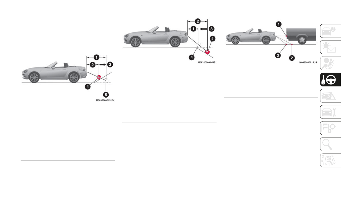
183
When The Road Behind The Vehicle Slopes
Steeply:
When the vehicle is on a steep uphill
(d
ownhill) slope, the object on the screen
seems to be farther away than it really is.
Downhill Camera Angle
Downgrade Camera Angle
Three Dimensional Object Behind The
Vehicle:
Since the distance guide line display is
ba
sed on a flat surface, the distance to a
three dimensional object on the screen
differs from the actual distance.
Three-Dimensional Object Camera View
Adjusting The Image Quality
The image quality can be adjusted with the
gear selector in the REVERSE position.
Four adjustments can be made: brightness,
co
ntrast, tint and color. Give attention to the
vehicle’s surroundings while making adjust
-
ments:
1. Select the icon on the top left of the
s
creen to display the tabs.
2. Select the desired tab.
1
— Distance Between The Vehicle And Ob-
ject Displayed On The Screen
2 — Actual Distance Between The Vehicle
An
d Object
3 — Appears Farther Than Actual Distance
4 — Object At Actual Position
5 — Object On Screen
1 — Distance Between The Vehicle And Ob-
ject Displayed On The Screen
2 — Actual Distance Between The Vehicle
An
d Object
3 — Appears Closer Than Actual Distance
4 — Object On Screen
5 — Object At Actual Position
1 — Object In View
2 — Appears Farther Than Actual
3 — Actual Distance To Object

STARTING AND OPERATING
184
3. Use the cursor to adjust the brightness,
contrast, tint and color. If a reset is
needed, press the reset button.
4. Select the icon on the top left of the
s
creen to close the tabs.
Image Quality Adjustments
REFUELING THE VEHICLE
Refueling The Vehicle
Stop the engine before refueling.
Fuel Requirements
Vehicles with catalytic converters or oxygen
se
nsors must use ONLY UNLEADED FUEL,
which will reduce exhaust emissions and
keep spark plug fouling to a minimum.
Fuel: Premium unleaded fuel.
Octane Rating (Anti-knock index):
91 (R + M)/2 method or above (96
R
O
N or above) (U.S. federal law
requires that octane ratings be
posted on gasoline station pumps).
Regular unleaded fuel with an octane rating
fr
om 87 to 90 (91 to 95 RON) can be used,
but this will reduce performance slightly,
such as reduced engine output, and engine
knocking.
Fuel with a rating lower than 87 octane (91
RO
N) will negatively affect the emission
control system performance and could also
cause engine knocking and serious engine
damage.
While operating on gasoline with an octane
nu
mber of 87, hearing a light knocking
sound from the engine is not a cause for
concern. However, if the engine is heard
making a heavy knocking sound, see your
authorized dealer immediately. Use of gaso
-
line with an octane number lower than 87
c
a
n cause engine failure and may void or not
be covered by the New Vehicle Limited
Warranty. Poor quality gasoline can cause
problems such as hard starting, stalling, and
hesitations. If you experience these symp
-
toms, try another brand of gasoline before
c
o
nsidering service for the vehicle.
Gasoline blended with oxygenates such as
al
cohol or ether compounds are generally
referred to as oxygenated fuels.
The common gasoline blend that can be
us
ed with your vehicle is ethanol blended at
no more than 15%. Gasoline containing
alcohol, such as ethanol or methanol, may be
marketed under the name "Gasohol".
WARNING!
Adjusting the rear-view camera image
quality must always be done when the
vehicle is stationary. Do not adjust the
rear-view camera image quality while
vehicle driving. Adjusting the image
quality (brightness, contrast, color and
tint) of the rear-view camera while driving
the vehicle is dangerous since it could
distract the driver and cause a serious
accident.
185
Vehicle damage and problems resulting from
the use of the following may not be covered
by the New Vehicle Limited Warranty:
Alcohol containing more than 15%
ethanol.
Gasoline or alcohol containing methanol.
Leaded fuel or leaded alcohol.
Reformulated Gasoline
Many areas of the country require the use of
cleaner burning gasoline referred to as
“Reformulated Gasoline”. Reformulated
gasoline contains oxygenates and are specif
-
ically blended to reduce vehicle emissions
an
d improve air quality.
The use of reformulated gasoline is recom-
mended. Properly blended reformulated
g
a
soline will provide improved performance
and durability of engine and fuel system
components.
Gasoline/Oxygenate Blends
Some fuel suppliers blend unleaded gasoline
with oxygenates such as ethanol.
Problems that result from using gasoline
co
ntaining more than 15% ethanol (E-15) or
gasoline containing methanol are not the
responsibility of the manufacturer and may
void or not be covered under New Vehicle
Limited Warranty.
Do Not Use E-85 In Non-Flex Fuel Vehicles
Non-Flex Fuel Vehicles (FFV) are compatible
with gasoline containing up to 15% ethanol
(E-15). Use of gasoline with higher ethanol
content may void the New Vehicle Limited
Warranty.
If a Non-FFV vehicle is inadvertently fueled
wi
th E-85 fuel, the engine will have some or
all of these symptoms:
Operate in a lean mode.
OBD II “Malfunction Indicator Light” on.
Poor engine performance.
Poor cold start and cold drivability.
Increased risk for fuel system component
corrosion.
MMT In Gasoline
Methylcyclopentadienyl Manganese Tricar-
bonyl (MMT) is a manganese-containing
me
tallic additive that is blended into some
gasoline to increase octane. Gasoline
blended with MMT provides no performance
advantage beyond gasoline of the same
octane number without MMT. Gasoline
blended with MMT reduces spark plug life
and reduces emissions system performance
in some vehicles. The manufacturer recom
-
mends that gasoline without MMT be used in
yo
ur vehicle. The MMT content of gasoline
may not be indicated on the gasoline pump;
therefore, you should ask your gasoline
retailer whether the gasoline contains MMT.
MMT is prohibited in Federal and California
reformulated gasoline.
CAUTION!
DO NOT use E-85, gasoline containing
methanol, or gasoline containing more
than 15% ethanol (E-15). Use of these
blends may result in starting and
drivability problems, damage critical fuel
system components, cause emissions to
exceed the applicable standard, and/or
cause the “Malfunction Indicator Light” to
illuminate. Please observe pump labels as
they should clearly communicate if a fuel
contains greater than 15% ethanol (E-15).

STARTING AND OPERATING
186
Materials Added To Fuel
Besides using unleaded gasoline with the
proper octane rating, gasolines that contain
detergents, corrosion and stability additives
are recommended. Using gasolines that have
these additives will help improve fuel
economy, reduce emissions, and maintain
vehicle performance.
Designated TOP TIER Detergent
Gasoline contains a higher level of
de
tergents to further aide in mini-
mizing engine and fuel system
d
e
posits. When available, the usage of TOP
TIER Detergent gasoline is recommended.
Visit
www.toptiergas.com for a list of TOP
TIER Detergent Gasoline Retailers.
Indiscriminate use of fuel system cleaning
ag
ents should be avoided. Many of these
materials intended for gum and varnish
removal may contain active solvents or
similar ingredients. These can harm fuel
system gasket and diaphragm materials.
Fuel System Cautions
NOTE:
Intentional tampering with the emissions
co
ntrol system can result in civil penalties
being assessed against you.
Carbon Monoxide Warnings
CAUTION!
Follow these guidelines to maintain your
vehicle’s performance:
The use of leaded gasoline is prohibited
by Federal law. Using leaded gasoline
can impair engine performance and
damage the emissions control system.
An out-of-tune engine or certain fuel or
ignition malfunctions can cause the
catalytic converter to overheat. If you
notice a pungent burning odor or some
light smoke, your engine may be out of
tune or malfunctioning and may require
immediate service. Contact an autho
-
rized dealer for service assistance.
The use of fuel additives, which are now
being sold as octane enhancers, is not
recommended. Most of these products
contain high concentrations of meth
-
anol. Fuel system damage or vehicle
pe
rformance problems resulting from the
use of such fuels or additives is not the
responsibility of the manufacturer and
may void or not be covered under the
New Vehicle Limited Warranty.
WARNING!
Carbon monoxide (CO) in exhaust gases is
deadly. Follow the precautions below to
prevent carbon monoxide poisoning:
Do not inhale exhaust gases. They
contain carbon monoxide, a colorless
and odorless gas, which can kill. Never
run the engine in a closed area, such as
a garage, and never sit in a parked
vehicle with the engine running for an
extended period. If the vehicle is
stopped in an open area with the engine
running for more than a short period,
adjust the ventilation system to force
fresh, outside air into the vehicle.
Guard against carbon monoxide with
proper maintenance. Have the exhaust
system inspected every time the vehicle
is raised. Have any abnormal conditions
repaired promptly. Until repaired, drive
with all side windows fully open.
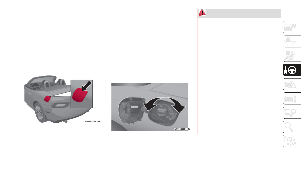
187
Refueling Procedure
Fuel Filler Door
NOTE:
Always use only a designated FCA fuel filler
ca
p or an approved equivalent, available at
your authorized dealer. The wrong cap can
result in a serious malfunction of the fuel
and emission control systems.
When the fuel filler door end is pressed with
th
e doors unlocked, the fuel filler door rises.
Fuel Filler Door
The fuel filler door operates in conjunction
w
i
th the door locking/unlocking mechanism.
To close, press the fuel filler door until a
cl
ick sound is heard.
NOTE:
Make sure to lock both the doors when
leaving the vehicle.
Lock the doors after closing the fuel filler
door. If the fuel filler door is closed after
locking the doors, the fuel filler door
cannot be locked.
Fuel Filler Cap
To remove the fuel filler cap, turn it counter-
clockwise. Attach the removed cap to the
i
n
ner side of the fuel filler door.
Fuel Filler Cap
To close the fuel filler cap, turn it clockwise
u
n
til a click is heard.
WARNING!
Never have any smoking materials lit in
or near the vehicle when the gas cap is
removed or the tank is being filled.
Never add fuel when the engine is
running. This is in violation of most state
and federal fire regulations and may
cause the MIL to turn on.
A fire may result if gasoline is pumped
into a portable container that is inside of
a vehicle. You could be burned. Always
place gas containers on the ground while
filling.
Do not apply any object/plug to the end
of the filler which is not provided for the
vehicle. The use of non-compliant
objects/plugs could cause a pressure
increase inside the tank, resulting in
dangerous situations.
Do not use a mobile phone near the refu-
eling pump: risk of fire.
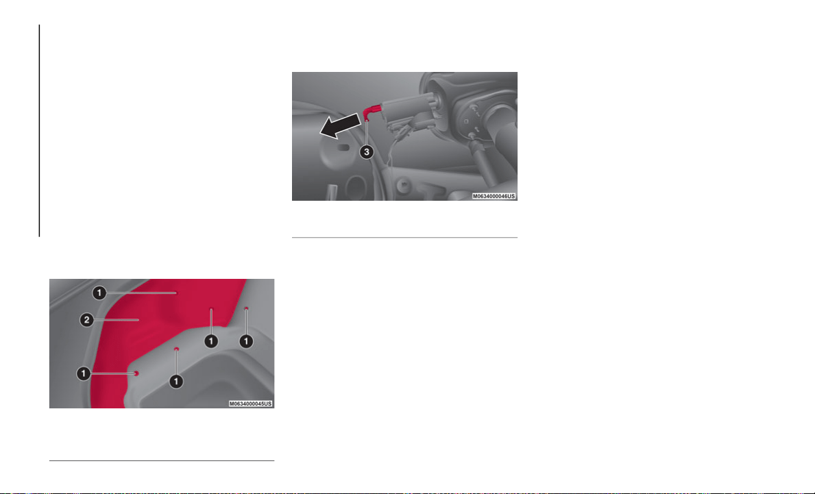
STARTING AND OPERATING
188
Emergency Fuel Filler Door Release
If the battery is discharged, the fuel filler
door cannot be opened. In this case, the fuel
filler door can be opened by taking care of
the discharged battery situation.
If the fuel filler door cannot be opened even
if
the discharged battery situation has been
resolved, the electrical system may have a
malfunction.
In this case, the fuel filler door can be
op
ened using the following procedure as an
emergency measure:
1. Open the trunk and pull the center
s
ection of the plastic fastener and
remove the fastener.
Trunk Interior
2. P
artially peel back the cover inside the
t
runk, then pull the emergency release
lever.
Fuel Door Emergency Release
VEHICLE LOADING
Certification Label
As required by National Highway Traffic
Safety Administration regulations, your
vehicle has a certification label affixed to the
driver's side door or pillar.
This label contains the month and year of
ma
nufacture, Gross Vehicle Weight Rating
(GVWR), Gross Axle Weight Rating (GAWR)
front and rear, and Vehicle Identification
Number (VIN). A Month-Day-Hour (MDH)
number is included on this label and indi
-
cates the Month, Day and Hour of manufac-
ture. The bar code that appears on the
b
o
ttom of the label is your VIN.
Gross Vehicle Weight Rating (GVWR)
The GVWR is the total permissible weight of
your vehicle including driver, passengers,
vehicle, options and cargo. The label also
specifies maximum capacities of front and
rear axle systems (GAWR). Total load must
be limited so GVWR and front and rear
GAWR are not exceeded.
Payload
The payload of a vehicle is defined as the
allowable load weight a truck can carry,
including the weight of the driver, all passen
-
gers, options and cargo.
Gross Axle Weight Rating (GAWR)
The GAWR is the maximum permissible load
on the front and rear axles. The load must be
distributed in the cargo area so that the
GAWR of each axle is not exceeded.
Each axle GAWR is determined by the
co
mponents in the system with the lowest
load carrying capacity (axle, springs, tires or
1 — Plastic Fasteners
2 — Cover
3 — Emergency Release Lever

189
(Continued)
wheels). Heavier axles or suspension compo-
nents sometimes specified by purchasers for
in
creased durability does not necessarily
increase the vehicle's GVWR.
Tire Size
The tire size on the Vehicle Certification
Label represents the actual tire size on your
vehicle. Replacement tires must be equal to
the load capacity of this tire size.
Rim Size
This is the rim size that is appropriate for the
tire size listed.
Inflation Pressure
This is the cold tire inflation pressure for
your vehicle for all loading conditions up to
full GAWR.
Curb Weight
The curb weight of a vehicle is defined as the
total weight of the vehicle with all fluids,
including vehicle fuel, at full capacity condi
-
tions, and with no occupants or cargo loaded
in
to the vehicle. The front and rear curb
weight values are determined by weighing
your vehicle on a commercial scale before
any occupants or cargo are added.
Loading
The actual total weight and the weight of the
front and rear of your vehicle at the ground
can best be determined by weighing it when
it is loaded and ready for operation.
The entire vehicle should first be weighed on
a
commercial scale to insure that the GVWR
has not been exceeded. The weight on the
front and rear of the vehicle should then be
determined separately to be sure that the
load is properly distributed over the front and
rear axle. Weighing the vehicle may show
that the GAWR of either the front or rear
axles has been exceeded but the total load is
within the specified GVWR. If so, weight
must be shifted from front to rear or rear to
front as appropriate until the specified
weight limitations are met. Store the heavier
items down low and be sure that the weight
is distributed equally. Stow all loose items
securely before driving.
Improper weight distributions can have an
ad
verse effect on the way your vehicle steers
and handles and the way the brakes operate.
TOWING TRAILERS
Trailer Towing
Your car is not designed for towing.
Recreational Towing
An example of "recreational towing" is towing
your vehicle behind a motorhome.
The transmission is not designed for towing
th
is vehicle on all four wheels.
CAUTION!
Do not load your vehicle any heavier than
the GVWR or the maximum front and rear
GAWR. If you do, parts on your vehicle can
break, or it can change the way your
vehicle handles. This could cause you to
lose control. Also overloading can shorten
the life of your vehicle.
CAUTION!
DO NOT flat tow this vehicle. Damage to
the drivetrain will result. If this vehicle
requires towing, make sure the drive
wheels are OFF the ground.

STARTING AND OPERATING
190
DRIVING TIPS
Engine Break-In Recommendation
No special break-in is necessary, but a few
precautions in the first 620 miles
(1
,000 km) may add to the performance,
ec
onomy, and life of the vehicle:
Do not race the engine.
Do not maintain one constant speed,
either slow or fast, for a long period of
time.
Do not drive constantly at full-throttle or
high engine rpm for extended periods of
time.
Avoid unnecessary hard stops.
Avoid full-throttle starts.
Saving Fuel And Protection Of The
Environment
How you operate your vehicle determines
how far it will travel on a tank of fuel.
Use these suggestions to help save fuel and
re
duce CO
2
:
Avoid long warm-ups. Once the engine
runs smoothly, begin driving.
Avoid fast starts.
Drive at lower speeds.
Anticipate when to apply the brakes (avoid
sudden braking).
Follow the maintenance schedule and
contact your authorized dealer.
Use the air conditioner only when neces-
sary.
Slow down on rough roads.
Keep the tires properly inflated.
Do not carry unnecessary weight.
Do not rest your foot on the brake pedal
while driving.
Keep the wheels in correct alignment.
Keep windows closed at high speeds.
Slow down when driving in crosswinds and
headwinds.
Hazardous Driving
When driving on ice or in water, snow, mud,
sand, or similar hazards:
Be cautious and allow extra distance for
braking.
Avoid sudden braking and sudden maneu-
vering.
Do not pump the brakes. Continue to press
down on the brake pedal.
If you get stuck, select a lower gear and
accelerate slowly. Do not spin the rear
wheels.
For more traction in starting on slippery
surfaces such as ice or packed snow, use
sand, rock salt, chains, carpeting, or other
nonslip material under the rear wheels.
NOTE:
Use snow chains only on the rear wheels.
Towing this vehicle in violation of the
above requirements can cause severe
transmission damage. Damage from
improper towing is not covered under the
New Vehicle Limited Warranty.
CAUTION! (Continued)
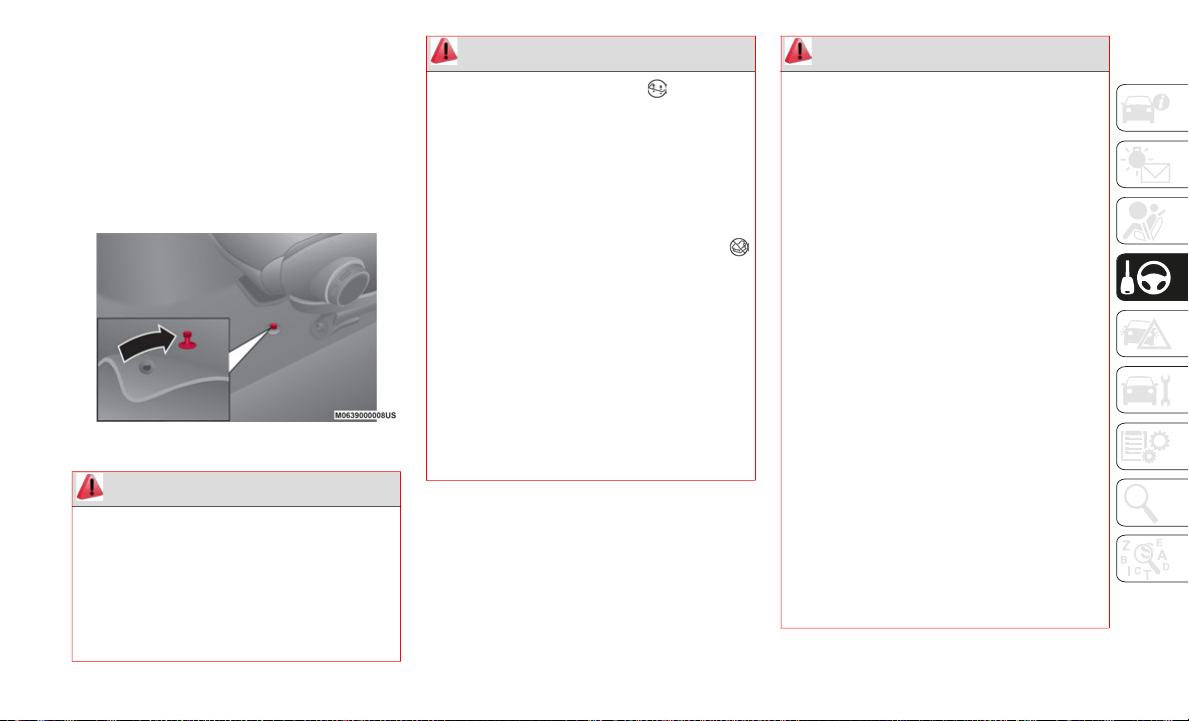
191
(Continued)
(Continued)
(Continued)
Floor Mat Safety Information
Always use floor mats designed to fit the
footwell of your vehicle. Use only floor mats
that leave the pedal area unobstructed and
that are firmly secured so that they cannot
slip out of position and interfere with the
pedals or impair safe operation of your
vehicle in other ways.
Floor Mat Retention Post Location
WARNING!
An improperly attached, damaged, folded,
or stacked floor mat, or damaged floor mat
fasteners may cause your floor mat to
interfere with the accelerator, brake, or
clutch pedals and cause a loss of vehicle
control. To prevent SERIOUS INJURY or
DEATH:
ALWAYS securely attach your floor
mat using the floor mat fasteners. DO
NO
T install your floor mat upside down
or turn your floor mat over. Lightly pull to
confirm mat is secured using the floor
mat fasteners on a regular basis.
ALWAYS REMOVE THE EXISTING
FLOOR MAT FROM THE VEHICLE
before installing any other floor mat.
NEVER install or stack an additional
floor mat on top of an existing floor mat.
ONLY install floor mats designed to fit
your vehicle. NEVER install a floor mat
that cannot be properly attached and
secured to your vehicle. If a floor mat
needs to be replaced, only use a FCA
approved floor mat for the specific make,
model, and year of your vehicle.
WARNING! (Continued)
ONLY use the driver’s side floor mat on
the driver’s side floor area. To check for
interference, with the vehicle properly
parked with the engine off, fully depress
the accelerator, the brake, and the
clutch pedal (if present) to check for
interference. If your floor mat interferes
with the operation of any pedal, or is not
secure to the floor, remove the floor mat
from the vehicle and place the floor mat
in your trunk.
ONLY use the passenger’s side floor mat
on the passenger’s side floor area.
ALWAYS make sure objects cannot fall
or slide into the driver’s side floor area
when the vehicle is moving. Objects can
become trapped under accelerator,
brake, or clutch pedals and could cause
a loss of vehicle control.
NEVER place any objects under the floor
mat (e.g., towels, keys, etc.). These
objects could change the position of the
floor mat and may cause interference
with the accelerator, brake, or clutch
pedals.
WARNING! (Continued)

STARTING AND OPERATING
192
Rocking The Vehicle
NOTE:
Too much rocking may cause engine over-
heating, transmission failure, and tire
d
a
mage.
If you must rock the vehicle to free it from
sn
ow, sand or mud, depress the accelerator
slightly and slowly move the gear selector
from 1 (D) to R.
Winter Driving
Carry emergency gear, including tire chains,
window scraper, flares, a small shovel,
jumper leads, and a small bag of sand or salt.
Contact an authorized dealer to check the
fo
llowing:
Have the proper ratio of antifreeze in the
radiator.
Inspect the battery and its leads. Cold
reduces battery capacity.
Use an engine oil appropriate for the
lowest ambient temperatures that the
vehicle will be driven in.
Inspect the ignition system for damage
and loose connections.
Use winter windshield washer fluid that
will not freeze.
If the vehicle carpet has been removed
and re-installed, always properly attach
carpet to the floor and check the floor
mat fasteners are secure to the vehicle
carpet. Fully depress each pedal to
check for interference with the acceler
-
ator, brake, or clutch pedals then
r
e
-install the floor mats.
It is recommended to only use mild soap
and water to clean your floor mats. After
cleaning, always check your floor mat
has been properly installed and is
secured to your vehicle using the floor
mat fasteners by lightly pulling mat.
WARNING! (Continued)
WARNING!
Fast spinning tires can be dangerous.
Forces generated by excessive wheel
speeds may cause damage, or even failure,
of the axle and tires. A tire could explode
and injure someone. Do not spin your
vehicle's wheels faster than 30
mph
(4
8 km/h) or for longer than 30 seconds
co
ntinuously without stopping when you
are stuck and do not let anyone near a
spinning wheel, no matter what the speed.
CAUTION!
When “rocking” a stuck vehicle by
shifting between DRIVE and REVERSE,
do not spin the wheels faster than
15
mph (24 km/h), or drivetrain damage
ma
y result.
Revving the engine or spinning the
wheels too fast may lead to transmission
overheating and failure. It can also
damage the tires. Do not spin the wheels
above 30
mph (48 km/h) while in gear
(n
o transmission shifting occurring).

193
NOTE:
Remove snow before driving. Snow left on
the windshield is dangerous as it could
obstruct vision.
Drive slowly. Braking performance can be
adversely affected if snow or ice adheres
to the brake components. If this situation
occurs, drive the vehicle slowly, releasing
the accelerator pedal and lightly applying
the brakes several times until the brake
performance returns to normal.
Do not open or close the soft top when the
te
mperature is 41°F (5°C) or less. The mate-
rial of the soft top could be damaged by
f
r
eezing.
Do not apply excessive force to a window
sc
raper when removing ice or frozen snow on
the mirror glass and windshield.
Never use warm or hot water for removing
sn
ow or ice from windows and mirrors as it
could result in the glass cracking.
Snow Tires
If your vehicle is equipped with the tire pres-
sure monitoring system on a vehicle with
r
u
n-flat tires, the system may not function
correctly when using tires with steel wire
reinforcement in the sidewalls.
Use Snow Tires on all Four Wheels:
Do not
exceed the maximum permissible speed for
your snow tires or legal speed limits.
When snow tires are used, select the speci-
fied size and pressure.
Tire Chains
Check local regulations before using tire
ch
ains.
If your vehicle is equipped with the TPMS
sy
stem, the system may not function
correctly when using tire chains.
Install the chains on the rear tires only. Do
no
t use chains on the front tires.
NOTE:
Chains may affect handling.
Do not go faster than 30 mph (50 km/h) or
the chain manufacturer's recommended
limit, whichever is lower.
Drive carefully and avoid bumps, holes,
and sharp turns.
Avoid locked-wheel braking.
Do not use chains on roads that are free of
snow or ice. The tires and chains could be
damaged.
Chains may scratch or chip aluminium
wheels.
WARNING!
Using tires of different size and type
(M+S, Snow) between front and rear axles
can cause unpredictable handling. You
could lose control and have a collision.

STARTING AND OPERATING
194
(Continued)
(Continued)
Driving In Flooded Area
NOTE:
Do not drive the vehicle on flooded roads as
it
could cause short circuit of electrical/elec-
tronic parts, or water enters the engine and
c
a
uses it to lock up (hydro-lock) and stall. If
the vehicle has been immersed in water
contact your authorized dealer.
Although your vehicle is capable of driving
th
rough shallow standing water, consider the
following Cautions and Warnings before
doing so.
CAUTION!
To avoid damage to your vehicle or tires,
observe the following precautions:
Because of restricted traction device
clearance between tires and other
suspension components, it is important
that only traction devices in good condi
-
tion are used. Broken devices can cause
se
rious damage. Stop the vehicle imme-
diately if noise occurs that could indi-
cate device breakage. Remove the
d
a
maged parts of the device before
further use.
Install device as tightly as possible and
then retighten after driving about ½ mile
(0.8
km).
Do not exceed 30 mph (48 km/h).
Drive cautiously and avoid severe turns
and large bumps, especially with a
loaded vehicle.
Do not drive for a prolonged period on
dry pavement.
Observe the traction device manufac-
turer’s instructions on the method of
in
stallation, operating speed, and condi-
tions for use. Always use the suggested
o
p
erating speed of the device manufac-
turer’s if it is less than 30 mph (48 km/
h
)
.
Do not use traction devices on a compact
spare tire.
CAUTION! (Continued)
WARNING!
Driving through standing water limits
your vehicle’s traction capabilities. Do
not exceed 5
mph (8 km/h) when driving
th
rough standing water.
Driving through standing water limits
your vehicle’s braking capabilities,
which increases stopping distances.
Therefore, after driving through standing
water, drive slowly and lightly press on
the brake pedal several times to dry the
brakes.
Failure to follow these warnings may
result in injuries that are serious or fatal
to you, your passengers, and others
around you.
CAUTION!
Always check the depth of the standing
water before driving through it. Never
drive through standing water that is
deeper than the bottom of the tire rims
mounted on the vehicle.
Determine the condition of the road or
the path that is under water and if there
are any obstacles in the way before
driving through the standing water.

195
Overloading
NOTE:
Be careful not to overload your vehicle. The
gr
oss axle weight rating (GAWR) and the
gross vehicle weight rating (GVWR) of the
vehicle are on the Motor Vehicle Safety Stan
-
dard Label on the driver's door frame.
Ex
ceeding these ratings can cause an acci-
dent or vehicle damage. You can estimate
t
h
e weight of the load by weighing the items
(or people) before putting them in the
vehicle.
Driving On Uneven Road
Your vehicle's suspension and underbody
can be damaged if driven on rough/uneven
roads or over speed bumps at excessive
speeds.
Use care and reduce speed when traveling on
ro
ugh/uneven roads or over speed bumps.
Use care not to damage the vehicle's under-
body, bumpers or muffler(s) when driving
un
der the following conditions:
Ascending or descending a slope with a
sharp transition angle.
Ascending or descending a driveway or
trailer ramp with a sharp transition angle.
This vehicle is equipped with low profile tires
al
lowing class-leading performance and
handling. As a result, the sidewall of the tires
are very thin and the tires and wheels can be
damaged if driven through potholes or on
rough/uneven roads at excessive speeds.
Use care and reduce speed when traveling on
ro
ugh/uneven roads or through potholes.
Do not exceed 5 mph (8 km/h) when
driving through standing water. This will
minimize wave effects.
Driving through standing water may
cause damage to your vehicle’s drive-
train components. Always inspect your
v
e
hicle’s fluids (i.e., engine oil, trans-
mission, axle, etc.) for signs of contami-
nation (i.e., fluid that is milky or foamy
i
n
appearance) after driving through
standing water. Do not continue to
operate the vehicle if any fluid appears
contaminated, as this may result in
further damage. Such damage is not
covered by the New Vehicle Limited
Warranty.
Getting water inside your vehicle’s
engine can cause it to lock up and stall
out, and cause serious internal damage
to the engine. Such damage is not
covered by the New Vehicle Limited
Warranty.
CAUTION! (Continued)
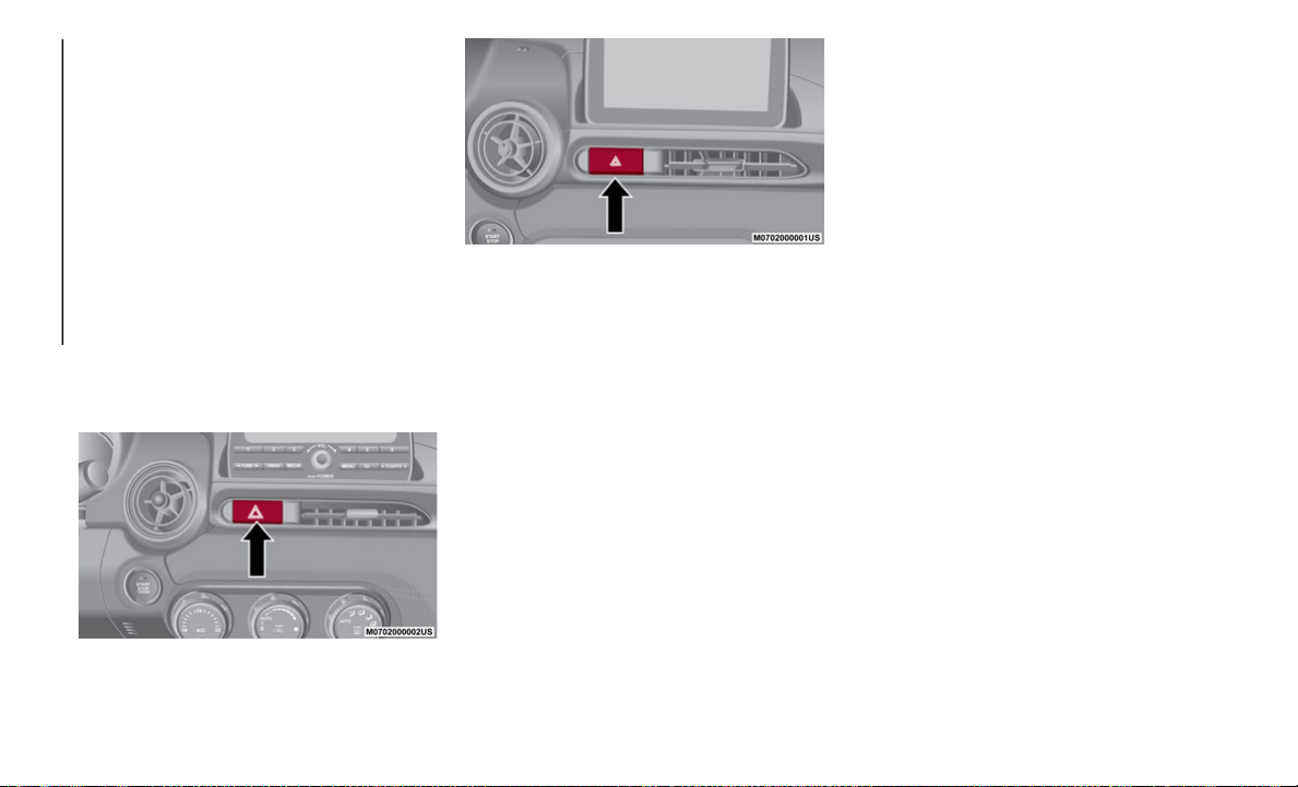
196
IN CASE OF EMERGENCY
HAZARD WARNING LIGHTS
Control
The Hazard Warning Lights should always be
used when you stop on or near a roadway in
an emergency.
The Hazard Warning Light switch is located
on
the center instrument panel below the
radio. Push the switch to turn the Hazard
Warning Lights on or off.
NOTE:
The Hazard Warning Lights warn other
dr
ivers that your vehicle is a traffic hazard
and that they must take extreme caution
when near it.
Hazard Warning Light Switch
Abarth Hazard Warning Light Switch
When the switch is pushed, the Hazard
Wa
rning Lights are active and all directional
turn signals will flash on and off to warn
oncoming traffic of an emergency. Push the
switch a second time to turn off the Hazard
Warning Lights. The hazard warning indi
-
cator lights in the instrument cluster will
f
l
ash simultaneously.
NOTE:
The turn signals do not work while the
Hazard Warning Lights are activated.
Check local regulations about the use of
Hazard Warning Lights while the vehicle is
being towed to verify that it is not in viola
-
tion of the law.
If the brake pedal is pressed while driving
on slippery roads, the emergency stop
signal system could operate causing all of
the directional turn signals to flash.
While the emergency stop signal system is
operating, all of the directional turn
signals automatically flash rapidly to
caution the driver of a vehicle following
behind of a sudden braking situation.
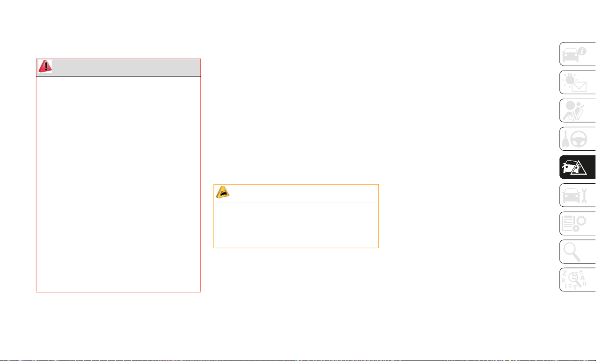
197
REPLACING A BULB
General Instructions
Before replacing a bulb check the
contacts for oxidation.
Replace blown bulbs with others of the
same type and power.
After replacing a headlight bulb, always
check its alignment.
To replace the bulb, contact an authorized
dealer.
When a light is not working, check that the
corresponding fuse is intact before
replacing the bulb. For the location of
fuses, refer to the section on “Replacing
Fuses” in this chapter.
NOTE:
When removing the lens or light unit using
a flathead screwdriver, make sure that the
flathead screwdriver does not contact the
interior terminal. If the flathead screw
-
driver contacts the terminal, a short circuit
ma
y occur.
When the weather is cold or damp or after
heavy rain or washing, the surface of head-
lights or rear lights may steam up and/or
f
o
rm drops of condensation on the inside.
This is a natural phenomenon due to the
difference in temperature and humidity
between the inside and the outside of the
glass which does not indicate a fault and
does not compromise the normal operation
of lighting devices. The mist disappears
quickly when the lights are turned on,
starting from the center of the diffuser,
extending progressively towards the edges.
WARNING!
Before proceeding with the replacement
of the lamp wait until the exhaust pipes
are cool: DANGER OF BURNS!
Modifications or repair of the electrical
system performed incorrectly and
without taking into account the technical
characteristics can cause malfunctions
with the risk of fire.
Halogen lamps contain gas under pres-
sure, in the event of breakage be careful
of
the projection of fragments of glass.
Halogen lamps must be handled by
touching only the metallic part. If the
transparent bulb is in contact with the
fingers, reduces the intensity of the
emitted light and you can also affect the
life of the lamp. In case of accidental
contact, rub the bulb with a cloth damp
-
ened with alcohol and allow to dry.
CAUTION!
Use the protective cover and carton for the
replacement bulb to dispose of the old
bulb promptly and out of the reach of
children.

IN CASE OF EMERGENCY
198
Replacement Bulbs
Light Bulbs Type Power
Front Position LED –
Front Side-Maker Lights (If Equipped With Full-LED Headlights) W5W 5 W
Front Positions/Side-Maker Lights (If Equipped With Halogen Headlights) WY5W 5 W
High Beam (If Equipped With Full-LED Headlights) LED –
High Beam/Daytime Running Lights (DRL) (If Equipped With Halogen Headlights) HB3 60 W
Daytime Running Lights (DRL) (If Equipped With Full-LED Headlights) LED –
Low Beam (If Equipped With Full-LED Headlights) LED –
Low Beam (If Equipped With Halogen Headlights) H11 55 W
Front Direction Indicator Light WY21W 21 W
Side Direction Indicator Light WY5W 5 W
Fog Light H11 55 W
Rear Position Lights LED –
Stop Lights LED –
Center High Mount Stop Lamp (CHMSL) LED –
Rear Direction Indicator Light WY21W 21 W
Rear Side Marker W5W 5 W
Reverse Light W21W 21 W
License Plate Light W5W 5 W
Overhead Light 10 W
Trunk Lid Light 5 W
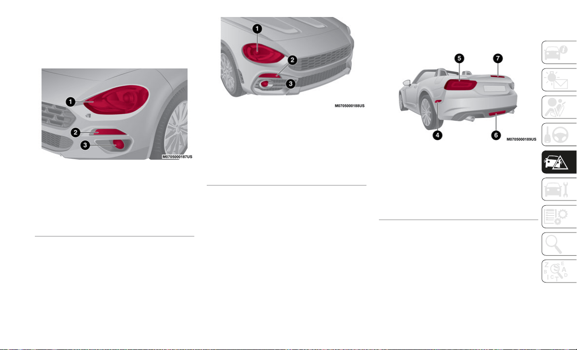
199
Light Bulbs
Front Lights
The bulbs are arranged as follows:
Head Lights
Abarth Head Lights
Rear Lights
The bulbs are arranged as follows:
Rear Lights
1 — High Beam with Daytime Running
Li
ghts (DRL)/Position Light/Low Beam/Side
Marker
2 — Front Indicator Light
3 — Fog Light
1 — High Beam with Daytime Running
Lights (DRL)/Position Light/Low Beam/Side
Marker
2 — Front Indicator Light
3 — Fog Light
4 — Side Marker — If Equipped
5 — Position Light/Stop Light/Rear Direc-
tion Indicator Light
6 — Reverse Light — If Equipped
7 — Third Stop Light
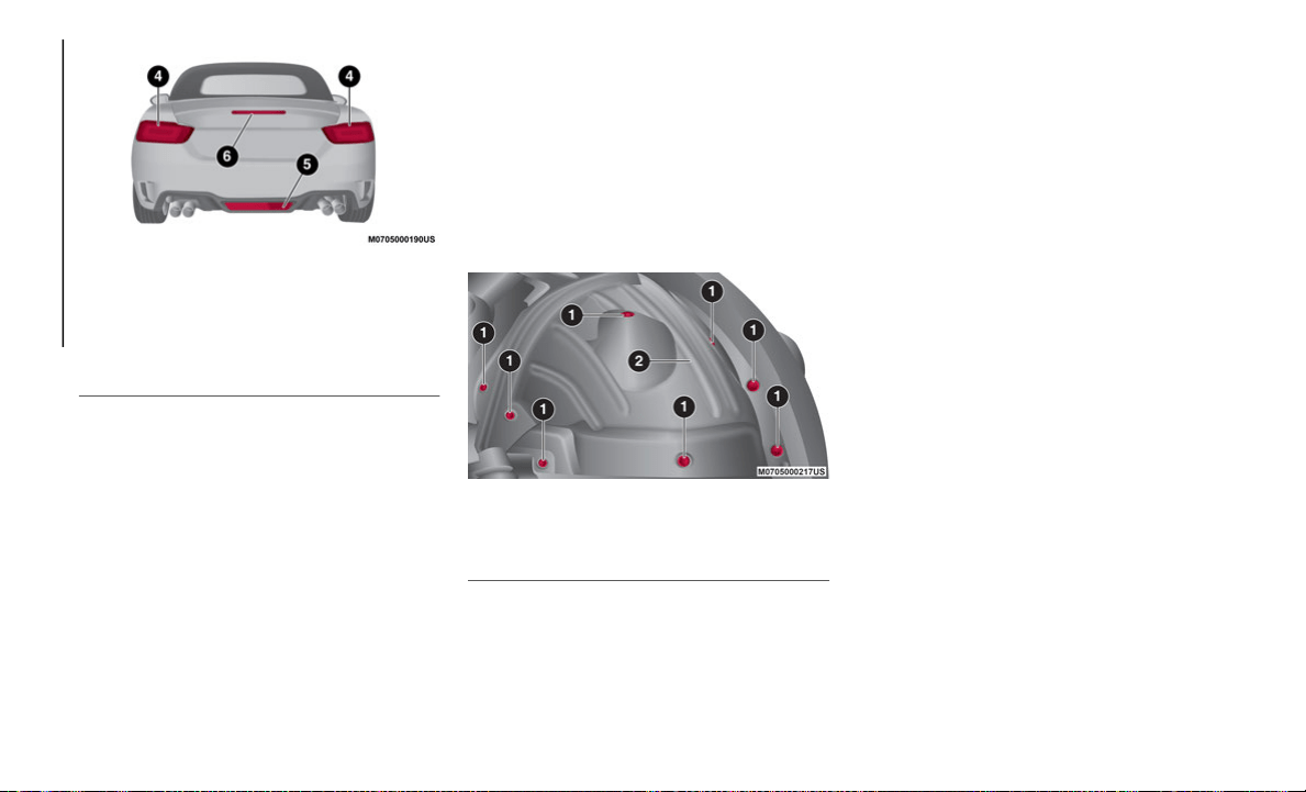
IN CASE OF EMERGENCY
200
Abarth Rear Lights
Replacing Exterior Lights
Headlights (low beam) (If Equipped with
halogen bulb)
Proceed as follows:
1. I
f you are changing the right bulb, start
t
he engine, turn the steering wheel all
the way to the right, and turn off engine.
If you are changing the left bulb, turn the
steering wheel to the left.
2. Make sure the ignition is placed in the
O
FF mode, and the headlight switch is
off.
3. Remove the fasteners in the seven loca-
t
ions and partially peel back the mud
gu
ard.
Mud Guard
4. Turn the cover counterclockwise and
r
emove it, disconnect the connector from
the unit by pressing the tab on the
connector with your finger and pulling
the connector.
5. Turn the socket and bulb assembly coun-
t
erclockwise and remove it.
6. D
isconnect the bulb from the socket.
7
. Install the new bulb in the reverse order
o
f the removal procedure.
Headlights (High Beam) With Daytime Running
Li
ghts (If Equipped With LED Lamps)
Proceed as follows:
1. I
f you are changing the right bulb, start
t
he engine, turn the steering wheel all
the way to the right, and turn off engine.
If you are changing the left bulb, turn the
steering wheel to the left.
2. Make sure the ignition is placed in the
O
FF mode, and the headlight switch is
off.
3. Remove the fasteners in the seven loca-
t
ions and partially peel back the mud
gu
ard.
4. Turn the socket and bulb assembly coun-
t
erclockwise and remove it.
4 — Position Light/Stop Light/Rear Direc-
tion Indicator Light
5 — Reverse Light — If Equipped
6 — Third Stop Light
1 — Fasteners
2 — Mud Guard
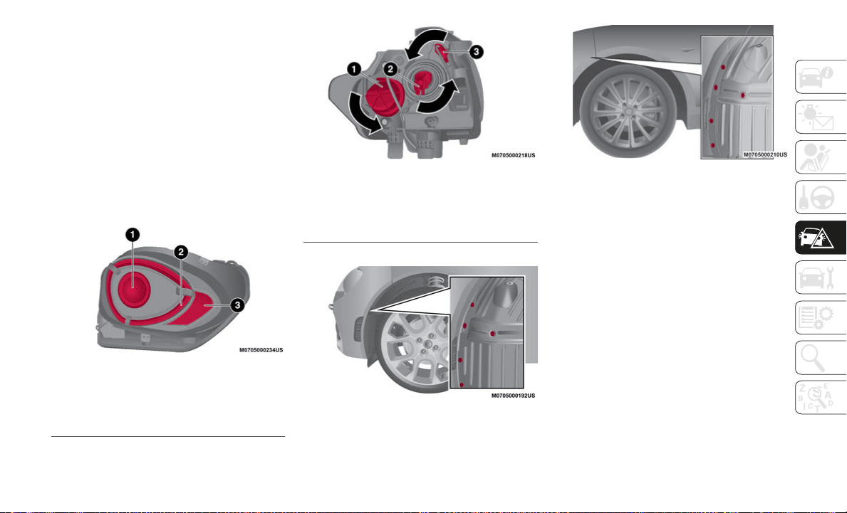
201
5. Turn the cover counterclockwise and
remove it, disconnect the connector from
the unit by pressing the tab on the
connector with your finger and pulling
the connector.
6. Turn the socket and bulb assembly coun-
t
erclockwise and remove it.
7. D
isconnect the bulb from the socket.
8
. Install the new bulb in the reverse order
o
f the removal procedure.
Head Lamp Assembly
Head Lamp Assembly
Abarth Mud Guard
Mud Guard
Front Direction Indicator Lights
Proceed as follows:
1. I
f you are changing the right bulb, start
t
he engine, turn the steering wheel all
the way to the right, and turn off engine.
If you are changing the left bulb, turn the
steering wheel to the left.
2. Make sure the ignition is placed in the
O
FF mode, and the headlight switch is
off.
3. Remove the fasteners in the five loca-
t
ions and partially peel back the mud
gu
ard.
1 — High Beam Lamp
2 — Position Lamp
3 — Daytime Running Lamp
1 — High Beam Lamp
2 — Position Lamp
3 — Daytime Running Lamp
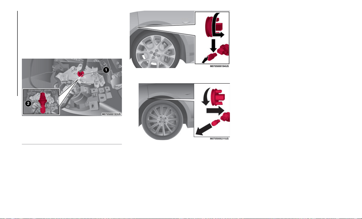
IN CASE OF EMERGENCY
202
4. Disconnect the connector from the unit
by pressing the tab on the connector with
your finger and pulling the connector
rearward.
5. Turn the socket and bulb assembly coun-
t
erclockwise and remove it.
Front Direction Indicator Housing
6. Disconnect the bulb from the socket.
A
barth Direction Indicator Lamp Connector
Direction Indicator Lamp Connector
7. Install the new bulb in the reverse order
o
f the removal procedure.
Fog Lights
Proceed as follows:
1. I
f you are changing the right bulb, start
t
he engine, turn the steering wheel all
the way to the right, and turn off engine.
If you are changing the left bulb, turn the
steering wheel to the left.
2. Make sure the ignition is switched off,
a
nd the headlight switch is off.
3. Remove the fasteners in the five loca-
t
ions and partially peel back the mud
gu
ard.
4. Disconnect the connector from the unit
b
y pressing the tab on the connector with
your finger and pulling the connector.
5. Turn the socket and bulb assembly coun-
t
erclockwise, extract the bulb and
re
move it.
6. Disconnect the bulb from the socket.
7
. Install the new bulb in the reverse order
o
f the removal procedure.
1 — Socket Assembly
2 — Bulb
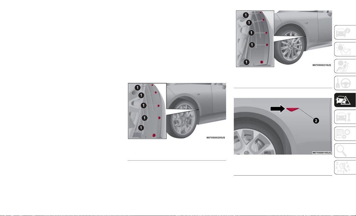
203
Brake lights / Tail lights
Go to an authorized dealer when the replace-
ment of this lights is necessary.
Side Direction Indicator Lights
Proceed as follows:
1. M
ake sure the ignition is placed in the
O
FF mode, and the headlight switch is
off.
2. If you are changing the right bulb, start
t
he engine, turn the steering wheel all
the way to the right, and turn off engine.
If you are changing the left bulb, turn the
steering wheel to the left.
3. Remove the fasteners in the five loca-
t
ions and partially peel back the mud
gu
ard.
4. Disconnect the electrical connector from
t
he bulb by pressing the tab on the
connector with your finger and pulling
the connector.
5. Remove the lens assembly by pressing
t
he tab on the unit with your finger and
pulling the unit forward to compress in
the internal catch, then pull the cluster
outwards.
6. Lift up the lens assembly, and then
r
emove the cluster and install the new
side direction indicator lens assembly in
the reverse order of the removal proce
-
dure.
Abarth Side Direction Indicator
Side Direction Indicator
Abarth Side Direction Indicator
1 — Fasteners
1 — Fasteners
2 — Lens Assembly
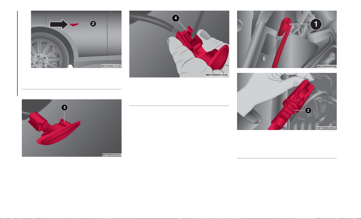
IN CASE OF EMERGENCY
204
Side Direction Indicator
Side Direction Indicator
Front Side Marker (
If Equipped With Halogen
Bulb)
Proceed as follows:
1. R
emove the fasteners in the seven loca-
t
ions and partially peel back the upper
si
de of the mud guard.
2. Turn the socket counterclockwise,
r
emove socket assembly then remove the
bulb.
Front Side Marker
3. Install the new bulb in the reverse order
of the removal procedure.
2 — Lens Assembly
3 — Lens Assembly
4 — Internal Catch
1 — Socket
2 — Bulb Assembly
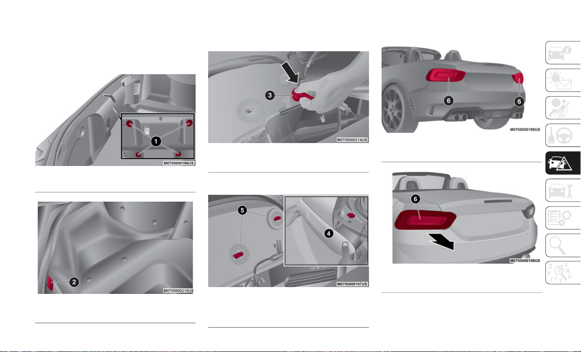
205
Rear Direction Indicator Lights
Proceed as follows:
1. Remove the retainers and the trunk lid
e
nd trim.
Trunk Trim
Trunk Trim
2. Disconnect the connector from the unit
b
y pressing the tab on the connector with
your finger.
Rear Direction Indicator Socket
3. Remove the screw and nuts.
T
aillight Housing Fasteners
4. Pull the taillight housing rearward to
r
emove it.
Abarth Rear of Vehicle
Rear of Vehicle
1 — Retainers
2 — Connector
3 — Connector
4 — Screw
5 — Nuts
6 — Taillight Housing
6 — Taillight Housing
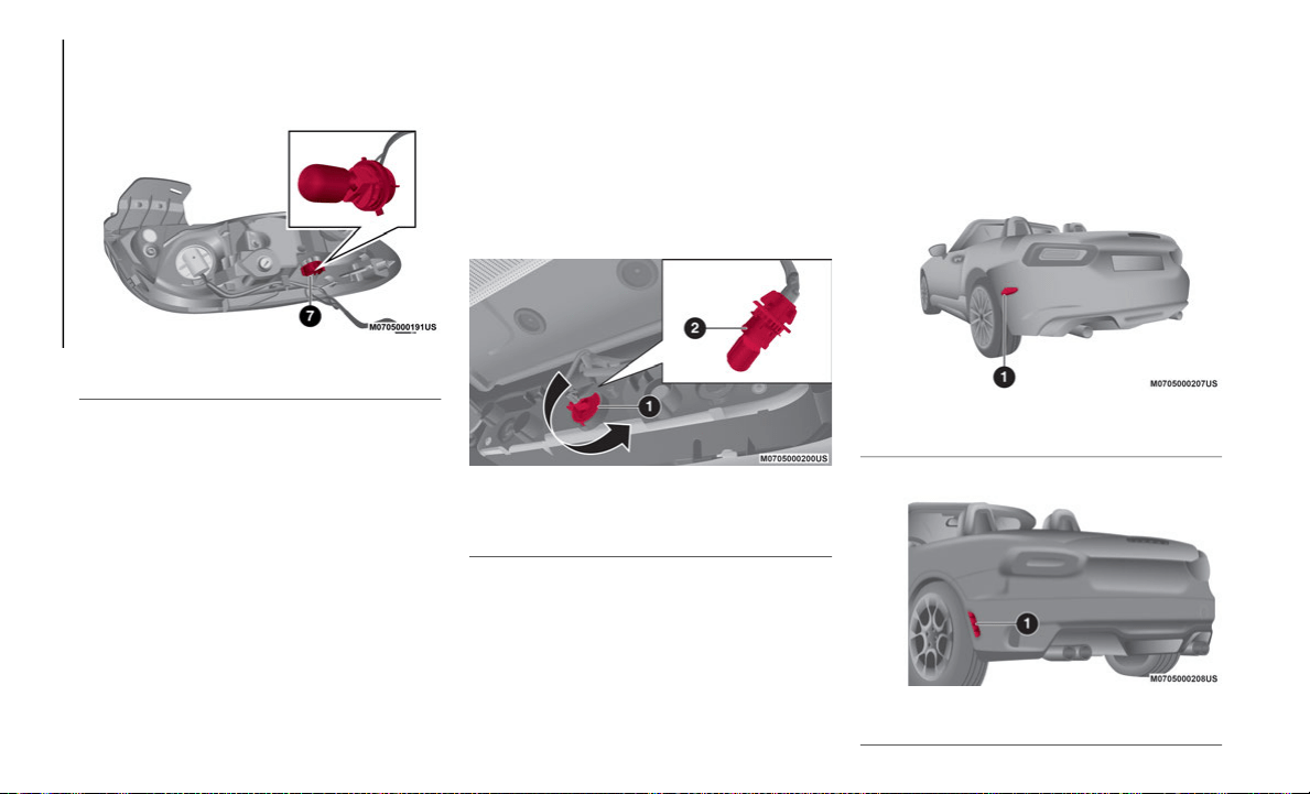
IN CASE OF EMERGENCY
206
5. Turn the socket and bulb assembly coun-
terclockwise to remove from taillight
ho
using, and remove bulb.
Taillight Housing
6. Install the new bulb in the reverse order
o
f the removal procedure.
Reverse Light
Proceed as follows:
1. M
ake sure the ignition is placed in the
O
FF mode, and the headlight switch is
off.
2. Turn the socket assembly counterclock-
w
ise to remove, and remove bulb.
Reverse Light
3. Install the new bulb in the reverse order
o
f the removal procedure.
Rear Side Marker
Proceed as follows:
1. Push the lens assembly rearward to
c
ompress the internal catch, then pull
the lens assembly outwards.
Rear Side Marker
Abarth Rear Side Marker
7 — Socket and Bulb Assembly
1 — Socket Assembly
2 — Bulb
1 — Rear Side Marker Lens Assembly
1 — Rear Side Marker Lens Assembly
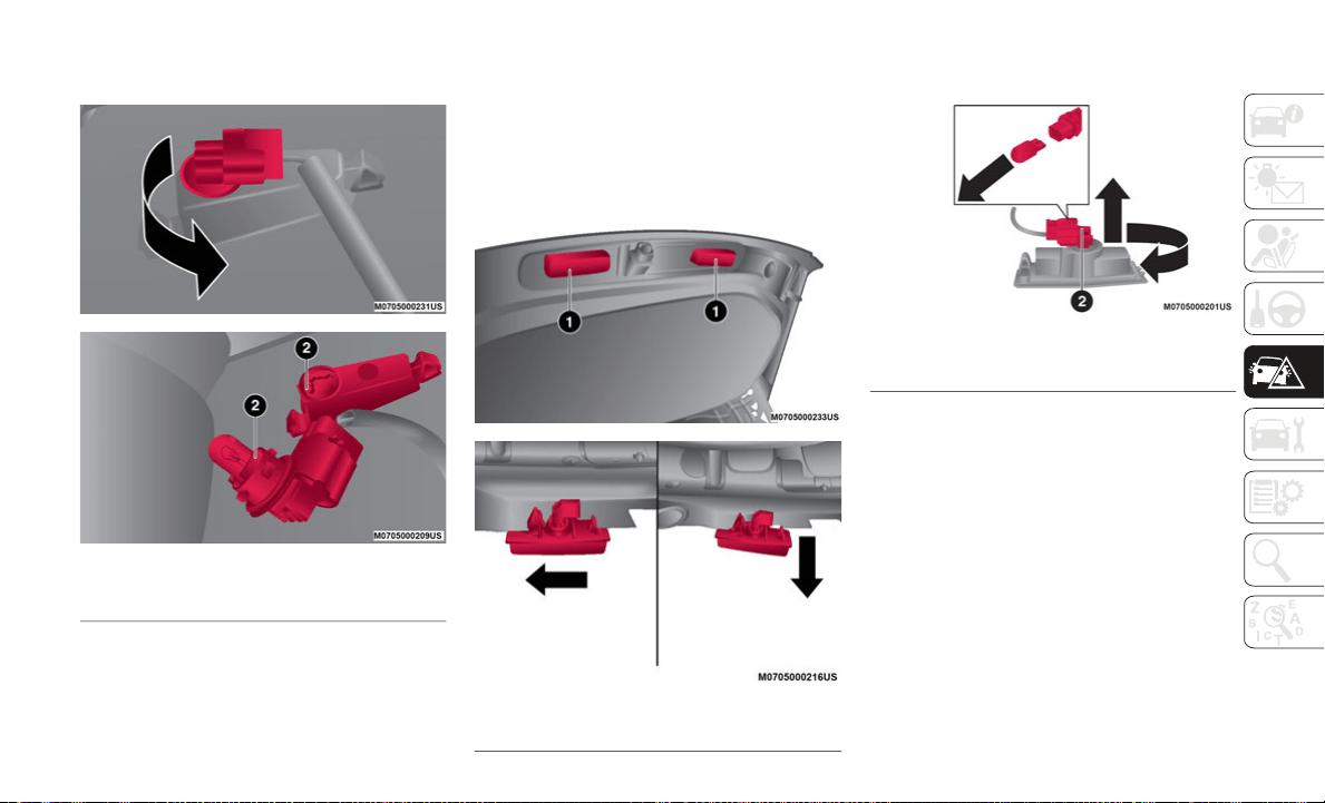
207
2. Turn the socket and bulb assembly coun-
terclockwise to remove, and remove bulb.
Side Marker Housing
3. Install the new bulb and then reinstall
th
e socket in the reverse order of the
removal procedure.
License Plate Lights
Proceed as follows:
1.
Make sure the ignition is placed in th e OFF
mode, and the headlight switch i s off.
2. Slide the unit as shown in the figure t o
remove it.
Trunk Lid
3. Turn the socket and bulb assembly coun-
te
rclockwise and remove bulb.
License Plate Light Housing
4. Install the new bulb in the reverse order
of
the removal procedure. Insert catch
and push the housing back into place.
2 — Socket and Bulb Assembly
1 — License Plate Light Assembly
2 — Socket and Bulb Assembly
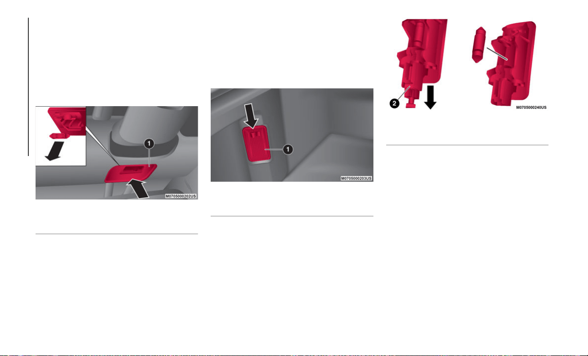
IN CASE OF EMERGENCY
208
Replacing Interior Light Bulbs
Overhead Light
Proceed as follows:
1. Using a suitable tool to prevent damage
t
o the lens, remove the overhead light by
carefully prying on the edge of the lens.
Overhead Light Location
2. Disconnect the bulb by pulling it out.
3
. Install the new bulb in the reverse order
o
f the removal procedure.
Trunk Light
Proceed as follows:
1. Using a suitable tool to prevent damage
t
o the lens, remove the trunk light lens by
carefully prying on the edge of the lens.
Trunk Light
2. Disconnect the connector from the trunk
l
ight lens.
Trunk Light Housing
3. Disconnect the bulb by pulling it out.
4
. Install the new bulb in the reverse order
o
f the removal procedure.
1 — Overhead Light Lens
1 — Trunk Light Lens
2 — Connector
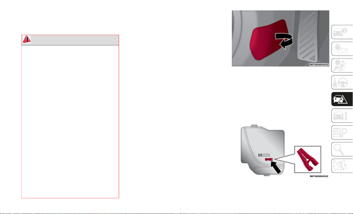
209
REPLACING FUSES
General Information
Your vehicle's electrical system is protected
by fuses.
If any lights, accessories, or controls do not
wo
rk, inspect the appropriate circuit
protector. If a fuse has blown, the inside
element will be melted. If the same fuse
blows again, go to an authorized dealer as
soon as possible.
Fuse location
Fuses are grouped together in two fuse boxes
lo
cated in the interior on the left side of the
vehicle and under the hood.
Interior Fuses
If the electrical system does not work, first
inspect the fuses on the vehicle's left side.
Proceed as follows:
1. M
ake sure the ignition is placed in the
O
FF mode, and other switches are turned
off.
2. Open the fuse panel cover (located near
t
he door).
Fuse Panel Cover
3. Press retaining clip and remove protec-
t
ion cover.
4. P
ull the fuse straight out with the fuse
p
uller provided on the fuse block located
in the engine compartment.
Fuse Puller
WARNING!
When replacing a blown fuse, always use
an appropriate replacement fuse with
the same amp rating as the original fuse.
Never replace a fuse with another fuse of
higher amp rating. Never replace a blown
fuse with metal wires or any other mate
-
rial. Do not place a fuse inside a circuit
b
r
eaker cavity or vice versa. Failure to
use proper fuses may result in serious
personal injury, fire and/or property
damage.
Before replacing a fuse, make sure that
the ignition is off and that all the other
services are switched off and/or disen
-
gaged.
If the replaced fuse blows again, contact
an authorized dealer.
If a general protection fuse for safety
systems (air bag system, braking
system), power unit systems (engine
system, transmission system) or steering
system blows, contact an authorized
dealer.
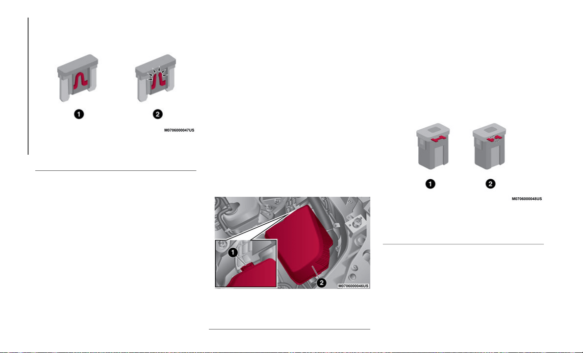
IN CASE OF EMERGENCY
210
5. Inspect the fuse and replace it if it is
blown.
Fuses
6. Insert a new fuse of the same amperage
r
ating, and make sure it fits tightly. If it
does not fit tightly, contact an authorized
dealer. If you have no spare fuses, borrow
one of the same rating from a circuit not
essential to vehicle operation, such as
the audio or outlet circuit.
7. Reinstall the cover and make sure that it
i
s securely installed.
NOTE:
Always replace a fuse with a genuine FCA
fu
se or equivalent of the same rating. Other-
wise you may damage the electric system.
Underhood Fuses
If the headlights or other electrical compo-
nents do not work and the fuses in the cabin
ar
e normal, inspect the fuse block in the
engine compartment. If a fuse is blown, it
must be replaced.
Make sure the ignition is placed in the OFF
mo
de, and other switches are turned off and
remove the fuse block cover. If the lock is
forcefully opened, the fuse block cover may
come in contact with the frame when it is
removed and become scratched.
When removing the cover, remove it slowly
ac
cording to the following procedure:
1. Disengage the rear lock by pressing down
o
n the front tab with your fingers.
Underhood Fuse Block
2. R
emove the front tab while slightly lifting
t
he front of the cover.
3. Remove the cover while lifting it and
s
liding it to the rear.
4. If any fuse but the main fuse is blown,
r
eplace it with a new one of the same
amperage rating.
Fuses
5. R
einstall the cover and make sure that it
i
s securely installed.
1 — Normal Fuse
2 — Blown Fuse
1 — Lock
2 — Cover
1 — Normal Fuse
2 — Blown Fuse
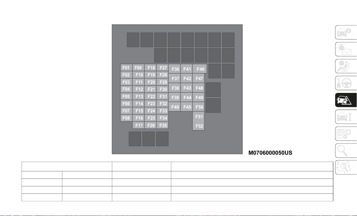
211
Fuse Block (Engine Compartment)
DESCRIPTION FUSE RATING PROTECTED COMPONENT
F01 ENG IG3 5 Amp Engine Control Systems
F02 ENG IG2 5 Amp Engine Control Systems
F03 HORN2 7.5 Amp Horn
F04 C/U IG1 15 Amp For Protection Of Various Circuits

IN CASE OF EMERGENCY
212
F05 ENG IG1 7.5 Amp Engine Control System
F06 — — —
F07 INTERIOR 15 Amp Overhead Light
F08 — — —
F09 AUDIO2 15 Amp Audio System
F10 METER1 10 Amp Instrument Cluster
F11 SRS1 7.5 Amp Air Bag
F12 — — —
F13 RADIO 7.5 Amp Audio System
F14 ENGINE3 20 Amp Engine Control System
F15 ENGINE1 10 Amp Engine Control System
F16 ENGINE2 15 Amp Engine Control System
F17 AUDIO1 25 Amp Audio System
F18 A/C MAG 7.5 Amp Air Conditioner
F19 AT PUMP H/L HI 20 Amp Transmission Control System (If Equipped)
F20 AT 15 Amp Transmission Control System (If Equipped)
F21 D LOCK 25 Amp Power Door Locks
F22 H/L RH 20 Amp Headlight (RH)
F23 ENG + B2 7.5 Amp Engine Control System
F24 TAIL 20 Amp Taillights/Number Plate Lights/Position Lights
F25 — — —
F26 ROOM 25 Amp Overhead Light
F27 FOG 15 Amp Fog Lights
F28 H/CLEAN 20 Amp Headlight Washer (If Equipped)
DESCRIPTION FUSE RATING PROTECTED COMPONENT

213
F29 STOP 10 Amp Stop Lights/Rear Fog Light (If Equipped)
F30 HORN 15 Amp Horn
F31 H/L LH 20 Amp Headlight (LH)
F32 ABS/DSC S 30 Amp ABS/DSC System
F33 HAZARD 15 Amp Hazard Warning Flashers/Direction Indicators Lights
F34 FUEL PUMP 15 Amp Fuel System
F35 ENG + B3 5 Amp Engine Control System
F36 WIPER 20 Amp Windshield Wipers
F37 CABIN + B 50 Amp For Protection Of Various Circuits
F38 — — —
F39 — — —
F40 ABS/DSC M 50 Amp ABS/DSC System
F41 EVVT A/R PUMP 20 Amp Engine Control System
F42 — — —
F43 — — —
F44 FAN2 40 Amp Cooling Fan
F45 ENG.MAIN 40 Amp Engine Control System
F46 EPS 60 Amp Power Steering System
F47 DEFOG 30 Amp Rear Window Defogger
F48 IG2 30 Amp For Protection Of Various Circuits
F49 — — —
F50 HEATER 40 Amp Air Conditioner
F51 — — —
F52 — — —
DESCRIPTION FUSE RATING PROTECTED COMPONENT
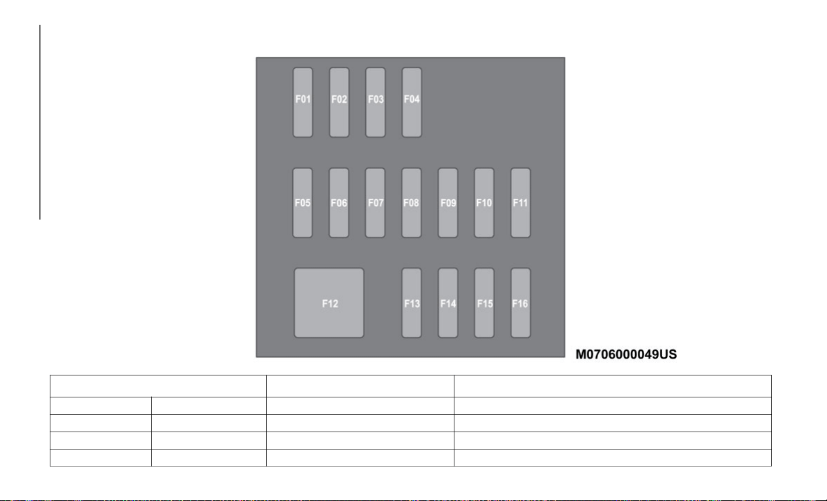
IN CASE OF EMERGENCY
214
Fuse Block Interior
DESCRIPTION FUSE RATING PROTECTED COMPONENT
F01 RHT R 30 Amp —
F02 RHT L 30 Amp —
F03 — — —
F04 — — —
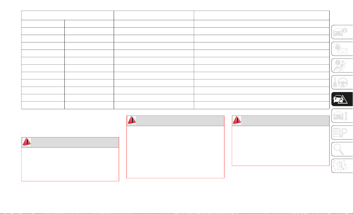
215
(Continued)
(Continued)
JACKING AND TIRE
CHANGING
F05 F.OUTLET 15 Amp Accessory Sockets
F06 — — —
F07 AT IND 7.5 Amp AT Shift Indicator — If Equipped
F08 MIRROR 7.5 Amp Power Control Mirror
F09 R_DECK R 30 Amp —
F10 R_DECK L 30 Amp —
F11 F.WASHER 15 Amp Windshield Washer
F12 P.WINDOW 30 Amp Power Windows
F13 — — —
F14 SRS2/ESCL 15 Amp —
F15 SEAT WARM 20 Amp Heated Seats — If Equipped
F16 M.DEF 7.5 Amp —
DESCRIPTION FUSE RATING PROTECTED COMPONENT
WARNING!
Do not attempt to change a tire on the
side of the vehicle close to moving
traffic. Pull far enough off the road to
avoid the danger of being hit when oper
-
ating the jack or changing the wheel.
Being under a jacked-up vehicle is
dangerous. The vehicle could slip off the
jack and fall on you. You could be
crushed. Never put any part of your body
under a vehicle that is on a jack. If you
need to get under a raised vehicle, take
it to a service center where it can be
raised on a lift.
WARNING! (Continued)
The jack is designed to be used as a tool
for changing tires only. The jack should
not be used to lift the vehicle for service
purposes. The vehicle should be jacked
on a firm level surface only. Avoid ice or
slippery areas.
WARNING! (Continued)
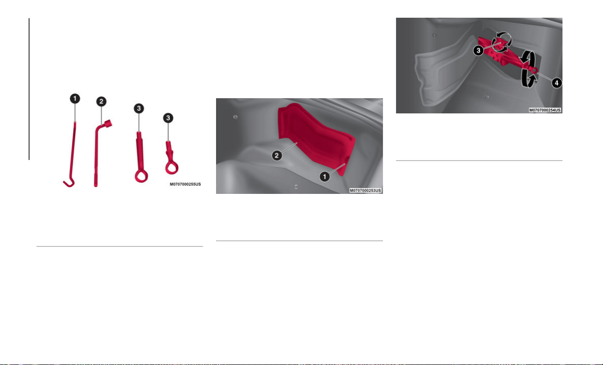
IN CASE OF EMERGENCY
216
Tools Location
Your vehicle may be equipped with a spare
tire, jack, lug wrench and tow eyes. For
details, contact an authorized dealer.
Tools are stored in the trunk.
Jack Tools
Preparations For Jacking
To Remove The Jack
Proceed as follows:
1. In the right side of the trunk, pull the
c
over tab to remove cover.
Jack Location
2. Turn the wing bolt and jack screw coun-
t
erclockwise.
Jack Components
To Secure The Jack
Proceed as follows:
1. Insert the wing bolt into the jack with the
j
ack screw pointing back, and turn the
wing bolt clockwise to temporarily
tighten it.
2. Turn the jack screw clockwise.
3
. Turn the wing bolt completely to secure
t
he jack.
4. Insert the cover tabs and install the
c
over.
1 — Jack Lever
2 — Lug Wrench (If Equipped)
3 — Tow Eyes (If Equipped)
1 — Cover Tab
2 — Jack And Tools Cover
3 — Wing Bolt
4 — Jack Screw
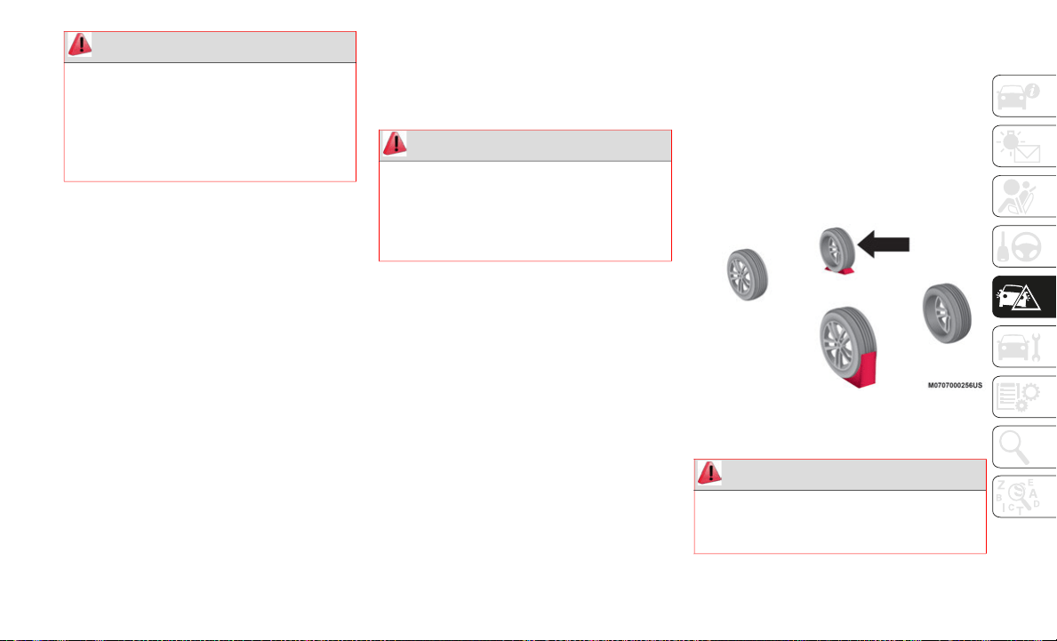
217
(Continued)
Maintenance
Always keep the jack clean.
Make sure the moving parts are kept free
from dirt or rust.
Make sure the screw thread is adequately
lubricated.
Conditions Of Non-Use
Temperatures below -40°F (−40°C).
On sandy or muddy ground.
On uneven ground.
On steep roads.
In extreme weather conditions.
In direct contact with the engine or for
repairs under the vehicle.
On boats.
Jacking Instructions
NOTE:
Make sure the jack is well lubricated before
us
ing it.
Proceed as follows:
1. Stop the vehicle in a position that does
n
ot cause any danger to traffic and lets
you change the tire in safety, as far as
possible from the edge of the driving
lane. The ground must be flat and suffi
-
ciently compact.
2. T
urn on the Hazard Warning Lights and
e
ngage the parking brake.
3. For vehicles with automatic transmis-
s
ion, place the gear selector in PARK (P).
Fo
r vehicles with manual transmission,
place gear selector in REVERSE (R) and
cycle the engine to OFF.
4. Stop the engine. The motor must be kept
o
ff as long as the vehicle is lifted off the
ground.
5. Remove the jack and tools.
6
. Block both the front and rear of the wheel
d
iagonally opposite of the jacking posi-
tion. For example, if changing the right
f
r
ont tire, block the left rear wheel.
Blocking Right Front Tire And Left Rear Tire
Removing A Tire
WARNING!
A loose tire or jack thrown forward in a
collision or hard stop could endanger the
occupants of the vehicle. Always stow the
jack parts and the spare tire in the places
provided. Have the deflated (flat) tire
repaired or replaced immediately.
WARNING!
Do not attempt to change a tire on the side
of the vehicle close to moving traffic. Pull
far enough off the road to avoid being hit
when operating the jack or changing the
wheel.
WARNING!
Carefully follow these tire changing
warnings to help prevent personal injury or
damage to your vehicle:
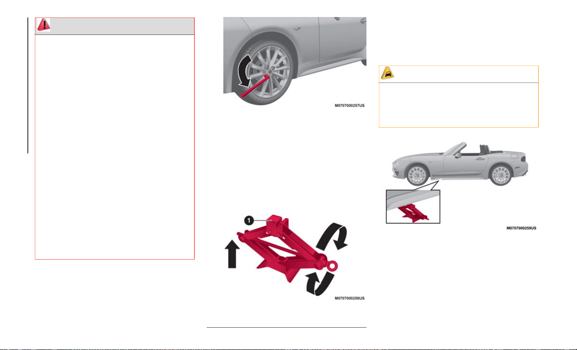
IN CASE OF EMERGENCY
218
Proceed as follows:
1. Loosen the lug nuts by turning them
c
ounterclockwise one turn each, but do
not remove any lug nuts until the tire has
been raised off the ground.
Loosen Lug Nuts Counterclockwise
2. P
lace the jack under the lift point closest
t
o the tire being changed with the jack
head squarely under the jacking location.
3. Turn the jack screw in the direction
s
hown and adjust the jack head so that it
is close to the jacking location.
Raising The Jack
4. Continue raising the jack head gradually
b
y rotating the screw with your hand until
the jack head is inserted into the lift
point.
Front Jacking Location
Always park on a firm, level surface as
far from the edge of the roadway as
possible before raising the vehicle.
Turn on the Hazard Warning flasher.
Block the wheel diagonally opposite the
wheel to be raised.
Apply the parking brake firmly and set
the transmission in PARK.
Do not let any passenger sit in the
vehicle when it is on a jack.
Do not get under the vehicle when it is
on a jack. If you need to get under a
raised vehicle, take it to a service center
where it can be raised on a lift.
Only use the jack in the positions indi-
cated and for lifting this vehicle during a
ti
re change.
If working on or near a roadway, be
extremely careful of motor traffic.
WARNING! (Continued)
1 — Jack Head
CAUTION!
Do not attempt to raise the vehicle by
jacking on locations other than those
indicated in the Jacking Instructions for
this vehicle.
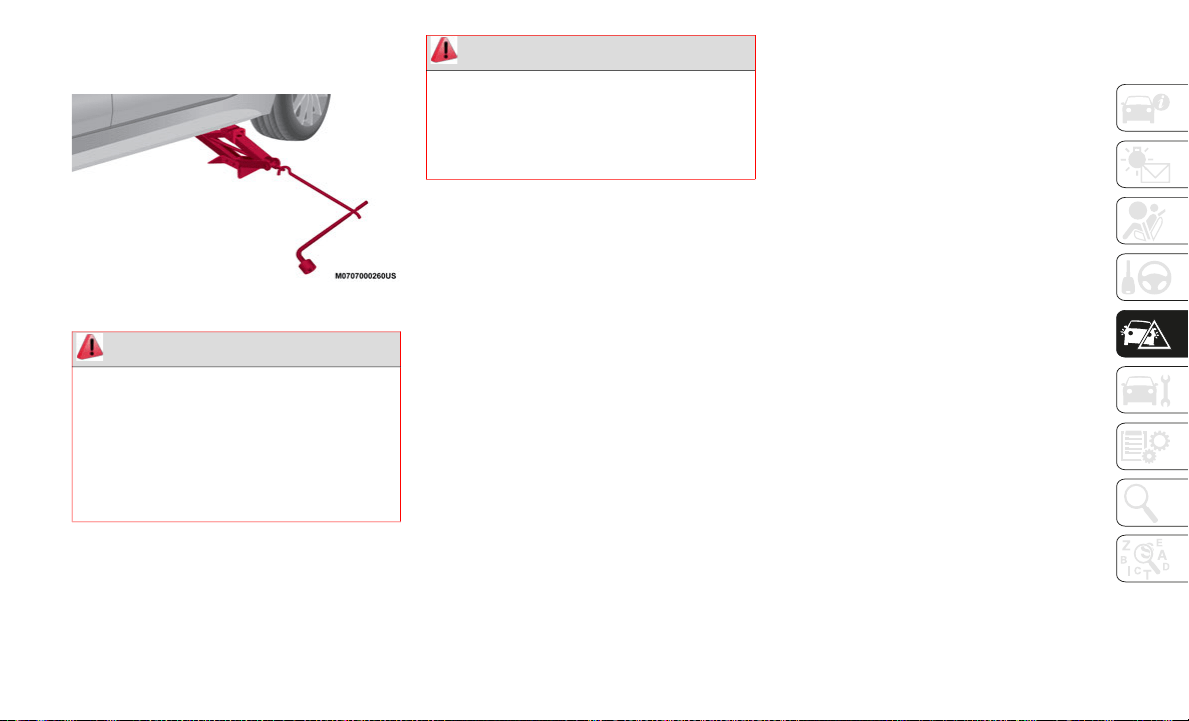
219
5. Insert the jack lever and attach the lug
wrench to tire jack.
Jack With Lug Wrench Attached
6. T
urn the jack handle clockwise and raise
t
he vehicle high enough so that the tire is
just raised off the ground and can be
removed. Before removing the lug nuts,
make sure your vehicle is firmly in posi
-
tion and that it cannot slip or move.
7. Remove the lug nuts by turning them
c ounterclockwise, then remove the wheel.
Locking Lug Nuts — If Equipped
If your vehicle has optional anti-theft wheel
lu
g nuts, one on each wheel will lock the tires
and you must use a special key to unlock
them. This key will attach to the lug wrench.
Register them with the lock manufacturer by
fi
lling out the card provided in the glove
compartment and mailing it in the accompa
-
nying envelope. If you lose this key, contact
an
authorized dealer or use the lock manu-
facturer's order form, which is with the regis-
tration card.
Accessory wheel locks cannot be used on
s
t
eel wheels. This includes situations when
the spare tire is installed. If the spare tire is
installed, one of the original lug nuts (which
should still be in the vehicle) must be
installed in place of the wheel lock.
To Remove An Anti-theft Lug Nut
Proceed as follows:
1. Obtain the special key for the anti-theft
l
ug nut.
2. Place the special key on top of the
a
nti-theft lug nut, and be sure to hold the
key square to it. If you hold the key at an
angle, you may damage both key and nut.
Do not use a power impact wrench.
3. Place the lug wrench on top of the key
a
nd apply pressure. Turn the wrench
counterclockwise.
To Install The Anti-theft Lug Nut
Proceed as follows:
1. Place the special key on top of the nut,
a
nd be sure to hold the key square to it.
If you hold the key at an angle, you may
damage both key and nut. Do not use a
power impact wrench.
2. Place the lug wrench on top of the
s
pecial key, apply pressure, and turn it
clockwise.
WARNING!
Being under a jacked-up vehicle is
dangerous. The vehicle could slip off the
jack and fall on you. You could be crushed.
Never get any part of your body under a
vehicle that is on a jack. If you need to get
under a raised vehicle, take it to a service
center where it can be raised on a lift.
WARNING!
Raising the vehicle higher than necessary
can make the vehicle less stable. It could
slip off the jack and hurt someone near it.
Raise the vehicle only enough to remove
the tire.
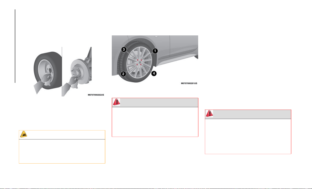
IN CASE OF EMERGENCY
220
Mounting The Tire
Proceed as follows:
1. Remove dirt and grime from the
m
ounting surfaces of the wheel and hub,
including the hub bolts, with a cloth.
Clean Mounting Surface
2. Mount the tire and install the lug nuts
w
ith the beveled edge inward, then
tighten them by hand.
3. Turn the lug wrench counterclockwise
a
nd lower the vehicle. Use the lug
wrench to tighten the nuts in the order
shown.
Lug Nut Tightening Order
4. After tightening the lug nuts, have them
c
hecked with a torque wrench by an
authorized dealer or service station to
verify correct tightness.
5. Remove the tire blocks and store the
t
ools and jack.
6. Check the inflation pressure. Refer to
“
Recommended Tire Inflation Pressure”
in Technical Specifications” for more
information.
With TPMS
Do not push the tire pressure monitoring
s
y
stem set switch after installing the spare
tire. The switch is only to be pushed after
installing the repaired flat tire or installing a
replacement tire.
NOTE:
To prevent the jack and tool from rattling,
s
t
ore them properly.
CAUTION!
Be sure to mount the spare tire with the
valve stem facing outward. The vehicle
could be damaged if the spare tire is
mounted incorrectly.
WARNING!
To avoid the risk of forcing the vehicle off
the jack, do not tighten the wheel nuts
fully until the vehicle has been lowered.
Failure to follow this warning may result in
serious injury.
WARNING!
A loose tire or jack thrown forward in a
collision or hard stop could endanger the
occupants of the vehicle. Always stow the
jack parts and the spare tire in the places
provided. Have the deflated (flat) tire
repaired or replaced immediately.
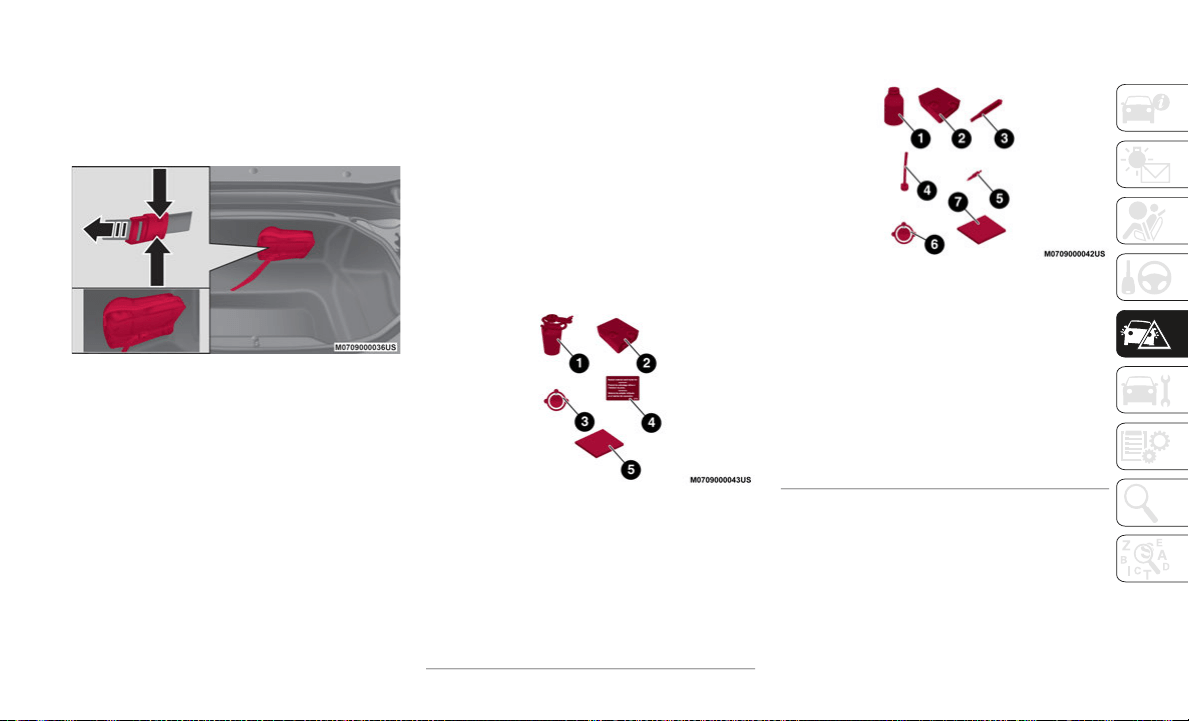
221
TIRE SERVICE KIT
Tire Service Storage
The Tire Service Kit is located inside the
trunk.
Tire Service Kit Location
The Tire Service Kit included with your
ve
hicle is for a temporary repair of a slightly
damaged flat tire resulting from running over
nails or similar sharp objects on the road
surface.
Perform the emergency flat tire repair
wi
thout removing the nail or similar sharp
object which punctured the tire.
NOTE:
Your vehicle is not equipped with a spare
t
i
re. In the event of a flat tire, use the Tire
Service Kit to repair the tire temporarily.
When doing the repair, refer to the instruc
-
tions included in the Tire Service Kit. If an
em
ergency repair was performed on a flat tire
using the Tire Service Kit, contact an autho
-
rized dealer to repair or replace the tire as
so
on as possible.
Tire Service Kit Components And
Operation
The Tire Service Kit includes the following
items:
U.S.A. And Canada Markets:
Tire Service Kit Components — U.S.A. And
Canada Markets
Mexico Market:
Tire Service Kit Components — Mexico
Markets
Tire Service Usage Precautions
The tire sealant cannot be reused. If the
sealant has been used, or is expired,
purchase new tire sealant at an authorized
dealer.
1— Sealant Bottle
2— Compressor
3— Speed Restriction Sticker
4— Repaired Tire Sticker
5— Instructions
1— Tire Sealant
2— Compressor
3— Valve Core Tool
4— Injection Hose
5— Spare Valve Core
6— Speed Restriction Sticker
7— Instructions

IN CASE OF EMERGENCY
222
(Continued)
(Continued)
NOTE:
The Tire Service Kit cannot be used in the
fo
llowing cases. Consult an authorized dealer
if any of these conditions exist:
The period of effective use for the tire
sealant has expired (the period of effec-
tiveness is indicated on the bottle label).
The tear or puncture in the tire exceeds
about 0.16 inches (4 mm).
The damage has occurred to an area of the
tire other than the tread.
The vehicle has been driven with nearly no
air remaining in the tire.
The tire has come off the wheel rim.
Damage to the wheel rim has occurred.
The tire has two or more punctures.
Sealing A Tire With Tire Service Kit
U.S.A. And CANADA Markets:
Proceed as follows:
1. Pull over to a safe location and turn on
t
he vehicle’s Hazard Warning Lights.
2. Verify that the valve stem (on the wheel
w
ith the deflated tire) is in a position that
is near to the ground. This will allow the
WARNING!
Do not attempt to seal a tire on the side
of the vehicle closest to traffic. Pull far
enough off the road to avoid the danger
of being hit when using the Tire Service
Kit.
Do not use Tire Service Kit or drive the
vehicle under the following circum-
stances:
If the puncture in the tire tread is
approximately 1/4 inch (6 mm) or
larger.
If the tire has any sidewall damage.
If the tire has any damage from
driving with extremely low tire pres-
sure.
If the tire has any damage from
driving on a flat tire.
If the wheel has any damage.
If you are unsure of the condition of
the tire or the wheel.
Keep Tire Service Kit away from open
flames or heat sources.
A loose Tire Service Kit thrown forward in
a collision or hard stop could endanger
the occupants of the vehicle. Always
stow the Tire Service Kit in the place
provided. Failure to follow these warn
-
ings can result in injuries that are serious
or
fatal to you, your passengers, and
others around you.
WARNING! (Continued)
Take care not to allow the contents of
Tire Service Kit to come in contact with
hair, eyes, or clothing. Tire Service Kit
sealant is harmful if inhaled, swallowed,
or absorbed through the skin. It causes
skin, eye, and respiratory irritation.
Flush immediately with plenty of water if
there is any contact with eyes or skin.
Change clothing as soon as possible, if
there is any contact with clothing.
Tire Service Kit Sealant solution
contains latex. In case of an allergic
reaction or rash, consult a physician
immediately. Keep Tire Service Kit out
of reach of children. If swallowed, rinse
mouth immediately with plenty of water
and drink plenty of water. Do not induce
vomiting! Consult a physician immedi
-
ately.
WARNING! (Continued)
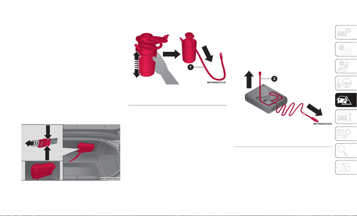
223
Tire Service Kit hoses to reach the valve
stem and keep the Tire Service Kit flat on
the ground. This will provide the best
positioning of the kit when injecting the
sealant into the deflated tire and running
the air pump. Move the vehicle as neces
-
sary to place the valve stem in this posi-
tion before proceeding.
3. P
lace the gear selector in REVERSE (R)
f
or a manual transmission, and PARK (P)
for automatic transmission.
4. Apply the parking brake with the brake
p
edal pressed and cycle the engine OFF.
5. Unload passengers and cargo, then
r
emove the Tire Service Kit.
Tire Service Kit Location
6. Gently shake the sealant bottle to mix the
c
ontents. Then extend the injection hose.
Sealant Bottle With Injection Hose
NOTE:
Do not shake the bottle excessively. Other-
wise, the sealant could spray out of the
injection hose. If the sealant contacts
clothing or other objects, you may not be
able to remove it.
The sealant hardens easily, and injecting
it will be difficult under cold weather
conditions (32 °F (0 °C) or below). Warm
the sealant inside the vehicle to facilitate
injection.
7. Pull out the air compressor hose and the
a
ir compressor plug from the air
compressor.
Air Compressor With Hose And Plug
1 — Injection Hose
2 — Air Compressor Hose
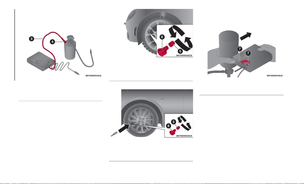
IN CASE OF EMERGENCY
224
8. Install the air compressor hose, which
was pulled out of the air compressor, into
the injection valve of the bottle.
Install Air Compressor To Sealant Bottle
NOTE:
Make sure that the air compressor switch is
o
f
f before inserting the air compressor hose
into the injection valve of the bottle. If the air
compressor hose is not installed to the injec
-
tion valve of the bottle securely, the sealant
ma
y leak.
9. Remove the valve cap from the valve of
t
he flat tire, install the injection hose to
the tire valve, and turn the sleeve to the
right to tighten.
Abarth Valve And Valve Cover
Valve And Valve Cover
10.I
nstall the bottle to the air compressor
a
nd push it in until the left and right tabs
are engaged securely.
Sealant Bottle Into Air Compressor
11.Insert the air compressor plug into the
a
ccessory socket, located deep in the
back of the footwell on the passenger
side, and cycle the ignition to ACC.
NOTE:
When inserting the air compressor plug into
o
r
removing it from the accessory socket,
make sure that the air compressor switch is
off. When turning the air compressor on/off,
use the air compressor switch. Before
3 — Air Compressor Hose
4 — Injection Valve
5 — Valve Cap
6 — Valve
5 — Valve Cap
6 — Valve
7 — Air Compressor Tabs
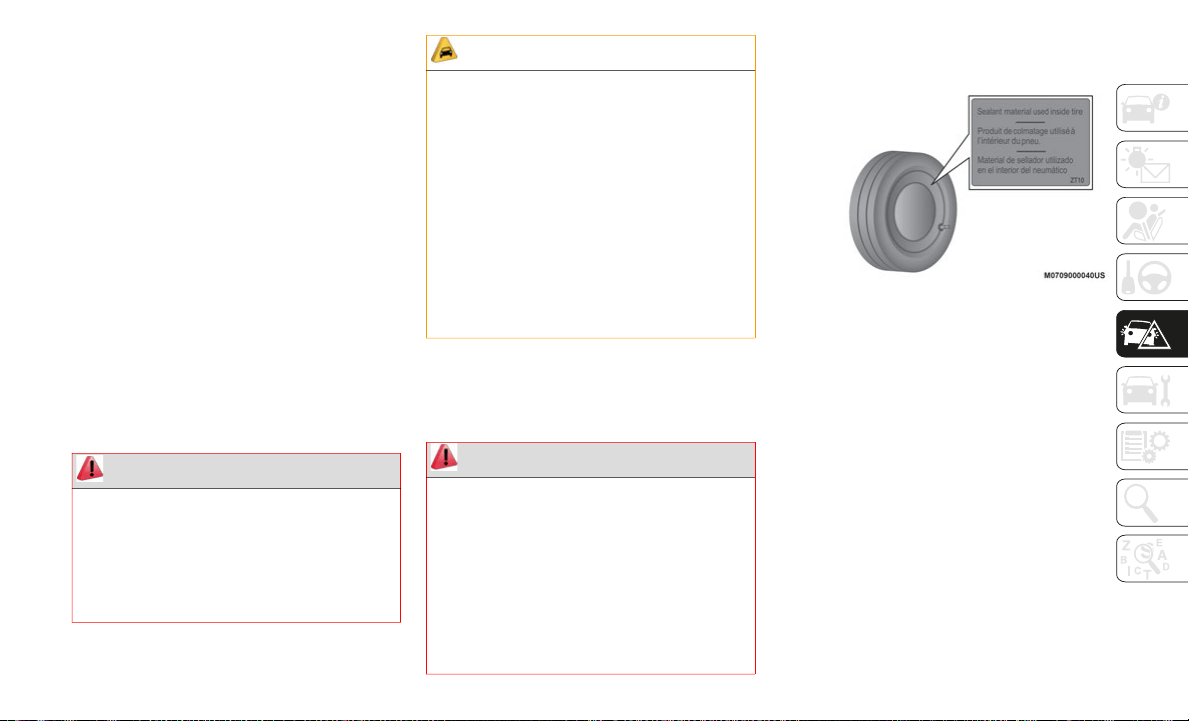
225
checking the tire inflation pressure using the
tire pressure gauge, turn the air compressor
switch off.
12.The sealant is injected into the tire when
t
he air compressor is switched on. After
the sealant is injected completely, wait
until the tire inflation pressure increases
to the specified tire inflation pressure.
For the correct pressure, check the tire
inflation pressure label on the driver's
door frame.
NOTE:
The inflation pressure may increase to about
4
3
.5 psi (3 Bar) temporarily to inject the
sealant through the valve. Normally, the
inflation pressure decreases gradually and it
reaches the actual inflation pressure after
about 30 seconds.
13.Adhere the speed restriction sticker to an
a
rea where it can be viewed easily by the
driver.
14.Adhere the repaired tire sticker to the
w
heel of the flat tire.
Repaired Tire Sticker
15.W
hen the tire inflates to the specified tire
i
nflation pressure, turn the air
compressor switch off, turn the sleeve of
the injection hose to the left, and pull it
out of the tire valve.
WARNING!
Never use the air compressor above 3 Bar
(43.5 psi). Using the air compressor at an
inflation pressure above 3 Bar (43.5 psi)
continuously is dangerous. If the air
compressor overheats, hot air will be
exhausted and you could get burned.
CAUTION!
If the tire inflation pressure does not
increase, repair of the tire is not
possible. If the tire does not reach the
specified tire inflation pressure within
10
minutes, it may have received exten-
sive damage. In this case, the repair
us
ing the tire service kit was not
successful.
Do not operate the air compressor for a
continuous 10 minutes or longer
be
cause using it for long periods could
cause a malfunction.
WARNING!
Do not adhere the speed restriction sticker
to the padded area on the steering wheel.
Adhering the speed restriction sticker to
the padded area on the steering wheel is
dangerous because the air bag may not
operate (deploy) normally resulting in
serious injury. In addition, do not adhere
the sticker to areas where warning lights or
the speedometer cannot be viewed.

IN CASE OF EMERGENCY
226
(Continued)
16.Remove the air compressor hose from the
injection valve of the bottle. Then, install
the injection hose to the injection valve
of the bottle to prevent leakage of any
remaining sealant.
Install Injection Hose To Sealant Bottle
NOTE:
The remaining sealant in the hose may spray
o
u
t when the hose is removed. Remove the
hose carefully because you may not be able
to remove the sealant contacting clothing or
other objects.
17.Install the tire valve cap.
1
8.Place the Tire Service Kit back into its
s
torage location.
19.Start driving immediately to spread the
s
ealant in the tire.
NOTE:
Carefully drive the vehicle at a speed of
50
mph (80 km/h) or less. If the vehicle is
dr
iven at a speed of 50 mph (80 km/h) or
mo
re, the vehicle may vibrate.
NOTE:
With TPMS System:
i
f the tire is not properly
inflated, the warning light will illuminate.
After driving the vehicle for about
10 minutes or 3 miles (5 km), connect
th
e air compressor to the tire using Step
nine of the procedure, and check the tire
inflation pressure using the tire pressure
gauge on the air compressor. If the tire
inflation pressure is lower than the speci
-
fied tire inflation pressure, turn the air
c
o
mpressor on and wait until it reaches
the specified tire inflation pressure.
The Tire Service Kit is completed success-
fully if the tire inflation pressure does not
de
crease. Carefully drive the vehicle to the
nearest authorized dealer immediately and
have the flat tire replaced. Replacement
with a new tire is recommended. If the tire
is to be repaired or reused, consult an
authorized dealer.
NOTE:
If an emergency flat tire repair has been
performed using the Tire Service Kit, FCA
recommends that the tire be replaced with
a new one as soon as possible. If the tire
is to be repaired or reused, contact an
authorized dealer.
The wheel can be reused if the sealant
adhering to it is removed. However,
replace the valve with a new one.
Sealing A Tire With Tire Service Kit
WARNING!
Do not attempt to seal a tire on the side
of the vehicle closest to traffic. Pull far
enough off the road to avoid the danger
of being hit when using the Tire Service
Kit.
Do not use Tire Service Kit or drive the
vehicle under the following circum-
stances:
If the puncture in the tire tread is
approximately 1/4 inch (6 mm) or
larger.
If the tire has any sidewall damage.
227
(Continued)
Mexico Market
Proceed as follows:
1. Pull over to a safe location and turn on
t
he vehicle’s Hazard Warning Lights.
2. Verify that the valve stem (on the wheel
w
ith the deflated tire) is in a position that
is near to the ground. This will allow the
Tire Service Kit hoses to reach the valve
stem and keep the Tire Service Kit flat on
the ground. This will provide the best
positioning of the kit when injecting the
sealant into the deflated tire and running
the air pump. Move the vehicle as neces
-
sary to place the valve stem in this posi-
tion before proceeding.
3. P
lace the gear selector in REVERSE (R)
f
or a manual transmission, or PARK (P)
for automatic transmission.
4. Apply the parking brake with the brake
p
edal pressed and cycle the engine OFF.
If the tire has any damage from
driving with extremely low tire pres-
sure.
If the tire has any damage from
driving on a flat tire.
If the wheel has any damage.
If you are unsure of the condition of
the tire or the wheel.
Keep Tire Service Kit away from open
flames or heat sources.
A loose Tire Service Kit thrown forward in
a collision or hard stop could endanger
the occupants of the vehicle. Always
stow the Tire Service Kit in the place
provided. Failure to follow these warn
-
ings can result in injuries that are serious
or
fatal to you, your passengers, and
others around you.
WARNING! (Continued)
Take care not to allow the contents of
Tire Service Kit to come in contact with
hair, eyes, or clothing. Tire Service Kit
sealant is harmful if inhaled, swallowed,
or absorbed through the skin. It causes
skin, eye, and respiratory irritation.
Flush immediately with plenty of water if
there is any contact with eyes or skin.
Change clothing as soon as possible, if
there is any contact with clothing.
Tire Service Kit Sealant solution
contains latex. In case of an allergic
reaction or rash, consult a physician
immediately. Keep Tire Service Kit out
of reach of children. If swallowed, rinse
mouth immediately with plenty of water
and drink plenty of water. Do not induce
vomiting! Consult a physician immedi
-
ately.
WARNING! (Continued)
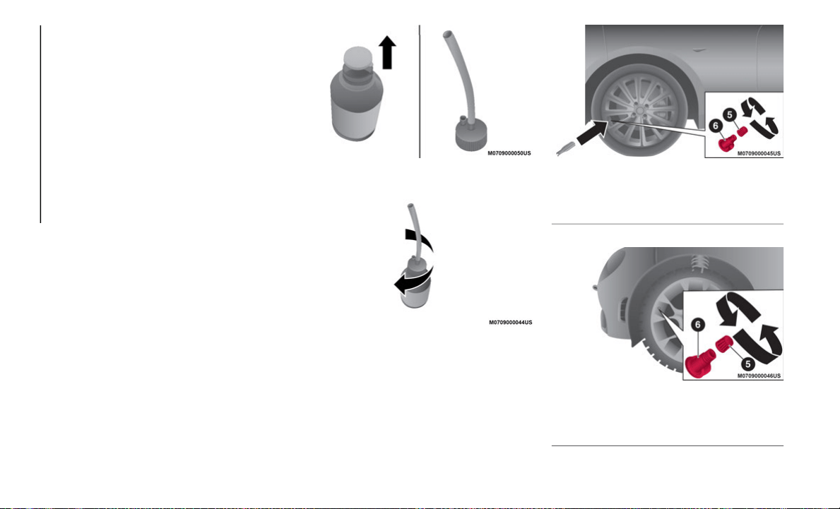
IN CASE OF EMERGENCY
228
5. Unload passengers and cargo, then
remove the Tire Service Kit.
6. Gently shake the tire sealant. If the bottle
i
s shaken after the injection hose is
screwed on, tire sealant could spray out
from the injection hose. Tire sealant
contacting clothing or other objects may
be impossible to remove. Shake the
bottle before screwing on the injection
hose.
NOTE:
Do not shake the bottle excessively. Other-
wise, the sealant could spray out of the
injection hose, and if the sealant contacts
clothing or other objects, you may not be
able to remove it.
The sealant hardens easily and injecting it
will be difficult under cold weather condi-
tions 32 °F (0 °C) or below. Warm the
sealant inside the vehicle to facilitate
injection.
7. Remove the cap from the bottle and
s
crew on the injection hose with the
bottle's inner cap left on to break the
inner cap.
Remove Cap To Sealant Bottle
Attach Injection Hose To Sealant Bottle
8. R
emove the valve cap from the flat tire.
P
ush the back of a valve core tool to the
core of the tire valve and bleed out all of
the remaining air.
Valve And Valve Cover
Abarth Valve And Valve Cover
5 — Valve Cap
6 — Tire Valve
5 — Valve Cap
6 — Tire Valve
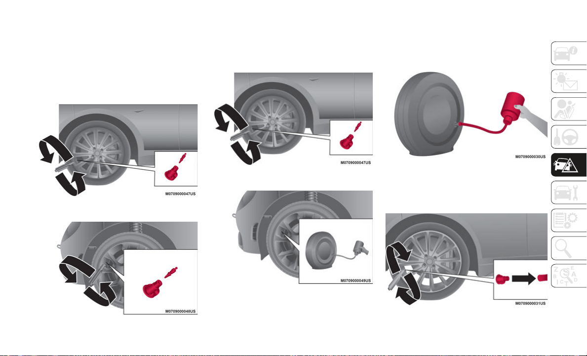
229
NOTE:
If there is air remaining in the tire when the
va
lve core is removed, the valve core could
fly out. Remove the valve core carefully.
9. Turn the valve core counterclockwise
w
ith the valve core tool and remove the
valve core.
Turn Valve Core Counterclockwise
Abarth Turn Valve Core Counterclockwise
NOTE:
Store the valve core in a place where it will
no
t get dirty.
10.Insert the injection hose into the valve.
I
njection Hose Into Valve
Abarth Injection Hose Into Valve
11.H
old the bottom of the bottle upright,
s
queeze the bottle with your hands, and
inject the entire amount of tire sealant
into the tire.
Squeeze Sealant Into Tire
12.Pull out the injection hose from the
v
alve.
Turn Valve Core Clockwise To Reinstall
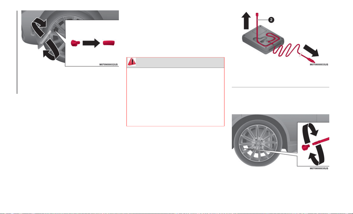
IN CASE OF EMERGENCY
230
Abarth Turn Valve Core Clockwise To Reinstall
13.Reinsert the valve core into the valve and
t
urn it clockwise to install.
NOTE:
The tire sealant cannot be reused. If the
tire sealant kit has been used, or is
expired, purchase a new one at an autho
-
rized dealer.
Do not throw away the empty tire sealant
bottle after use. Return the empty tire
sealant bottle to an authorized dealer
when replacing the tire. The empty tire
sealant bottle will need to be used to
extract and dispose of the used sealant
from the tire.
14.Install the injection hose to the tab of the
b
ottle to prevent leakage of any
remaining sealant.
15.Adhere the speed restriction sticker to an
a
rea where it can be viewed easily by the
driver.
16.Pull out the air compressor hose and the
a
ir compressor plug from the air
compressor.
Air Compressor With Hose And Plug
17.Install the air compressor hose to the tire
v
alve.
Air Compressor Hose Into Valve
WARNING!
Do not adhere the speed restriction sticker
to the padded area on the steering wheel.
Adhering the speed restriction sticker to
the padded area on the steering wheel is
dangerous because the air bag may not
operate (deploy) normally resulting in
serious injury. In addition, do not adhere
the sticker to areas where warning lights or
the speedometer cannot be viewed.
2 — Air Compressor Hose
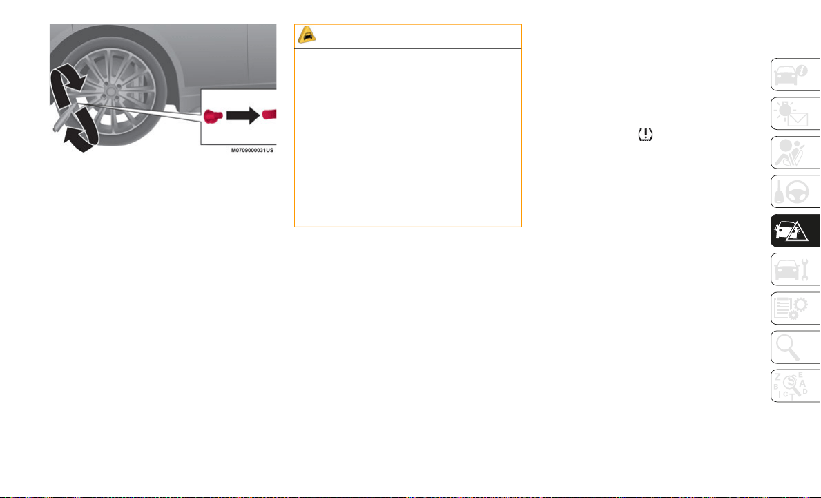
231
Abarth Air Compressor Hose Into Valve
18.Insert the air compressor plug into the
a
ccessory socket, located deep in the
back of the footwell on the passenger
side, and cycle the ignition to ACC.
19.Turn the air compressor switch on and
i
nflate the tire carefully to the correct
inflation pressure. For the correct pres
-
sure, check the tire inflation pressure
la
bel on the driver's door frame.
NOTE:
When inserting the air compressor plug into
o
r
removing it from the accessory socket,
make sure that the air compressor switch is
off. When turning the air compressor on/off,
use the air compressor switch. Before
checking the tire inflation pressure using the
tire pressure gauge, turn the air compressor
switch off.
NOTE:
If the tire has been over inflated, loosen the
s
c
rew cap on the air compressor and bleed
some of the air out.
20.When the tire inflates to the specified tire
i
nflation pressure, turn the air
compressor switch off, turn the sleeve of
the air compressor hose to the left, and
pull it out of the tire valve.
21.Install the tire valve cap.
2
2.Place the Tire Service Kit back into its
s
torage location.
23.Start driving immediately to spread the
s
ealant in the tire.
NOTE:
Carefully drive the vehicle at a speed of
50 mph (80 km/h) or less. If the vehicle is
dr
iven at a speed of 50 mph (80 km/h) or
mo
re, the vehicle may vibrate.
With TPMS System: if the tire is not prop-
erly inflated, the warning light will illu-
minate.
After driving the vehicle for about
10 minutes or 3 miles (5 km), connect
th
e air compressor to the tire using step
nine of the procedure, and check the tire
inflation pressure using the tire pressure
gauge on the air compressor. If the tire
inflation pressure is lower than the speci
-
fied tire inflation pressure, turn the air
c
o
mpressor on and wait until it reaches
the specified tire inflation pressure;
The emergency flat tire repair is
completed successfully if the tire inflation
pressure does not decrease. Carefully
drive the vehicle to the nearest authorized
dealer and have the flat tire replaced.
Replacement with a new tire is recom
-
mended. If the tire is to be repaired or
r
e
used, contact an authorized dealer.
CAUTION!
If the tire inflation pressure does not
increase, repair of the tire is not
possible. If the tire does not reach the
specified tire inflation pressure within
10
minutes, it may have received exten-
sive damage. In this case, the repair
us
ing the tire service kit was not
successful.
Do not operate the air compressor for a
continuous 10 minutes or longer
be
cause using it for long periods could
cause a malfunction.
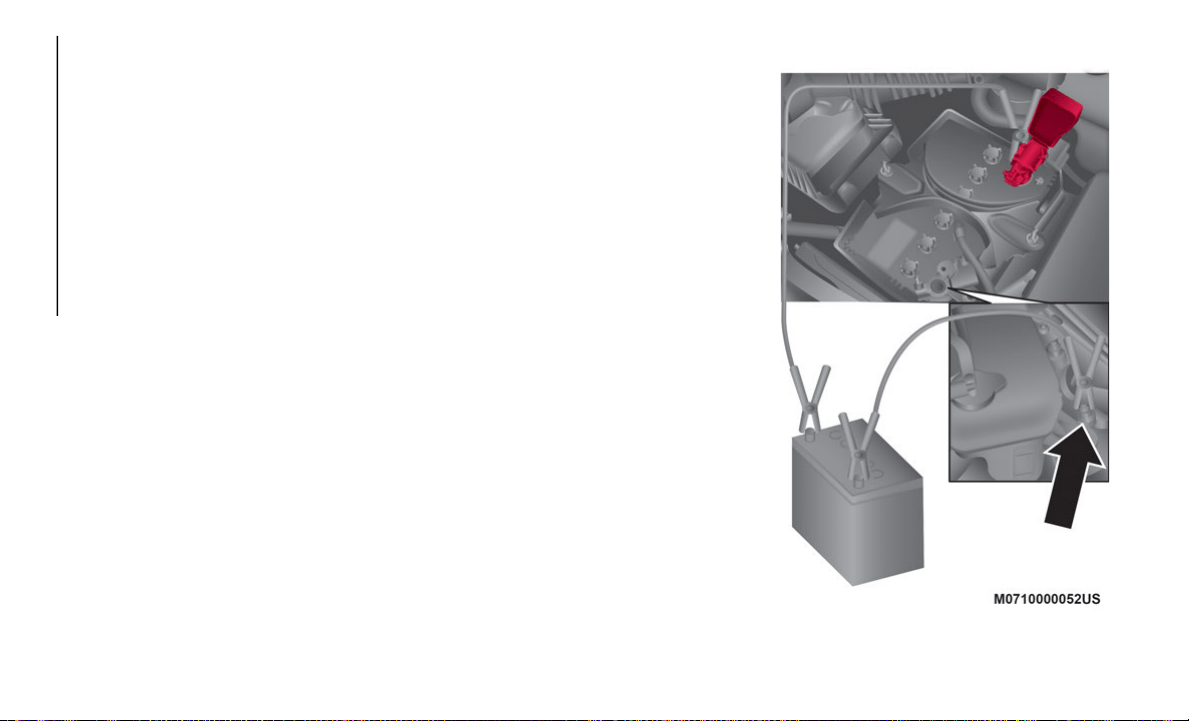
IN CASE OF EMERGENCY
232
If an emergency flat tire repair has been
performed using the Tire Service Kit, FCA
recommends that the tire be replaced with
a new one as soon as possible. If the tire
is to be repaired or reused, contact an
authorized dealer.
The tire can be reused if the sealant
adhering to it is removed. However,
replace the valve with a new one.
Replacing The Bottle
NOTE:
The tire sealant has a period of effective use.
Ch
eck the period of effective use indicated
on the bottle label and do not use it if it has
expired. Have the tire sealant replaced at an
authorized dealer before the period of effec
-
tive use has expired.
Inspect the Tire Service Kit at regular inter-
vals as well as the operation of the tire
c
o
mpressor.
JUMP STARTING
Preparations For Jump Starting
If the battery is discharged, a jump starting
procedure can be performed using the
battery and the cables of another vehicle, or
using a booster battery.
Jump starting is dangerous if done incor-
rectly, so follow the procedure in this section
ca
refully. If you feel unsure about jump
starting, it is strongly recommended that you
have a competent service technician do the
work.
NOTE:
When a booster battery is being used, comply
w
i
th the utilization and precaution instruc-
tions specified by the manufacturer.
Jump Start Locations
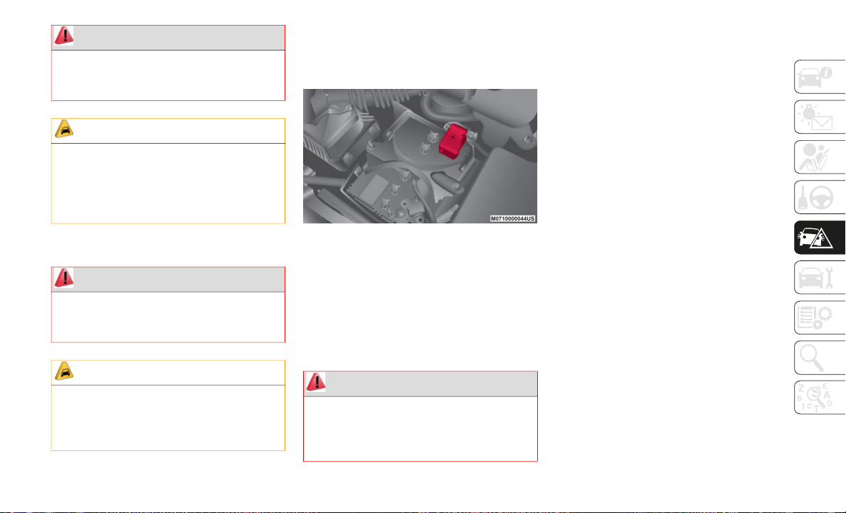
233
Jump Starting Procedure
To jump start the vehicle, follow this proce-
dure:
1. Remove the positive terminal cover.
P
ositive Terminal Cover
2. Make sure the booster battery is 12 Volts
a
nd that the negative terminal is
grounded.
3. Make sure the engine of the vehicle with
t
he booster battery is OFF and all unnec-
essary electrical loads in both vehicles.
4. Connect the positive end of the jumper
c
able to the positive terminal on the
discharged battery.
5. Connect the opposite end of the positive
j
umper cable to the positive terminal on
the booster battery.
6. Connect the negative end of the negative
j
umper cable to the negative terminal of
the booster battery.
7. Connect the opposite end of the negative
j
umper cable to a good engine ground of
the vehicle with the discharged battery
(exposed metal part of the engine) away
from the battery and the fuel injection
system.
8. Start the engine of the booster vehicle
a
nd run it a few minutes. Then start the
engine of the other vehicle.
9. Once the engine is started, remove the
j
umper cables in the reverse sequence.
10.Replace the positive terminal cover.
M
ake sure cover is secure.
WARNING!
Do not attempt jump starting if the battery
is frozen. It could rupture or explode and
cause personal injury.
CAUTION!
Do not use a portable battery booster pack
or any other booster source with a system
voltage greater than 12 Volts or damage to
the battery, starter motor, alternator or
electrical system may occur.
WARNING!
Failure to follow this jump starting
procedure could result in personal injury or
property damage due to battery explosion.
CAUTION!
Failure to follow these procedures could
result in damage to the charging system of
the booster vehicle or the discharged
vehicle.
WARNING!
Do not allow vehicles to touch each other
as this could establish a ground
connection and personal injury could
result.

IN CASE OF EMERGENCY
234
Bump Starting
Never jump start the engine by pushing,
towing or coasting downhill.
NOTE:
You cannot start a vehicle with an auto-
matic transmission by pushing it.
Do not push-start a vehicle that has a
manual transmission. It can damage the
emission control system.
Starting A Flooded Engine
If the engine fails to start, it may be flooded
(excessive fuel in the engine).
Follow this procedure:
1. I
f the engine does not start within 5
s
econds on the first try, wait 10 seconds
and try again.
2. Make sure the parking brake is applied.
3
. Press the accelerator all the way and hold
i
t there.
4. Press the clutch pedal (manual transmis-
s
ion) or the brake pedal (automatic trans-
mission), then push the STOP/START
b
u
tton. If the engine starts, release the
accelerator immediately because the
engine will suddenly rev up.
5. If the engine fails to start, crank it
w
ithout pressing the accelerator.
If the engine still does not start using the
ab
ove procedure, have your vehicle
inspected by an authorized dealer.
IF YOUR ENGINE
OVERHEATS
If Your Engine Overheats
In any of the following situations, you can
reduce the potential for overheating by
taking the appropriate action.
On highways — slow down.
In city traffic — while stopped, place the
transmission in NEUTRAL, but do not
increase engine idle speed.
NOTE:
There are steps that you can take to slow
do
wn an impending overheat condition:
If your Air Conditioner (A/C) is on, turn it
off. The A/C system adds heat to the
engine cooling system and turning the A/C
off can help remove this heat.
You can also turn the temperature control
to maximum heat, the mode control to
floor and the blower control to high. This
allows the heater core to act as a supple
-
ment to the radiator and aids in removing
he
at from the engine cooling system.
WARNING!
You or others can be badly burned by hot
engine coolant (antifreeze) or steam from
your radiator. If you see or hear steam
coming from under the hood, do not open
the hood until the radiator has had time to
cool. Never try to open a cooling system
pressure cap when the radiator or coolant
bottle is hot.
235
If Steam Is Coming From The Engine Compart-
ment:
Do not go near the front of the vehicle. Stop
th
e engine. Wait until the steam dissipates,
then open the hood and start the engine.
If Neither Coolant Nor Steam Is Escaping:
Open the hood and idle the engine until it
co
ols.
NOTE:
If the cooling fan does not operate while
the engine is running, the engine tempera-
ture will increase. Stop the engine and
c
o
ntact an authorized dealer.
If the engine continues to overheat or
frequently overheats, have the cooling
system inspected. The engine could be
seriously damaged unless repairs are
made. Contact an authorized dealer.
TOWING THE VEHICLE
Attaching The Tow Eyes — If Equipped
CAUTION!
Driving with a hot cooling system could
damage your vehicle. If temperature gauge
reads “H”, pull over and stop the vehicle.
Idle the vehicle with the air conditioner
turned off until the pointer drops back into
the normal range. If the pointer remains
on the “H”, turn the engine off
immediately, and call for service.
WARNING!
Stand clear of vehicles when pulling with
tow eyes.
Do not use a chain with a tow eye. Chains
may break, causing serious injury or
death.
Do not use a tow strap with a tow eye.
Tow straps may break or become disen-
gaged, causing serious injury or death.
Failure to follow proper tow eye usage
may cause components to break
resulting in serious injury or death.
CAUTION!
The tow eye must be used exclusively for
roadside assistance operations. Only use
the tow eye with an appropriate device in
accordance with the highway code (a
rigid bar or rope) to flat tow the vehicle
for a short distance to the nearest service
location.
Tow eyes MUST NOT be used to tow
vehicles off the road or where there are
obstacles.
In compliance with the above condi-
tions, towing with a tow eye must take
pl
ace with two vehicles (one towing, the
other towed) aligned as much as possible
along the same center line. Damage to
your vehicle may occur if these guide
-
lines are not followed.
When towing, only use a facility that can
tow vehicles with low ground clearances
as extensive damage can result by using
a standard tow truck platform.
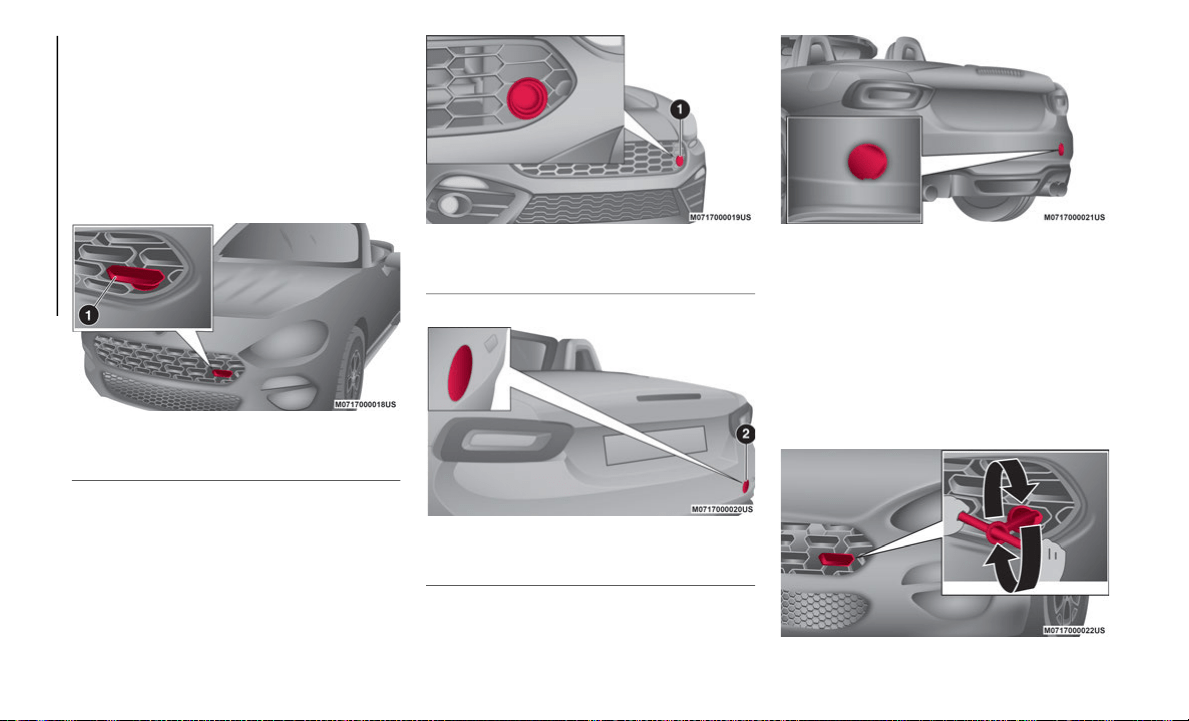
IN CASE OF EMERGENCY
236
Proceed as follows:
1. Remove the towing eyelet and the lug
w
rench from the luggage compartment.
2. Wrap a flathead screwdriver or similar
t
ool with a soft cloth to prevent damage
to a painted bumper, and open the cap
located on the front or rear bumper.
Front Bumper Cap Location
Abarth Front Bumper Cap Location
Rear Bumper Cap Location
Abarth Rear Bumper Cap Location
NOTE:
Do not use excessive force as it may damage
th
e cap or scratch the painted bumper
surface. Remove the cap completely and
store it so as not to lose it.
3. Securely install the tow eye in front or
r
ear using the lug wrench or equivalent.
Installing Front Towing Eye
1— Front Bumper Cap
1— Front Bumper Cap
2— Rear Bumper Cap
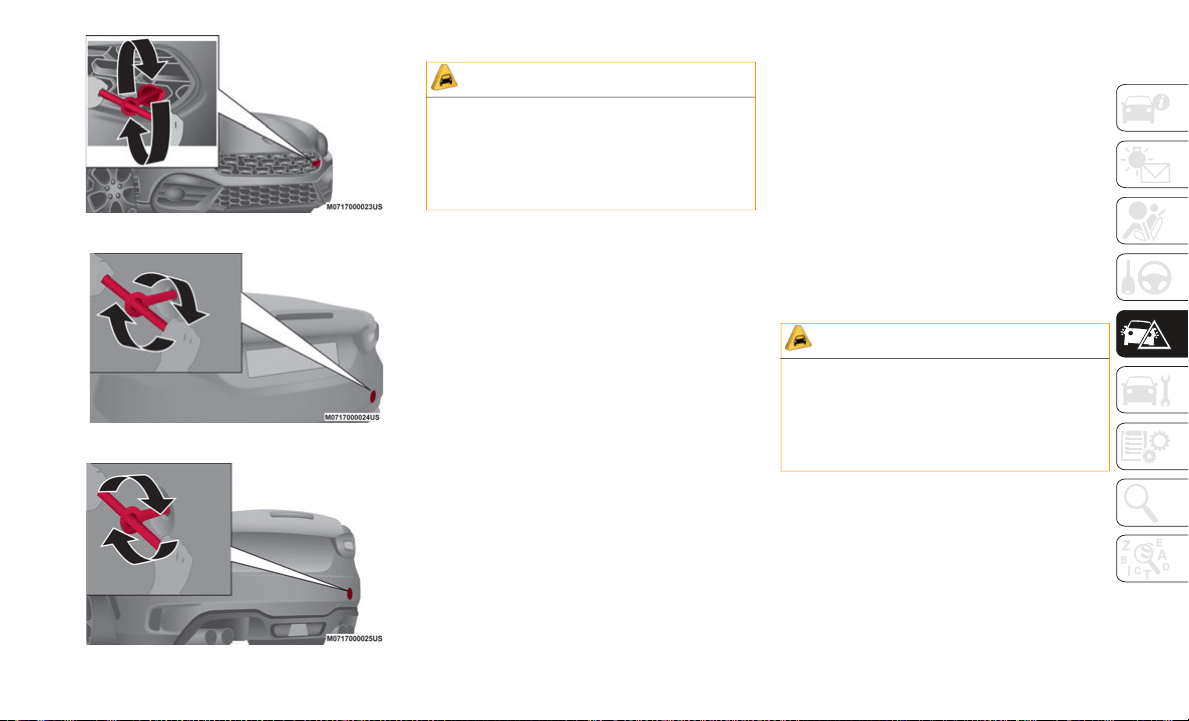
237
Abarth Installing Front Towing Eye
Installing Rear Tow Eye
Abarth Installing Rear Tow Eye
4. H
ook the towing rope to the tow eye.
W
hen using the tow eyes, always pull the
le
ad or chain in a straight direction with
respect to the eyelet. Never apply a sideways
force.
NOTE:
Follow the precautions below to avoid
da
mage to the towing eyelet and towing
hook, vehicle body, or transmission system
when towing:
Do not tow a vehicle heavier than yours.
Do not suddenly accelerate your vehicle as
it will apply a severe shock to the tow eye
and towing hook or rope.
Do not attach any rope other than to the
tow eye and towing hook.
Emergency Towing
Towing Description
Proper lifting and towing are necessary to
pr
event damage to the vehicle. Government
and local laws must be followed.
A towed vehicle usually should have its drive
wh
eels (rear wheels) OFF of the ground. If
excessive damage or other conditions
prevent this, use wheel dollies.
When towing with the rear wheels on the
gr
ound, release the parking brake.
If towing service is not available in an emer-
gency, the vehicle may be towed with all four
w
h
eels on the ground using the towing hook
at the front of the vehicle. Only tow the
vehicle on paved surfaces for short distances
at low speeds.
CAUTION!
Tow eyes are for emergency use only, to
rescue a vehicle stranded off road. Do not
use tow eyes for tow truck hookup or
highway towing. You could damage your
vehicle.
CAUTION!
DO NOT use sling-type equipment when
towing. When securing the vehicle to a
flatbed truck, do not attach to front or rear
suspension components. Damage to your
vehicle may result from improper towing.

IN CASE OF EMERGENCY
238
Follow these instructions when towing the
vehicle with all wheels on the ground:
1. Shift to NEUTRAL for manual transmis-
s
ion or automatic transmission.
2. Cycle the ignition to ACC mode.
3
. Release the parking brake.
N
OTE:
Remember that power assist for the brakes
a
n
d steering will not be available when the
engine is not running.
ENHANCED ACCIDENT
RESPONSE SYSTEM (EARS)
This vehicle is equipped with an Enhanced
Accident Response System.
Please refer to “Constant Monitoring” in
“S
afety” for further information on the
Enhanced Accident Response System
(EARS) function.
EVENT DATA RECORDER
(EDR)
This vehicle is equipped with an Event Data
Recorder (EDR). The main purpose of an
EDR is to record data that will assist in
understanding how a vehicle’s systems
performed under certain crash or near
crash-like situations, such as an air bag
deployment or hitting a road obstacle.
Please refer to “Event Data Recorder (EDR)”
in
“Safety” for further information on the
Event Data Recorder (EDR).

239
SCHEDULED SERVICING
Be extremely careful and prevent injury to
yourself and others or damage to your vehicle
when using this Owner’s Manual for inspec
-
tion and maintenance.
If you are unsure about any procedure it
des
cribes, we strongly urge you to have a reli-
able and qualified service shop perform the
w
or
k, preferably at an authorized dealer.
Factory-trained FCA technicians and genuine
FCA
parts are best for your vehicle. Without
this expertise and the parts that have been
designed and made especially for your
vehicle, inadequate, incomplete, and insuffi
-
cient servicing may result in problems. This
cou
ld lead to vehicle damage or an accident
and injuries.
For expert advice and quality service, contact
an
authorized dealer.
NOTE:
Under no circumstances should oil change
i
nt
ervals exceed 10,000 miles (16,000 kilo-
meters) or 1 year.
To continue New Vehicle Limited Warranty
eli
gibility and to protect your investment, it
is your responsibility to properly maintain
your vehicle according to factory recom
-
mended schedules outlined in this Owner’s
Man
ual. As part of this you must keep your
maintenance records, receipts, repair orders
and any other documents as evidence this
maintenance was performed. You must
present these documents, should any New
Vehicle Limited Warranty coverage disagree
-
ment occur. Failure to do so can result in
you
r New Vehicle Limited Warranty being
voided either in whole or in part.
This evidence may consist of the following:
Original copies of repair orders or other
receipts that include the mileage and date
the vehicle was serviced. Each receipt
should be signed by a qualified automo
-
tive service technician.
For self maintenance, a statement that
you completed the maintenance yourself,
displaying mileage and the date the work
was performed. Also, receipts for the
replacement parts (fluid, filters, etc.) indi
-
cating the date and mileage must accom-
pany this statement.
NOTE:
If you elect to perform maintenance yourself
o
r
have your vehicle serviced at a location
other than an authorized dealer, FCA
requires that all fluids, parts and materials
must meet FCA standards for durability and
performance as described in this Owner’s
Manual.
Claims against the warranty resulting from
lac
k of maintenance, as opposed to defective
materials or authorized FCA workmanship,
will not be honored.
Any auto repair shop using parts equivalent
to
your vehicle's original equipment may
perform maintenance. But we recommend
that it always be done by an authorized
dealer using genuine FCA parts. Selecting
“Maintenance Monitor” enables the system
to notify you of your vehicle's approaching
inspection/servicing period.
Owner Maintenance Precautions
The owner or a qualified service technician
should make these vehicle inspections at the
indicated intervals to ensure safe and
dependable operation.

SERVICING AND MAINTENANCE
240
Bring any problem to the attention of an
authorized dealer or qualified service techni-
cian as soon as possible.
When refueling perform inspection of:
Brake and clutch fluid level
Engine coolant level
Engine oil level
Washer fluid level
At least monthly perform inspection of:
Tire inflation pressures
At least twice a year (for example, every
s
p
ring and fall) perform inspection of:
Engine coolant
Engine oil
As explained in the Introduction paragraph
of
“Scheduled Servicing”, several proce-
dures can be done only by a qualified service
t
e
chnician with special tools.
For details, read the separate Warranty
Bo
oklet provided with the vehicle. If you are
unsure about any servicing or maintenance
procedure, have it done by an authorized
dealer.
There are strict environmental laws regarding
th
e disposal of waste oil and fluids. Please
dispose of your waste properly and with due
regard to the environment.
We recommend that you entrust the oil and
fl
uid changes of your vehicle to an autho-
rized dealer.
Periodic Checks
Every 620 miles (1,000 km) or before long
trips check and, if necessary, top off:
Engine coolant level
Brake fluid level
Windshield washer fluid level
Tire inflation pressure and condition
Operation of lighting system (headlights,
direction indicators, hazard warning
lights, etc.)
Operation of windshield washer/wiper
system and positioning/wear of windshield
wiper blades
Every 1,860
miles (3,000 km) check and top
off the engine oil level if required
Heavy-Duty Use Of The Vehicle
If the vehicle is used under one of the
following conditions:
Dusty roads
Short, repeated trips less than 4.4 -
5 miles (7 - 8 km) at sub-zero outside
te
mperatures
Engine idling for long periods of time or
driving long distances at low speeds or
long periods of inactivity
The following checks must be carried out
mo
re often than indicated in the Scheduled
Servicing Plan:
Check front disc brake pad condition and
wear
Check cleanliness of underhood area and
all door and trunk locks, cleanliness and
lubrication of linkage
Visually inspect conditions of the: engine,
transmission, lines and hoses (exhaust/
fuel system/brakes) and rubber elements
(hoses/belts/etc.)
Check battery charge and battery fluid
level

241
Visually inspect conditions of the acces-
sory drive belts
Check and, if necessary, change engine oil
and replace oil filter
Check and, if necessary, replace cabin air
filter
Check and, if necessary, replace air
cleaner
Severe Duty All Models
Change Engine Oil at 4,000 miles
(6
,500 km) if the vehicle is operated in a
du
sty and off road environment or is oper-
ated predominately at idle or only very low
engine RPM. This type of vehicle use is
considered Severe Duty.

SERVICING AND MAINTENANCE
242
Scheduled Servicing Plan
Mileage or time passed (whichever
comes first)
10,000
20,000
3
0,000
4
0,000
5
0,000
6
0,000
7
0,000
8
0,000
9
0,000
1
00,000
1
10,000
1
20,000
1
30,000
1
40,000
1
50,000
Or Years: 1 2 3 4 5 6 7 8 9 10 11 12 13 14 15
Or Kilometers:
16,000
32,000
4
8,000
6
4,000
8
0,000
9
6,000
1
12,000
1
28,000
1
44,000
1
60,000
1
76,000
1
92,000
2
08,000
2
24,000
2
40,000
Check tire condition/wear and adjust
pressure, if necessary, check Tire
Service Kit expiration date (if
equipped).
• • • • • • • • • • • • • • •
Check operation of lighting system
(
h
eadlamps, direction indicators,
hazard warning lights, luggage
compartment, passenger compartment,
glove compartment, instrument panel
warning lights, etc.).
• • • • • • • • • • • • • • •
Check and, if necessary, top up fluid
le
vels (brakes/hydraulic clutch,
windshield washer, battery, engine
coolant, etc.).
• • • • • • • • • • • • • •
•
Check engine control system operation
(v
ia diagnostic tool).
• • • • • • • • • • • • • • •

243
Visually inspect condition of: exterior
bodywork, underbody protection, pipes
and hoses (exhaust - fuel system -
brakes), rubber elements (boots,
sleeves, bushings, etc.).
• • • • • • •
Visually inspect conditions of steering
el
ements and check their operation.
• • • • • • •
Check the front and rear suspension, tie
ro
ds, CV Joints, and replace if
necessary.
• • • • • • • • • • • • • • •
Check endfloat of wheel bearings.
• •
•
• • • •
Check windshield/rear window wiper
b
l
ade position/wear.
• • • • • • • •
Check operation of windshield washer
sy
stem and adjust jets if necessary.
• • • • • • • •
Check cleanliness of hood and trunk
lo
cks and cleanliness and lubrication of
linkages.
• • • • • • • •
Mileage or time passed (whichever
comes first)
10,000
20,000
30,000
40,000
50,000
60,000
70,000
80,000
90,000
100,000
110,000
120,000
130,000
140,000
150,000
Or Years: 1 2 3 4 5 6 7 8 9 10 11 12 13 14 15
Or Kilometers:
16,000
32,000
48,000
64,000
80,000
96,000
112,000
128,000
144,000
160,000
176,000
192,000
208,000
224,000
240,000

SERVICING AND MAINTENANCE
244
Check parking brake lever travel and
adjust, if necessary.
• • • • • • • • • • • • • • •
Visually check the condition and wear of
th
e front and rear brakes.
• • • • • • • • • • • • • • •
Visually inspect condition of
ev
aporation control system.
• • • • •
Visual inspect the condition and
te
nsioning of the accessory drive belt.
• • •
Replace the accessory drive belt.
1
•
Inspect and replace PCV valve if
ne
cessary.
•
Change engine oil and replace oil filter.
2
In accordance with Oil Change Indicator System OR Severe Duty Mileage, whichever occurs first.
Replace spark plugs (1.4L Turbo
en
gine).
3
• • • • •
Mileage or time passed (whichever
comes first)
10,000
20,000
30,000
40,000
50,000
60,000
70,000
80,000
90,000
100,000
110,000
120,000
130,000
140,000
150,000
Or Years: 1 2 3 4 5 6 7 8 9 10 11 12 13 14 15
Or Kilometers:
16,000
32,000
48,000
64,000
80,000
96,000
112,000
128,000
144,000
160,000
176,000
192,000
208,000
224,000
240,000

245
Replace engine air filter.
4
• • • • •
Flush and replace the engine coolant at
10
years or 150,000 miles
(2
40,000 km) whichever comes first.
• •
Replace the timing belt (1.4L Turbo
En
gine).
•
1. Replace belt every 40,000 miles (60,000 km) for use on dusty roads.
2. The oil and oil filter replacement must be carried out when indicated by a warning light or message on the instrument panel, or in any case should
n
ot exceed one year.
3. The spark plug change is distance based only, yearly intervals do not apply. The following are essential to ensure correct operation and prevent
s
erious damage to the engine:
Only use spark plugs of the same make and type which are specially certified for such engines (refer to “Engine” in “Technical Specifications”
for further information).
Strictly comply with the spark plug replacement interval given in the scheduled servicing plan for spark plug replacement.
Contact an authorized dealer if you have any questions.
4. The engine air cleaner should be inspected at every oil change if used in dusty areas.
Mileage or time passed (whichever
comes first)
10,000
20,000
30,000
40,000
50,000
60,000
70,000
80,000
90,000
100,000
110,000
120,000
130,000
140,000
150,000
Or Years: 1 2 3 4 5 6 7 8 9 10 11 12 13 14 15
Or Kilometers:
16,000
32,000
48,000
64,000
80,000
96,000
112,000
128,000
144,000
160,000
176,000
192,000
208,000
224,000
240,000

SERVICING AND MAINTENANCE
246
WARNING!
You can be badly injured working on or
around a motor vehicle. Do only service
work for which you have the knowledge
and the right equipment. If you have any
doubt about your ability to perform a
service job, take your vehicle to a compe
-
tent mechanic.
Failure to properly inspect and maintain
your vehicle could result in a component
malfunction and effect vehicle handling
and performance. This could cause an
accident.
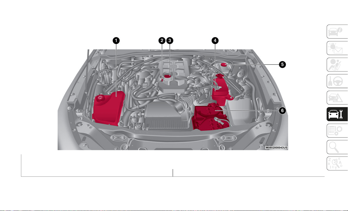
247
ENGINE COMPARTMENT
Checking Levels
1 — Window Washer Reservoir 4 — Engine Coolant Reservoir
2 — Engine Oil Dipstick 5 — Brake/Clutch Fluid Reservoir Cap
3 — Engine Oil Cap 6 — Battery
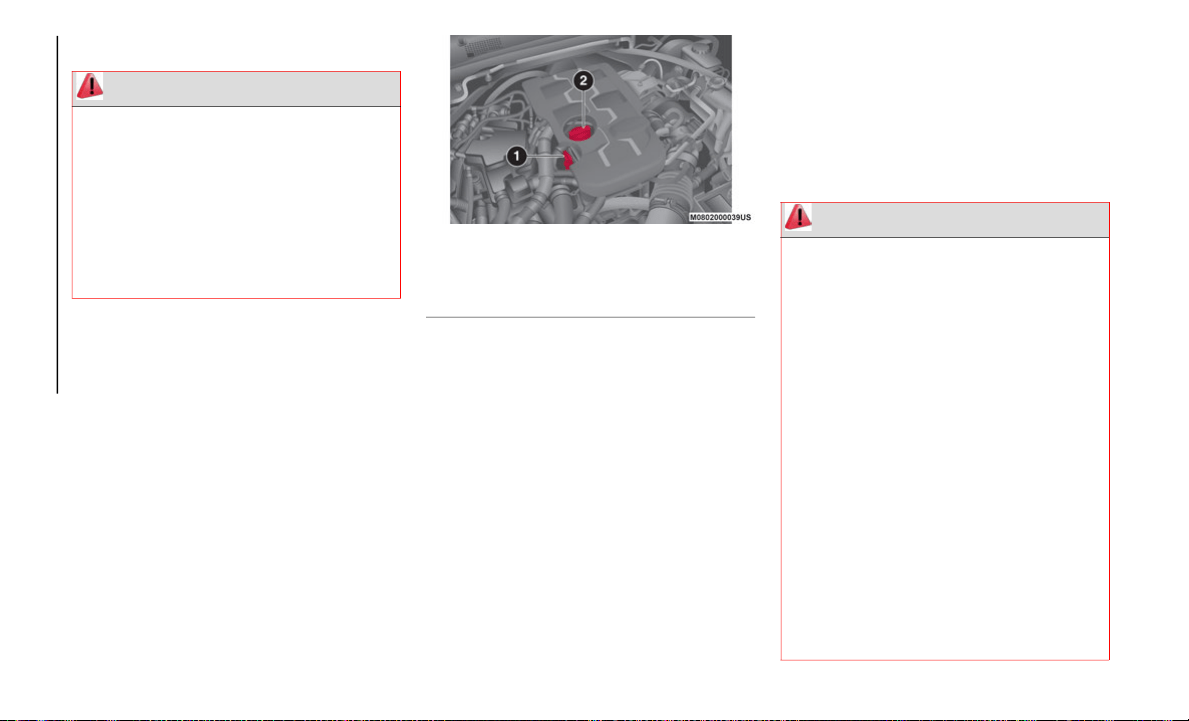
SERVICING AND MAINTENANCE
248
Engine Oil
Recommended Oil
Refer to “Fluids And Lubricants” in “Tech-
nical Specifications” for further information.
Inspecting engine oil level
Proceed as follows:
1. B
e sure the vehicle is on a level surface.
2
. Warm up the engine to normal operating
t
emperature.
3. Turn the engine off and wait at least five
m
inutes for the oil to return to the sump.
4. Pull out the dipstick, wipe it clean, and
r
einsert it fully.
Engine Compartment
5. Pull the dipstick out again and examine
t
he level. The level is normal if it is
between Low and Full. If it is near or
below Low, open the engine oil cap and
add enough oil to bring the level to Full.
NOTE:
Do not overfill the engine oil. This may cause
en
gine damage.
6. Make sure the O-ring on the dipstick is
p
ositioned properly before reinserting the
dipstick.
7. Reinsert the dipstick fully.
E
ngine Oil Consumption
During the initial period of use the engine oil
co
nsumption conditions should stabilize
after the first 3,000 – 3,500
miles (5,000 –
6,
000 km).
Engine Coolant
WARNING!
Be very careful when working in the
engine compartment when the engine is
hot: you may get burned.
Do not get too close to the radiator
cooling fan: the electric fan may start;
danger of injury.
Loose clothing might be pulled by
moving parts.
1 — Engine Oil Dipstick
2 — Engine Oil Cap
WARNING!
You or others can be badly burned by hot
engine coolant (antifreeze) or steam
from your radiator. If you see or hear
steam coming from under the hood, do
not open the hood until the radiator has
had time to cool. Never open a cooling
system pressure cap when the radiator or
coolant bottle is hot.
Keep hands, tools, clothing, and jewelry
away from the radiator cooling fan when
the hood is raised. The fan starts auto
-
matically and may start at any time,
wh
ether the engine is running or not.
When working near the radiator cooling
fan, disconnect the fan motor lead or
turn the ignition to the OFF mode. The
fan is temperature controlled and can
start at any time the ignition is in the ON
mode.
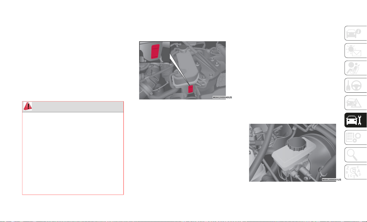
249
Inspecting Coolant Level
NOTE:
Changing the coolant should be done by an
au
thorized dealer.
Inspect the antifreeze protection and coolant
le
vel in the coolant reservoir at least once a
year, at the beginning of the winter season,
and before traveling where temperatures may
drop below freezing.
Inspect the condition and connections of all
co
oling system and heater hoses. Replace
any that are worn or deteriorated.
The coolant should be at full in the radiator
an
d between the F (Full) and L (Low) marks
on the coolant reservoir when the engine is
cool.
Coolant Reservoir
If it is at or near L (Low), add coolant by
mi
xing a minimum solution of 50% Mopar
Long Life Coolant Concentrate for FIAT
Spider. Use higher concentrations (not to
exceed 70%) if temperatures below −34°F
(−37°C) are anticipated. Bring the level to F
(Full). Please contact an authorized dealer
for assistance.
Securely tighten the coolant reservoir tank
ca
p after adding coolant.
If the coolant reservoir is empty or new
co
olant is required frequently, contact an
authorized dealer.
Brake/Clutch Fluid
Inspecting Brake/Clutch Fluid Level
The brakes and clutch draw fluid from the
same reservoir.
Inspect the fluid level in the reservoir
regularly.
It should be kept between the MAX and
MIN lines.
The level normally drops with accumu-
lated use, a condition associated with
we
ar of brake and clutch linings. If it is
excessively low, have the brake/clutch
system inspected. Contact an authorized
dealer.
Brake Fluid Reservoir
WARNING!
Do not open hot engine cooling system.
Never add engine coolant (antifreeze)
when the engine is overheated. Do not
loosen or remove the cap to cool an over
-
heated engine. Heat causes pressure to
bu
ild up in the cooling system. To
prevent scalding or injury, do not remove
the pressure cap while the system is hot
or under pressure.
Do not use a pressure cap other than the
one specified for your vehicle. Personal
injury or engine damage may result.

SERVICING AND MAINTENANCE
250
(Continued)
Windshield And Headlight Washer Fluid
Inspecting Washer Fluid Level
Inspect fluid level in the washer fluid reser-
voir, open the cap and add fluid if necessary.
Windshield Washer Fluid Reservoir
Use plain water if washer fluid is unavail-
able. But use only washer fluid in cold
w
e
ather to prevent it from freezing.
Automatic Transmission Control Unit
The transmission oil level should only be
checked at an authorized dealer.
WARNING!
Use only manufacturer's recommended
brake fluid. Refer to “Fluids And Lubri-
cants” in “Technical Specifications” for
f
u
rther information. Using the wrong
type of brake fluid can severely damage
your brake system and/or impair its
performance. The proper type of brake
fluid for your vehicle is also identified on
the original factory installed hydraulic
master cylinder reservoir.
To avoid contamination from foreign
matter or moisture, use only new brake
fluid or fluid that has been in a tightly
closed container. Keep the master
cylinder reservoir cap secured at all
times. Brake fluid in a open container
absorbs moisture from the air resulting
in a lower boiling point. This may cause
it to boil unexpectedly during hard or
prolonged braking, resulting in sudden
brake failure. This could result in a colli
-
sion.
Overfilling the brake fluid reservoir can
result in spilling brake fluid on hot
engine parts, causing the brake fluid to
catch fire. Brake fluid can also damage
painted and vinyl surfaces, care should
be taken to avoid its contact with these
surfaces.
Do not allow petroleum based fluid to
contaminate the brake fluid. Brake seal
components could be damaged, causing
partial or complete brake failure. This
could result in a collision.
WARNING! (Continued)
251
(Continued)
Battery Maintenance
To get the best service from a battery:
Keep it securely mounted.
Keep the top clean and dry.
Keep terminals and connections clean,
tight, and coated with petroleum jelly or
terminal grease.
Rinse off spilled electrolyte immediately
with a solution of water and baking soda.
If the vehicle will not be used for an
extended time, disconnect the battery
leads and charge the battery every six
weeks.
Battery Replacement
Contact an authorized dealer to purchase a
re
placement battery.
Pressure Washing
BATTERY RECHARGING
Battery Charging Procedure
WARNING!
Battery fluid is a corrosive acid solution
and can burn or even blind you. Do not
allow battery fluid to contact your eyes,
skin, or clothing. Do not lean over a
battery when attaching clamps. If acid
splashes in eyes or on skin, flush the
area immediately with large amounts of
water. Refer to “Jump Starting Proce
-
dure” in “In Case Of Emergency” for
fu
rther information.
Battery gas is flammable and explosive.
Keep flame or sparks away from the
battery. Do not use a booster battery or
any other booster source with an output
greater than 12 Volts. Do not allow cable
clamps to touch each other.
Battery posts, terminals, and related
accessories contain lead and lead
compounds. Wash hands after handling.
CAUTION!
Cleaning the engine compartment with a
high pressure washer is not recommended.
Precautions have been taken to safeguard
all parts and connections however, the
pressures generated by these machines is
such that complete protection against
water ingress cannot be guaranteed.
WARNING!
Battery fluid is a corrosive acid solution
and can burn or even blind you. Do not
allow battery fluid to contact your eyes,
skin, or clothing. Do not lean over a
battery when attaching clamps. If acid
splashes in eyes or on skin, flush the
area immediately with large amounts of
water. Refer to “Jump Starting Proce
-
dure” in “In Case Of Emergency” for
fu
rther information.

SERVICING AND MAINTENANCE
252
Charge battery as follows:
Before recharging the battery, turn off all
accessories and turn the engine off by
placing the ignition in the OFF position.
Disconnect the negative battery cable.
Connect the charger cables to the battery
terminals, observing the polarity (+/–).
Turn on the charger.
When finished, turn the charger off before
disconnecting the battery.
Reconnect the negative battery terminal.
MAINTENANCE
PROCEDURES
The following pages contain instructions on
the required maintenance from the technical
personnel who designed the vehicle.
In addition to these specific maintenance
in
structions specified for routine scheduled
servicing, there are other components which
may require periodic maintenance or
replacement over the vehicle’s life cycle.
Body Lubrication
Ensure that the locks and bodywork junction
points, including components such as the
seat guides, door hinges (and rollers), trunk
and hood are periodically lubricated with
lithium based grease to ensure correct, silent
operation and to protect them from rust and
wear.
Thoroughly clean the components, elimi-
nating every trace of dirt and dust. After
lu
bricating, eliminate excess oil and grease.
Also pay particular attention to the hood
closing devices, to ensure correct operation.
During operations on the hood, be sure to
pe
rform with the engine cold, also remember
to check, clean and lubricate the locking,
release and safety devices.
Make sure the hood's secondary latch keeps
th
e hood from opening when the primary
latch is released.
Lubricate the external lock cylinders twice a
ye
ar. Apply a small amount of high-quality
lubricant directly into the lock cylinder. If
necessary, contact your authorized dealer.
Battery gas is flammable and explosive.
Keep flame or sparks away from the
battery. Do not use a booster battery or
any other booster source with an output
greater than 12 Volts. Do not allow cable
clamps to touch each other.
Battery posts, terminals, and related
accessories contain lead and lead
compounds. Wash hands after handling.
CAUTION!
It is essential when replacing the cables
on the battery that the positive cable is
attached to the positive post and the
negative cable is attached to the nega
-
tive post. Battery posts are marked posi-
tive (+) and negative (-) and are
id
entified on the battery case. Cable
clamps should be tight on the terminal
posts and free of corrosion.
If a “fast charger” is used while the
battery is in the vehicle, disconnect both
vehicle battery cables before connecting
the charger to the battery. Do not use a
“fast charger” to provide starting
voltage.
WARNING! (Continued)
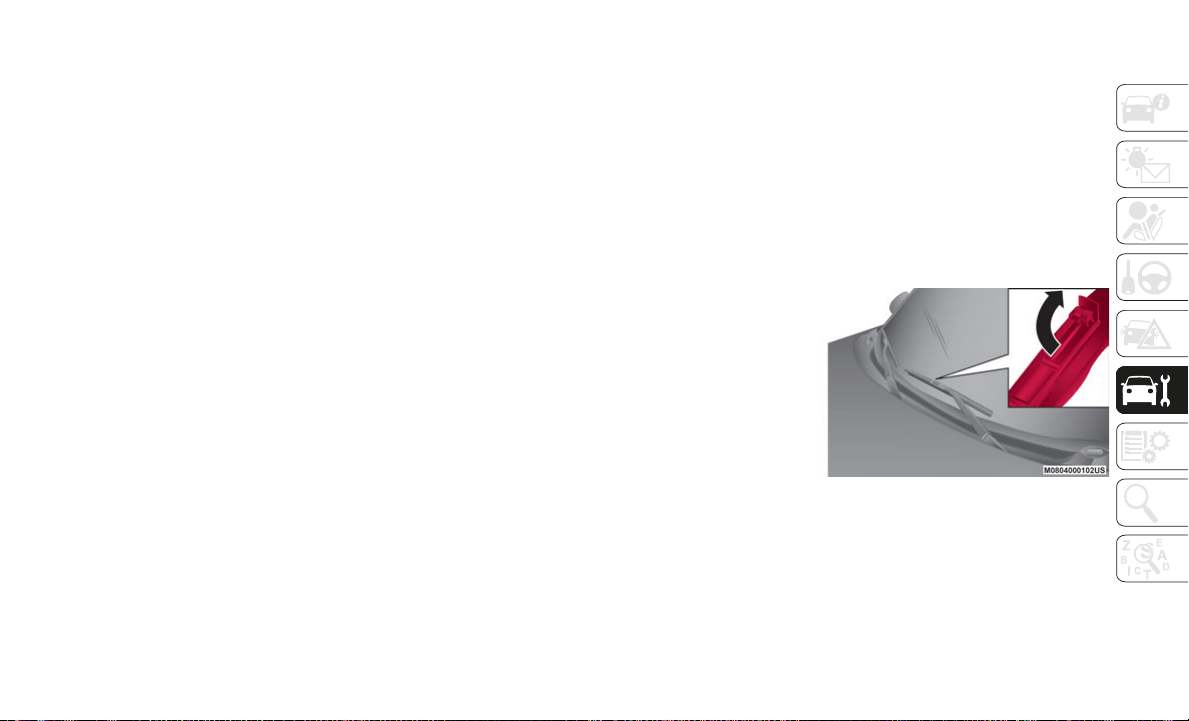
253
Wiper Blades
Contamination of either the windshield or
the blades with foreign matter can reduce
wiper effectiveness. Common sources are
insects, tree sap, and hot wax treatments
used by some commercial car washes.
If the blades are not wiping properly, clean
th
e window and blades with a good cleaner or
mild detergent; then rinse thoroughly with
clean water. Repeat if necessary.
When the wiper lever is in the AUTO position
an
d the ignition is cycled to the ON mode,
the wipers may move automatically in the
following cases:
If the windshield above the rain sensor is
touched.
If the windshield above the rain sensor is
wiped with a cloth.
If the windshield is struck with a hand or
other object.
If the rain sensor is struck with a hand or
other object from inside the vehicle.
NOTE:
Hot waxes applied by automatic car
washers have been known to affect the
wiper's ability to clean windows.
To prevent damage to the wiper blades, do
not use gas, paraffin, paint thinner, or
other solvents on or near them.
Be careful not to pinch hands or fingers as
it may cause injury, or damage the wipers.
When washing or servicing the vehicle,
make sure the wiper lever is in the OFF
position.
Replacing Windshield Wiper Blades
When the wipers no longer clean well, the
bl
ades are probably worn or cracked and
should be replaced.
When raising both windshield wiper arms,
ra
ise the driver's side wiper arm first.
When lowering the wiper arms, slowly lower
th
e wiper arm from the passenger's side first
while supporting it with your hand. Forcefully
lowering the wiper arms could damage the
wiper arm and blade, and may scratch or
crack the windshield.
NOTE:
To prevent damage to the wiper arms and
ot
her components, do not try to sweep the
wiper arm by hand.
Blade Replacement
Proceed as follows:
1. Raise the wiper arm.
2
. Open the clip and slide the blade
a
ssembly in the direction of the arrow.
Clip
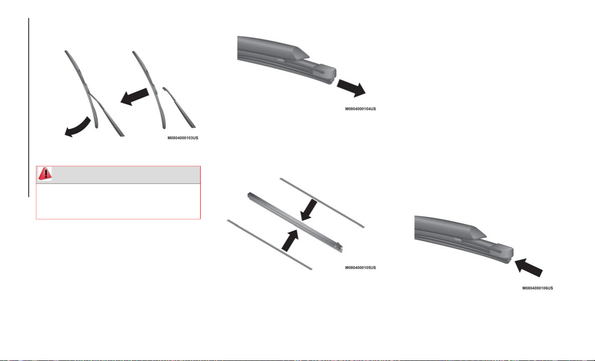
SERVICING AND MAINTENANCE
254
3. Tilt the blade assembly and remove it
from the arm.
Blade Assembly and Arm
4. Pull down the blade rubber and slide it
o
ut of blade holder.
Blade Holder
5. Remove the metal stiffeners from each
b
lade rubber and install them in the new
blade.
Metal Stiffeners
NOTE:
Do not bend or discard the stiffeners, they
will be reused.
If the metal stiffeners are switched, the
blade's wiping efficiency could be
reduced. Do not use the driver's side metal
stiffeners on the passenger's side, or vice
versa.
Be sure to reinstall the metal stiffeners in
the new blade rubber so that the curve is
the same as it was in the old blade rubber.
6. Carefully insert the new blade rubber.
T
hen install the blade assembly in the
reverse order of removal.
Reassemble Blade
WARNING!
To prevent damage to the windshield let
the wiper arm down easily, do not let it
slap down on the windshield.

255
RAISING THE VEHICLE
If the vehicle needs to be raised, see an
authorized dealer which is equipped with
arm hoists or workshop lifts.
The vehicle’s lifting points are marked on the
si
de skirts with the symbols.
WHEELS AND TIRES
Tire Safety Information
Tire safety information will cover aspects of
the following information: Tire Markings, Tire
Identification Numbers, Tire Terminology
and Definitions, Tire Pressures, and Tire
Loading.
Tire Markings
Tire Markings
NOTE:
P (Passenger) — Metric tire sizing is
based on US design standards. P-Metric
tires have the letter “P” molded into the
sidewall preceding the size designation.
Example: P215/65R15 95H.
European — Metric tire sizing is based on
European design standards. Tires
designed to this standard have the tire size
molded into the sidewall beginning with
the section width. The letter "P" is absent
from this tire size designation. Example:
215/65R15 96H.
LT (Light Truck) — Metric tire sizing is
based on US design standards. The size
designation for LT-Metric tires is the same
as for P-Metric tires except for the letters
“LT” that are molded into the sidewall
preceding the size designation. Example:
LT235/85R16.
Temporary spare tires are designed for
temporary emergency use only. Temporary
high pressure compact spare tires have
the letter “T” or “S” molded into the side
-
wall preceding the size designation.
Ex
ample: T145/80D18 103M.
High flotation tire sizing is based on US
design standards and it begins with the
tire diameter molded into the sidewall.
Example: 31x10.5 R15 LT.
1 — US DOT Safety Standards Code
(TIN)
2 — Size Designation
3 — Service Description
4 — Maximum Load
5 — Maximum Pressure
6 — Treadwear, Traction and Tem-
perature Grades

SERVICING AND MAINTENANCE
256
Tire Sizing Chart
EXAMPLE:
Example Size Designation: P215/65R15XL 95H, 215/65R15 96H, LT235/85R16C, T145/80D18 103M, 31x10.5 R15 LT
P = Passenger car tire size based on US design standards, or
"....blank...."
=
Passenger car tire based on European design standards, or
LT = Light truck tire based on US design standards, or
T
or S = Temporary spare tire or
3
1 = Overall diameter in inches (in)
2
15, 235, 145 =
Section width in millimeters (mm)
65, 85, 80 = Aspect ratio in percent (%)
Ratio of section height to section width of tire, or
10.5 = Section width in inches (in)
R
= Construction code
"R" means radial construction, or
"D" means diagonal or bias construction
15, 16, 18 = Rim diameter in inches (in)
S
ervice Description:
95
= Load Index
A numerical code associated with the maximum load a tire can carry
H = Speed Symbol
A symbol indicating the range of speeds at which a tire can carry a load corresponding to its load index under certain operating conditions
The maximum speed corresponding to the speed symbol should only be achieved under specified operating conditions (i.e., tire pressure,
vehicle loading, road conditions, and posted speed limits)

257
Tire Identification Number (TIN)
The TIN may be found on one or both sides of the tire; however, the date code may only be on one side. Tires with white sidewalls will have
the full TIN, including the date code, located on the white sidewall side of the tire. Look for the TIN on the outboard side of black sidewall
tires as mounted on the vehicle. If the TIN is not found on the outboard side, then you will find it on the inboard side of the tire.
Load Identification:
Absence of the following load identification symbols on the sidewall of the tire indicates a Standard Load (SL) tire:
XL = Extra load (or reinforced) tire, or
LL = Light load tire or
C, D, E, F, G = Load range associated with the maximum load a tire can carry at a specified pressure
Maximum Load –
Maximum load indicates the maximum load this tire is designed to carry
Maximum Pressure –
Maximum pressure indicates the maximum permissible cold tire inflation pressure for this tire
EXAMPLE:
EXAMPLE:
DOT MA L9 ABCD 0301
DOT = Department of Transportation
This symbol certifies that the tire is in compliance with the US Department of Transportation tire safety standards and is approved for
highway use
MA = Code representing the tire manufacturing location (two digits)
L
9 = Code representing the tire size (two digits)
A
BCD = Code used by the tire manufacturer (one to four digits)

SERVICING AND MAINTENANCE
258
Tire Terminology And Definitions
03 = Number representing the week in which the tire was manufactured (two digits)
03 means the 3rd week
01 = Number representing the year in which the tire was manufactured (two digits)
01 means the year 2001
Prior to July 2000, tire manufacturers were only required to have one number to represent the year in which the tire was manufactured.
Example: 031 could represent the 3rd week of 1981 or 1991
Term Definition
B-Pillar The vehicle B-Pillar is the structural member of the body located behind the front
door.
Cold Tire Inflation Pressure Cold tire inflation pressure is defined as the tire pressure after the vehicle has not
be
en driven for at least three hours, or driven less than 1 mile (1.6 km) after
si
tting for a minimum of three hours. Inflation pressure is measured in units of
PSI (pounds per square inch) or kPa (kilopascals).
Maximum Inflation Pressure The maximum inflation pressure is the maximum permissible cold tire inflation
pr
essure for this tire. The maximum inflation pressure is molded into the sidewall.
Recommended Cold Tire Inflation Pressure Vehicle manufacturer's recommended cold tire inflation pressure as shown on the
ti
re placard.
Tire Placard A label permanently attached to the vehicle describing the vehicle’s loading
ca
pacity, the original equipment tire sizes and the recommended cold tire
inflation pressures.
EXAMPLE:
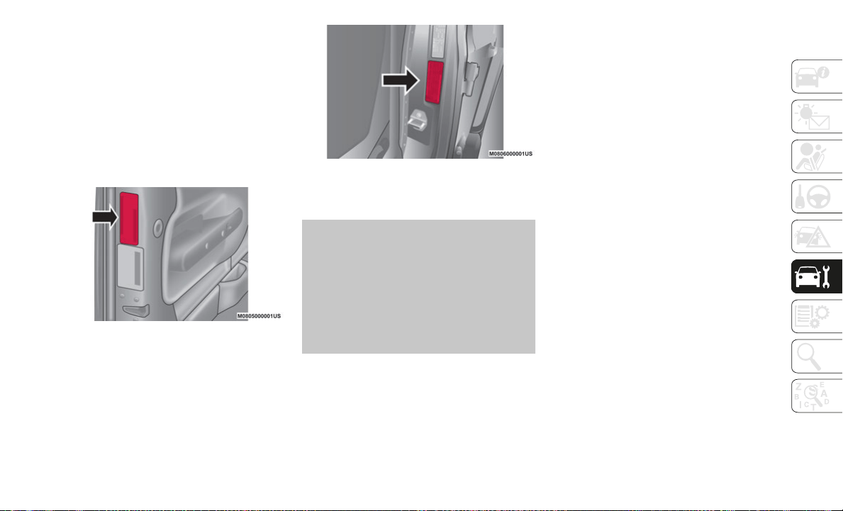
259
Tire Loading And Tire Pressure
NOTE:
The proper cold tire inflation pressure is
li
sted on the driver’s side B-Pillar or the rear
edge of the driver's side door.
Check the inflation pressure of each tire,
in
cluding the spare tire (if equipped), at
least monthly and inflate to the recom
-
mended pressure for your vehicle.
Example Tire Placard Location (Door)
Example Tire Placard Location (B-Pillar)
Tire And Loading Information Placard
Tire And Loading Information Placard
This placard tells you important information
a
b
out the:
1. Number of people that can be carried in
t
he vehicle.
2. Total weight your vehicle can carry.
3
. Tire size designed for your vehicle.
4
. Cold tire inflation pressures for the front,
r
ear, and spare tires.
Loading
The vehicle maximum load on the tire must
not exceed the load carrying capacity of the
tire on your vehicle. You will not exceed the
tire's load carrying capacity if you adhere to
the loading conditions, tire size, and cold tire
inflation pressures specified on the Tire and
Loading Information placard in “Vehicle
Loading” in the “Starting And Operating”
section of this manual.

SERVICING AND MAINTENANCE
260
NOTE:
Under a maximum loaded vehicle condition,
gr
oss axle weight ratings (GAWRs) for the
front and rear axles must not be exceeded.
For further information on GAWRs, vehicle
lo
ading, and trailer towing, refer to “Vehicle
Loading” in the “Starting And Operating”
section of this manual.
To determine the maximum loading condi-
tions of your vehicle, locate the statement
“T
he combined weight of occupants and
cargo should never exceed XXX kg or XXX
lbs” on the Tire and Loading Information
placard. The combined weight of occupants,
cargo/luggage and trailer tongue weight (if
applicable) should never exceed the weight
referenced here.
Steps For Determining Correct Load
Limit—
(1) Locate the statement “The
co
mbined weight of occupants and
cargo should never exceed XXX kg or
XXX lbs.” on your vehicle's placard.
(2) Determine the combined weight of
th
e driver and passengers that will be
riding in your vehicle.
(3) Subtract the combined weight of
th
e driver and passengers from XXX kg
or XXX lbs.
(4) The resulting figure equals the
av
ailable amount of cargo and luggage
load capacity. For example, if “XXX”
amount equals 1400 lbs. and there
will be five 150 lb passengers in your
vehicle, the amount of available cargo
and luggage load capacity is 650 lbs.
(1400-750 (5x150) = 650 lbs.)
(5) Determine the combined weight of
lu
ggage and cargo being loaded on the
vehicle. That weight may not safely
exceed the available cargo and
luggage load capacity calculated in
Step 4.
(6) If your vehicle will be towing a
tr
ailer, load from your trailer will be
transferred to your vehicle. Consult
this manual to determine how this
reduces the available cargo and
luggage load capacity of your vehicle.
Metric Example For Load Limit
For example, if “XXX” amount equals 635 kg
an
d there will be five 68 kg passengers in your
vehicle, the amount of available cargo and
luggage load capacity is 295 kg (635-340
(5x68) = 295 kg) as shown in step 4.
NOTE:
If your vehicle will be towing a trailer, load
from your trailer will be transferred to your
vehicle. The following table shows exam
-
ples on how to calculate total load, cargo/
lu
ggage, and towing capacities of your
vehicle with varying seating configurations
and number and size of occupants. This
table is for illustration purposes only and
may not be accurate for the seating and
load carry capacity of your vehicle.
For the following example, the combined
weight of occupants and cargo should
never exceed 865 lbs (392 kg).

261
Tires — General Information
Tire Pressure
Proper tire inflation pressure is essential to
the safe and satisfactory operation of your
vehicle. Four primary areas are affected by
improper tire pressure:
Safety
Fuel Economy
Tread Wear
Ride Comfort And Vehicle Stability
WARNING!
Overloading of your tires is dangerous.
Overloading can cause tire failure, affect
vehicle handling, and increase your
stopping distance. Use tires of the
recommended load capacity for your
vehicle. Never overload them.

SERVICING AND MAINTENANCE
262
Safety Both underinflation and overinflation affect
the stability of the vehicle and can produce
a feeling of sluggish response or over respon
-
siveness in the steering.
NOTE:
Unequal tire pressures from side to side
may cause erratic and unpredictable
steering response.
Unequal tire pressure from side to side
may cause the vehicle to drift left or right.
Fuel Economy
Underinflated tires will increase tire rolling
r
e
sistance resulting in higher fuel consump-
tion.
Tread Wear
Improper cold tire inflation pressures can
c
a
use abnormal wear patterns and reduced
tread life, resulting in the need for earlier tire
replacement.
Ride Comfort And Vehicle Stability
Proper tire inflation contributes to a comfort-
able ride. Overinflation produces a jarring
an
d uncomfortable ride.
Tire Inflation Pressures
The proper cold tire inflation pressure is
listed on the driver's side B-Pillar or rear
edge of the driver's side door.
At least once a month:
Check and adjust tire pressure with a good
quality pocket-type pressure gauge. Do not
make a visual judgement when deter
-
mining proper inflation. Tires may look
pr
operly inflated even when they are
under-inflated.
Inspect tires for signs of tire wear or visible
damage.
Inflation pressures specified on the placard
ar
e always “cold tire inflation pressure”.
Cold tire inflation pressure is defined as the
tire pressure after the vehicle has not been
driven for at least three hours, or driven less
than 1
mile (1.6 km) after sitting for a
WARNING!
Improperly inflated tires are dangerous
and can cause collisions.
Underinflation increases tire flexing and
can result in overheating and tire failure.
Overinflation reduces a tire's ability to
cushion shock. Objects on the road and
chuckholes can cause damage that
result in tire failure.
Overinflated or underinflated tires can
affect vehicle handling and can fail
suddenly, resulting in loss of vehicle
control.
Unequal tire pressures can cause
steering problems. You could lose
control of your vehicle.
Unequal tire pressures from one side of
the vehicle to the other can cause the
vehicle to drift to the right or left.
Always drive with each tire inflated to the
recommended cold tire inflation pres-
sure.
CAUTION!
After inspecting or adjusting the tire
pressure, always reinstall the valve stem
cap. This will prevent moisture and dirt
from entering the valve stem, which could
damage the valve stem.
263
minimum of three hours. The cold tire infla-
tion pressure must not exceed the maximum
in
flation pressure molded into the tire side-
wall.
Check tire pressures more often if subject to
a
wide range of outdoor temperatures, as tire
pressures vary with temperature changes.
Tire pressures change by approximately 1 psi
(7
kPa) per 12°F (7°C) of air temperature
change. Keep this in mind when checking
tire pressure inside a garage, especially in
the Winter.
Example: If garage temperature = 68°F
(2
0°C) and the outside temperature = 32°F
(0°C) then the cold tire inflation pressure
should be increased by 3 psi (21 kPa), which
equals 1 psi (7 kPa) for every 12°F (7°C) for
this outside temperature condition.
Tire pressure may increase from 2 to 6 psi
(1
3 to 40 kPa) during operation. DO NOT
reduce this normal pressure build up or your
tire pressure will be too low.
Tire Pressures For High Speed Operation
The manufacturer advocates driving at safe
speeds and within posted speed limits.
Where speed limits or conditions are such
that the vehicle can be driven at high speeds,
maintaining correct tire inflation pressure is
very important. Increased tire pressure and
reduced vehicle loading may be required for
high-speed vehicle operation. Refer to an
authorized tire dealer or original equipment
vehicle dealer for recommended safe oper
-
ating speeds, loading and cold tire inflation
p
r
essures.
Radial Ply Tires
Tire Repair
If your tire becomes damaged, it may be
re
paired if it meets the following criteria:
The tire has not been driven on when flat.
The damage is only on the tread section of
your tire (sidewall damage is not repair-
able).
The puncture is no greater than a ¼ of an
inch (6 mm).
Consult an authorized tire dealer for tire
re
pairs and additional information.
Damaged Run Flat tires, or Run Flat tires
th
at have experienced a loss of pressure
should be replaced immediately with another
Run Flat tire of identical size and service
description (Load Index and Speed Symbol).
Run Flat Tires — If Equipped
Run Flat tires allow you the capability to
drive 50 miles (80 km) at 50 mph (80 km/h)
af
ter a rapid loss of inflation pressure. This
rapid loss of inflation is referred to as the
Run Flat mode. A Run Flat mode occurs
when the tire inflation pressure is of/or below
14 psi (96 kPa). Once a Run Flat tire reaches
WARNING!
High speed driving with your vehicle under
maximum load is dangerous. The added
strain on your tires could cause them to
fail. You could have a serious collision. Do
not drive a vehicle loaded to the maximum
capacity at continuous speeds above
75
mph (120 km/h).
WARNING!
Combining radial ply tires with other types
of tires on your vehicle will cause your
vehicle to handle poorly. The instability
could cause a collision. Always use radial
ply tires in sets of four. Never combine
them with other types of tires.
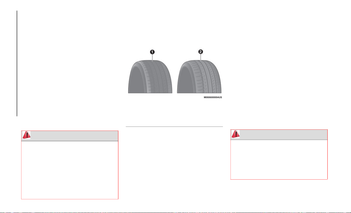
SERVICING AND MAINTENANCE
264
the run flat mode it has limited driving capa-
bilities and needs to be replaced immedi-
ately. A Run Flat tire is not repairable.
NOTE:
TPM Sensor must be replaced after driving
t
h
e vehicle on a flat tire condition.
It is not recommended driving a vehicle
lo
aded at full capacity or to tow a trailer
while a tire is in the run flat mode.
See the tire pressure monitoring section for
mo
re information.
Tire Spinning
When stuck in mud, sand, snow, or ice
conditions, do not spin your vehicle's wheels
above 30
mph (48 km/h) or for longer than
30
seconds continuously without stopping.
Tread Wear Indicators
Tread wear indicators are in the original
equipment tires to help you in determining
when your tires should be replaced.
Tire Tread
These indicators are molded into the bottom
of
the tread grooves. They will appear as
bands when the tread depth becomes a 1/16
of an inch (1.6
mm). When the tread is worn
to
the tread wear indicators, the tire should
be replaced.
Refer to “Replacement Tires” in this section
fo
r further information.
Life Of Tire
The service life of a tire is dependent upon
varying factors including, but not limited to:
Driving style.
Tire pressure - Improper cold tire inflation
pressures can cause uneven wear patterns
to develop across the tire tread. These
abnormal wear patterns will reduce tread
life, resulting in the need for earlier tire
replacement.
Distance driven.
Performance tires, tires with a speed
rating of V or higher, and Summer tires
typically have a reduced tread life. Rota
-
tion of these tires per the vehicle sched-
uled maintenance is highly recommended.
WARNING!
Fast spinning tires can be dangerous.
Forces generated by excessive wheel
speeds may cause tire damage or failure. A
tire could explode and injure someone. Do
not spin your vehicle's wheels faster than
30
mph (48 km/h) for more than 30
se
conds continuously when you are stuck,
and do not let anyone near a spinning
wheel, no matter what the speed.
1 — Worn Tire
2 — New Tire
WARNING!
Tires and the spare tire should be replaced
after six years, regardless of the remaining
tread. Failure to follow this warning can
result in sudden tire failure. You could lose
control and have a collision resulting in
serious injury or death.
265
(Continued)
NOTE:
Wheel Valve Stem must be replaced as well
wh
en installing new tires due to wear and
tear in existing tires.
Keep dismounted tires in a cool, dry place
wi
th as little exposure to light as possible.
Protect tires from contact with oil, grease,
and gasoline.
Replacement Tires
The tires on your new vehicle provide a
balance of many characteristics. They should
be inspected regularly for wear and correct
cold tire inflation pressures. The manufac
-
turer strongly recommends that you use tires
eq
uivalent to the originals in size, quality
and performance when replacement is
needed. Refer to the paragraph on “Tread
Wear Indicators” in this section. Refer to the
Tire and Loading Information placard or the
Vehicle Certification Label for the size desig
-
nation of your tire. The Load Index and
Sp
eed Symbol for your tire will be found on
the original equipment tire sidewall.
See the Tire Sizing Chart example found in
th
e “Tire Safety Information” section of this
manual for more information relating to the
Load Index and Speed Symbol of a tire.
It is recommended to replace the two front
ti
res or two rear tires as a pair. Replacing just
one tire can seriously affect your vehicle’s
handling. If you ever replace a wheel, make
sure that the wheel’s specifications match
those of the original wheels.
It is recommended you contact an authorized
ti
re dealer or original equipment dealer with
any questions you may have on tire specifica
-
tions or capability. Failure to use equivalent
re
placement tires may adversely affect the
safety, handling, and ride of your vehicle.
Tire Types
All Season Tires — If Equipped
All Season tires provide traction for all
seasons (Spring, Summer, Autumn, and
Winter). Traction levels may vary between
different all season tires. All season tires can
be identified by the M+S, M&S, M/S or MS
designation on the tire sidewall. Use all
WARNING!
Do not use a tire, wheel size, load rating,
or speed rating other than that specified
for your vehicle. Some combinations of
unapproved tires and wheels may change
suspension dimensions and performance
characteristics, resulting in changes to
steering, handling, and braking of your
vehicle. This can cause unpredictable
handling and stress to steering and
suspension components. You could lose
control and have a collision resulting in
serious injury or death. Use only the tire
and wheel sizes with load ratings
approved for your vehicle.
Never use a tire with a smaller load index
or capacity, other than what was origi-
nally equipped on your vehicle. Using a
t
i
re with a smaller load index could result
in tire overloading and failure. You could
lose control and have a collision.
Failure to equip your vehicle with tires
having adequate speed capability can
result in sudden tire failure and loss of
vehicle control.
CAUTION!
Replacing original tires with tires of a
different size may result in false
speedometer and odometer readings.
WARNING! (Continued)
SERVICING AND MAINTENANCE
266
season tires only in sets of four; failure to do
so may adversely affect the safety and
handling of your vehicle.
Summer Or Three Season Tires — If
Equipped
Summer tires provide traction in both wet
and dry conditions, and are not intended to
be driven in snow or on ice. If your vehicle is
equipped with Summer tires, be aware these
tires are not designed for Winter or cold
driving conditions. Install Winter tires on
your vehicle when ambient temperatures are
less than 40°F (5°C) or if roads are covered
with ice or snow. For more information,
contact an authorized dealer.
Summer tires do not contain the all season
de
signation or mountain/snowflake symbol
on the tire sidewall. Use Summer tires only
in sets of four; failure to do so may adversely
affect the safety and handling of your
vehicle.
Snow Tires
Some areas of the country require the use of
snow tires during the Winter. Snow tires can
be identified by a “mountain/snowflake”
symbol on the tire sidewall.
If you need snow tires, select tires
equivalent in size and type to the
or
iginal equipment tires. Use snow
tires only in sets of four; failure to
do so may adversely affect the safety and
handling of your vehicle.
Snow tires generally have lower speed ratings
th
an what was originally equipped with your
vehicle and should not be operated at
sustained speeds over 75
mph (120 km/h).
Fo
r speeds above 75 mph (120 km/h) refer
to
original equipment or an authorized tire
dealer for recommended safe operating
speeds, loading and cold tire inflation pres
-
sures.
While studded tires improve performance on
ic
e, skid and traction capability on wet or dry
surfaces may be poorer than that of
non-studded tires. Some states prohibit
studded tires; therefore, local laws should be
checked before using these tire types.
Spare Tires — If Equipped
NOTE:
For vehicles equipped with Tire Service Kit
in
stead of a spare tire, please refer to “Tire
Service Kit” in “In Case Of Emergency” for
further information.
Spare Tire Matching Original Equipped Tire
And Wheel — If Equipped
Your vehicle may be equipped with a spare
tire and wheel equivalent in look and func-
tion to the original equipment tire and wheel
f
o
und on the front or rear axle of your vehicle.
This spare tire may be used in the tire rota
-
tion for your vehicle. If your vehicle has this
op
tion, refer to an authorized tire dealer for
the recommended tire rotation pattern.
WARNING!
Do not use Summer tires in snow/ice
conditions. You could lose vehicle control,
resulting in severe injury or death. Driving
too fast for conditions also creates the
possibility of loss of vehicle control.
CAUTION!
Because of the reduced ground clearance,
do not take your vehicle through an
automatic car wash with a compact or
limited use temporary spare installed.
Damage to the vehicle may result.
267
Compact Spare Tire — If Equipped
The compact spare is for temporary emer-
gency use only. You can identify if your
ve
hicle is equipped with a compact spare by
looking at the spare tire description on the
Tire and Loading Information Placard
located on the driver’s side door opening or
on the sidewall of the tire. Compact spare
tire descriptions begin with the letter “T” or
“S” preceding the size designation.
Example: T145/80D18 103M.
T, S = Temporary Spare Tire
Since this tire has limited tread life, the orig-
inal equipment tire should be repaired (or
r
e
placed) and reinstalled on your vehicle at
the first opportunity.
Do not install a wheel cover or attempt to
mo
unt a conventional tire on the compact
spare wheel, since the wheel is designed
specifically for the compact spare tire. Do
not install more than one compact spare tire
and wheel on the vehicle at any given time.
Collapsible Spare Tire — If Equipped
The collapsible spare is for temporary emer-
gency use only. You can identify if your
ve
hicle is equipped with a collapsible spare
by looking at the spare tire description on the
Tire and Loading Information Placard
located on the driver’s side door opening or
on the sidewall of the tire.
Collapsible spare tire description example:
16
5/80-17 101P.
Since this tire has limited tread life, the orig-
inal equipment tire should be repaired (or
re
placed) and reinstalled on your vehicle at
the first opportunity.
Inflate collapsible tire only after the wheel is
pr
operly installed to the vehicle. Inflate the
collapsible tire using the electric air pump
before lowering the vehicle.
Do not install a wheel cover or attempt to
mo
unt a conventional tire on the collapsible
spare wheel, since the wheel is designed
specifically for the collapsible spare tire.
WARNING!
Compact and collapsible spares are for
temporary emergency use only. With these
spares, do not drive more than 50
mph
(8
0 km/h). Temporary use spares have
li
mited tread life. When the tread is worn
to the tread wear indicators, the temporary
use spare tire needs to be replaced. Be
sure to follow the warnings, which apply to
your spare. Failure to do so could result in
spare tire failure and loss of vehicle
control.
WARNING!
Compact and Collapsible spares are for
temporary emergency use only. With these
spares, do not drive more than 50
mph
(8
0 km/h). Temporary use spares have
li
mited tread life. When the tread is worn
to the tread wear indicators, the temporary
use spare tire needs to be replaced. Be
sure to follow the warnings, which apply to
your spare. Failure to do so could result in
spare tire failure and loss of vehicle
control.

SERVICING AND MAINTENANCE
268
Full Size Spare — If Equipped
The full size spare is for temporary emer-
gency use only. This tire may look like the
or
iginally equipped tire on the front or rear
axle of your vehicle, but it is not. This spare
tire may have limited tread life. When the
tread is worn to the tread wear indicators, the
temporary use full size spare tire needs to be
replaced. Since it is not the same as your
original equipment tire, replace (or repair)
the original equipment tire and reinstall on
the vehicle at the first opportunity.
Limited Use Spare — If Equipped
The limited use spare tire is for temporary
emergency use only. This tire is identified by
a label located on the limited use spare
wheel. This label contains the driving limita
-
tions for this spare. This tire may look like
th
e original equipped tire on the front or rear
axle of your vehicle, but it is not. Installation
of this limited use spare tire affects vehicle
handling. Since it is not the same as your
original equipment tire, replace (or repair)
the original equipment tire and reinstall on
the vehicle at the first opportunity.
Wheel And Wheel Trim Care
All wheels and wheel trim, especially
aluminum and chrome plated wheels, should
be cleaned regularly using mild (neutral Ph)
soap and water to maintain their luster and
to prevent corrosion. Wash wheels with the
same soap solution recommended for the
body of the vehicle and remember to always
wash when the surfaces are not hot to the
touch.
Your wheels are susceptible to deterioration
ca
used by salt, sodium chloride, magnesium
chloride, calcium chloride, etc., and other
road chemicals used to melt ice or control
dust on dirt roads. Use a soft cloth or sponge
and mild soap to wipe away promptly. Do not
use harsh chemicals or a stiff brush. They
can damage the wheel’s protective coating
that helps keep them from corroding and
tarnishing.
When cleaning extremely dirty wheels
in
cluding excessive brake dust, care must be
taken in the selection of tire and wheel
cleaning chemicals and equipment to
prevent damage to the wheels. Mopar Wheel
Treatment or Mopar Chrome Cleaner or their
equivalent is recommended or select a
non-abrasive, non-acidic cleaner for
aluminum or chrome wheels.
WARNING!
Limited use spares are for emergency use
only. Installation of this limited use spare
tire affects vehicle handling. With this tire,
do not drive more than the speed listed on
the limited use spare wheel. Keep inflated
to the cold tire inflation pressures listed on
your Tire and Loading Information Placard
located on the driver’s side B-Pillar or the
rear edge of the driver’s side door. Replace
(or repair) the original equipment tire at
the first opportunity and reinstall it on your
vehicle. Failure to do so could result in
loss of vehicle control.
CAUTION!
Avoid products or automatic car washes
that use acidic solutions or strong alkaline
additives or harsh brushes. Many
aftermarket wheel cleaners and automatic
car washes may damage the wheel's
protective finish. Such damage is not
covered by the New Vehicle Limited
Warranty. Only car wash soap, Mopar
Wheel Cleaner or equivalent is
recommended.

269
(Continued)
NOTE:
If you intend parking or storing your vehicle
fo
r an extended period after cleaning the
wheels with wheel cleaner, drive your vehicle
and apply the brakes to remove the water
droplets from the brake components. This
activity will remove the red rust on the brake
rotors and prevent vehicle vibration when
braking.
Dark Vapor Chrome, Black Satin Chrome, or
Lo
w Gloss Clear Coat Wheels
Snow Chains
The use of snow chains should be in compli-
ance with local regulations of each country.
In
certain countries, tires marked with code
M+S (Mud and Snow) are considered as
winter equipment; therefore their use is
equivalent to that of the snow chains.
The snow chains may be applied only to the
fr
ont wheel tires. Check the tension of the
snow chains after the first few feet have been
driven.
CAUTION!
Do not use scouring pads, steel wool, a
bristle brush, metal polishes or oven
cleaner. These products may damage the
wheel's protective finish. Such damage is
not covered by the New Vehicle Limited
Warranty. Only car wash soap, Mopar
Wheel Cleaner or equivalent is
recommended.
CAUTION!
If your vehicle is equipped with these
specialty wheels, DO NOT USE wheel
cleaners, abrasives, or polishing
compounds. They will permanently
damage this finish and such damage is not
covered by the New Vehicle Limited
Warranty. HAND WASH ONLY USING
MILD SOAP AND WATER WITH A SOFT
CLOTH. Used on a regular basis; this is all
that is required to maintain this finish.
WARNING!
Using tires of different size and type
(M+S, Snow) between front and rear axles
can cause unpredictable handling. You
could lose control and have a collision.
CAUTION!
To avoid damage to your vehicle or tires,
observe the following precautions:
Because of restricted traction device
clearance between tires and other
suspension components, it is important
that only traction devices in good condi
-
tion are used. Broken devices can cause
se
rious damage. Stop the vehicle imme-
diately if noise occurs that could indi-
cate device breakage. Remove the
d
a
maged parts of the device before
further use.
Install device as tightly as possible and
then retighten after driving about ½ mile
(0.8
km).
Do not exceed 30 mph (48 km/h).
Drive cautiously and avoid severe turns
and large bumps, especially with a
loaded vehicle.

SERVICING AND MAINTENANCE
270
Tire Rotation Recommendations
The front and rear tires are subject to
different loads and stress due to steering,
maneuver and braking. For this reason they
are subject to uneven wear. To resolve this
problem, tires should be rotated at the
appropriate time.
The following rotation methods must NOT
be used with one-way unidirectional tires!
These type of tires can only be switched
from the front axle to the rear axle and vice
versa, keeping them on the same side of
the vehicle.
Rotate one-way unidirectional tires and
radial tires that have an asymmetrical
tread pattern only from front to rear, not
from side to side. Tire performance will be
reduced if rotated from side to side.
Tire rotation means moving the wheels to a
di
fferent position, with respect to the
vehicle. During rotation, inspect tires for
correct balance.
Rotation Diagram
The single wheel will therefore operate on a
d
i
fferent axle and, where possible, on the
opposite side of the vehicle.
NOTE:
Rotate tires periodically. Irregular tire
wear is dangerous. To equalize tread wear
for maintaining good performance in
handling and braking, rotate the tires
every 6,200
miles (10,000 km), or sooner
if
irregular wear develops.
To equalize tread wear, rotate the tires
every 7,500 miles (12,000 km) at the
la
test or sooner if irregular wear develops.
FCA recommends to rotate every
5,000
miles (8,000 km) to help increase
ti
re life and distribute wear more evenly.
Because your vehicle is not equipped with
a spare tire, you cannot do a tire rotation
safely with the jack that may come with
your vehicle if so equipped. Contact an
authorized dealer for tire rotation.
Do not drive for a prolonged period on
dry pavement.
Observe the traction device manufac-
turer’s instructions on the method of
in
stallation, operating speed, and condi-
tions for use. Always use the suggested
op
er
ating speed of the device manufac-
turer’s if it is less than 30 mph (48 km/h).
Do not use traction devices on a compact
spare tire.
CAUTION!
Using snow chains with tires with
non-original dimensions may damage
the vehicle.
Using different size or type (M+S, snow,
etc.) tires between front and rear axle
may adversely affect vehicle driveability,
with the risk of losing control of the
vehicle and resulting accidents.
CAUTION! (Continued)

271
Also, inspect them for uneven wear and
damage. Abnormal wear is usually caused by
one or a combination of the following:
Incorrect tire pressure
Improper wheel alignment
Out-of-balance wheel
Severe braking
After rotation, inflate all tire pressures to
sp
ecification and inspect the wheel nuts for
tightness.
With Tire Pressure Monitoring System (TPMS)
The TPM system must be initialized after
ad
justing the tire pressure, to make the
system operate normally. Refer to “Tire Pres
-
sure Monitoring System” in “Safety” for
fu
rther information.
Rotate unidirectional tires and radial tires
th
at have an asymmetrical tread pattern only
from front to rear, not from side to side. Tire
performance will be reduced if rotated from
side to side.
DEPARTMENT OF
TRANSPORTATION
UNIFORM TIRE QUALITY
GRADES
The following tire grading categories
were established by the National
Highway Traffic Safety Administra-
tion. The specific grade rating
as
signed by the tire's manufacturer in
each category is shown on the side-
wall of the tires on your vehicle.
All passenger vehicle tires must
co
nform to Federal safety require-
ments in addition to these grades.
Treadwear
The Treadwear grade is a comparative
rating, based on the wear rate of the
tire when tested under controlled
conditions on a specified government
test course. For example, a tire graded
150 would wear one and one-half
times as well on the government
course as a tire graded 100. The rela-
tive performance of tires depends
up
on the actual conditions of their
use, however, and may depart signifi-
cantly from the norm due to variations
in
driving habits, service practices,
and differences in road characteristics
and climate.
Traction Grades
The Traction grades, from highest to
lowest, are AA, A, B, and C. These
grades represent the tire's ability to
stop on wet pavement, as measured
under controlled conditions on speci-
fied government test surfaces of
as
phalt and concrete. A tire marked C
may have poor traction performance.
WARNING!
The traction grade assigned to this tire is
based on straight-ahead braking traction
tests, and does not include acceleration,
cornering, hydroplaning, or peak traction
characteristics.

SERVICING AND MAINTENANCE
272
Temperature Grades
The Temperature grades are A (the
highest), B, and C, representing the
tire's resistance to the generation of
heat and its ability to dissipate heat,
when tested under controlled condi-
tions on a specified indoor laboratory
te
st wheel.
Sustained high temperature can
ca
use the material of the tire to
degenerate and reduce tire life, and
excessive temperature can lead to
sudden tire failure. The grade C corre-
sponds to a level of performance,
wh
ich all passenger vehicle tires must
meet under the Federal Motor Vehicle
Safety Standard No. 109. Grades B
and A represent higher levels of
performance on the laboratory test
wheel, than the minimum required by
law.
STORING THE VEHICLE
If the vehicle is left inactive for longer than a
month, the following precautions should be
observed:
Park the vehicle in covered, dry and if
possible well-ventilated premises and
slightly open the windows.
Check that the parking brake is not acti-
vated.
Disconnect the negative battery terminal
and check the battery charge. Repeat this
check once every three months during
storage.
If the battery is not disconnected from the
electrical system, check its state of charge
every thirty days.
Clean and protect the painted parts using
protective wax.
Clean and protect the shiny metal parts
using special compounds available
commercially.
Sprinkle talcum powder on the windshield
and rear window wiper rubber blades and
lift them off the glass.
Cover the vehicle with a fabric or perfo-
rated plastic sheet, paying particular care
no
t to damage the painted surface by
dragging any dust that may have accumu
-
lated on it. Do not use compact plastic
sh
eets which do not allow humidity to
evaporate from the surface of the vehicle.
Inflate the tires at a pressure of +7.25 psi
(+0.5 bar) higher than recommended on
the tire placard and check it periodically.
WARNING!
The temperature grade for this tire is
established for a tire that is properly
inflated and not overloaded. Excessive
speed, under-inflation, or excessive
loading, either separately or in
combination, can cause heat buildup and
possible tire failure.

273
Do not drain the engine cooling system.
Any time the vehicle is left inactive for two
weeks or more, operate the air condi-
tioning system with engine idling for at
l
e
ast five minutes, setting external air and
with fan set to maximum speed. This oper
-
ation will ensure appropriate lubrication
fo
r the system, thus minimizing the possi-
bility of damage to the compressor when
t
h
e system is operated again.
NOTE:
After placing the ignition in the OFF mode
a
n
d having closed the driver side door, wait
at least one minute before disconnecting the
electrical supply from the battery. When
reconnecting the electrical supply to the
battery, make sure that the ignition in the
OFF mode and the driver side door is closed.
BODYWORK
Protection From Atmospheric Agents
The vehicle is equipped with the best avail-
able technological solutions to protect the
bo
dywork against corrosion.
These include:
Painting products and systems which give
the vehicle resistance to corrosion and
abrasion.
Use of galvanized (or pre-treated) steel
sheets, with high resistance to corrosion.
Spraying of plastic parts, with a protective
function in the more exposed points:
underdoor, inner fender, edges, etc.
Use of “open” boxed sections to prevent
condensation and pockets of moisture
which could favor the formation of rust
inside.
Use of special films to protect against
abrasion in exposed areas (e.g. rear
fender, doors, etc.).
Corrosion Warranty
Your vehicle is covered by a Corrosion
Warranty against perforation due to rust of
any original element of the structure or body
-
work. For the general terms of this Corrosion
Wa
rranty, refer to the Warranty Booklet.
Preserving The Paintwork
Touch up abrasions and scratches immedi-
ately to prevent the formation of rust.
Maintenance of paintwork consists of
wa
shing the vehicle: the frequency depends
on the conditions and environment in which
the vehicle is used.
For example, it is advisable to wash the
ve
hicle more often in areas with high levels
of atmospheric pollution or salted roads.
To correctly wash the vehicle, follow these
in
structions:
If high pressure jets or cleaners are used
to wash the vehicle, keep a distance of at
least 1.3
ft (40 cm) from the bodywork to
av
oid damage or alteration. Build up of
water could cause damage to the vehicle
in the long term.
Wash the vehicle using a low pressure jet
of water if possible.
Wipe a sponge with a slightly soapy solu-
tion over the bodywork, frequently rinsing
th
e sponge.
Rinse well with water and dry with a jet of
air or a chamois leather.

SERVICING AND MAINTENANCE
274
Dry the less visible parts (e.g. door frames,
hood, headlight frames, etc.) with special
care, as water may stagnate more easily in
these areas. Do not wash the vehicle after it
has been left in the sun or with the hood hot:
this may alter the shine of the paintwork.
Exterior plastic parts must be cleaned in the
sa
me way as the rest of the vehicle.
NOTE:
Avoid parking under trees; the sap
dropped by trees makes the paint work go
dull and increases the possibility of corro
-
sion.
Bird droppings must be washed off imme-
diately and thoroughly as the acid they
co
ntain is particularly aggressive.
Etching caused by acid rain or industrial fallout
Cause:
Industrial pollutants and vehicle emissions
d
r
ift into the air and mix with rain or dew to
form acids. These acids can settle on a
vehicle's finish. As the water evaporates, the
acid becomes concentrated and can damage
the finish.
The longer the acid remains on the surface,
th
e greater the chance is for damage.
Prevention:
It is necessary to wash and wax your vehicle
to
preserve its finish according to the
instructions in this section. These steps
should be taken immediately after you
suspect that acid rain has settled on your
vehicle's finish.
Damage caused by bird dropping/insects/tree
sa
p
Problem:
Bird droppings contain acids. If these are not
r
e
moved they can eat away the clear and
color base coat of the vehicle's paintwork.
When insects stick to the paint surface and
de
compose, corrosive compounds form.
These can erode the clear and color base
coat of the vehicle's paintwork if they are not
removed.
Tree sap will harden and adhere permanently
to
the paint finish. If you scratch the sap off
while it is hard, some vehicle paint could
come off with it.
Prevention:
It is necessary to have your vehicle washed
an
d waxed to preserve its finish according to
the instructions in this section. This should
be done as soon as possible.
Bird droppings can be removed with a soft
sp
onge and water. If you are travelling and
these are not available, a moistened tissue
may also take care of the problem. The
cleaned area should be waxed according to
the instructions in this section. Insects and
tree sap are best removed with a soft sponge
and water or a commercially available chem
-
ical cleaner.
Another method is to cover the affected area
wi
th dampened newspaper for one to two
hours. After removing the newspaper, rinse
off the loosened debris with water.
Water marks
Problem:
Rain, fog, dew, and even tap water can
co
ntain harmful minerals such as salt and
lime. If moisture containing these minerals
settles on the vehicle and evaporates, the
minerals will concentrate and harden to form
white rings. The rings can damage your
vehicle's finish.

275
Prevention:
It is necessary to wash and wax your vehicle
to
preserve its finish according to the
instructions in this section. These steps
should be taken immediately after you find
water marks on your vehicle's finish.
Paint chipping
Problem:
Paint chipping occurs when gravel thrown in
t
h
e air by another vehicle's tires hits your
vehicle.
How to avoid paint chipping:
Keeping a safe distance between you and the
ve
hicle ahead reduces the chances of having
your paint chipped by flying gravel.
NOTE:
The paint chipping zone varies with the
speed of the vehicle. For example, when
travelling at 55
mph (90 km/h), the paint
ch
ipping zone is 164 ft (50 m).
In low temperatures, a vehicle's finish
hardens. This increases the chance of
paint chipping.
Chipped paint can lead to rust forming on
your vehicle. Before this happens, repair
the damage by using FCA touch-up paint
according to the instructions in this
section. Failure to repair the affected area
could lead to serious rusting and expen
-
sive repairs.
Follow all label and container directions
w
h
en using a chemical cleaner or polish.
Read all warnings and cautions.
Maintaining The Finish
Washing
To help protect the finish from rust and dete-
rioration, wash your vehicle thoroughly and
fr
equently, at least once a month, with luke-
warm or cold water.
If the vehicle is washed improperly, the paint
s
u
rface could be scratched. Here are some
examples of how scratching could occur:
The vehicle is washed without first rinsing
off dirt and other foreign matter.
The vehicle is washed with a rough, dry, or
dirty cloth.
The vehicle is washed at a car wash that
uses brushes that are dirty or too stiff.
Cleansers or wax containing abrasives are
used.
NOTE:
FCA is not responsible for scratches caused
b
y
automatic car washes or improper
washing. Scratches are more noticeable on
vehicles with darker paint finishes.
When the wiper lever is in the AUTO position
an
d the ignition is placed in the ON mode,
the wipers may move automatically in the
following cases:
If the windshield above the rain sensor is
touched or wiped with a cloth.
If the windshield is struck with a hand or
other object from either outside or inside
the vehicle.

SERVICING AND MAINTENANCE
276
NOTE:
Keep hands and scrapers clear of the
windshield when the wiper lever is in the
AUTO position and the ignition is cycled to
ON mode as fingers could be pinched or
the wipers and wiper blades damaged
when the wipers activate automatically. If
you are going to clean the windshield, be
sure the wipers are turned off completely
(when it is most likely that the engine is
left running) this is particularly important
when clearing ice and snow.
Do not spray water in the engine compart-
ment. Otherwise, it could result in
en
gine-starting problems or damage to
electrical parts.
When washing and waxing the vehicle, be
careful not to apply excessive force to any
single area of the vehicle hood. Otherwise,
you could dent the vehicle.
Do not use automatic car washing
machines and car washing devices using
high water pressure.
Make sure that the fuel door is closed and
lock the doors. Otherwise, the fuel door may
be forcefully opened by water pressure
causing damage to the vehicle or fuel door.
To minimize scratches on the vehicle's paint
fi
nish:
Rinse off any dirt or other foreign matter
using lukewarm or cold water before
washing.
Use plenty of lukewarm or cold water and
a soft cloth when washing the vehicle. Do
not use a nylon cloth.
Rub gently when washing or drying the
vehicle.
Take your vehicle only to a car wash that
keeps its brushes well maintained.
Do not use abrasive cleansers or wax that
contain abrasives.
Pay special attention to removing salt, dirt,
mu
d, and other foreign material from the
underside of the fenders, and make sure the
drain holes in the lower edges of the doors
and rocker panels are clean.
Insects, tar, tree sap, bird droppings, indus-
trial fallout, and similar deposits can damage
th
e finish if not removed immediately. When
prompt washing with plain water is ineffec
-
tive, use a mild soap made for use on vehi-
cles.
Thoroughly rinse off all soap with lukewarm
or
cold water. Do not allow soap to dry on the
finish.
After washing the vehicle, dry it with a clean
ch
amois to prevent water spots from forming.
Waxing
Your vehicle needs to be waxed when water
n
o
longer beads on the finish.
Always wash and dry the vehicle before
wa
xing it. In addition to the vehicle body,
wax the metal trim to maintain its lustre:
Use wax which contains no abrasives.
Waxes containing abrasive will remove
paint and could damage bright metal
parts.
Use a good grade of natural wax for
metallic, mica, and solid colors.
CAUTION!
Do not use steel wool, abrasive cleaners, or
strong detergents containing highly
alkaline or caustic agents on chrome
plated or anodized aluminium parts. This
may damage the protective coating; also,
cleaners and detergents may discolor or
deteriorate the paint.
277
When waxing, coat evenly with the sponge
supplied or a soft cloth.
Wipe off the wax with a soft cloth.
NOTE:
A spot remover to remove oil, tar, and similar
ma
terials will usually also take off the wax.
Rewax these areas even if the rest of the
vehicle does not need it.
Repairing Damage To The Finish
Deep scratches or chips on the finish should
be repaired promptly. Exposed metal quickly
rusts and can lead to major repairs.
NOTE:
If your vehicle is damaged and needs metal
pa
rts repaired or replaced, make sure the
body shop applies corrosion prevention
materials to all parts, both repaired and new.
This will prevent them from rusting.
Bright-Metal Maintenance
Use tar remover to remove road tar and
insects. Never do this with a knife or similar
tool.
To prevent corrosion on bright-metal
su
rfaces, apply wax or chrome preservative
and rub it to a high lustre.
During cold weather or in coastal areas, cover
br
ight-metal parts with a coating of wax or
preservative heavier than usual. It would also
help to coat them with noncorrosive petro
-
leum jelly or some other protective
co
mpound.
Underbody Maintenance
Road chemicals and salt used for ice and
snow removal and solvents used for dust
control may collect on the underbody. If not
removed, they will speed up rusting and
deterioration of such underbody parts as fuel
lines, frame, floor pan, and exhaust system,
even though these parts may be coated with
anti-corrosive material.
Thoroughly flush the underbody and wheel
ho
usings with lukewarm or cold water at the
end of each winter. Try also to do this every
month.
Pay special attention to these areas because
th
ey easily hide mud and dirt. It will do more
harm than good to wet down the road grime
without removing it.
The lower edges of doors, rocker panels, and
fr
ame members have drain holes that should
not be clogged. Water trapped there will
cause rusting.
Aluminium Wheel Maintenance
A protective coating is provided over the
aluminum wheels. Special care is needed to
protect this coating.
NOTE:
Do not use any detergent other than mild
de
tergent. Before using any detergent, verify
the ingredients. Otherwise, the product
could discolor or stain the aluminum wheels.
NOTE:
Always use a sponge or soft cloth to clean the
wh
eels. Rinse the wheels thoroughly with
CAUTION!
Do not use steel wool, abrasive cleaners, or
strong detergents containing highly
alkaline or caustic agents on chrome
plated or anodized aluminium parts. This
may result in damage to the protective
coating and cause discoloration or paint
deterioration.
CAUTION!
Do not use a wire brush or any abrasive
cleaner, polishing compound, or solvent on
aluminum wheels. They may damage the
coating.
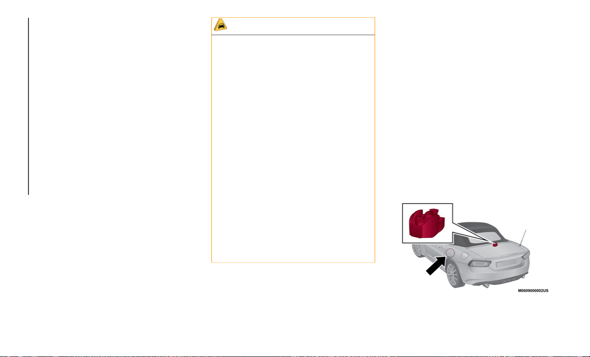
SERVICING AND MAINTENANCE
278
lukewarm or cold water. Also, be sure to
clean the wheels after driving on dusty or
salted roads to help prevent corrosion.
Convertible Top Maintenance
The convertible top is made of a special
high-grade material, but if it's not taken good
care of, hardening, staining, and loss of
luster will result. Maintain it under these
guidelines.
Washing
Do not wait until the convertible top gets
r
e
ally dirty before cleaning it. Dirt that's
there too long will cause deterioration.
Before washing, remove dust and coarse
particulate with a soft brush.
Gently clean the convertible top with a
synthetic neutral detergent, lots of water,
and a soft brush.
Rinse it thoroughly with clean water to
remove all the soap.
Wipe it as dry as you can before the water
dries on it.
Then allow it to dry completely before
lowering it.
NOTE:
Some leather treatment products can ruin
the convertible top's gloss. Be careful of
the one you choose.
Test on an inconspicuous, small corner of
the convertible top if you are not sure.
Do not get any car wax on the convertible
top.
If you do, remove it with a good leather
cleaner or mild detergent (about 5% solu-
tion).
Let the convertible top dry completely
before lowering after applying treatment or
dressing.
Drain Filter Cleaning
If leaves or other matter block the drain
fi
lter, water may enter the vehicle. Clean the
drain filter at least once a year.
Drain Filter
CAUTION!
Automatic and high-pressure car washes
are harmful to a convertible top. Avoid
them.
Do not spray water directly on the area
where the window glass and the convert-
ible top meet. This would probably cause
w
a
ter to enter the interior.
Do not spray water directly on the seam
area of the body and the convertible top
as it could result in water penetrating the
interior.
Do not wipe the convertible top using
alcohol, chlorine bleach, or organic
solvents such as thinner, benzene, or
gasoline. Otherwise, they may cause
discoloration or stains.
Too much treatment on the convertible
top can be as damaging as too little.
Follow the manufacturer's directions. Do
not over do it!
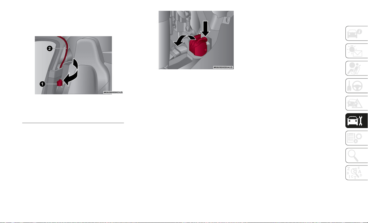
279
Proceed as follows:
1. Check the position of the drain filter with
y
our hand from behind the bow.
Drain Filter Location
2. R
emove the drain filter while pressing
t
he tab
Drain Filter Tab
3. Remove leaves and other matter accumu-
l
ated in the drain filter.
4. R
einstall the drain filter in the reverse
o
rder of the removal procedure.
NOTE:
Make sure that the drain filter is securely
at
tached to its designated position by
pushing it until the tab locks. Water may
enter the vehicle if the drain filter is not
secured to its designated position. For this
operation go to an authorized dealer.
Plastic Part Maintenance
When cleaning the plastic lenses of the
lights, do not use gasoline, paraffin, rectified
spirit, paint, thinner, highly acidic deter
-
gents, or strongly alkaline detergents.
Otherwise, these chemical agents can
di
scolor or damage the surfaces resulting in
a significant loss in functionality. If plastic
parts become inadvertently exposed to any of
these chemical agents, flush with water
immediately.
If plastic parts such as the bumpers become
in
advertently exposed to chemical agents or
fluids such as gasoline, oil, engine coolant,
or battery fluid, it could cause discoloration,
staining, or paint peeling. Wipe off any such
chemical agents or fluids using a soft cloth
immediately.
1 — Drain Filter
2 — Bow

SERVICING AND MAINTENANCE
280
(Continued)
INTERIORS
Seats And Fabric Parts
Vinyl
Remove dust and loose dirt from vinyl with a
wh
isk broom or vacuum cleaner. Clean vinyl
with a leather-and-vinyl cleaner.
Fabric
Remove dust and loose dirt from fabric with
a
whisk broom or vacuum cleaner. Clean it
with a mild soap solution good for upholstery
and carpets.
Remove fresh spots immediately with a
fa
bric spot cleaner.
To keep the fabric looking clean and fresh,
ta
ke care of it. Otherwise its color will be
affected, it can be stained easily, and its
fire-resistance may be reduced.
NOTE:
Use only recommended cleaners and proce-
dures. Others may affect appearance and
f
i
re-resistance.
Interior Panels
When the interior panels need to be cleaned,
u
s
e soft material such as a soft cloth soaked
in clean water and wrung out well and lightly
wipe off dirt from the surface.
If a panel requires further cleaning, wipe dirt
of
f using a soft cloth soaked in mild deter-
gent (about 5% solution) and wipe off any
r
e
maining detergent using a cloth soaked in
clean water and wrung out well.
CAUTION!
High water temperature and high water
pressure car washers are available
depending on the type of high pressure
car washer device. If the car washer
nozzle is put too close to the vehicle or
aimed at one area for an extended period
of time, it could deform plastic parts or
damage the paint.
Do not use wax containing compounds
(polish). Otherwise, it could result in
paint damage.
In addition, do not use an electrical or air
tool to apply wax. Otherwise, the fric-
tional heat generated could result in
d
e
formation of plastic parts or paint
damage.
WARNING!
Do not use volatile solvents for cleaning
purposes. Many are potentially flammable,
and if used in closed areas they may cause
respiratory harm.
Do not keep aerosol cans in the car: they
might explode. Aerosol cans must not be
exposed to a temperature exceeding 122°F
(50°C). When the vehicle is exposed to
sunlight the internal temperature can
greatly exceed this value.
CAUTION!
Direct contact of air fresheners, insect
repellents, suntan lotions, or hand sani-
tizers, to the plastic, painted, or deco-
rated surfaces of the interior may cause
p
e
rmanent damage. Wipe away immedi-
ately.
Damage caused by these type of prod-
ucts may not be covered by your New
Ve
hicle Limited Warranty.
Rubbing the interior side of the convert-
ible top vigorously with a stiff brush or
cl
oth may cause damage.
WARNING! (Continued)
281
NOTE:
Scratches or nicks on the panels and
metallic trim resulting from the use of a
hard brush or cloth may not be repairable.
Be particularly careful when cleaning high
gloss panels and metallic trim as they can
be easily scratched.
Lap / Shoulder Belt
Clean the webbing with a mild soap solution
re
commended for upholstery or carpets.
Follow instructions. Do not bleach or dye the
belts, this may weaken them.
After cleaning the belts, thoroughly dry the
be
lt webbing and make sure there is no
remaining moisture before retracting them.
Plastic And Coated Parts
Clean interior plastic parts with a damp cloth
(if possible made from microfiber), and a
solution of water and neutral, non-abrasive
detergent.
To clean oily or persistent stains, use
sp
ecific products free from solvents and
designed to maintain the original appearance
and color of the components.
Remove any dust using a microfiber cloth, if
ne
cessary moistened with water. The use of
paper tissues is not recommended as these
may leave residues.
Instrument Panel Precautions
Prevent caustic solutions such as perfume and
co
smetic oils from contacting the instrument
panel. They will damage and discolor the
instrument panel. If these solutions get on the
instrument panel, wipe them off immediately.
NOTE:
Never use alcohol, gasoline and derivatives
to
clean the instrument panel lens.
Instrument Panel Top
When cleaning, it is recommended that you
us
e a clean towel dampened in a mild deter-
gent to remove debris.
Window Interiors
If the windows become covered with an oily,
greasy, or waxy film, clean them with glass
cleaner. Follow the directions on the
container.
CAUTION!
Do not wipe leather parts using alcohol,
chlorine bleach, or organic solvents such
as thinner, benzene, or gasoline.
Otherwise, it may cause discoloration or
stains.
WARNING!
A frayed or torn belt could rip apart in a
collision and leave you with no protection.
Inspect the belt system periodically,
checking for cuts, frays, or loose parts.
Damaged parts must be replaced
immediately. Do not disassemble or modify
the system. Seat belt assemblies must be
replaced after a collision if they have been
damaged (i.e., bent retractor, torn
webbing, etc.).
CAUTION!
Do not use glazing agents. Glazing agents
contain ingredients which may cause
discoloration, wrinkling, cracks and
peeling.
CAUTION!
If the surface is rubbed harshly, it could
result in the surface being damaged
leaving white scratch marks.

SERVICING AND MAINTENANCE
282
(Continued)
NOTE:
Do not scrape or scratch the inside of the
wi
ndow glass. It could damage the thermal
filaments.
Leather Parts — If Equipped
Remove dust and sand first using a vacuum
cleaner or other means, then wipe dirt off
using a soft cloth with a leather cleaner or a
soft cloth soaked in mild soap.
Wipe off the remaining cleaner or soap using
a
cloth soaked in clean water and wrung out
well.
Remove moisture with a dry, soft cloth and
al
low the leather to further dry in a
well-ventilated, shaded area.
If the leather gets wet such as from rain, also
re
move moisture and dry it as soon as
possible.
NOTE:
Because genuine leather is a natural
material, its surface is not uniform and it
may have natural scars, scratches, and
wrinkles.
To maintain the quality for as long as
possible, periodical maintenance, about
twice a year, is recommended.
CAUTION!
When washing the inside of the window
glass, use a soft cloth dampened in
lukewarm water, gently wiping the thermal
filaments. Use of glass cleaning products
could damage the thermal filaments.
CAUTION!
Do not use Alcohol and Alcohol-based and/
or Ketone based cleaning products to
clean leather seats, as damage to the seat
may result.
CAUTION!
Sand and dust on the seat surface may
damage the overcoat of the genuine
leather surfaces and accelerate wear.
Greasy soiling on genuine leather may
cause molding and stains.
Rubbing hard with a stiff brush or cloth
may cause damage.
Do not wipe the leather using alcohol,
chlorine bleach, or organic solvents such
as thinner, benzene, or gasoline. Other
-
wise, it may cause discoloration or
st
ains.
If the seats get wet, promptly remove
moisture with a dry cloth. Remaining
moisture on the surface may cause dete
-
rioration such as hardening and
sh
rinkage.
Exposure to direct sunlight for long
periods may cause deterioration and
shrinkage. When parking the car under
direct sunlight for long periods, shade
the interior using sunshades.
Do not leave vinyl products on the seats
for long periods as they may affect the
leather quality and coloring. If the cabin
temperature becomes hot, the vinyl may
deteriorate and adhere to the genuine
leather.
CAUTION! (Continued)
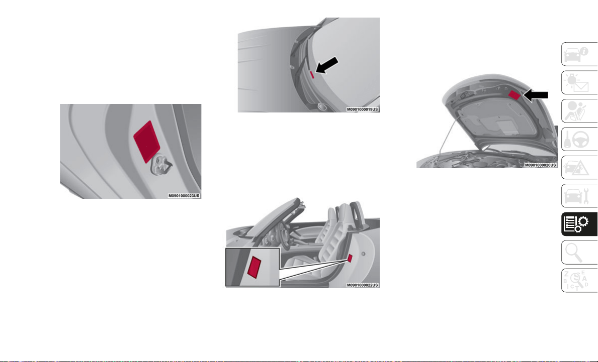
283
IDENTIFICATION DATA
Identification Numbers
Model Plate
The model plate is located on the left side of
doo
r pillar.
Model Plate Location
Vehicle Identification Number
The Vehicle Identification Number is located
b
el
ow the left side (driver side) of the wind-
shield.
Vehicle Identification Number
Motor Vehicle Safety Standard Label
(U.S.A. and Canada)
The motor vehicle safety standard label is
loc
ated on the left side of door pillar.
Motor Vehicle Safety Standard Label
Vehicle Emission Control Information Label
(U.S.A. and Canada)
The vehicle emission control information
l
ab
el is located under the hood.
Vehicle Emission Control Information Label

TECHNICAL SPECIFICATIONS
284
Tire Pressure Label
The tire pressure label is located on the left
si
de of door pillar.
Tire Pressure Label
Engine Number
The engine number label is located on the
e
n
gine.
RECOMMENDED TIRE
INFLATION PRESSURE
On the tire label you will find the recom-
mended tire inflation pressure in both psi
an
d kPa for the tires installed as original
equipment on the vehicle.
It is very important that the inflation pres-
sure of the tires on your vehicle is main-
tained at the recommended pressure.
You should check the tire pressure regularly
t
o
insure that the proper inflation pressure is
maintained.
NOTE:
Tire pressures listed on the vehicle
placard or tire information label indicate
the recommended cold tire inflation pres
-
sure, measured when the tires are cold,
af
ter the vehicle has been parked for at
least three hours. As you drive, the
temperature in the tire warms up,
increasing the tire pressure.
Always check the tire inflation pressures
on a regular basis according to the recom-
mended tire inflation pressure on the tire
l
a
bel and in conjunction with the informa-
tion in this Owner's Manual. Driving your
v
e
hicle with under-inflated tires is
dangerous. Under-inflation is the most
common cause of failures in any kind of
tire and may result in severe cracking,
tread separation or “blowout”, with unex
-
pected loss of vehicle control and
i
n
creased risk of injury. Under-inflation
increases sidewall flexing and rolling resis
-
tance, resulting in heat buildup and
i
n
ternal damage to the tire. It results in
unnecessary tire stress, irregular wear,
loss of control and accidents. A tire can
lose up to half of its air pressure and not
appear to be flat. It is impossible to deter
-
mine whether or not tires are properly
i
n
flated just by looking at them.
Checking Tire Pressure
Proceed as follows:
1. When you check the air pressure, make
s
ure the tires are cold - meaning they are
not hot from driving even a mile.
2. Remove the cap from the valve on one
t
ire.
3. Firmly press a tire gauge onto the valve.
4
. Add air to achieve recommended air
p
ressure.
5. If you overfill the tire, release air by
p
ushing on the metal stem in the center
of the valve. Then recheck the pressure
with your tire gauge.
6. Replace the valve cap.

285
7. Visually inspect the tires to make sure
there are no nails or other objects
embedded that could poke a hole in the
tire and cause an air leak.
8. Check the sidewalls to make sure there
a
re no gouges, cuts, bulges, cracks or
other irregularities.
Glossary Of Terms
Tire Placard
A label indicating the OE (Original Equip-
ment) tire sizes, recommended inflation
pr
essure, and the maximum weight the
vehicle can carry.
Tire Identification Number (TIN)
A number on the sidewall of each tire
pr
oviding information about the tire brand
and manufacturing plant, tire size, and date
of manufacture.
Inflation Pressure
A measure of the amount of air in a tire.
kPa
Kilopascal, the metric unit for air pressure.
psi
Pounds per square inch, the English unit for
ai
r pressure.
B-pillar
The structural member at the side of the
v
e
hicle behind the front door.
Original Equipment (OE)
Describes components originally equipped
o
n
the vehicle.
Vehicle Load Limit
The maximum value of the combination
we
ight of occupants and cargo.
Bead Area of the Tire
Area of the tire next to the rim.
Sidewall Area of the Tire
Area between the bead area and the tread.
Tread Area of the Tire
Area on the perimeter of the tire that
contacts the road when it's mounted on the
vehicle.
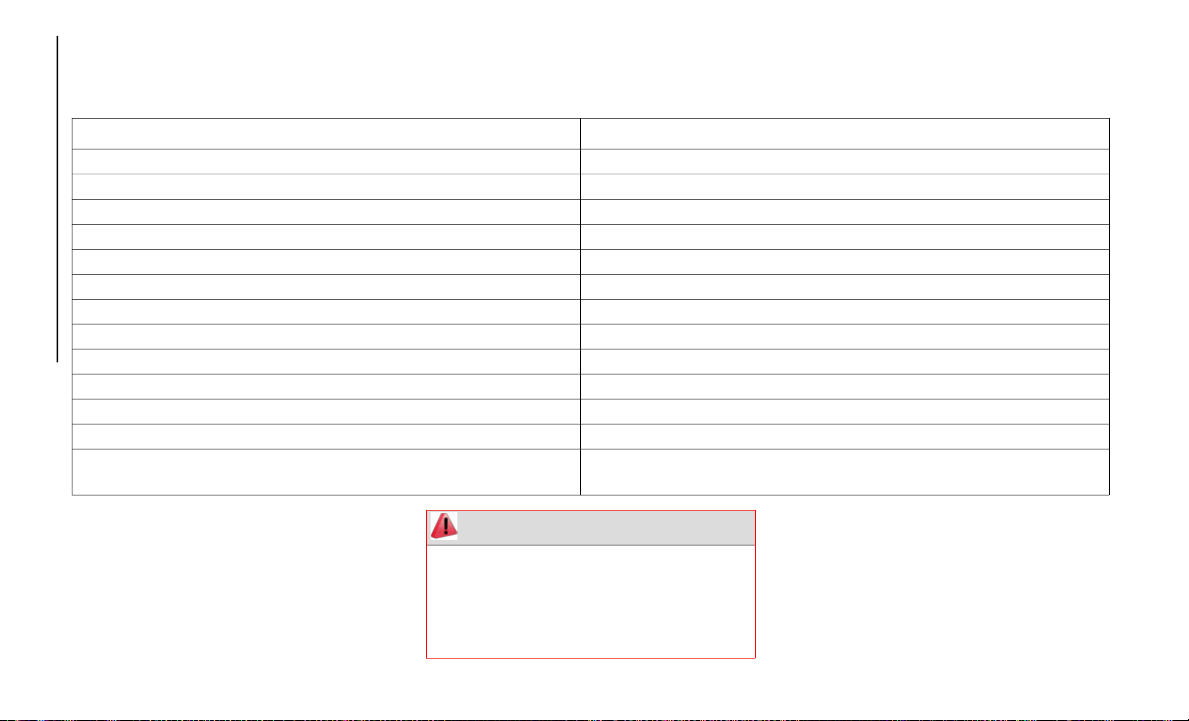
TECHNICAL SPECIFICATIONS
286
ENGINE
Engine
NOTE:
When cleaning the iridium plugs, do not use
a
wire brush. The fine particulate coating on
the iridium alloy and platinum tips could be
damaged.
1.4 Turbo Multi Air
Cycle Four
Number and position of cylinders 4 inline
Piston bore and stroke (mm) 72.0 x 80.4
Total displacement (cm³) 1,368
Compression ratio 9.8:1
Maximum power (kW) 119 (Non-Abarth), 122 (Abarth)
Maximum power (HP) 160 (Non-Abarth), 164 (Abarth)
Corresponding engine speed (RPM) 5,500
Maximum torque (Nm) 250
Maximum torque (lb.-ft.) 184
Corresponding engine speed (RPM) 2,500
Spark plugs We recommend you use Mopar Spark Plugs.
Fuel 91 Octane Recommended (87 Octane Acceptable) (R+M)/2 Method
M
a
ximum 15% Ethanol Content
WARNING!
Modifications or repairs to the fuel supply
system that are not carried out correctly or
do not take the system’s technical
specifications into account, can cause
malfunctions leading to the risk of fire.

287
TRANSMISSION
BRAKES
NOTE:
Water, ice, and salt spread on the roads ma y deposit on the brake disks reducing brakin g
efficiency the first time the brakes ar e applied.
SUSPENSIONS
STEERING
Engine Traction Type Description
1.4 Turbo Multi Air RWD Manual/Automatic
6-speed manual
1
/ 6-speed
Automatic Transmission
2
1. If equipped with manual transmission
2. If equipped with automatic transmission
Engine Front brakes Rear brakes Parking brake
1.4 Turbo Multi Air Ventilated (floating type 11 inch
(279.4 mm) diameter)
Solid (floating type 11 inch
(279.4 mm) in diameter)
Mechanical (lever type)
Engine Front Rear
1.4 Turbo Multi Air Double wishbone with stabilizer bars Multilink with stabilizer bars
Engine Turning circle curb to curb, ft (m) Type
1.4 Turbo Multi Air 30.8 (9.4) Double pinion electric power assist system
(DP - EPAS) - rack and pinion
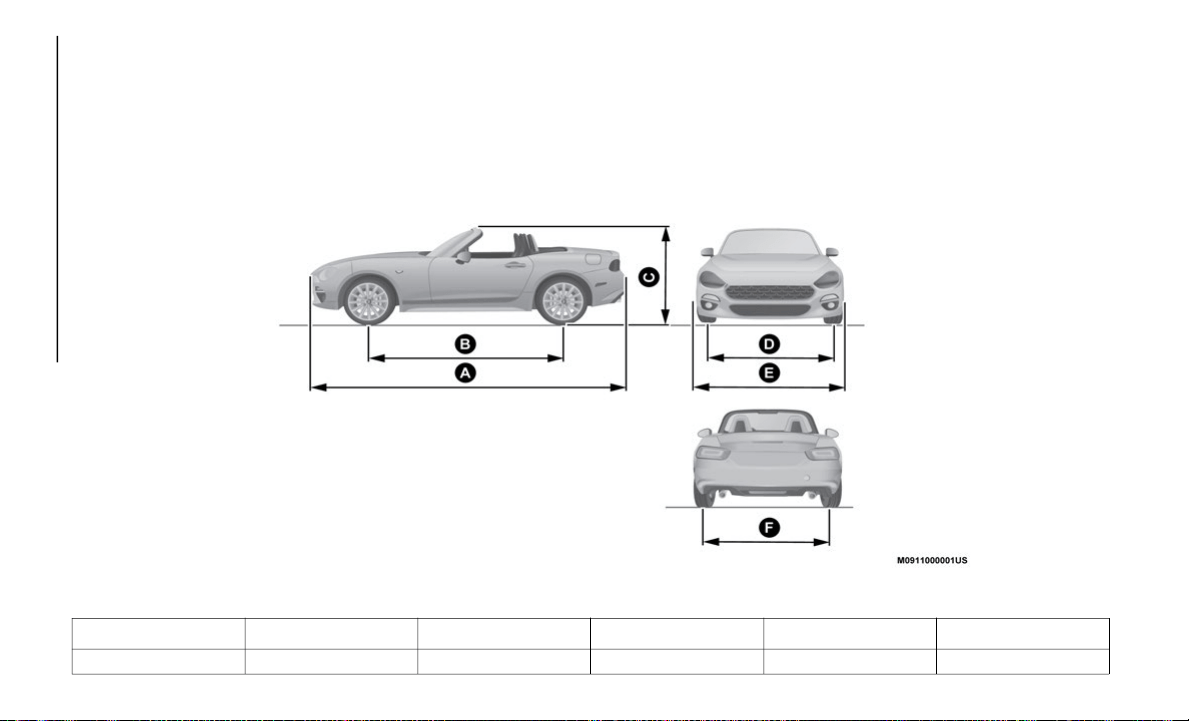
TECHNICAL SPECIFICATIONS
288
DIMENSIONS
Dimensions
Dimensions are expressed in inches and refer to the vehicle equipped with its standard-supplied tires. Height is measured with vehicle
unloaded.
Trunk Volume:
4.9 cu. ft. (140 Liters)
Vehicle Dimension Chart
A B C D E F
159.6 (4,054 mm) 90.9 (2,309 mm) 48.5 (1,232 mm) 58.9 (1,496 mm) 68.5 (1,740 mm) 59.1 (1,503 mm)

289
Weights
Curb Weight: 2,477 lbs (1,124 kg) (if equipped with manual transmission) / 2,516 lbs (1,141 kg) (if equipped with automatic transmission).
FLUID CAPACITIES
FLUIDS AND LUBRICANTS
Fluids And Lubricants
Your vehicle is equipped with an engine oil
that has been thoroughly developed and
tested in order to meet the requirements of
the Scheduled Servicing Plan.
Constant use of the prescribed lubricants
gu
arantees the fuel consumption and emis-
sion specifications. Lubricant quality is
c
r
ucial for engine operation and duration.
Item Capacities
Fuel tank 11.9 (gallons) / 45 (liters)
Engine oil (without oil filter replacement) 3.3 (quarts) / 3.2 (liters)
Engine oil (with oil filter replacement) 4.0 (quarts) / 3.8 (liters)
Coolant (with manual transmission) 7.6 (quarts) / 7.2 (liters)
Coolant (with automatic transmission) 7.5 (quarts) / 7.1 (liters)
Manual transmission oil 2.2 (quarts) / 2.1 (liters)
Automatic transmission fluid 7.8 (quarts) / 7.5 (liters)
Rear differential oil 0.63 (quarts) / 0.6 (liters)
Limited slip differential oil 0.63 (quarts) / 0.6 (liters)
Brake fluid (& clutch fluid) 0.57 (quarts) / 0.55 (liters)

TECHNICAL SPECIFICATIONS
290
If lubricants compliant with the required specifications are not available, products that comply with the minimum required characteristics
can be used for topping up; in this case optimal performance of the engine is not guaranteed.
Lubricant Specification Replacement interval
Engine oil We recommend you use API Certified SAE
5W-40 Full Synthetic Engine Oil, meeting
the requirements of FCA Material Standard
MS-12991. Refer to your engine oil filler cap
for correct SAE grade.
According to Scheduled Servicing Plan
Coolant Mopar Long Life Coolant Concentrate for
FI
AT Spider
According to Scheduled Servicing Plan
Manual transmission oil Mopar Manual Transmission Long Life Gear
Oi
l for FIAT Spider
Automatic transmission fluid Mopar Automatic Transmission Long Life
Fl
uid for FIAT Spider
Rear differential oil Mopar Long Life Hypoid Gear Oil for FIAT
Sp
ider
Limited slip differential oil Mopar Long Life Limited Slip Additive for
FI
AT Spider
Brake/clutch fluid We recommend you use Mopar DOT 3. If
DO
T 3 brake fluid is not available, then DOT
4 is acceptable.

291
(Continued)
PERFORMANCE
Performance
Top speed after the initial period of usage of
the vehicle.
CAUTION!
Mixing of engine coolant (antifreeze)
other than specified Organic Additive
Technology (OAT) engine coolant (anti
-
freeze), may result in engine damage
an
d may decrease corrosion protection.
Organic Additive Technology (OAT)
engine coolant is different and should
not be mixed with Hybrid Organic Addi
-
tive Technology (HOAT) engine coolant
(a
ntifreeze) or any “globally compatible”
coolant (antifreeze). If a non-OAT engine
coolant (antifreeze) is introduced into
the cooling system in an emergency, the
cooling system will need to be drained,
flushed, and refilled with fresh OAT
coolant (conforming to MS.90032), by
an authorized dealer as soon as possible.
Do not use water alone or alcohol-based
engine coolant (antifreeze) products. Do
not use additional rust inhibitors or anti
-
rust products, as they may not be
co
mpatible with the radiator engine
coolant and may plug the radiator.
This vehicle has not been designed for
use with propylene glycol-based engine
coolant (antifreeze). Use of propylene
glycol-based engine coolant (antifreeze)
is not recommended.
CAUTION! (Continued)
Version MPH (km/h)
1.4 Turbo Multi Air
160HP (Non-Abarth)
N/A
1.4 Turbo Multi Air
16
4HP (Abarth)
130 (209.2)

292
CUSTOMER ASSISTANCE
SUGGESTIONS FOR
OBTAINING SERVICE FOR
YOUR VEHICLE
Prepare For The Appointment
If you are having warranty work done, be sure
to bring the right papers with you. All work to
be performed may not be covered by the
warranty. Discuss additional charges with
the service manager. Keep a maintenance
log of your vehicle's service history, as this
can often provide a clue to the current
problem.
Prepare A List
Make a written list of your vehicle's problems
or the specific work you want done. If you've
had an accident or work done that is not on
your maintenance log, let the service advisor
know.
Be Reasonable With Requests
If you list a number of items and you must
have your vehicle by the end of the day,
discuss the situation with the service advisor
and list the items in order of priority. At many
authorized dealers, you may obtain a rental
vehicle at a minimal daily charge. If you need
a rental, it is advisable to make these
arrangements when you call for an appoint
-
ment.
IF YOU NEED ASSISTANCE
The manufacturer and its authorized dealers
are vitally interested in your satisfaction. We
want you to be happy with our products and
services.
Warranty service must be done by an autho-
rized dealer. We strongly recommend that
yo
u take the vehicle to an authorized dealer.
They know your vehicle the best, and are
most concerned that you get prompt and
high quality service. The manufacturer's
authorized dealers have the facilities,
factory-trained technicians, special tools,
and the latest information to ensure the
vehicle is fixed correctly and in a timely
manner.
This is why you should always talk to an
au
thorized dealer service manager first. Most
matters can be resolved with this process.
If for some reason you are still not satis-
fied, talk to the general manager or owner
of
the authorized dealer. They want to
know if you need assistance.
If an authorized dealer is unable to resolve
the concern, you may contact the manu-
facturer's customer center.
Any communication to the manufacturer's
c
u
stomer center should include the following
information:
Owner's name and address
Owner's telephone number (home, mobile,
and office)
Authorized dealer name
Vehicle Identification Number (VIN)
Vehicle delivery date and mileage
FIAT Customer Center
P.O. Box 21–8004 Auburn Hills, MI
48321–8004
Phone:
1-888-242-6342
FIAT Canada Customer Center
P.O. Box 1621
Windsor, Ontario N9A 4H6
Phone: (800) 465-2001 English / (800)
38
7-9983 French

293
In Mexico Contact
Av. Prolongacion Paseo de la Reforma, 1240
Sante Fe C.P. 05109
Mexico, D. F.
In Mexico City: 5081-7568
Outside Mexico City: 1
-
800-505-1300
Puerto Rico And U.S. Virgin Islands
Customer Service Chrysler International
Services LLC
P.O. Box 191857
San Juan 00919-1857
Tel.: (888) 242-6342
Fax: (787) 782-3345
Customer Assistance For The Hearing Or
Speech Impaired (TDD/TTY)
To assist customers who have hearing diffi-
culties, the manufacturer has installed
sp
ecial Telecommunication Devices for the
Deaf (TDD) equipment at its customer
center. Any hearing or speech impaired
customer, who has access to a TDD or a
conventional teletypewriter (TTY) in the
United States, can communicate with the
manufacturer by dialing 1-800-380-CHRY.
Canadian residents with hearing difficulties
th
at require assistance can use the special
needs relay service offered by Bell Canada.
For TTY teletypewriter users, dial 711 and
for Voice callers, dial 1-800-855-0511 to
connect with a Bell Relay Service operator.
Service Contract
You may have purchased a service contract
for a vehicle to help protect you from the
high cost of unexpected repairs after the
manufacturer's New Vehicle Limited
Warranty expires. The manufacturer stands
behind only the manufacturer's service
contracts. If you purchased a manufacturer's
service contract, you will receive Plan Provi
-
sions and an Owner Identification Card in the
ma
il within three weeks of the vehicle
delivery date. If you have any questions
about the service contract, call the manufac
-
turer's Service Contract National Customer
Ho
tline at 1-800-521-9922 (Canadian resi-
dents, call (800) 465-2001 English / (800)
3
8
7-9983 French).
The manufacturer will not stand behind any
se
rvice contract that is not the manufac-
turer's service contract. It is not responsible
f
o
r any service contract other than the manu-
facturer's service contract. If you purchased
a
service contract that is not a manufac-
turer's service contract, and you require
s
e
rvice after the manufacturer's New Vehicle
Limited Warranty expires, please refer to the
contract documents, and contact the person
listed in those documents.
We appreciate that you have made a major
investment when you purchased the vehicle.
An authorized dealer has also made a major
investment in facilities, tools, and training to
assure that you are absolutely delighted with
the ownership experience. You will be
pleased with their sincere efforts to resolve
any warranty issues or related concerns.

CUSTOMER ASSISTANCE
294
WARRANTY INFORMATION
See the Warranty Information available
online, for the terms and provisions of FCA
US LLC and FCA Canada Inc. warranties
applicable to this vehicle and market.
REPORTING SAFETY
DEFECTS
In The 50 United States And Washington,
D.C.
If you believe that your vehicle has a
defect that could cause a crash or
cause injury or death, you should
immediately inform the National
Highway Traffic Safety Administration
(NHTSA) in addition to notifying FCA
US LLC.
If NHTSA receives similar complaints,
it
may open an investigation, and if it
finds that a safety defect exists in a
group of vehicles, it may order a recall
and remedy campaign. However,
NHTSA cannot become involved in
individual problems between you, an
authorized dealer or FCA US LLC.
To contact NHTSA, you may call the
Ve
hicle Safety Hotline toll free at
1-888-327-4236 (TTY:
1-800-424-9153); or go to http://
www.safercar.gov; or write to: Admin-
istrator, NHTSA, 1200 New Jersey
Av
enue, SE., West Building, Wash-
ington, D.C. 20590. You can also
ob
tain other information about motor
vehicle safety from http://
www.safercar.gov.
In Canada
If you believe that your vehicle has a
safety defect, you should contact the
Customer Service Department imme-
diately. Canadian customers who wish
to
report a safety defect to the Cana-
dian government should contact
Tr
ansport Canada, Motor Vehicle
Defect Investigations and Recalls at
1-800-333-0510 or go to http://
www.tc.gc.ca/roadsafety/.
WARNING!
Engine exhaust (internal combustion
engines only), some of its constituents,
and certain vehicle components contain,
or emit, chemicals known to the State of
California to cause cancer and birth
defects, or other reproductive harm. In
addition, certain fluids contained in
vehicles and certain products of
component wear contain, or emit,
chemicals known to the State of California
to cause cancer and birth defects, or other
reproductive harm.

295
PUBLICATION ORDER
FORMS
To order the following manuals, you may use
either the website or the phone numbers
listed below. Visa, Mastercard, American
Express, and Discover orders are accepted.
Service Manuals
These comprehensive Service Manuals
pr
ovide the information that students and
professional technicians need in diagnosing/
troubleshooting, problem solving, main
-
taining, servicing, and repairing FCA US LLC
ve
hicles. A complete working knowledge of
the vehicle, system, and/or components is
written in straightforward language with
illustrations, diagrams, and charts.
Diagnostic Procedure Manuals
Diagnostic Procedure Manuals are filled with
di
agrams, charts and detailed illustrations.
These practical manuals make it easy for
students and technicians to find and fix
problems on computer-controlled vehicle
systems and features. They show exactly how
to find and correct problems the first time,
using step-by-step troubleshooting and driv
-
ability procedures, proven diagnostic tests
an
d a complete list of all tools and equip-
ment.
Owner's Manuals
These Owner's Manuals have been prepared
w
i
th the assistance of service and engi-
neering specialists to acquaint you with
s
p
ecific FCA US LLC vehicles. Included are
starting, operating, emergency and mainte
-
nance procedures as well as specifications,
ca
pabilities and safety tips.
Call toll free at:
1-800-890-4038 (US)
1-800-387-1143 (Canada)
Or
Visit us on the Worldwide Web at:
www.techauthority.com

296
INDEX
INDEX
A
About Your Brakes ..
........................... 161
Active Adaptive Shift (AAS) ..
..............168
Adaptive Front Lighting System (AFS)..
..42
Additives, Fuel ..
................................ 186
Air Bag ..................................... 1
41, 146
Advance Front Air Bag ..
.................. 141
Air Bag Warning Light..
...................158
Enhanced Accident Response.. 1
58, 238
Event Data Recorder (EDR) ..
... 157, 238
Maintaining Your Air Bag System ..
... 156
Maintenance..
................................ 156
Air Bag Light..
...................................158
Air Conditioning..
.................................50
Air Pressure
Tires .
............................................2
62
Alarm
Security Alarm .
.
...............................23
Anti-Lock Brake System (ABS) ..
..........117
Automatic Climate Controls ..
................53
Automatic Dimming Mirror..
..................36
Automatic Transmission ..
...................164
Auxiliary (Power Outlet) ..
......................75
Auxiliary Driving Systems..
.................. 120
B
Back-Up Camera ..
.............................178
Battery .
............................................ 2
51
Charging ....................................... 2
51
Keyless Key Fob Replacement..
......... 14
Blind Spot Monitoring..
...................... 120
Bodywork.......................................... 2
73
Brake System..
.................................. 161
Brakes.............................................. 2
87
Bulb Replacement..
........................... 197
C
Camera, Rear ..
.................................. 178
Carbon Monoxide Warning ..
................ 186
Care And Maintenance..
..................... 273
Certification Label ..
........................... 188
Changing A Flat Tire ..
.................215, 255
Chart, Tire Sizing ..
............................ 256
Check Engine Light (Malfunction
Indicator Light) .
.
............................... 115
Child Restraint ..
................................ 137
Clean Air Gasoline ..
........................... 185
Cleaning
Wheels.
......................................... 2
68
Climate Control ..
................................. 44
Automatic ....................................... 5
3
Manual ........................................... 4
8
Compact Spare Tire ..
......................... 267
Contract, Service ..
............................. 293
Convertible Top.
.
..................................59
Lowering..........................................5
9
Precautions..
....................................62
Raising ............................................6
1
Cooling System ..
..................................50
Coolant Level ..
...............................248
Corrosion Protection ..
.........................273
Cruise Control (Speed Control)..
...........171
Cupholders ..
........................................76
Customer Assistance ..
........................292
D
Daytime Running Lights..
......................39
Diagnostic System, Onboard..
..............115
Dimensions ..
.....................................288
Disable Vehicle Towing ...............235, 237
Door Opener, Garage ..
..........................67
Doors ..................................................2
6
Driving
Tips .
.............................................1
90
Dynamic Stability Control System
(DSC).
...............................................1
18
E
Electric Brake Control System
Traction Control System ..
................118
Electric Power Steering..
.......................77

297
Engine Oil (Level Check) .................... 248
Environmental Protection Systems..
.......77
Essential Information ..
........................... 3
F
Flashers
Hazard Warning ..
........................... 196
Flash-To-Pass..
....................................39
Flat Tire Changing ..
................... 255, 266
Flat Tire Stowage..
..................... 255, 266
Flooded Engine Starting ..
...................234
Fluid Capacities..
...............................289
Fluid Level Checks
Automatic Transmission.
.
................250
Brake ............................................ 2
49
Clutch........................................... 2
49
Cooling System ..
............................ 248
Fluids And Lubricants ..
...................... 289
Fob, Key .............................................1
2
Fog Lights........................................... 4
1
Fuel
Additives .
...................................... 1
86
Clean Air ....................................... 1
85
Consumption ..
.................................90
Economy Monitor ..
...........................90
Ethanol .........................................1
85
Filler Cap (Gas Cap) ..
.....................187
Materials Added ..
........................... 186
Methanol.......................................1
85
Fuses
Engine Compartment..
.................... 211
Interior ..................................209,
214
Underhood ..
.................................. 210
G
Garage Door Opener (HomeLink) ..
......... 67
Gasoline, Clean Air ..
.......................... 185
Gasoline, Reformulated..
.................... 185
Gear Ranges ..
................................... 166
Glass Cleaning ..
................................ 281
GVWR .............................................. 1
88
H
Hazard Warning Flashers..
.................. 196
Head Restraints ..
................................ 34
Headlight
Adjustment .
.
................................... 42
Headlights ..
........................................ 38
Automatic ....................................... 4
0
High Beam..
.................................... 39
Switch ............................................ 3
8
Time Delay..
.................................... 40
Heated Mirrors ..
.................................. 38
Heated Seats ..
.................................... 33
Heavy-Duty Use..
............................... 240
HomeLink (Garage Door Opener) ..
......... 67
Hood
Closing .
.......................................... 6
4
Opening .......................................... 6
3
Hood Release ..
....................................63
How To Use This Manual ..
......................3
I
Identification Data ..
...........................283
Ignition ...............................................1
9
Switch.............................................1
9
Instrument Cluster
Display .
...........................................7
9
Engine Oil Reset..
.......................87, 88
Interior..............................................2
80
Interior Appearance Care ..
..................280
Interior Lights..
............................ 73, 208
Internal Equipment ..............................72
Storage............................................7
2
J
Jack Location ..
..................................216
Jack Operation..
.................................255
Jacking And Tire Changing..
........215, 216
Jacking And Tire Changing
Instructions .
.
.....................................217
Jacking Instructions ..
.........................217
Jump Starting..
.......................... 232, 233
K
Key Fob
Programming Additional Key Fobs ..
....23
Key Fob Battery Service (Remote Keyless
Entry) .
................................................1
4

298
INDEX
Key Fob Programming (Remote Keyless
Entry) .................................................2
3
Keyless Enter-N-Go..
............................20
Passive Entry ..
.................................20
Keys................................................... 1
2
L
Lane Change Assist..
............................41
Lap/Shoulder Belts ..
..........................131
Leaving Home Light System..
................42
Life Of Tires ..
....................................264
Lights
Air Bag.
.........................................1
58
Battery Saver ..
.................................73
Bulb Replacement..
........................199
Daytime Running ..
...........................39
Fog .................................................4
1
Hazard Warning Flasher ..
................196
Headlights..
...................................199
High Beam ..
....................................39
Illuminated Entry ..
...........................73
Interior............................................7
3
Leaving Home Light System ..
............42
Rear Tail Lamps..
........................... 199
Turn Signals ..
.................................. 41
Loading Vehicle ..
...............................188
Tires .............................................2
59
Locks
Power Door .
.
....................................30
Lubrication, Body ..
............................ 252
M
Maintenance Monitor ..
......................... 87
Maintenance Procedures ..
.................. 252
Malfunction Indicator Light (Check
Engine) .
........................................... 1
16
Manual
Service .
........................................ 2
95
Manual Climate Controls ..
.................... 48
Heating........................................... 5
0
Manual Transmission ..
....................... 163
Methanol .......................................... 1
85
Mirrors ............................................... 3
5
Automatic Dimming ..
....................... 36
Electric Powered..
............................ 37
Exterior Folding ..
............................. 37
Heated............................................ 3
8
Outside ........................................... 3
5
Rearview ......................................... 3
6
Vanity ............................................. 7
3
O
Occupant Restraints ..
........................ 130
Oil Reset .......................................8
7, 88
Onboard Diagnostic System ..
.............. 115
Opener, Garage Door (Homelink)..
......... 67
Operating Precautions..
...................... 115
Operator Manual
Owner's Manual .
.
........................... 295
Outside Rearview Mirrors..
.................... 35
Overheating, Engine..
......................... 234
P
Paint Care ..
.......................................273
Park Assist ..
......................................175
Parking Brake ..
..................................162
Passive Entry ..
.....................................20
Performance ..
....................................291
Periodic Checks ..
...............................240
Personal Settings ..
.............................111
Personalization Features ..
...................111
Placard, Tire And Loading
Information .
.
.....................................259
Power
Brakes.
..........................................
161
Door Locks..
.....................................30
Outlet (Auxiliary Electrical Outlet) ..
....75
Outside Mirrors..
...............................37
Windows ..........................................5
7
Pregnant Women And Seat Belts ..
.......134
Preparation For Jacking ..
....................216
Pretensioners
Seat Belts.
.....................................1
36
R
Radar Sensors ..
.................................174
Radial Ply Tires..
................................263
Radio Transmitter and Mobile Phones ..
....4
Rear ParkSense System ..
....................175
Rearview Mirror..
..................................36
Recommended Tire Inflation Pressure ..2
84
Recreational Towing ..
.........................189

299
Reformulated Gasoline .......................185
Refueling Procedure..
.........................187
Refueling The Vehicle ..
...................... 184
Reminder, Seat Belt..
.........................136
Remote Keyless Entry
Programming Additional Key Fobs.
.
.... 23
Replacement Fuses..
..........................209
Replacement Tires ..
........................... 265
Reporting Safety Defects ..
.................. 294
Restraints, Child..
..............................137
Restraints, Head..
................................34
S
Safety Defects, Reporting ..
................. 294
Safety Information, Tire..
....................255
Schedule, Maintenance ..
....................239
Scheduled Servicing ..
........................240
Seat Belts .........................................1
31
Child Restraints ..
........................... 137
Energy Management Feature ..
.........137
Front Seat ..
........................... 131, 135
Lap/Shoulder Belt Operation..
..........135
Lap/Shoulder Belts ..
....................... 131
Operating Instructions ..
.................. 135
Pregnant Women..
..........................134
Pretensioners..
...............................136
Rear Seat ......................................1
31
Reminder ......................................1
36
Seat Belt Pretensioner ..
.................. 136
Seat Belt Reminder ..
...................... 136
Seats ................................................. 3
2
Adjustment ..
................................... 32
Heated............................................ 3
3
Height Adjustment ..
......................... 32
Reclining ........................................ 3
2
Security Alarm ..
.................................. 23
Service Assistance..
........................... 292
Service Contract ..
.............................. 293
Service Manuals ..
.............................. 295
Shift Lever Override..
..................168, 169
Shifting
Automatic Transmission .
.
............... 166
Shoulder Belts ..
................................ 131
Snow Tires..
...................................... 266
Spare Tires ..
......................266, 267, 268
Sport Mode..
..................................... 171
Starting .....................................1
60, 234
Button ............................................ 1
9
Engine Fails To Start..
.................... 234
Starting And Operating ..
.................... 234
Starting Procedures ..
......................... 234
Steering ........................................... 2
87
Tilt Column ..
................................... 35
Wheel, Tilt ..
.................................... 35
Storage
Console.
.......................................... 7
2
Storage, Vehicle ..
.............................. 272
Storing Your Vehicle ..
........................ 272
Sun Visor............................................ 7
3
Supplemental Restraint System –
Air Bag ..................................... 1
41, 146
Suspensions ..
....................................287
Symbols ................................................3
T
T
ire And Loading Information Placard ..2
59
Tire Markings.....................................255
Tire Repair Kit ..
.................................221
Tire Safety Information ..
.....................255
Tire Service Kit ..
................................221
Tires ................................. 2
61, 266, 271
Aging (Life Of Tires)..
......................264
Air Pressure ..
.................................261
Chains...........................................2
69
Changing ...............................2
17, 255
Compact Spare..
.............................267
Flat Changing..
.......................215, 217
General Information ..
..............261, 266
High Speed..
..................................263
Inflation Pressure ..
.........................262
Jacking..........................................2
55
Life Of Tires..
.................................264
Load Capacity ..
..............................259
Pressure Monitoring System
(TPMS) .
.....................................1
26
Quality Grading ..
............................271
Radial ...........................................2
63
Replacement..
................................265

300
INDEX
Rotation ........................................ 270
Safety ................................... 2
55, 261
Sizes............................................. 2
56
Snow Tires..
...................................266
Spare Tires ..
.......................... 266, 268
Spinning ....................................... 2
64
Tread Wear Indicators..
...................264
Towing
Disabled Vehicle .
.
.................. 235, 237
Towing Eyes ..
....................................235
Traction Control..
...............................118
Trailer Towing ..
................................. 189
Transmission..
...................................287
Transmitter, Garage Door Opener
(Homelink).
.
........................................ 67
Tread Wear Indicators ..
...................... 264
Trip Computer ..
................................... 81
Trunk Lid (Deck Lid) ..
..........................64
Turn Signals..
......................................41
U
Uconnect Settings
Customer Programmable Features..
.... 20
Passive Entry Programming..
............. 20
Uniform Tire Quality Grades ..
............. 271
Universal Transmitter..
......................... 67
V
Vehicle Loading..
........................188, 259
Vehicle Modifications/Alterations ..
.......... 3
Vent Operation ..
.................................. 45
W
Warranty Information ..
....................... 294
Washers, Windshield..
............. 42, 44, 250
Wheel And Wheel Tire Care ..
.............. 268
Wheel And Wheel Tire Trim ..
.............. 268
Wheels And Tires............................... 255
Wind Blocker .
.
.................................... 77
Windows .............................................5
7
Power ..............................................5
7
Windshield Washers ..
...........................42
Windshield Wiper Blades ..
..................253
Windshield Wipers ..
.....................42, 253
Wipers Blade Replacement ..
...............253
Wipers, Rain Sensitive..
........................42
Wrecker Towing ..
.......................235, 237

INSTALLATION OF RADIO TRANSMITTING
EQUIPMENT
Special design considerations are incorporated into this
vehicle’s electronic system to provide immunity to radio
frequency signals. Mobile two-way radios and telephone
equipment must be installed properly by trained person-
nel. The following must be observed during installation.
The positive power connection should be made
directly to the baery and fused as close to the baery as
possible. The negative power connection should be made
to body sheet metal adjacent to the negative baery
connection. This connection should not be fused.
Antennas for two-way radios should be mounted on
the roof or the rear area of the vehicle. Care should be
used in mounting antennas with magnet bases. Magnets
may aect the accuracy or operation of the compass on
vehicles so equipped.
The antenna cable should be as short as practical and
routed away from the vehicle wiring when possible. Use
only fully shielded coaxial cable.
Carefully match the antenna and cable to the radio to
ensure a low Standing Wave Ratio (SWR).
Mobile radio equipment with output power greater than
normal may require special precautions.
All installations should be checked for possible
interference between the communications equipment
and the vehicle’s electronic systems.
Operating, servicing and maintaining a
passenger vehicle or o-highway motor
vehicle can expose you to chemicals inclu-
ding engine exhaust, carbon monoxide,
phthalates, and lead, which are known to
the State of California to cause cancer and
birth defects or other reproductive harm.
To minimize exposure, avoid breathing
exhaust, do not idle the engine except as ne-
cessary, service your vehicle in a well-ven-
tilated area and wear gloves or wash
your hands frequently when servicing
your vehicle. For more information go to
www.P65Warnings.ca.gov/passenger-vehicle.
WARNING:
VEHICLES SOLD IN CANADA
With respect to any vehicles sold in Canada, the name
FCA US LLC shall be deemed to be deleted and the
name FCA Canada Inc. used in substitution therefore.
DRIVING AND ALCOHOL
Drunken driving is one of the most frequent causes of
accidents.
Your driving ability can be seriously impaired with
blood alcohol levels far below the legal minimum. If
you are drinking, do not drive. Ride with a designated
non-drinking driver, call a cab, a friend, or use public
transportation.
This manual illustrates and describes the operation
of features and equipment that are either standard or
optional on this vehicle. This manual may also include
a description of features and equipment that are no
longer available or were not ordered on this vehicle.
Please disregard any features and equipment described
in this manual that are not on this vehicle.
FCA US LLC reserves the right to make changes in
design and specications, and/or make additions to
or improvements to its products without imposing
any obligation upon itself to install them on products
previously manufactured.
Driving after drinking can lead to an accident.
Your perceptions are less sharp, your reexes are
slower, and your judgment is impaired when you
have been drinking. Never drink and then drive.
WARNING!
Copyright © 2019 FCA US LLC

2020
FIAT
®
124 SPIDER
FIAT
®
124 SPIDER
2020
OWNER'S MANUAL
Printed in U.S.A.
20_BA_OM_EN_USC
124 Spider
First Edition
Owner’s Manual
©2019 FCA US LLC. All Rights Reserved.
FIAT is a registered trademark of FCA Group Marketing S.p.A., used under license by FCA US LLC. App
Store is a registered trademark of Apple Inc. Google Play Store is a registered trademark of Google.