The data contained in this publication is intended merely as a guide. FIAT reserves the right to modify the models and
versions described in this booklet at any time for technical and commercial reasons.
If you have any further questions please consult your FIAT dealer.
Printed in recycled paper without chlorine.
OWNER HANDBOOK
FIATBRAVO
ENGLISH
BRAVO LUM GB:BRAVO UM GB 24-05-2012 14:30 Pagina 1
We really know your car because we invented, designed and built it: we really know every single detail.
At Fiat Service authorised workshops you can find technicians directly trained by us,
offering quality and professionalism for all service operations.
Fiat workshops are always close to you for the regular servicing operations, season checks
and practical recommendations by our experts.
With Fiat Genuine Parts you keep the reliability, comfort and performance features
of your new car unchanged in time: that's why you bought it for.
Always ask for Genuine Parts for the components used on our cars; we recommend them because
they come from our steady commitment in research and development of highly innovative technologies.
For all these reasons: rely on Genuine Parts, because they are the only ones designed
by Fiat for your car.
SAFETY:
BRAKING SYSTEM
ENVIRONMENT: PARTICULATE FILTERS,
CLIMATE CONTROL MAINTENANCE
COMFORT: SUSPENSION
AND WINDSCREEN WIPERS
PERFORMANCE: SPARK PLUGS,
INJECTORS AND BATTERIES
LINEACCESSORI
ROOF RACK BARS, WHEEL RIMS
WHY CHOOSING
GENUINE PARTS
BRAVO LUM GB:BRAVO UM GB 24-05-2012 14:30 Pagina 2
CHOOSING GENUINE PARTS
IS THE MOST NATURAL CHOICE
PERFORMANCE
GENUINE PARTS
COMFORT
GENUINE PARTS
SAFETY
GENUINE PARTS
AMBIENT
GENUINE PARTS
VALUES
GENUINE PARTS
ACCESSORIES
GENUINE PARTS
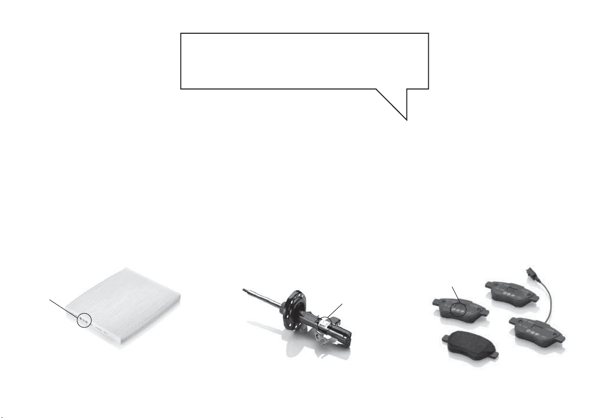
HOW TO RECOGNISE
GENUINE PARTS
Pollen filter
Genuine
Parts
Shock absorber
Genuine
Parts
Brake pads
Genuine
Parts
To recognise a Genuine Part, check that the component bears our brands, always clearly visible on Genuine Parts,
from the braking system to windscreen wipers, from shock absorbers to pollen filter.
All Genuine Parts undergo strict controls, both during design and manufacturing stages,
by specialists using vanguard materials, to test the component reliability.
This to guarantee performance and safety for you and your passengers on board, for a long time.
Always ask for and make sure a Genuine Part has been used.
Dear Customer,
We would like to congratulate and thank you for choosing a Fiat Bravo.
We have written this handbook to help you get to know all the features of your car and use it in the best possible way.
You are recommended to read it right through before taking to the road for the first time.
It contains important information, advice and instructions for the use of the car which will help you get the very best out
of your Fiat. The handbook also provides a description of special features and tips as well as essential information for
correct care, maintenance, safe car driving and use and preservation of your Fiat over time.
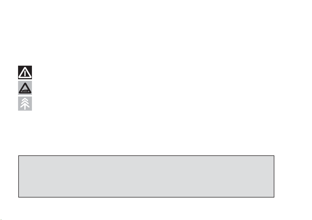
Carefully read the warnings and indications marked with the following symbols:
personal safety;
car safety;
environmental protection.
The enclosed Warranty Booklet lists the services that Fiat offers to its Customers:
❒ the Warranty Certificate with terms and conditions for maintaining its validity;
❒ the range of additional services available to Fiat Customers.
We are sure that these will help you familiarise with your new car and appreciate it and the care provided by the people
at Fiat.
Enjoy reading. Happy motoring!
This Owner Handbook describes all the versions of the Fiat Bravo. As a
consequence, you should only consider the information which is related to the trim
level, engine and version that you have purchased. All data contained in this
publication are purely indicative. Fiat Group Automobiles can modify the
specifications of the vehicle model described in this publication at any time, for
technical or commercial reasons. For further information, contact a Fiat Dealership.
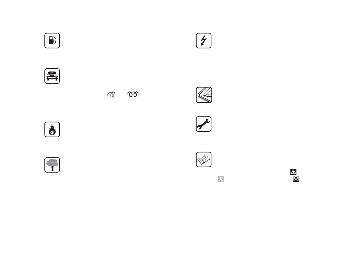
ESSENTIAL INFORMATION!
REFUELLING
Only use diesel fuel compliant with European
specification EN590. The use of other products
or mixtures may damage the engine beyond
repair and consequently invalidate the warranty.
STARTING THE ENGINE
Make sure that the handbrake is engaged; place
the gear lever in neutral. Fully depress the clutch
pedal, without pressing the accelerator, then
turn the ignition key to the MAR-ON position
and wait for the
and warning lights
to switch off; turn the ignition key to AVV and
release it as soon as the engine starts.
PARKING ON FLAMMABLE MATERIAL
The catalytic converter develops high
temperatures during operation. Do not park the
car on grass, dry leaves, pine needles or other
flammable material: fire hazard.
RESPECTING THE ENVIRONMENT
The car is fitted with a system that allows
continuous diagnosis of the components related
to emissions to ensure increased respect for
the environment.
ELECTRICAL ACCESSORIES
If, after buying the car, you decide to add
electrical accessories (with the risk of gradually
draining the battery), contact a Fiat Dealership.
They will calculate the overall electrical
requirement and check that the car’s electrical
system can support the required load.
CODE card
(for versions/markets, where provided)
Keep it in a safe place, not in the car. You should
have the electronic code shown on the CODE
card with you at all times.
SCHEDULED SERVICING
Correct maintenance of the car is essential for
ensuring that it maintains its performance and its
safety features, its environmental friendliness
and low running costs for a long time to come.
THE OWNER MANUAL CONTAINS…
… important information, advice and warnings
for correct use, driving safety and maintenance of
your car over time. Special attention must be
paid to the symbols provided (personal safety)
(environmental protection) (car integrity).
GETTING TO KNOW YOUR CAR
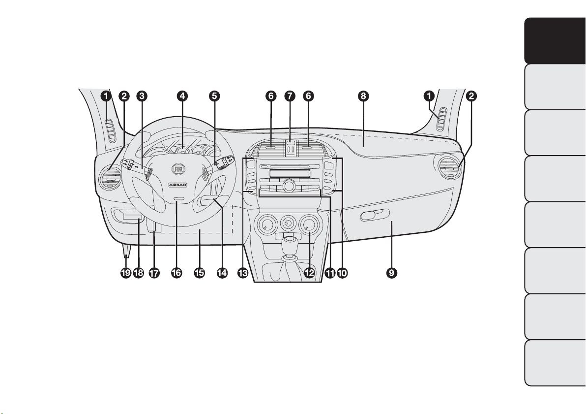
DASHBOARD
The presence and position of the controls, instruments and indicators may vary according to the different
versions.
1. Diffuser for directing air to the side windows - 2. Adjustable and directable air diffuser - 3. Exterior light control lever -
4. Instrument panel - 5. Windscreen wiper/rear window wiper/trip computer control lever - 6. Adjustable and directable
air diffusers - 7. Hazard warning lights switch - 8. Passenger front airbag - 9. Glove compartment - 10. Fog lights/rear
fog lights and menu access/setting switch unit - 11. Radio controls - 12. Heating/ventilation/climate control system
controls - 13. Electric power steering and ASR system (for versions/markets, where present)/front and rear parking
sensors (for versions/markets, where present) on/off switch unit - 14. Ignition key and ignition switch - 15. Driver side
front knee bag (for versions/markets, where provided) - 16. Driver front airbag - 17. Steering wheel locking lever -
18. Fuse box access flap - 19. Bonnet release lever
fig. 1
F0Q0639
3
GETTING TO
KNOW YOUR CAR
SAFETY
STARTING AND
DRIVING
WARNING LIGHTS
AND MESSAGES
IN AN EMERGENCY
SERVICING AND
MAINTENANCE
TECHNICAL
SPECIFICATIONS
INDEX
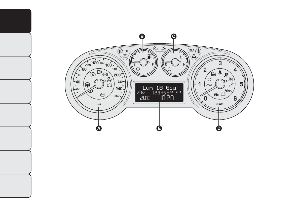
CONTROL PANEL AND
INSTRUMENTS
A. Speedometer B. Fuel level gauge with reserve warning light C. Engine coolant temperature gauge with overheating
warning light D. Rev counter E. Display
fig. 2
F0Q0909
4
GETTING TO
KNOW YOUR CAR
SAFETY
STARTING AND
DRIVING
WARNING LIGHTS
AND MESSAGES
IN AN EMERGENCY
SERVICING AND
MAINTENANCE
TECHNICAL
SPECIFICATIONS
INDEX
SPEEDOMETER
Shows the car speed (speedometer).
REV COUNTER
This indicates the engine rpm.
When the engine is idling, the rev counter may
indicate a gradual or sudden increase of the speed.
This behaviour is standard as it takes place during the
activation of the climate control system or the fan.
It should not be considered as a fault. In these cases,
a slow change in revs is used to protect the battery
charge.
IMPORTANT The electronic injection control system
gradually shuts off the flow of fuel when the engine
is “over-revving” resulting in a gradual loss of engine
power.
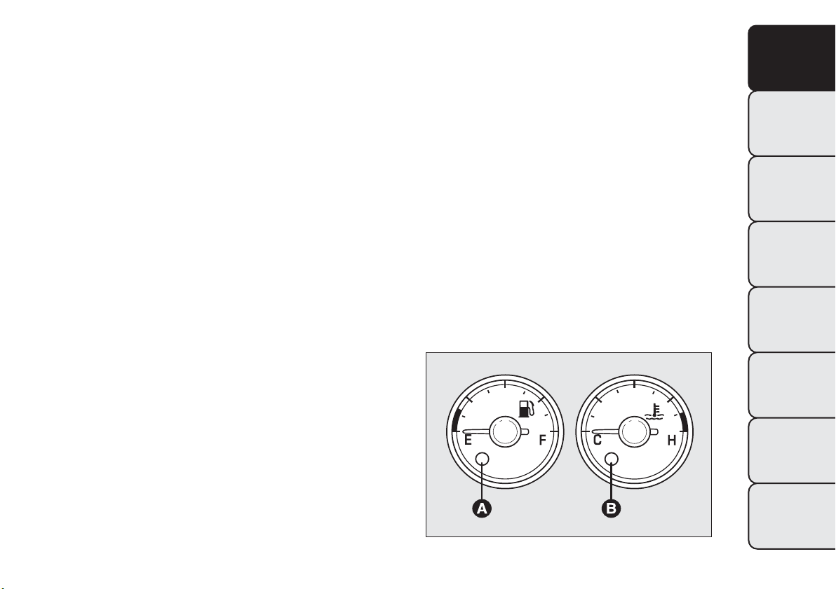
FUEL LEVEL GAUGE
This shows the amount of fuel left in the fuel tank.
Warning light A fig. 3 comes on to indicate that
approximately 8-10 litres of fuel are left in the tank.
E
tank empty
F
tank full (see the instructions provided in the
"Refuelling the car" paragraph in this chapter).
Do not travel with the fuel tank almost empty: any
gaps in fuel delivery could damage the catalytic
converter.
IMPORTANT The needle will point to E and warning
light A fig. 3 will flash to indicate a fault in the
system. Contact a Fiat Dealership to have the system
checked.
fig. 3
F0Q0608
5
GETTING TO
KNOW YOUR CAR
SAFETY
STARTING AND
DRIVING
WARNING LIGHTS
AND MESSAGES
IN AN EMERGENCY
SERVICING AND
MAINTENANCE
TECHNICAL
SPECIFICATIONS
INDEX
ENGINE COOLANT TEMPERATURE
INDICATOR
This shows the temperature of the engine coolant
fluid and starts working when the fluid temperature
exceeds approx. 50°C.
Under normal conditions, the needle assumes
different positions within the scale depending on the
usage conditions.
C
Low engine coolant temperature
H
High engine coolant temperature.
Warning light B fig. 3 may light up (and a message on
the display may appear on certain versions) to
indicate that the coolant fluid temperature is too
high; in this case, stop the engine and contact a Fiat
Dealership.
If the needle for the engine coolant
temperature reaches the red area, stop
the engine immediately and contact a Fiat
Dealership.
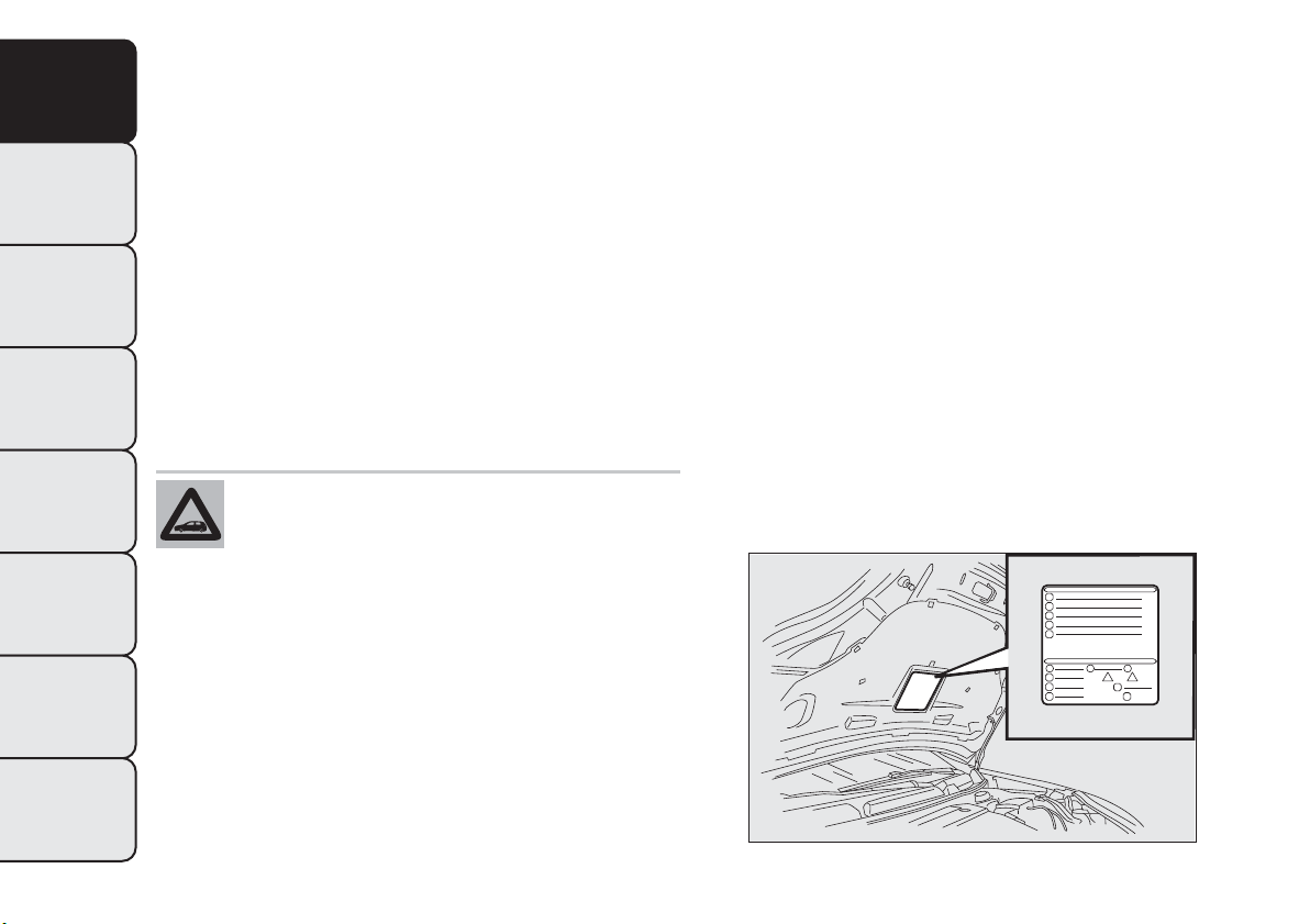
SYMBOLS
Some car components have coloured labels whose
symbols indicate precautions to be observed when
using this component.
A plate summarising these symbols fig. 4 can be
found under the bonnet.
fig. 4
F0Q0640
6
GETTING TO
KNOW YOUR CAR
SAFETY
STARTING AND
DRIVING
WARNING LIGHTS
AND MESSAGES
IN AN EMERGENCY
SERVICING AND
MAINTENANCE
TECHNICAL
SPECIFICATIONS
INDEX
THE FIAT CODE SYSTEM
To further protect your car from theft, it has been
fitted with an engine immobilising system. It is
automatically activated when the ignition key is
removed.
There is an electronic device in each key which can
identify the signal emitted, when the engine is
started, from an aerial built into the ignition switch.
The signal is the "password", different every time the
vehicle is started, through which the control unit
recognises the key and enables starting.
OPERATION
Each time the vehicle is started turning the ignition
key to MAR-ON, the Fiat CODE system control unit
sends an acknowledgement code to the engine
control unit to deactivate the immobiliser. The code
is sent only if the Fiat CODE system control unit
has acknowledged the code received from the key.
Each time the ignition key is turned to STOP, the Fiat
CODE system deactivates the functions of the
engine management control unit.
If, during starting, the code is not correctly
recognised, the
warning light (or symbol on the
display) switches on in the instrument panel.
In this case, turn the key to STOP and then to
MAR-ON; if it is still locked, try again with the other
keys that come with the vehicle. Contact a Fiat
Dealership if you still cannot start the engine.
IMPORTANT Each key has its own code which must
be stored by the system’s control unit. To have
new keys stored, up to a maximum number of eight
keys, contact a Fiat Dealership and be ready to
present all the keys you have in your possession, the
CODE card, a personal identity document and the
car ownership documents. The codes for keys not
presented during the storing procedure will be
deleted to ensure that any keys that are lost or
stolen cannot be used to start the engine.
warning light (or symbol on the display)
on whilst driving
❒ If the
warning light (or symbol in the display)
switches on, this means that the system is running
self-diagnosis (caused, for example, by a voltage
drop).
❒ If the
warning light (or symbol in the display)
stays on, contact a Fiat dealership.
The electronic components inside the key
may be damaged if the key is subjected
to strong shocks.
7
GETTING TO
KNOW YOUR CAR
SAFETY
STARTING AND
DRIVING
WARNING LIGHTS
AND MESSAGES
IN AN EMERGENCY
SERVICING AND
MAINTENANCE
TECHNICAL
SPECIFICATIONS
INDEX
THE KEYS
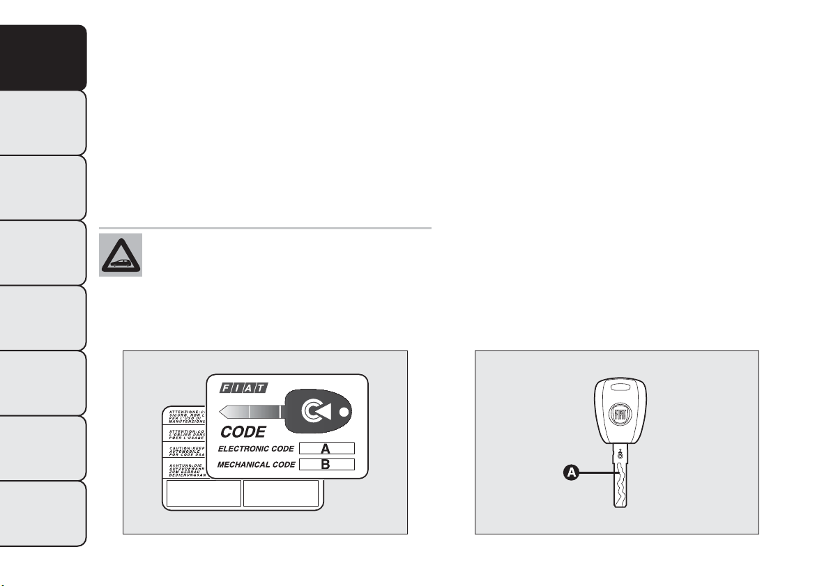
CODE CARD
(for versions/markets, where provided)
A CODE card fig. 5 is provided together with the
vehicle keys. This should be presented to a Fiat
Dealership should you require any duplicate keys.
IMPORTANT In order to ensure complete efficiency
of the electronic devices inside the keys, they should
never be exposed to direct sunlight.
The ignition key and the CODE card must
be handed over to the new owner when
selling the car.
KEY WITHOUT REMOTE CONTROL
(for versions/markets, where provided)
The key is provided with a metal insert A fig. 6,
which operates:
❒ the ignition switch
❒ the door lock
❒ the fuel flap lock/release (on versions supplied with
a lockable plug)
❒ the safe lock device (deactivation only - for
versions/markets, where provided).
To request duplicates of the key, go to a Fiat
Dealership, taking an ID document and the car
ownership documents.
fig. 5
F0Q0001
fig. 6
F0Q0034
8
GETTING TO
KNOW YOUR CAR
SAFETY
STARTING AND
DRIVING
WARNING LIGHTS
AND MESSAGES
IN AN EMERGENCY
SERVICING AND
MAINTENANCE
TECHNICAL
SPECIFICATIONS
INDEX
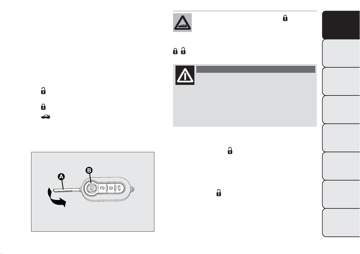
KEY WITH REMOTE CONTROL
The key is provided with a metal insert A fig. 7,
which operates:
❒ the ignition switch
❒ the door lock
❒ the fuel flap lock/unlock
❒ the safe lock device (deactivation only - for
versions/markets, where provided)
Pressing button B opens/closes metal insert A.
Button
remotely unlocks the doors and the
tailgate.
Button
remotely locks the doors and the tailgate.
Button
remotely opens the tailgate.
If the button for locking doors from the
inside is accidentally pressed, only the
doors opened for getting out of the car
are released; the tailgate remains locked. For
system reset, press the lock/release buttons again
/ .
WARNING
Press button B fig. 7 only with the key
away from your body, specifically from
your eyes and from objects which could get
damaged (e.g. your clothes). Do not leave the
key unattended to avoid the button being
accidentally pressed while it is being handled,
e.g. by a child.
Unlocking the doors and the tailgate
Briefly press button
for unlocking the doors and
tailgate with the alarm being switched off at the
same time (for versions/markets, where provided),
timed switching-on of internal roof lights and double
flashing of direction indicators (for versions/markets,
where provided).
Pressing button
for longer than 2 seconds: window
opening.
Doors will be unlocked automatically if the fuel
inertia cut-off switch is activated.
fig. 7
F0Q0255
9
GETTING TO
KNOW YOUR CAR
SAFETY
STARTING AND
DRIVING
WARNING LIGHTS
AND MESSAGES
IN AN EMERGENCY
SERVICING AND
MAINTENANCE
TECHNICAL
SPECIFICATIONS
INDEX
Locking the doors and the tailgate
Briefly press button
for locking the doors and
tailgate with the alarm being switched on at the same
time (for versions/markets, where provided), timed
switching-off of internal roof lights and single flashing
of direction indicators.
Pressing button
for longer than 2 seconds: window
closing. When the button is pressed twice quickly,
the safe lock device is activated (for versions/
markets, where provided) (see "Safe Lock Device"
paragraph hereafter).
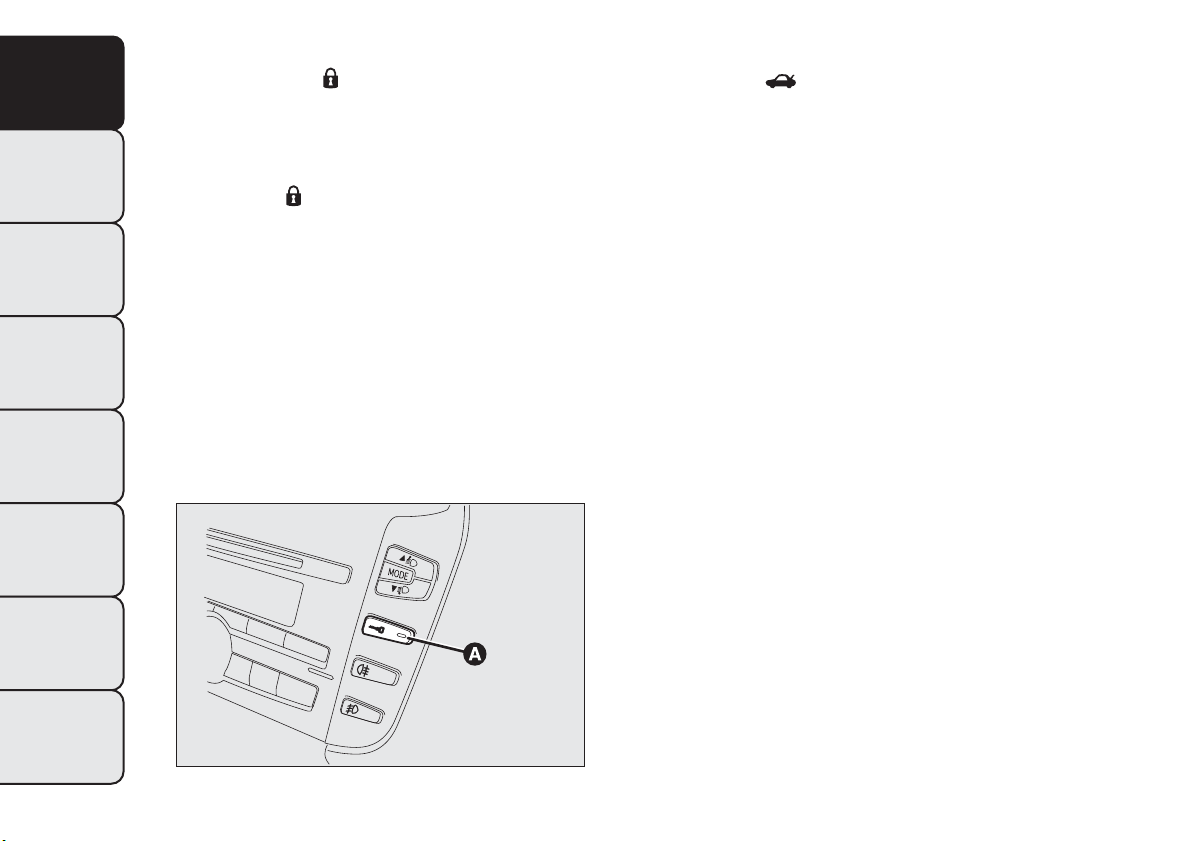
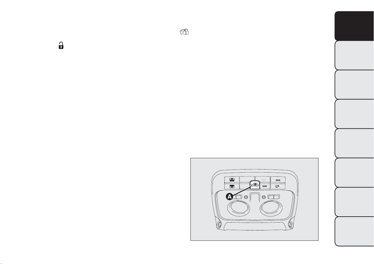
If one or more door are open, the doors will not be
locked. This is signalled by LED A fig. 8 in the central
panel and the direction indicators flashing rapidly. If
the luggage compartment is open, the doors will,
however, be locked.
Opening the tailgate by the remote control
Press button
to release (open) the tailgate
remotely even with the alarm on (for versions/
markets where provided).
The opening of the tailgate is signalled by the
direction indicators flashing twice; when it is closed
there is one flash (only with the alarm on).
If an alarm is fitted, when the tailgate is opened, the
alarm system switches off the volume sensing
protection and the perimeter sensor for the tailgate.
When the tailgate is closed again, the volume sensing
protection and perimeter sensor are restored.
LED indications on central panel
When locking the doors, LED A fig. 8 switches on
for about 3 seconds and then starts flashing
(deterrence function).
If one of the doors or the tailgate are not properly
shut when the doors are being locked, the LED
flashes quickly together with the direction indicators.
fig. 8
F0Q0742
10
GETTING TO
KNOW YOUR CAR
SAFETY
STARTING AND
DRIVING
WARNING LIGHTS
AND MESSAGES
IN AN EMERGENCY
SERVICING AND
MAINTENANCE
TECHNICAL
SPECIFICATIONS
INDEX
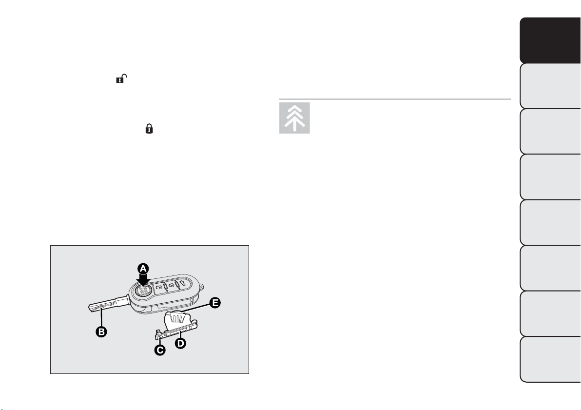
REPLACINGTHE BATTERY IN THE KEY
WITH REMOTE CONTROL
To replace the battery, proceed as follows fig. 9:
❒ press button A and open the metal insert B;
❒ turn screw C to
using a fine bit screwdriver;
❒ take out the battery case D and replace the
battery E making sure that polarities are correct;
❒ refit the battery case D inside the key and lock it
turning the screw C to
.
REQUEST FOR ADDITIONAL REMOTE
CONTROLS
The system can recognise up to 8 remote controls.
Should a new remote control be necessary, contact a
Fiat Dealership, taking with you the CODE card, an
ID document and the car ownership documents.
Used batteries are harmful to the
environment.You can dispose of them
either in the correct containers as
specified by law or by taking them to a Fiat
Dealership, which will deal wi th their disposal.
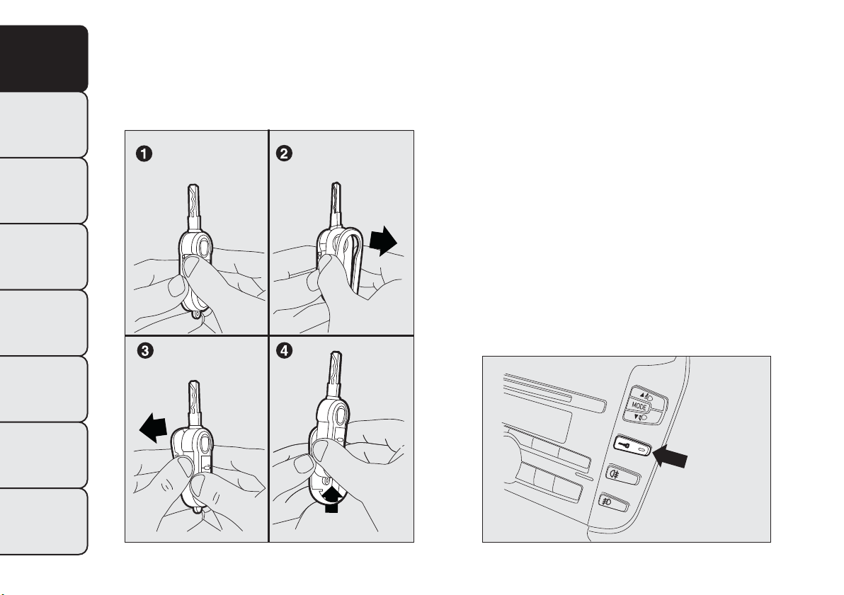
REPLACINGTHE REMOTE CONTROL
COVER
Proceed as shown in figure fig. 10 to replace the
remove control cover.
fig. 9
F0Q0256
11
GETTING TO
KNOW YOUR CAR
SAFETY
STARTING AND
DRIVING
WARNING LIGHTS
AND MESSAGES
IN AN EMERGENCY
SERVICING AND
MAINTENANCE
TECHNICAL
SPECIFICATIONS
INDEX
SAFE LOCK DEVICE
(for versions/markets, where provided)
This safety device inhibits the operation of:
❒ interior handles;
❒ door locking/unlocking button on the central trim
fig. 11;
thereby preventing the opening of the doors from
inside the passenger compartment if there has been
a break in attempt (e.g. a window has been broken).
The safe lock device therefore offers the best
possible protection against break-in attempts. We
recommend engaging it whenever the vehicle is
parked and left unattended.
fig. 10
F0Q0257
fig. 11
F0Q0641
12
GETTING TO
KNOW YOUR CAR
SAFETY
STARTING AND
DRIVING
WARNING LIGHTS
AND MESSAGES
IN AN EMERGENCY
SERVICING AND
MAINTENANCE
TECHNICAL
SPECIFICATIONS
INDEX
WARNING
If the key with remote control battery is
flat, the system can be engaged by
using the metal insert in the door catch as
described previously: in this case, the device only
remains active for the rear doors.
Device activation
The system is automatically enabled on all the doors
by pressing button
twice on the key with remote
control.
Device activation is indicated by 3 flashes of the
direction indicators and a flash of the LED on the
door locking button on the dashboard.
If one or more of the doors is not closed correctly,
the dead lock device will not activate, thus
preventing a person from getting stuck inside the
passenger compartment by entering the car through,
and then closing, the open door.
WARNING
Once the safe lock system is engaged, it
is impossible to o pen the doors from
inside the car.Therefore, before getting out of
the car check that there is no one left on board.
Device deactivation
The system is disabled automatically on every door
when:
❒ unlocking the doors;
❒ by turning the ignition key to the MAR-ON
position.
13
GETTING TO
KNOW YOUR CAR
SAFETY
STARTING AND
DRIVING
WARNING LIGHTS
AND MESSAGES
IN AN EMERGENCY
SERVICING AND
MAINTENANCE
TECHNICAL
SPECIFICATIONS
INDEX
ALARM
(for versions/markets, where provided)
The alarm, in addition to all the remote control
functions described previously, is controlled by the
receiver located under the dashboard near the
fuse box.
ALARM ACTIVATION
The alarm intervenes in the following instances:
❒ when a door, the bonnet or the tailgate is opened
illegally (perimeter protection);
❒ when the ignition system is started up (ignition key
turned to MAR-ON);
❒ cutting of the battery leads;
❒ movement inside the passenger compartment
(volume sensing protection);
❒ anomalous lifting/tilting of the vehicle.
Depending on the market, the activation of the alarm
causes the activation of the siren and the direction
indicators (for about 26 seconds). Alarm tripping and
the number of cycles depend on the sales market.
There is a maximum number of acoustic/visual cycles.
When this is reached the system returns to normal
operation.
The volume sensing and anti-lift protection can be
excluded by adjusting the dedicated control on
the front roof light (see “Volume sensing/Anti-lift
protection”).
IMPORTANT The engine stop function is guaranteed
by the Fiat CODE which is automatically activated
when the key is extracted from the ignition switch.
TURNING THE ALARM ON
With the doors, bonnet and tailgate closed and the
ignition key either turned to STOP or removed,
point the key with remote control towards the
vehicle and press and release button
.
Excluding some markets, the system produces an
acoustic signal (beep) and enables door locking.
The switching on of the alarm is preceded by a
self-diagnosis stage: if a fault is detected, the system
emits a new acoustic signal together with the display
of a message (see “Warning lights and messages”
chapter).
In this case switch off the alarm by pressing
, check
that all the doors, bonnet and tailgate are closed
correctly; then switch the alarm back on by pressing
the
button.
If a door, the bonnet and the tailgate are not
properly shut, they will be excluded from the check
by the alarm system.
If the alarm emits an acoustic signal even when the
doors, bonnet and tailgate are correctly closed, a
failure has occurred in system operation. Go to a Fiat
Dealership.
IMPORTANT The alarm does not come on when the
central locking is activated using the metal insert in
the key.
14
GETTING TO
KNOW YOUR CAR
SAFETY
STARTING AND
DRIVING
WARNING LIGHTS
AND MESSAGES
IN AN EMERGENCY
SERVICING AND
MAINTENANCE
TECHNICAL
SPECIFICATIONS
INDEX
IMPORTANT The alarm is adapted to meet
requirements in various countries.
TURNING THE ALARM OFF
Press button
on the key with remote control.
The following operations are performed (excluding
some versions for specific markets):
❒ direction indicators flash twice;
❒ there are two short acoustic signals (beeps);
❒ doors are unlocked.
IMPORTANT The alarm does not switch off when
the central opening is activated using the metal insert
in the key.
VOLUME SENSING/ANTI-LIFT
PROTECTION
To guarantee the correct operation of the protection
system it is advisable to shut all the side windows
and the sun roof (for versions/markets, where
provided).
If necessary, the function can be turned off (if, for
example, you are leaving an animal in the car) by
pressing button A fig. 12, located in the front roof
light, before activating the alarm itself.
When the function is disabled, this is indicated by the
LED on the button flashing for several seconds. Any
disabling of the volume sensing/anti-lift protection
must be repeated each time the instrument panel is
switched off.
BREAK-IN ATTEMPT INDICATION
Any break-in attempt is indicated by the warning light
(or symbol in the display) lighting up, together
with a message shown in the display (see “Warning
lights and messages” chapter).
DISABLING THE ALARM
To turn the alarm off completely (for example, if the
vehicle is not being used for a long time), the vehicle
must be closed by turning the metal insert of the
key with remote control in the lock.
IMPORTANT If the batteries of the key with remote
control run out or the system fails, the alarm can
be switched off by placing the key in the ignition
switch and turning it to MAR-ON.
fig. 12
F0Q0752
15
GETTING TO
KNOW YOUR CAR
SAFETY
STARTING AND
DRIVING
WARNING LIGHTS
AND MESSAGES
IN AN EMERGENCY
SERVICING AND
MAINTENANCE
TECHNICAL
SPECIFICATIONS
INDEX
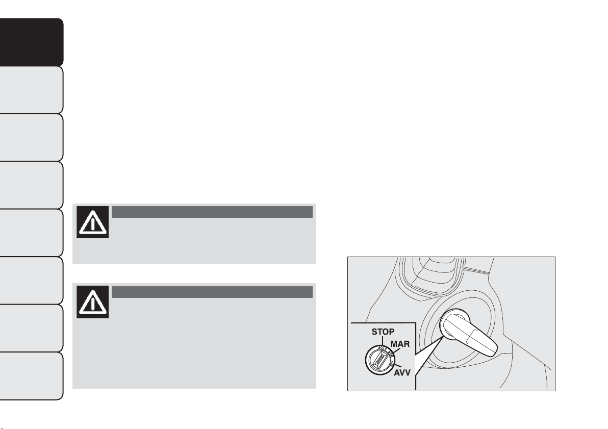
IGNITION SWITCH
The key can be turned to 3 different positionsfig. 13:
❒ STOP: engine off, key can be removed, steering
column locked. Some electrical devices (e.g. radio,
central door locking system, electronic alarm,
etc.) are enabled.
❒ MAR-ON: driving position. All electrical devices
are enabled.
❒ AVV: engine start-up.
The ignition switch is fitted with a safety system that
requires the ignition key to be turned back to STOP
if the engine does not start, before the starting
operation can be repeated.
WARNING
If the ignition switch is tampered with
(e.g. attempted theft), have it checked
over by a Fiat Dealership before driving again.
WARNING
Always remove the key when you leave
your car to prevent someone from
accidentally operating the controls. Remember
to engage the handbrake. If the car is parked on
uphill slope, engage the first gear; if the car is
facing downhill, engage the reverse gear. Never
leave children unattended in the car.
STEERING LOCK
Engagement
When at STOP, remove the key and turn the steering
wheel until it locks.
Disengagement
Move the steering wheel slightly as you turn the
ignition key to MAR-ON.
IMPORTANT In some parking conditions (e.g.:
wheels turned) the effort required to move the
steering wheel and disengage the steering lock may
be increased.
fig. 13
F0Q0642
16
GETTING TO
KNOW YOUR CAR
SAFETY
STARTING AND
DRIVING
WARNING LIGHTS
AND MESSAGES
IN AN EMERGENCY
SERVICING AND
MAINTENANCE
TECHNICAL
SPECIFICATIONS
INDEX
WARNING
It is absolutely forbidden to carry out
any aftermarket operation involving
steering system or steering column
modifications (e.g.: installation of anti-theft
device) that could badly affect performance and
safety, invalidate the warranty and also result
in non-compliance of the car with type-
approval requirements.
WARNING
Never remove the key while the car is
moving.The steering wheel will lock
as soon as it is turned.This holds true for cars
being towed as well.
DISPLAY
The car is equipped with a multifunction display that,
according to the previously applied settings, will
show useful driving information.
When one of the front doors is opened, the display
is activated, showing the time and mileage for a
few seconds.
Note With a low outside temperature (below 0°C)
it may take longer than normal for information to
appear on the display.
17
GETTING TO
KNOW YOUR CAR
SAFETY
STARTING AND
DRIVING
WARNING LIGHTS
AND MESSAGES
IN AN EMERGENCY
SERVICING AND
MAINTENANCE
TECHNICAL
SPECIFICATIONS
INDEX
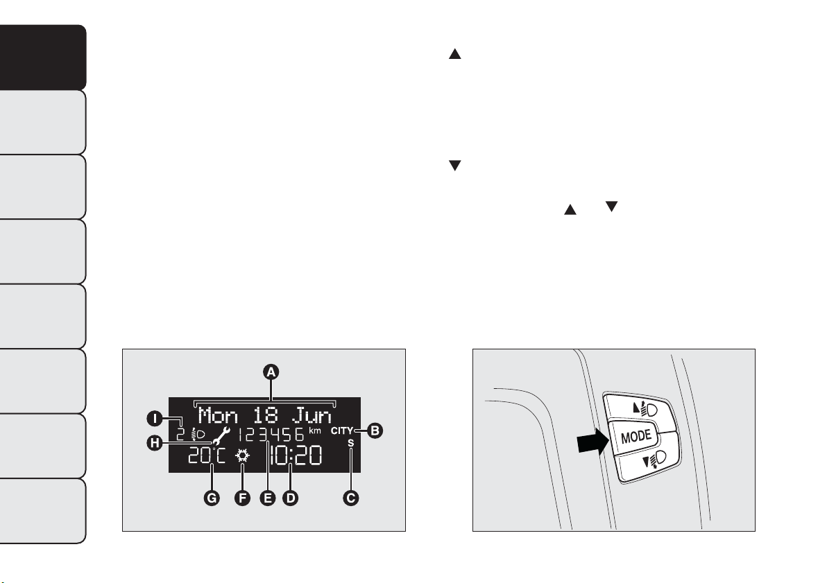
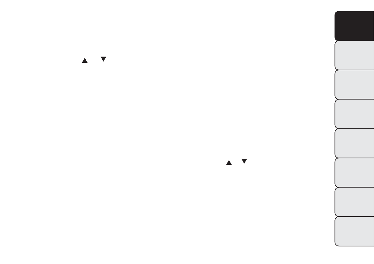
MULTIFUNCTION DISPLAY “STANDARD”
SCREEN
The standard screen fig. 14 can display the following
information:
A
Date
B
Possible Dualdrive electric power steering
engagement
C
Sport driving mode indication (for versions/
markets, where provided)
D
Time
E
Milometer (display of distance travelled in
kilometres/miles)
F
Possible ice on the road indication
G
Outside temperature
H
Scheduled servicing interval
I
Headlight alignment position (only with dipped
headlights on)
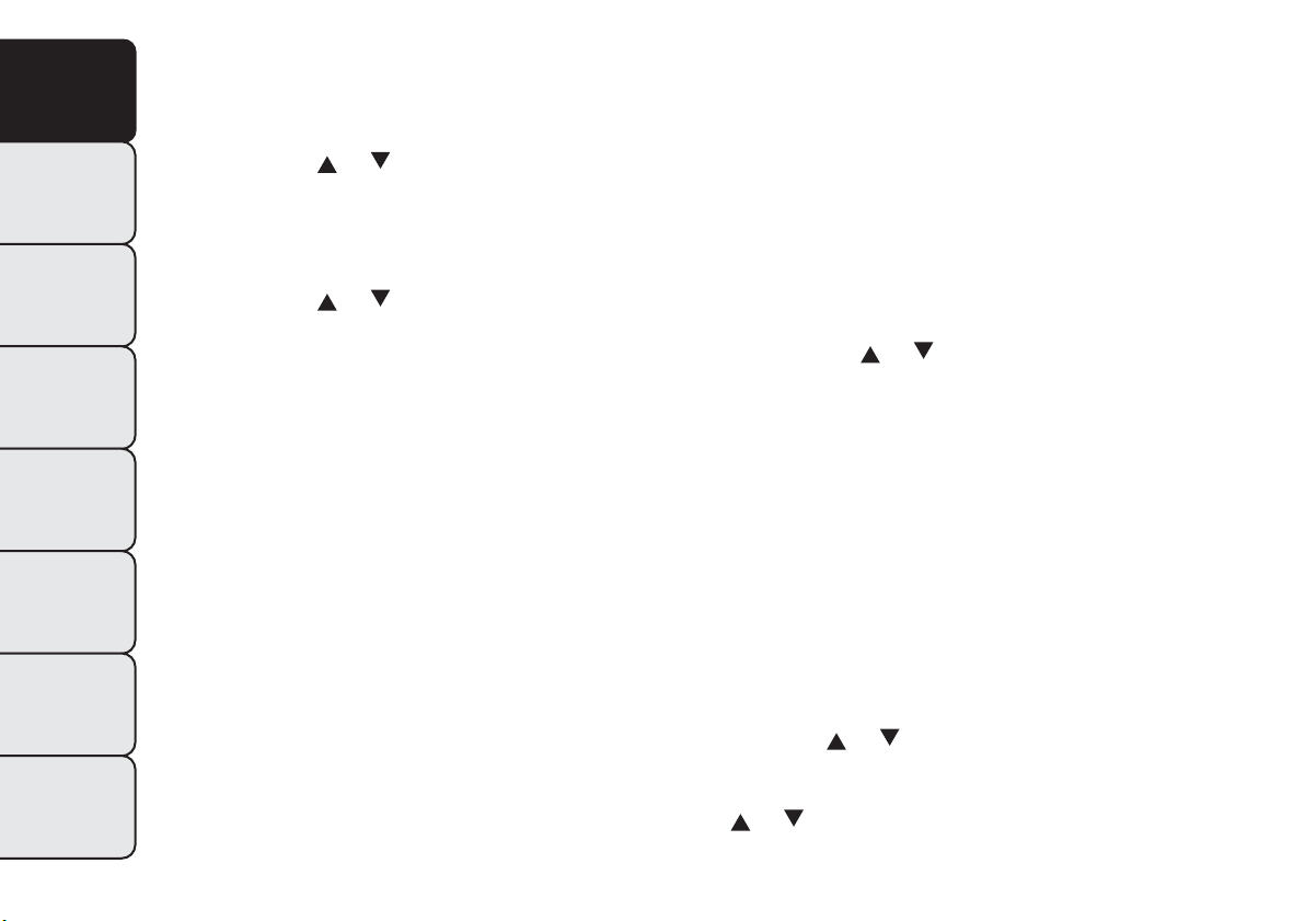
CONTROL BUTTONS
fig. 15:
to scroll through the screen and the
options upwards or to increase the value
displayed.
MODE:
press briefly to access the menu and/or go
to next screen or confirm the desired
selection. Hold down to go back to the
standard screen.
:
to scroll through the screen and the options
downwards or to decrease the value displayed.
IMPORTANT The
and buttons activate different
functions according to the following situations:
❒ within the menu, they allow you to scroll up and
down through the options;
❒ during settings operations, they increase or
decrease values.
fig. 14
F0Q3245
fig. 15
F0Q0643
18
GETTING TO
KNOW YOUR CAR
SAFETY
STARTING AND
DRIVING
WARNING LIGHTS
AND MESSAGES
IN AN EMERGENCY
SERVICING AND
MAINTENANCE
TECHNICAL
SPECIFICATIONS
INDEX
IMPORTANT When one of the front doors is
opened, the display is activated, showing the time
and mileage for a few seconds.
SETUP MENU
The menu comprises a series of functions which can
be selected using the
and buttons to access
the different selection and setting (setup) operations
indicated below.
Some options have a submenu.
The Setup Menu can be activated by pressing the
MODE button briefly.
If the Radionavigator is installed, only the following
functions can be adjusted/set from the instrument
panel: "Lighting", “Speed beep”, "Headlight sensor"
(for versions/markets, where provided), "Belt buzzer"
and "Passenger airbag". The other functions are
shown on the Radionavigator display. You can set and
adjust them there.
The menu comprises the following options:
❒ LIGHTING
❒ SPEED BEEP
❒ HEADLIGHT SENSOR (for versions/markets,
where provided)
❒ TRIP B ACTIVATION/DATA
❒ SET TIME
❒ SET DATE
❒ FIRST PAGE (for versions/markets, where
provided)
❒ SEE RADIO
❒ AUTOCLOSE
❒ UNITS OF MEASUREMENT
❒ LANGUAGE
❒ WARNINGS VOLUME
❒ BUTTON VOLUME
❒ SEAT BELT BEEP/BUZZ.
❒ SERVICE
❒ AIRBAG/PASSENGER BAG
❒ CORNERING LIGHTS (for versions/markets,
where provided)
❒ EXIT MENU
Selecting an option from the main menu
without a submenu:
❒ briefly press the MODE button to select the main
menu option that needs to be changed;
❒ press buttons
or (with single presses) to
select the new setting;
❒ briefly press the MODE button to store the new
setting and at the same time go back to the
previously selected menu option.
19
GETTING TO
KNOW YOUR CAR
SAFETY
STARTING AND
DRIVING
WARNING LIGHTS
AND MESSAGES
IN AN EMERGENCY
SERVICING AND
MAINTENANCE
TECHNICAL
SPECIFICATIONS
INDEX
Selecting an option from the main menu with
a submenu:
❒ briefly press the MODE button to display the first
submenu option;
❒ press buttons
or (with single presses) to
scroll through all the submenu options;
❒ briefly press the MODE button to select the
displayed submenu option and to open the
relevant settings menu;
❒ press buttons
or (with single presses) to
select the new setting for this submenu option;
❒ briefly press the MODE button to store the new
setting and at the same time go back to the
previously selected submenu option.
MENU ITEMS
Lighting (Interior light adjustment)
With the side lights on, this function is used to set
the brightness of the instrument panel, radio
controls and dual zone automatic climate control
system controls (for versions/markets where
provided) to 8 levels.
Proceed as follows to adjust the brightness:
❒ briefly press the MODE button: the previously set
level flashes on the display;
❒ press button
or to set the required brightness
level;
❒ briefly press the MODE button to return to the
menu screen or hold the button down to return
to the standard screen without storing.
Speed Beep (Speed limit)
This function is used to set the car speed limit (km/h
or mph); the driver is immediately alerted when
this limit is exceeded (see section “Warning lights
and messages”).
To set the desired speed limit, proceed as follows:
❒ press the MODE button briefly, the display shows
the dedicated message;
❒ press the
or button to select speed limit
activation (On) or deactivation (Off);
❒ if the function has been activated (On), press the
or buttons to select the desired speed limit
and then press MODE to confirm.
20
GETTING TO
KNOW YOUR CAR
SAFETY
STARTING AND
DRIVING
WARNING LIGHTS
AND MESSAGES
IN AN EMERGENCY
SERVICING AND
MAINTENANCE
TECHNICAL
SPECIFICATIONS
INDEX
IMPORTANT Setting is possible between 30 and 200
km/h, or 20 and 125 mph, according to the
previously set unit. See the "Units of measurement
adjustment (Units of measurement)" paragraph
described below. The setting will increase/decrease
by 5 units each time button
/ is pressed. Hold
down the
/ button to automatically increase/
decrease the setting rapidly. Complete the
adjustment with single presses of the button when
you approach the desired value.
Briefly press the MODE button to return to the
menu screen or hold the button down to return to
the standard screen without storing.
To cancel the setting, proceed as follows:
❒ briefly press button MODE, (On) will flash on the
display;
❒ press button
, (Off) will flash on the display;
❒ press the MODE button briefly to return to the
menu screen or hold the button down to return
to the standard screen without storing.
Headlight sensor (Automatic headlight/dusk
sensor sensitivity adjustment)
(for versions/markets, where provided)
This function is used to turn the headlights on or off
according to external lighting conditions.
The headlight sensor sensitivity can be adjusted
according to 3 levels (level 1 = minimum sensitivity,
level2=average sensitivity, level 3 = maximum
sensitivity). The higher the sensitivity set, the lesser
is the external light variation needed to switch
the lights on (e.g. with a setting on level 3 at sunset
the headlights come on in advance in relation to
levels 1 and 2).
Proceed as follows to set the desired adjustment:
❒ briefly press the MODE button: the previously set
level flashes on the display;
❒ press
or to make your choice;
❒ press the MODE button briefly to return to the
menu screen or hold the button down to return
to the standard screen without storing.
Cornering lights (Activation/deactivation of
“Cornering lights”)
(fog light with cornering function)
(for versions/markets where provided)
This function activates/deactivates the cornering
lights.
To activate/deactivate (On/Off) the lights, proceed as
follows:
❒ press the MODE button briefly, the display will
show “On” or “Off” flashing depending on the
previous setting;
❒ press
or to make your choice;
❒ briefly press the MODE button to return to the
menu screen or hold the button down to return
to the standard screen without storing.
21
GETTING TO
KNOW YOUR CAR
SAFETY
STARTING AND
DRIVING
WARNING LIGHTS
AND MESSAGES
IN AN EMERGENCY
SERVICING AND
MAINTENANCE
TECHNICAL
SPECIFICATIONS
INDEX

Activation/Trip B data (Activating Trip B)
This function can be used to activate (On) or
deactivate (Off) the Trip B display (partial trip). For
further information see “Trip computer” in this
section.
Proceed as follows to switch the function on/off:
❒ briefly press the MODE button: On or Off flashes
on the display (according to the previous setting);
❒ press
or to make your choice;
❒ briefly press the MODE button to return to the
menu screen or hold the button down to return
to the standard screen without storing.
Time adjustment (Clock adjustment)
This function enables to set the clock through two
submenus: “Time” and “Format”.
To carry out the adjustment, proceed as follows:
❒ briefly press the MODE button and two
submenus, "Time" and "Format", are displayed;
❒ press the
or button to switch between the
two submenus;
❒ once you have selected the submenu to be
changed, press the MODE button briefly;
❒ when you select “Time”, briefly pressing the
MODE button makes the hours flash on the
display;
❒ press the
or button to make the adjustment;
❒ briefly press the MODE button: “minutes” starts
flashing on the display;
❒ press the button
or for setting.
IMPORTANT The setting will increase or decrease
by one unit each time the button
or is pressed.
Hold down the button to increase/decrease the
setting rapidly and automatically. Complete the
adjustment with single presses of the button when
you approach the desired value.
If you enter the "Format" submenu, pressing the
MODE button briefly makes the display format flash
on the display;
❒ Press button
or to select “24h” or “12h”.
❒ when you have made the adjustment, briefly press
the MODE button to go back to the submenu
screen or hold the button down to go back to the
main menu screen without storing.
❒ hold down the MODE button again to return to
the standard screen or to the main menu
according to where you are in the menu.
When you have made the adjustment, briefly press
the MODE button to go back to the submenu screen
or hold the button down to go back to the main
menu screen without storing.
22
GETTING TO
KNOW YOUR CAR
SAFETY
STARTING AND
DRIVING
WARNING LIGHTS
AND MESSAGES
IN AN EMERGENCY
SERVICING AND
MAINTENANCE
TECHNICAL
SPECIFICATIONS
INDEX

Set date (Setting the date)
Using this function it is possible to update the date
(day - month - year).
Proceed as follows to start the update:
❒ briefly press the SET button: the “year” will flash
on the display;
❒ press the
or button to make the adjustment;
❒ briefly press the SET button: the “month” will flash
on the display;
❒ press the
or button to make the adjustment;
❒ briefly press the SET button: the “day” will flash on
the display;
❒ press the button
or for setting.
IMPORTANT The setting will increase or decrease
by one unit each time the button
or is pressed.
Hold down the button to increase/decrease the
setting rapidly and automatically. Complete the
adjustment with single presses of the button when
you approach the desired value.
Briefly press the MODE button to return to the
menu screen or hold the button down to return to
the standard screen without storing.
First page (display of information on the main
screen)
(for versions/markets, where provided)
This function allows you to choose the information
you would like to display on the main screen.
You can choose to display the date or the
turbocharger boost pressure.
To make your choice, proceed as follows:
❒ briefly press the MODE button: "First page" will
appear on the display;
❒ briefly press the MODE button again to display the
"Date" and "Engine info" options;
❒ press
or to select the information you wish to
see on the main page of the display;
❒ press the MODE button briefly to return to the
menu screen or hold the button down to return
to the standard screen without storing.
When the key is turned to MAR-ON and the initial
check stage is over, the display will show the
information set previously via the “First page” menu
function.
23
GETTING TO
KNOW YOUR CAR
SAFETY
STARTING AND
DRIVING
WARNING LIGHTS
AND MESSAGES
IN AN EMERGENCY
SERVICING AND
MAINTENANCE
TECHNICAL
SPECIFICATIONS
INDEX
See radio (Audio information display)
With this function the display shows information
about the sound system.
❒ Radio: selected radio station frequency or RDS
message, automatic tuning activation or
AutoSTore;
❒ Audio CD, MP3 CDs: track number;
❒ CD Changer: CD number and track number;
To show the radio information on the display (On)
or clear it (Off), proceed as follows:
❒ briefly press the MODE button, the display will
show "On" or "Off" flashing depending on the
previous setting;
❒ press
or to make your choice;
❒ briefly press the MODE button to return to the
menu screen or hold the button down to return
to the standard screen without storing.
Autoclose (Automatic central locking with
the car in motion)
When activated (On), this function locks the doors
automatically when the vehicle speed exceeds 20
km/h.
Proceed as follows to activate or deactivate this
function:
❒ briefly press the MODE button to display a
submenu;
❒ briefly press the MODE button: "On" or "Off"
flashes on the display according to the previous
setting;
❒ press
or to make your choice;
❒ press the MODE button briefly to return to the
submenu screen or hold the button down to
return to the main menu screen without storing;
❒ hold down the MODE button again to return to
the standard screen or to the main menu
according to where you are in the menu.
Unit of measurement (Setting the unit of
measurement)
With this function it is possible to set the units
through three submenus: "Distances",
"Consumption" and "Temperature". To set the
desired unit, proceed as follows:
❒ briefly press the MODE button to display the
three submenus;
❒ press button
or to navigate through the three
submenus;
❒ once you have selected the submenu to be
changed, press the MODE button briefly;
❒ when you select the “Distances” submenu, briefly
pressing the MODE button makes the display
show “km” or “mi” depending on the previous
setting;
24
GETTING TO
KNOW YOUR CAR
SAFETY
STARTING AND
DRIVING
WARNING LIGHTS
AND MESSAGES
IN AN EMERGENCY
SERVICING AND
MAINTENANCE
TECHNICAL
SPECIFICATIONS
INDEX
❒ press or to make your choice;
❒ when you select the “Consumption” submenu,
pressing the MODE button makes "km/l", "l/100
km" or "mpg" appear on the display depending on
the previous setting;
If the set distance unit is "km", the fuel consumption
unit will be displayed in km/l or l/100 km.
If the set distance unit is “mi” the fuel consumption
unit will be displayed in “mpg”.
❒ press
or to make your choice;
❒ when you enter the “Temperature” submenu,
briefly pressing the MODE button makes "°C" or
"°F" appear on the display depending on the
previous setting;
❒ press
or to make your choice;
When you have made the adjustment, briefly press
the MODE button to go back to the submenu screen
or hold the button down to go back to the main
menu screen without storing.
Hold down the MODE button again to return to the
standard screen or to the main menu according to
where you are in the menu.
Language (Language selection)
Display messages can be shown in different
languages: Italian, German, English, Spanish, French,
Portuguese and Dutch.
To set the desired language, proceed as follows:
❒ briefly press the MODE button: the previously set
language starts flashing on the display;
❒ press
or to make your choice;
❒ briefly press the MODE button to return to the
menu screen or hold the button down to return
to the standard screen without storing.
Warnings volume (Adjusting the failure/
warning acoustic signal volume)
With this function the volume of the buzzer which
accompanies the display of any failure/warning can be
adjusted to 8 levels.
To set the desired volume, proceed as follows:
❒ press the MODE button briefly, making the display
flash the previously set volume "level";
❒ press the
or button to make the adjustment;
❒ briefly press the MODE button to return to the
menu screen or hold the button down to return
to the standard screen without storing.
25
GETTING TO
KNOW YOUR CAR
SAFETY
STARTING AND
DRIVING
WARNING LIGHTS
AND MESSAGES
IN AN EMERGENCY
SERVICING AND
MAINTENANCE
TECHNICAL
SPECIFICATIONS
INDEX
Button volume (adjusting the button volume)
This function allows the volume of the acoustic
signal that accompanies MODE,
and button
presses to 8 levels
To set the desired volume, proceed as follows:
❒ press the MODE button briefly, making the display
flash the previously set volume "level";
❒ press the
or button to make the adjustment;
❒ press the MODE button briefly to return to the
menu screen or hold the button down to return
to the standard screen without storing.
Seat belt buzzer (Buzzer activation for SBR
indication)
This function can be displayed only after a Fiat
Dealership has deactivated the SBR system (see the
“Safety” section in the “SBR system” paragraph).
To reactivate this function, proceed as follows:
❒ briefly press the MODE button, the display shows
"Off" flashing. Press the
or button and "On"
will appear;
❒ briefly press the MODE button to return to the
submenu screen or hold the button down to
return to the main menu screen without storing.
Service (Scheduled servicing)
Using this function you can display information about
the mileage intervals for car servicing.
To consult this information, proceed as follows:
❒ briefly press the MODE button: the display shows
when servicing is due in km or mi according to the
previous setting (see paragraph “Units of
measurement”);
❒ briefly press the MODE button to go back to the
menu screen or hold the button down to go back
to the standard screen.
Note According to the “Scheduled Servicing Plan”,
the car must be serviced every 35,000 km (or
equivalent value in miles). This message is displayed
automatically - when the key is turned to MAR-ON -
2,000 km (or equivalent value in miles) before these
deadlines and reappears every 200 km (or equivalent
value in miles). Below 200 km servicing indications
are more frequent. The indication will appear in
kilometres or miles depending on the unit of
measurement settings. When one of the next
scheduled deadlines is approaching, the word
“Service” will appear on the display, followed by the
number of kilometres or miles left, when the key
is turned to MAR-ON. Contact a Fiat Dealership.
The operations in the “Scheduled servicing plan” will
be performed and the message will be reset.
26
GETTING TO
KNOW YOUR CAR
SAFETY
STARTING AND
DRIVING
WARNING LIGHTS
AND MESSAGES
IN AN EMERGENCY
SERVICING AND
MAINTENANCE
TECHNICAL
SPECIFICATIONS
INDEX

Airbag/Passenger bag
This function is used to activate/deactivate the
passenger side airbag.
Proceed as follows:
❒ press the MODE button and, after the message
"Bag pass: Off" (to deactivate) or "Bag pass: On"
(to activate) is displayed by pressing the
and
buttons, press the MODE button again;
❒ a confirmation request message will appear on the
display;
❒ by pressing the
or buttons, select ("Yes") (to
confirm activation/deactivation) or ("No") (to
cancel);
❒ press the MODE button briefly and a message
confirming the selection will be displayed, then you
will return to the menu screen, or hold the
button down to return to the standard screen
without storing.
Exit menu
The last function closing the cycle of settings listed in
the menu screen.
Press the MODE button briefly to return to the
standard screen without storing.
Press the
button to go back to the first menu
option ("Speed Beep").
27
GETTING TO
KNOW YOUR CAR
SAFETY
STARTING AND
DRIVING
WARNING LIGHTS
AND MESSAGES
IN AN EMERGENCY
SERVICING AND
MAINTENANCE
TECHNICAL
SPECIFICATIONS
INDEX

TRIP COMPUTER
General information
The Trip computer is used to display information on
car operation when the key is turned to MAR-ON.
Two separate trips, called “Trip A” and “Trip B”,
are provided to monitor the entire mission (journey)
in a reciprocally independent manner.
Both functions can be reset (reset - start of a new
journey).
“Trip A” is used to display the figures relating to:
❒ Range
❒ Distance covered
❒ Average consumption
❒ Instantaneous consumption
❒ Average speed
❒ Trip time (driving time).
“Trip B” is used to display the figures relating to:
❒ Distance travelled B
❒ Average consumption B
❒ Average speed B
❒ Trip time B (driving time).
Note The “Trip B” function may be disabled (see
“Activating Trip B”). The “Range” and “Instant
consumption" parameters cannot be reset.
Values displayed
Range
This indicates the approximate distance which can be
travelled with the amount of fuel present in the
tank.“----”will appear on the display in the
following cases:
❒ range value lower than 50 km (or 30 mi)
❒ car parked with engine running for an extended
period.
IMPORTANT The range value variation can be
affected by several factors: driving style, type of route
(motorway, urban, mountain roads, etc.), conditions
of use (load, tyre pressures, etc.). Trip planning
must therefore take the above into account.
Distance covered
Shows the distance covered since the start of the
new journey.
Average consumption
Shows the approximate average fuel consumption
since the start of the new journey.
Instantaneous consumption
This indicates the fuel consumption. The value is
constantly updated. The display will show “----”if
the car is parked with the engine running.
28
GETTING TO
KNOW YOUR CAR
SAFETY
STARTING AND
DRIVING
WARNING LIGHTS
AND MESSAGES
IN AN EMERGENCY
SERVICING AND
MAINTENANCE
TECHNICAL
SPECIFICATIONS
INDEX
Average speed
This shows the average car speed as a function of the
overall time elapsed since the start of the new
journey.
Trip time
The time elapsed since the start of a new journey.
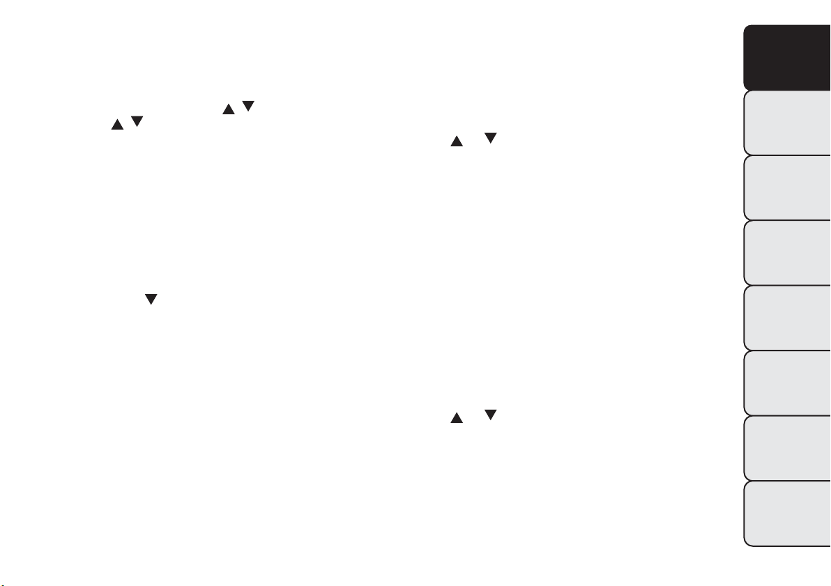
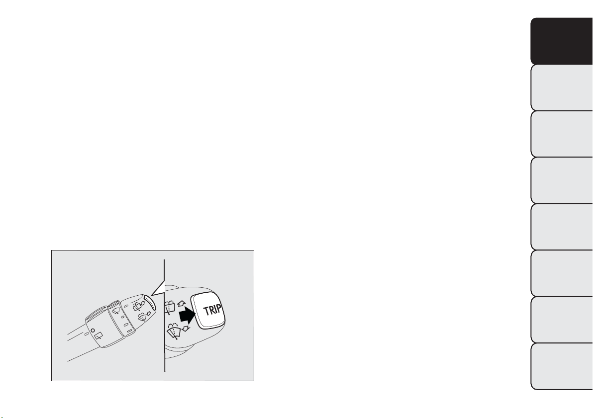
TRIP BUTTON
The TRIP button is located on the right hand
stalkfig. 16. With the ignition key turned to
MAR-ON, this button allows you to view the
previously described parameters and also zero them
to begin a new mission:
❒ short press: display various values;
❒ long press: reset values and start a new journey.
New mission
This begins after a reset:
❒ “manual” resetting by the user, by pressing the
relevant button;
❒ automatically when the distance travelled reaches
99,999.9 km or when the journey time reaches
99.59 (99 hours and 59 minutes);
❒ after disconnection/reconnection of the battery.
IMPORTANT The reset operation when “Trip A” or
“Trip B” details are being displayed only resets the
values associated with the function displayed.
Start of journey procedure
With ignition key at MAR, press and hold down the
TRIP button for more than 2 seconds to reset.
Exiting the Trip Function
You can automatically exit the TRIP function once all
the values have been displayed or by holding the
MODE button down for more than 1 second.
fig. 16
F0Q0647
29
GETTING TO
KNOW YOUR CAR
SAFETY
STARTING AND
DRIVING
WARNING LIGHTS
AND MESSAGES
IN AN EMERGENCY
SERVICING AND
MAINTENANCE
TECHNICAL
SPECIFICATIONS
INDEX
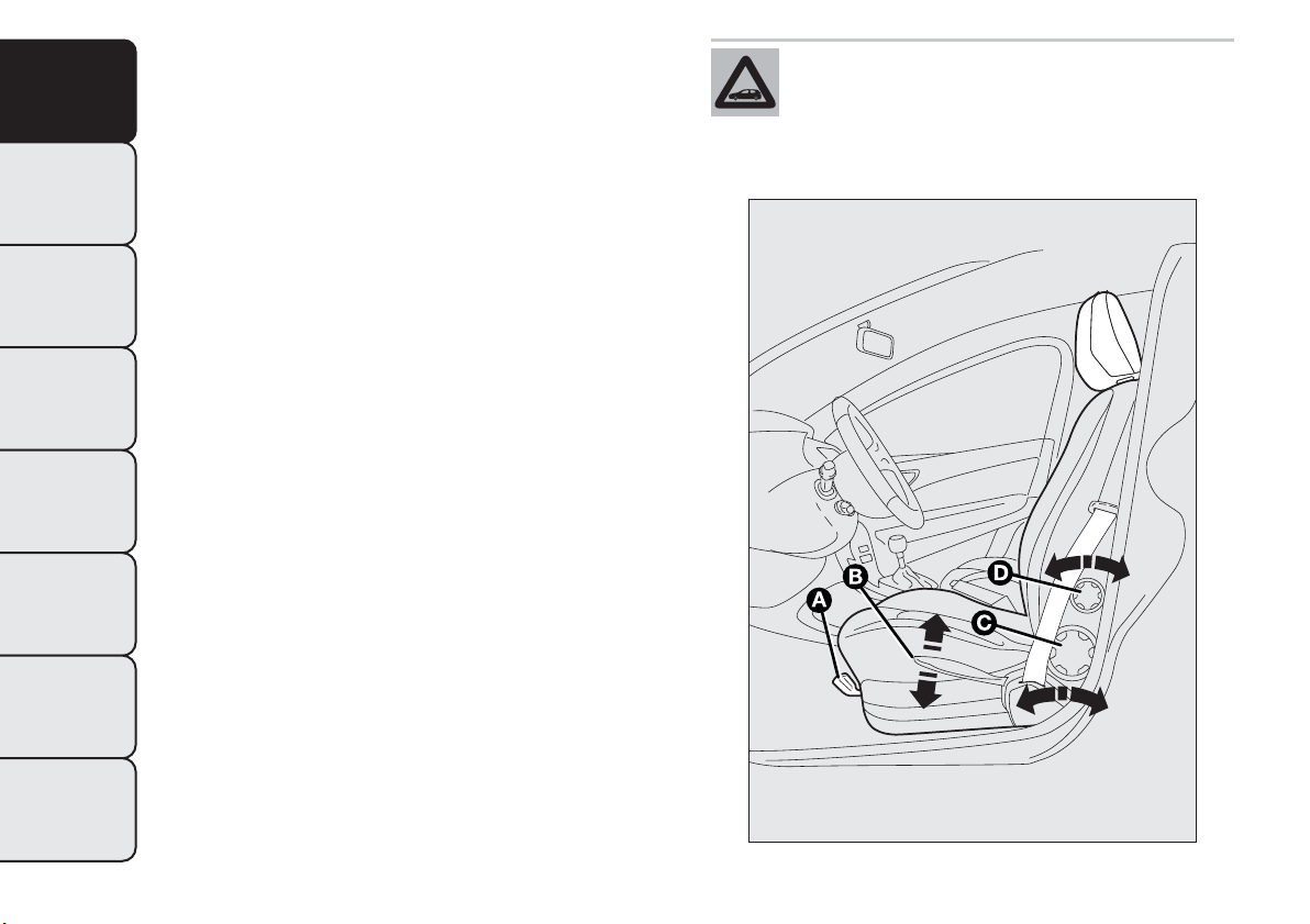
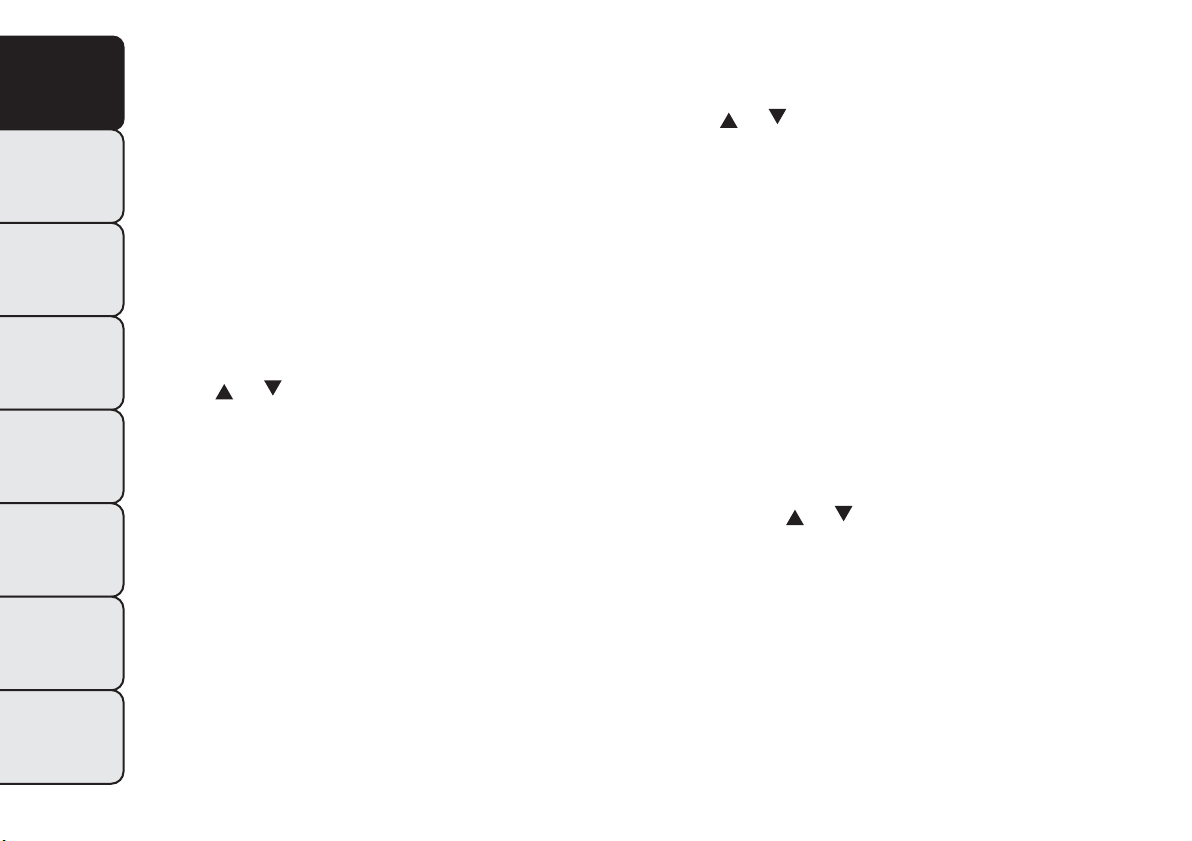
SEATS
FRONT SEATS WITH MANUAL
ADJUSTMENT
Longitudinal adjustment fig. 17
Lift lever A (on the seat internal side) and push the
seat forwards or backwards: in driving position
your arms should rest on the rim of the steering
wheel.
Height adjustment fig. 17
Move lever B upwards or downwards to achieve the
required height.
IMPORTANT Adjustment must be carried out only
when seated in the relevant seat.
Backrest angle adjustment fig. 17
Turn knob C.
Lumbar adjustment fig. 17
(for versions/markets, where provided)
The position of the back against the seat backrest
can be adjusted by turning knob D.
All adjustments must be made with the
car stationary.
fig. 17
F0Q0654
30
GETTING TO
KNOW YOUR CAR
SAFETY
STARTING AND
DRIVING
WARNING LIGHTS
AND MESSAGES
IN AN EMERGENCY
SERVICING AND
MAINTENANCE
TECHNICAL
SPECIFICATIONS
INDEX
The fabric upholstery of your car has
been designed to wi thstand wear deriving
from common use of the car.You are
however recommended to avoid strong and/or
continuous scratching wi th clothing accessories
such as metal buckles , studs,Velcro fastenings and
the like, as these items cause stress of the cover
fabric that could lead to yarn breaking and
damage the upholstery.
Once you have released the adjustment
lever, always check that the seat is locked
on the guides by trying to move it back
and forth. If the seat is not locked into place, it
may unexpectedly slide and cause the driver
to lose control of the car.
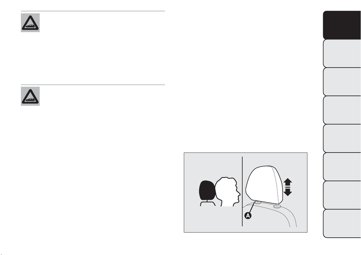
HEAD RESTRAINTS
FRONT
These are height-adjustable and lock into place
automatically.
❒ Upward adjustment: lift the head restraint until it
clicks into place.
❒ Downward adjustment: press button A fig. 18 and
lower the head restraint.
On some versions the front head restraints are
equipped with an “Anti-Whiplash” device, which
reduces the distance between head and head
restraint in the event of a rear shunt, thus mitigating
the “whiplash” effect.
The “Anti-Whiplash” type front head restraints may
move when the backrest is pressed by the occupant's
torso or hand. This behaviour is caused by the
system and should not be considered a malfunction.
fig. 18
F0Q0655
31
GETTING TO
KNOW YOUR CAR
SAFETY
STARTING AND
DRIVING
WARNING LIGHTS
AND MESSAGES
IN AN EMERGENCY
SERVICING AND
MAINTENANCE
TECHNICAL
SPECIFICATIONS
INDEX
WARNING
Head restraints must be adjusted so that
the head, rather than the neck , rests on
them. Only when they are adjusted in this
manner can they serve their intended purpose.
WARNING
To take best advantage of the protection
provided by the head restraint, adjus t
the seat backrest so that you are sitting up
straight and your head is as close to the head
restraint as possible.
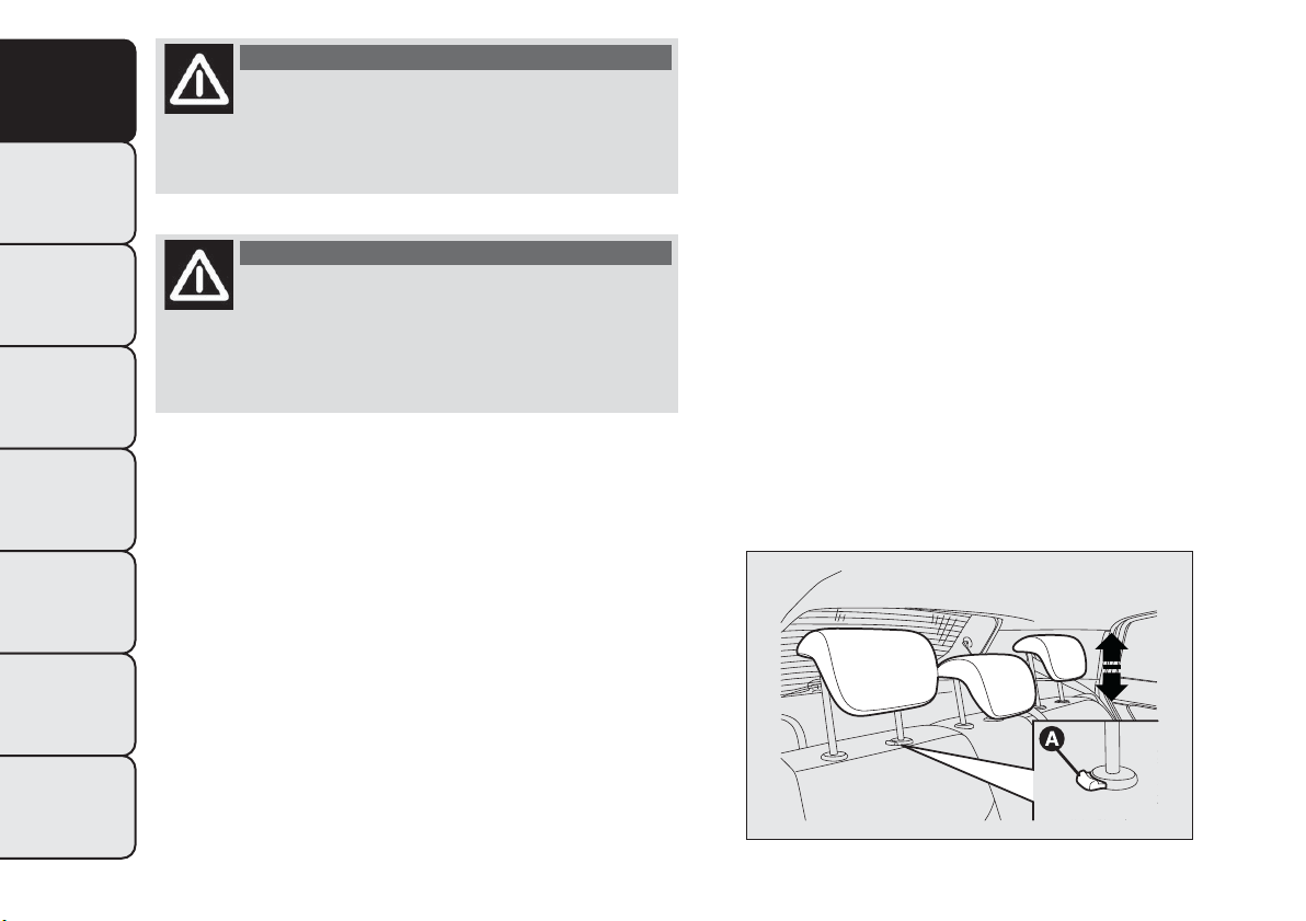
REAR
The car is equipped with two head restraints for the
side seats and on some versions a head restraint is
also provided for the central seat.
To extract the head restraints, raise them until you
hear the click (which indicates they are in the
position of use, 'fully raised').
To bring them back to the position of non-use, press
button A fig. 19 and push them down into the
backrest.
IMPORTANT If the rear seats are used, always set
the head restraints in the "fully raised" position.
fig. 19
F0Q0656
32
GETTING TO
KNOW YOUR CAR
SAFETY
STARTING AND
DRIVING
WARNING LIGHTS
AND MESSAGES
IN AN EMERGENCY
SERVICING AND
MAINTENANCE
TECHNICAL
SPECIFICATIONS
INDEX
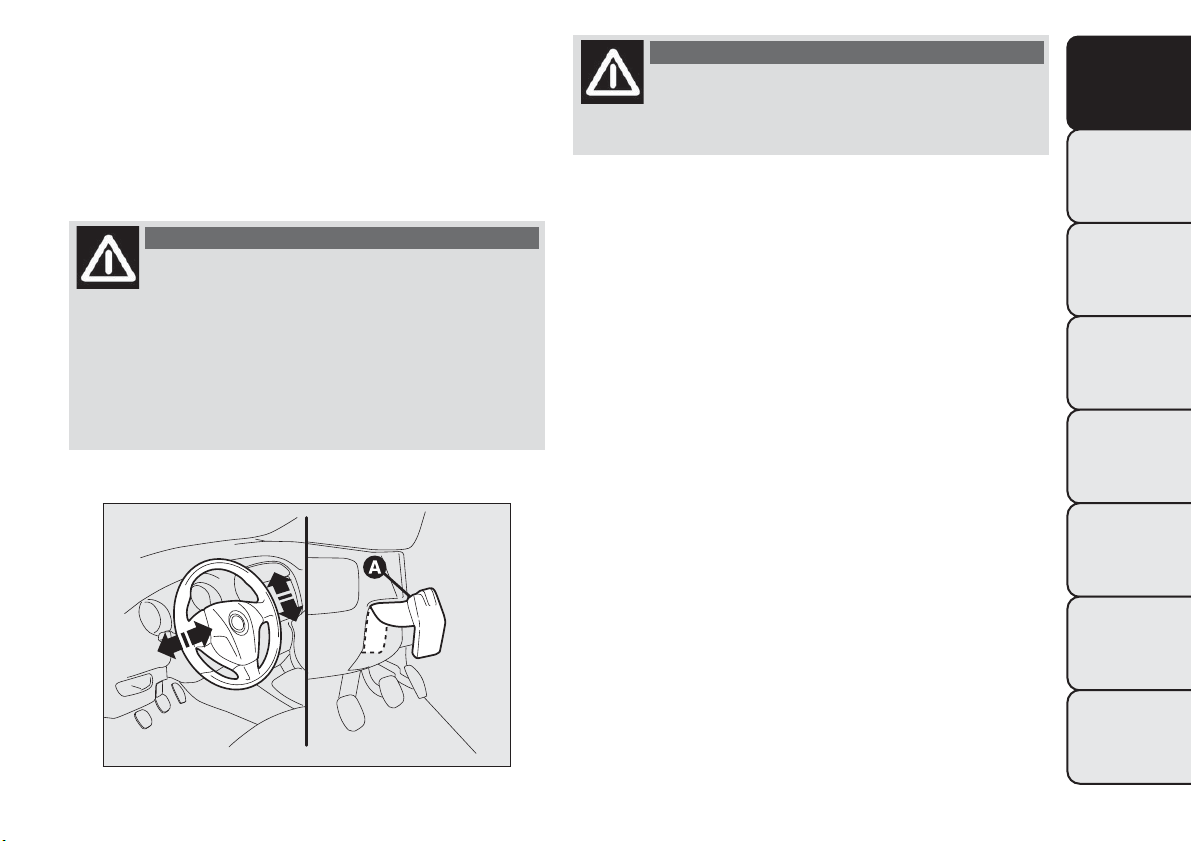
STEERING WHEEL
It can be adjusted both axially and vertically.
Release the lever A fig. 20 pulling it towards the
steering wheel, then adjust it in the most suitable
position and lock it pushing the lever A fully
forwards.
WARNING
It is absolutely forbidden to carry out
any aftermarket operation involving
steering system or steering column
modifications (e.g. installation of anti-theft
device) that could badly affect performance and
safety, invalidate the warranty and also result
in the car not meeting type-approval
requirements.
WARNING
All adjustments must be carried out only
with the vehicle stationary and engine
off.
fig. 20
F0Q0657
33
GETTING TO
KNOW YOUR CAR
SAFETY
STARTING AND
DRIVING
WARNING LIGHTS
AND MESSAGES
IN AN EMERGENCY
SERVICING AND
MAINTENANCE
TECHNICAL
SPECIFICATIONS
INDEX
REAR VIEW MIRRORS
INTERNAL MIRROR
The mirror is fitted with a safety device that causes
its release in the event of a violent impact with
the passenger.
Lever A fig. 21 can be used to move the mirror to
two different positions: normal or antiglare.
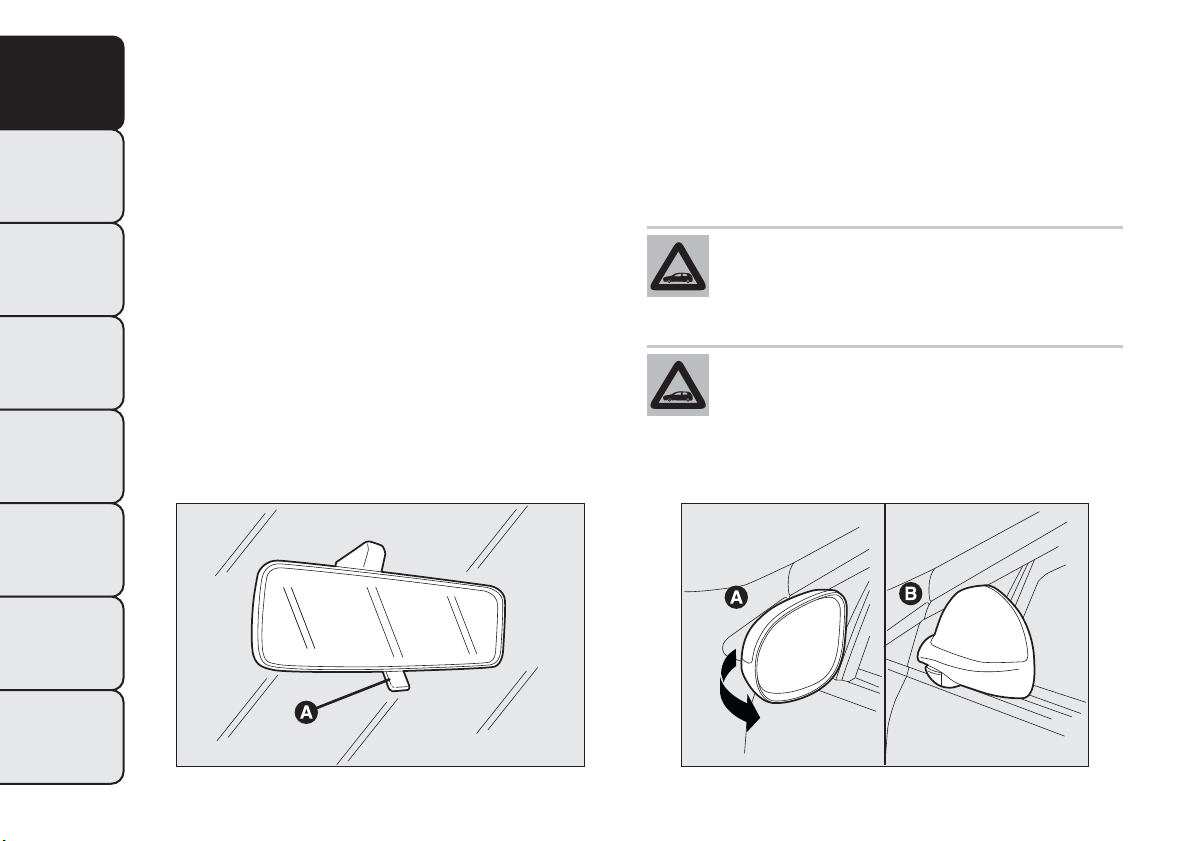
DOOR MIRRORS
Mirror manual folding
If necessary (for example when the mirror causes
difficulty in narrow spaces), it is possible to fold the
mirrors by moving them from position A fig. 22
to position B.
When driving, these mirrors must always
be in position A.
As the driver's door mirror is curved, it
may slightly alter the perception of
distance.
fig. 21
F0Q0659
fig. 22
F0Q0658
34
GETTING TO
KNOW YOUR CAR
SAFETY
STARTING AND
DRIVING
WARNING LIGHTS
AND MESSAGES
IN AN EMERGENCY
SERVICING AND
MAINTENANCE
TECHNICAL
SPECIFICATIONS
INDEX
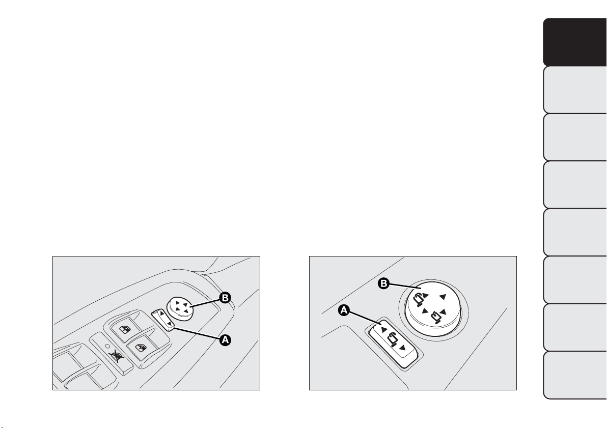
Electric adjustment
You can adjust the door mirrors only when the
ignition key is turned to MAR-ON.
Proceed as follows:
❒ use selector A fig. 23 to select the mirror (left or
right) to be adjusted;
❒ adjust the mirror using joystick B in the four
directions.
Mirror electric folding
(for versions/markets, where provided)
You can fold the door mirrors only when the ignition
key is turned to MAR-ON.
Proceed as follows:
❒ position selector A fig. 24 in neutral position (no
mirror selection);
❒ fold the mirror using joystick B in the side
directions fig. 24;
❒ press joystick B again to restore the mirrors to
driving position.
fig. 23
F0Q0623
fig. 24
F0Q0425
35
GETTING TO
KNOW YOUR CAR
SAFETY
STARTING AND
DRIVING
WARNING LIGHTS
AND MESSAGES
IN AN EMERGENCY
SERVICING AND
MAINTENANCE
TECHNICAL
SPECIFICATIONS
INDEX
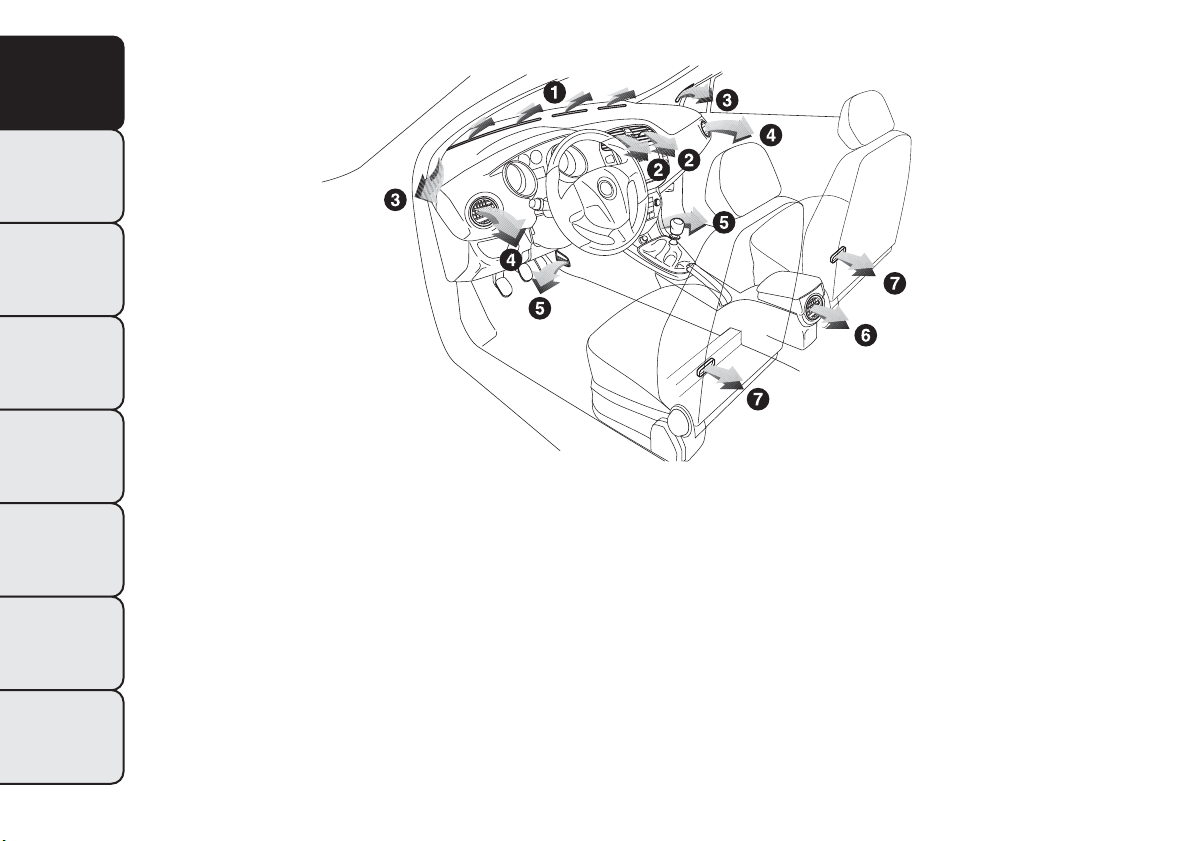
CLIMATE CONTROL/HEATING SYSTEM
1. Fixed upper diffuser for windscreen defrosting or demisting - 2. Adjustable central diffuser - 3. Fixed diffusers for side
window defrosting or demisting - 4. Adjustable and directable side diffusers - 5. Lower diffusers - 6. Directable and
adjustable rear vent - 7. Fixed rear diffusers for footwell.
fig. 25
F0Q0668
36
GETTING TO
KNOW YOUR CAR
SAFETY
STARTING AND
DRIVING
WARNING LIGHTS
AND MESSAGES
IN AN EMERGENCY
SERVICING AND
MAINTENANCE
TECHNICAL
SPECIFICATIONS
INDEX
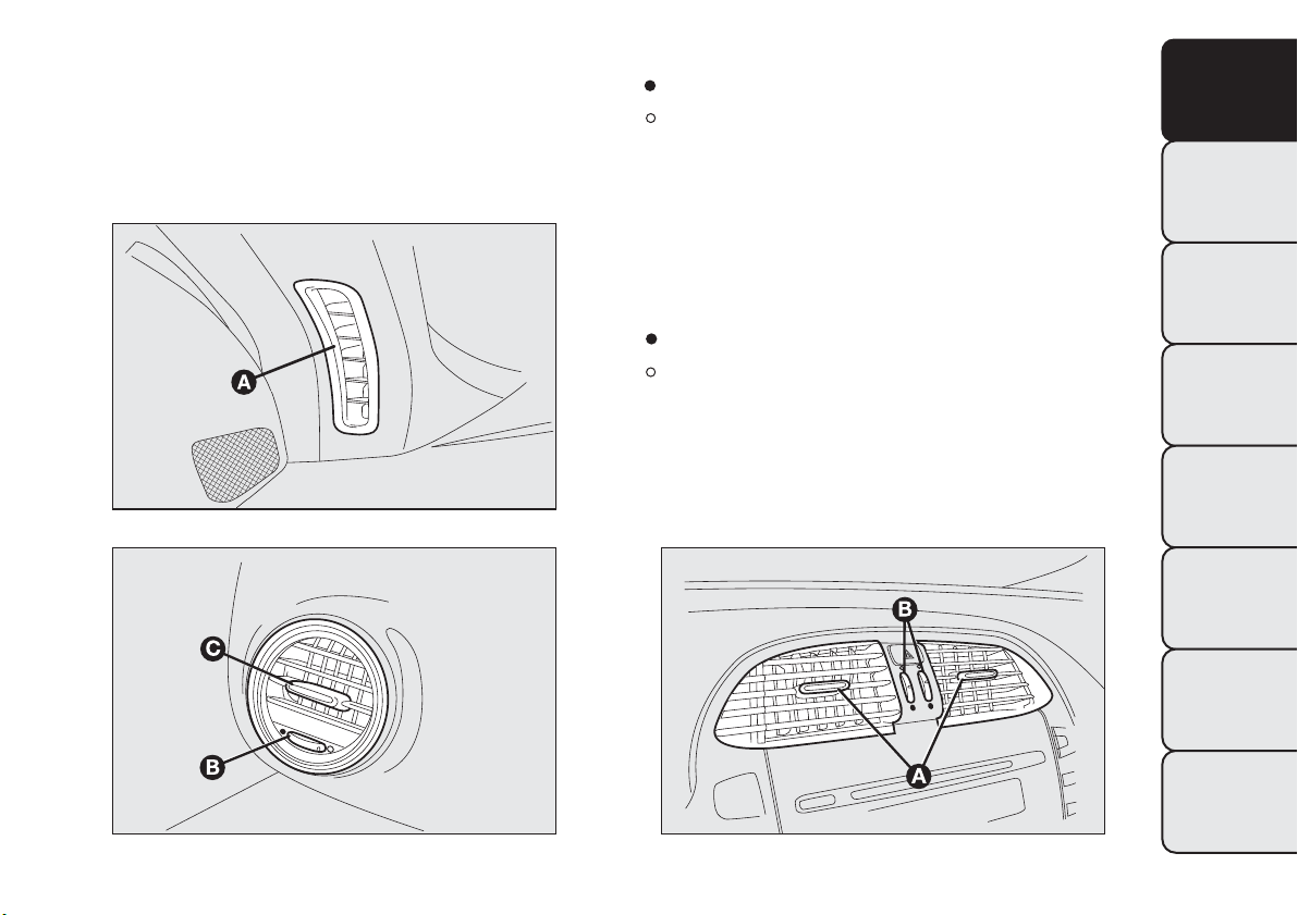
DIFFUSERS
ADJUSTABLE SIDE VENTS AND DIFFUSERS
A
Fixed diffuser for side window fig. 26.
B
Air flow adjustment control fig. 27:
= Fully closed
= Fully open.
C
Lateral and vertical air flow adjustment control.
fig. 27
CENTRAL DIFFUSERS
A
Lateral and vertical air flow adjustment controls
fig. 28.
B
Air flow adjustment controls fig. 28:
= Fully closed
= Fully open.
fig. 26
F0Q0626
fig. 27
F0Q0625
fig. 28
F0Q0627
37
GETTING TO
KNOW YOUR CAR
SAFETY
STARTING AND
DRIVING
WARNING LIGHTS
AND MESSAGES
IN AN EMERGENCY
SERVICING AND
MAINTENANCE
TECHNICAL
SPECIFICATIONS
INDEX
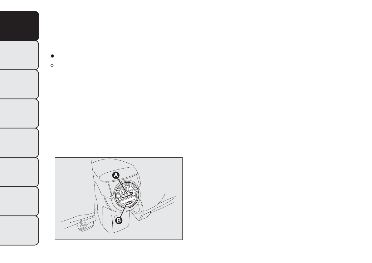
REAR DIFFUSER
(for versions/markets, where provided)
A
Lateral and vertical air flow adjustment controls
fig. 29.
B
Air flow adjustment control fig. 29:
= Fully closed
= Fully open.
On some versions, a storage compartment is fitted
instead of the rear diffuser.
fig. 29
F0Q0750
38
GETTING TO
KNOW YOUR CAR
SAFETY
STARTING AND
DRIVING
WARNING LIGHTS
AND MESSAGES
IN AN EMERGENCY
SERVICING AND
MAINTENANCE
TECHNICAL
SPECIFICATIONS
INDEX
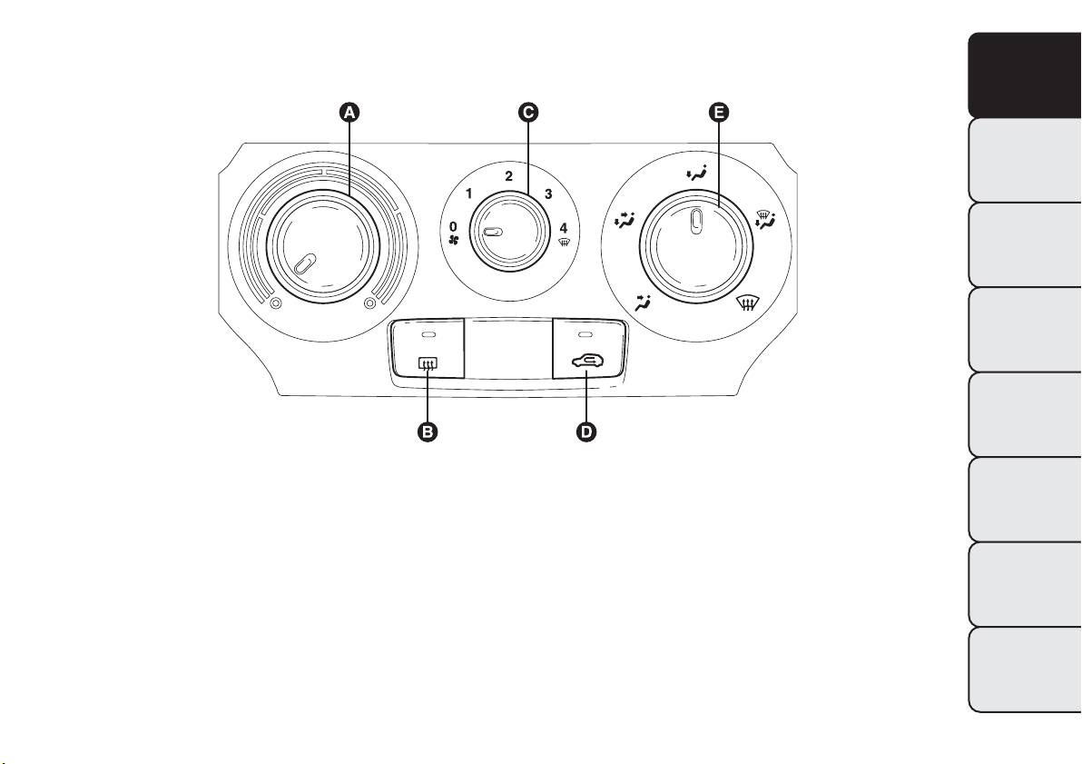
HEATING AND VENTILATION
CONTROLS
fig. 30
F0Q0609
39
GETTING TO
KNOW YOUR CAR
SAFETY
STARTING AND
DRIVING
WARNING LIGHTS
AND MESSAGES
IN AN EMERGENCY
SERVICING AND
MAINTENANCE
TECHNICAL
SPECIFICATIONS
INDEX

A
air temperature adjustment knob (hot/cold air
mixing)
B
heated rear window on/off button
C
fan activation knob
D
internal air recirculation on/off button
E
air distribution knob.
PASSENGER COMPARTMENT HEATING
Proceed as follows:
❒ turn knob A to the red section;
❒ turn knob C to the required speed;
❒ turn knob E to:
to warm the feet and demist the windscreen at
the same time
to warm the feet and keep the face cool (bi-level
function)
to warm the feet of those in the front and rear
seats
❒ to turn off internal air recirculation (LED on
button
off).
FAST FRONT WINDOW DEMISTING/
DEFROSTING
Proceed as follows:
❒ turn knob A fully to the right;
❒ turn knob C to
;
❒ turn knob E to
;
❒ turn off internal air recirculation (LED on button
off).
After demisting/defrosting, operate the controls to
maintain optimum visibility conditions.
Window demisting
In the event of considerable external moisture
and/or rain and/or large differences in temperature
inside and outside the passenger compartment,
perform the following preventive window demisting
procedure:
❒ to turn off internal air recirculation (LED on
button
off);
❒ turn knob A to the red section;
❒ turn knob C to the second speed level;
❒ turn knob E to
or to if there is no sign of
the windows steaming up.
HEATED REAR WINDOW AND DOOR
MIRRORS DEMISTING/DEFROSTING
Press button
to activate this function; when this
function is activated, the button LED
lights up.
This function is timed and will deactivate
automatically after 20 minutes. Press the button
again to switch the function off in advance.
IMPORTANT Do not apply stickers on the inside of
the rear window over the heating filaments to avoid
damage.
40
GETTING TO
KNOW YOUR CAR
SAFETY
STARTING AND
DRIVING
WARNING LIGHTS
AND MESSAGES
IN AN EMERGENCY
SERVICING AND
MAINTENANCE
TECHNICAL
SPECIFICATIONS
INDEX

FAN SPEED ADJUSTMENT
To ventilate the passenger compartment properly,
proceed as follows:
❒ fully open the central and side air diffusers;
❒ turn knob A to the blue section;
❒ turn knob C to the required speed;
❒ turn knob E to
;
❒ turn off internal air recirculation (LED on button
off).
INTERNAL AIR RECIRCULATION
ACTIVATION
Press button
: when the function is on, the
button LED lights up. It is advisable to switch the
internal air recirculation on while standing in queues
or in tunnels to prevent the introduction of polluted
air. However, it is better not to use the function
for long periods, particularly if there are many people
on board, to prevent the windows from misting.
IMPORTANT Internal air recirculation makes it
possible to reach the required heating or cooling
conditions more quickly depending on the mode
selected. Do not use the internal air recirculation
function on rainy/cold days as it would considerably
increase the possibility of the windows misting.
ADDITIONAL HEATER
(for versions/markets, where provided)
This device warms up the passenger compartment
more quickly when it is very cold and the engine
coolant temperature is low.
The additional heater comes on automatically when
the engine is started, if knob A is turned to the
last red sector and the fan (knob C) is at least at the
first speed level.
The heater switches off automatically when the
required comfort conditions are achieved.
IMPORTANT The heater will not turn on if the
battery voltage is too low.
41
GETTING TO
KNOW YOUR CAR
SAFETY
STARTING AND
DRIVING
WARNING LIGHTS
AND MESSAGES
IN AN EMERGENCY
SERVICING AND
MAINTENANCE
TECHNICAL
SPECIFICATIONS
INDEX
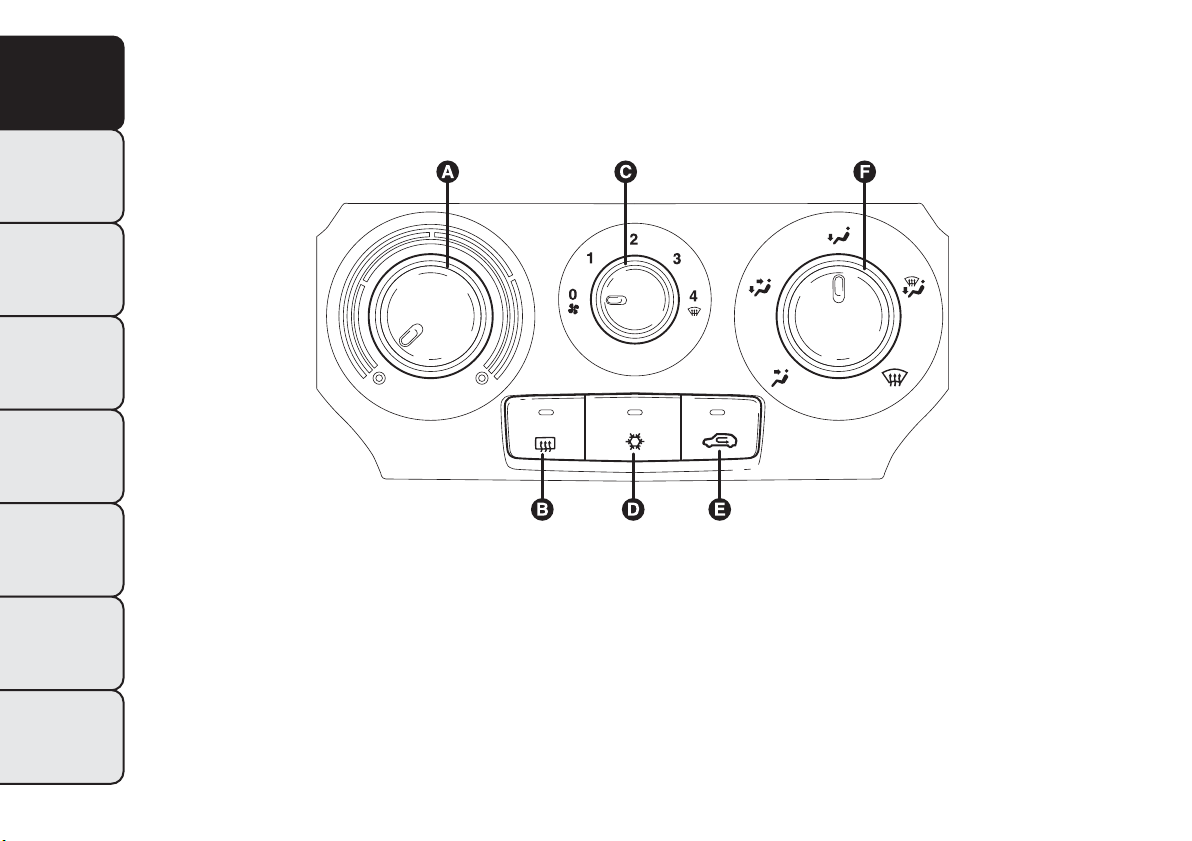
MANUAL CLIMATE CONTROL
SYSTEM
(for versions/markets, where provided)
CONTROLS
fig. 31
F0Q0610
42
GETTING TO
KNOW YOUR CAR
SAFETY
STARTING AND
DRIVING
WARNING LIGHTS
AND MESSAGES
IN AN EMERGENCY
SERVICING AND
MAINTENANCE
TECHNICAL
SPECIFICATIONS
INDEX

A
air temperature adjustment knob (hot/cold air
mixing)
B
heated rear window on/off button
C
fan activation knob
D
climate control system compressor on/off button
E
internal air recirculation on/off button
F
air distribution knob.
PASSENGER COMPARTMENT HEATING
Proceed as follows:
❒ turn knob A to the red section;
❒ turn knob C to the required speed;
❒ turn knob F to:
to warm the feet and demist the windscreen at
the same time
to warm the feet and keep the face cool (bi-level
function)
to warm the feet of those in the front and rear
seats
❒ to turn off internal air recirculation (LED on
button
off).
FAST FRONT WINDOW DEMISTING/
DEFROSTING
Proceed as follows:
❒ press the
button
❒ turn knob A fully to the right;
❒ turn knob C to
;
❒ turn knob E to
;
❒ turn off internal air recirculation (LED on button
off).
After demisting/defrosting, operate the controls to
maintain optimum visibility conditions.
Window demisting
In the event of considerable external moisture
and/or rain and/or large differences in temperature
inside and outside the passenger compartment,
perform the following preventive window demisting
procedure:
❒ press the
button
❒ turn off internal air recirculation (LED on button
off);
❒ turn knob A to the red section;
❒ turn knob C to the second speed level;
❒ turn knob F to
or to if there is no sign of
the windows steaming up.
The climate control system is very useful for
demisting the windows more quickly: just carry out
the above procedure and activate the system by
pressing button
.
43
GETTING TO
KNOW YOUR CAR
SAFETY
STARTING AND
DRIVING
WARNING LIGHTS
AND MESSAGES
IN AN EMERGENCY
SERVICING AND
MAINTENANCE
TECHNICAL
SPECIFICATIONS
INDEX
HEATED REAR WINDOW AND DOOR
MIRRORS DEMISTING/DEFROSTING
Press button
to activate this function: when this
function is activated, the button LED
lights up.
This function is timed and will deactivate
automatically after 20 minutes. Press the button
again to switch the function off in advance.
IMPORTANT Do not apply stickers on the inside of
the rear window over the heating filaments to avoid
damage.
FAN SPEED ADJUSTMENT
To ventilate the passenger compartment properly,
proceed as follows:
❒ fully open the central and side air diffusers;
❒ turn knob A to the blue section;
❒ turn knob C to the required speed;
❒ turn knob E to
;
❒ turn off internal air recirculation (LED on button
off).
INTERNAL AIR RECIRCULATION
ACTIVATION
Press button
: when the function is on, the
button LED lights up.
It is advisable to switch the internal air recirculation
on while standing in queues or in tunnels to prevent
the introduction of polluted air. However, it is better
not to use the function for long periods, particularly
if there are many people on board, to prevent the
windows from misting.
IMPORTANT Internal air recirculation makes it
possible to reach the required heating or cooling
conditions more quickly depending on the mode
selected. It is not advisable to switch the internal air
recirculation on when it is rainy/cold or the windows
might steam up, especially if the climate control
system is not turned on.
CLIMATE CONTROL SYSTEM (cooling)
Proceed as follows:
❒ turn knob A to the blue section;
❒ turn knob C to the required speed;
❒ turn knob F to
;
❒ press
and buttons (button LEDs on).
Cooling adjustment
Proceed as follows:
❒ deactivate the
button (LED on button off);
❒ turn knob A rightwards to increase the
temperature;
❒ turn knob C leftwards to reduce the fan speed.
44
GETTING TO
KNOW YOUR CAR
SAFETY
STARTING AND
DRIVING
WARNING LIGHTS
AND MESSAGES
IN AN EMERGENCY
SERVICING AND
MAINTENANCE
TECHNICAL
SPECIFICATIONS
INDEX

ADDITIONAL HEATER
(for versions/markets, where provided)
This device warms up the passenger compartment
more quickly when it is very cold and the engine
coolant temperature is low.
The additional heater comes on automatically when
the engine is started, if knob A is turned to the
last red sector and the fan (knob C) is at least at the
first speed level.
The heater switches off automatically when the
required comfort conditions are achieved.
IMPORTANT The heater will not turn on if the
battery voltage is too low.
SYSTEM MAINTENANCE
In winter, the climate control system must be turned
on at least once a month for about 10 minutes.
Before summer, have the system checked at a Fiat
Dealership.
45
GETTING TO
KNOW YOUR CAR
SAFETY
STARTING AND
DRIVING
WARNING LIGHTS
AND MESSAGES
IN AN EMERGENCY
SERVICING AND
MAINTENANCE
TECHNICAL
SPECIFICATIONS
INDEX
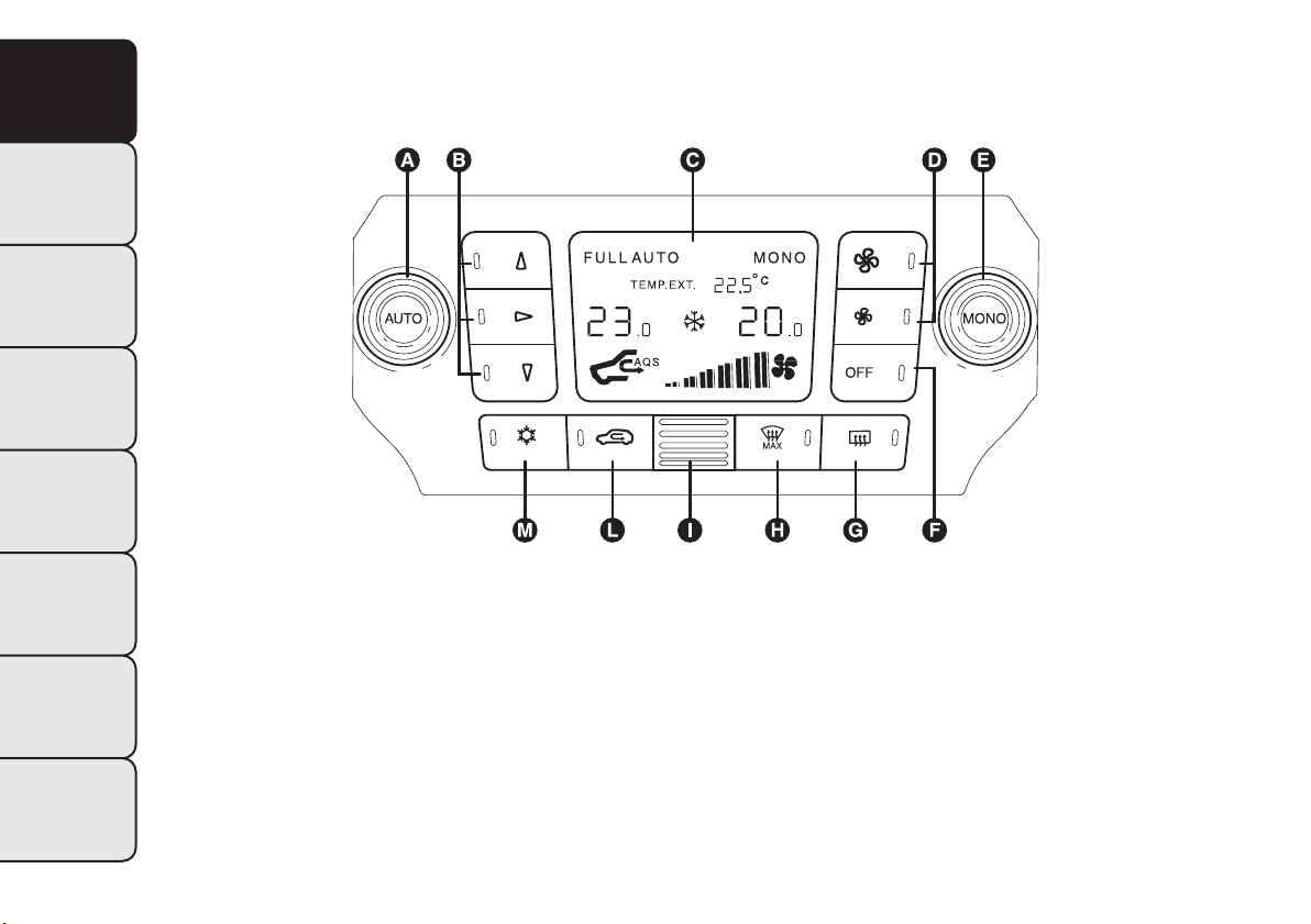
AUTOMATIC DUAL ZONE CLIMATE
CONTROL SYSTEM
(for versions/markets, where provided)
fig. 32
F0Q0611
46
GETTING TO
KNOW YOUR CAR
SAFETY
STARTING AND
DRIVING
WARNING LIGHTS
AND MESSAGES
IN AN EMERGENCY
SERVICING AND
MAINTENANCE
TECHNICAL
SPECIFICATIONS
INDEX

DESCRIPTION
The car is equipped with a dual zone climate control
system which allows you to adjust the air
temperature on the driver's and the passenger's side
separately.
The system has an AQS function (Air Quality
System), which automatically activates internal air
recirculation when the outside air is polluted (e.g. in
traffic queues and tunnels).
CONTROLS
A
AUTO function activation button (automatic
operation) and driver side temperature adjustment
knob
B
air distribution selection button
C
climate control system information display
D
fan speed increase/decrease
E
MONO function activation button (set
temperature alignment) and passenger side
temperature adjustment knob
F
climate control system on/off button
G
heated rear window on/off button
H
MAX-DEF function activation button (rapid
defrosting/demisting of front windows)
I
internal air temperature sensor
L
internal air recirculation and AQS function on/off
button
M
climate control system compressor on/off button
SWITCHING ON THE CLIMATE CONTROL
SYSTEM
The system can be activated by pressing any of the
buttons; it is, however, advisable to set the desired
temperatures on the
display, then press the AUTO button.
The climate control system allows you to customise
the temperatures requested (driver side and
passenger side) with a maximum difference of 7°C.
The climate control system compressor works
only with the engine running and an outside
temperature of above 4°C.
AUTOMATIC OPERATION OF THE
CLIMATE CONTROL SYSTEM (AUTO
function)
Press the AUTO button; the system will
automatically adjust:
❒ the amount of air introduced into the passenger
compartment;
❒ the distribution of the air in the passenger
compartment;
cancelling all previous manual adjustments.
During climate control system automatic operation,
the words FULL AUTO appear on the display.
47
GETTING TO
KNOW YOUR CAR
SAFETY
STARTING AND
DRIVING
WARNING LIGHTS
AND MESSAGES
IN AN EMERGENCY
SERVICING AND
MAINTENANCE
TECHNICAL
SPECIFICATIONS
INDEX
During automatic operation it is still possible to
adjust the temperatures set and carry out the
following operations manually:
❒ fan speed adjustment;
❒ air distribution selection;
❒ internal air recirculation and AQS function
activation/deactivation;
❒ climate control system compressor activation.
WARNING
It is advisable not to use the internal air
recirculation function when the outside
temperature is low, because the windows could
mist rapidly.
FAN SPEED ADJUSTMENT
Press button
to increase/decrease the fan speed.
The 12 possible speeds are indicated by bars lighting
up on the display:
❒ maximum fan speed = all bars lit
❒ minimum fan speed = one bar lit.
The fan can be disabled (no bars lit) only if the
climate control system compressor has been
switched off by pressing button
.
To restore automatic fan speed control after a
manual adjustment, press the AUTO button.
RAPID FRONT WINDOW
DEMISTING/DEFROSTING
(MAX-DEF function)
Press button to automatically activate the timed
operation of all the functions required to rapidly
demist/defrost the windscreen and front side
windows.
The functions are:
❒ climate control system compressor activation
(with an outside temperature of above 4°C);
❒ switching off, if previously on, of the internal air
recirculation (LED on button
off);
❒ activation of heated rear window (LED on button
on) and door mirror heater coils;
❒ setting maximum air temperature;
❒ activation of air flow.
HEATED REAR WINDOW AND DOOR
MIRRORS DEMISTING/DEFROSTING
Press button
to activate: when this function is
activated, the button LED switches on.
This function is timed and will deactivate
automatically after 20 minutes. Press the button
again to switch the function off in advance.
IMPORTANT Do not apply stickers on the inside of
the rear window over the heating filaments to avoid
damage.
48
GETTING TO
KNOW YOUR CAR
SAFETY
STARTING AND
DRIVING
WARNING LIGHTS
AND MESSAGES
IN AN EMERGENCY
SERVICING AND
MAINTENANCE
TECHNICAL
SPECIFICATIONS
INDEX

IMPORTANT Press to introduce air from the
outside (in this case the LED on the button should
be off).
ACTIVATION OF INTERNAL AIR
RECIRCULATION AND ENABLEMENT OF
AQS FUNCTION (Air Quality System)
Press button
. Internal air recirculation is carried
out according to three possible operating modes:
❒ automatic control, signalled by the AQS sign
on the display and the LED on button
being
off;
❒ forced deactivation (internal air recirculation
always off with introduction of outside air),
indicated by the LED on button
being off;
❒ forced activation (internal air recirculation always
on), signalled by the LED on button
being lit.
When OFF button is pressed, the climate control
system automatically activates internal air
recirculation (the LED on button T should be on). It
is still possible to activate outside air recirculation
(LED on the button off) and vice versa, by pressing
button T.
With the OFF button pressed (LED on the button is
lit up), it is not possible to enable the AQS (Air
Quality System) function.
IMPORTANT Internal air recirculation makes it
possible to reach the required heating or cooling
conditions more quickly depending on the mode
selected. It is not advisable to switch the internal air
recirculation on when it is rainy/cold to prevent
the windows from misting, especially if the climate
control system has not been activated. It is advisable
to switch the internal air recirculation on whilst
queuing or in tunnels to prevent the introduction of
polluted air. Do not use the function for a long
time, particularly if there are several passengers on
board, to prevent the windows from misting.
AQS (Air Quality System) function activation
The AQS function (AQS sign on the display)
automatically activates internal air recirculation when
the outside air is polluted (e.g. in traffic queues and
tunnels).
IMPORTANT With the AQS function active, after
approx. 15 consecutive minutes of the internal
air recirculation system functioning, the climate
control system enables the intake of outside air for
approximately 1 minute to freshen the air in the
passenger compartment. This takes place regardless
of the pollution level of the outside air.
49
GETTING TO
KNOW YOUR CAR
SAFETY
STARTING AND
DRIVING
WARNING LIGHTS
AND MESSAGES
IN AN EMERGENCY
SERVICING AND
MAINTENANCE
TECHNICAL
SPECIFICATIONS
INDEX
SET TEMPERATURE ALIGNMENT
(MONO function)
Press the MONO button to align the temperature
between the driver side and passenger side.
Then turn the AUTO or MONO knob to
increase/decrease the temperature between the two
areas by the same amount.
Press MONO again to deactivate the function.
CLIMATE CONTROL SYSTEM
COMPRESSOR ACTIVATION/
DEACTIVATION
Press the
button to switch on the climate control
system compressor.
Compressor engagement
❒ button LED
on;
❒
symbol appears on display.
Compressor deactivation
❒ button LED
off;
❒
symbol on display disappears;
❒ internal air recirculation excluded;
❒ AQS function disabled.
With the climate control system compressor
switched off, air cannot be introduced into the
passenger compartment that has a lower
temperature than the outside air; in this case the
symbol in the display will flash.
The deactivation of the climate control system
compressor is memorised even after the engine has
stopped. To reactivate the climate control system
compressor, press the
or AUTO button again:
if you press AUTO, the other manual settings will be
cancelled.
IMPORTANT In order to preserve the battery
charge, the electronic climate control management
permits a higher ventilation speed than minimum
only if the engine is running at a speed greater than
750 rpm. When the speed drops below this
threshold – possible when setting off, for example –
the ventilation speed is automatically reduced to
minimum.
AIR DISTRIBUTION SELECTION
Press one or more of these buttons
/ / to
manually select one of the seven possible air
distribution settings for the passenger compartment:
Air flow to the windscreen and front side
window diffusers to demist/defrost them.
Air flow to the front and rear footwell diffusers.
This air distribution allows the passenger
compartment to be warmed up quickly.
Air flow distribution between front and
rear diffusers, centre/side dashboard
diffusers, rear diffuser and windscreen and
front side window demisting/defrosting
diffusers.
Air flow distribution to centre/side dashboard
diffusers (passenger's body).
50
GETTING TO
KNOW YOUR CAR
SAFETY
STARTING AND
DRIVING
WARNING LIGHTS
AND MESSAGES
IN AN EMERGENCY
SERVICING AND
MAINTENANCE
TECHNICAL
SPECIFICATIONS
INDEX

Air flow distribution between footwell
diffusers and windscreen and front side
window defrosting/demisting diffusers. This
distribution setting allows the passenger
compartment to be warmed effectively and
prevents the windows from misting.
Air flow distribution between footwell
diffusers (hotter air) and centre/side
dashboard diffusers and rear diffuser (cooler
air).
Air flow distribution between centre/side
dashboard diffusers, rear diffuser and
windscreen and front side window
demisting/defrosting diffusers. This
distribution setting ventilates the passenger
compartment well and prevents the windows
from misting up.
IMPORTANT For the climate control system to
function, at least one of the buttons
/ / must
be operated. The system does not allow the
deactivation of all the buttons
/ / .
IMPORTANT Push the OFF button to turn the
climate control system back on: in this way, all
operating conditions memorised before switching off
are restored.
To restore automatic control of the air distribution
after a manual selection, press the AUTO button.
ADDITIONAL HEATER
(for versions/markets, where provided)
This device warms up the passenger compartment
more quickly when it is very cold and the engine
coolant temperature is low.
In these conditions, the device comes on
automatically when the engine is started and the fan
is on.
The heater switches off automatically when the
required comfort conditions are achieved.
IMPORTANT The heater will not turn on if the
battery voltage is too low.
SWITCHING OFF THE CLIMATE CONTROL
SYSTEM
Press the OFF button.
The following information is shown on the display:
❒ OFF;
❒ outside temperature indication;
❒ internal air recirculation on indication (LED on
button
lit).
51
GETTING TO
KNOW YOUR CAR
SAFETY
STARTING AND
DRIVING
WARNING LIGHTS
AND MESSAGES
IN AN EMERGENCY
SERVICING AND
MAINTENANCE
TECHNICAL
SPECIFICATIONS
INDEX

EXTERIOR LIGHTS
The left lever fig. 33 includes the controls for the
exterior lights.
The exterior lights can only be switched on when
the ignition key is at MAR-ON.
LIGHTS OFF
Ring nut turned to position
.
SIDE LIGHTS
Turn the ring nut to position
.
The warning light
switches on in the instrument
panel.
DIPPED HEADLIGHTS
Turn the ring nut to position
.
The warning light
switches on in the instrument
panel.
MAIN BEAM HEADLIGHTS
With the ring nut at
position, push the stalk
forward towards the dashboard (stable position).
The warning light
switches on in the instrument
panel.
To turn the main beam headlights off, pull the stalk
towards the steering wheel (dipped headlights will
turn on).
PARKING LIGHTS
These lights can be turned on only with the ignition
key at STOP or extracted by turning the ring nut
on the left stalk first to position
and then to
position
or .
The warning light
switches on in the instrument
panel. Operate the direction indicator stalk to select
the side (right or left).
FLASHING
Pull the stalk towards the steering wheel (unstable
position) regardless of the position of the ring nut.
The warning light
switches on in the instrument
panel.
fig. 33
F0Q0649
52
GETTING TO
KNOW YOUR CAR
SAFETY
STARTING AND
DRIVING
WARNING LIGHTS
AND MESSAGES
IN AN EMERGENCY
SERVICING AND
MAINTENANCE
TECHNICAL
SPECIFICATIONS
INDEX
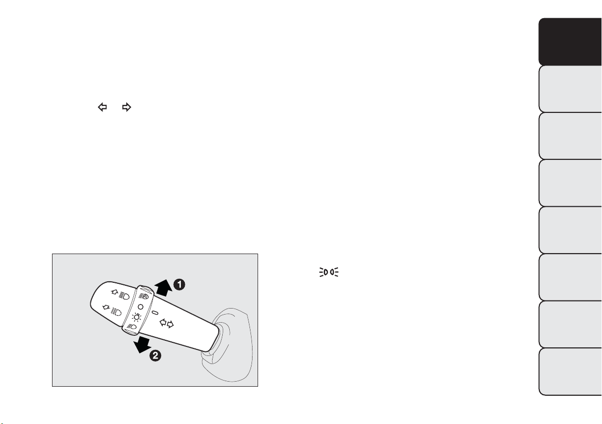
DIRECTION INDICATORS
Place the stalk in the (stable) position fig. 34:
❒ up (position 1): activates the right direction
indicator
❒ down (position 2): activates the left direction
indicator
Warning light
or will flash in the instrument
panel.
Direction indicators are switched off automatically
when the steering wheel is straightened.
Lane change function
If you wish to signal a lane change, put the left stalk
in the unstable position for less than half a second.
The direction indicator on the side selected will flash
five times and then switch off automatically.
“Cornering lights”
When the dipped headlights are on and the speed is
below 40 km/h, if the steering wheel rotation angle is
large or the direction indicators are on, a light
(incorporated in the fog light) will come on on the
relevant side to improve visibility at nighttime.
"FOLLOW ME HOME" DEVICE
This allows the space in front of the car to be lit up
for a certain period of time.
Activation
With the ignition key turned to STOP or removed,
pull the stalk fig. 35 towards the steering wheel
within 2 minutes from when the engine is turned off.
At each single movement of the stalk, the lights
will remain on for an extra 30 seconds up to a
maximum of 210 seconds; then the lights are
switched off automatically.
Each action of the stalk corresponds with the lighting
of the
warning light in the instrument panel
(along with a message shown on the display) (see
"Warning lights and messages" chapter).
Deactivation
Keep the stalk pulled towards the steering wheel for
more than 2 seconds.
fig. 34
F0Q0650
53
GETTING TO
KNOW YOUR CAR
SAFETY
STARTING AND
DRIVING
WARNING LIGHTS
AND MESSAGES
IN AN EMERGENCY
SERVICING AND
MAINTENANCE
TECHNICAL
SPECIFICATIONS
INDEX
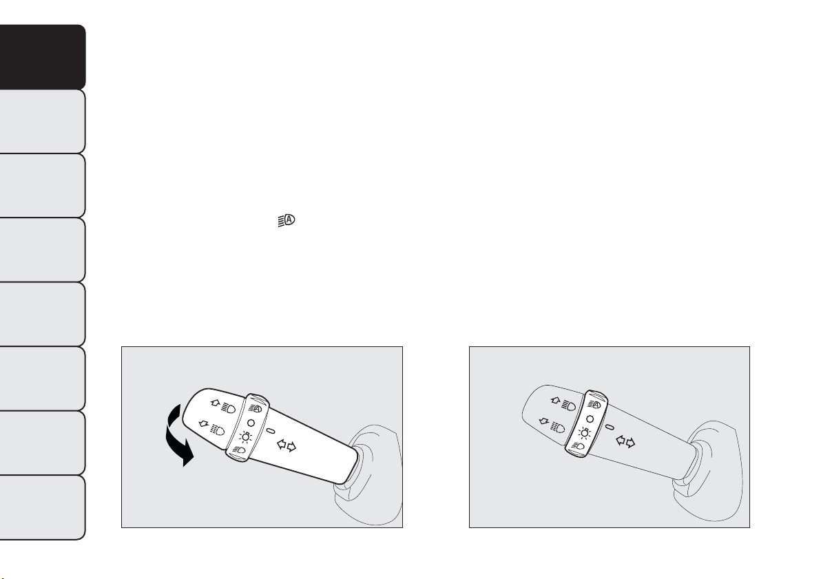
AUTOMATIC HEADLIGHT SENSOR
(dusk sensor)
(for versions/markets, where provided)
It detects variations in brightness outside the vehicle
depending on the light sensitivity setting: the greater
the sensitivity, the less outside light needed to
activate the exterior lights being turned on.
The sensitivity of the dusk sensor may be adjusted by
means of the "Setup menu" on the instrument panel.
Activation
Turn the ring nut to position
fig. 36: this turns the
side lights and the dipped headlights on
simultaneously and automatically depending on the
exterior brightness conditions.
The headlights can only be flashed with the sensor
on.
Deactivation
The dipped headlights will switch off followed after
approximately 10 seconds by the side lights, when
the sensor is deactivated.
The sensor is not capable of detecting the presence
of fog therefore, in these circumstances, the lights
have to be turned on manually.
fig. 35
F0Q0651
fig. 36
F0Q0652
54
GETTING TO
KNOW YOUR CAR
SAFETY
STARTING AND
DRIVING
WARNING LIGHTS
AND MESSAGES
IN AN EMERGENCY
SERVICING AND
MAINTENANCE
TECHNICAL
SPECIFICATIONS
INDEX
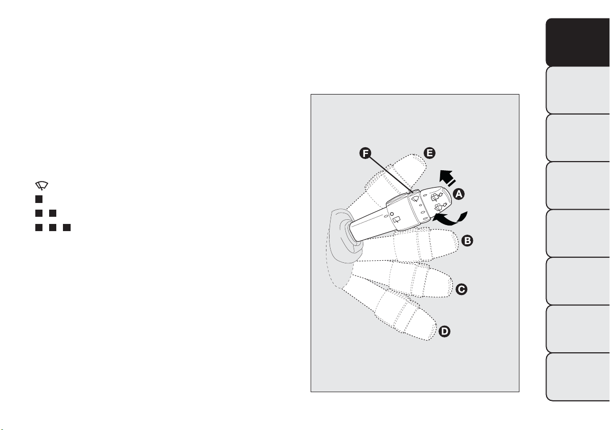
WINDOW CLEANING
WINDSCREEN WASHER/WIPER
They can be operated only with the ignition key
turned to MAR-ON.
The right stalk can be moved to five different
positions fig. 37:
A
windscreen wiper off.
B
intermittent operation.
With the stalk in position B, turn ring nut F to select
one of four different speeds for the intermittent
operation mode:
= intermittent low speed
= slow intermittent operation.
= medium intermittent operation.
= fast intermittent operation.
C
continuous slow operation;
D
continuous fast operation;
E
temporary fast operation (unstable position).
Temporary fast operation position E is limited to the
time that the stalk is manually held in this position.
The stalk returns to position A when it is released,
automatically stopping the windscreen wipers.
IMPORTANT With the windscreen wipers in use, if
reverse gear is engaged, the rear window wiper is
automatically activated.
fig. 37
F0Q0645
55
GETTING TO
KNOW YOUR CAR
SAFETY
STARTING AND
DRIVING
WARNING LIGHTS
AND MESSAGES
IN AN EMERGENCY
SERVICING AND
MAINTENANCE
TECHNICAL
SPECIFICATIONS
INDEX
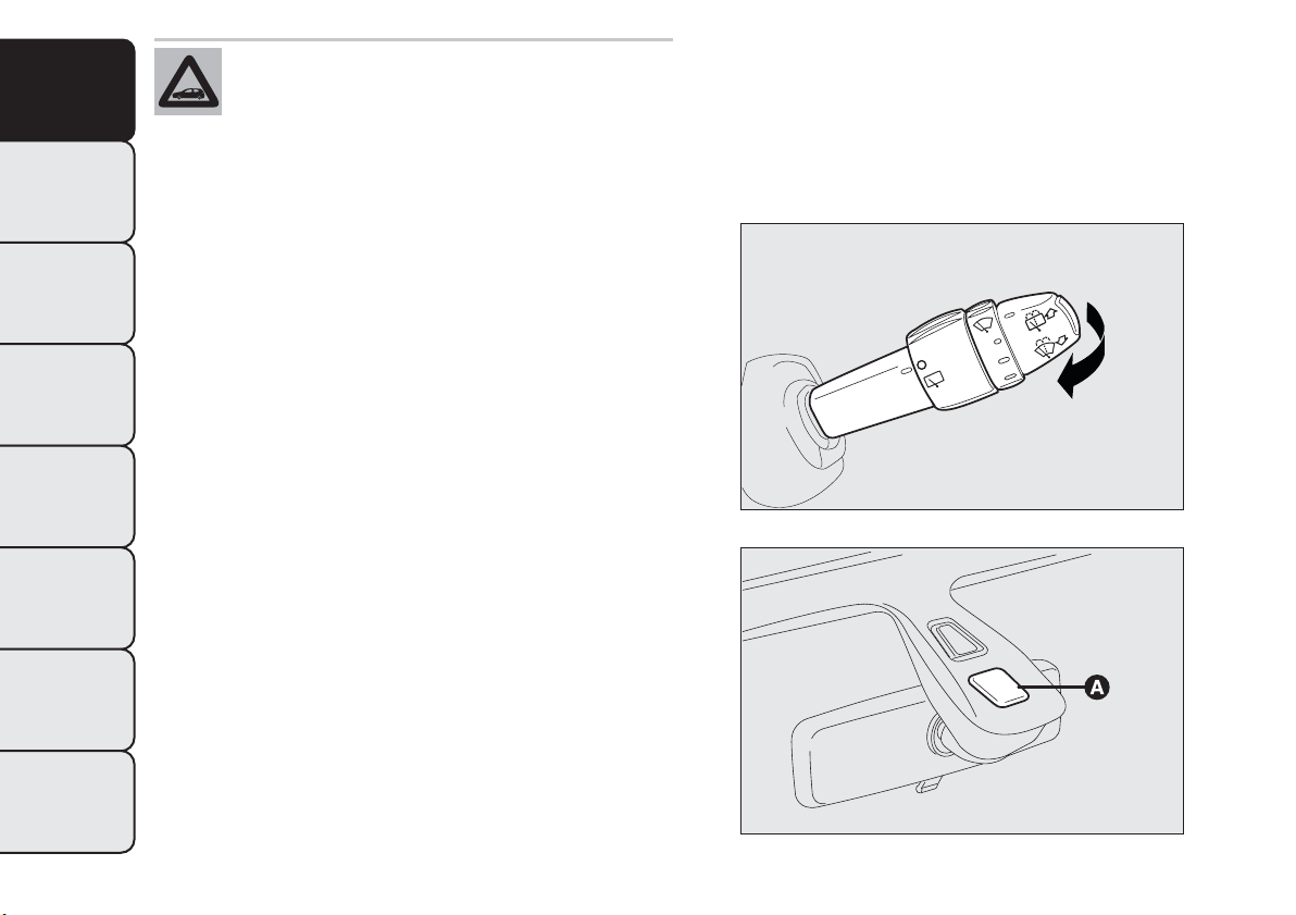
Never use the windscreen wipers to
remove layers of snow or ice from the
windscreen. In such conditions, the
windscreen wipers may be subjected to excessive
stress and the motor protection, which prevents
operation for a few seconds, may intervene. If
operation is not restored, contact a Fiat
Dealership.
"Smart washing" functionfig. 38
Pull the stalk towards the steering wheel (unstable
position) to operate the windscreen washer.
Keep the stalk pulled, with just one movement, to
operate the washer jet and the windscreen wiper;
the latter automatically turns on if you keep the stalk
pulled for more than half a second.
The windscreen wiper stops operating a few strokes
after releasing the stalk; a further “cleaning stroke”,
after a few seconds, completes the wiping operation.
RAIN SENSOR
(for versions/markets, where provided)
The rain sensor A fig. 39 is located behind the
interior rear view mirror in contact with the
windscreen and has the purpose of automatically
adjusting the frequency of the windscreen wiper
strokes depending on the intensity of the rain during
intermittent operation.
The sensor has an adjustment range that varies
progressively from wiper still (no stroke) when the
windscreen is dry, to wiper at first continuous speed
(slow continuous operation) with intense rain.
fig. 38
F0Q0646
fig. 39
F0Q0014
56
GETTING TO
KNOW YOUR CAR
SAFETY
STARTING AND
DRIVING
WARNING LIGHTS
AND MESSAGES
IN AN EMERGENCY
SERVICING AND
MAINTENANCE
TECHNICAL
SPECIFICATIONS
INDEX
Activation
Move the right stalk down by one click.
The activation of the sensor is signalled by a "stroke"
to show that the command has been acquired.
IMPORTANT Keep the glass in the sensor area clean.
By turning ring nut F fig. 37 is it possible to increase
the sensitivity of the rain sensor to obtain a more
rapid variation between wiper still (no stroke) when
the windscreen is dry, to wiper at first continuous
speed (slow continuous operation).
The increasing of the rain sensor sensitivity is also
signalled by a stroke of the wipers.
If the windscreen washer is used with the rain sensor
activated, the normal washing cycle is performed,
after which the rain sensor resumes its normal
automatic operation.
Deactivation
Turn the ignition key to STOP.
At the next start-up (key at MAR-ON), the sensor
will not be reactivated even if the stalk is at B fig. 37.
To activate the sensor, move the stalk to position
A or C and then back to position B.
Rain sensor activation will be indicated by at least
one wiper “stroke” even if the windscreen is dry.
Do not activate the rain sensor when
washing the car in an automatic car wash.
Make sure the device is switched off if
there is ice on the windscreen.
WARNING
Make sure the device is switched off
whenever the windscreen is being
cleaned.
REAR WINDOW WASHER/WIPER
It can be operated only with the ignition key turned
to MAR-ON. The function stops when the stalk is
released.
Turning the stalk ring nut A fig. 40 from position
to position will operate the rear window wiper
as follows:
❒ in intermittent mode when the rear window wiper
is not operating;
❒ in synchronous mode (at half the speed of the
windscreen wiper) when the windscreen wiper
is operating;
❒ in continuous mode with reverse gear engaged and
the control active.
With the windscreen wiper on and reverse gear
engaged the rear window wiper is activated in
continuous mode. Pushing the stalk towards the
dashboard (unstable position) will activate the rear
window washer jet.
57
GETTING TO
KNOW YOUR CAR
SAFETY
STARTING AND
DRIVING
WARNING LIGHTS
AND MESSAGES
IN AN EMERGENCY
SERVICING AND
MAINTENANCE
TECHNICAL
SPECIFICATIONS
INDEX
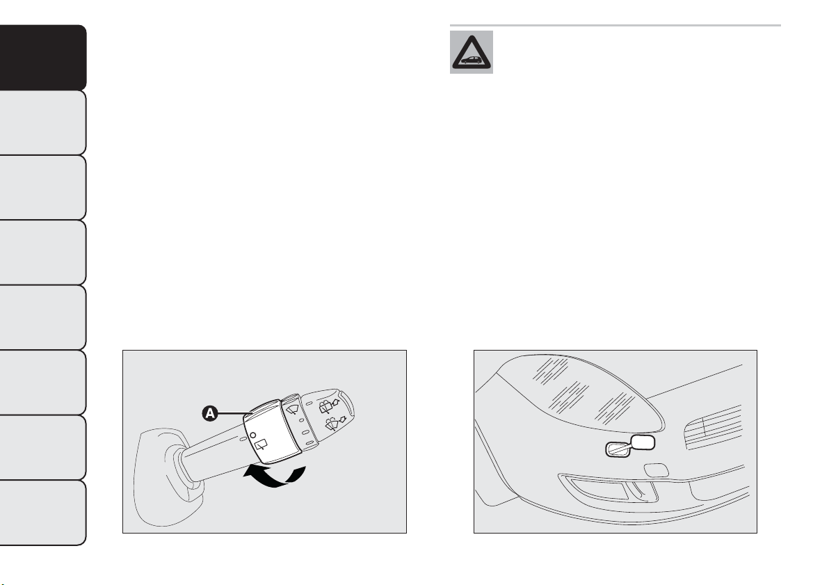
Keep the stalk pushed for more than half a second to
activate the rear window wiper as well. Releasing
the stalk will activate the smart washing function, as
described for the windscreen wiper.
HEADLIGHT WASHERS
(for versions/markets, where provided)
The headlight washers fig. 41 are retractable, i.e. they
are located inside the front bumper and work when
the windscreen washer is activated with the dipped
and/or main beam headlights on.
IMPORTANT Check the correct operation and
cleanliness of nozzles at regular intervals.
Do not use the rear window wiper to
removelayersofsnoworice.In
such conditions, the wiper may be
subjected to excessive stress and the motor
protection, which prevents operation for a few
seconds, may intervene. If operation is not
restored, contact a Fiat Dealership.
fig. 40
F0Q0653
fig. 41
F0Q0018
58
GETTING TO
KNOW YOUR CAR
SAFETY
STARTING AND
DRIVING
WARNING LIGHTS
AND MESSAGES
IN AN EMERGENCY
SERVICING AND
MAINTENANCE
TECHNICAL
SPECIFICATIONS
INDEX
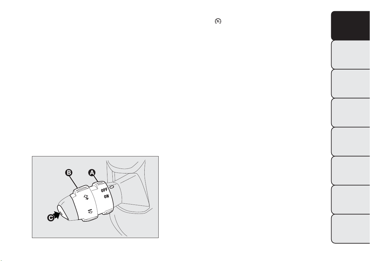
CRUISE CONTROL
(constant speed regulator)
(for versions/markets, where provided)
This is an electronically controlled driving assistance
device which allows the car to be driven at a chosen
speed above 30 km/h on long stretches of dry,
straight roads with few variations (e.g. motorways),
without having to depress the accelerator pedal.
The use of this device on extra-urban roads with
traffic is not therefore recommended. Do not use
the device in town.
TURNING THE DEVICE ON
Turn the ring nut A fig. 42 to the ON position.
The device must only be switched on in 4th gear or
higher. When travelling downhill with the device
engaged, the vehicle speed may slightly exceed the
preset one.
The activation is indicated by the turning on of
warning light
on the instrument panel (together
with the dedicated message on the display) (see
“Warning lights and messages” chapter).
STORING THEVEHICLE SPEED
Proceed as follows:
❒ turn ring nut A fig. 42 to ON and press the
accelerator pedal so that the car reaches the
desired speed;
❒ turn the ring nut B to (+) for at least three
seconds, then release it. The vehicle speed is now
memorised and you can therefore release the
accelerator pedal.
If needed (when overtaking for instance), you can
accelerate simply by depressing the accelerator pedal;
when you release the pedal, the vehicle goes back
to the speed set previously.
RESTORING STORED SPEED
If the device has been switched off, for example by
depressing the brake or clutch pedal, the memorised
speed can be restored as follows:
❒ accelerate progressively until a speed close to that
stored is reached;
❒ engage the gear selected at the time that the
speed was memorised (4th, 5th or 6th gear);
❒ press button C fig. 42.
fig. 42
F0Q0648
59
GETTING TO
KNOW YOUR CAR
SAFETY
STARTING AND
DRIVING
WARNING LIGHTS
AND MESSAGES
IN AN EMERGENCY
SERVICING AND
MAINTENANCE
TECHNICAL
SPECIFICATIONS
INDEX
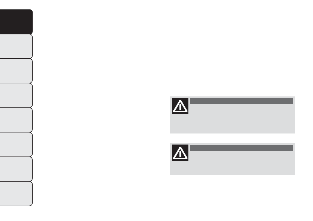
INCREASING THE STORED SPEED
This can be done in two ways:
❒ by pressing the accelerator and memorising the
new speed reached;
or
❒ by temporarily turning ring nut B fig. 42 to (+).
Each movement of the ring nut will correspond to a
slight increase in speed (about 1 km/h), while keeping
the ring nut turned will correspond to a continuous
speed increase.
REDUCING THE STORED SPEED
This can be done in two ways:
❒ by switching off the device and then memorising
the new speed;
or
❒ by keeping ring nut B fig. 42 turned to (–) until the
new speed is reached; it will then be memorised
automatically.
Each movement of the ring nut will correspond to a
slight reduction in speed (about 1 km/h), while
keeping the ring nut turned will correspond to a
continuous reduction in speed.
TURNING THE DEVICE OFF
Turn the ring nut A fig. 42 to OFF or turn the
ignition key to STOP. The device is automatically
turned off in one of the following cases:
❒ when the brake or clutch pedal is pressed;
❒ if the ASR or ESP system cuts in (for versions/
markets, where provided);
❒ if the gear is shifted in versions with Dualogic
gearbox (for versions/markets, where provided) in
Manual mode;
❒ if the Dualogic gearbox lever (where provided) is
inadvertently shifted to N or R.
WARNING
Whilst driving with the device on, never
place the gear lever in neutral and do
not move the Dualogic gearbox lever into
position N or R.
WARNING
If the device is faulty, turn ring nut A
fig. 42 to OFF, check the condition of the
protective fuse and contact a Fiat Dealership.
60
GETTING TO
KNOW YOUR CAR
SAFETY
STARTING AND
DRIVING
WARNING LIGHTS
AND MESSAGES
IN AN EMERGENCY
SERVICING AND
MAINTENANCE
TECHNICAL
SPECIFICATIONS
INDEX

ROOF LIGHTS
FRONT ROOF LIGHT WITH SPOT LIGHTS
Switch A fig. 43 switches the roof lights on/off.
With the switch A in the central position, the lights
C and D come on/go off when front doors are
opened/closed.
With switch A pressed to the left, lights C and D are
always off. With switch A pressed to the right, the
lights C and D are always on.
Lights switch on/off progressively.
Switch B controls the spot light function; when the
roof light is off, it switches on individually:
❒ light C if pressed on the left side;
❒ light D if pressed on the right side.
IMPORTANT Before getting out of the car, make
sure that both switches are in the central position:
when the doors are closed the lights will switch
off to avoid draining the battery. In any case, if the
switch is left in on position, the roof light switches
off automatically 15 minutes after the engine
switching off.
Roof light timing
To make getting in and out the vehicle easier,
especially at nighttime or in poorly lit areas, two
timing logics are available.
Timing when getting into the car
The roof lights switch on according to the following
modes:
❒ for around 10 seconds when the front doors are
unlocked;
❒ for about 3 minutes when one of the side doors is
opened;
❒ for about 10 seconds when the doors are closed.
The timing is interrupted when the ignition key is
turned to MAR-ON.
fig. 43
F0Q0669
61
GETTING TO
KNOW YOUR CAR
SAFETY
STARTING AND
DRIVING
WARNING LIGHTS
AND MESSAGES
IN AN EMERGENCY
SERVICING AND
MAINTENANCE
TECHNICAL
SPECIFICATIONS
INDEX
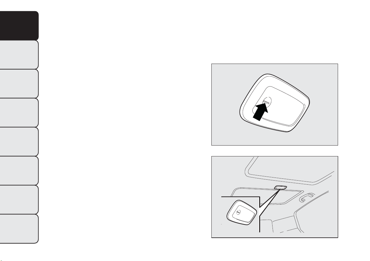
Timing when getting out of the car
After removing the key from the ignition switch, the
roof lights switch on as follows:
❒ within 2 minutes of the engine being switched off
for a period of around 10 seconds;
❒ when one of the side doors is opened for a period
of around 3 minutes;
❒ when one of the doors is closed for a period of
about 10 seconds.
❒ if the fuel cut-off switch operates, they are on for
about 15 minutes, then they switch off
automatically.
Door locking switches the lights off immediately
(unless the fuel cut-off switch is operating).
REAR ROOF LIGHT
Versions without sun rooffig. 44
In these versions, there are two rear roof lights.
Press the point indicated by the arrow to switch the
lights on/off (+ sign on the roof light lens cover).
The rear roof lights also come on in conjunction
with events that cause the front roof light to come
on.
Versions with sun rooffig. 45
In these versions, there is only one rear roof light.
Press the point indicated by the arrow to switch the
lights on/off (+ sign on the roof light lens cover).
The rear roof light also switches on in conjunction
with events that cause the front roof light to switch
on.
fig. 44
F0Q0670
fig. 45
F0Q0740
62
GETTING TO
KNOW YOUR CAR
SAFETY
STARTING AND
DRIVING
WARNING LIGHTS
AND MESSAGES
IN AN EMERGENCY
SERVICING AND
MAINTENANCE
TECHNICAL
SPECIFICATIONS
INDEX
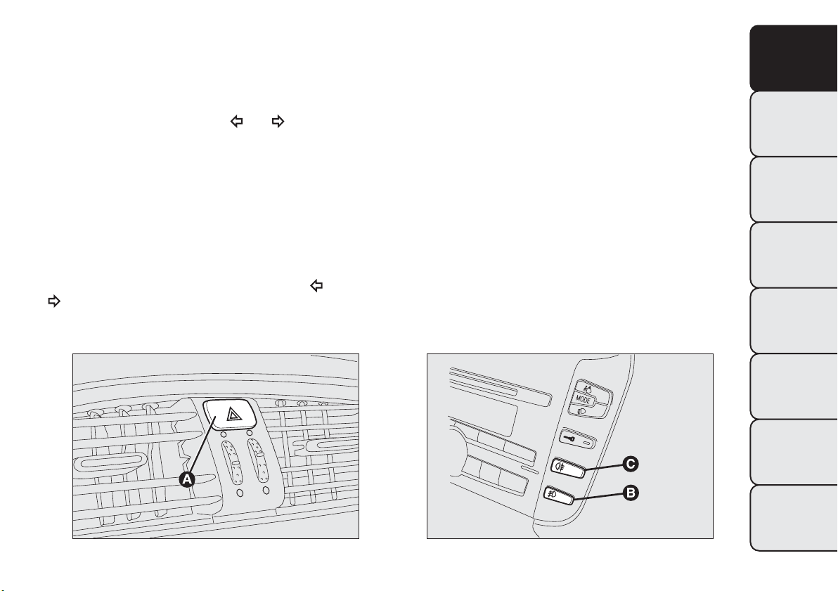
CONTROLS
HAZARD WARNING LIGHTS
They are turned on by pressing switch A fig. 46,
regardless of the position of the ignition key. With
the device on, warning lights
and light up in the
instrument panel.
Press button A again to switch the lights off.
IMPORTANT The use of hazard warning lights is
governed by the highway code of the country you are
in. Comply with legal requirements.
Emergency braking
During emergency braking, the hazard warning lights
come on automatically and warning lights
and
on the panel also come on.
The function switches off automatically when
emergency braking ceases.
FOG LIGHTS
(for versions/markets, where provided)
Press button B fig. 47 with the side lights on to turn
the fog lights on.
Press the button again to turn the lights off.
REAR FOG LIGHT
Press button C with the dipped beam headlights or
front fog lights on to switch it on fig. 47.
Press the button again to switch it off.
fig. 46
F0Q0637
fig. 47
F0Q0636
63
GETTING TO
KNOW YOUR CAR
SAFETY
STARTING AND
DRIVING
WARNING LIGHTS
AND MESSAGES
IN AN EMERGENCY
SERVICING AND
MAINTENANCE
TECHNICAL
SPECIFICATIONS
INDEX
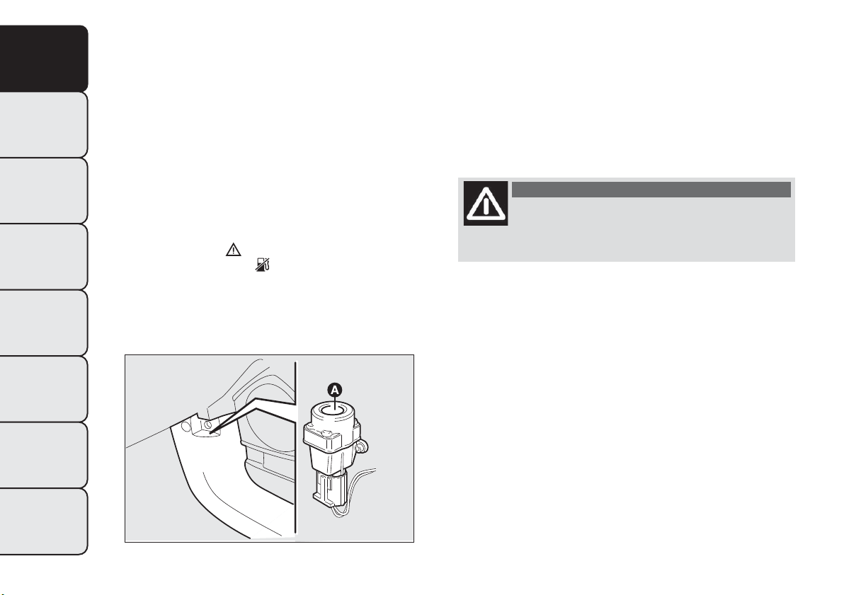
FUEL CUT-OFF SWITCH
(as an alternative to the fuel cut-off system, for
versions/markets where provided)
It is located in the bottom, near the passenger side
pillar fig. 48. It is triggered in the event of an impact,
causing:
❒ the fuel supply cut-off with the engine
consequently switching off;
❒ the automatic unlocking of the doors;
❒ the interior lights being switched on (for about 15
minutes).
The intervention of the switch is indicated by the
switching on of the
warning light on the
instrument panel or the
symbol on the display
(together with a message) (see “Warning lights and
messages” section).
Carefully check the car for fuel leaks, for instance in
the engine compartment, under the car or near
the tank area.
If no fuel leaks are found and the car can be started
again, press button A to reactivate the fuel system
and the lights.
After a collision, turn the ignition key to STOP to
prevent the battery from running down.
WARNING
If, after a collision, you smell fuel or
notice leaks from the fuel supply system,
do not reset the switch to avoid fire risk.
fig. 48
F0Q0638
64
GETTING TO
KNOW YOUR CAR
SAFETY
STARTING AND
DRIVING
WARNING LIGHTS
AND MESSAGES
IN AN EMERGENCY
SERVICING AND
MAINTENANCE
TECHNICAL
SPECIFICATIONS
INDEX
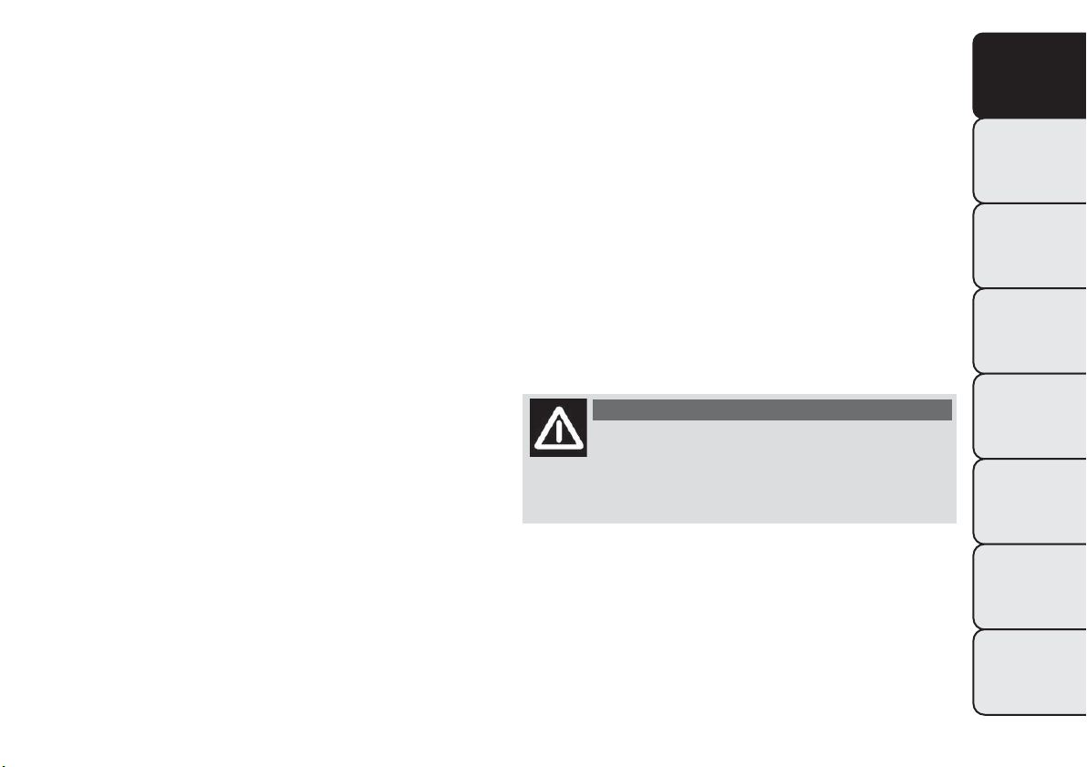
FUEL CUT-OFF SYSTEM
(as an alternative to the fuel cut-off switch, for
versions/markets where provided)
It is triggered in the event of a collision, causing:
❒ the fuel supply cut-off with the engine
consequently switching off;
❒ the automatic unlocking of the doors;
❒ the interior lights being switched on.
The intervention of the system is indicated by a
message shown on the display.
Carefully check the car for fuel leaks, for instance in
the engine compartment, under the car or near
the tank area.
After a collision, turn the ignition key to STOP to
prevent the battery from running down.
The following procedure should be carried out to
restore the correct operation of the vehicle:
❒ turn the ignition key to the MAR-ON position;
❒ turn on the right direction indicator;
❒ turn off the right direction indicator;
❒ turn on the left direction indicator;
❒ turn off the left direction indicator;
❒ turn on the right direction indicator;
❒ turn off the right direction indicator;
❒ turn on the left direction indicator;
❒ turn off the left direction indicator;
❒ turn the ignition key to the OFF position;
❒ turn the ignition key to the MAR-ON position.
WARNING
If, after an impact, you smell fuel or
notice leaks from the fuel supply system,
do not reactivate the system to avoid the risk of
fire.
65
GETTING TO
KNOW YOUR CAR
SAFETY
STARTING AND
DRIVING
WARNING LIGHTS
AND MESSAGES
IN AN EMERGENCY
SERVICING AND
MAINTENANCE
TECHNICAL
SPECIFICATIONS
INDEX
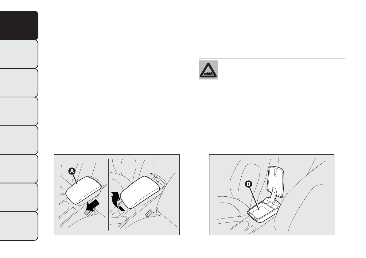
INTERIOR FITTINGS
FRONT ARMREST WITH STORAGE
COMPARTMENTS
(for versions/markets, where provided)
This is located between the front seats. A storage
compartment and cooled drinks compartment
are located inside the armrest (for versions/markets,
where provided) (see following paragraphs).
The armrest can be adjusted lengthwise through the
cover A fig. 49.
Storage compartment
Cover A fig. 49 can only be opened with the armrest
fully lowered and attached.
To access storage compartment B fig. 50, lift up
cover A.
Do not spill your drinks: in any case, a
hole at the bottom of the compartment
allows, if necessary, for spilled liquids
to drain outside the car.
fig. 49
F0Q0631
fig. 50
F0Q0632
66
GETTING TO
KNOW YOUR CAR
SAFETY
STARTING AND
DRIVING
WARNING LIGHTS
AND MESSAGES
IN AN EMERGENCY
SERVICING AND
MAINTENANCE
TECHNICAL
SPECIFICATIONS
INDEX
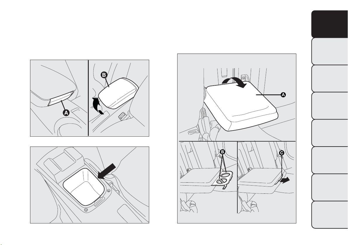
Cooled drinks compartment
Press button A fig. 51 and lift up armrest B: you can
then access the cooled drinks compartment fig. 52.
IMPORTANT The function of the compartment is to
maintain the temperature of the drinks that are put
in, which should be heated or cooled beforehand.
REAR ARMREST
(for versions/markets, where provided)
To use armrest A fig. 53, lower it as shown in the
diagram.
fig. 51
F0Q0634
fig. 52
F0Q0633
fig. 53
F0Q0010
67
GETTING TO
KNOW YOUR CAR
SAFETY
STARTING AND
DRIVING
WARNING LIGHTS
AND MESSAGES
IN AN EMERGENCY
SERVICING AND
MAINTENANCE
TECHNICAL
SPECIFICATIONS
INDEX
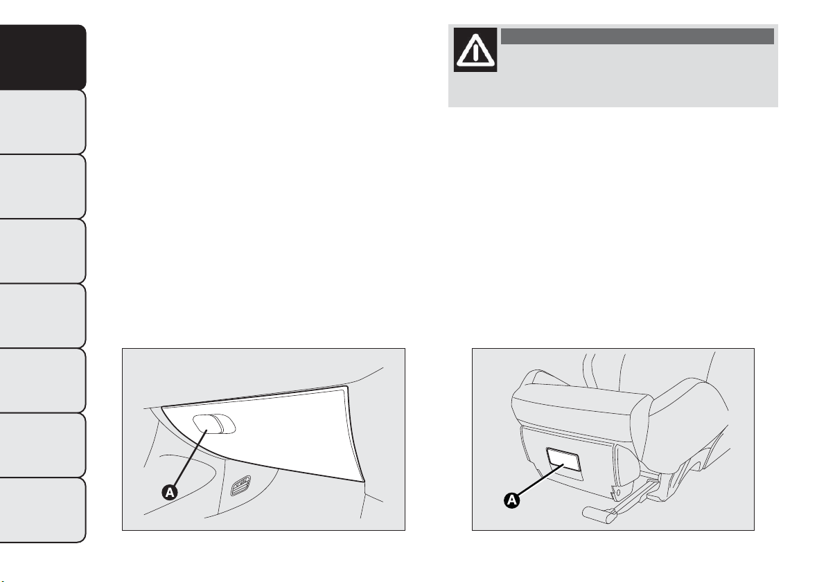
There are two cup and/or can holders B in the
armrest. To use these, pull tab C in the direction
shown by the arrow.
A storage compartment is available inside the
armrest; this can be accessed by raising the flap.
STORAGE COMPARTMENTS
Passenger side compartment
To open this compartment, operate handle A fig. 54,
as shown by the arrow.
When the compartment is opened a courtesy light
comes on inside which remains on for about 15
minutes with the ignition key in the STOP position.
If, during this period, a door or the tailgate is
opened, the 15 minute timing is reset.
WARNING
Never travel with the glove
compartment open: it could injure the
passenger in the event of a crash.
Compartment under the seat
(for versions/markets, where provided)
On some versions, under the passenger’s seat there
is a storage compartment: do not use it for objects
heavier than 1.5 kg.
To open the compartment, use handle A fig. 55.
fig. 54
F0Q0635
fig. 55
F0Q0012
68
GETTING TO
KNOW YOUR CAR
SAFETY
STARTING AND
DRIVING
WARNING LIGHTS
AND MESSAGES
IN AN EMERGENCY
SERVICING AND
MAINTENANCE
TECHNICAL
SPECIFICATIONS
INDEX
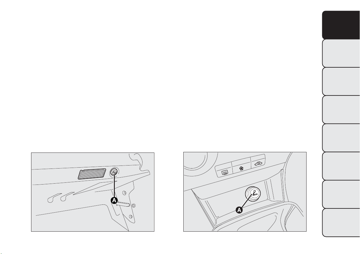
POWER SOCKET (12 V)
It is located on the central tunnel and is only
operational when the ignition key is turned to
MAR-ON. If a smokers' kit is requested, the socket
is replaced by a cigar lighter (see next paragraph).
On some versions an additional power socket A
fig. 56 is provided in the luggage compartment.
CIGAR LIGHTER
(for versions/markets, where provided)
This is located on the central tunnel.
Press button A fig. 57 to switch on the cigar lighter
when the ignition key is turned to MAR-ON.
After a few seconds the button automatically returns
to its initial position, and the cigar lighter is ready
for use.
IMPORTANT Always check that the cigar lighter is
switched off.
IMPORTANT The cigar lighter becomes very hot.
Handle it carefully and make sure that children don't
touch it: risk of fire and/or burning.
fig. 56
F0Q0016
fig. 57
F0Q0629
69
GETTING TO
KNOW YOUR CAR
SAFETY
STARTING AND
DRIVING
WARNING LIGHTS
AND MESSAGES
IN AN EMERGENCY
SERVICING AND
MAINTENANCE
TECHNICAL
SPECIFICATIONS
INDEX
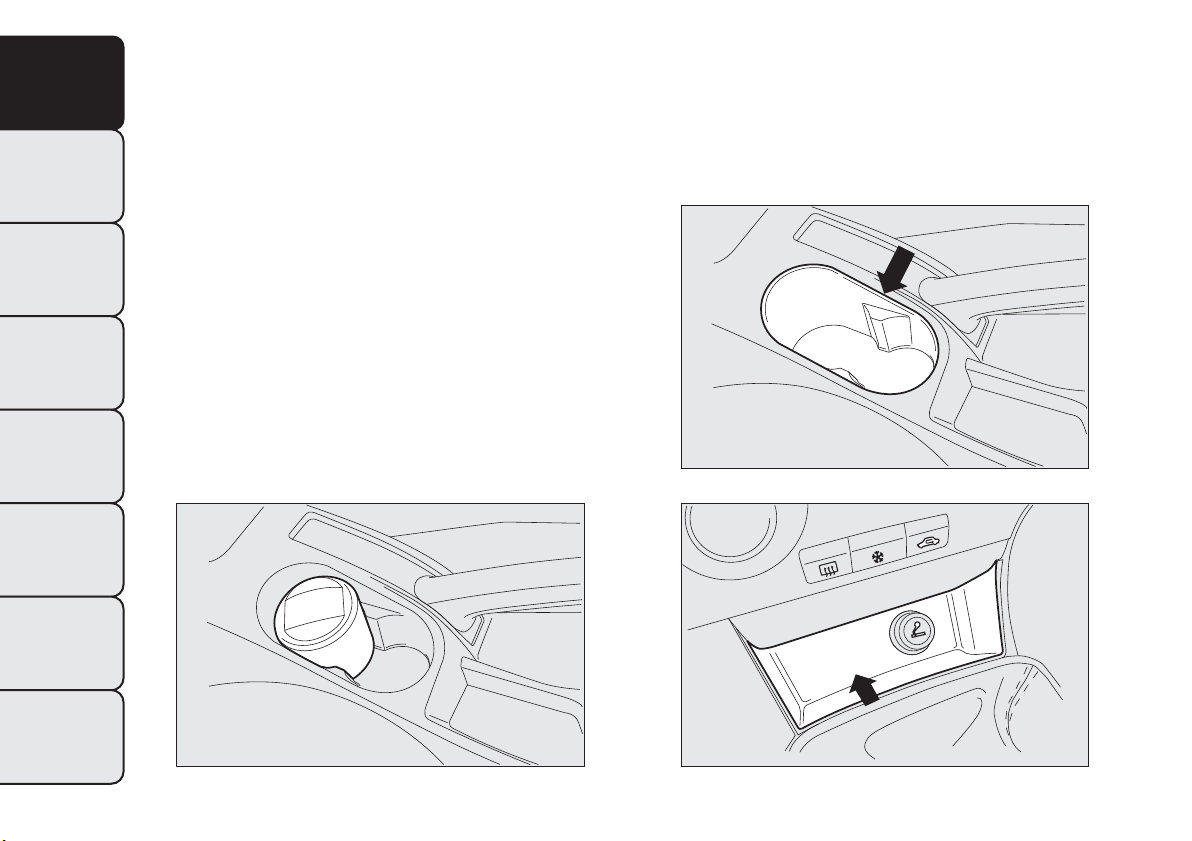
ASHTRAY
(for versions/markets, where provided)
The ashtray is a removable spring-loaded plastic box
fig. 58 that can be fitted into the cup/can holders
on the central tunnel.
IMPORTANT Do not use the ashtray as a waste
paper basket: it may catch fire in contact with
cigarette stubs.
GLASS HOLDER
The central tunnel has two cup and/or can holders
fig. 59.
STORAGE COMPARTMENTS
These are located next to the cigar lighter fig. 60,
near the handbrake lever fig. 61, on the front and
rear doors fig. 62 and fig. 63.
fig. 58
F0Q0630
fig. 59
F0Q0671
fig. 60
F0Q0672
70
GETTING TO
KNOW YOUR CAR
SAFETY
STARTING AND
DRIVING
WARNING LIGHTS
AND MESSAGES
IN AN EMERGENCY
SERVICING AND
MAINTENANCE
TECHNICAL
SPECIFICATIONS
INDEX
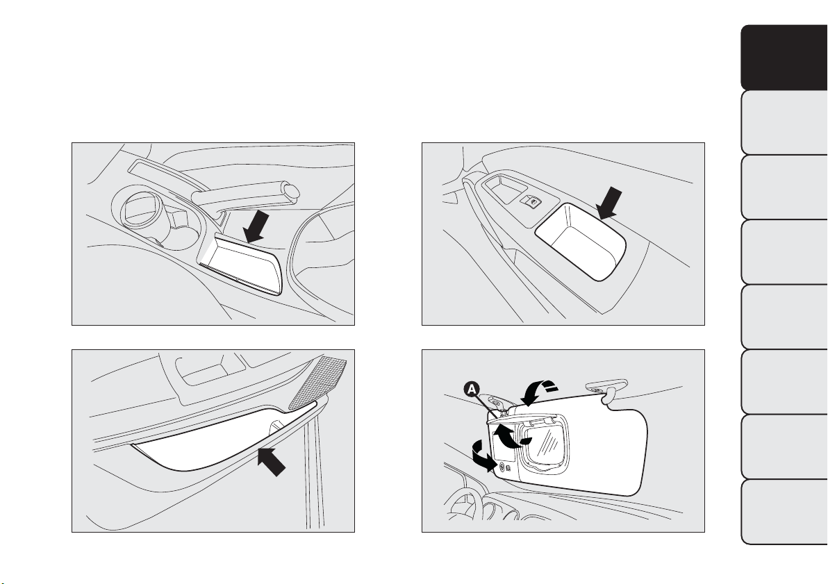
SUN VISORS
Driver's side
A courtesy mirror may be fitted to the sun visor on
some versions.
Passenger side
A courtesy mirror is fitted to the sun visor (on some
versions, the mirror is lit by a courtesy light).
The driver and passenger sun visors can be moved
back and forth and to the side fig. 64.
fig. 61
F0Q0673
fig. 62
F0Q0674
fig. 63
F0Q0676
fig. 64
F0Q0675
71
GETTING TO
KNOW YOUR CAR
SAFETY
STARTING AND
DRIVING
WARNING LIGHTS
AND MESSAGES
IN AN EMERGENCY
SERVICING AND
MAINTENANCE
TECHNICAL
SPECIFICATIONS
INDEX

On some versions, a courtesy mirror with courtesy
light is fitted on the back of the visors. The light
allows the mirror to be used even in poor visibility
conditions.
Lift cover A to access the mirror.
If the ignition key is at STOP position, the light stays
on for about 15 minutes. If, during this period, a
door or the tailgate is opened, the 15 minute timing
is reset.
IMPORTANT On both sides of the sun visor there is
a label remembering that it is compulsory to
deactivate the airbags if a rearward facing child
restraint system is fitted. Always comply with the
instructions on the sun visor. (see the "Front airbags"
paragraph in chapter "Safety").
SUN ROOF
(for versions/markets, where provided)
The large electric sun roof comprises two panes of
glass, one of which is mobile and the other fixed.
These are equipped with two
sun blinds (front and rear) that can be moved
manually.
The sun blinds be used in "fully closed" or "fully
open" positions (they have no fixed intermediate
positions).
To open the sun blinds: grip handle A fig. 65, release
it and move it in the direction of the arrows to
the "fully open" position.
To close them, carry out the procedure in reverse.
The sun roof can be operated only with the ignition
key turned to MAR-ON. The controls A and B fig. 66
on the trim next to the front roof light operate the
sun roof opening/closing functions.
fig. 65
F0Q0737
72
GETTING TO
KNOW YOUR CAR
SAFETY
STARTING AND
DRIVING
WARNING LIGHTS
AND MESSAGES
IN AN EMERGENCY
SERVICING AND
MAINTENANCE
TECHNICAL
SPECIFICATIONS
INDEX
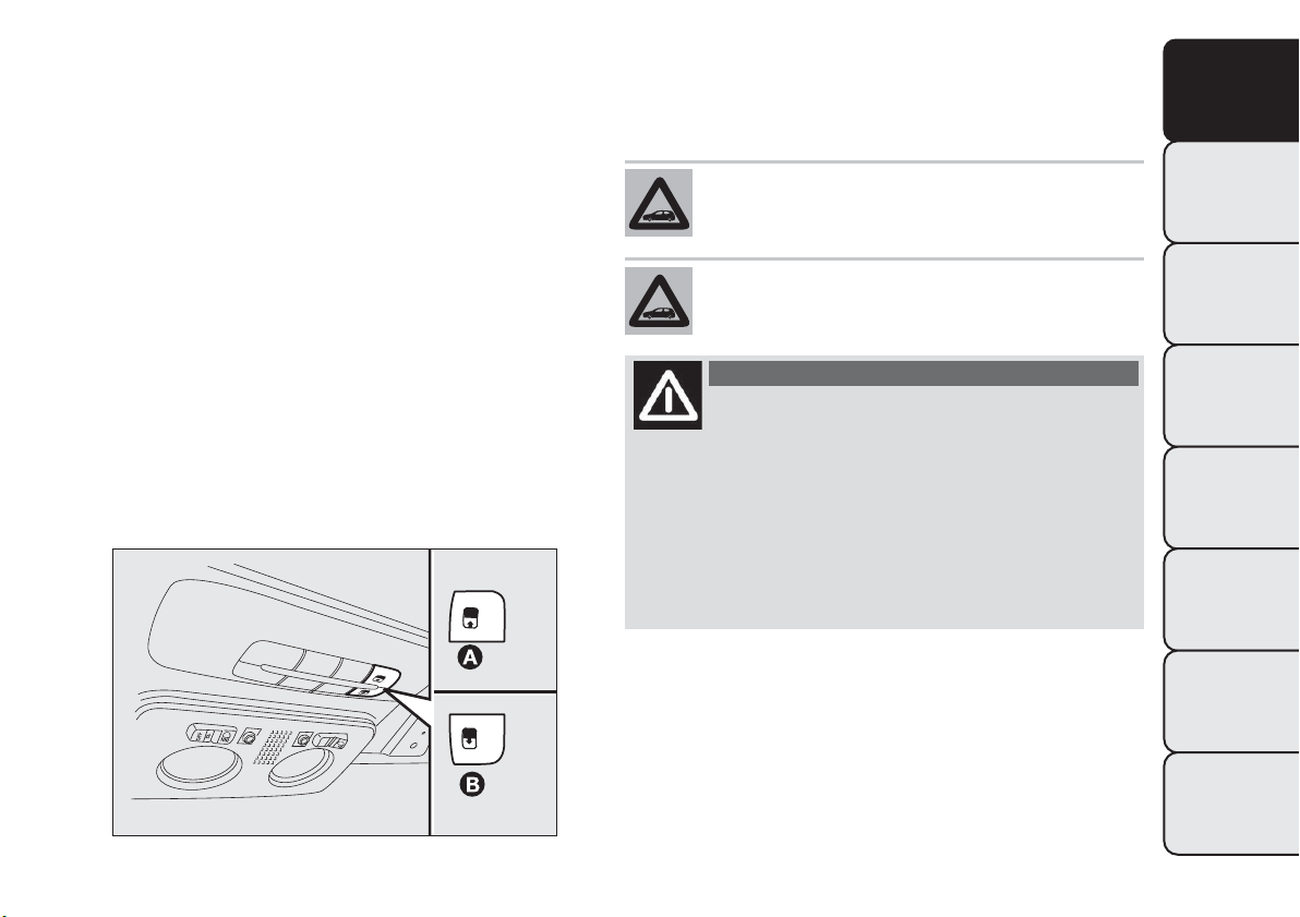
Opening
Press and hold down button B fig. 66. The front glass
panel will move into the spoiler position; press
button B once again and hold down for more than
half a second to automatically move the sun roof to
an intermediate position (“Comfort” position).
If the opening control is pressed again for more than
half a second, the roof will automatically continue
until it reaches the end of travel position; the roof
glass can be stopped in an intermediate position
by operating the button again.
Closing
With the roof in the fully open position, press
button A fig. 66 and, if the button is operated for
more than half a second, the front roof glass with
automatically assume the intermediate position
(“Comfort” position).
If the button is operated again for about half a
second the roof will assume the spoiler position.
Lastly, if the closing button is pressed again, the roof
will assume the fully closed position.
Use the sun roof only at “spoiler” position
if a transverse roof rack is fitted.
Do not open the sun roof if there is snow
or ice on it: you may damage it.
WARNING
When leaving the vehicle, always remove
the key from the ignition switch to
avoid the risk of injury to those still inside the
car due to accidental operation of the sun roof.
Improper use of the roof can be dangerous.
Before and during operation, always check that
no one is exposed to the risk of being injured
by the moving sun roof or by objects getting
caught or hit by it.
fig. 66
F0Q0678
73
GETTING TO
KNOW YOUR CAR
SAFETY
STARTING AND
DRIVING
WARNING LIGHTS
AND MESSAGES
IN AN EMERGENCY
SERVICING AND
MAINTENANCE
TECHNICAL
SPECIFICATIONS
INDEX
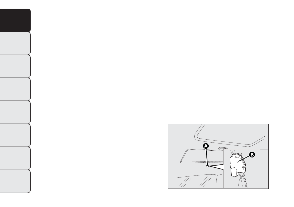
ANTI-PINCH SAFETY DEVICE
The sun roof has an anti-pinch safety system capable
of detecting the presence of an obstacle whilst the
roof is closing: if this happens, the system intervenes
and the movement of the glass is immediately
reversed.
INITIALISATION PROCEDURE
After the battery has been disconnected or a fuse
has blown, the operation of the sun roof must be
initialised again.
Proceed as follows:
❒ press button A fig. 66 until the roof is completely
closed. Release the button;
❒ press button A and keep it pressed for at least 10
seconds and/or until the glass panel clicks
forwards. Release the button at this point;
❒ press button A within 5 seconds of this operation
and keep it pressed: the glass panel will complete a
full opening and closing cycle. Only release the
button at the end of this cycle.
EMERGENCY MANOEUVRE
If the switch does not work, the sun roof can be
operated manually as follows:
❒ remove the protective cap A fig. 67 located on the
rear of the inner trim;
❒ take the Allen key supplied located in the
container housing the documentation or in the
luggage compartment (versions with automatic
Fix&Go);
❒ introduce the Allen key into housing B and turn:
clockwise to open the roof;
- anti-clockwise to close the roof.
fig. 67
F0Q0738
74
GETTING TO
KNOW YOUR CAR
SAFETY
STARTING AND
DRIVING
WARNING LIGHTS
AND MESSAGES
IN AN EMERGENCY
SERVICING AND
MAINTENANCE
TECHNICAL
SPECIFICATIONS
INDEX
-
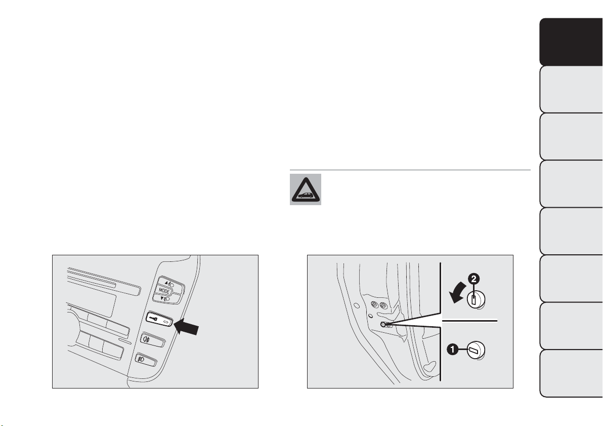
DOORS
CENTRAL LOCKING
From outside
With the doors closed, insert and turn the key in
one of the front door locks.
From inside
Press the door lock/release button fig. 68 located in
the dashboard, from inside the car (with the doors
shut).
If the electrical system has failed, it is still possible to
lock the doors manually.
IMPORTANT The rear doors cannot be opened
from the inside when the child lock device is
engaged.
CHILD LOCK DEVICE
This prevents the rear doors from being opened
from the inside.
Device fig. 69 can only be engaged with the doors
open:
❒ position1-device engaged (door locked);
❒ position2-device not engaged (door may be
opened from the inside).
The device remains on even if the doors are
unlocked electrically.
Always use this device when carrying
children.
fig. 68
F0Q0641
fig. 69
F0Q0677
75
GETTING TO
KNOW YOUR CAR
SAFETY
STARTING AND
DRIVING
WARNING LIGHTS
AND MESSAGES
IN AN EMERGENCY
SERVICING AND
MAINTENANCE
TECHNICAL
SPECIFICATIONS
INDEX
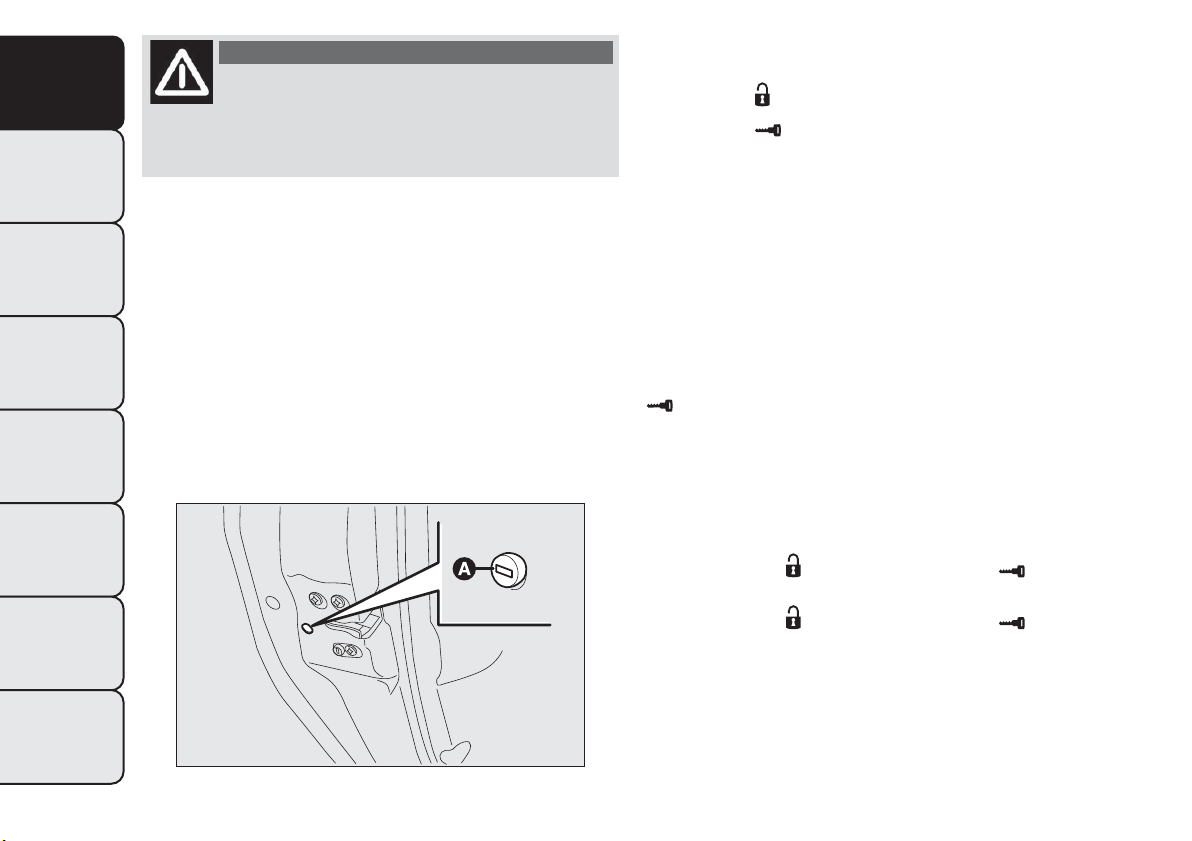
WARNING
After engaging the child lock on both
rear doors, check for proper engagement
by trying to open a rear door with the internal
handle.
REAR DOOR EMERGENCY LOCKING
DEVICE
The rear doors are fitted with an emergency device
that allows the doors to be locked when there is
no current.
Proceed as follows:
❒ insert the metal insert of the ignition key into
housing A fig. 70;
❒ turn the key clockwise and then remove it from
housing A.
The door lock knob can be realigned (only when the
battery charge has been restored) as follows:
❒ press the
button on the key;
❒ press the
button on the dashboard to
lock/unlock the doors;
❒ open a front door by inserting the key into the
door catch;
❒ operate the internal door handle.
IMPORTANT If the child lock device was engaged
and the previously described locking procedure
carried out, operating the internal handle will not
open the door but will only realign the door lock
knobs. To open the door, the outside handle must be
used. The door central locking/unlocking button
is not disabled by the engagement of the
emergency lock.
IMPORTANT If the battery is disconnected or the
protection fuse blows, the door opening/closing
mechanism must be initialised as follows:
❒ close all the doors;
❒ press button
on the key or button for
locking/unlocking the doors on the dashboard;
❒ press button
on the key or button for
locking/unlocking the doors on the dashboard.
fig. 70
F0Q0679
76
GETTING TO
KNOW YOUR CAR
SAFETY
STARTING AND
DRIVING
WARNING LIGHTS
AND MESSAGES
IN AN EMERGENCY
SERVICING AND
MAINTENANCE
TECHNICAL
SPECIFICATIONS
INDEX
WARNING
Do not activate the child lock device if
the rear doors emergency lock device
is already activated. If both have been
activated, you need to use the interior handle to
disengage the rear doors emergency locking
system and then open the door from the
outside.
ELECTRIC WINDOWS
They are fitted with a security system that can detect
the presence of an obstacle whilst the window is
closing; when this happens, the system kicks in and
the movement of the glass is immediately reversed.
IMPORTANT In the event that the anti-crushing
function is activated 5 times in only 1 minute, the
system will automatically enter the “recovery” mode
(self-protection). This condition is apparent from
the window closing in stages.
If this occurs, restore the system as follows:
❒ open the windows;
or
❒ turn the ignition key to the STOP position and
then to MAR-ON.
If no malfunction is present, the window returns to
its normal operation automatically.
IMPORTANT With the ignition key at STOP or
removed, the electric windows remain activated for
about two minutes and are deactivated as soon as
a door is opened.
WARNING
The system conforms to the 2000/4/EC
standard concerning the safety of
passengers leaning out of the passenger
compartment.
77
GETTING TO
KNOW YOUR CAR
SAFETY
STARTING AND
DRIVING
WARNING LIGHTS
AND MESSAGES
IN AN EMERGENCY
SERVICING AND
MAINTENANCE
TECHNICAL
SPECIFICATIONS
INDEX

IMPORTANT On some versions, when the button
on the key with remote control is pressed for longer
than 2 seconds the windows will open, whilst if the
button is pressed for longer than 2 seconds the
windows will close.
CONTROLS
Driver side front door fig. 71
Buttons have been provided on the driver's door
panel to control the following functions with the
ignition key turned to MAR-ON:
A
opening/closing front left window; “continuous
automatic” operation during window opening/
closing stage;
B
opening/closing front right window; “continuous
automatic” operation during window opening/
closing stage;
C
enabling/disabling of rear door electric window
controls;
D
opening/closing rear left window (for versions/
markets, where provided); “continuous automatic”
operation during window opening/closing stage;
E
opening/closing rear right window (for versions/
markets, where provided); “continuous automatic”
operation during window opening/closing stage.
Window opening
Push the buttons to open/close the desired window.
When one of the two buttons is pressed briefly,
the window moves in "stages"; if the button is held
down, "continuous automatic" operation is activated.
If the button is pressed again the window will stop
in its current position.
Window closing
Lift the buttons to close the desired window.
The window closing stage occurs following the same
logics described for the opening stage.
fig. 71
F0Q0622
78
GETTING TO
KNOW YOUR CAR
SAFETY
STARTING AND
DRIVING
WARNING LIGHTS
AND MESSAGES
IN AN EMERGENCY
SERVICING AND
MAINTENANCE
TECHNICAL
SPECIFICATIONS
INDEX
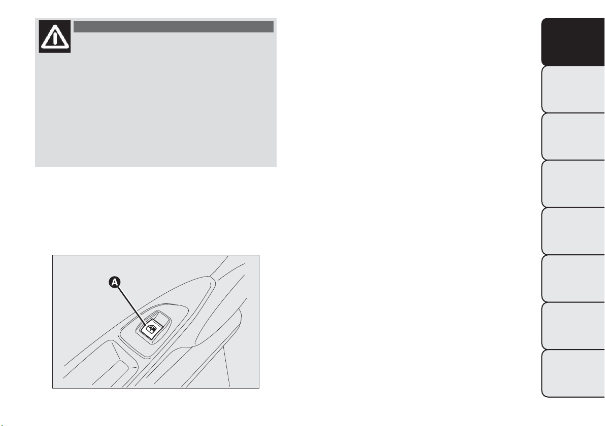
WARNING
Improper use of the electric windows
can be dangerous. Before and during
their operation ensure that any passengers are
not at risk from the moving glass either by
personal objects getting caught in the
mechanism or by being hit by it directly.When
leaving the car, always remove the ignition
key to prevent the electric windows from being
inadvertently activated, as this could present
a danger for the passengers remaining in the
vehicle.
Passenger side front door/rear doors
On the passenger side front door panel, and on
some versions also on the rear doors, buttons
A fig. 72 are provided to control the associated
windows.
ELECTRIC WINDOWS SYSTEM
INITIALISATION
The system must be re-initialised after disconnecting
the battery or if the relevant protection fuse is
blown.
Proceed as follows to start the electric window
initialisation:
❒ fully close the window to be initialised manually;
❒ after the window has reached the upper end
of travel, hold the up button pressed for at least
one second.
MANUAL REAR WINDOW MECHANISM
(for versions/markets, where provided)
To open and to close the window, use the relevant
handle.
fig. 72
F0Q0743
79
GETTING TO
KNOW YOUR CAR
SAFETY
STARTING AND
DRIVING
WARNING LIGHTS
AND MESSAGES
IN AN EMERGENCY
SERVICING AND
MAINTENANCE
TECHNICAL
SPECIFICATIONS
INDEX
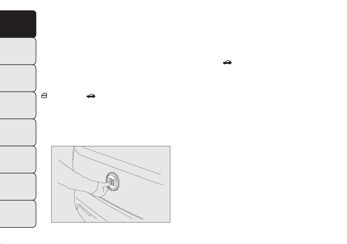
LUGGAGE COMPARTMENT
OPENING
When unlocked, the luggage compartment can be
opened from the outside the car by pressing the
electric logo fig. 73.
The tailgate can be opened at any time, if the doors
are unlocked.
The key with remote control should be used to open
the tailgate.
If the tailgate is not closed properly, the warning light
or the symbol switch on in the instrument
panel (together with the dedicated message on the
display) (see “Warning lights and messages” chapter).
Opening the tailgate will switch the luggage
compartment light on: the light will go off
automatically when closing the tailgate.
The light will stay on for about 15 minutes after
turning the key to STOP: if during this time, a door
or the tailgate is opened, the light will switch on
again for 15 minutes.
Opening the tailgate using the key with
remote control
Press button
even with alarm (for versions/
markets where provided) on.
Luggage compartment opening is indicated by the
double flashing of the direction indicators; tailgate
closing is indicated by single flashing (only with
the alarm switched on).
If the tailgate is opened when the alarm is on, the
system will:
❒ switch off the volume sensing protection;
❒ switch off the anti-lift protection;
❒ switch off the tailgate control sensor.
When the tailgate is closed again, all the functions
are restored.
CLOSING
Lower the tailgate, pressing near the lock until you
hear it click into place.
fig. 73
F0Q0680
80
GETTING TO
KNOW YOUR CAR
SAFETY
STARTING AND
DRIVING
WARNING LIGHTS
AND MESSAGES
IN AN EMERGENCY
SERVICING AND
MAINTENANCE
TECHNICAL
SPECIFICATIONS
INDEX
Do not fit additional objects onto the rear
parcel shelf or tailgate (speakers,
spoilers, etc.), except when contemplated
by the manufacturer, to ensure the correct
operation of the side gas shock absorbers of the
tailgate itself.
WARNING
Never exceed the maximum allowed
load in the luggage compartment (see
the "Technical data" chapter).Also make sure
that the objects you placed in the luggage
compartment have been properly secured, to
avoid them from being projected forward
following sudden braking, causing injury to
passengers.
WARNING
When travelling, do not put any object
on the rear parcel shelf because they
can injure passengers in the event of an
accident or sudden braking.
EXTENDING THE LUGGAGE
COMPARTMENT
The luggage compartment can be partially (1/3 or
2/3) or totally extended by splitting the rear seat.
81
GETTING TO
KNOW YOUR CAR
SAFETY
STARTING AND
DRIVING
WARNING LIGHTS
AND MESSAGES
IN AN EMERGENCY
SERVICING AND
MAINTENANCE
TECHNICAL
SPECIFICATIONS
INDEX
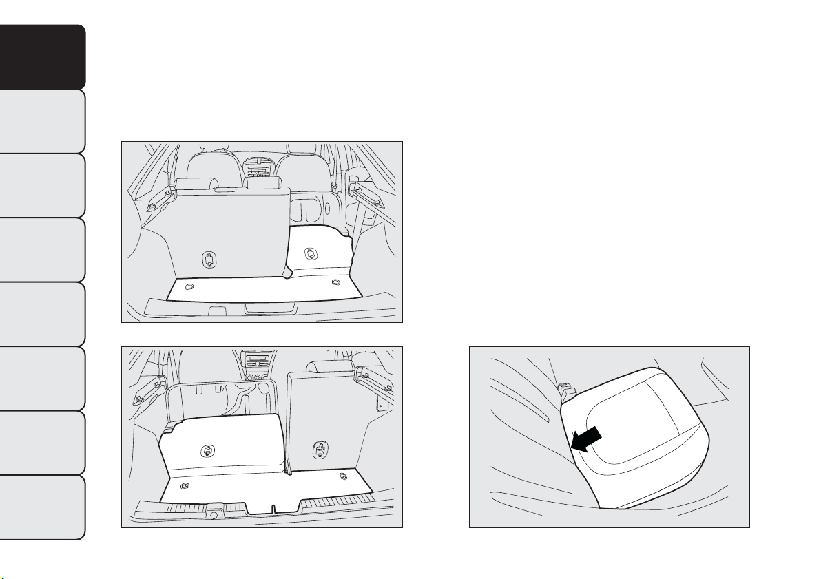
Partial extension (1/3 or 2/3) Fig. fig. 74-fig. 75
Extending the luggage compartment on the right
side makes it possible to carry two passengers
on the left part of the rear seat. Extending the left
side of the luggage compartment allows you to carry
one passenger on the right part of the rear seat.
Proceed as follows:
❒ completely lower the rear seat head restraints;
❒ move the seat belt to the side, making sure that it
is fully extended and not twisted;
❒ fold the desired cushion forwards fig. 76 working
in the point shown by the arrow;
❒ lift lever A fig. 77 retaining the backrest and fold
the latter forwards. When you lift the lever, you
will see a red band B.
Full extension
Tilting the rear seat completely forwards allows
maximum loading volume.
Proceed as follows:
❒ completely lower the rear seat head restraints;
❒ move the seat belts to the side, making sure that
they are correctly extended and not twisted;
fig. 74
F0Q0681
fig. 75
F0Q0682
fig. 76
F0Q0684
82
GETTING TO
KNOW YOUR CAR
SAFETY
STARTING AND
DRIVING
WARNING LIGHTS
AND MESSAGES
IN AN EMERGENCY
SERVICING AND
MAINTENANCE
TECHNICAL
SPECIFICATIONS
INDEX
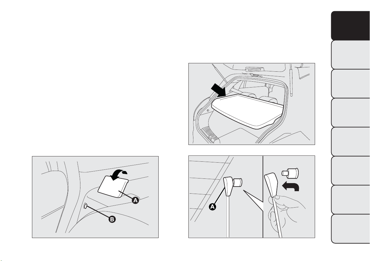
❒ fold the cushions forwards as described above;
❒ remove the rear parcel shelf fig. 78 and release the
upper ends of links A fig. 79 by removing the
eyelets from the pins and pushing them in the
direction indicated by the arrow;
❒ when the cushion is folded down, tilt the rear seat
backrests completely forwards as described above
so as to obtain a continuous loading surface.
REPOSITIONINGTHE REAR SEAT
Move the seat belts to the side, making sure that
they are correctly extended and not twisted.
Lift the backrests and push them back until you hear
both fastening mechanisms click in. Check that the
red band B fig. 80 on the side of levers A is no longer
visible.
The red band B indicates that the backrest is not
secured. Return the cushions to the horizontal
position holding the central seat fastening tongue
raised.
fig. 77
F0Q0683
fig. 78
F0Q0686
fig. 79
F0Q0687
83
GETTING TO
KNOW YOUR CAR
SAFETY
STARTING AND
DRIVING
WARNING LIGHTS
AND MESSAGES
IN AN EMERGENCY
SERVICING AND
MAINTENANCE
TECHNICAL
SPECIFICATIONS
INDEX
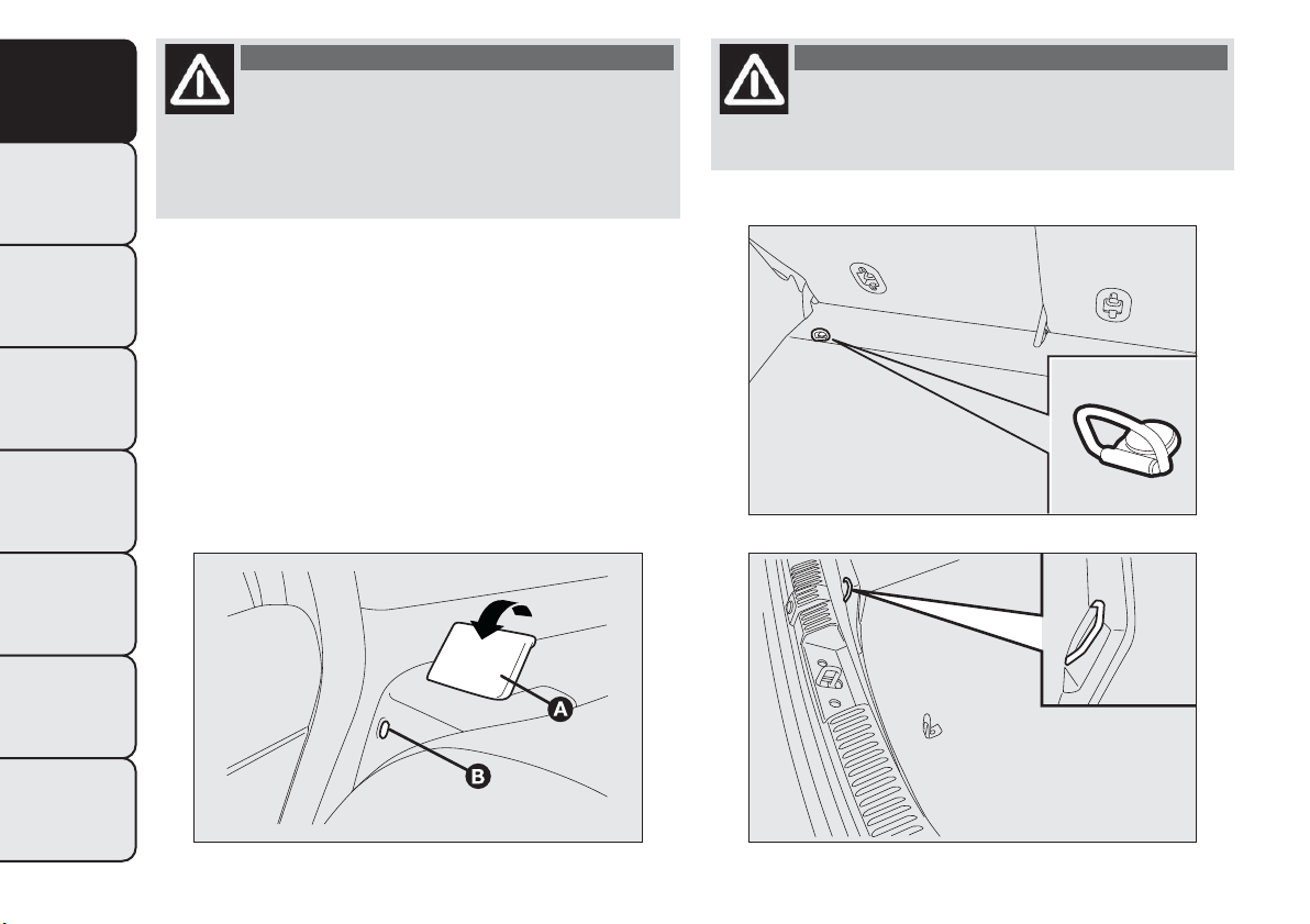
WARNING
Make sure that the backrest is correctly
secured on both sides (red bands B
fig. 80 not visible) to prevent it from moving
forward in the event of sharp braking, causing
injuries to passengers.
SECURINGYOUR LOAD
The luggage compartment contains two attachments
fig. 81 for the cables that secure the load transported
and another two attachments are located on the
rear crossmember fig. 82.
IMPORTANT Every attachment has a maximum load
capacity of 100 kg.
WARNING
A heavy load that has not been secured
may cause serious injuries to passengers
in the event of an accident.
fig. 80
F0Q0683
fig. 81
F0Q0685
fig. 82
F0Q0688
84
GETTING TO
KNOW YOUR CAR
SAFETY
STARTING AND
DRIVING
WARNING LIGHTS
AND MESSAGES
IN AN EMERGENCY
SERVICING AND
MAINTENANCE
TECHNICAL
SPECIFICATIONS
INDEX
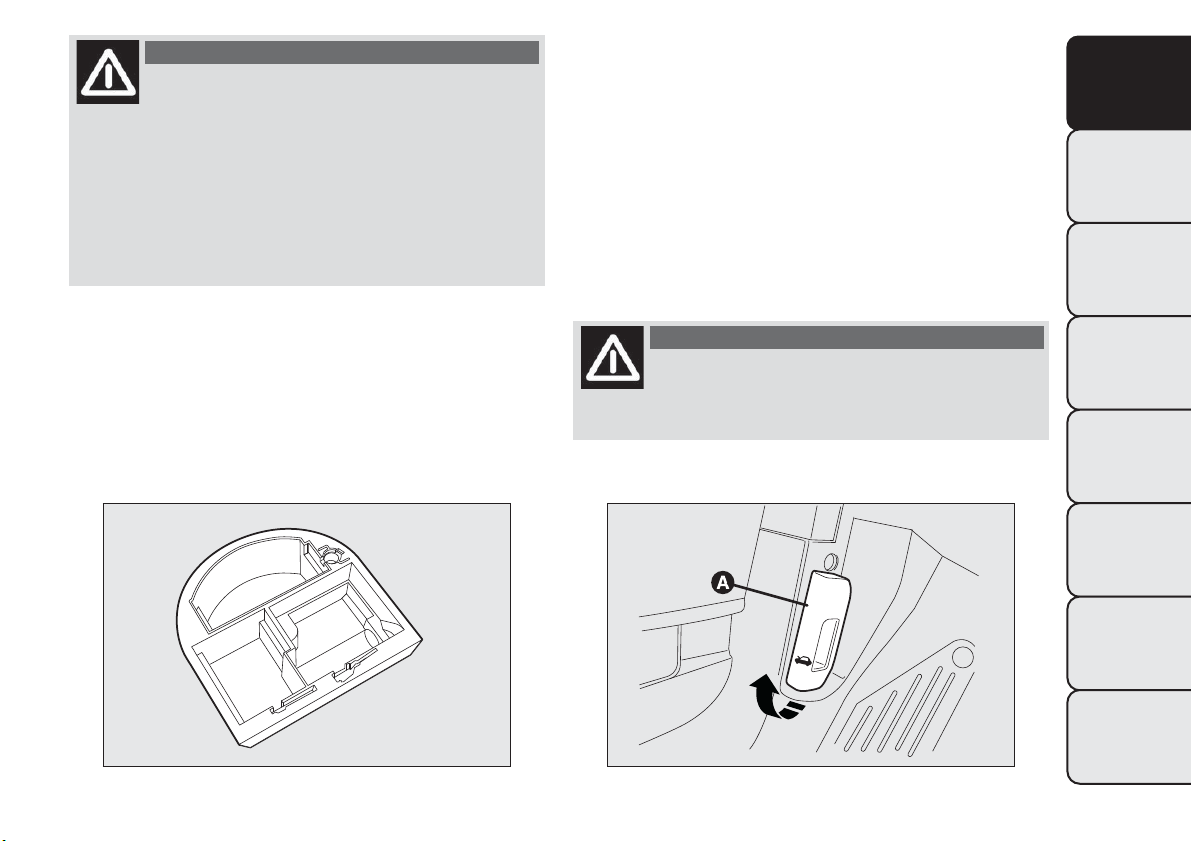
WARNING
If you are t ravelling in an area with
limited opportunities for vehicle
refuelling and you wish to bring fuel with you in
a petrol can, you must do so in compliance
with current regulations and using an approved
can, appropriately secured to the load securing
attachments.Anyway, by doing so, you increase
the risk of fire in case of an accident with
your vehicle.
CARGO BOX
It consists of a preformed box fig. 83, which is
located in the luggage compartment and can be used
to store objects, making it possible to have a flat
loading surface.
BONNET
OPENING
Proceed as follows:
❒ pull lever A fig. 84 in the direction indicated by the
arrow;
❒ pull lever B fig. 85 and lift the bonnet.
❒ lift the bonnet and, at the same time, release the
bonnet stay C fig. 86 from its locking device, then
insert the end of the stay into the housing D.
WARNING
The bonnet may dro p suddenly if the
supporting rod is not positioned
correctly.
fig. 83
F0Q0002
fig. 84
F0Q0689
85
GETTING TO
KNOW YOUR CAR
SAFETY
STARTING AND
DRIVING
WARNING LIGHTS
AND MESSAGES
IN AN EMERGENCY
SERVICING AND
MAINTENANCE
TECHNICAL
SPECIFICATIONS
INDEX
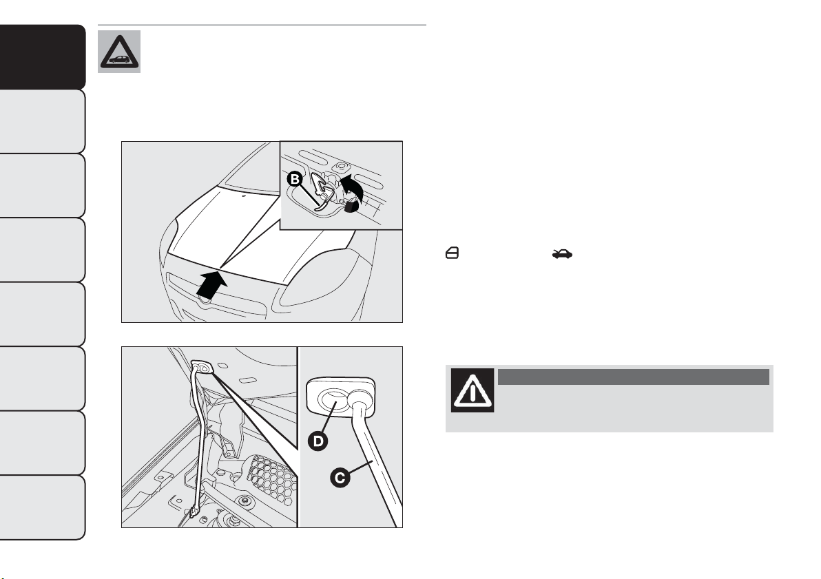
Use both hands to lift the bonnet. Before
lifting, check that the windscreen wiper
arms are not raised from the windscreen,
that the car is stationary and that the handbrake
is engaged.
CLOSING
Proceed as follows:
❒ hold the bonnet up with one hand and with the
other remove the stay C fig. 86 from the housing
D and fit it back in its locking device;
❒ lower the bonnet to approximately 20 centimetres
from the engine compartment and let it drop.
Make sure that the bonnet is completely closed
and not only fastened by the safety catch by trying
to open it. If it is not perfectly closed, do not try
to press the bonnet lid down but open it and
repeat the procedure.
If the bonnet is not closed properly, the warning light
or the symbol switch on in the instrument
panel (together with the dedicated message on the
display) (see “Warning lights and messages” chapter).
IMPORTANT Always check that the bonnet is closed
correctly to avoid it opening while the car is
travelling.
WARNING
Perform these operations only when the
car is stationary.
fig. 85
F0Q0690
fig. 86
F0Q0748
86
GETTING TO
KNOW YOUR CAR
SAFETY
STARTING AND
DRIVING
WARNING LIGHTS
AND MESSAGES
IN AN EMERGENCY
SERVICING AND
MAINTENANCE
TECHNICAL
SPECIFICATIONS
INDEX
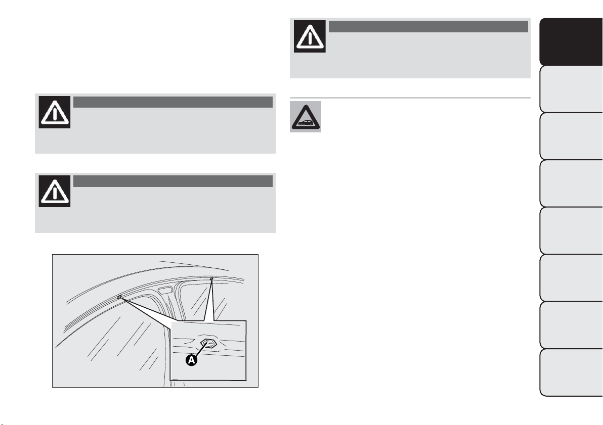
ROOF RACK/SKI RACK
The attachments provided are located in the areas
illustrated in fig. 87 and are only accessible with
the doors open. Lineaccessori Fiat has a dedicated
roof rack/ski rack for this car.
WARNING
After travelling for a few kilometres,
check to ensure that t he fixing screws
for the attachments are well tightened.
WARNING
Never exceed the maximum permitted
loads (see chapter "Technical
specifications").
WARNING
Evenly distribute the load and take into
account, when driving, the increased
responsiveness of the car to side wind.
Fully comply with the regulations in force
concerning maximum clearance.
fig. 87
F0Q0785
87
GETTING TO
KNOW YOUR CAR
SAFETY
STARTING AND
DRIVING
WARNING LIGHTS
AND MESSAGES
IN AN EMERGENCY
SERVICING AND
MAINTENANCE
TECHNICAL
SPECIFICATIONS
INDEX
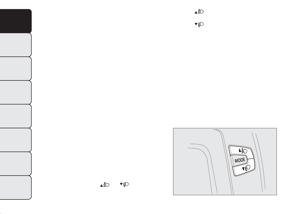
HEADLIGHTS
LIGHT BEAM DIRECTION
The correct aiming of the headlights is important for
the comfort and safety of not only the driver but
all other road users. This is also covered by a specific
rule of the highway code.
The headlights must be correctly aligned to
guarantee the best visibility conditions for all drivers
while travelling with headlights on.
Contact a Fiat Dealership to have the lights checked
and adjusted, if necessary.
IMPORTANT When the gas discharge (Xenon)
headlamps (for versions/markets, where provided)
are switched on, normally parabolas and light beam
move vertically for about 2 seconds until headlamp
alignment has stabilised.
HEADLIGHT ALIGNMENT CORRECTOR
This device works with the ignition key in the
MAR-ON position and the dipped beam headlights
on.
The car will tilt backwards when it is loaded, raising
the light beam. The beams must therefore be
realigned in this case.
Adjusting headlights alignment
For adjusting, press buttons
and fig. 88 on
the dashboard.
Press button
to increase the light beam of one
position.
Press button
to decrease the light beam of one
position.
The display shows the position while adjusting.
Correct positions depending on the load
Position 0
one or two occupants in the front seats.
Position 1
five people
Position 2
five people with a load in the luggage
compartment
Position 3
driver + maximum permitted load stowed
in the luggage compartment.
IMPORTANT Check the headlight alignment each
time the weight of the load transported changes.
fig. 88
F0Q0644
88
GETTING TO
KNOW YOUR CAR
SAFETY
STARTING AND
DRIVING
WARNING LIGHTS
AND MESSAGES
IN AN EMERGENCY
SERVICING AND
MAINTENANCE
TECHNICAL
SPECIFICATIONS
INDEX
IMPORTANT If the car is equipped with (Xenon) gas
discharge headlights, the headlight alignment is
controlled electronically, as a consequence
the
and buttons are not present.
FOG LIGHT ALIGNMENT
Contact a Fiat Dealership to have the lights checked
and adjusted, if necessary.
ADJUSTING THE HEADLIGHTS WHEN
ABROAD
The dipped beam headlights are aligned for operation
in the country where the vehicle was originally
purchased. When in countries where you drive on
the other side of the road, you need to alter the
beam direction by affixing a specially designed
self-adhesive film in order not to dazzle the vehicles
travelling in the opposite direction.
Such film is provided by Lineaccessori Fiat and is
available at Fiat Dealerships.
ABS SYSTEM
ABS is an integral part of the braking system which
prevents, whatever the road conditions and force
applied to the brake pedal, the wheels from locking
and consequently sliding under braking, thus ensuring
that the vehicle remains under control even during
emergency braking.
The EBD system (Electronic Braking Force
Distribution) completes the system allowing the
brake force to be distributed between the front and
rear wheels.
IMPORTANT To obtain the maximum efficiency of
the braking system, a bedding-in period of about 500
km is needed: during this period it is better to
avoid sharp, repeated and prolonged braking.
WARNING
The ABS gets the most from the
available grip, but it cannot improve it;
you should therefore take every care when
driving on slippery surfaces and not take
unnecessary r isks.
SYSTEM INTERVENTION
The driver can feel that the ABS system has come
into action because the brake pedal pulsates slightly
and the system gets noisier: it means that the car
speed should be altered to suit the type of road
surface.
89
GETTING TO
KNOW YOUR CAR
SAFETY
STARTING AND
DRIVING
WARNING LIGHTS
AND MESSAGES
IN AN EMERGENCY
SERVICING AND
MAINTENANCE
TECHNICAL
SPECIFICATIONS
INDEX
WARNING
When the ABS cuts in and you feel the
brake pedal pulsating, do not raise
your foot, but keep it pressed; in doing so you
will stop in the shortest amount of space
possible depending on the current road
conditions.
WARNING
If the ABS intervenes, it is a sign that the
grip between tyre and the road surface
has reached the limit: you must slow down to
adapt the speed to the road grip available.
ABS FAILURE INDICATION
This is indicated by the
warning light on the
instrument panel together with the dedicated
message on the multifunction display (for versions/
markets where available) coming on (see “Warning
lights and messages” section).
In the case, the braking system will work as normal
without the extra capacity offered by the ABS
system. Drive carefully to the nearest Fiat Dealership
to have the system checked.
EBD FAILURE INDICATION
This is indicated by the warning lights
and on
the instrument panel together with the dedicated
message on the multifunction display (for
versions/markets where available) coming on (see
“Warning lights and messages” section).
In this case, the rear wheels may suddenly lock and
the vehicle may swerve when braking sharply. Drive
carefully to the nearest Fiat Dealership to have
the system checked.
WARNING
If only the warning light
on the
instrument panel switches on - together
with a message in the multifunction display (for
versions/markets, where provided) - stop the
car immediately and contact the nearest Fiat
Dealership. Fluid leaking from the hydraulic
system will compromise the operation of the
braking system, whether it is of the conventional
type or with ABS.
90
GETTING TO
KNOW YOUR CAR
SAFETY
STARTING AND
DRIVING
WARNING LIGHTS
AND MESSAGES
IN AN EMERGENCY
SERVICING AND
MAINTENANCE
TECHNICAL
SPECIFICATIONS
INDEX

BRAKE ASSIST
(emergency braking assistance)
(for versions/markets, where provided)
The system, which cannot be turned off, recognises
emergency braking (on the basis of the brake pedal
operating speed) and speeds up the response of
the braking system.
Brake Assist is deactivated on the versions equipped
with ESP, in the event of ESP system failure, indicated
by warning light
coming on together with the
message on the display.
ESP SYSTEM
(Electronic Stability Program)
(for versions/markets, where provided)
This is an electronic system that controls car stability
in the event of tyre grip loss, helping maintain
directional control.
The ESP system is therefore particularly useful when
the grip conditions of road surfaces change.
With the ESP, the car is provided with ASR (traction
control with interventions on brakes and engine),
HILL HOLDER (device for starting on gradients
without using the brakes), MSR (control of engine
braking torque when shifting gear down) and HBA
(automatic increase of braking pressure in the case of
emergency braking).
SYSTEM INTERVENTION
It is signalled by the blinking of the warning light
on the instrument panel, to inform the driver that
the car is in critical stability and grip conditions.
SYSTEM ACTIVATION
The ESP system comes on automatically when the
vehicle is started and cannot be turned off.
91
GETTING TO
KNOW YOUR CAR
SAFETY
STARTING AND
DRIVING
WARNING LIGHTS
AND MESSAGES
IN AN EMERGENCY
SERVICING AND
MAINTENANCE
TECHNICAL
SPECIFICATIONS
INDEX
ESP SYSTEM FAILURE INDICATIONS
In the event of a failure, the ESP system will be
automatically switched off and warning light
will
switch on constantly on the instrument panel (on
some versions along with a message on the display,
see “Warning lights and messages” chapter). In
this case, contact a Fiat Dealership.
WARNING
Do not take unnecessary risks, even if
your vehicle is fitted with an ESP
system.Your driving style must always be suited
to the road conditions, visibility and traffic.
The driver is always responsible for road safety.
HILL HOLDER SYSTEM
(for versions/markets, where provided)
It's integral to the ESP system. It automatically
activates with the following conditions:
❒ uphill: vehicle stationary on a road with a gradient
higher than 5%, engine running, clutch and brake
pedals pressed and gearbox in neutral or gear
other than reverse engaged;
❒ downhill: car stationary on a road with a gradient
higher than 5%, engine running, clutch and brake
pedal pressed and reverse gear engaged.
When setting off the ESP system control unit will
keep brake force on wheels until the torque
necessary for starting is reached, or in any case for
max. 2 seconds in order to pass easily from the
brake pedal to the accelerator pedal.
When two seconds have elapsed, without starting,
the system is automatically deactivated, gradually
releasing the braking pressure. During this release
stage, the typical mechanical brake release noise can
be heard, indicating that the car is about to move.
HILL HOLDER SYSTEM FAILURE
INDICATIONS
A possible system failure is indicated by the
warning light on the instrument panel - together
with the dedicated message in the multifunction
display (for versions/markets, where provided) -
coming on (see "Warning lights and messages"
chapter).
IMPORTANT The Hill Holder system is not a parking
brake, therefore do not leave the car without
activating the handbrake, switching off the engine and
engaging first gear.
WARNING
If the space-saver wheel is used, the ESP
system keeps operating.Always
remember that the space-saver wheel, being
smaller than the original wheel, provides less
grip. For the correct operation of t he ESP and
ASR systems it is vital that the tyres are the
same make and the same type on all the
wheels, in perfect condition and, above all, the
recommended type, make and size.
92
GETTING TO
KNOW YOUR CAR
SAFETY
STARTING AND
DRIVING
WARNING LIGHTS
AND MESSAGES
IN AN EMERGENCY
SERVICING AND
MAINTENANCE
TECHNICAL
SPECIFICATIONS
INDEX
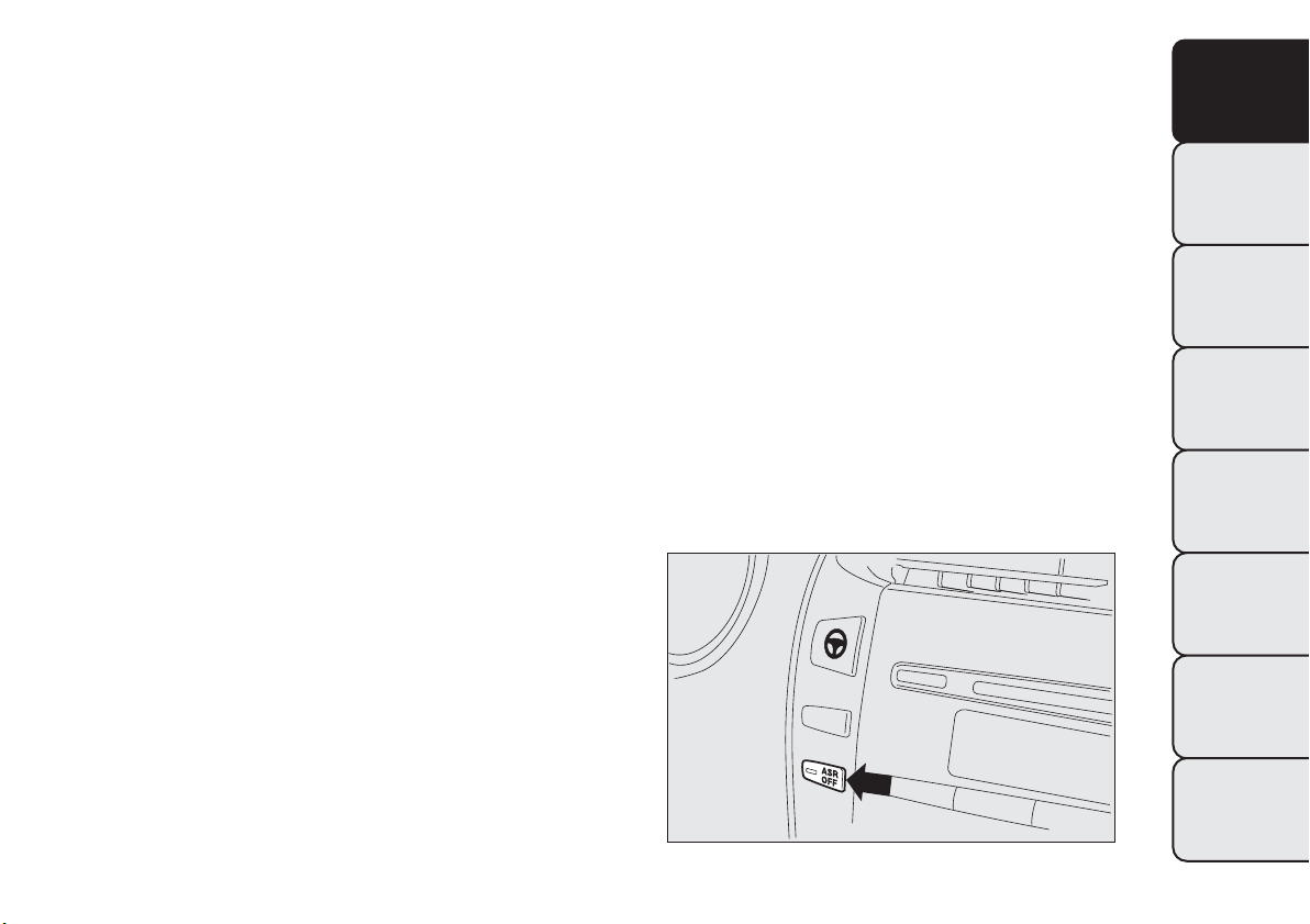
ASR SYSTEM (Antislip Regulation)
This is integral to the ESP system and automatically
intervenes if one or both drive wheels slip, helping
the driver to control the car.
Depending on the slipping conditions, two different
control systems are activated:
❒ if the slipping involves both drive wheels, the ASR
intervenes reducing the power transmitted by the
engine;
❒ if the slipping only involves one of the drive
wheels, the ASR intervenes automatically braking
the wheel that is slipping.
The action of the ASR system is particularly helpful
in the following circumstances:
❒ slipping of the inner wheel on bends due to
dynamic variations in the load or excessive
acceleration;
❒ excessive power transmitted to the wheels, also in
relation to road surface conditions;
❒ acceleration on slippery, snowy or icy road
surfaces;
❒ loss of grip on wet road surfaces (aquaplaning).
MSR SYSTEM (ENGINE DRIVE
REGULATION)
This is an integral part of the ASR system that, in the
event of a sudden gear downshifting, cuts in and
provides torque to the engine thus preventing
excessive drive wheel drive which, especially in poor
grip conditions, can lead to loss of stability.
ENGAGEMENT/DISENGAGEMENT OF THE
ASR SYSTEM
The ASR system switches on automatically each time
the engine is started.
When the system is active, a message is shown on
the display (see “Warning lights and messages”
chapter).
Whilst driving, the ASR can be deactivated and
subsequently activated again by pressing the ASR
OFF button on the dashboard, next to the steering
wheel.
Whilst driving, the ASR can be switched off and
subsequently switched on again by pressing button C.
fig. 89
F0Q0694
93
GETTING TO
KNOW YOUR CAR
SAFETY
STARTING AND
DRIVING
WARNING LIGHTS
AND MESSAGES
IN AN EMERGENCY
SERVICING AND
MAINTENANCE
TECHNICAL
SPECIFICATIONS
INDEX
Every time the ignition key is turned to MAR-ON
the ASR OFF button LED switches on for a few
seconds to indicate that the system is running a
diagnosis. The LED activation should not be
understood as a fault.
When the ASR is switched off, the button LED lights
up (along with a message on the display, see
“Warning lights and messages” chapter).
If the ASR is switched off when driving, it is
automatically switched on again when the vehicle is
started up.
When travelling on snowy roads with snow chains, it
may be helpful to turn the ASR off: in fact, in these
conditions, slipping of the drive wheels when moving
off makes it possible to obtain better traction.
Fault indications In the event of a fault, the ASR
system will be deactivated automatically and the
warning light will switch on constantly on the
instrument panel (together with a message on the
display) (see “Warning lights and messages” chapter).
In this case, contact a Fiat Dealership as soon as
possible.
WARNING
The ASR system will not operate when a
spare wheel is fitted: in this case, the
warning light will switch on constantly in the
instrument panel (together with a message on
the display) (see “Warning lights and messages”
chapter).
WARNING
For the correct operat ion of the ESP and
ASR systems all four tyres must be the
prescribed type and size, be all the same brand
and type on each wheel, and must be in
excellent condition.
94
GETTING TO
KNOW YOUR CAR
SAFETY
STARTING AND
DRIVING
WARNING LIGHTS
AND MESSAGES
IN AN EMERGENCY
SERVICING AND
MAINTENANCE
TECHNICAL
SPECIFICATIONS
INDEX

EOBD SYSTEM
The EOBD system (European On Board Diagnostic)
is a diagnosis system installed on the ECUs, which
detects and reports possible malfunctions in the
electronic systems that could worsen emissions.
The goal of the system is to:
❒ monitor the system efficiency;
❒ indicate an increase in emissions due to vehicle
malfunction;
❒ indicate the need to replace components which
have deteriorated.
It also alerts the driver, by turning on the warning
light
on the instrument panel (together with
relevant message on the display), when these
components are damaged; it can also report any
system malfunctions (see "Warning lights and
messages" chapter).
Note The car also has a connector that can be
interfaced with appropriate tools, which makes it
possible to read the error codes stored in the
electronic control units together with a series of
specific parameters for engine operation and
diagnosis. This check can also be carried out by the
traffic police.
IMPORTANT After an operation at the Fiat
Dealership, aimed at solving malfunctions linked to
the EOBD system, some bench tests should be
made, along with road tests if necessary, for a
complete check of the system. The latter may also
require the car to cover a long distance.
WIRING FOR RADIO SYSTEM
(for versions/markets, where provided)
The car may be equipped with a storage
compartment on the dashboard.
The radio must be installed in the place occupied by
the central storage compartment A fig. 90, where
you will find the wiring.
Press on the retaining devices under the central
storage compartment to extract the compartment.
WARNING
For connection to the radio system
set-up, contact a Fiat Dealership
to prevent any problem that could impair car
safety.
fig. 90
F0Q0691
95
GETTING TO
KNOW YOUR CAR
SAFETY
STARTING AND
DRIVING
WARNING LIGHTS
AND MESSAGES
IN AN EMERGENCY
SERVICING AND
MAINTENANCE
TECHNICAL
SPECIFICATIONS
INDEX
ACCESSORIES PURCHASED BY THE
OWNER
If after buying the car, you decide to install electrical
accessories that require a permanent electric supply
(radio, satellite anti-theft system, etc.) or accessories
that in any case burden the electric supply, contact
a Fiat Dealership, whose qualified personnel, besides
suggesting the most suitable devices from
Lineaccessori Fiat, will also evaluate the overall
electric consumption, checking whether the car's
electrical system is able to withstand the load
required, or whether it needs to be integrated with a
more powerful battery.
WARNING
Take care when fitting additional
spoilers, alloy wheels or non-standard
wheel hubs: they could reduce the ventilation of
the brakes and affect efficiency under sharp,
repeated braking or on long descents. Make
sure that nothing obstructs the pedal stroke
(mats, etc.)
INSTALLING ELECTRICAL/ELECTRONIC
DEVICES
Electrical and electronic devices installed after buying
the car in the context of after-sales service must
carry the label (see fig. 91):
Fiat Group Automobiles S.p.A. authorises the
installation of transceiver devices on condition that
such installations are carried out in a workmanlike
fashion, following the manufacturer’s instructions, at
a specialised centre.
IMPORTANT Traffic police may not allow the car on
the road if devices have been installed which modify
the features of the car. This may also cause
invalidation of warranty in relation to faults caused
by the change either directly or indirectly related
to it.
Fiat Group Automobiles S.p.A. shall not be liable for
damage caused by the installation of accessories
either not supplied or recommended by Fiat Group
Automobiles S.p.A. and/or not installed in
compliance with the provided instructions.
fig. 91
DISPOSITIVI-ELETTRONICI
96
GETTING TO
KNOW YOUR CAR
SAFETY
STARTING AND
DRIVING
WARNING LIGHTS
AND MESSAGES
IN AN EMERGENCY
SERVICING AND
MAINTENANCE
TECHNICAL
SPECIFICATIONS
INDEX
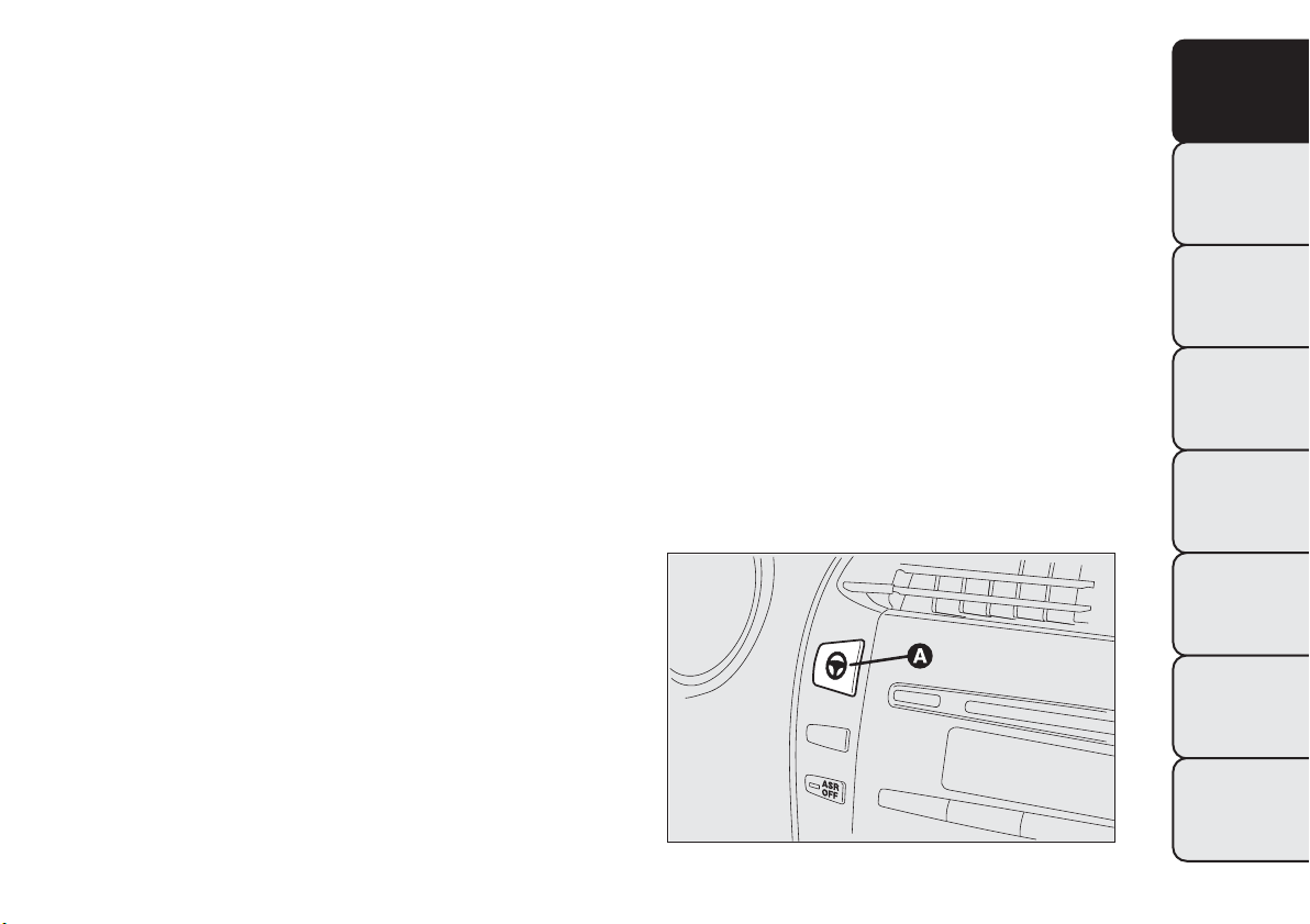
RADIO TRANSMITTERS AND MOBILE
PHONES
Radio transmitter equipment (vehicle mobile phones,
CB radios etc.) cannot be used inside the car unless
a separate aerial is mounted externally.
IMPORTANT The use of these devices inside the
passenger compartment (without an external aerial)
may cause the electrical systems to malfunction.
This could compromise the safety of the car in
addition to constituting a potential hazard for
passengers' health.
In addition, transmission and reception of these
devices may be negatively affected by the shielding
effect of the car body. As far as the use of
EC-approved mobile phones is concerned (GSM,
GPRS, UMTS), follow the usage instructions provided
by the mobile phone manufacturer.
"DUALDRIVE" ELECTRIC POWER
STEERING SYSTEM
The car is equipped with an electrically controlled
power steering system called “Dualdrive”, working
only with the ignition key at MAR-ON and the
engine running, that customises steering force
according to the driving conditions.
IMPORTANT When turning the ignition key quickly,
full power steering functionality can be achieved after
1-2 seconds.
ACTIVATION/DEACTIVATION
(CITY function)
(for versions/markets, where provided)
To turn the function on/off, press button A fig. 92 on
the dashboard, next to the steering wheel.
fig. 92
F0Q0693
97
GETTING TO
KNOW YOUR CAR
SAFETY
STARTING AND
DRIVING
WARNING LIGHTS
AND MESSAGES
IN AN EMERGENCY
SERVICING AND
MAINTENANCE
TECHNICAL
SPECIFICATIONS
INDEX
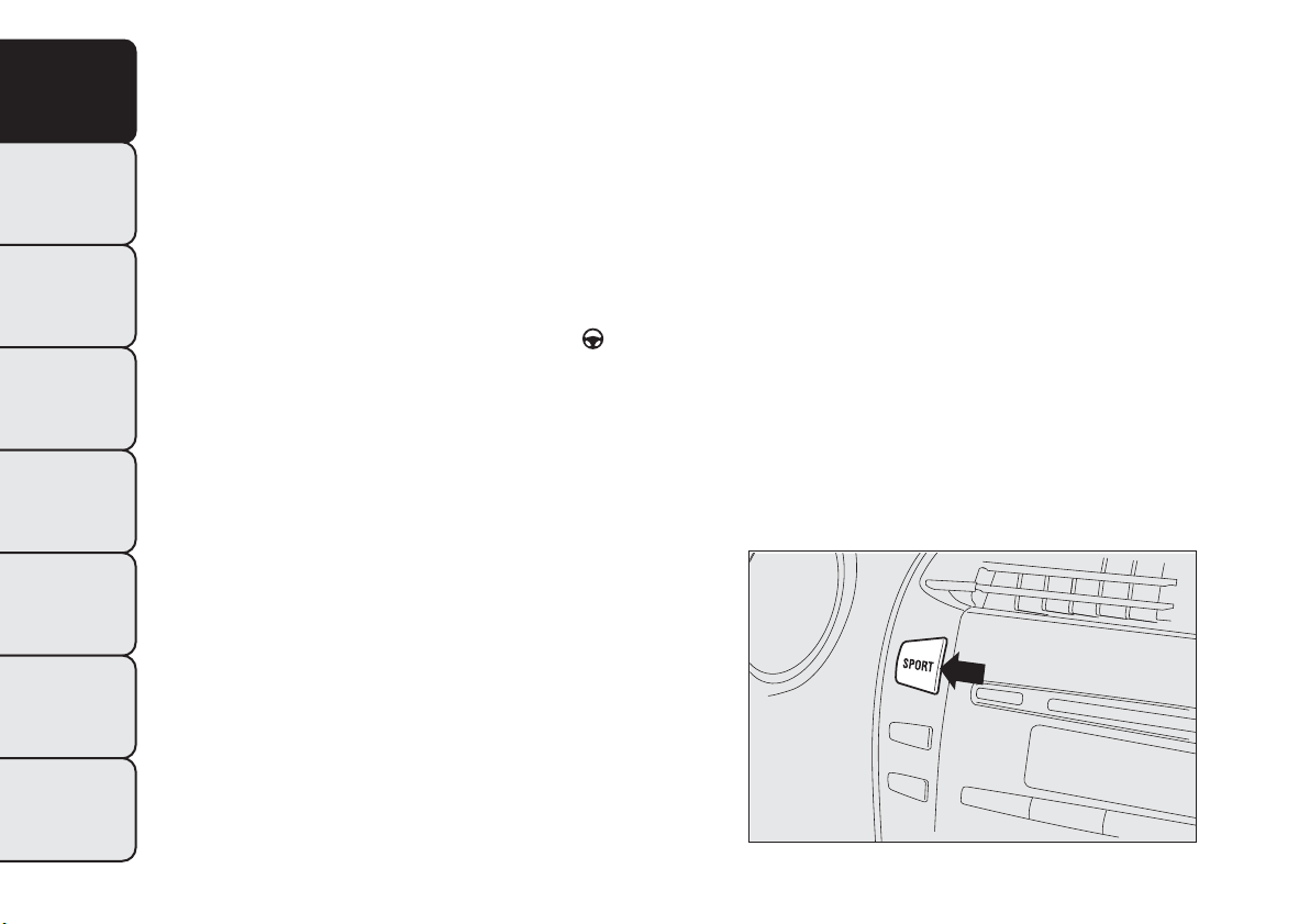
The activation of the function is signalled by the
word CITY on the display (in some versions it is
signalled by the switching on of the warning light
CITY).
When the CITY function is on, the steering wheel
effort is lighter and parking operations are easier:
therefore this function is particularly useful for
driving in city centres.
FAILURE INDICATIONS
Any failure of the electric power steering system is
indicated by instrument panel warning light
coming
on together with a message on the display (on
some versions together with a symbol on the display)
(see “Warning lights and messages” chapter).
In the event of electric power steering system failure,
the car can be driven with mechanical steering.
SPORT FUNCTION
(for versions/markets, where provided)
The vehicle may be equipped with a system that
allows a choice between two styles of driving, normal
and sports.
Pressing the SPORT button fig. 93 produces a sporty
driving setting characterised by higher acceleration
response and more effort required at the steering
wheel for a sporty driving sensation.
Pressing the SPORT button also activates the
turbocharger supercharging function (overboost).
Via this function the engine management control unit
allows - in relation to the position of the accelerator
pedal and for a limited time - maximum pressure
levels to be reached inside the turbocharger, with a
consequent increase in engine torque with respect to
that which is normally possible.
This function is particularly useful whenever
maximum performance is required for a short time
(e.g. when overtaking).
The letter S is lit up in the instrument panel display
when the function is switched on. Press the button
again to switch the function off and restore the
normal driving setting.
fig. 93
F0Q0499
98
GETTING TO
KNOW YOUR CAR
SAFETY
STARTING AND
DRIVING
WARNING LIGHTS
AND MESSAGES
IN AN EMERGENCY
SERVICING AND
MAINTENANCE
TECHNICAL
SPECIFICATIONS
INDEX
IMPORTANT When the SPORT button is pressed,
the function is activated about 5 seconds later.
IMPORTANT During acceleration, when the SPORT
function is used the steering may shudder which is
typical of a sports setting.
IMPORTANT During parking manoeuvres requiring a
lot of steering, the steering may become harder;
this is normal and is due to the intervention of the
system to protect the electric steering motor from
overheating; so, no intervention is required. When
the car is used again later on, the power steering will
work normally.
Acceleration
Sudden acceleration has a very negative effect on fuel
consumption and emissions: accelerate gradually to
contain consumption.
When the SPORT function is used the consumption
figures will be slightly higher than those stated.
WARNING
Under no circumstances should
aftermarket operations involving
steering system or steering column
modifications (e.g.: installation of anti-theft
device) be carried out that could badly affect
performance and safety.This also causes the
warranty to become null and void and results in
vehicle non-compliance with type-approval
requirements.
WARNING
Before starting any servicing operation,
stop the engine and remove the key
from the ignition switch to operate the steering
lock, particularly when the wheels do not touch
the ground. If this is not possible (for example
if the key needs to be turned to MAR-ON or
the engine must be running), remove the main
fuse that protects the electric power steering.
99
GETTING TO
KNOW YOUR CAR
SAFETY
STARTING AND
DRIVING
WARNING LIGHTS
AND MESSAGES
IN AN EMERGENCY
SERVICING AND
MAINTENANCE
TECHNICAL
SPECIFICATIONS
INDEX
TPMS (Tyre Pressure Monitoring
System)
(for versions/markets, where provided)
The car may be fitted with a tyre pressure
monitoring system (TPMS), which informs the driver
of the tyre inflation status via the "Check tyre
pressure" and "Low tyre pressure" messages on the
display. For a detailed description of the two
messages, see the "Warning lights and messages"
chapter.
The system comprises a radio-frequency transmitter
fitted to each wheel (on the wheel rim inside the
tyre), which is able to send information on the tyre
inflation pressure of each wheel to the control unit.
WARNING
The presence of the TPMS does not
permit the driver to neglect regular
checking of the pressure of the tyres and the
spare wheel (see "Wheels" in the "Maintenance
and care" chapter).
WARNING
Sensor malfunctioning fault indications are not stored
and will therefore not be displayed after the engine
has been switched off and then on again. If the
fault conditions persist, the control unit will send the
relative indications to the instrument panel only
after the vehicle has been in motion for a short time.
Tyre pressure must be checked with tyres rested and
cold. Should it become necessary for whatever
reason to check pressure with warm tyres, do not
reduce pressure even though it is higher than the
prescribed value, but repeat the check when tyres
are cold (see "Wheels" in the "Technical data"
chapter).
The TPMS is not able to warn you of sudden tyre
pressure losses (for example when a tyre bursts). In
this case, stop the car, braking with caution and
avoiding abrupt steering.
Particularly strong radio-frequency interference may
cause the TPMS to function incorrectly. This
condition is indicated to the driver by a warning light
or symbol lighting up on the instrument panel
together with a dedicated message. The message will
disappear automatically as soon as the radio-
frequency interference ceases to affect the system.
The TPMS requires the use of specific equipment.
Contact a Fiat Dealership to find out which
accessories are compatible with the system (wheels,
hub caps, etc.). Using other accessories may hinder
the normal operation of the system. Given the
unique valve specifications, only use Fiat-approved
sealers to repair the tyres. The use of other sealers
may prevent the normal operation of the system.
100
GETTING TO
KNOW YOUR CAR
SAFETY
STARTING AND
DRIVING
WARNING LIGHTS
AND MESSAGES
IN AN EMERGENCY
SERVICING AND
MAINTENANCE
TECHNICAL
SPECIFICATIONS
INDEX
If the vehicle is fitted with TPMS, when a tyre is
removed, it is advisable to replace the rubber gasket
for the valve as well as the ring nut fixing the sensor.
Have this operation performed at a Fiat Dealership.
If the punctured tyre indication persists on the
instrument panel after the initial conditions have
been restored using the tyre repair kit ("Fix&Go
Automatic"), contact a Fiat Dealership.
Changes in outside temperature may cause tyre
pressures to vary. The TPMS may temporarily
indicate insufficient pressure. In this case, check the
tyre pressure when cold and, if necessary, restore
the inflation values.
If the vehicle is fitted with TPMS, tyre and/or rims
fitting/removal operations require specific
precautions. To avoid damaging the sensors or fitting
them incorrectly, tyre and/or rims fitting/removal
operations should be carried out only by specialists.
Contact a Fiat Dealership.
The tyre repair kit ("Fix&Go Automatic")
provided with the car is compatible with
theTPMS sensors; using sealants not
equivalent with that in the original kit may
adversely affect its operation. If sealants not
equivalent with the original one are used, it
is recommended to have the TPMS sensors
checked by a qualified repair centre.
101
GETTING TO
KNOW YOUR CAR
SAFETY
STARTING AND
DRIVING
WARNING LIGHTS
AND MESSAGES
IN AN EMERGENCY
SERVICING AND
MAINTENANCE
TECHNICAL
SPECIFICATIONS
INDEX

In order to use the system properly, refer to the following table when you have to change wheels/tyres:
Operation Presence of sensor Failure indication
Fiat Dealership
intervention
– – YES Contact a Fiat Dealership
Replacing a wheel with the
spare wheel
NO YES Repair damaged wheel
Wheel change with winter
tyres
NO YES Contact a Fiat Dealership
Wheel change with winter
tyres
YES NO –
Wheel change with others
of a different size
(*)
YES NO Contact a Fiat Dealership
Switching wheels
(front/rear)
(**)
YES NO –
(*) Given as an alternative in the Owner Handbook and available from Lineaccessori Fiat.
(**) Not cross-swapped (tyres must stay on the same side).
102
GETTING TO
KNOW YOUR CAR
SAFETY
STARTING AND
DRIVING
WARNING LIGHTS
AND MESSAGES
IN AN EMERGENCY
SERVICING AND
MAINTENANCE
TECHNICAL
SPECIFICATIONS
INDEX
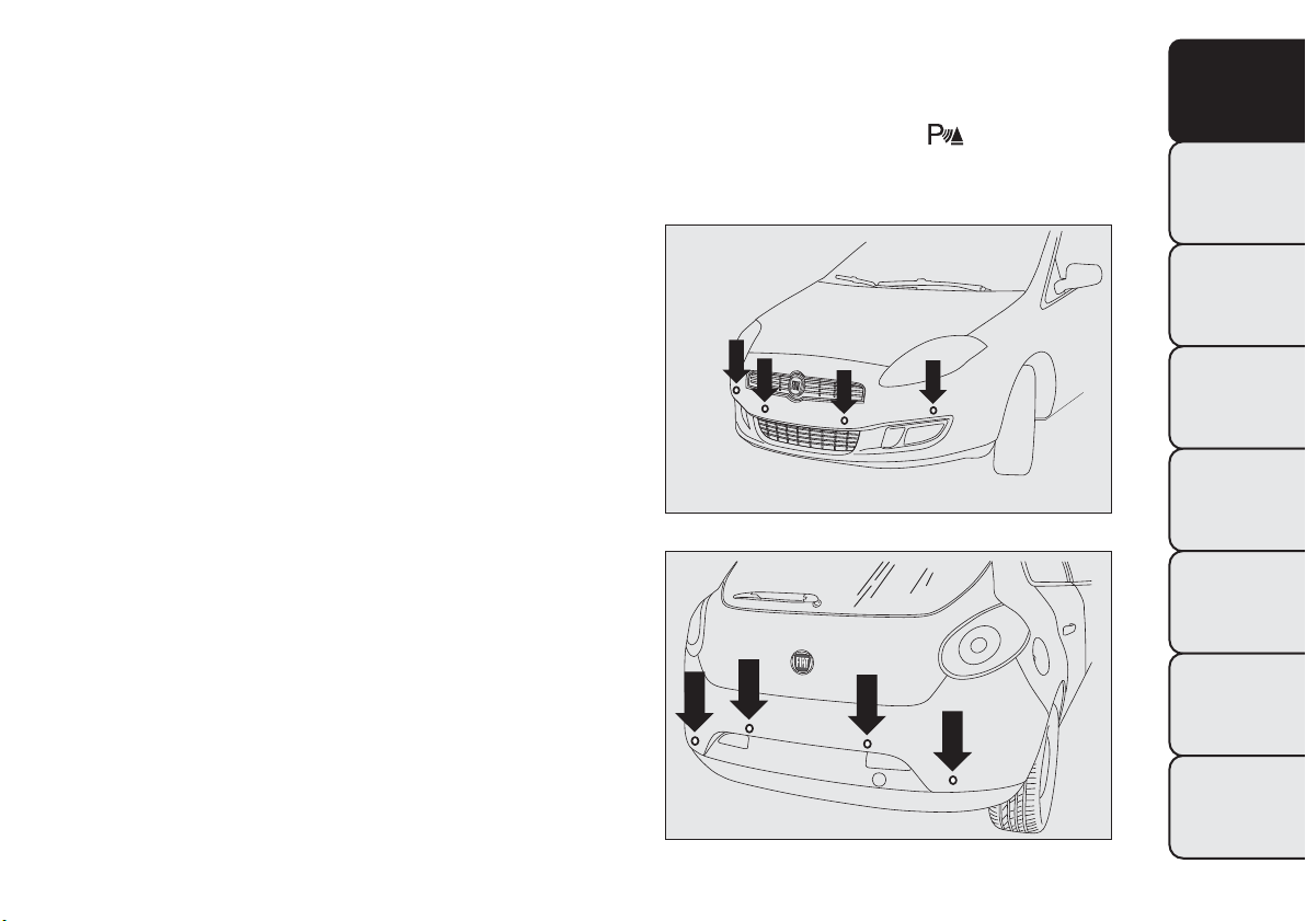
PARKING SENSORS
(for versions/markets, where provided)
Parking sensors provide the driver with information
on the distance when approaching obstacles behind
the vehicle (versions with 4 rear sensors) or in
front of and behind the vehicle (versions with 4 front
and 4 rear sensors).
The system therefore provides a further aid during
parking manoeuvres because it allows the
identification of obstacles outside of the driver's field
of vision.
The driver is notified of the presence and distance of
the obstacle from the vehicle by an acoustic signal
which varies depending on the distance from the
obstacle (as the distance from the obstacle decreases
the frequency of the acoustic signal increases).
SENSORS
In order to measure the distance of obstacles, the
system uses 4 sensors located in the front bumper
(for versions/markets, where provided) fig. 94 and
4 sensors located in the rear bumper fig. 95.
Version with 4 sensors
On the version with 4 rear sensors, the system is
activated automatically when the reverse gear is
engaged.
Version with 8 sensors
On the version with 4 front sensors and 4 rear
sensors, the system is activated when reverse gear is
engaged or by pressing button
fig. 96.
fig. 94
F0Q0745
fig. 95
F0Q0603
103
GETTING TO
KNOW YOUR CAR
SAFETY
STARTING AND
DRIVING
WARNING LIGHTS
AND MESSAGES
IN AN EMERGENCY
SERVICING AND
MAINTENANCE
TECHNICAL
SPECIFICATIONS
INDEX

When reverse gear is released, the front and rear
sensors remain activated until a speed of around 15
km/h is exceeded to allow the parking manoeuvre to
be completed.
The system can also be activated by pressing the
button
fig. 96 in the central panel: a warning light
in the button comes on when the system is
activated.
Every time the ignition key is turned to MAR-ON
the LED on the button
flashes briefly to indicate
that the system is running a diagnosis. The LED
activation should not be understood as a fault.
The sensors are deactivated by pressing the button
again
fig. 96 or when a speed of 15 km/h is
exceeded: the warning light in the button is off when
the system is not active.
When the sensors are activated, the system starts to
produce acoustic signals from the front or rear
buzzers as soon as an obstacle is detected with the
frequency increasing as the obstacle gets closer.
When the obstacle is less than about 30 cm away,
the sound becomes continuous. Depending on
the position of the obstacle (in front or behind) the
sound is produced by the corresponding buzzers
(front or rear). The obstacle closest to the vehicle is
signalled.
The acoustic signal stops immediately if the distance
of the obstacle increases. The sound cycle remains
constant if the distance measured by the centre
sensors remains unchanged, while if this situation
occurs for the side sensors, the signal is interrupted
after about 3 seconds (for example, to prevent
signals in the case of manoeuvres alongside walls).
WARNING
Parking and other dangerous
manoeuvres however are always the
driver’s responsibility.When making these
manoeuvres, always make sure that no people
(especially children) or animals are present
in your manoeuvring space.The parking sensors
are designed to assist drivers: in any case, you
must always pay the utmost attention during
potentially dangerous manoeuvres, even when
carried out at low speed.
fig. 96
F0Q0035
104
GETTING TO
KNOW YOUR CAR
SAFETY
STARTING AND
DRIVING
WARNING LIGHTS
AND MESSAGES
IN AN EMERGENCY
SERVICING AND
MAINTENANCE
TECHNICAL
SPECIFICATIONS
INDEX
ACOUSTIC SIGNAL
The information concerning the presence and
distance of an obstacle from the vehicle is
transmitted by means of acoustic signals from
buzzers installed in the passenger compartment:
❒ in the versions with 4 rear sensors, a buzzer in the
front dashboard area warns of the presence of rear
obstacles;
❒ in the versions with 8 sensors (4 front and 4 rear
sensors), a front buzzer warns of the presence of
obstacles at the front and a buzzer located at
the rear warns of the presence of obstacles at the
rear. This notifies the driver of the direction
(front/rear) of the obstacles.
When reverse gear is engaged an intermittent
acoustic signal is automatically activated.
The acoustic signal:
❒ increases as the distance between the car and the
obstacle decreases;
❒ becomes continuous when the distance between
the car and the obstacle is less than 30 cm and
stops immediately if the distance increases;
❒ remains constant if the distance remains
unchanged; if this situation concerns the side
sensors, the buzzer will stop after about 3 seconds
to avoid, for example, warning indications in the
event of manoeuvres along walls.
WARNING
For correct operation, sensors must
always be clean from mud, dirt, snow or
ice. Be careful not to scratch or damage the
sensors while cleaning them.Avoid using dry,
rough or hard cloths.The sensors should be
washed using clean water with the addition of
car shampoo if necessary. In washing stations,
clean sensors quickly keeping the vapour
jet/high pressure washing nozzles at 10 cm at
least from the sensors.
WARNING
Only have the bumpers repainted or any
retouches to the paintwork in the area
of the sensors carried out by a Fiat Dealership.
Incorrect paint application could affect t he
operation of the parking sensors.
105
GETTING TO
KNOW YOUR CAR
SAFETY
STARTING AND
DRIVING
WARNING LIGHTS
AND MESSAGES
IN AN EMERGENCY
SERVICING AND
MAINTENANCE
TECHNICAL
SPECIFICATIONS
INDEX
SENSOR OPERATING RANGE
The sensors allow the system to check the front part
(version with 8 sensors) and rear part of the vehicle.
Their position covers the middle and side areas of
the front and rear of the vehicle.
If an obstacle is located in a middle area, it is
detected when the distance is less than about 0.9 m
(front) and 1.40 m (rear).
If the obstacle is located at the side, it is detected at
distances of less than 0.6 m.
OPERATION WITH TRAILER
The operation of the sensors is automatically
deactivated when the trailer's electric cable plug is
inserted in the car's tow hook socket.
The sensors are automatically enabled again when
the trailer's cable plug is removed.
IMPORTANT If you wish to leave the tow hook
fitted when there is no trailer, it is advisable to
contact a Fiat Dealership to have the system updated
because the tow hook could be detected as an
obstacle by the central sensors.
FAILURE INDICATIONS
Any failures in the parking sensor system are
signalled, when reverse gear is engaged, by the
warning light
in the instrument panel lighting up
or by the symbol
together with a message in the
display (see "Warning lights and messages" chapter).
GENERAL WARNINGS
During parking manoeuvres, pay the utmost
attention to any obstacles that could be located
above or below the sensors.
Under certain circumstances close objects located in
front of or behind the car may not be detected and
could therefore cause damage to the car or be
damaged themselves.
The following conditions may influence the
performance of the parking sensor system:
❒ Reduced sensor sensitivity and a reduction in the
parking assistance system performance could be
due to the presence on the surface of the sensor
of: ice, snow, mud, thick paint.
❒ The sensors may detect a non-existent obstacle
(echo interference) due to mechanical
interference, for example when washing the car, in
rain (strong wind), hail.
❒ The signals sent by the sensors can also be altered
by the presence of ultrasonic systems (e.g.
pneumatic brake systems or pneumatic drills) near
the vehicle.
106
GETTING TO
KNOW YOUR CAR
SAFETY
STARTING AND
DRIVING
WARNING LIGHTS
AND MESSAGES
IN AN EMERGENCY
SERVICING AND
MAINTENANCE
TECHNICAL
SPECIFICATIONS
INDEX

❒ The performance of the parking assistance system
may also be affected by the position of the
sensors. For example, if the geometry is altered
(as a result of wear of the shock absorbers,
suspension), the tyres are changed, the vehicle is
too heavily laden or specific tuning is carried
out that lowers the vehicle.
❒ The detection of obstacles at the top part of the
car may not be guaranteed because the system
detects obstacles that could cause an impact with
the car in the bottom part.
AT THE FILLING STATION
MOTORI DIESEL - Operation at low
temperatures
If the outside temperature is very low, diesel
thickens due to the formation of paraffin clots with
consequent defective operation of the fuel supply
system.
In order to avoid these problems, different types of
diesel are distributed according to the season:
summer type, winter type and arctic type
(cold/mountain areas). If refuelling with diesel fuel
whose specifications are not suitable for the current
temperature, it is advisable to mix TUTELA DIESEL
ART additive in the proportions shown on the
container. Pour the additive into the tank before the
diesel fuel.
When using or parking the car for a long time in the
mountains or cold areas, it is advisable to refuel
using locally available diesel. In this case, it is also
advisable to keep the tank over 50% full.
107
GETTING TO
KNOW YOUR CAR
SAFETY
STARTING AND
DRIVING
WARNING LIGHTS
AND MESSAGES
IN AN EMERGENCY
SERVICING AND
MAINTENANCE
TECHNICAL
SPECIFICATIONS
INDEX
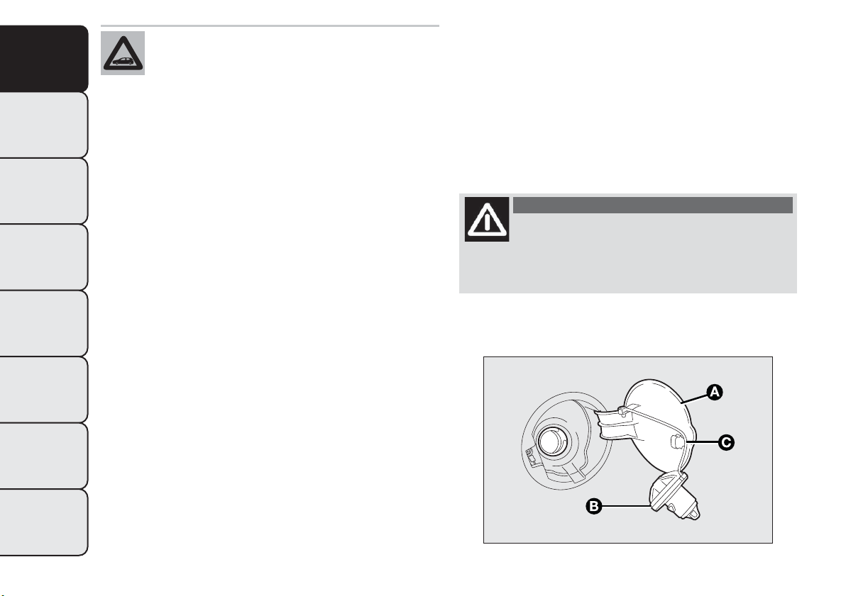
For diesel engines, only use diesel fuel for
motor vehicles in accordance with EN 590
European specifications.The use of other
products or mixtures may damage the engine
beyond repair and consequently invalidate the
warranty, due to the damage caused. If you
accidentally refuel with another type of fuel, do
not start the engine, and drain the tank. If the
engine has been run for even an extremely
limited amount of time, you must not only drain
the fuel tank, but the rest of the supply circuit
as well.
REFUELLING CAPACITY
To fill the tank completely, top-up twice after the
first click of the fuel delivery gun. Further top-ups
could cause faults in the fuel feeding system.
FUEL FILLER CAP
Opening fig. 97
Open flap A pulling it outwards, hold cap B still,
insert the ignition key in the lock and turn it
anticlockwise.
Turn the cap anticlockwise and remove it. The cap
has a device C that attaches it to the flap so it
cannot be lost. When refilling, attach the cap to the
flap, as shown.
Closing
Fit the cap (complete with key) and turn it clockwise
until it clicks once or more.
Turn the key clockwise and extract it, then close the
flap.
IMPORTANT The airtight sealing of the tank may
cause a slight vacuum. A suction noise when you
release the cap is therefore entirely normal.
WARNING
Do not bring naked flames or lit
cigarettes near to the fuel tank opening:
fire risk. Keep your face away from the fuel
filler to prevent breathing in harmful vapours.
fig. 97
F0Q0695
108
GETTING TO
KNOW YOUR CAR
SAFETY
STARTING AND
DRIVING
WARNING LIGHTS
AND MESSAGES
IN AN EMERGENCY
SERVICING AND
MAINTENANCE
TECHNICAL
SPECIFICATIONS
INDEX
PROTECTING THE ENVIRONMENT
The following devices are used for reducing diesel
fuel engine emissions:
❒ oxidising catalytic converter
❒ exhaust gas recirculation system (EGR)
❒ particulate filter (DPF).
WARNING
Under normal operating conditions, the
silencer becomes very hot.Therefore
do not park the car on flammable materials
(grass, dry leaves, pine needles, etc.): fire
hazard.
DIESEL PARTICULATE FILTER (DPF)
(for versions/markets, where provided)
The Diesel Particulate Filter is a mechanical filter,
integral with the exhaust system, that physically traps
particulates present in the exhaust gases of diesel
engines. The diesel particulate filter has been
adopted to eliminate almost all particulates in
compliance with current / future legal regulations.
During normal use of the vehicle, the engine control
unit records a set of data (e.g.: travel time, type of
route, temperatures, etc.) and it will then calculate
how much particulate has been trapped by the filter.
Since this filter physically traps particulate, it should
be regenerated (cleaned) at regular intervals by
burning the carbon particles. The regeneration
procedure is controlled automatically by the engine
management control unit according to the filter
conditions and vehicle use conditions. There may be
a limited increase in the engine speed during the
regeneration, a limited increase in fumes and high
temperatures at the exhaust. These are not faults;
they do not impair vehicle performance or damage
the environment.
Particulate filter clogged
If the warning light switches on on the instrument
panel (along with the message on the display) refer
to the "Warning lights and messages" chapter.
109
GETTING TO
KNOW YOUR CAR
SAFETY
STARTING AND
DRIVING
WARNING LIGHTS
AND MESSAGES
IN AN EMERGENCY
SERVICING AND
MAINTENANCE
TECHNICAL
SPECIFICATIONS
INDEX
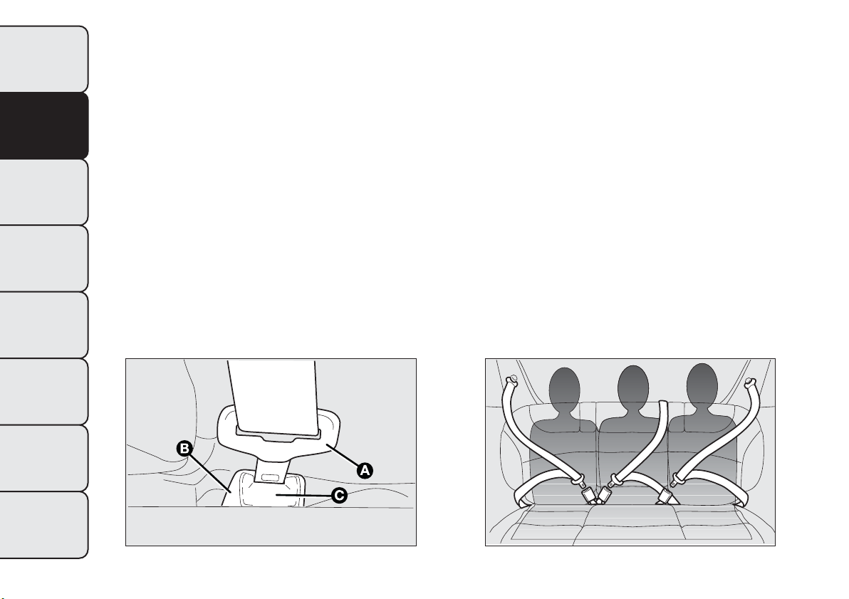
SAFETY
SEAT BELTS
USING THE SEAT BELTS
The seat belt should be worn keeping the torso
straight and rested against the backrest.
To fasten the seat belts, hold the tongue A fig. 98
and insert it into the buckle B, until it clicks into
place.
If the seat belt jams during removal, let it rewind for
a short stretch, then pull it out again without jerking.
To unfasten the seat belt, press button C. Guide
the seat belt with your hand while it is rewinding, to
prevent it from twisting.
Through the retractor, the seat belt automatically
adapts to the body of the occupant wearing it,
allowing freedom of movement.
The reel may lock when the car is parked on a steep
slope: this is perfectly normal. Furthermore, the
reel mechanism locks the belt if it is pulled sharply or
in the event of sudden braking, collisions and
high-speed bends.
The rear seat is fitted with inertia seat belts with
three anchor points and a reel for the side seats and
the middle one.
Wear the rear seat belts as shown in fig. 99.
fig. 98
F0Q0696
fig. 99
F0Q0267
110
GETTING TO KNOW
YOUR CAR
SAFETY
STARTING AND
DRIVING
WARNING LIGHTS
AND MESSAGES
IN AN EMERGENCY
SERVICING AND
MAINTENANCE
TECHNICAL
SPECIFICATIONS
INDEX
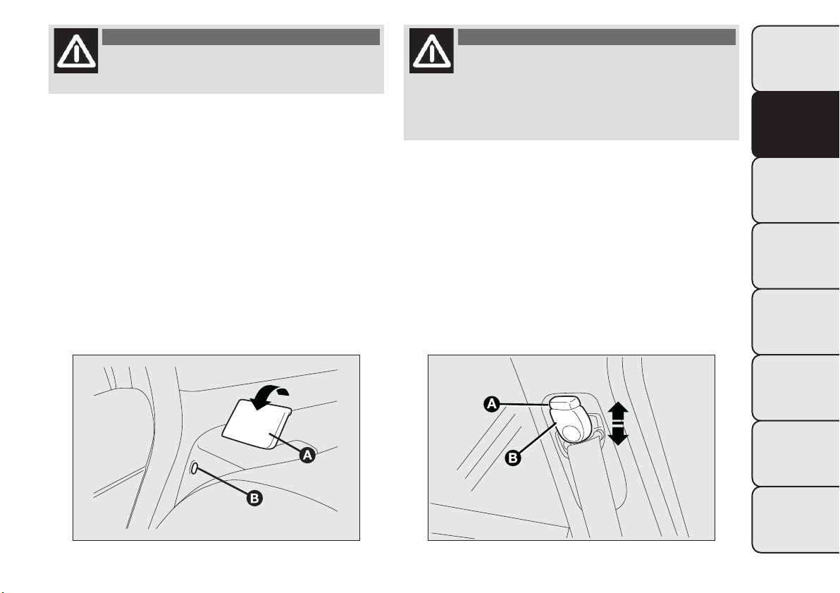
WARNING
Never press button C fig. 98 when
travelling.
IMPORTANT The backrest is correctly secured when
the red band B fig. 100 to the side of backrest
folding handle A disappears. This red band indicates
that the backrest is not secured.
IMPORTANT Remember that after a violent impact,
rear-seat passengers who are not wearing their
seat belts not only expose themselves to significant
risk of injury, but also represent a danger to
passengers occupying the front seats.
IMPORTANT When putting the rear seat back in its
normal position, make sure that the seat belts are
positioned so that they are ready to use.
WARNING
Make sure that the backrest is correctly
secured on both sides (red bands B
fig. 100 not visible) to prevent it from moving
forward in the event of sharp braking, causing
injuries to passengers.
ADJUSTING THE FRONT SEAT BELT
HEIGHT
(for versions/markets, where provided)
Four different adjustments in height are possible.
To adjust, press button A fig. 101 and raise or lower
handle B.
Always adjust the height of the seat belts to fit the
person wearing it: this precaution could greatly
reduce the risk of injury in the event of collision.
fig. 100
F0Q0683
fig. 101
F0Q0697
111
GETTING TO KNOW
YOUR CAR
SAFETY
STARTING AND
DRIVING
WARNING LIGHTS
AND MESSAGES
IN AN EMERGENCY
SERVICING AND
MAINTENANCE
TECHNICAL
SPECIFICATIONS
INDEX
Correct adjustment is obtained when the belt passes
approximately half way between the shoulder and
the neck.
WARNING
Make height adjustment of the seat
belts when the car is stationary.
WARNING
After adjustment, al ways check that the
cursor to which the ring is fastened is
locked in one of the preset posi tions.To do this,
with the button A fig. 101 released, exert a
further pressure to allow the anchor device to
catch if release did not take place at one of the
preset positions.
SBR SYSTEM
This system consists of a buzzer which, in
conjunction with the
warning light flashing on the
instrument panel (initially in fixed mode with
continuous acoustic signal and then in flashing mode
with intermittent acoustic signal), warns the driver
and front passenger that their seat belts have not
been fastened.
For long-term deactivation of the SBR system,
contact a Fiat Dealership. The SBR system can be
reactivated at any time through the Setup Menu only
(see the "Menu Items" paragraph in the "Knowing
your car" chapter).
112
GETTING TO KNOW
YOUR CAR
SAFETY
STARTING AND
DRIVING
WARNING LIGHTS
AND MESSAGES
IN AN EMERGENCY
SERVICING AND
MAINTENANCE
TECHNICAL
SPECIFICATIONS
INDEX

PRETENSIONERS
The car is equipped with front seat belts
pretensioners, that reduce slack in the belts in the
event of a severe frontal impact. This guarantees the
perfect adherence of the seat belts to the occupants'
bodies before the restraining action begins.
The retractors lock to indicate that the pretensioner
has intervened.
This car is also equipped with a second pretensioner
(in the kick plate area). Its activation is signalled by
the shortening of the metal cable.
A slight discharge of smoke may be produced during
the activation of the pretensioner which is not
harmful and does not involve any fire hazard.
IMPORTANT To obtain the highest degree of
protection from the action of the pretensioner, wear
the seat belt tight to the chest and pelvis.
The pretensioner does not require any maintenance
or lubrication: any changes to its original conditions
will invalidate its efficiency. If, due to unusual natural
events (floods, sea storms, etc.), the device has
been affected by water and mud, it must be replaced.
WARNING
The pretensioner may be used only
once. Contact a Fiat Dealer ship to have
it replaced after it has been deployed.
Operations which lead to impacts,
vibrations or localised heating (over 100°C
for a maximum of six hours) in the area
around the pretensioner may damage or deploy
it. Contact a Fiat Dealership should intervention
be necessary on these components.
LOAD LIMITERS
To increase passenger safety in an accident, the front
and rear (for versions/markets where provided)
seat belt reels contain a load limiter which controls
the force acting on the chest and shoulders during
the restraining action of the belts in the event of
a head-on collision.
113
GETTING TO KNOW
YOUR CAR
SAFETY
STARTING AND
DRIVING
WARNING LIGHTS
AND MESSAGES
IN AN EMERGENCY
SERVICING AND
MAINTENANCE
TECHNICAL
SPECIFICATIONS
INDEX
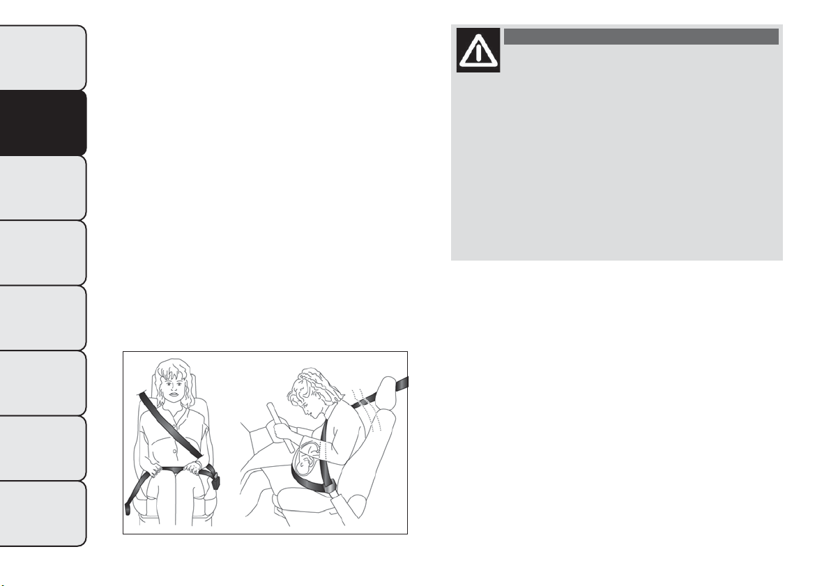
GENERAL INSTRUCTIONS FOR USING
THE SEAT BELTS
The driver must comply with (and have all car
passengers follow) any local regulations in force
concerning the use of seat belts. Always fasten the
seat belts before setting off.
Seat belts are also to be worn by pregnant women:
the risk of injury in the case of accident is greatly
reduced for them and the unborn child if they are
wearing a seat belt.
Pregnant women must position the lower part of the
belt very low down so that it passes over the pelvis
and under the abdomen (see fig. 102). The best
way to protect the unborn child is to protect the
mother. When a safety belt is worn properly, it
is more likely that the unborn child will not be hurt
in a crash. For pregnant women, as for anyone,
the key to making safety belts effective is wearing
them properly.
WARNING
For maximum safety, kee p the back of
your seat upright, lean back into it
and make sure the seat belt fits closely across
your chest and pelvis.Always fasten the seat
belts on both the front and the rear seats!
Travelling without wearing seat belts will
increase the r isk of serious injury or even death
in the event of an accident. Removing or
otherwise tampering with seat belt and
pretensioner components is strictly prohibited.
Any operations on these components must
be performed by qualified and authorised
technicians. Al ways go to a Fiat Dealership.
fig. 102
F0Q0885
114
GETTING TO KNOW
YOUR CAR
SAFETY
STARTING AND
DRIVING
WARNING LIGHTS
AND MESSAGES
IN AN EMERGENCY
SERVICING AND
MAINTENANCE
TECHNICAL
SPECIFICATIONS
INDEX
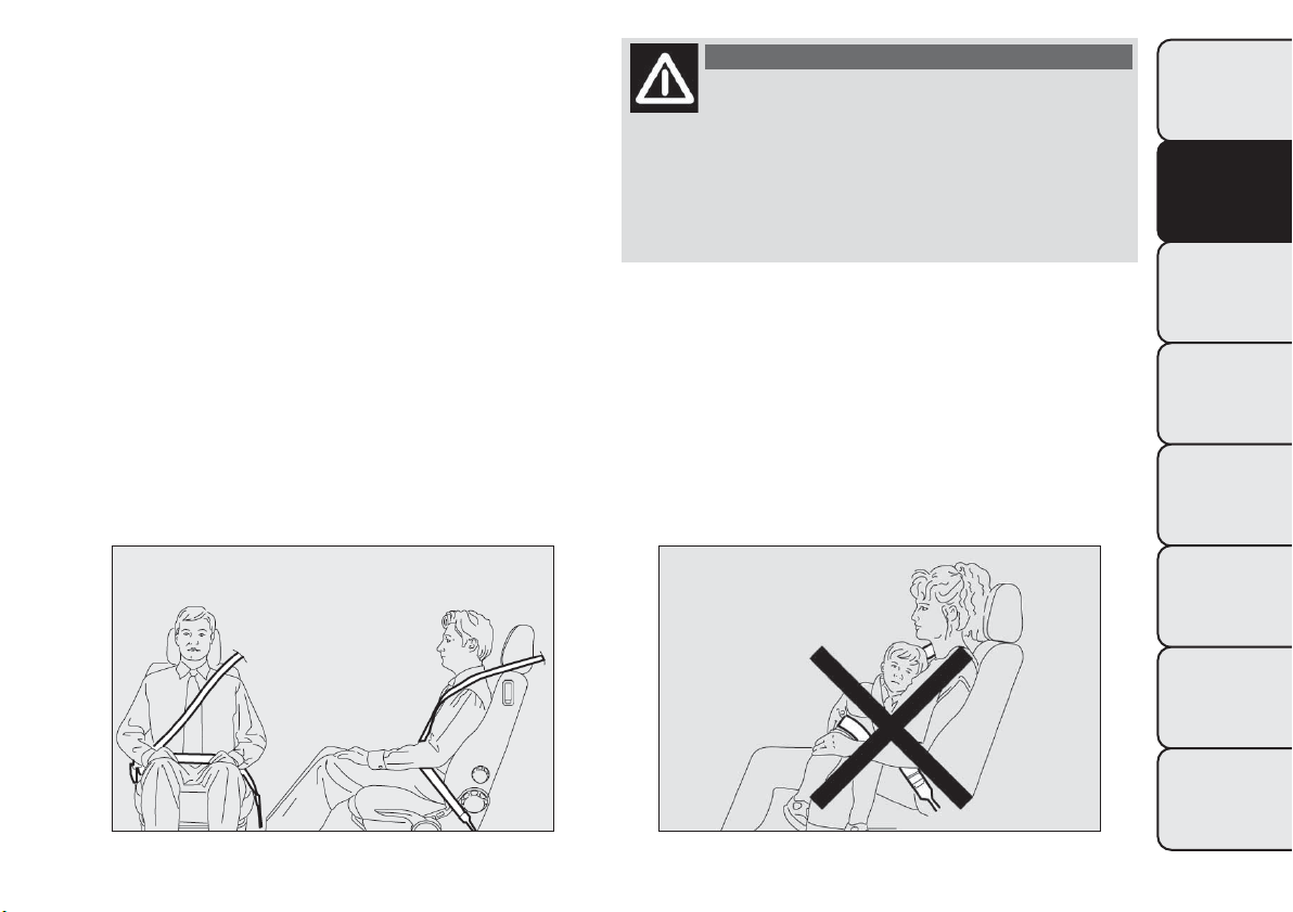
IMPORTANT The seat belt must not be twisted. The
upper part must pass over the shoulder and cross
the chest diagonally. The lower part must adhere to
the pelvis (as shown in fig. 103) rather than the
abdomen of the occupant. Never use devices (clips,
clamps, etc.) to hold the seat belt away from your
body.
IMPORTANT Each seat belt must be used by only
one person. Never travel with a child sitting on the
passenger's lap and a single belt to protect them
both fig. 104. In general, do not place any objects
between the person and the belt.
WARNING
If the belt has been subjected to a high
level of stress, for example after an
accident, it must be completely replaced
together with the attachments, attachment
fixing screws and the pretensioner. In fact, even
if the belt has no visible defects, it could have
lost its resilience.
fig. 103
F0Q0038
fig. 104
F0Q0039
115
GETTING TO KNOW
YOUR CAR
SAFETY
STARTING AND
DRIVING
WARNING LIGHTS
AND MESSAGES
IN AN EMERGENCY
SERVICING AND
MAINTENANCE
TECHNICAL
SPECIFICATIONS
INDEX

SEAT BELTS MAINTENANCE
Observe the following precautions for correct seat
belt maintenance:
❒ always use the seat belt with the strap well
stretched and not twisted; make sure that it is free
to run without obstructions;
❒ check seat belt operation as follows: attach the
seat belt and pull it hard;
❒ replace the belt after an accident of a certain
severity even if it does not appear to be damaged.
Always replace the seat belt if the pretensioners
were deployed;
❒ to clean the seat belts, wash by hand with water
and neutral soap, rinse and leave to dry in the
shade. Never use strong detergents, bleach, paints
or any other substance which could damage the
belt fibres;
❒ prevent the reels from getting wet: their correct
operation is only guaranteed if water does not
get inside;
❒ replace the seat belt when it shows wear or cuts.
CARRYING CHILDREN SAFELY
For optimal protection in the event of an impact, all
occupants must be seated and wearing adequate
restraint systems, including newborn and other
children!
This prescription is compulsory in all EC countries
according to EC Directive 2003/20/EC.
Compared with an adult, a child's head is larger and
heavier in proportion to his/her body and the child's
muscular and bone structures are not fully
developed. Therefore, correct restraint systems
other than adult seat belts are necessary to reduce
as much as possible the risk of injuries in the event
of an accident, braking or a sudden manoeuvre.
Children must be seated safely and comfortably. As
far as the characteristics of the child restraint
systems used allow, you are advised to keep children
in rear facing restraint systems for as long as possible
(at least until 3–4 years old), since this is the most
protected position in the event of an impact.
The choice of the most suitable child restraint device
depends on the weight of the child; there are
various types of child restraint systems and you are
advised always to choose the one that is most
suitable for the child.
116
GETTING TO KNOW
YOUR CAR
SAFETY
STARTING AND
DRIVING
WARNING LIGHTS
AND MESSAGES
IN AN EMERGENCY
SERVICING AND
MAINTENANCE
TECHNICAL
SPECIFICATIONS
INDEX
When over 1.50 m in height, from the point of view
of restraint systems, children are considered as
adults and wear seat belts normally.
In Europe the characteristics of children restraint
systems are ruled by the regulation ECE-R44, dividing
them into five weight groups:
Group Weight groups
Group 0 up to 10 kg of weight
Group 0+ up to 13 kg of weight
Group 1 9-18 kg in weight
Group 2 15-25 kg in weight
Group 3 22-36 kg of weight
All child restraint devices must bear the certification
data, together with the control mark, on a label
solidly fixed to the seat which must never be
removed.
Lineaccessori Fiat offers child restraint systems for
each weight group. These devices are recommended
having been specifically designed for Fiat cars.
WARNING
SEVERE DANGER.When an active
passenger airbag is fitted, DO NOT
install rear facing child restraint systems
on the front seat. Deployment of the
airbag in an accident could cause fatal injuries
to the child regardless of the severity of the
impact. It is advisable to always carry children
in a child restraint system on the rear seat,
which is the most protected position in the
event of a collision.
WARNING
On the sun visor there is a label with
suitable symbols reminding the user that
it is compulsory to deactivate the airbag if a
rear facing child restraint system is fitted.
Always comply with the instructions on the
passenger's side sun visor (see the "Front
airbag" paragraph).
WARNING
Do not move the front or rear seat if a
child is seated on it or on the dedicated
child restraint system.
117
GETTING TO KNOW
YOUR CAR
SAFETY
STARTING AND
DRIVING
WARNING LIGHTS
AND MESSAGES
IN AN EMERGENCY
SERVICING AND
MAINTENANCE
TECHNICAL
SPECIFICATIONS
INDEX
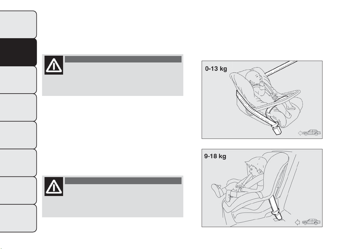
FITTING "UNIVERSAL"
CHILD RESTRAINT SYSTEM
(with seat belts)
GROUP 0 and 0+
WARNING
The diagram is indicative and for fitting
purposes only. Fit the child restraint
system according to the instructions, which must
be included.
Children up to 13 kg must be carried with rearward
facing restraint system of a type as shown in fig. 105
which, supporting the head, does not induce stress
on the neck in the event of sudden decelerations.
The rearward facing infant seat is restrained by the
car seat belts, as shown in fig. 105 and it must
restrain the child in turn with its own belts.
GROUP 1
WARNING
The diagram is indicative and for fitting
purposes only. Fit the child restraint
system according to the instructions, which must
be included.
Children of weight from 9 to 18 kg may be carried in
forward facing child restraint systems fig. 106.
fig. 105
F0Q0429
fig. 106
F0Q0772
118
GETTING TO KNOW
YOUR CAR
SAFETY
STARTING AND
DRIVING
WARNING LIGHTS
AND MESSAGES
IN AN EMERGENCY
SERVICING AND
MAINTENANCE
TECHNICAL
SPECIFICATIONS
INDEX
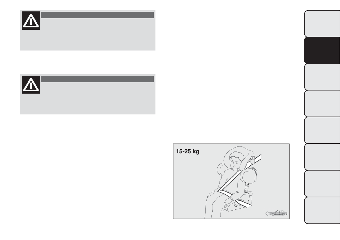
WARNING
Child restraint systems with Isofix
attachments are available for a safe
anchoring to the seat without using the car seat
belts.
GROUP 2
WARNING
The diagram is indicative and for fitting
purposes only. Fit the child restraint
system according to the instructions, which must
be included.
Children from 15 to 25 kg may use the car seat belts
directly fig. 107.
In this case, the child restraint system is used to
position the child correctly with respect to the seat
belts so that the diagonal belt section crosses the
child’s chest and not the neck, and the lower part is
snug on the pelvis not the abdomen.
fig. 107
F0Q0431
119
GETTING TO KNOW
YOUR CAR
SAFETY
STARTING AND
DRIVING
WARNING LIGHTS
AND MESSAGES
IN AN EMERGENCY
SERVICING AND
MAINTENANCE
TECHNICAL
SPECIFICATIONS
INDEX
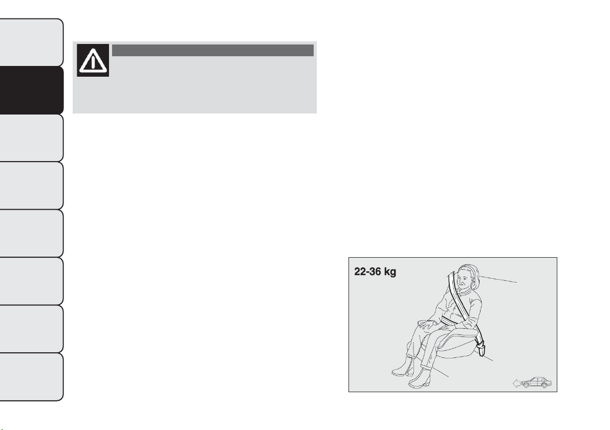
GROUP 3
WARNING
The diagram is indicative and for fitting
purposes only. Fit the child restraint
system according to the instructions, which must
be included.
For children between 22 kg and 36 kg, there are
dedicated restraint systems that allow the seat belt
to be worn correctly.
The fig. 108 shows the correct child positioning on
the rear seat.
Children over 1.50 m in height can wear seat belts
like adults.
fig. 108
F0Q0432
120
GETTING TO KNOW
YOUR CAR
SAFETY
STARTING AND
DRIVING
WARNING LIGHTS
AND MESSAGES
IN AN EMERGENCY
SERVICING AND
MAINTENANCE
TECHNICAL
SPECIFICATIONS
INDEX
SUITABILITY OF PASSENGER SEATS FOR UNIVERSAL RESTRAINT SYSTEM USE
According to the European Directive 2000/3/EC the suitability of each passenger seat position for the fixing
of universal child restraint systems is shown in the following table:
Group Weight range Front passenger Rear side passengers
Rear central
passenger
Group 0, 0+ up to 13 kg
UUU
Group 1 9–18 kg
UUU
Group 2 15–25 kg
UUU
Group 3 22–36 kg
UUU
U= suitable for child restraint systems in the "Universal" category, according to European Regulation EEC-R44 for the specified
"Groups".
121
GETTING TO KNOW
YOUR CAR
SAFETY
STARTING AND
DRIVING
WARNING LIGHTS
AND MESSAGES
IN AN EMERGENCY
SERVICING AND
MAINTENANCE
TECHNICAL
SPECIFICATIONS
INDEX
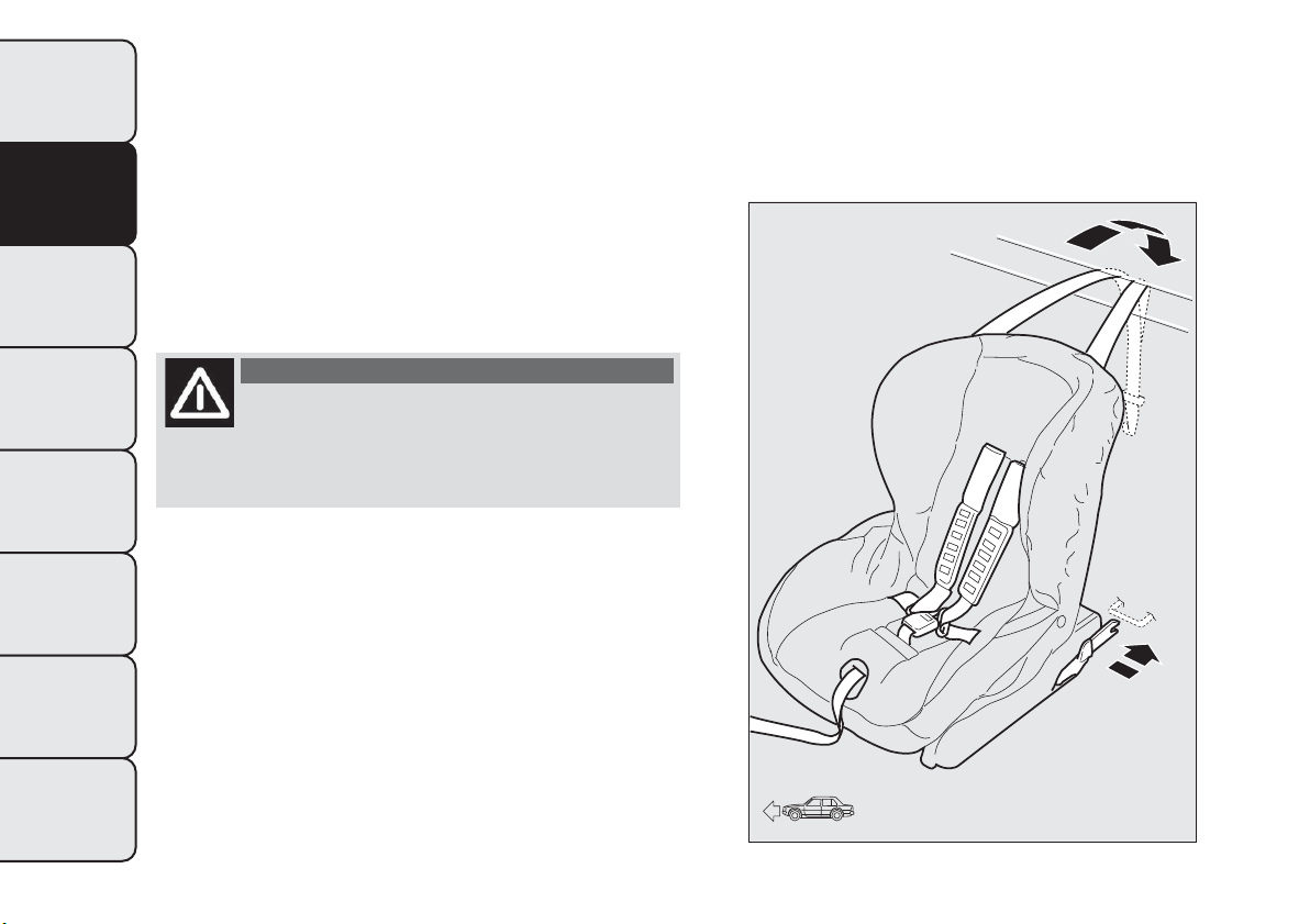
ISOFIX CHILD RESTRAINT SYSTEM
SETUP
The car is equipped with ISOFIX anchorages, a new
standard which makes fitting a child restraint system
quick, simple and safe.
Isofix systems can be fitted alongside conventional
child restraint systems on different seats in the same
car.
fig. 109An example of a Universal Isofix child
restraint system for weight group 1.
WARNING
The diagram is indicative and for fitting
purposes only. Fit the child restraint
system according to the instructions, which must
be included.
The other weight groups are covered by specific
Isofix child restraint systems, which can be used only
if specifically tested for this car (see list of cars
provided with the child restraint system).
fig. 109
F0Q0614
122
GETTING TO KNOW
YOUR CAR
SAFETY
STARTING AND
DRIVING
WARNING LIGHTS
AND MESSAGES
IN AN EMERGENCY
SERVICING AND
MAINTENANCE
TECHNICAL
SPECIFICATIONS
INDEX
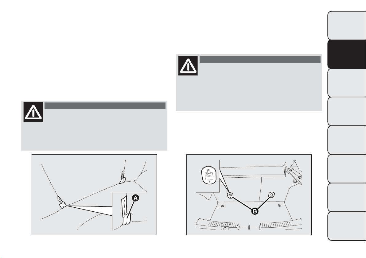
INSTALLING A UNIVERSAL ISOFIX CHILD
RESTRAINT SYSTEM
Attach the restraint system to the two metal
anchorages A fig. 110 located where the rear seat
cushion meets the backrest, then fix the upper strap
(available together with the restraint system) to
the dedicated anchorage B fig. 111 located at the
bottom behind the backrest.
Remember that when using a Universal Isofix child
restraint system, you can use approved child restraint
systems with the marking ECE R44/03 (R44/03 or
superior) “Universal Isofix”.
WARNING
If a Universal Isofix child seat is not
fixed to all three anchorages, the child
seat will not be able to protect the child
correctly. In a crash, the child could be seriously
or fatally injured.
The Universal Isofix “Duo Plus” child seat and the
special "G 0/1" seat are available from Lineaccessori
Fiat.
For any further details on installation/use, refer to
the instruction manual for the child seat.
WARNING
Fit the child seat when the car is
stationary.The child seat is correctly
anchored to the brackets when you hear the
click. Follow the instructions for assembly,
disassembly and positioning that the
manufacturer must supply with the child seat.
fig. 110
F0Q0698
fig. 111
F0Q0699
123
GETTING TO KNOW
YOUR CAR
SAFETY
STARTING AND
DRIVING
WARNING LIGHTS
AND MESSAGES
IN AN EMERGENCY
SERVICING AND
MAINTENANCE
TECHNICAL
SPECIFICATIONS
INDEX
SUITABILITY OF PASSENGER SEATS FOR ISOFIX CHILD RESTRAINT SYSTEM USE
The table below shows the various installation possibilities for Isofix child restraint systems on seats fitted
with Isofix attachments in accordance with European standard ECE 16.
Weight group
Child restraint system
position
Isofix size class Rear side passengers
Group 0 up to 10 kg Rear facing E
IL
Group 0+ up to 13 kg
Rear facing E
IL
Rear facing D
IL
Rear facing C
IL (*)
Group1from9upto18kg
Facing backwards D
IL
Facing backwards C
IL (*)
Forward facing B
IUF
Forward facing BI
IUF
Forward facing A
IUF
IL : suitable for ISOFIX child restraint systems of the categories for "specific vehicles", "restricted", or "semiuniversal", approved for
this type of vehicle.
(*)The Isofix child seat can be installed by moving the front seat all the way up.
IL Suitable for special child restraint systems. Isofix type suitable and tested for this type of car. The seat can be installed by moving
the front seat forward.
IUF: suitable for forward facing Isofix child restraint systems in the Universal category and type-approved for the use in the weight
group.
124
GETTING TO KNOW
YOUR CAR
SAFETY
STARTING AND
DRIVING
WARNING LIGHTS
AND MESSAGES
IN AN EMERGENCY
SERVICING AND
MAINTENANCE
TECHNICAL
SPECIFICATIONS
INDEX
WARNING
Fit the child restraint system according
to the instructions, which must be
included.
Main recommendations to carry children
safely:
❒ Install the child restraint systems on the rear seat,
which is the most protected position in the event
of an accident.
❒ Keep children in rear facing restraint systems for as
long as possible, until 3–4 years old if possible.
❒ Should a rear facing child restraint system be
installed on the rear seats, it is advisable to
position it as far forward as the position of the
front seat allows.
❒ If the passenger's front airbag is deactivated always
check the warning light on the instrument panel
to make sure that it has actually been deactivated.
❒ Carefully follow the child restraint manufacturer's
instruction supplied with the child restraint
system. Keep the instructions in the car along with
the other documents and this handbook. Do not
use second-hand child restraint systems without
instructions.
❒ Only one child is to be strapped into each
retaining system; never carry two children using
one child restraint system.
❒ Always check that the seat belts do not interfere
with the child's throat.
❒ Always check that the seat belt is well fastened by
pulling on it.
❒ While travelling, do not let the child sit incorrectly
or unfasten the belts.
❒ Never allow a child to put the belt's diagonal
section under an arm or behind their back.
❒ Never carry children on your lap, even newborns.
No-one can restrain a child in the event of an
accident.
❒ In the event of an accident, replace the child
restraint system with a new one.
125
GETTING TO KNOW
YOUR CAR
SAFETY
STARTING AND
DRIVING
WARNING LIGHTS
AND MESSAGES
IN AN EMERGENCY
SERVICING AND
MAINTENANCE
TECHNICAL
SPECIFICATIONS
INDEX

FRONT AIRBAGS
The car is fitted with front airbags for the driver and
the passenger, and with a knee bag on the driver's
side (for versions/markets, where provided).
The front driver/passenger airbags and the driver's
knee bag (for versions/markets, where provided)
have been designed to protect the front seat
occupants in the event of frontal impacts of
medium/high severity, by placing the bag between the
occupant and the steering wheel or dashboard.
Therefore non-deployment in other types of impacts
(side impacts, rear shunts, roll-overs, etc.) does not
indicate a system malfunction.
In the event of a frontal impact, an electronic control
unit triggers the inflation of the bags if required.
The cushions immediately inflate, placing themselves
between the front occupants' bodies and structures
that could cause injuries. Immediately after, the
cushions deflate.
The front driver/passenger airbags and the driver's
knee bag (for versions/markets, where provided) are
not a replacement for, but rather complement the
use of, seat belts, which should always be worn,
as specified by law in Europe and most non-European
countries.
In the event of an impact, those not wearing a seat
belt will move forward and come into contact with
the bag which is still inflating. The protection offered
by the bag is compromised in these circumstances.
Front airbags may not be activated in the following
situations:
❒ frontal impacts against highly deformable objects
not involving the front surface of the car (e.g.
wing collision against guard rail, etc.);
❒ car wedging under other vehicles or protective
barriers (e.g. trucks or guard rails);
Failure to activate in the conditions described above
is due to the fact that they may not provide any
additional protection compared with seat belts, so
their activation would be inappropriate.
In these cases, non-deployment does not indicate a
system malfunction.
WARNING
Do not apply s tickers or other objects
on the steering wheel, on the dashboard
in the passenger side airbag area, on side
upholstery on the roof or on the seats. Never
put objects (e.g. mobile phones) on the
passenger's side dashboard since they could
interfere with correct inflation of the airbag
and also cause serious injury to the passengers.
126
GETTING TO KNOW
YOUR CAR
SAFETY
STARTING AND
DRIVING
WARNING LIGHTS
AND MESSAGES
IN AN EMERGENCY
SERVICING AND
MAINTENANCE
TECHNICAL
SPECIFICATIONS
INDEX
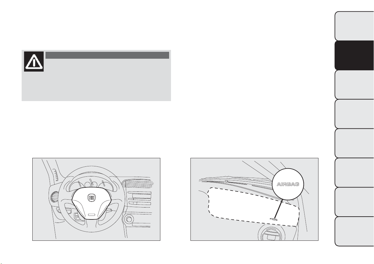
FRONT AIRBAG DRIVER'S SIDE
This consists of an instantly inflating bag contained in
a special compartment in the centre of the steering
wheel fig. 112.
WARNING
Always drive with both hands on the
steering wheel so that, if the airbags
must be deployed, they may do so freely. Do not
drive with your body bent forward. Keep your
back straight against the backrest.
FRONT AIRBAG PASSENGER'S SIDE
This consists of an instantly inflating bag contained in
a special recess in the dashboard: this bag has a
larger volume than that of the driver fig. 113.
The front driver and passenger airbags are designed
and calibrated to best protect front-seat passengers
wearing seat belts.
The volume of the front airbags at max. inflation fills
most of the space between the steering wheel and
the driver and between the dashboard and the
passenger.
fig. 112
F0Q0624
fig. 113
F0Q0700
127
GETTING TO KNOW
YOUR CAR
SAFETY
STARTING AND
DRIVING
WARNING LIGHTS
AND MESSAGES
IN AN EMERGENCY
SERVICING AND
MAINTENANCE
TECHNICAL
SPECIFICATIONS
INDEX
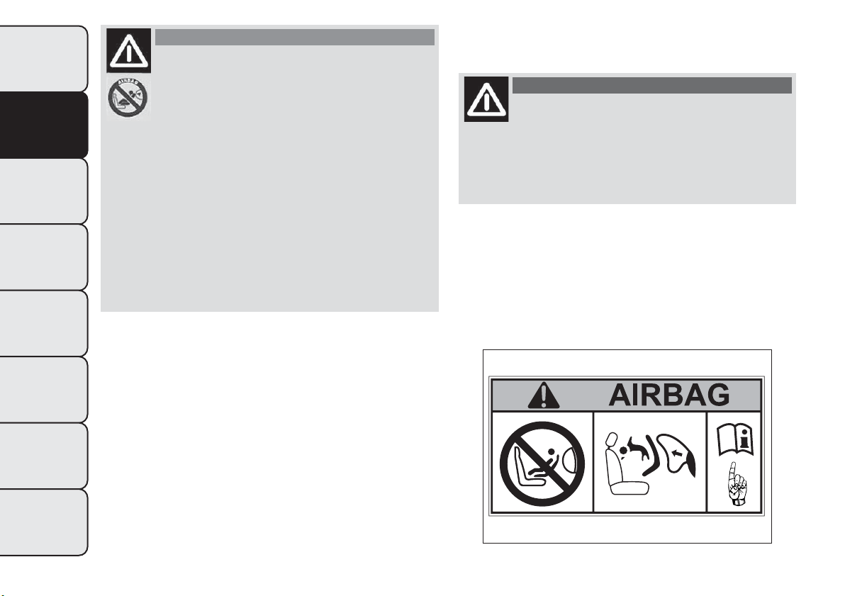
WARNING
SEVERE DANGERWhen an active
passenger airbag is fitted, DO NOT
install rearward facing child restraint
systems on the front seat. Deployment
of the airbag in an accident could cause fatal
injuries to the child regardless of the severity of
the impact.Therefore, always deactivate the
passenger airbag when a rearward facing child
restraint sys tem is installed on the front
passenger seat.The front passenger seat must
also be positioned back as far as possible in
order to avoid the child restraint system from
coming into contact with the dashboard.
Immediately reactivate t he passenger air bag as
soon as the child restraint system has been
removed.
FRONT PASSENGER AIRBAG AND CHILD
RESTRAINT SYSTEMS
WARNING
When an active passenger airbag is
fitted, DO NOT install rear facing child
restraint sys tems on the front seat. Deployment
of the airbag in an accident could cause fatal
injuries to the child regardless of the severity of
the impact.
ALWAYS comply with the instructions on the label
stuck on the passenger side sun visor fig. 114.
fig. 114
F0Q0920
128
GETTING TO KNOW
YOUR CAR
SAFETY
STARTING AND
DRIVING
WARNING LIGHTS
AND MESSAGES
IN AN EMERGENCY
SERVICING AND
MAINTENANCE
TECHNICAL
SPECIFICATIONS
INDEX
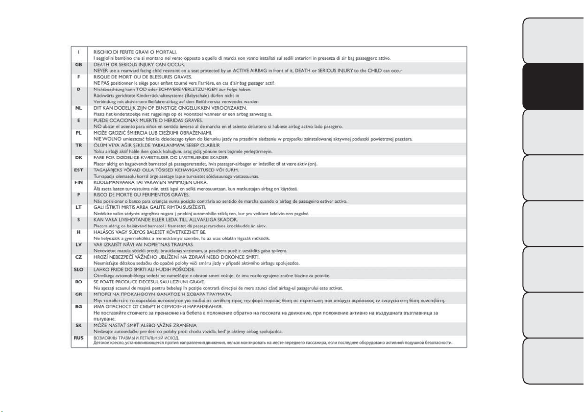
FRONT PASSENGER AIRBAG AND CHILD RESTRAINT SYSTEMS:WARNING
fig. 115
F0Q0921
129
GETTING TO KNOW
YOUR CAR
SAFETY
STARTING AND
DRIVING
WARNING LIGHTS
AND MESSAGES
IN AN EMERGENCY
SERVICING AND
MAINTENANCE
TECHNICAL
SPECIFICATIONS
INDEX
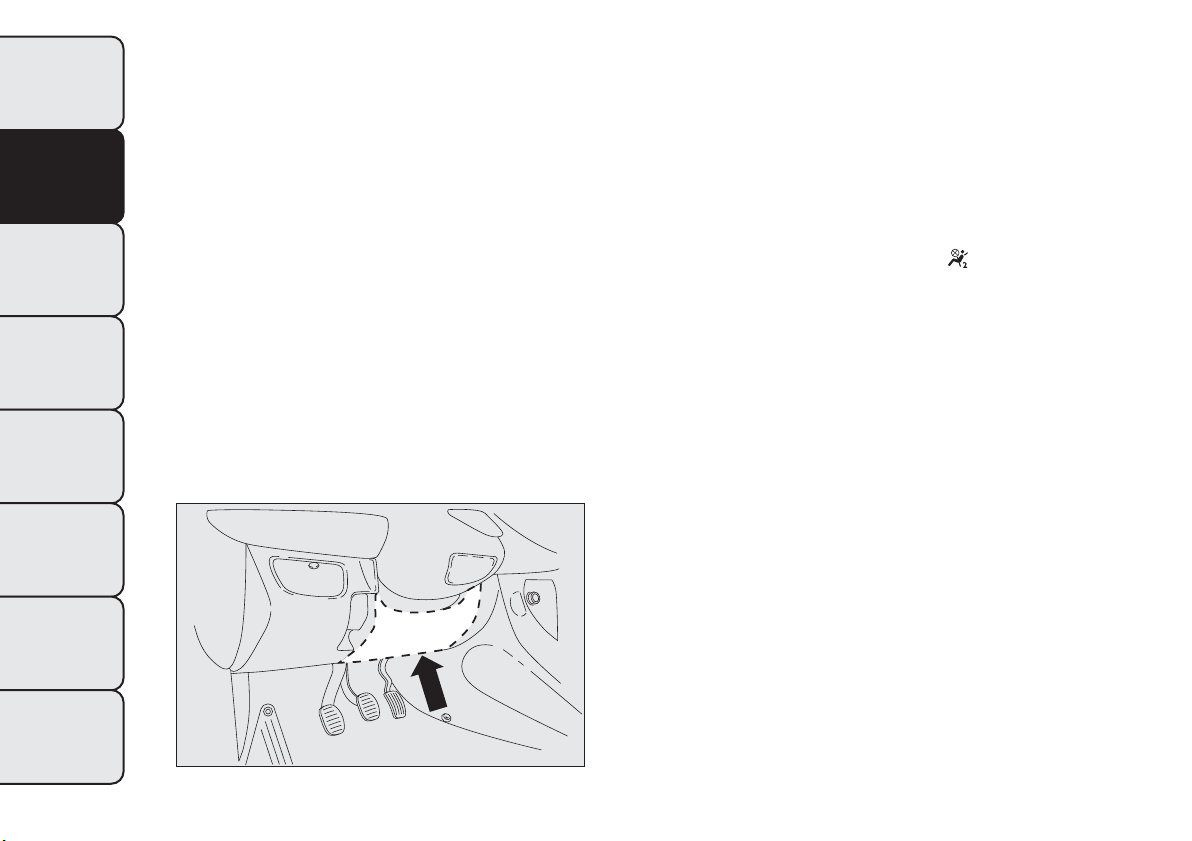
DRIVER SIDE KNEE BAG
(for versions/markets, where provided)
It is located in a special compartment under the
dashboard and is protected by a dedicated cover
fig. 116. It provides protection to the lower limbs in
the event of frontal impact .
Deactivation of passenger side airbags: front
airbag and side bag for pelvis-chest-shoulder
protection (for versions/markets, where
provided)
If a child must be carried on the front seat in
backward-facing child restraint system, deactivate the
passenger side front airbag and front side bag for
pelvis, chest and shoulder protection (for
versions/markets, where provided).
With the airbags deactivated, the
warning light
switches on in the instrument panel.
IMPORTANT To deactivate the airbags see the
description in the "Knowing your car" chapter, "Menu
Options" paragraph.
A
U
TO
fig. 116
F0Q0702
130
GETTING TO KNOW
YOUR CAR
SAFETY
STARTING AND
DRIVING
WARNING LIGHTS
AND MESSAGES
IN AN EMERGENCY
SERVICING AND
MAINTENANCE
TECHNICAL
SPECIFICATIONS
INDEX
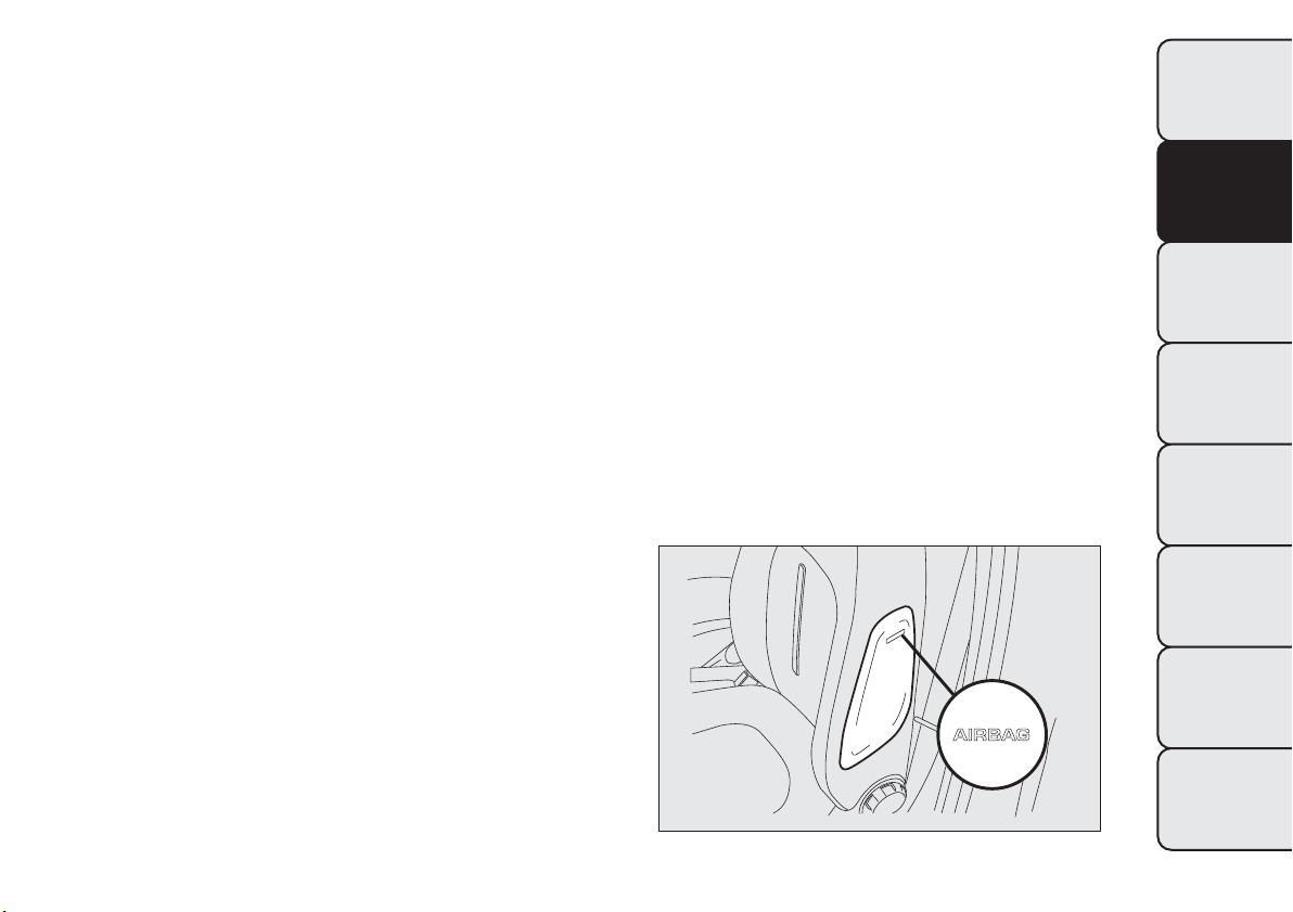
SIDE AIRBAGS
(Side bag - Window bag)
The car is fitted with front side bags for driver and
passenger, protecting the chest/pelvis, and window
bags for protecting front and rear passengers’ heads.
Side airbags protect occupants from side impacts
of medium/high severity by placing the bag between
the occupant and the internal parts of the side
structure of the car.
Non-activation of side bags in other types of
collisions (frontal impacts, rear shunts, roll-overs,
etc...) is not an indication of system malfunction.
In the event of a side impact, an electronic control
unit triggers the inflation of the bag if required.
The cushion immediately inflates, placing itself
between the occupant's body and structures that
could cause injuries. Immediately after, the cushion
deflates.
Side bags are not a replacement of, but rather a
complement to, seat belts, which you are
recommended to wear at all times, as specified by
law in Europe and most non-European countries.
SIDE BAGS
(for versions/markets, where provided)
These comprise two types of bags located in the
front seat backrests fig. 117 which protect the pelvis,
chest and shoulder area of the occupants in the
event of a side impact of medium/high severity.
fig. 117
F0Q0701
131
GETTING TO KNOW
YOUR CAR
SAFETY
STARTING AND
DRIVING
WARNING LIGHTS
AND MESSAGES
IN AN EMERGENCY
SERVICING AND
MAINTENANCE
TECHNICAL
SPECIFICATIONS
INDEX
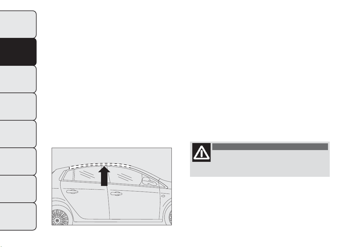
WINDOW BAG
(for versions/markets, where provided)
This comprises a "curtain" bag housed behind the
roof side linings and covered by special trims fig. 118.
It is designed to protect the head of front and rear
occupants in the event of a side collision, thanks
to the wide cushion inflation surface.
The deployment of side bags in the event of side
impacts of low severity is not required.
In the event of a side impact, the system provides
best protection if the passenger sits on the seat in a
correct position, thus allowing correct window
bag deployment.
For this reason, the seat belt must be worn at all
times. In the case of side impacts, the seat belts hold
occupants in the correct position and prevent them
from being thrown out of the car by a very violent
collision.
Therefore, front side bags (for versions/markets,
where provided) are not a replacement of, but
complementary to, seat belts, which you are
recommended to always wear, as specified by law in
Europe and most non-European countries.
IMPORTANT Do not affix rigid objects to the
garment hooks or support handles.
IMPORTANT Do not rest your head, arms or elbows
on the door, on the windows and on the window
bag area to avoid injuries during inflation.
IMPORTANT Never lean your head, arms or elbows
out of the window.
IMPORTANT In the event of a side impact, the
system provides best protection if the passenger sits
on the seat in a correct position, thus allowing
correct window bag deployment.
WARNING
Do not cover the backrest of the front
seats with covers which are not sui table
for use with side bags.
fig. 118
F0Q0703
132
GETTING TO KNOW
YOUR CAR
SAFETY
STARTING AND
DRIVING
WARNING LIGHTS
AND MESSAGES
IN AN EMERGENCY
SERVICING AND
MAINTENANCE
TECHNICAL
SPECIFICATIONS
INDEX
IMPORTANT
Do not wash the seats with water or pressurised
steam (wash by hand or at automatic seat washing
stations).
The front airbags and/or front side bags (for
versions/markets, where provided) may be deployed
if the car is subject to heavy collisions or accidents
involving the underbody area, such as for example
violent shocks against steps, kerbs or low obstacles,
car falling into big holes or sags in the road.
When the airbag deploys it emits a small amount of
dust: the dust is harmless and does not indicate
the beginning of a fire. The dust may irritate the skin
and eyes however: in this case, wash with neutral
soap and water.
Airbag checking, repair and replacement must be
carried out at a Fiat Dealership.
If the car is scrapped, have the airbag system
deactivated at a Fiat Dealership.
Pretensioners and airbags are deployed according to
different logics on the basis of the type of collision.
Failure to deploy of one or more of the devices does
not indicate a system malfunction.
WARNING
If the
warning light does not switch
on when the key is turned to MAR-ON,
or stays on while driving (on some versions
together with a message on the display) there
may be a fault in the restraint systems. In this
case, the airbags or the pretensioners may
not be activated in the case of an accident or
(in a lesser number of cases) they may be
activated incorrectly. Contact your Fiat
Dealership immediately to have this system
checked.
WARNING
On cars with side bags, do not cover the
front seat backrests with extra covers.
WARNING
Do not travel carrying objects in your
lap, in front of your chest or between
your lips (pipe, pencils, etc.): they could cause
severe injury if the airbag is deployed in an
accident.
133
GETTING TO KNOW
YOUR CAR
SAFETY
STARTING AND
DRIVING
WARNING LIGHTS
AND MESSAGES
IN AN EMERGENCY
SERVICING AND
MAINTENANCE
TECHNICAL
SPECIFICATIONS
INDEX
WARNING
If the car has been stolen or in the case
of attempt to steal it, if i t has been
subjected to vandalism or floods, have the
airbag system checked by a Fiat Dealership.
WARNING
When the ignition key is inserted and
turned to MAR-ON, airbags may be
deployed if another car crashes into the vehicle,
even if the engine is not running and the car is
stationary.Therefore, even if the car is
stationary, when an active passenger airbag is
fitted, DO NOT install rearward facing child
restraint systems on the front passenger seat.
Deployment of the airbag following an impact
could cause fatal injuries to the child.Therefore,
always deactivate the passenger airbag when
a rearward facing child restraint system is
installed on the front passenger seat.The front
passenger seat must also be positioned back
as far as possible in order to avoid the child
restraint sys tem from coming into contact with
the dashboard. Immediately reactivate the
passenger airbag as soon as the child restraint
system has been removed.Also remember that,
if the key is turned to STOP, none of the safety
devices (airbags or pretensioners) will be
deployed in the event of collision. Non-
deployment in such cases does not indicate a
system malfunction.
WARNING
When the ignition key is turned to
MAR-ON, the warning light
(with
passenger's front airbag activated) turns on and
flashes for a few seconds to remind you that
the passenger's airbag will be deployed in a
crash, after which it should go off.
WARNING
The front airbag is designed to be
deployed for impacts of a greater
intensity than for the pretensioners. For impacts
whose intensity falls between the two
activation levels , it is normal for only the
pretensioners to be activated.
WARNING
The airbag does not replace seat belts
but increases their efficiency.
Furthermore, since front airbags are not
deployed in low-speed frontal impacts, side
impacts, rear shunts or roll-overs, the
passenger s are protected only by the seat belts
which must therefore be fastened at all times.
134
GETTING TO KNOW
YOUR CAR
SAFETY
STARTING AND
DRIVING
WARNING LIGHTS
AND MESSAGES
IN AN EMERGENCY
SERVICING AND
MAINTENANCE
TECHNICAL
SPECIFICATIONS
INDEX
STARTING AND DRIVING
STARTING THE ENGINE
The car is fitted with an electronic engine lock
device: if the engine fails to start, see the paragraph
“The Fiat CODE system” in the section “Knowing
your car”.
Engine starting is guaranteed to -18°C (Italy and
central Europe) and -20°C (Northern Europe).
We recommend that during the initial
period you do not demand to full
performance from the car (e.g. excessive
acceleration, long journeys at top speed, sharp
braking etc.).
When the engine is switched off never
leave the key turned to MAR to prevent
useless current absorption from draining
the battery.
WARNING
It is dangerous to have the engine
running indoors.The engine consumes
oxygen and engine exhaust contains carbon
dioxide, carbon monoxide and other toxic
gasses.
WARNING
Remember that the brake servo and
power steering are not operational until
the engine has been started, therefore much
effort than usual is required on t he brake pedal
and steering wheel.
STARTING PROCEDURE FOR DIESEL
VERSIONS
Proceed as follows:
❒ engage the handbrake and place the gear lever in
neutral;
❒ turn the ignition key to MAR: the warning lights
and on the instrument panel will turn on;
❒ wait for the warning lights
and to switch
off;
❒ press the clutch pedal down to the floor without
touching the accelerator;
❒ turn the ignition key to AVV as soon as warning
light
switches off. Waiting too long will waste
the heating work carried out by the glow plugs.
Release the key as soon as the engine starts.
IMPORTANT With cold engine, the accelerator must
be entirely released when turning the ignition key
to position AVV.
135
GETTING TO KNOW
YOUR CAR
SAFETY
STARTING AND
DRIVING
WARNING LIGHTS
AND MESSAGES
IN AN EMERGENCY
SERVICING AND
MAINTENANCE
TECHNICAL
SPECIFICATIONS
INDEX
If the engine does not start at the first attempt,
return the ignition key to STOP before attempting to
start again.
If, when the ignition key is at MAR-ON the
warning light remains lit, turn the key to STOP
and then back to MAR-ON. If the warning light
remains lit, try with the other keys provided with the
car.
If you still cannot start the engine, contact a Fiat
Dealership.
Warning light will flash for 60 seconds
after starting or during prolonged
cranking to indicate a fault with the glow
plug heating system.You can use the car as usual
if the engine starts but you should contact a
Fiat Dealership as soon as possible.
When the engine is switched off never
leave the key turned to MAR to prevent
useless current absorption from draining
the battery.
HOW TO WARM UP THE ENGINE AFTER IT
HAS JUST STARTED
Proceed as follows:
❒ Drive off slowly, letting the engine turn at medium
revs. Do not accelerate abruptly;
❒ Do not demand full performance at first. Wait
until the engine coolant temperature gauge starts
moving.
Never jump start the engine by pushing,
towing or coasting downhill.This could
cause fuel to flow into the catalytic
converter and damage it beyond repair.
EMERGENCY START-UP
Contact a Fiat Dealership if instrument panel
warning light
(or the symbol on the display) stays
on constantly.
STOPPING THE ENGINE
Turn the ignition key to STOP while the engine is
idling.
IMPORTANT After a taxing drive, you should allow
the engine to “catch its breath” before turning it
off by letting it idle to allow the temperature in the
engine compartment to fall.
A quick burst on the accelerator before
stopping the engine serves no practical
purpose; it wastes fuel and is especially
damaging to turbocharged engines.
136
GETTING TO KNOW
YOUR CAR
SAFETY
STARTING AND
DRIVING
WARNING LIGHTS
AND MESSAGES
IN AN EMERGENCY
SERVICING AND
MAINTENANCE
TECHNICAL
SPECIFICATIONS
INDEX
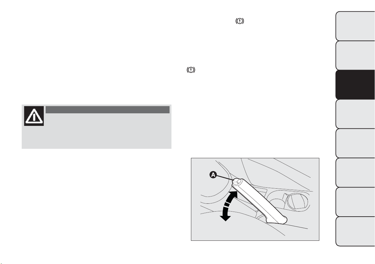
PARKING
Proceed as follows:
❒ stop the engine and engage the handbrake;
❒ engage a gear (on a slope, engage first gear if the
car is facing uphill or reverse if it is facing
downhill) and leave the wheels steered.
Block the wheels with a wedge or a stone if the car
is parked on a steep slope.
Do not leave the key in the ignition switch to
prevent the battery from running down.
WARNING
Never leave children unattended in the
car.Always remove the key from the
ignition when leaving the car and take it with
you.
HANDBRAKE
The handbrake is located between the front seats.
To use the handbrake pull the lever upwards until the
car cannot be moved.
Four or five clicks are generally enough when the car
is on level ground while nine or ten may be required
if the car is on a steep slope and laden.
IMPORTANT If this is not the case, contact a Fiat
Dealership for adjustment.
When the handbrake is engaged and the ignition key
is at MAR-ON, the
warning light will switch on
in the instrument panel.
Proceed as follows to release the handbrake:
❒ slightly lift the handbrake and press release button
A fig. 119;
❒ keep button A pressed and lower the lever. The
warning light in the instrument panel will
switch off.
Press the brake pedal when carrying out this
operation to prevent the car from moving
accidentally.
IMPORTANT For cars equipped with a front
armrest, lift this up to ensure that it does not
interfere with the action of the handbrake.
fig. 119
F0Q0628
137
GETTING TO KNOW
YOUR CAR
SAFETY
STARTING AND
DRIVING
WARNING LIGHTS
AND MESSAGES
IN AN EMERGENCY
SERVICING AND
MAINTENANCE
TECHNICAL
SPECIFICATIONS
INDEX
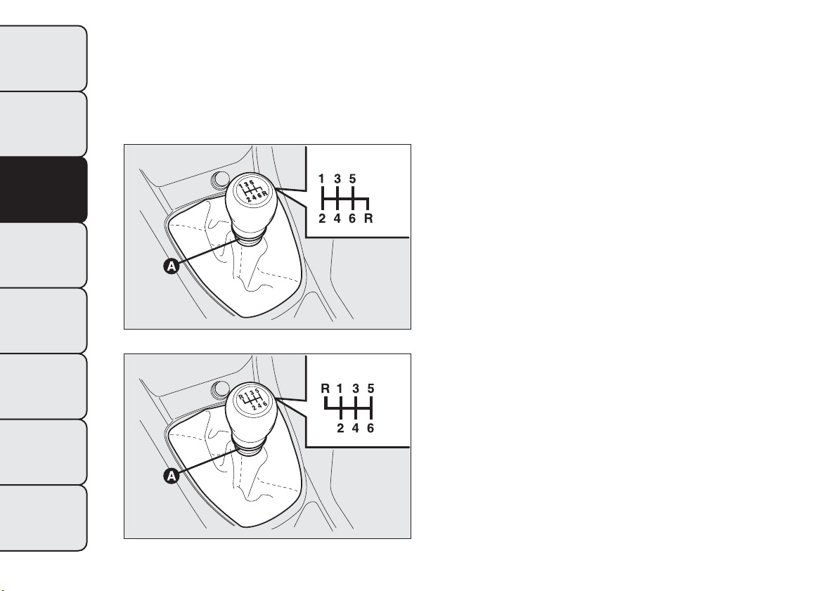
USING THE GEARBOX
To engage the gears, press the clutch pedal fully and
shift the gear lever into one of the required positions
(the diagram for gear engagement is shown on the
knob fig. 120 fig. 121).
To engage 6
th
gear, operate the lever by pressing it
towards the right in order to avoid engaging 4
th
gear
by mistake. The same applies to the shift from 6
th
to 5
th
gear.
To engage reverse R from neutral, lift sliding ring A
and, at the same time:
❒ move the lever to the right and then backwards
(1.6 MultiJet versions) fig. 120;
or
❒ move the lever to the left and then forwards (2.0
MultiJet versions - for versions/markets, where
provided) fig. 121.
IMPORTANT Reverse can only be engaged when the
car is completely stationary. With the engine
running, wait for at least 2 seconds with the clutch
pedal fully pressed before engaging reverse to
prevent damage to the gears and grating.
IMPORTANT The clutch pedal should be used only
for gear changes. Do not drive with your foot resting
on the clutch pedal, however lightly. For versions/
markets where provided, the electronic clutch pedal
control could cut in, interpreting the incorrect
driving style as a fault.
fig. 120 - 1.6 MultiJet versions
F0Q0734
fig. 121 - 2.0 MultiJet versions (where provided)
F0Q0783
138
GETTING TO KNOW
YOUR CAR
SAFETY
STARTING AND
DRIVING
WARNING LIGHTS
AND MESSAGES
IN AN EMERGENCY
SERVICING AND
MAINTENANCE
TECHNICAL
SPECIFICATIONS
INDEX
WARNING
Depress the clutch pedal fully to change
gear correctly. It is therefore essential
that there is nothing under the pedals: make
sure the mats are lying flat and do not get
in the way of the pedals.
Do not drive wit h your hand resting on
the gear lever as the force exerted, even if
slight, could lead over time to premature
wear of the gearbox internal components.
SAVING FUEL
Some useful tips are given below for fuel saving and
reducing harmful emissions of CO
2
and other
pollutants [nitrogen oxides, unburnt hydrocarbons,
Particulate Matter (PM) etc.].
GENERAL CONSIDERATIONS
The general factors that affect fuel consumption are
listed below.
Car maintenance
Have checks and adjustments carried out in
accordance with the “Scheduled Servicing Plan”.
Ty r e s
Check the tyre pressures at least once every four
weeks: if the pressure is too low, consumption levels
increase as resistance to rolling is higher.
Unnecessary loads
Do not travel with an overloaded boot. The weight
of the car (especially when driving in town) and
its ride greatly affects consumption and stability.
Roof rack/ski rack
Remove the roof rack or the ski rack from the roof
after use. These accessories lower aerodynamic
penetration and adversely affect consumption levels.
When transporting particularly large objects, use a
trailer if possible.
139
GETTING TO KNOW
YOUR CAR
SAFETY
STARTING AND
DRIVING
WARNING LIGHTS
AND MESSAGES
IN AN EMERGENCY
SERVICING AND
MAINTENANCE
TECHNICAL
SPECIFICATIONS
INDEX

Electric devices
Use electrical devices only for the amount of time
necessary. The heated rear window, additional
headlights, windscreen/rear window wipers and
heater fan need a considerable amount of energy,
therefore increasing fuel consumption (by up to 25%
in the urban cycle).
Climate control system
Air conditioning leads to higher fuel consumption (on
average up to +20%). If the temperature outside
permits, try and use the air vents.
Spoilers
The use of non-certified spoilers may adversely affect
air drag and fuel consumption.
DRIVING STYLE
The main driving styles that affect fuel consumption
are listed below.
Starting
Do not warm the engine with the car at a standstill
or at idle or high speed: under these conditions
the engine warms up much more slowly, increasing
electrical consumption and emissions. It is therefore
advisable to move off immediately, slowly, avoiding
high speeds: in this way the engine will warm faster.
Unnecessary actions
Avoid accelerating when starting at traffic lights or
before switching off the engine. This and also double
declutching is absolutely pointless on modern cars
and also increases consumption and pollution.
Gear selection
As soon as the conditions of the traffic and road
allow, use a higher gear. Using a low gear for faster
acceleration will increase consumption.
In the same way improper use of a high gear
increases consumption, emissions an engine wear.
Max. speed
Fuel consumption increases considerably with speed.
Maintain a constant speed, avoiding unnecessary
braking and acceleration, which cost in terms of both
fuel consumption and emissions.
140
GETTING TO KNOW
YOUR CAR
SAFETY
STARTING AND
DRIVING
WARNING LIGHTS
AND MESSAGES
IN AN EMERGENCY
SERVICING AND
MAINTENANCE
TECHNICAL
SPECIFICATIONS
INDEX

Acceleration
Accelerating violently severely affects consumption
and emissions: acceleration should be gradual and
should not exceed the maximum torque.
USAGE CONDITIONS
The main usage conditions that negatively affect fuel
consumption are listed below.
Cold starting
Short journeys and frequent cold starts do not allow
the engine to reach optimum operating temperature.
This results in a significant increase in consumption
levels (from +15 to +30% on the urban cycle) and
emissions.
Traffic and road conditions
Rather high consumption levels are linked to
situations with heavy traffic, for instance when
travelling in queues with frequent use of the lower
gears or in cities with many traffic lights. Winding
mountain roads and rough road surfaces also
adversely affect consumption.
Traffic hold-ups
During prolonged hold-ups (e.g. level crossings) the
engine should be switched off.
TOWING TRAILERS
IMPORTANT NOTES
For towing caravans or trailers the car must be fitted
with a certified tow hook and an adequate electric
system. Installation should be carried out by
specialised personnel who will issue the required
papers for travelling on roads.
Install any specific and/or additional rear view mirrors
as specified by the Highway Code.
Remember that when towing a trailer, steep hills are
harder to climb, braking distances increase and
overtaking takes longer depending on the overall
weight.
Engage a low gear when driving downhill, rather than
constantly using the brake.
The weight the trailer exerts on the car tow hook
reduces the car's loading capacity by the same
amount. To make sure that the maximum towable
weight is not exceeded (given in the car registration
document) account should be taken of the fully
laden trailer, including accessories and luggage.
Respect the speed limits specific to each country for
vehicles towing trailers.
In any case, the maximum speed must not exceed 80
km/h.
141
GETTING TO KNOW
YOUR CAR
SAFETY
STARTING AND
DRIVING
WARNING LIGHTS
AND MESSAGES
IN AN EMERGENCY
SERVICING AND
MAINTENANCE
TECHNICAL
SPECIFICATIONS
INDEX
WARNING
The ABS with which the car may be
equipped will not control the braking
system of the trailer. Particular caution is
required on slippery roads.
WARNING
Never modify the braking system of the
car to control the trailer brake.The
trailer braking system must be fully
independent of the car’s hydraulic system.
INSTALLING THETOW HOOK
The towing device should be fastened to the
bodywork by specialised personnel according to any
additional and/or integrative information supplied
by the Manufacturer of the device. The towing device
must meet current regulations with reference to
Directive 94/20/EEC and subsequent amendments.
For any version the towing device used must be right
for the towable weight of the car on which it is to
be installed.
IMPORTANT The use of auxiliary loads other than
external lights (electric brake, winch, etc.) must
be used with engine running.
For the electric connection a unified connector
should be used, which is generally placed on a special
bracket fastened to the towing device, and a special
ECU should be installed on the car to control the
trailer's exterior lights.
7 or 13-pole 12 V DC connections should be used
(CUNA/UNI and ISO/DIN Standards). Follow any
instructions provided by the car manufacturer and/or
the towing device manufacturer.
An electric brake or winch should be powered
directly by the battery through a cable with a
cross-section of no less than 2.5 mm
2
.
IMPORTANT Electric brakes or other devices must
be used with engine running.
In addition to the electrical branches, the vehicle's
electrical system can be connected only to the supply
cable for an electric brake and to the cable for an
internal trailer light, though not more than 15 W. For
connections use the preset control unit with battery
cable no less than 2.5 mm
2
.
142
GETTING TO KNOW
YOUR CAR
SAFETY
STARTING AND
DRIVING
WARNING LIGHTS
AND MESSAGES
IN AN EMERGENCY
SERVICING AND
MAINTENANCE
TECHNICAL
SPECIFICATIONS
INDEX
SNOW TYRES
Use snow tyres of the same size as the normal tyres
provided with the car.
A Fiat Dealership will be happy to provide advice
concerning the most suitable type of tyre for the
customer's requirements.
For the type of tyre to be used, inflation pressures
and the specifications of snow tyres, follow the
instructions given in paragraph "Wheels" in section
"Technical specifications".
The winter features of these tyres are reduced
considerably when the tread depth is below 4 mm.
Replace them in this case.
Due to snow tyre features, under normal conditions
of use or on long motorway journeys, the
performance of these tyres is much lower than that
of standard tyres. Their usage should therefore be
restricted in accordance with their type approval.
IMPORTANT When using snow tyres with a
maximum speed index below the one that can be
reached by the car (increased by 5%), place a notice
in the passenger compartment, plainly in view, which
states the maximum speed allowed by the snow
tyres (as per EC Directive).
All four tyres should be the same (brand and track)
to ensure greater safety when driving and braking
and better driveability.
Remember that you should not change the rotation
direction of the tyres.
WARNING
The maximum speed for snow tyres
marked “Q” is 160 km/h, while it is 190
km/h for “T” tyres and 210 km/h for "H" tyres.
You should, however, always stick to the speed
limits of the Road Traffic Code.
143
GETTING TO KNOW
YOUR CAR
SAFETY
STARTING AND
DRIVING
WARNING LIGHTS
AND MESSAGES
IN AN EMERGENCY
SERVICING AND
MAINTENANCE
TECHNICAL
SPECIFICATIONS
INDEX
SNOW CHAINS
The use of snow chains should be in compliance with
local regulations.
Snow chains may be fitted to the tyres of the front
wheels (drive wheels) only.
Check the tension of the snow chains after the first
few metres have been driven.
Use reduced size snow chains:
❒ for 205/55 R16" tyres, use reduced size snow
chains with a maximum projection of 9 mm
beyond the tyre profile;
❒ for 225/45 R17" tyres, use reduced size snow
chains with a maximum projection of 7 mm
beyond the tyre profile.
IMPORTANT 225/40 R18 92V tyres cannot be fitted
with chains. Snow chains may cause interference
with the surrounding elements.
IMPORTANT Snow chains cannot be fitted to the
space-saver wheel. If a front tyre is punctured,
replace a rear wheel with the space-saver wheel and
move the rear wheel to the front axle. In this way,
with two normal drive wheels at the front, snow
chains can be fitted.
Keep your speed down when snow chains
are fitted; do not exceed 50 km/h.Avoid
potholes, steps and pavements and avoid
driving for long distances on roads not covered
with snow to prevent damaging the car and
the roadbed.
144
GETTING TO KNOW
YOUR CAR
SAFETY
STARTING AND
DRIVING
WARNING LIGHTS
AND MESSAGES
IN AN EMERGENCY
SERVICING AND
MAINTENANCE
TECHNICAL
SPECIFICATIONS
INDEX

CAR INACTIVITY
If the car is to be left inactive for longer than a
month, the following precautions should be
observed:
❒ park the car in covered, dry and if possible
well-ventilated premises and slightly open
the windows;
❒ engage a gear and disengage the handbrake;
❒ disconnect the negative battery terminal and check
charge (see paragraph “Battery - Charge and
electrolyte level check” in chapter “Maintenance
and care”);
❒ clean and protect the painted parts using
protective wax;
❒ clean and protect the shiny metal parts using
special compounds available commercially;
❒ sprinkle talcum powder on the rubber windscreen
and rear window wiper blades and lift them off the
glass;
❒ cover the car with a cloth or perforated plastic
sheet. Do not use sheets of non-perforated plastic
as they do not allow moisture on the car body
to evaporate;
❒ inflate tyres to +0.5 bar above the standard
specified pressure and check it at intervals;
❒ do not drain the engine cooling system.
IMPORTANT Where relevant, switch off the car
alarm with the remote control.
145
GETTING TO KNOW
YOUR CAR
SAFETY
STARTING AND
DRIVING
WARNING LIGHTS
AND MESSAGES
IN AN EMERGENCY
SERVICING AND
MAINTENANCE
TECHNICAL
SPECIFICATIONS
INDEX
WARNING LIGHTS AND MESSAGES
WARNING LIGHTS AND MESSAGES
GENERAL WARNINGS
Warning lights are accompanied by a specific message
and/or acoustic warning where provided by the
control panel. These indications are concise and
precautionary and, as such, must not be
considered as exhaustive and/or an alternative to the
information contained in this Owner Handbook,
which you are advised to read carefully in all cases. In
the event of a failure indication, always refer to
the contents of this chapter.
IMPORTANT Failure indications displayed are divided
into two categories: very serious and less serious
failures.
Very serious failures are indicated by a repeated
and prolonged warning "cycle".
Less serious failures are indicated by a shorter
warning "cycle".
The display cycle of both failure types can be stopped
by pressing the MODE button. The warning light
(or symbol in the display) will remain on until the
cause of the malfunction is eliminated.
BRAKE FLUID LOW (red) /
HANDBRAKE ENGAGED (red)
Turning the key to the MAR-ON position the
warning light switches on, but it should switch off
after a few seconds.
LOW BRAKE FLUID LEVEL
The warning light switches on when the level of the
brake fluid in the reservoir falls below the minimum
level due to a possible leak in the circuit. On some
versions the display shows the dedicated message.
WARNING
If the
warning light switches on while
driving, stop immediately and contact
a Fiat Dealership.
HANDBRAKE APPLIED
The warning light turns on when the handbrake is
applied. If the car is moving the buzzer will also
sound.
146
GETTING TO KNOW
YOUR CAR
SAFETY
STARTING AND
DRIVING
WARNING LIGHTS
AND MESSAGES
IN AN EMERGENCY
SERVICING AND
MAINTENANCE
TECHNICAL
SPECIFICATIONS
INDEX
IMPORTANT If the warning light comes on when the
car is in motion, check that the handbrake is not
on.
BRAKE PAD WEAR (amber)
The warning light switches on if the front brake pads
are worn. In this case replace them as soon as
possible.
The display will show the dedicated message.
IMPORTANT Because the car is equipped with a
wear detection system only for the front brake pads,
when these are replaced the rear brake pads should
also be checked for wear.
AIRBAG FAILURE (red)
Turning the key to the MAR-ON position the
warning light switches on, but it should switch off
after a few seconds. The warning light stays on
constantly if there is a failure in the airbag system.
WARNING
If when turning the key to MAR-ON the
warning light
does not turn on or
stays on whilst driving, a failure may have
occurred in the restraint systems. In this case
the airbags or pretensioners may not be
deployed in an impact or, in a lower number of
cases, they may be deployed accidentally.
Contact a Fiat Dealer ship immediately to have
the system checked.
WARNING
Afaultwiththe
warning light is
indicated by flashing of the
warning
light, which signals the deactivation of the
passenger side front airbag. In addition, the
airbag system automatically disables the
airbags on the passenger's side (both front and
side airbags for versions/markets, where
provided). In this case, the warning light
may
not indicate a fault in the restraint systems.
Before continuing, contact a Fiat Dealership
immediately to have the system checked.
147
GETTING TO KNOW
YOUR CAR
SAFETY
STARTING AND
DRIVING
WARNING LIGHTS
AND MESSAGES
IN AN EMERGENCY
SERVICING AND
MAINTENANCE
TECHNICAL
SPECIFICATIONS
INDEX
PASSENGER/SIDE AIRBAGS
DEACTIVATED (amber)
The warning light
switches on when the front
passenger's airbag and side bag are disabled. With
front passenger airbag on, when the ignition key
is turned to MAR-ON, the
warning light switches
on constantly for several seconds, it flashes for
another few seconds and then it should switch off.
WARNING
A failure of the
warning light is
indicated by warning light
switching
on. In addition, t he airbag system automatically
disables the airbags on the passenger's side
(both front and side airbags where provided).
Before continuing, contact a Fiat Dealership
immediately to have the system checked.
UNFASTENED SEAT BELTS (red)
The warning light switches on constantly with the
car stationary and the driver's side or passenger side
seat belt (when the passenger is present) not
fastened.
The warning light will flash and a buzzer will sound if
the car is in motion and the front seat belts are
not correctly fastened.
The SBR (Seat Belt Reminder) system buzzer can
only be permanently switched off by a Fiat
Dealership.
The system can be reactivated using the Setup Menu.
LOW BATTERY CHARGE (red)
The warning light comes on when the ignition key is
turned to MAR-ON, but it should go out as soon
as the engine has started (with the engine running at
idle speed a brief delay before going out is
acceptable).
If the warning light stays on constantly or continues
to flash, contact a Fiat Dealership immediately.
CONTINUOUSLY ON: LOW
ENGINE OIL PRESSURE (red)
ON FLASHING: ENGINE OIL
DETERIORATED
(only MultiJet versions with DPF - red)
When the ignition key is turned to MAR-ON, the
warning light switches on but should switch off
as soon as the engine is started.
148
GETTING TO KNOW
YOUR CAR
SAFETY
STARTING AND
DRIVING
WARNING LIGHTS
AND MESSAGES
IN AN EMERGENCY
SERVICING AND
MAINTENANCE
TECHNICAL
SPECIFICATIONS
INDEX
Low engine oil pressure
The warning light switches on constantly together
(for versions/markets, where provided) with a
message on the display when the system detects that
the engine oil pressure is too low.
WARNING
If the warning light
turns on when
the car is travelling (on certain versions
together with the message on the display) stop
the engine immediately and contact a Fiat
Dealership.
Engine oil degraded
(versions with DPF only)
The warning light will flash and a specific message will
appear on the display (for versions/markets, where
provided). The warning light may flash in the
following ways, depending on the version:
❒ for 1 minute every two hours;
❒ cycles of 3 minutes with intervals with the warning
light off for 5 seconds until the oil is changed.
After the first indication, at each engine start-up the
warning light will continue flashing as described
above until the oil is changed. The display (for
versions/markets, where provided), shows a
dedicated message together with the warning light.
The flashing of this warning light should not be
considered as a fault; it informs the customer that
the oil needs to be changed following normal car use.
Note that engine oil degrades faster under the
following circumstances:
❒ mainly town use of the car which makes the DPF
regeneration process more frequent;
❒ use of the car for short drives, in which the engine
does not have time to reach its regular operating
temperature;
❒ repeated interruption of the regeneration process,
signalled by the DPF warning light coming on.
WARNING
If the warning light switches on, the
deteriorated engine oil must be changed
as soon as possible , and never more than 500
km from the first time that the warning light
switches on. Failure to observe the above
indication may result in severe damage to the
engine and invalidate the warranty. Remember
that the operation of this warning light is not
related to the amount of oil in the engine.
Therefore, never top up with oil when the
warning light starts flashing.
149
GETTING TO KNOW
YOUR CAR
SAFETY
STARTING AND
DRIVING
WARNING LIGHTS
AND MESSAGES
IN AN EMERGENCY
SERVICING AND
MAINTENANCE
TECHNICAL
SPECIFICATIONS
INDEX
“DUALDRIVE” ELECTRIC POWER
STEERING FAILURE (red)
The warning light comes on when the ignition key is
turned to MAR-ON, but it should switch off after
a few seconds.
The electric power steering system will not work
when the warning light is on and considerably more
effort is needed on the steering wheel. The car
can still be steered. In this case, contact a Fiat
Dealership.
The display will show the dedicated message.
“DUALDRIVE” ELECTRIC POWER
STEERING ACTIVATION (indication
on display)
The indication CITY switches on when the
"Dualdrive" electric power steering system is
activated by pressing the
button on the dashboard.
The indication CITY will switch off when the
button is pressed again.
EXCESSIVE ENGINE COOLANT
TEMPERATURE (red)
Turning the key to the MAR-ON position the
warning light switches on, but it should switch off
after a few seconds. The warning light turns on when
the engine is overheated. If the warning light comes
on, proceed as follows:
❒ when driving normally: stop the car, switch off
the engine and check that the water level in the
reservoir is not below the MIN mark. If it is, wait
for the engine to cool down, then slowly and
carefully open the cap, top up with coolant and
check that the level is between the MIN and MAX
marks on the reservoir. Also check visually for
any fluid leaks. If, when restarting, the warning
light switches on again, contact a Fiat Dealership.
❒ If the car is used under demanding
conditions (e.g. towing trailers uphill or fully
loaded): slow down and, if the light stays on, stop
the car. Wait for 2 or 3 minutes with the engine
running and slightly accelerated to further favour
the coolant circulation. Then stop the engine.
Check the correct coolant level as described
above.
IMPORTANT Over demanding routes, it is advisable
to keep the engine on and slightly accelerated for
a few minutes before switching it off.
The display will show the dedicated message.
150
GETTING TO KNOW
YOUR CAR
SAFETY
STARTING AND
DRIVING
WARNING LIGHTS
AND MESSAGES
IN AN EMERGENCY
SERVICING AND
MAINTENANCE
TECHNICAL
SPECIFICATIONS
INDEX
INCOMPLETE DOOR LOCKING
(red)
The warning light switches on when one or more
doors are not completely shut. An acoustic signal is
activated with the doors open and the car moving.
GENERIC FAILURE INDICATION
(amber)
Fuel cut-off inertia switch tripped
The warning light comes on when the inertial fuel
cut-off switch is triggered. The display shows the
dedicated message.
Engine oil pressure sensor failure
The warning light comes on when the engine oil
pressure sensor is faulty.
Dusk sensor failure
This warning light comes on when a dusk sensor
fault is detected. The display shows the dedicated
message.
Preset speed limit exceeded
(for Arab countries only)
The warning light switches on when the vehicle
speed exceeds 120 km/h.
Rain sensor failure
The warning light switches on when a rain sensor
fault is detected. The display shows the dedicated
message.
Parking sensor failure
(for versions/markets, where provided)
The warning light turns on when failure is detected in
the parking sensors.
Tyre pressure monitoring system failure
(for versions/markets, where provided)
The warning light turns on when a failure is detected
in the TPMS (for versions/markets where provided).
Should one or more wheels without a sensor be
fitted, the instrument panel warning light will come
on and stay on until the initial conditions are
restored. The display shows the dedicated message.
Note If one of the above mentioned failures occurs,
contact a Fiat Dealership as soon as possible.
151
GETTING TO KNOW
YOUR CAR
SAFETY
STARTING AND
DRIVING
WARNING LIGHTS
AND MESSAGES
IN AN EMERGENCY
SERVICING AND
MAINTENANCE
TECHNICAL
SPECIFICATIONS
INDEX
DPF (DIESEL PARTICULATE
FILTER) CLEANING IN PROGRESS
(only versions with DPF) (amber)
When the key is turned to MAR-ON, the warning
light switches on but should switch off after a few
seconds. The warning light (together with a message
and a symbol on the display on some versions)
switches on constantly to notify the driver that the
DPF system needs to eliminate captured pollutants
(particulate) through the regeneration process.
The warning light does not switch on during every
DPF regeneration, but only when driving conditions
require that the driver is notified. To switch the
warning light off, the car must be kept moving until
the regeneration process is completed.
On average, the process lasts fifteen minutes. The
best conditions to complete the regeneration
process are reached driving the car at about 60 km/h
with engine speed over 2000 rpm.
If this light switches on, it does not mean that the
car is defective, so there is no need to take it to
a workshop. On some versions, together with the
warning light switching on, the display shows a
dedicated message.
WARNING
The driving speed must always be
suitable for traffic and weather
conditions and the driver must always comply
with the Highway Code.The engine may be
switched off even if the DPF warning light is on:
repeated interruptions of the regenerat ion
process could cause an early deterioration of
engine oil. For this reason it is always advisable
to wait for the light to go off before turning
off the engine, following the instructions above.
It is not a good idea to complete DPF
regeneration with t he car stationary.
152
GETTING TO KNOW
YOUR CAR
SAFETY
STARTING AND
DRIVING
WARNING LIGHTS
AND MESSAGES
IN AN EMERGENCY
SERVICING AND
MAINTENANCE
TECHNICAL
SPECIFICATIONS
INDEX
FUEL RESERVE (amber)
Turning the key to the MAR-ON position the
warning light switches on, but it should switch off
after a few seconds. The warning light turns on when
8-10 litres of fuel are left in the tank.
IMPORTANT The warning light will flash to indicate
a system failure. If this is the case, go to the Fiat
Dealership to have the system checked.
EOBD/INJECTION SYSTEM
FAILURE (amber)
In normal conditions, when the ignition key is turned
to MAR-ON the warning light switches on, but
should switch off as soon as the engine is started.
If the warning light remains on or comes on whilst
driving, it means that the injection system is not
working properly; in particular, if the warning light
comes on constantly, this indicates a malfunction in
the supply/ignition system that could cause excessive
exhaust emissions, a possible loss of performance,
poor driveability and high fuel consumption.
The display will show the dedicated message.
Under these conditions, you may continue travelling
at moderate speed without demanding excessive
effort from the engine. Prolonged use of the car with
the warning light on may cause damage: contact a
Fiat Dealership as soon as possible.
The warning light goes out after the fault disappears,
but the notification is stored in the system.
Contact a Fiat Dealer ship as soon as
possible if the
warning light either does
notswitchonwhenthekeyisturnedto
MAR-ON or if while driving the warning light
switches on either constantly or flashes (along
with a message and a symbol on the display
on some versions).The operation of warning light
may be checked by the traffic police using
specific devices . Comply with the laws and
regulations of the country where you are driving.
153
GETTING TO KNOW
YOUR CAR
SAFETY
STARTING AND
DRIVING
WARNING LIGHTS
AND MESSAGES
IN AN EMERGENCY
SERVICING AND
MAINTENANCE
TECHNICAL
SPECIFICATIONS
INDEX
ESP SYSTEM/HILL HOLDER
FAILURE (amber)
ESP system
Turning the key to the MAR-ON position the
warning light switches on, but it should switch off
after a few seconds.
If the warning light does not go off or stays on
together with the LED on the ASR button when
travelling, contact a Fiat Dealership.
On some versions, the display shows the dedicated
message.
Flashing of the warning light while driving indicates
the intervention of the ESP system.
Hill Holder failure
It is indicated by the
warning light switching on.
On some versions, the display shows the dedicated
message.
GLOW PLUG PREHEATING/GLOW
PLUG PREHEATING FAILURE
(MultiJet versions - amber)
GLOW PLUG PREHEATING
The warning light switches on when the key is turned
to MAR-ON and switches off when the plugs have
reached the preset temperature. Start the engine as
soon as the warning light switches off.
IMPORTANT At moderate or high ambient
temperatures the warning light may stay on for an
extremely short time.
GLOW PLUG PREHEATING FAILURE
The warning light flashes if there is a fault in the
preheating system. Contact a Fiat Dealership to have
the fault fixed as soon as possible.The display will
show the dedicated message.
154
GETTING TO KNOW
YOUR CAR
SAFETY
STARTING AND
DRIVING
WARNING LIGHTS
AND MESSAGES
IN AN EMERGENCY
SERVICING AND
MAINTENANCE
TECHNICAL
SPECIFICATIONS
INDEX

WATER IN DIESEL FILTER (amber)
Turning the key to the MAR-ON position the
warning light switches on, but it should switch off
after a few seconds.
The warning light comes on when there is water in
the diesel filter.
The display will show the dedicated message.
The presence of water in the fuel system
circuit may cause severe damage to the
injection system and irregular engine
operation. If the warning light
switches on (on
some versions together with the dedicated
message on the display), contact a Fiat Dealership
as soon as possible to have the system bled.
Water may have entered the tank if this appears
immediately after refuelling: if t his happens,
switch the engine off immediately and contact a
Fiat Dealership.
ABS SYSTEM FAILURE (amber)
Turning the key to the MAR-ON position the
warning light switches on, but it should switch off
after a few seconds.
The warning light will switch on when the system is
either not working or not available.
Under these circumstances, the braking system will
work as normal but without the extra performance
offered by the ABS system.
Drive carefully and contact a Fiat Dealership as soon
as possible.
The display will show the dedicated message.
EBD FAILURE (red) (amber)
If warning lights
and are lit up at the same
time with the engine running, this indicates an EBD
system failure or that the system is not available.
Early locking of the rear wheels may occur in the
event of violent braking, causing the car to swerve.
Drive very carefully to the nearest Fiat Dealership to
have the system inspected immediately. The display
shows the dedicated message.
155
GETTING TO KNOW
YOUR CAR
SAFETY
STARTING AND
DRIVING
WARNING LIGHTS
AND MESSAGES
IN AN EMERGENCY
SERVICING AND
MAINTENANCE
TECHNICAL
SPECIFICATIONS
INDEX

FIAT CODE SYSTEM FAILURE /
ALARM FAILURE / BREAK-IN
ATTEMPT (amber)
Fiat CODE system failure
When the key is turned to MAR-ON the warning
light will flash only once and then go off. If, with the
ignition key at MAR-ON, the warning light stays
on constantly, this indicates a possible failure (see
“Fiat CODE system” in the “Knowing your car”
section).
The display will show the dedicated message.
IMPORTANT Warning lights
and (or the
symbol on the display) will switch on at the same
time to indicate a Fiat CODE system failure
If with the engine running the warning light
flashes, this means that the car is not protected
by the engine inhibitor device (see “Fiat CODE
system” in the “Knowing your car” section). In this
case, contact a Fiat Dealership to have all the keys
stored in the memory.
Alarm failure
(for versions/markets, where provided)
A fault in the alarm system is signalled by this
warning light switching on. Contact a Fiat Dealership
as soon as possible.
The display will show the dedicated message.
Break-in attempt
This warning light switches on when a break-in
attempt is detected. Contact a Fiat Dealership as
soon as possible.
The display will show the dedicated message.
INSUFFICIENT TYRE PRESSURE
(amber-red) / CHECK TYRE
PRESSURE (amber) / TYRE
PRESSURE UNSUITABLE FOR
SPEED (amber)
(for versions/markets, where provided)
This warning light switches on when the ignition key
is turned to MAR-ON, but it should switch off
after a few seconds.
Insufficient tyre pressure
The warning light switches on when the pressure of
one or more tyres falls below a preset level. In
this way the TPMS warns the driver that one or
more tyres may be dangerously flat and liable to
puncture.
156
GETTING TO KNOW
YOUR CAR
SAFETY
STARTING AND
DRIVING
WARNING LIGHTS
AND MESSAGES
IN AN EMERGENCY
SERVICING AND
MAINTENANCE
TECHNICAL
SPECIFICATIONS
INDEX
IMPORTANT Do not continue driving with one or
more flat tyres as handling may be compromised.
Stop the car, avoiding harsh braking and steering
manoeuvres. Replace the wheel immediately with the
space-saver wheel (for versions/markets, where
provided) or carry out a repair using the dedicated
kit (see “Changing a wheel” in the "In an emergency"
chapter) and contact a Fiat Dealership as soon as
possible.
Check tyre pressure
This warning light switches on in the instrument
panel to indicate that the tyre pressure is below the
value recommended to guarantee long tyre life
and low fuel consumption. It may also indicate a slow
loss of pressure.
Should two or more tyres be flat, the display will
show the indications corresponding to each tyre in
sequence.
Restore correct tyre pressures as soon as possible
(see “Cold tyre pressures” in the “Technical
specifications” chapter).
Tyre pressure unsuitable for speed
Should you need to travel at a speed higher than 160
km/h, inflate the tyres to the pressures specified in
“Tyre pressures” paragraph.
If the TPMS system (for versions/markets where
provided) detects that the pressure of one or more
tyres is unsuitable for the current speed, the warning
light will turn on (together with the message on
the display) (see “Tyre pressure low” in this chapter)
and it will stay on until the car slows down to a
speed below the preset threshold.
IMPORTANT In this case slow down immediately
since tyre overheating could impair tyre performance
and life beyond repair, and even make the tyre to
blow-out.
WARNING
Particularly strong radio frequency
interference may cause the TPMS to
function incorrectly.This condition is indicated
to the driver by a message (for versions/markets
where provided).The message will disappear
automatically as soon as the interference ceases
to affect the system.
157
GETTING TO KNOW
YOUR CAR
SAFETY
STARTING AND
DRIVING
WARNING LIGHTS
AND MESSAGES
IN AN EMERGENCY
SERVICING AND
MAINTENANCE
TECHNICAL
SPECIFICATIONS
INDEX
EXTERNAL LIGHT FAILURE
(amber)
The warning light switches on when a fault is
detected on one of the following lights:
❒ side lights
❒ brake (stop) lights or corresponding fuse (see the
description provided for this symbol
).
❒ rear fog lights
❒ direction indicators
❒ number plate lights.
The failure relating to these lights could be: one or
more blown bulbs, a blown protection fuse or a
break in the electrical connection.
The display will show the dedicated message.
REAR FOG LIGHTS (amber)
The warning light switches on when the rear fog
lights are activated.
FRONT FOG LIGHTS (green)
The warning light comes on when the front fog lights
are turned on.
LEFT-HAND DIRECTION
INDICATOR (green) (intermittent)
The warning light comes on when the direction
indicator control stalk is moved downwards
or, together with the right-hand direction indicator,
when the hazard warning light button is pressed.
RIGHT-HAND DIRECTION
INDICATOR (green) (intermittent)
The warning light switches on when the direction
indicator control stalk is moved upwards or, together
with the left direction indicator, when the hazard
warning light button is pressed.
158
GETTING TO KNOW
YOUR CAR
SAFETY
STARTING AND
DRIVING
WARNING LIGHTS
AND MESSAGES
IN AN EMERGENCY
SERVICING AND
MAINTENANCE
TECHNICAL
SPECIFICATIONS
INDEX
SIDE LIGHTS AND DIPPED
HEADLIGHTS (green)/FOLLOW ME
HOME (green)
SIDE LIGHTS AND DIPPED HEADLIGHTS
The warning light switches on when side lights
or dipped headlights are activated.
FOLLOW ME HOME
This warning light switches on (on some versions
together with a message and a symbol in the display)
when this device is used (see the "Follow Me Home"
paragraph in the "Knowing your car" chapter).
The display will show the dedicated message.
MAIN BEAM HEADLIGHTS (blue)
The warning light switches on when the main beam
headlights are turned on.
CRUISE CONTROL (green) (for
versions/markets, where provided)
Turning the key to the MAR-ON position the
warning light switches on, but it should switch off
after a few seconds.
The warning light switches on when the Cruise
Control ring nut is turned to ON.
The display will show the dedicated message.
POSSIBLE ICE ON ROAD
The outside temperature indicator starts flashing
when the outside temperature reaches or falls below
3°C and the
symbol lights up on the display to
warn the driver of the possible presence of ice
on the road.
The display will show the dedicated message.
LIMITED RANGE
The display will show the dedicated message to warn
the driver that the cruising range is less than 50 km
(or the equivalent in miles).
159
GETTING TO KNOW
YOUR CAR
SAFETY
STARTING AND
DRIVING
WARNING LIGHTS
AND MESSAGES
IN AN EMERGENCY
SERVICING AND
MAINTENANCE
TECHNICAL
SPECIFICATIONS
INDEX

ASR SYSTEM
The ASR system can be deactivated by pressing the
ASR OFF button. The display will show a specific
message to warn the driver that the system is off; at
the same time, the button LED will turn on.
When you press the ASR OFF button again, the LED
will turn off and the display will show a dedicated
message to inform you that the system is on again.
SPEED LIMIT EXCEEDED
The display shows the dedicated message when the
car exceeds the set speed limit.
ENGAGEMENT OF SPORT FUNCTION
The S indication appears on the display when the
corresponding function is activated by pressing the
relevant control button on the dashboard.
If the button is pressed again the S indication goes
out.
160
GETTING TO KNOW
YOUR CAR
SAFETY
STARTING AND
DRIVING
WARNING LIGHTS
AND MESSAGES
IN AN EMERGENCY
SERVICING AND
MAINTENANCE
TECHNICAL
SPECIFICATIONS
INDEX
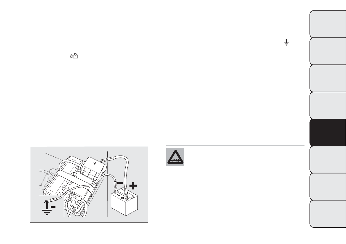
IN AN EMERGENCY
STARTING THE ENGINE
Contact a Fiat Dealership immediately if instrument
panel warning light
stays on constantly.
JUMP STARTING
If the battery is flat, the engine may be started using
an auxiliary battery with the same capacity or a
little higher than the flat one.
Proceed as follows to start the car:
❒ connect the positive terminals (sign + near the
terminal) of the two batteries with a jump lead
fig. 122
❒ with a second lead, connect the negative terminal
– of the auxiliary battery to an earth point
on
the engine or the gearbox of the car to be started;
❒ start the engine;
❒ when the engine has been started, remove the
leads reversing the order above.
If after a few attempts the engine does not start, do
not persist but contact a Fiat Dealership.
IMPORTANT Do not directly connect the negative
terminals of the two batteries: sparks could ignite
explosive gas released from the battery. If the
auxiliary battery is installed on another car, prevent
accidental contact between metallic parts of the two
cars.
Never use a fast battery-charger to start
the engine as this could damage the
electronic systems of your car, particularly
the ignition and fuel supply control units.
fig. 122
F0Q0765
161
GETTING TO KNOW
YOUR CAR
SAFETY
STARTING AND
DRIVING
WARNING LIGHTS
AND MESSAGES
IN AN
EMERGENCY
SERVICING AND
MAINTENANCE
TECHNICAL
SPECIFICATIONS
INDEX
WARNING
This procedure must be performed by
expert personnel because incorrect
actions could cause electrical discharge of
considerable intensity. Furthermore, battery
fluid is poisonous and corrosive: avoid contact
with skin and eyes. Keep naked flames and
lighted cigarettes away from the battery and do
not cause sparks.
BUMP STARTING
Never bump start the engine by pushing, towing or
coasting downhill.
IMPORTANT Remember that the brake servo and
electrical power steering system are not active until
the engine is started. A much greater effort will
therefore be required to use the brake pedal or turn
the steering wheel.
CHANGING A WHEEL
GENERAL INSTRUCTIONS
The car is equipped with the “Fix&Go Automatic
Kit”: see paragraph “Fix&Go Automatic Kit” for
instructions on how to use this device. As an
alternative to the “Fix&Go Automatic Kit” the car
may be equipped with a space-saver wheel: see
the instructions on the following pages for changing
the wheel.
WARNING
The space-saver wheel (for versions/
markets, where provided) is specific to
your car, do not use it on other models, or use
the space-saver wheel of other models on your
car.The space-saver wheel must only be used
in case of emergency. It must only be used
for the distance necessary to reach a service
point and the car speed must not exceed 80
km/h.The space-saver wheel has an orange
sticker that summarises the main cautions for
use and limitations. Never remove or cover
the sticker.The following information is
provided in four languages on the sticker :
"Important! For temporary use only! 80 km/h
max.! Replace with a standard wheel as soon as
possible. Never cover this indication". Never
apply a hub cap on a space-saver wheel.
162
GETTING TO KNOW
YOUR CAR
SAFETY
STARTING AND
DRIVING
WARNING LIGHTS
AND MESSAGES
IN AN
EMERGENCY
SERVICING AND
MAINTENANCE
TECHNICAL
SPECIFICATIONS
INDEX
WARNING
Alert other drivers that the car is
stationary in compliance with local
regulations: hazard warning lights, warning
triangle, etc.Any passengers on board should
leave the car, especially if it is heavily laden.
Passengers should stay away from on-coming
traffic while the wheel is being changed. On hills
or uneven roads, use chocks or appropriate
objects to block the wheels of the car.
WARNING
The car's driving characteristics will be
modified with the space-saver wheel
fitted. Avoid sudden starting or stopping, sharp
or fast turns.The total life of a space-saver
wheel is approximately 3000 km, after which it
must be replaced by another wheel of the
same type. Never install a tradit ional tyre on a
rim designed to be used as a space-saver wheel.
Have the tyre repaired and refitted as soon as
possible. Using two or more space-saver wheels
at the same time is forbidden. Do not grease the
threads of bolts before fitting them: they might
slip out.
WARNING
The jack provided is only intended to be
used for replacing wheels on the car
with which it is supplied, or on same-model
vehicles. Never use the jack for other purposes,
such as lifting other car models. Never use it
for repair operations under the car. Incorrectly
positioning the jack may cause the car to fall.
Do not use the jack for loads higher than the
one shown on its label. Never install snow
chains on the space-saver wheel; if a front tyre
(driving wheel) is punctured and you need to
use snow chains, use a standard wheel from the
rear axle and ins tall the space-saver wheel on
the rear axle. In this way, with two normal drive
wheels, it is possible to use snow chains.
WARNING
Fit the hub cap correctly to prevent it
from coming free in motion. Never
tamper with the inflating valve. Never introduce
tools of any kind between rim and tyre. Check
tyre and space-saver wheel pressures regular ly,
referring to the values shown in the "Technical
data" chapter.
163
GETTING TO KNOW
YOUR CAR
SAFETY
STARTING AND
DRIVING
WARNING LIGHTS
AND MESSAGES
IN AN
EMERGENCY
SERVICING AND
MAINTENANCE
TECHNICAL
SPECIFICATIONS
INDEX
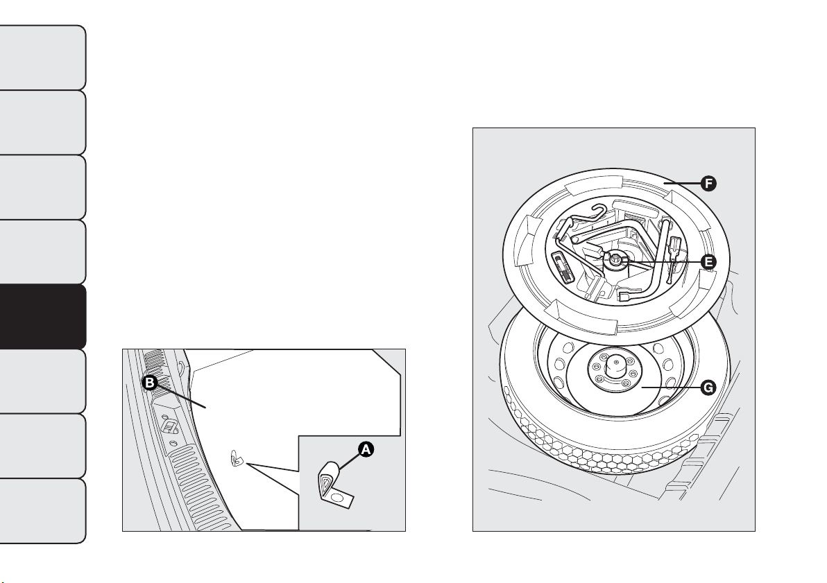
JACK
Please note that:
❒ the jack weight is 1.76 kg;
❒ the jack requires no adjustment;
❒ the jack cannot be repaired and in the event of a
fault it must be replaced by another original one;
❒ no tool other than its cranking device may be
fitted on the jack.
To change a wheel proceed as follows:
❒ stop the car in a position that is not dangerous for
on-coming traffic where you can change the wheel
safely. the ground must be flat and sufficiently
compact;
❒ turn the engine off and pull up the handbrake;
engage first gear or reverse; use handle A to
remove the rigid preformed cover B fig. 123;
❒ loosen fastener E fig. 124;
fig. 123
F0Q0732
fig. 124
F0Q0392
164
GETTING TO KNOW
YOUR CAR
SAFETY
STARTING AND
DRIVING
WARNING LIGHTS
AND MESSAGES
IN AN
EMERGENCY
SERVICING AND
MAINTENANCE
TECHNICAL
SPECIFICATIONS
INDEX
❒ for versions equipped with the “Fix&Go
Automatic” kit, take the tool box from the luggage
compartment;
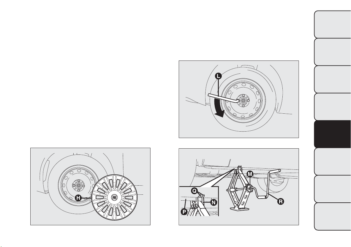
❒ for versions equipped with space-saver wheel,
loosen fastener E fig. 124, take tool box F, position
it near the wheel to be changed and then take
space-saver wheel G;
❒ remove hub cap H fig. 125 (versions with steel
rims) or remove the hub cap (versions with alloy
rims);
❒ loosen the bolts of the wheel to be replaced by
about one turn with the wrench provided L
fig. 126; if you have alloy rims, rock the car to
make it easier to separate the rim from the wheel
hub;
❒ operate device M fig. 127 so as to extend the jack,
until groove N on the upper part of the jack fits
correctly into the lower profile P visible on the car
body next to the indication Q (at approx. 72 cm
from the centre of the front wheel or 75 cm from
the centre of the rear wheel);
❒ alert any bystander that the car is about to be
raised; all persons should be kept away from
the car and nobody must touch it until it has been
lowered;
fig. 125
F0Q0393
fig. 126
F0Q0394
fig. 127
F0Q0395
165
GETTING TO KNOW
YOUR CAR
SAFETY
STARTING AND
DRIVING
WARNING LIGHTS
AND MESSAGES
IN AN
EMERGENCY
SERVICING AND
MAINTENANCE
TECHNICAL
SPECIFICATIONS
INDEX
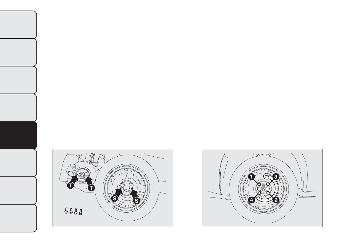
❒ fit handle R fig. 127 to operate the jack and raise
the car until the wheel is a few centimetres above
the ground;
❒ fully loosen the fastening bolts and remove the
wheel.
❒ make sure the contact surfaces between
space-saver wheel and hub are clean so that the
fastening bolts will not come loose;
❒ fit the space-saver wheel aligning the openings S
fig. 128 with the corresponding centering pins T;
❒ using the wrench provided, tighten the four
fastening bolts;
❒ turn the jack handle R fig. 127 to lower the car and
remove the jack;
❒ use the wrench provided to fully tighten the bolts,
passing alternately from one bolt to the opposite
one, as per the numerical sequence illustrated
in fig. 129.
REFITTING THE STANDARD WHEEL
Following the procedure described previously, raise
the car and remove the space-saver wheel.
Versions with steel rims
Proceed as follows:
❒ make sure the contact surfaces between standard
wheel and hub are clean so that the fastening
bolts will not come loose;
❒ fit the standard wheel aligning the openings S
fig. 128 with the corresponding centering pins T;
❒ using the wrench provided, tighten the fastening
bolts;
❒ lower the car and remove the jack;
❒ using the wrench provided, fully tighten the bolts
in the sequence shown in diagram fig. 129;
fig. 128
F0Q0396
fig. 129
F0Q0397
166
GETTING TO KNOW
YOUR CAR
SAFETY
STARTING AND
DRIVING
WARNING LIGHTS
AND MESSAGES
IN AN
EMERGENCY
SERVICING AND
MAINTENANCE
TECHNICAL
SPECIFICATIONS
INDEX
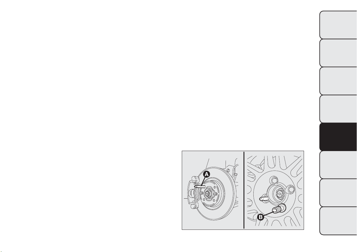
❒ fit the hub cap so that the inflation valve can exit
through the special slot visible on the cap itself;
❒ pressure-fit the hub cap starting from the parts
nearest to the inflation valve and continue until
it is completely fitted.
IMPORTANT If it is not fitted properly, the hub cap
may detach itself when the car is running.
Versions with alloy rims
Proceed as follows:
❒ tighten centering pin A fig. 130 in one of the fixing
bolt openings on the wheel hub;
❒ place the wheel on the pin and tighten the bolts
using the wrench provided. Bolt insertion is eased
by the use of the extension B provided;
❒ undo centering pin A and tighten the last fastening
bolt;
❒ lower the car and remove the jack;
❒ using the wrench provided, fully tighten the bolts
in the same sequence shown previously for the
space-saver wheel (see fig. 129);
❒ refit the hub cap.
fig. 130
F0Q0217
167
GETTING TO KNOW
YOUR CAR
SAFETY
STARTING AND
DRIVING
WARNING LIGHTS
AND MESSAGES
IN AN
EMERGENCY
SERVICING AND
MAINTENANCE
TECHNICAL
SPECIFICATIONS
INDEX
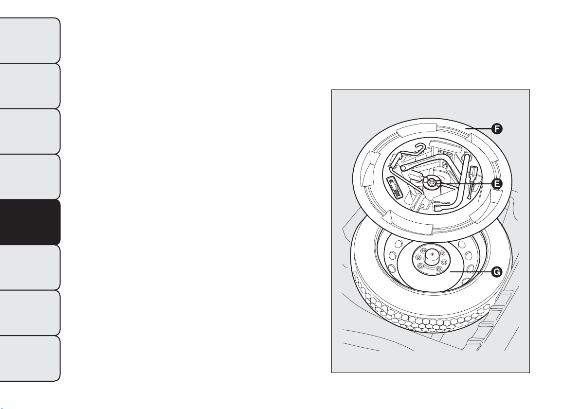
At the end of operation
Proceed as follows:
❒ arrange the space-saver wheel G fig. 131 in the
specific compartment in the luggage compartment;
❒ insert the partially open jack into container F
and force it slightly into its housing so that it does
not vibrate when the car is moving;
❒ put the tools back into their places in the
container;
❒ stow the container complete with tools on the
space-saver wheel and secure everything with
clamping device E;
❒ correctly reposition the rigid preformed cover in
the luggage compartment.
fig. 131
F0Q0392
168
GETTING TO KNOW
YOUR CAR
SAFETY
STARTING AND
DRIVING
WARNING LIGHTS
AND MESSAGES
IN AN
EMERGENCY
SERVICING AND
MAINTENANCE
TECHNICAL
SPECIFICATIONS
INDEX
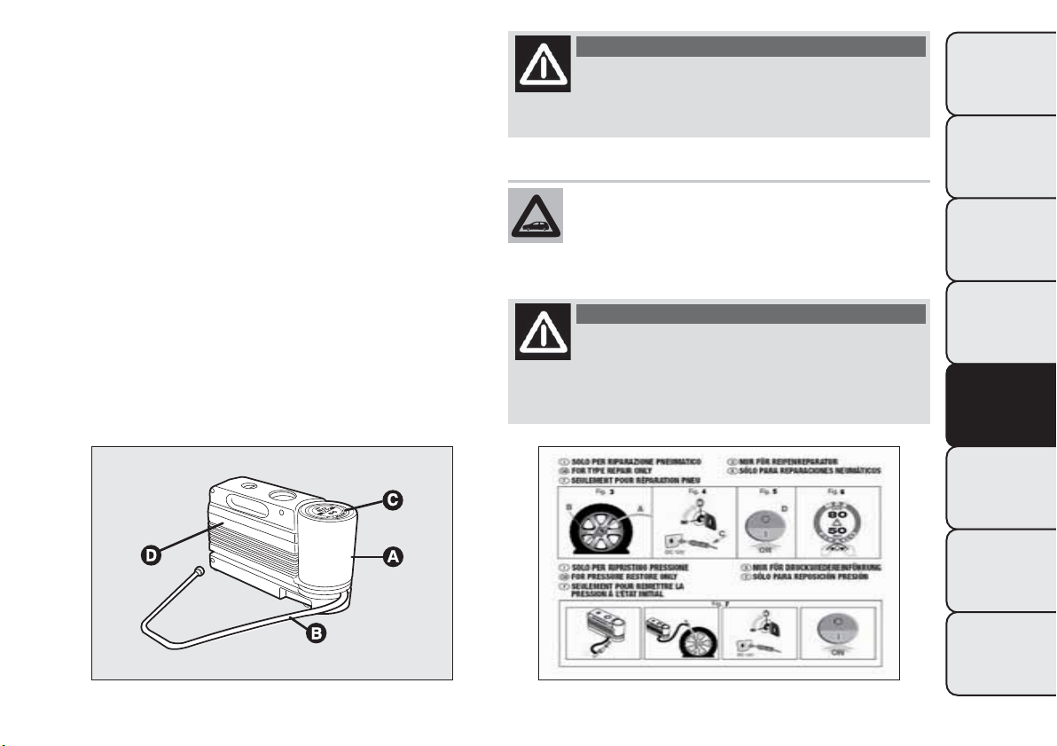
FIX&GO Automatic KIT
The Fix&Go Automatic kit is located in a special
container in the boot.
The kit includes fig. 132:
❒ a cylinder A containing sealing fluid and fitted with:
filling tube B and adhesive label C with the wording
“max. 80 km/h” to be placed in a position clearly
visible for the driver (e.g. on the dashboard)
after repairing the tyre;
❒ an information leaflet fig. 133, providing
instructions for using the kit correctly. This
booklet should be given to the persons charged
with handling the tyre treated with this kit;
❒ a compressor D including a pressure gauge and
connections, found in the compartment;
❒ a pair of protective gloves located in the side
compartment of the compressor;
❒ adapters for inflating different elements.
WARNING
Give the booklet to the technicians who
will be handling the tyre that was
treated using the kit.
In the event of a puncture caused by
foreign bodies, the kit may be used to
repair tyres showing damages on the
track or shoulder up to max 4 mm diameter.
WARNING
Holes and damage on the tyre side walls
cannot be repaired. Do not use the kit
if the tyre was damaged as a result of being
used when underinflated.
fig. 132
F0Q0510
fig. 133
F0Q0511
169
GETTING TO KNOW
YOUR CAR
SAFETY
STARTING AND
DRIVING
WARNING LIGHTS
AND MESSAGES
IN AN
EMERGENCY
SERVICING AND
MAINTENANCE
TECHNICAL
SPECIFICATIONS
INDEX
WARNING
If the wheel rim has been damaged
(bent so as to cause air to leak), the tyre
may not be re paired. Do not remove foreign
bodies (screws or nails) from the tyre.
IMPORTANT INFORMATION:
The sealing fluid of the quick tyre repair kit is
effective with external temperatures of between
−20°C and +50°C.
WARNING
Never operate the compressor for longer
than 20 consecutive minutes. Risk of
overheating.The kit is not suitable for definitive
repairs, so the repaired tyres may only be
used temporarily.
Dispose of the cylinder and the sealing
fluid properly. Have the sealing fluid and
the cylinder disposed of in compliance
with national and local regulations.
WARNING
The cylinder contains ethylene glycol
and latex: it may cause an allergic
reaction. It is harmful if swallowed. It is irritant
for the eyes in case of contact. May cause
irritation if inhaled or on contact.Avoid contact
with the eyes, skin and clothes. In the event of
contact, rinse immediately with plenty of water.
If ingested, do not induce vomiting. Rinse out
your mouth, drink large quantities of water and
seek immediate medical attention. Keep away
from children.The product must not be used
by asthmatics. Do not inhale the vapours during
insertion and suction. Call a doctor immediately
if allergic reactions are noted. Store the
cylinder in the specific compartment, away
from sources of heat.The sealing fluid has an
expiry date. Replace the cylinder containing
out-of-date sealing fluid.
170
GETTING TO KNOW
YOUR CAR
SAFETY
STARTING AND
DRIVING
WARNING LIGHTS
AND MESSAGES
IN AN
EMERGENCY
SERVICING AND
MAINTENANCE
TECHNICAL
SPECIFICATIONS
INDEX
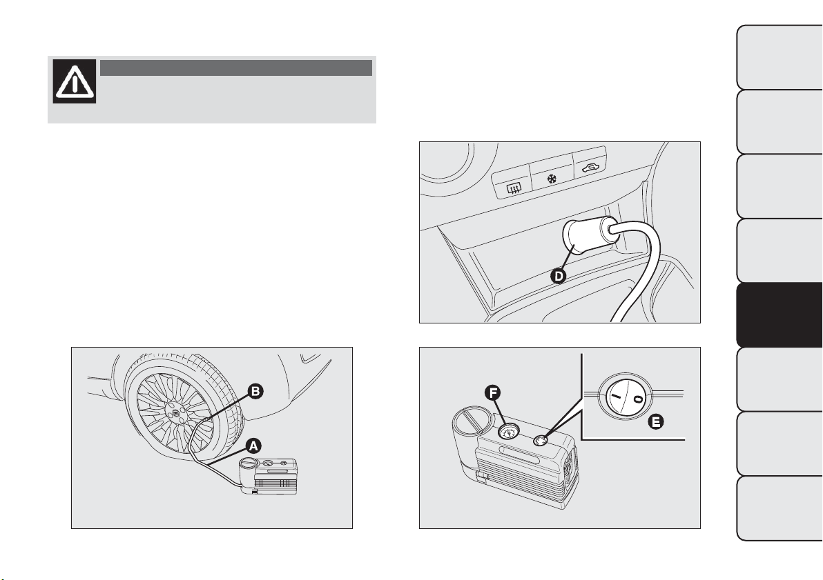
INFLATING PROCEDURE
WARNING
Wear the protective gloves provided
with the kit .
Proceed as follows:
❒ operate the handbrake. Unscrew the tyre valve
cap, take out the flexible filler pipe A fig. 134
and tighten the ring nut B on the tyre valve;
❒ make sure that switch E fig. 136 for the
compressor is in position 0 (off), start the engine,
insert plug D fig. 135 into the cigar lighter socket
and switch on the compressor by placing switch
E fig. 136 in position I (on). Inflate the tyre to the
pressure specified in the "Cold tyre pressures"
paragraph in "Technical data" chapter. Check tyre
pressure on pressure gauge F fig. 136 with
compressor off to obtain a more precise reading;
❒ if after 5 minutes it is still impossible to reach at
least 1.5 bar, disengage the compressor from the
valve and power socket, then move the car
forwards by approx. 10 metres in order to
distribute the sealing fluid inside the tyre evenly,
then repeat the inflation operation;
fig. 134
F0Q0513
fig. 135
F0Q0515
fig. 136
F0Q0516
171
GETTING TO KNOW
YOUR CAR
SAFETY
STARTING AND
DRIVING
WARNING LIGHTS
AND MESSAGES
IN AN
EMERGENCY
SERVICING AND
MAINTENANCE
TECHNICAL
SPECIFICATIONS
INDEX
❒ if after this operation it is still impossible after 5
minutes to reach at least 1.8 bar, do not start
driving since the tyre is excessively damaged and
the kit cannot guarantee proper hold, contact
a Fiat Dealership.
❒ if reaching the tyre pressure specified in paragraph
“Inflation pressure” in chapter “Technical Data”,
start driving immediately;
❒ after having driven for about 10 minutes, stop and
recheck the tyre pressure; remember to apply the
handbrake;
❒ if, on the other hand, the pressure is at least 1.8
bar, restore the correct pressure (with the engine
running and the handbrake applied) and resume
driving;
❒ drive with the utmost care to the nearest Fiat
Dealership.
WARNING
Apply the adhesive label where it can be
easily seen by the driver as a reminder
that the tyre has been treated with the Fix&Go
Automatic kit. Drive carefully, particularly on
bends. Do not exceed 80 km/h. Do not
accelerate or brake suddenly.
WARNING
If the pressure has fallen below 1.8 bar,
do not drive any further: the Fix&Go
Automatic kit cannot guarantee proper hold
because the tyre is too damaged. Contact a Fiat
Dealership.
WARNING
You must always indicate that the tyre
was repaired using the Fix&Go
Automatic kit. Give the booklet to the
technicians who will be handling the tyre that
was treated using the kit.
172
GETTING TO KNOW
YOUR CAR
SAFETY
STARTING AND
DRIVING
WARNING LIGHTS
AND MESSAGES
IN AN
EMERGENCY
SERVICING AND
MAINTENANCE
TECHNICAL
SPECIFICATIONS
INDEX
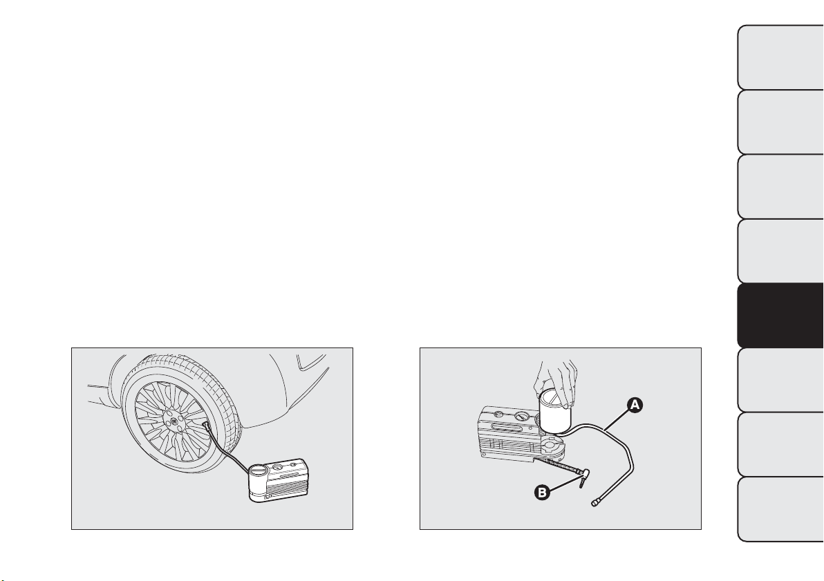
CHECKING AND RESTORINGTYRE
PRESSURE
The compressor may also be used for restoring
pressure only. Release the quick coupling and
connect directly to the tyre valve fig. 137; in this way,
the cylinder will not be connected to the
compressor and no sealing fluid will be injected.
CYLINDER REPLACEMENT
To replace the cylinder, proceed as follows:
❒ disconnect coupling B fig. 138;
❒ turn the cylinder to be replaced anticlockwise and
raise it;
❒ fit the new cylinder and turn it clockwise;
❒ connect coupling B to the cylinder and fit
transparent pipe A in the specific compartment.
fig. 137
F0Q0517
fig. 138
F0Q0512
173
GETTING TO KNOW
YOUR CAR
SAFETY
STARTING AND
DRIVING
WARNING LIGHTS
AND MESSAGES
IN AN
EMERGENCY
SERVICING AND
MAINTENANCE
TECHNICAL
SPECIFICATIONS
INDEX
CHANGING A BULB
GENERAL INSTRUCTIONS
❒ Before changing a bulb check the contacts for
oxidation;
❒ Burnt bulbs must be replaced by others of the
same type and power;
❒ after replacing a headlight bulb, always check its
alignment;
❒ when a light is not working, check that the
corresponding fuse is intact before changing a bulb.
For the location of fuses, refer to the paragraph
“If a fuse blows” in this section;
WARNING
Modifications or repairs to the electric
system that are not carried out properly
or do not take the system technical
specifications into account can cause
malfunctions leading to the risk of fire.
WARNING
Halogen bulbs contain pressurised gas,
in the case of breakage they may burst.
Halogen bulbs must be handled holding
the metallic part only.Touching the
transparent part of the bulb with your
fingers may reduce the intensity of the emitted
light and even reduce the lifespan of the bulb. In
case of accidental contact, wipe the bulb with
a cloth moistened with alcohol and let the bulb
dry.
If possible, we recommend have bulbs
replaced by a Fiat Dealership.The correct
operation and aiming of the outer lights
are absolutely essential for the safety of the car
and of compliance with law.
Due to the high supply voltage, gas
discharge bulbs (Bi-Xenon) (for versions/
markets, where provided) must only be
replaced by a s pecialist technician: danger of
death! Contact a Fiat Dealership.
IMPORTANT When the weather is cold or damp or
after heavy rain or washing, the surface of headlights
or rear lights, may steam up and/or form drops of
condensation on the inside. This is a natural
phenomenon due to the difference in temperature
and humidity between the inside and the outside
of the glass which does not indicate a fault and does
not compromise the normal operation of lighting
devices. The mist disappears quickly when the lights
are turned on, starting from the centre of the
diffuser, extending progressively towards the edges.
174
GETTING TO KNOW
YOUR CAR
SAFETY
STARTING AND
DRIVING
WARNING LIGHTS
AND MESSAGES
IN AN
EMERGENCY
SERVICING AND
MAINTENANCE
TECHNICAL
SPECIFICATIONS
INDEX
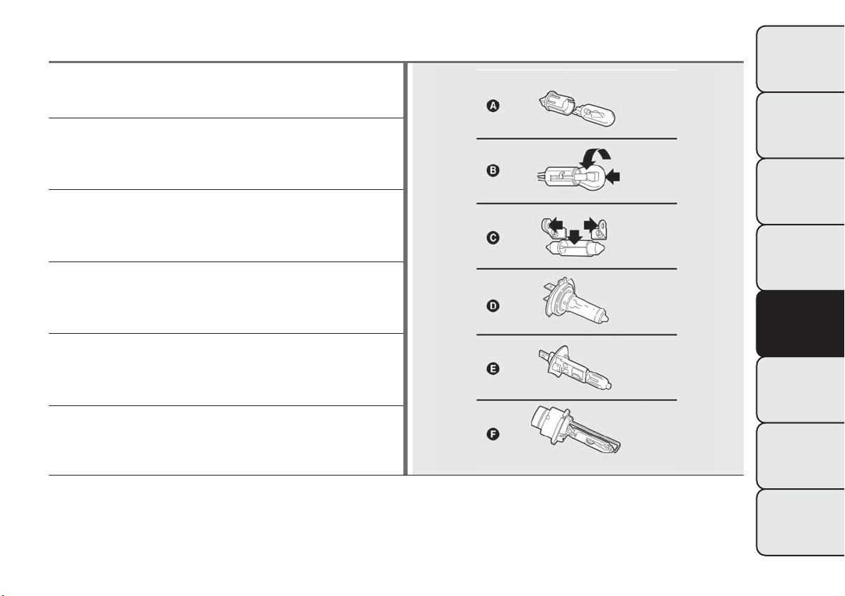
TYPES OF BULBS
Various types of bulbs are fitted to your car:
All-glass bulbs: (type A) press-fitted. Pull to remove.
Bayonet type bulbs: (type B) to remove them press the
bulb and turn it anticlockwise.
Tubular bulbs: (type C) release them from their contacts
to remove.
Halogen bulbs: (type D) to remove the bulb, release the
clip holding the bulb in place.
Halogen bulbs: (type E) to remove the bulb, release the
clip holding the bulb in place.
Gas discharge bulb (Xenon): (type F) to replace them
contact a Fiat Dealership.
175
GETTING TO KNOW
YOUR CAR
SAFETY
STARTING AND
DRIVING
WARNING LIGHTS
AND MESSAGES
IN AN
EMERGENCY
SERVICING AND
MAINTENANCE
TECHNICAL
SPECIFICATIONS
INDEX
Bulbs
Use Type Power Re. Figure
Main beam headlights H1 55 W E
Longlife dipped headlights H1 55 W D
Dipped headlights with gas discharge bulbs
(for versions/markets, where provided)
D2R 35 W F
Longlife front side lights W5W 5 W A
Front fog lights (for versions/markets, where provided) H11 55 W E
Front direction indicators PY24W 24W B
Side direction indicators WY5W 5 W A
Rear direction indicators R10W 10 W B
Rear side lights/rear fog lights P5/21W 5 W/21 W B
Rear side lights/break lights P5/21W 5 W/21 W B
Third brake light (additional brake light) W2.3W 2.3 W A
Reverse lights P21W 21 W B
Number plate lights W5W 5 W A
Front roof light C10W 2x10 W C
Rear roof light (for versions/markets, where provided) C10W 10 W C
Glove compartment light C5W 5W C
Luggage compartment roof light W5W 5W A
Courtesy mirror lights (for versions/markets, where
provided)
C5W 5 W C
176
GETTING TO KNOW
YOUR CAR
SAFETY
STARTING AND
DRIVING
WARNING LIGHTS
AND MESSAGES
IN AN
EMERGENCY
SERVICING AND
MAINTENANCE
TECHNICAL
SPECIFICATIONS
INDEX
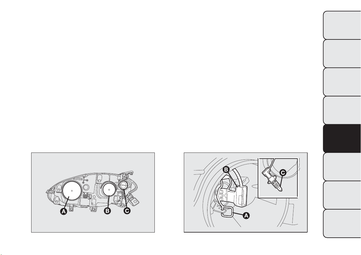
REPLACING EXTERIOR BULBS
For the type of bulb and power rating, see “Changing
a bulb" paragraph.
FRONT LIGHT CLUSTERS
The front light clusters contain side lights, dipped
headlights, main beam headlights and direction
indicator bulbs.
The bulbs are arranged inside the light cluster as
follows fig. 139:
A
Side lights/daytime running lights and main beam
headlights
B
Dipped headlights
C
Direction indicators
DIPPED HEADLIGHTS
To change the bulb, proceed as follows:
❒ remove the protective cover B fig. 139;
❒ release the bulb holding clip A fig. 140;
❒ disconnect the electrical connector B;
❒ remove bulb C and replace it;
❒ fit the new bulb, ensuring that the outline of the
metal part coincides with the splining on the
curve of the headlight. Then reconnect the
electrical connector B and reattach the bulb
holding clip A;
❒ refit the protective cover A fig. 139.
fig. 139
F0Q0704
fig. 140
F0Q0705
177
GETTING TO KNOW
YOUR CAR
SAFETY
STARTING AND
DRIVING
WARNING LIGHTS
AND MESSAGES
IN AN
EMERGENCY
SERVICING AND
MAINTENANCE
TECHNICAL
SPECIFICATIONS
INDEX
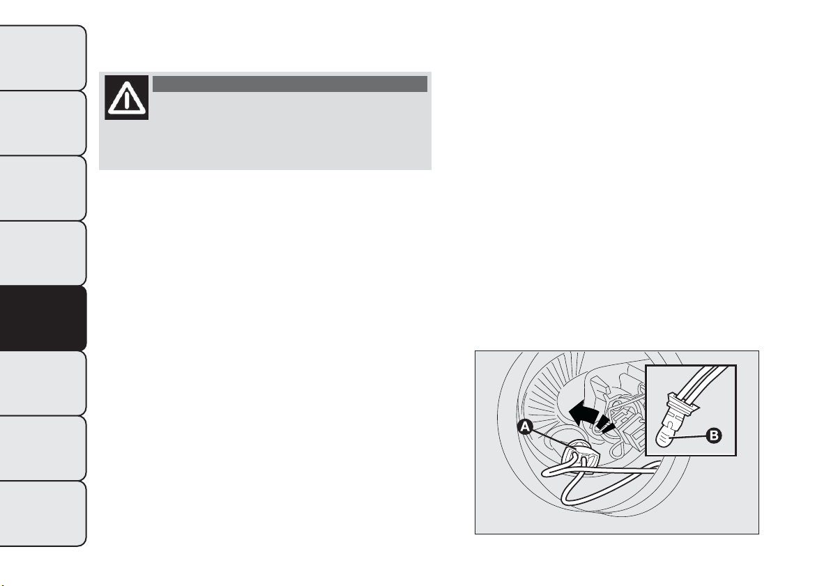
With gas discharge bulbs (Bi-Xenon)
(for versions/markets, where provided)
WARNING
Due to the high power supply voltage,
gas discharge bulbs (Bi-Xenon) should
only be replaced by specialised personnel:
danger of death! Contact a Fiat Dealership.
SIDE LIGHTS
To change the bulb, proceed as follows:
❒ remove the protective cover A fig. 139;
❒ turn the bulb holder A fig. 141 anticlockwise and
remove it;
❒ remove the bulb B and replace it;
❒ refit the new bulb, put the bulb holder A fig. 141
back into place and then refit the protective cover
B fig. 139 properly.
fig. 141
F0Q0706
178
GETTING TO KNOW
YOUR CAR
SAFETY
STARTING AND
DRIVING
WARNING LIGHTS
AND MESSAGES
IN AN
EMERGENCY
SERVICING AND
MAINTENANCE
TECHNICAL
SPECIFICATIONS
INDEX
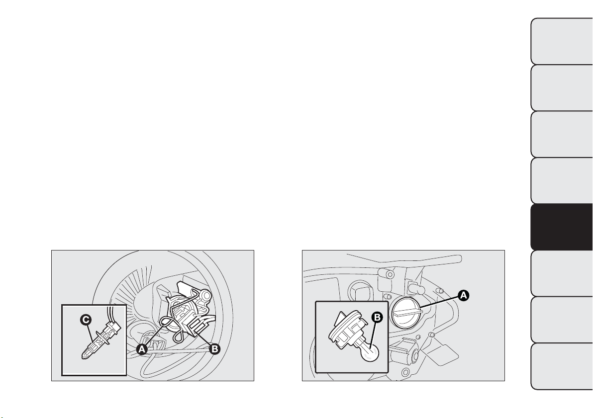
MAIN BEAM HEADLIGHTS
To change the bulb, proceed as follows:
❒ remove the protective cover A fig. 139;
❒ release the bulb holding clip A fig. 142;
❒ remove bulb C and replace it;
❒ fit the new bulb, ensuring that the outline of the
metal part coincides with the splining on the
curve of the headlight. Then reconnect the
electrical connector B and reattach the bulb
holding clip A;
❒ refit the protective cover B fig. 139.
DIRECTION INDICATORS
Front
To change the bulb, proceed as follows:
❒ rotate the protective cover C fig. 139
anticlockwise;
❒ remove the bulb B fig. 143 and replace it;
❒ refit the protective cover A.
fig. 142
F0Q0707
fig. 143
F0Q0708
179
GETTING TO KNOW
YOUR CAR
SAFETY
STARTING AND
DRIVING
WARNING LIGHTS
AND MESSAGES
IN AN
EMERGENCY
SERVICING AND
MAINTENANCE
TECHNICAL
SPECIFICATIONS
INDEX
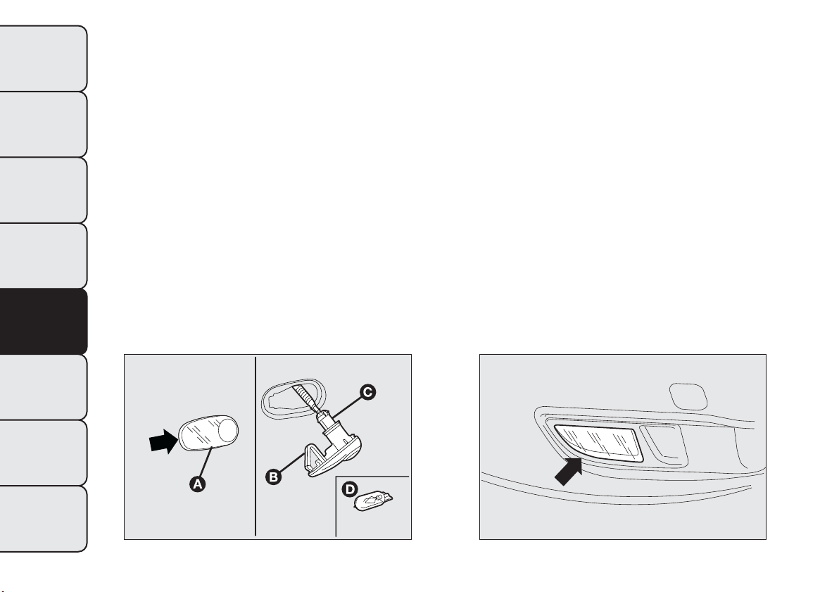
Side
To change the bulb, proceed as follows:
❒ adjust the lens A fig. 144 to compress in the
internal catch B, then pull the cluster outwards;
❒ turn the bulb holder C anticlockwise, extract the
press-fitted bulb D and replace it;
❒ refit the bulb holder C in the lens and turn it
clockwise;
❒ refit the cluster making sure that the internal catch
B clips into position.
FOG LIGHTS
For replacing the bulb fig. 145 contact a Fiat
Dealership.
fig. 144
F0Q0709
fig. 145
F0Q0710
180
GETTING TO KNOW
YOUR CAR
SAFETY
STARTING AND
DRIVING
WARNING LIGHTS
AND MESSAGES
IN AN
EMERGENCY
SERVICING AND
MAINTENANCE
TECHNICAL
SPECIFICATIONS
INDEX
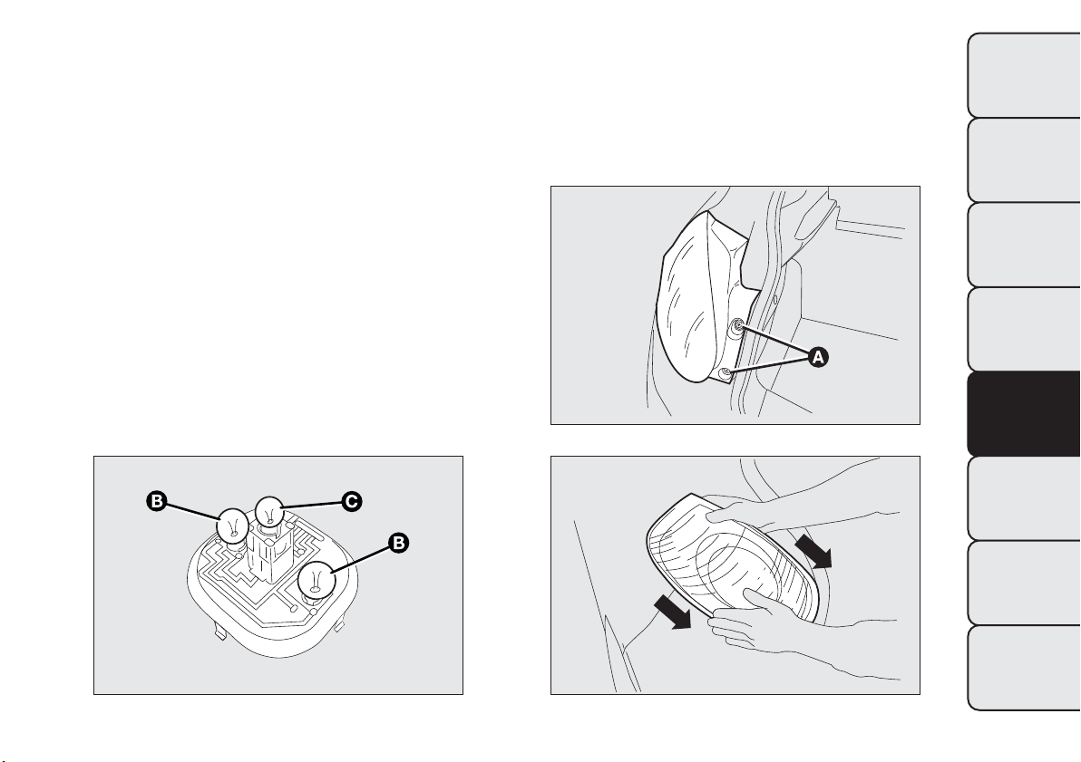
REAR LIGHT CLUSTERS
The rear light clusters contain side lights, direction
indicators and brake lights (stop) bulbs.
The bulbs are arranged inside the light cluster as
follows fig. 146:
B
Side lights/brake light (double light)
C
Direction indicators
To change the bulb, proceed as follows:
❒ open the luggage compartment and loosen the
two rear light cluster fastening screws A fig. 147;
❒ extract the light cluster by removing it with both
hands in the direction indicated by the arrows
fig. 148;
❒ disconnect the electrical connector and, adjusting
the three retaining tabs, remove the protective
cover A fig. 149. Then, replace the concerned bulb.
fig. 146
F0Q0714
fig. 147
F0Q0715
fig. 148
F0Q0739
181
GETTING TO KNOW
YOUR CAR
SAFETY
STARTING AND
DRIVING
WARNING LIGHTS
AND MESSAGES
IN AN
EMERGENCY
SERVICING AND
MAINTENANCE
TECHNICAL
SPECIFICATIONS
INDEX
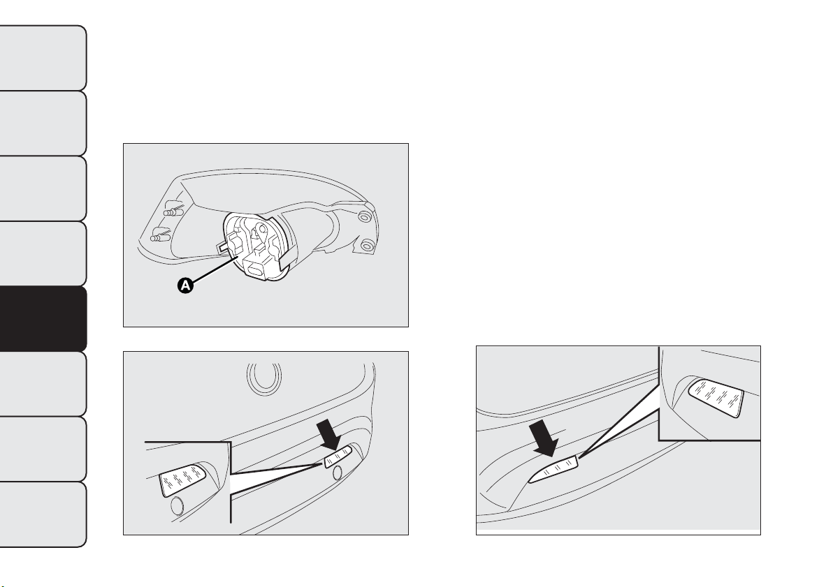
REVERSE LIGHT
For bulb replacement fig. 150, contact a Fiat
Dealership.
REAR FOG LIGHT
For bulb replacement fig. 151, contact a Fiat
Dealership.
3
rd
BRAKE LIGHTS
To change the bulb proceed as follows:
❒ open the luggage compartment;
❒ remove the cover A fig. 152;
❒ extract the lens unit B fig. 153 and disconnect the
electrical connector;
❒ press in the tabs C fig. 153 and remove the bulb
holder;
❒ remove the snap-fitted bulb and replace it.
❒ refit the cover A fig. 152 and close the luggage
compartment.
fig. 149
F0Q0713
fig. 150
F0Q0711
fig. 151
F0Q0712
182
GETTING TO KNOW
YOUR CAR
SAFETY
STARTING AND
DRIVING
WARNING LIGHTS
AND MESSAGES
IN AN
EMERGENCY
SERVICING AND
MAINTENANCE
TECHNICAL
SPECIFICATIONS
INDEX

NUMBER PLATE LIGHTS
To replace the bulbs proceed as follows:
❒ operate in the point indicated by the arrows and
remove the lens units A fig. 154;
❒ turn the bulb holder B fig. 155 clockwise;
❒ remove bulb C and replace it.
fig. 152
F0Q0716
fig. 153
F0Q0751
fig. 154
F0Q0718
183
GETTING TO KNOW
YOUR CAR
SAFETY
STARTING AND
DRIVING
WARNING LIGHTS
AND MESSAGES
IN AN
EMERGENCY
SERVICING AND
MAINTENANCE
TECHNICAL
SPECIFICATIONS
INDEX
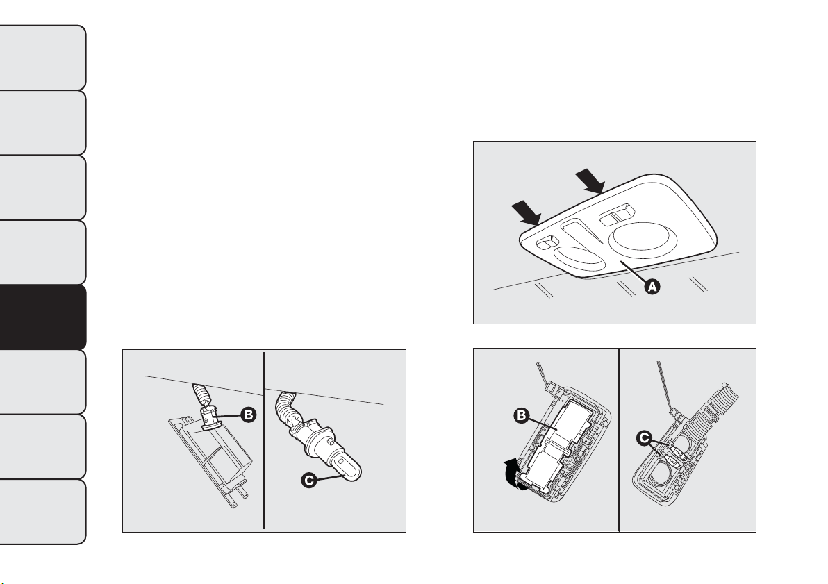
REPLACING INTERIOR BULBS
For the type of bulb and corresponding power rating,
see the paragraph "Changing a bulb".
FRONT ROOF LIGHT
To change the bulbs, proceed as follows:
❒ operate in the points indicated by the arrows and
remove light A fig. 156;
❒ open protective flap B fig. 157;
❒ replace the bulbs C releasing them from the side
contacts and making sure that the new bulbs are
correctly secured between the contacts;
❒ close flap B fig. 157 and fix roof light A fig. 156 in
its housing, making sure that it locks into place.
fig. 155
F0Q0719
fig. 156
F0Q0720
fig. 157
F0Q0721
184
GETTING TO KNOW
YOUR CAR
SAFETY
STARTING AND
DRIVING
WARNING LIGHTS
AND MESSAGES
IN AN
EMERGENCY
SERVICING AND
MAINTENANCE
TECHNICAL
SPECIFICATIONS
INDEX
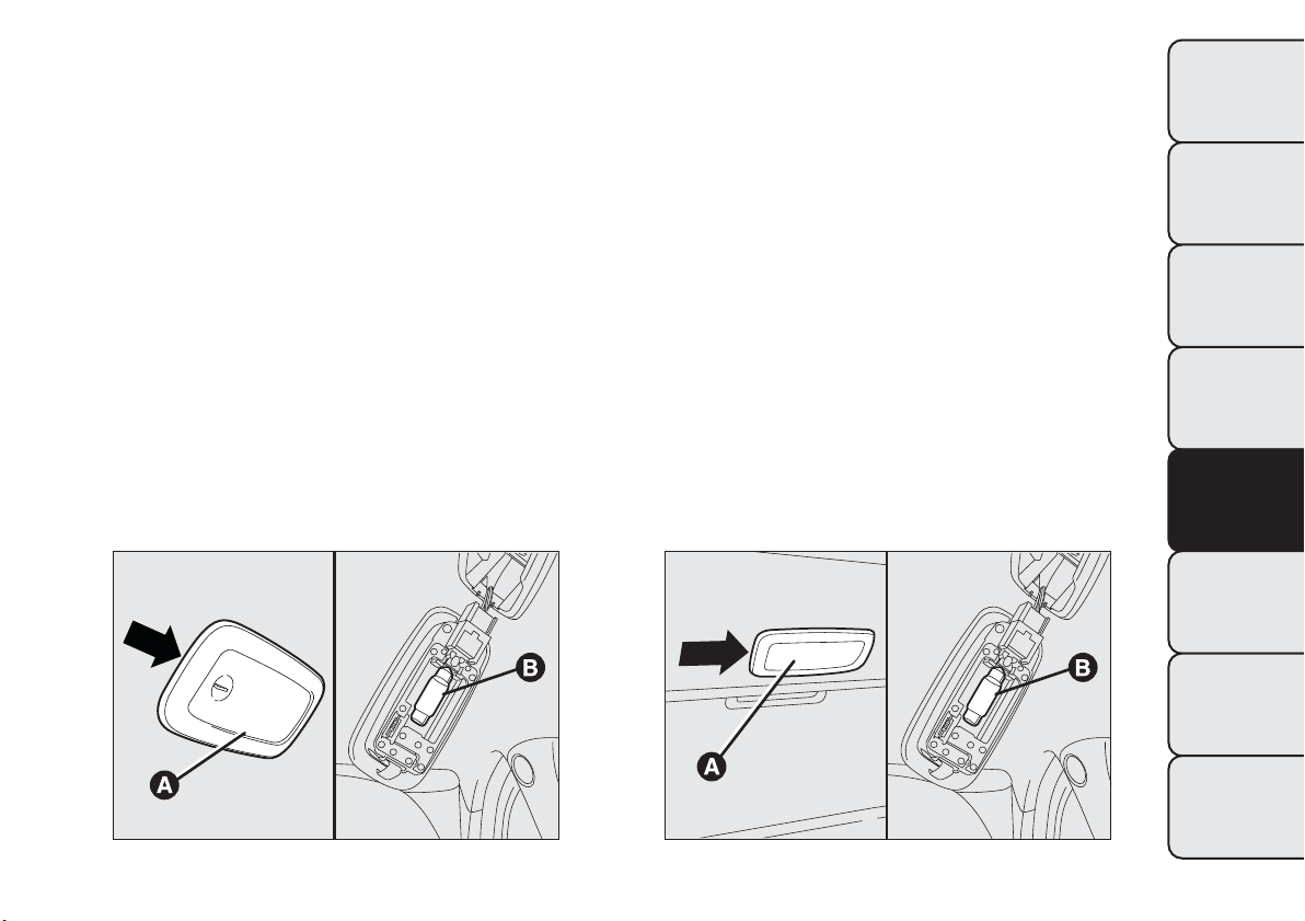
REAR ROOF LIGHT
Versions without sun roof
Proceed as follows to replace the bulbs:
❒ operate in the point shown by the arrow and
remove roof light A fig. 158;
❒ replace bulb B releasing it from the side contacts
and making sure the new bulb is correctly
fastened between the contacts.
Versions with sun roof
Proceed as follows to replace the bulbs:
❒ operate in the point shown by the arrow and
remove roof light A fig. 159;
❒ replace bulb B releasing it from the side contacts
and making sure the new bulb is correctly
fastened between the contacts.
fig. 158
F0Q0905
fig. 159
F0Q0906
185
GETTING TO KNOW
YOUR CAR
SAFETY
STARTING AND
DRIVING
WARNING LIGHTS
AND MESSAGES
IN AN
EMERGENCY
SERVICING AND
MAINTENANCE
TECHNICAL
SPECIFICATIONS
INDEX
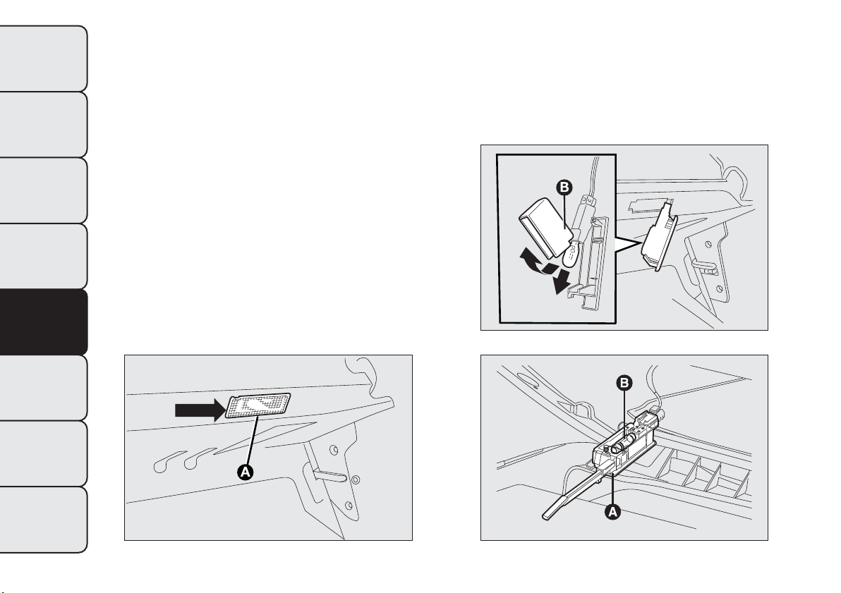
LUGGAGE COMPARTMENT ROOF LIGHT
To replace the bulb, proceed as follows:
❒ open the luggage compartment;
❒ remove the light A fig. 160 levering in the point
shown by the arrow;
❒ open protection B fig. 161 and replace the
snap-fitted bulb;
❒ re-close the protection B on the lens;
❒ refit the roof light A by inserting it in its correct
position firstly on one side and then pressing on
the other until it clicks into place.
GLOVE COMPARTMENT LIGHT
To change the bulbs, proceed as follows:
❒ open the glove compartment and extract roof light
A fig. 162;
❒ replace bulb B releasing it from the side contacts
and making sure the new bulb is correctly
fastened between the contacts.
fig. 160
F0Q0724
fig. 161
F0Q0725
fig. 162
F0Q0726
186
GETTING TO KNOW
YOUR CAR
SAFETY
STARTING AND
DRIVING
WARNING LIGHTS
AND MESSAGES
IN AN
EMERGENCY
SERVICING AND
MAINTENANCE
TECHNICAL
SPECIFICATIONS
INDEX
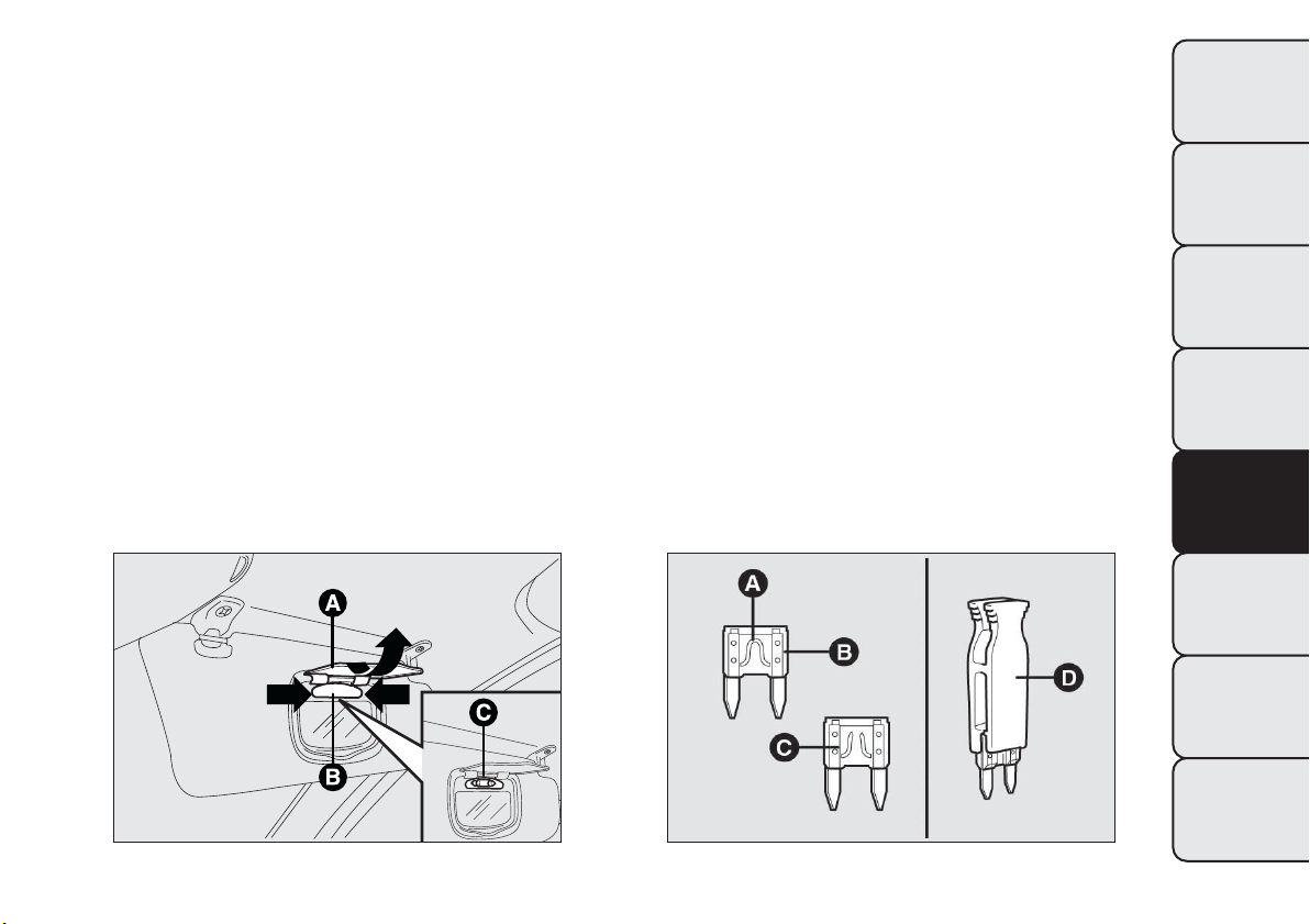
COURTESY MIRROR LIGHTS
(for versions/markets, where provided)
Replace the bulb as follows:
❒ open the mirror cover A fig. 163;
❒ extract light B levering in the points shown by the
arrows;
❒ replace bulb C releasing the side contacts, insert
the new bulb and make sure that it is correctly
locked between the contacts.
REPLACING FUSES
INTRODUCTION
Fuses protect the electrical system: they intervene
(blow) in the event of a failure or improper
intervention on the system.
When a device does not work, check the condition
of its protective fuse: the conductor element A
fig. 164 must be intact. If it is not, replace the blown
fuse with another with the same amperage (same
colour).
B = intact fuse;
C = fuse with damaged filament.
To facilitate fuse replacement, use the pliers D
hooked inside the fuse box lid on the dashboard
left-hand side.
Refer to the tables on the following pages to identify
the protective fuse.
fig. 163
F0Q0753
fig. 164
F0Q0220
187
GETTING TO KNOW
YOUR CAR
SAFETY
STARTING AND
DRIVING
WARNING LIGHTS
AND MESSAGES
IN AN
EMERGENCY
SERVICING AND
MAINTENANCE
TECHNICAL
SPECIFICATIONS
INDEX
WARNING
If the replaced fuse blows again, contact
a Fiat Dealership.
WARNING
Never replace a fuse with metal wires or
other material.
WARNING
Never replace a fuse with another with
a higher amp rating; DANGER OF FIRE.
WARNING
If a general protective fuse (MEGA-
FUSE, MIDI-FUSE, M AXI-FUSE) blows,
contact a Fiat Dealership.
WARNING
Before replacing a fuse, make sure that
the ignition key has been removed
and that all the other services are switched off
and/or disengaged.
WARNING
Contact a Fiat Dealer ship if a safety
system (airbags, brakes), engine system
(engine, gearbox) or steering system general
protection fuse blows.
FUSE LOCATION
The fuses are grouped in three fuse boxes:
❒ dashboard fuse box;
❒ engine compartment fuse box;
❒ luggage compartment fuse box.
188
GETTING TO KNOW
YOUR CAR
SAFETY
STARTING AND
DRIVING
WARNING LIGHTS
AND MESSAGES
IN AN
EMERGENCY
SERVICING AND
MAINTENANCE
TECHNICAL
SPECIFICATIONS
INDEX
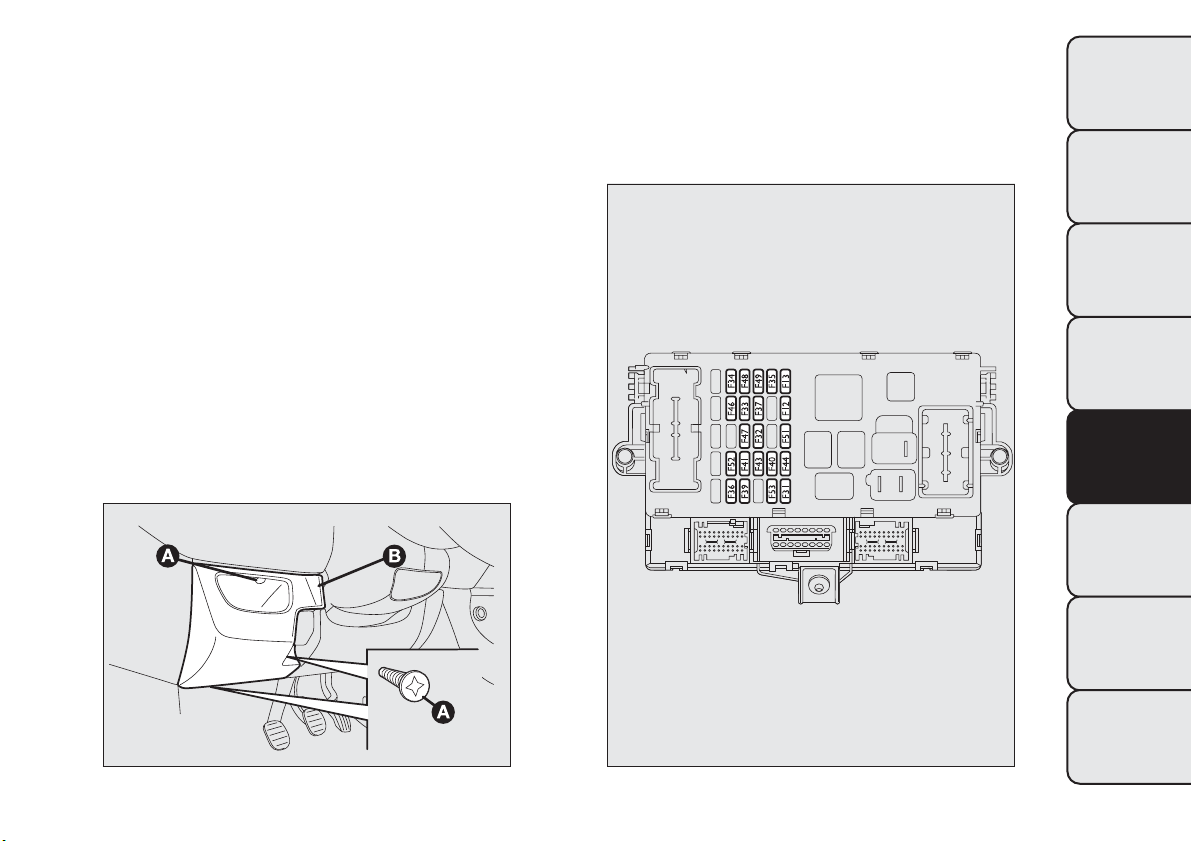
Dashboard fuse box
fig. 166
To access the dashboard fuse box, loosen the three
screws A in fig. 165 and remove the flap B.
fig. 165
F0Q0727
fig. 166
F0Q0778
189
GETTING TO KNOW
YOUR CAR
SAFETY
STARTING AND
DRIVING
WARNING LIGHTS
AND MESSAGES
IN AN
EMERGENCY
SERVICING AND
MAINTENANCE
TECHNICAL
SPECIFICATIONS
INDEX
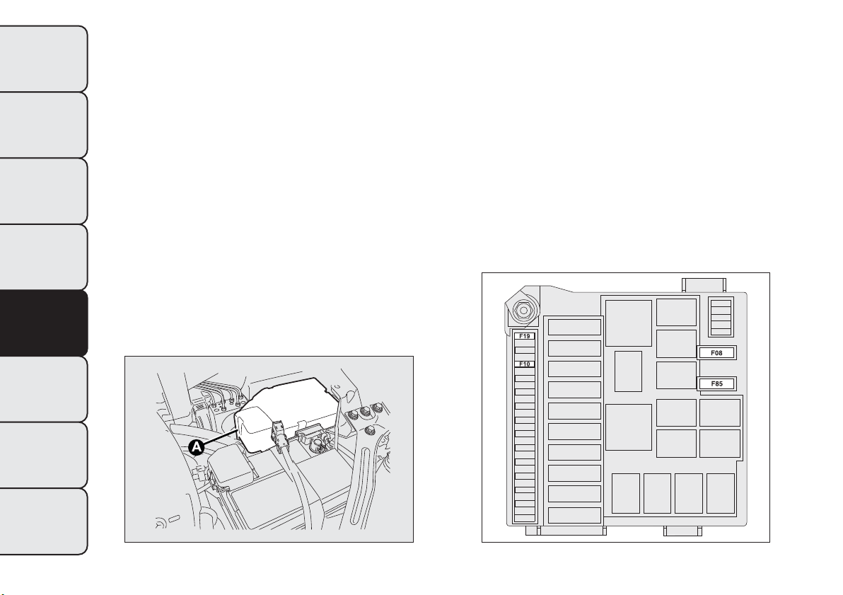
Engine compartment fuse box
next to the battery
fig. 168
(for versions/markets, where provided)
A second fuse box is located on the right-hand of the
engine compartment, next to the battery; to reach
it loosen the fixing screws and remove cover A
fig. 167.
The number identifying the electrical component
corresponding to each fuse is on the back of the
cover.
fig. 167
F0Q0816
fig. 168
F0Q0815
190
GETTING TO KNOW
YOUR CAR
SAFETY
STARTING AND
DRIVING
WARNING LIGHTS
AND MESSAGES
IN AN
EMERGENCY
SERVICING AND
MAINTENANCE
TECHNICAL
SPECIFICATIONS
INDEX
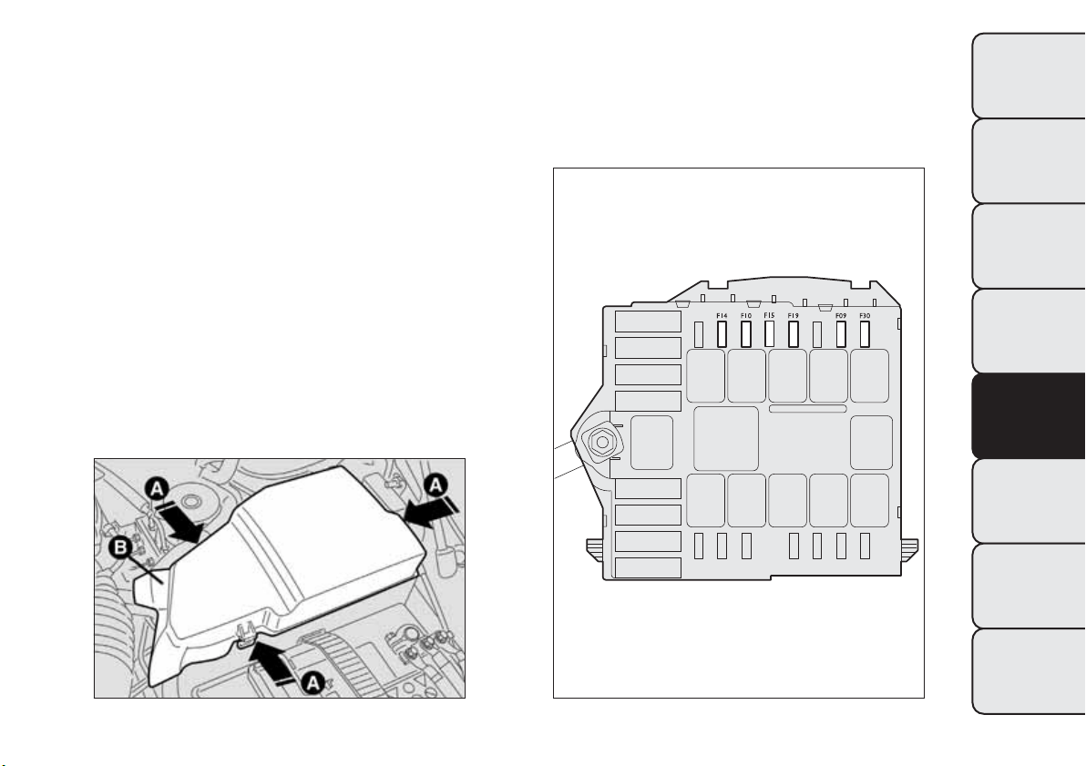
Engine compartment fuse box
next to the battery
fig. 170
(for versions/markets, where provided)
To access the fuse box next to the battery, press
retaining clips A fig. 169 and remove protection
cover B.
fig. 169
F0Q0498
fig. 170
F0Q0779
191
GETTING TO KNOW
YOUR CAR
SAFETY
STARTING AND
DRIVING
WARNING LIGHTS
AND MESSAGES
IN AN
EMERGENCY
SERVICING AND
MAINTENANCE
TECHNICAL
SPECIFICATIONS
INDEX
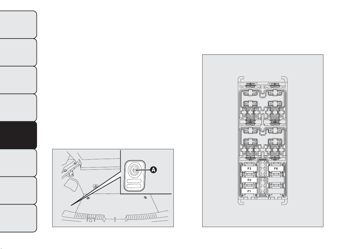
Luggage compartment fuse box
fig. 171
To access the fuse box located on the left side of the
luggage compartment, open lid A fig. 172.
fig. 171
F0Q0747
fig. 172
F0Q0776
192
GETTING TO KNOW
YOUR CAR
SAFETY
STARTING AND
DRIVING
WARNING LIGHTS
AND MESSAGES
IN AN
EMERGENCY
SERVICING AND
MAINTENANCE
TECHNICAL
SPECIFICATIONS
INDEX
FUSE SUMMARY TABLE
Dashboard fuse box FUSE AMPS
Right dipped headlight (halogen headlights) F12 7,5
Right dipped headlight (Bi-Xenon headlights) F12 15
Left dipped headlight (halogen headlights) F13 7,5
Left dipped headlight (Bi-Xenon headlights) F13 15
Reverse F35 5
3rd brake light F37 7,5
Rear fog light (driver's side) F53 7,5
Headlight alignment corrector system
(halogen headlights)
F13 7,5
Relay switch coils on engine compartment fuse box
(CVM)/Body Computer control unit (NBC)
F31 5
HI-FI audio system subwoofer amplifier F32 15
Left rear electric window F33 20
Right rear electric window F34 20
Control on brake pedal (NC contact)/Water presence
in diesel sensor/Air flow meter
F35 5
Central locking system control unit (CGP)
(door opening/closing, safe lock, tailgate release)
F36 20
Control on brake pedal (normally open contact NO)/
Instrument panel (NQS)/Gas discharge bulbs control
units on front headlights
F37 7,5
193
GETTING TO KNOW
YOUR CAR
SAFETY
STARTING AND
DRIVING
WARNING LIGHTS
AND MESSAGES
IN AN
EMERGENCY
SERVICING AND
MAINTENANCE
TECHNICAL
SPECIFICATIONS
INDEX
Dashboard fuse box FUSE AMPS
Radio and radio navigator /Radio setup//Blue&Me
TM
system/Alarm siren (CSA)/Alarm system on roof light/
Internal cooling unit/Tyre pressure monitoring system
control unit (CPP)/Diagnosis socket connector/Rear
roof lights
F39 10
Heated rear window F40 30
Electric door mirror demisters/Demisters on
windscreen jets
F41 7,5
Windscreen wiper/Bi-directional windscreen/rear
window washer electric pump system on steering
column stalk
F43 30
Current sockets/Cigar lighter F44 15
Electric sun roof motor F46 20
Front electric window (driver side) F47 20
Front electric window (passenger side) F48 20
Emergency control panel (lighting)/Right branch central
control panel (lighting, ASR switch) and left branch/
Steering wheel controls (lighting)/Control panel on
front roof light (lighting)/Volume sensing alarm system
control unit (deactivation)/Electric sun roof system
(control unit, control lighting)/Rain sensor/Dusk sensor
on rear view mirror/Heating pad activation controls on
front seats
F49 5
194
GETTING TO KNOW
YOUR CAR
SAFETY
STARTING AND
DRIVING
WARNING LIGHTS
AND MESSAGES
IN AN
EMERGENCY
SERVICING AND
MAINTENANCE
TECHNICAL
SPECIFICATIONS
INDEX
Dashboard fuse box FUSE AMPS
Internal cooling unit/Radio setup/Cruise Control lever/
Blue&Me
TM
system control unit/Parking sensor control
unit (NSP)/Air pollution sensor (AQS)/Automatic
climate control system/Electric door mirrors
(adjustment, folding)/Tyre pressure monitoring system
control unit (CPP)
F51 5
Rear window wiper F52 15
Instrument Panel (NQS) F53 7,5
195
GETTING TO KNOW
YOUR CAR
SAFETY
STARTING AND
DRIVING
WARNING LIGHTS
AND MESSAGES
IN AN
EMERGENCY
SERVICING AND
MAINTENANCE
TECHNICAL
SPECIFICATIONS
INDEX
Engine compartment fuse box FUSE AMPS
Main beam headlights F14 15
Left/right fog light/cornering light F30 15
Climate control fan F08 40
Headlight washer pump F09 30
Acoustic warning F10 10
Additional heater (PTC1) F15 30
Air conditioning compressor F19 7,5
Fuel pump F85 15
196
GETTING TO KNOW
YOUR CAR
SAFETY
STARTING AND
DRIVING
WARNING LIGHTS
AND MESSAGES
IN AN
EMERGENCY
SERVICING AND
MAINTENANCE
TECHNICAL
SPECIFICATIONS
INDEX
Luggage compartment fuse box FUSE AMPS
Front right seat movement F1 30
Front left seat movement F2 30
Front left seat heating F3 10
Front right seat heating F6 10
197
GETTING TO KNOW
YOUR CAR
SAFETY
STARTING AND
DRIVING
WARNING LIGHTS
AND MESSAGES
IN AN
EMERGENCY
SERVICING AND
MAINTENANCE
TECHNICAL
SPECIFICATIONS
INDEX
BATTERY RECHARGING
IMPORTANT The battery recharging procedure is
given as information only. You are advised to contact
a Fiat Dealership to have this operation performed.
Low amperage slow recharging for approximately
24 hours is advised. Charging for a longer time may
damage the battery.
Charge the battery as follows:
❒ disconnect the negative battery terminal;
❒ connect the charger cables to the battery
terminals, observing the polarity;
❒ turn on the charger;
❒ when it is recharged, turn the charger off before
disconnecting it from the battery;
❒ reconnect the negative battery terminal.
IMPORTANT If the car is equipped with an alarm
system, this has to be disabled using the remote
control (see the "Alarm" paragraph in "Knowing your
car" chapter).
WARNING
Battery fluid is poisonous and corrosive:
avoid contact wi th your skin and eyes.
The battery should be charged in a well
ventilated place, away from naked flames or
possible sources of spar ks: danger of explosion
and fire.
WARNING
Do not attempt to charge a frozen
battery: it must be thawed first,
otherwise it may explode. If freezing has
occurred, the battery should be checked by
skilled personnel to make sure that the internal
elements are not damaged and that the body
is not cracked, with the risk of leaking
poisonous and corrosive acid.
198
GETTING TO KNOW
YOUR CAR
SAFETY
STARTING AND
DRIVING
WARNING LIGHTS
AND MESSAGES
IN AN
EMERGENCY
SERVICING AND
MAINTENANCE
TECHNICAL
SPECIFICATIONS
INDEX
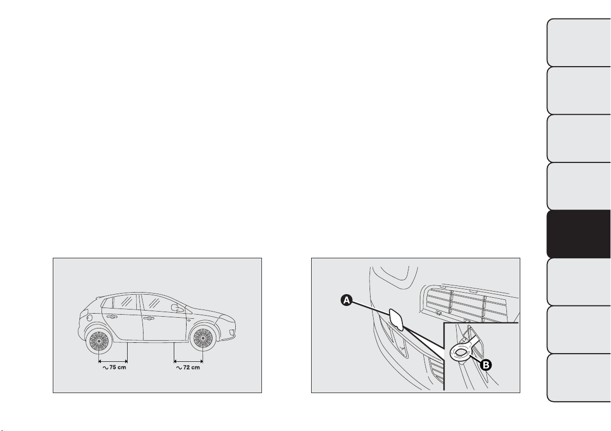
RAISING THE CAR
If the car needs to be jacked up, go to a Fiat
Dealership which is equipped with jack arms or
workshop lifts.
The car must only be lifted laterally by positioning
the end of the arms or the workshop lift in the
points illustrated in fig. 173
IMPORTANT For Sport versions, take care not to
damage the side skirts when lifting the car with
the workshop lift.
TOWING THE CAR
The tow hook, which is supplied with the car, is
housed in the tool box, under the carpet in the
luggage compartment.
ATTACHING THE TOW HOOK
Proceed as follows:
❒ release the cap by operating on tab A fig. 174–
fig. 175;
❒ take the tow hook B from its support;
❒ fully screw in the hook on the rear or front
threaded pin.
fig. 173
F0Q0729
fig. 174
F0Q0730
199
GETTING TO KNOW
YOUR CAR
SAFETY
STARTING AND
DRIVING
WARNING LIGHTS
AND MESSAGES
IN AN
EMERGENCY
SERVICING AND
MAINTENANCE
TECHNICAL
SPECIFICATIONS
INDEX
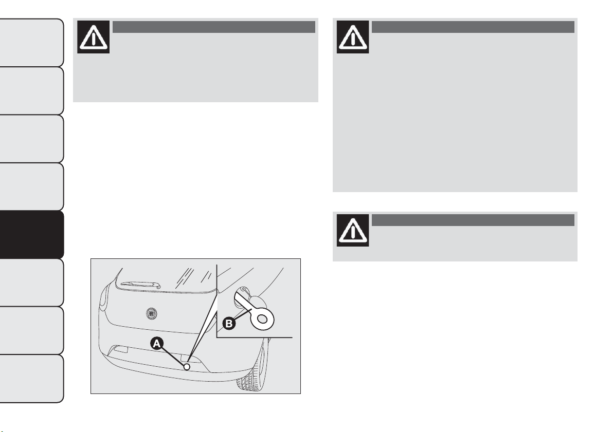
WARNING
Before towing, turn the ignition key to
MAR-ON and then to STOP without
removing it.The steering column will
automatically lock when the key is removed and
the wheels cannot be steered.
WARNING
Whilst towing, remember that as the
assistance of the brake servo and the
electric power steering is not available, greater
force needs to be exerted on the brake pedal
and more effort is required on the steering
wheel. Do not use flexible cables when towing
and avoid jerky movements. During towing,
make sure that the trailer hitch does not
damage any components it is touching.When
towing the car, it is compulsory to respect
specific highway code regulations relating to
the tow hook and procedures for towing on the
road.
WARNING
Do not start the engine while towing the
car.
fig. 175
F0Q0731
200
GETTING TO KNOW
YOUR CAR
SAFETY
STARTING AND
DRIVING
WARNING LIGHTS
AND MESSAGES
IN AN
EMERGENCY
SERVICING AND
MAINTENANCE
TECHNICAL
SPECIFICATIONS
INDEX
WARNING
Before tightening the hook clean the
threaded housing thoroughly. Make sure
that the hook is fully fastened in the housing
before towing the car.
WARNING
The front and rear tow hooks should be
used only for emergencies on the road.
You are allowed to tow the car for short
distances using an appropriate device
in accordance wi th the highway code (a rigid
bar), to move the vehicle on the road in
readiness for towing or transporting via a
breakdown vehicle .Tow hooks MUST NOT be
used to tow vehicles off the road or where there
are obstacles and/or for towing operat ions
using cables or other non-rigid devices.
Respecting the above conditions, towing must
take place with the two vehicles (one towing,
the other towed) aligned as much as possible
along the same centre line.
201
GETTING TO KNOW
YOUR CAR
SAFETY
STARTING AND
DRIVING
WARNING LIGHTS
AND MESSAGES
IN AN
EMERGENCY
SERVICING AND
MAINTENANCE
TECHNICAL
SPECIFICATIONS
INDEX

SERVICING AND MAINTENANCE
SCHEDULED SERVICING
Correct servicing is essential in guaranteeing a long
life for the car under the best conditions.
This is why Fiat has planned a series of checks and
services every 35,000 km.
However, scheduled servicing does not suffice to
cover all the car’s requirements: even in the initial
period before the 35,000 km service, and then
subsequently between one service and the next,
ordinary care is always required, such as routine
checks and topping up fluid levels, checking tyre
pressures etc.
IMPORTANT The Scheduled Servicing Plan coupons
are set out by the Manufacturer. Failure to have
them carried out may invalidate the warranty.
Scheduled Servicing is performed by all Fiat
Dealerships, at pre-established times.
If, during any service, the need arises for additional
replacements or repairs, these may be carried out
only with the explicit agreement of the Customer.
IMPORTANT It is advisable to inform a Fiat
Dealership of any small operating irregularities
without waiting for the next service.
If the car is used frequently for towing a trailer, the
interval between services should be reduced.
202
GETTING TO KNOW
YOUR CAR
SAFETY
STARTING AND
DRIVING
WARNING LIGHTS
AND MESSAGES
IN AN EMERGENCY
SERVICING AND
MAINTENANCE
TECHNICAL
SPECIFICATIONS
INDEX
SCHEDULED SERVICING PLAN
Thousands of miles 21 42 63 84 105
Thousands of km 35 70 105 140 175
Months 24 48 72 96 120
Check tyre condition/wear and adjust pressure, if necessary ●●●●●
Check operation of lighting system (headlights, direction indicators, hazard
warning lights, luggage compartment, passenger compartment, glove
compartment, instrument panel warning lights, etc.)
●●●●●
Check operation of windscreen washer system and adjust jets if necessary ●●●●●
Check windscreen/rear window wiper blades position/wear ●●●●●
Check condition and wear of front disc brake pads and operation of pad wear
indicator
●●●●●
Check condition and wear of rear disc brake pads ●●●●●
Visually inspect condition of: exterior bodywork, underbody protection, rigid
and flexible pipe sections (exhaust, fuel system, braking system), rubber
elements (boots, sleeves, bushes, etc.)
●●●●●
Check cleanliness of bonnet and luggage compartment locks, cleanliness and
lubrication of linkages
●●●●●
Check and, if necessary, top up fluid levels (brakes/hydraulic clutch, windscreen
washer, battery, engine cooling, etc.)
●●●●●
Check handbrake lever travel and adjust, if required ●●●●●
Visually inspect conditions of the accessory drive belt/s ●●
Check battery charge status and possibly recharge ●●●●●
Check emissions/fumes ●●●●●
203
GETTING TO KNOW
YOUR CAR
SAFETY
STARTING AND
DRIVING
WARNING LIGHTS
AND MESSAGES
IN AN EMERGENCY
SERVICING AND
MAINTENANCE
TECHNICAL
SPECIFICATIONS
INDEX
Thousands of miles 21 42 63 84 105
Thousands of km 35 70 105 140 175
Months 24 48 72 96 120
Check engine management system operation (through the diagnosis socket) ●●●●●
Replace accessory drive belt/s ●
Replacement of toothed timing drive belt
(*)
●
Replace fuel filter ●●
Air cleaner cartridge replacement ●●●●●
Change engine oil and replace oil filter (version without DPF)
(or every 24 months)
●●●●●
Change engine oil and replace oil filter (versions with DPF)
(**) (***)
Change brake fluid (or every 24 months) ●●
Change pollen filter (or every 15 months) ●●●●●
(*) Regardless of the distance covered, the timing belt must be changed every 4 years for particularly demanding use (cold climates,
town driving, long periods of idling) or at least every 5 years
(**) The actual interval for changing the oil and replacing the engine oil filter depends on the car usage conditions and is signalled by
the warning light or message (if present) on the instrument panel and must never exceed 24 months.
(***) If the car is mainly used for town driving, change the engine oil and filter every 12 months.
204
GETTING TO KNOW
YOUR CAR
SAFETY
STARTING AND
DRIVING
WARNING LIGHTS
AND MESSAGES
IN AN EMERGENCY
SERVICING AND
MAINTENANCE
TECHNICAL
SPECIFICATIONS
INDEX

PERIODIC CHECKS
Every 1,000 km or before long journeys, check and, if
necessary, restore:
❒ engine coolant, brake fluid and windscreen washer
fluid level;
❒ tyre inflation pressure and condition;
❒ operation of lighting system (headlamps, direction
indicators, hazard warning lights, etc.);
❒ operation of screen washer/wiper system and
positioning/wear of windscreen/rear window wiper
blades.
Every 3,000 km, check and top up, if required, the
engine oil level.
HEAVY-DUTY USE OF THE CAR
If the car is used mainly under one of the following
conditions:
❒ towing a trailer or caravan;
❒ dusty roads;
❒ short, repeated journeys (less than 7-8 km) at
sub-zero outside temperatures;
❒ engine often idling or driving long distances at low
speeds or long periods of idleness;
you need to perform the following inspections more
frequently than shown in the Scheduled Servicing
Plan:
❒ check front disc brake pad conditions and wear;
❒ check cleanliness of bonnet and boot locks,
cleanliness and lubrication of linkage;
❒ visually inspect conditions of: engine, gearbox,
transmission, pipes and hoses (exhaust - fuel
system - brakes) and rubber elements (boots -
sleeves - bushes - etc.);
❒ check battery charge and battery fluid level
(electrolyte);
❒ visually inspect condition of the accessory drive
belts;
❒ check and, if necessary, change engine oil and
replace oil filter;
❒ check and, if necessary, replace pollen filter.
205
GETTING TO KNOW
YOUR CAR
SAFETY
STARTING AND
DRIVING
WARNING LIGHTS
AND MESSAGES
IN AN EMERGENCY
SERVICING AND
MAINTENANCE
TECHNICAL
SPECIFICATIONS
INDEX
CHECKING FLUID LEVELS
WARNING
Never smoke while working in the
engine compartment: inflammable gases
and vapours may be present, constituting a fire
risk.
WARNING
Be very careful when working in the
engine compartment when t he engine is
hot: you may get burned. Remember that the
fan may start up if the engine is hot: this could
injure you. Make sure that scarves , ties and
other loose fitting garments do not get caught
up in moving parts.
When topping up, take care not to mix up
the various t ypes of fluids: they are not
compatible with each other and could
seriously damage the car.
206
GETTING TO KNOW
YOUR CAR
SAFETY
STARTING AND
DRIVING
WARNING LIGHTS
AND MESSAGES
IN AN EMERGENCY
SERVICING AND
MAINTENANCE
TECHNICAL
SPECIFICATIONS
INDEX
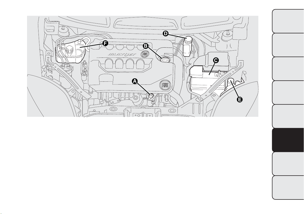
1.6 MultiJet version
A. Engine oil dipstick B. Engine oil cap/filler C. Battery D. Brake fluid E. washer fluid for windscreen/rear window/
headlights F. Engine coolant
fig. 176
F0Q0767
207
GETTING TO KNOW
YOUR CAR
SAFETY
STARTING AND
DRIVING
WARNING LIGHTS
AND MESSAGES
IN AN EMERGENCY
SERVICING AND
MAINTENANCE
TECHNICAL
SPECIFICATIONS
INDEX
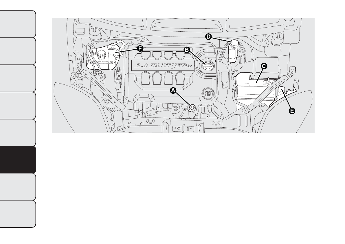
2.0 MultiJet version (for versions/markets, where provided)
A. Engine oil dipstick B. Engine oil cap/filler C. Battery D. Brake fluid E. washer fluid for windscreen/rear window/
headlights F. Engine coolant
fig. 177
F0Q0768
208
GETTING TO KNOW
YOUR CAR
SAFETY
STARTING AND
DRIVING
WARNING LIGHTS
AND MESSAGES
IN AN EMERGENCY
SERVICING AND
MAINTENANCE
TECHNICAL
SPECIFICATIONS
INDEX
ENGINE OIL
Engine oil level check
Check the oil level a few minutes (about five) after
the engine has stopped, with the vehicle parked
on level ground.
Take out engine oil dipstick A, clean it and then fully
reinsert it, take it out and check that the level is
between the MIN and MAX marks on the dipstick.
The range between the MIN and MAX marks
corresponds to approximately 1 litre of oil.
Topping up the engine oil
If the level of the oil is close to or below the MIN
mark, add oil via filler B until the MAX mark is
reached.
IMPORTANT If the engine oil level after the check is
over the MAX level, go to a Fiat Dealership to
have the correct level restored.
IMPORTANT After adding or changing the oil, let the
engine run for a few seconds and wait a few minutes
after switching it off before checking the level.
Engine oil consumption
The maximum engine oil consumption is
approximately 400 grams every 1,000 km.
During the initial period of usage for the vehicle, the
engine is bedding in, therefore the engine oil
consumption may settle down only after the first
5,000 - 6,000 km.
IMPORTANT The oil consumption depends on
driving style and the conditions under which the car
is used.
IMPORTANT Do not add oil with specifications
other than those of the oil already in the engine.
WARNING
When the engine is hot, take care when
working inside the engine compartment
to avoid burns. Remember that the fan may
start up if the engine is hot: this could injure
you. Make sure that scarves, ties and other
loose fitting garments do not get caught up in
moving parts.
Used engine oil and oil filters contain
substances which are harmful to the
environment.To change the oil and fil ters,
we advise you to contact a Fiat Dealership.
209
GETTING TO KNOW
YOUR CAR
SAFETY
STARTING AND
DRIVING
WARNING LIGHTS
AND MESSAGES
IN AN EMERGENCY
SERVICING AND
MAINTENANCE
TECHNICAL
SPECIFICATIONS
INDEX
BRAKE FLUID
Check that the liquid is at the maximum level (the
fluid level in the reservoir must not exceed the MAX
mark).
If the fluid level in the tank is too low, undo reservoir
cap D (see previous pages) and add the fluid
described in the chapter "Technical Specifications".
Note Carefully clean the cap of the reservoir and
the surrounding surface.
Take great care to ensure that impurities do not
enter the reservoir when the cap is opened.
For topping-up, always use a funnel with integrated
filter with mesh equal to or lower than 0.12 mm.
IMPORTANT Brake fluid is hygroscopic (i.e. it
absorbs moisture). For this reason, if the car is
mainly used in areas with a high degree of
atmospheric humidity, the fluid should be replaced at
more frequent intervals than specified in the
“Scheduled Servicing Plan”.
Prevent brake fluid, which is highly
corrosive, from coming into contact with
painted parts. Should it happen,
immediately wash with water.
WARNING
Brake fluid is poisonous and highly
corrosive. If contact accidentally occurs,
immediately wash the affected areas with
water and a neutral detergent, and then rinse
thoroughly with water. Call a doctor
immediately if swallowed.
WARNING
The symbol
on the container indicates
a synthetic brake fluid, which is
different from a mineral fluid. Using a
mineral-t ype fluid will damage the special
rubber seals of the braking system beyond
repair.
210
GETTING TO KNOW
YOUR CAR
SAFETY
STARTING AND
DRIVING
WARNING LIGHTS
AND MESSAGES
IN AN EMERGENCY
SERVICING AND
MAINTENANCE
TECHNICAL
SPECIFICATIONS
INDEX
WASHER FLUID FOR WINDSCREEN/
REAR WINDOW/HEADLIGHTS
If the level is too low, raise reservoir cap E (see
previous pages) and add the fluid described in the
chapter "Technical Specifications".
WARNING
Do not travel with the windscreen
washer reservoir empty: t he windscreen
washer is essential for improving visibility. Some
commercial windscreen washer additives are
flammable.The engine compartment contains
hot components which may set it on fire.
ENGINE COOLANT
The coolant level must be checked when the engine
is cold and must range between the MIN and MAX
marks on the reservoir.
If the level is too low, undo reservoir cap F (see
previous pages) and add the fluid described in the
chapter "Technical Specifications".
PARAFLU
UP
antifreeze is used in the
engine cooling system. Use the same fluid
as in the cooling system when topping
up. PARAFLU
UP
cannot be mixed with any other
type of fluid. If this happens, do not start the
engine; contact a Fiat Dealership.
WARNING
The cooling system is pressurised. If
necessary, replace the cap with another
of equivalent quality and the same
specifications as the original, otherwise the
efficiency of the system may be adversely
affected. Do not remove the reservoir cap when
the engine is hot: you risk scalding yourself.
211
GETTING TO KNOW
YOUR CAR
SAFETY
STARTING AND
DRIVING
WARNING LIGHTS
AND MESSAGES
IN AN EMERGENCY
SERVICING AND
MAINTENANCE
TECHNICAL
SPECIFICATIONS
INDEX

AIR CLEANER/POLLEN
FILTER/DIESEL FILTER
For filter replacement, contact a Fiat Dealership.
BATTERY
The battery does not require the electrolyte to be
topped up with distilled water. A periodic check,
which can be carried out at a Fiat Dealership is,
however, necessary to check efficiency.
REPLACINGTHE BATTERY
If necessary, replace the battery with another of
equivalent quality and the same specifications as the
original. Follow the battery manufacturer’s
instructions for maintenance.
USEFUL ADVICE FOR EXTENDING THE
LIFE OFYOUR BATTERY
To avoid draining your battery and make it last
longer, observe the following instructions:
❒ when you park the car, ensure that the doors,
tailgate and bonnet are closed properly, to prevent
any roof lights from remaining on inside the
passenger's compartment;
❒ switch off the internal roof lights. The car is,
however, equipped with a system which switches
the interior lights off automatically;
❒ do not keep accessories (e.g. sound system, hazard
lights, etc.) switched on for a long time when the
engine is not running;
❒ before performing any operation on the electrical
system, disconnect the negative battery cable;
❒ completely tighten the battery terminals.
212
GETTING TO KNOW
YOUR CAR
SAFETY
STARTING AND
DRIVING
WARNING LIGHTS
AND MESSAGES
IN AN EMERGENCY
SERVICING AND
MAINTENANCE
TECHNICAL
SPECIFICATIONS
INDEX
IMPORTANT If the charge level remains under 50%
for a long time, the battery is damaged by sulphation,
reducing its capacity and efficiency at start-up.
The battery will also be more at risk of freezing (this
can happen as early as -10°C). Refer to the paragraph
"Car inactivity" in "Starting and driving" if the car is
left parked for a long time.
If, after buying the car, you wish to install electrical
accessories which require permanent electrical
supply (alarm, etc.) or accessories which influence
the electrical supply requirements, contact a Fiat
Dealership, whose qualified staff will evaluate the
overall electrical consumption.
WARNING
Battery fluid is poisonous and corrosive.
Avoid contact with the skin and eyes.
Keep open flames away from the battery and
do not use objects t hat might create sparks: risk
of explosion and fire.
WARNING
Using the battery with insufficient fluid
irreparably damages the battery and
may cause an explosion.
Incorrect installation of electrical and
electronic devices may cause severe
damage to your car.After purchasing your
car, if you wish to install any accessories
(anti-theft, car phone, etc.), contact a Fiat
Dealership, which will suggest the most
appropriate devices for your vehicle, and will,
most importantly, advise you if a higher capacity
battery needs to be installed.
Batteries contain substances which are
very dangerous for the environment. For
battery replacement, contact a Fiat
Dealership.
213
GETTING TO KNOW
YOUR CAR
SAFETY
STARTING AND
DRIVING
WARNING LIGHTS
AND MESSAGES
IN AN EMERGENCY
SERVICING AND
MAINTENANCE
TECHNICAL
SPECIFICATIONS
INDEX
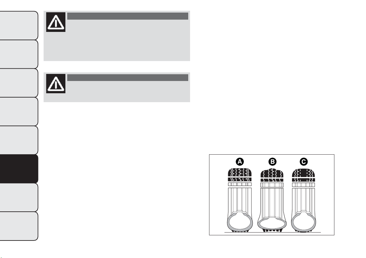
WARNING
If the car will be unused for an extended
period of time in extremely cold
weather conditions , remove the battery and
store it in a heated area to prevent it from
freezing.
WARNING
Always wear appropriate goggles when
working on or near the battery.
WHEELS AND TYRES
Before long trips, and every two weeks, check the
tyre and space-saver wheel inflation pressure (for
versions/markets, where provided). Check the tyres
when cold.
While driving the car, the pressure increases under
standard conditions: for the correct tyre inflation
pressure, see "Wheels" paragraph in the "Technical
specifications" chapter.
Incorrect pressure causes abnormal tyre wear
fig. 178:
A normal pressure: tread evenly worn;
B low pressure: tread particularly worn at the edges;
C high pressure: tread particularly worn in the
centre.
fig. 178
F0W0018
214
GETTING TO KNOW
YOUR CAR
SAFETY
STARTING AND
DRIVING
WARNING LIGHTS
AND MESSAGES
IN AN EMERGENCY
SERVICING AND
MAINTENANCE
TECHNICAL
SPECIFICATIONS
INDEX

The tyres must be replaced when the tread is less
than 1.6 mm thick. In any case, follow the laws
in force in the country where you are driving.
IMPORTANT
Take the following precautions to prevent damage to
the tyres:
❒ avoid braking suddenly, racing starts and violent
impact against the curb, potholes or other
obstacles and driving for extended periods on
uneven road surfaces;
❒ periodically check that the tyres have no cuts in
the side wall, abnormal swelling or irregular tyre
wear;
❒ avoid travelling with the car overloaded. If you
have a puncture, stop immediately and change the
tyre;
❒ tyres age even if they are not used much. Cracks in
the tread rubber and at the sides are a sign of
ageing. In any case, if the tyres have been on the
car for over 6 years, they should be checked
by specialised personnel. Also remember to check
the space-saver wheel very carefully (for
versions/markets, where provided);
❒ change the position of the tyres every 10-15
thousand kilometres, keeping them on the same
side of the car to avoid inverting the rotation
direction;
❒ In the case of replacement, always fit new tyres,
avoiding those of dubious origin;
❒ if a tyre is changed, also change the inflation valve.
WARNING
The road holding qualities of the car
also depend on the correct inflation
pressure of the tyres.
WARNING
If the pressure is too low the tyre
overheats and can be seriously
damaged.
215
GETTING TO KNOW
YOUR CAR
SAFETY
STARTING AND
DRIVING
WARNING LIGHTS
AND MESSAGES
IN AN EMERGENCY
SERVICING AND
MAINTENANCE
TECHNICAL
SPECIFICATIONS
INDEX
WARNING
Do not cross switch the tyres, moving
them from the right of the car to the
left and vice versa.
WARNING
Never submit alloy rims to repainting
treatments requiring t he use of
temperatures exceeding 150°C.The mechanical
properties of the wheels could be impaired.
WINDSCREEN/REAR WINDOW
WIPER
BLADES
Periodically clean the rubber part using special
products; TUTELA PROFESSIONAL SC 35 is
recommended.
Replace the blades if the rubber edge is deformed or
worn. In any case, it is advisable to replace them
approximately once a year. A few simple precautions
can reduce the possibility of damage to the blades:
❒ if the temperature falls below zero, make sure that
ice has not frozen the rubber against the glass. Use
an antifreeze product to release it if required;
❒ remove any snow from the glass: in addition to
protecting the blades, this prevents effort on
the motor and overheating;
❒ do not operate the windscreen/rear window
wipers on dry glass.
WARNING
Driving with worn windscreen/rear
window wiper blades is a serious hazard,
because visibility is reduced in bad weather.
216
GETTING TO KNOW
YOUR CAR
SAFETY
STARTING AND
DRIVING
WARNING LIGHTS
AND MESSAGES
IN AN EMERGENCY
SERVICING AND
MAINTENANCE
TECHNICAL
SPECIFICATIONS
INDEX
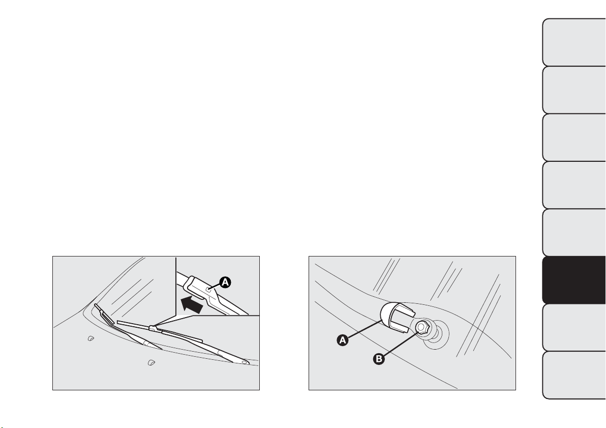
Replacing the wiper blades
Proceed as follows:
❒ lift up the windscreen wiper arm and position the
blade so that it forms a 90° angle with the arm;
❒ press tab A fig. 179 of the coupling spring and
remove the blade to be replaced from the arm;
❒ fit the new blade by inserting the tab into the
special slot in the arm. Make sure that the new
blade is secured in position.
Replacing the rear window wiper blade
Proceed as follows:
❒ raise cover A fig. 180 and remove the arm from
the car undoing the nut B that fastens it to the
pivot pin;
❒ correctly position the new arm and tighten the nut
fully;
❒ lower the cover.
fig. 179
F0Q0662
fig. 180
F0Q0663
217
GETTING TO KNOW
YOUR CAR
SAFETY
STARTING AND
DRIVING
WARNING LIGHTS
AND MESSAGES
IN AN EMERGENCY
SERVICING AND
MAINTENANCE
TECHNICAL
SPECIFICATIONS
INDEX
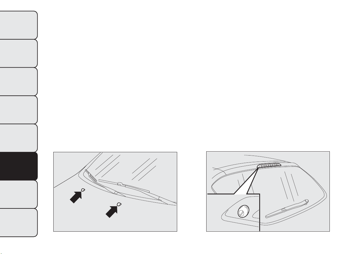
NOZZLES
Windscreen (washer)
If the jet is not coming out, firstly check that there is
fluid in the reservoir (see “Checking levels” in this
chapter). Then check that the nozzle holes, marked
by arrows in Fig. fig. 181, are not clogged; if
necessary use a needle. The window washer nozzles
are fixed.
Rear window (washer)
The rear window washer nozzles are fixed.
The nozzle holder is on the rear window fig. 182.
fig. 181
F0Q0661
fig. 182
F0Q0660
218
GETTING TO KNOW
YOUR CAR
SAFETY
STARTING AND
DRIVING
WARNING LIGHTS
AND MESSAGES
IN AN EMERGENCY
SERVICING AND
MAINTENANCE
TECHNICAL
SPECIFICATIONS
INDEX

BODYWORK
PROTECTION FROM ATMOSPHERIC
AGENTS
The main causes of corrosion are the following:
❒ atmospheric pollution
❒ salty air and humidity (coastal areas, or hot humid
climates);
❒ seasonal environmental conditions.
The abrasive action of wind-borne atmospheric dust
and sand, as well as mud and gravel raised by other
vehicles is also not to be underestimated.
On your car, Fiat has adopted the best manufacturing
technologies to effectively protect the bodywork
against corrosion.
These are the most important:
❒ Painting products and systems which give the car
particular resistance to corrosion and abrasion;
❒ Use of galvanised (or pretreated) steel sheets, with
high resistance to corrosion;
❒ spraying the underbody, engine compartment,
wheel arch interiors and other parts with highly
protective wax products;
❒ spraying of plastic parts, with a protective function
in the more exposed points: underdoor, inner
wing, edges, etc;
❒ Use of “open” boxed sections to prevent
condensation and pockets of moisture from
triggering rust inside.
BODY AND UNDERBODY WARRANTY
Your car is covered by warranty against perforation
due to rust of any original element of the structure
or body.
For the general terms of this warranty, refer to the
Warranty Booklet.
219
GETTING TO KNOW
YOUR CAR
SAFETY
STARTING AND
DRIVING
WARNING LIGHTS
AND MESSAGES
IN AN EMERGENCY
SERVICING AND
MAINTENANCE
TECHNICAL
SPECIFICATIONS
INDEX

ADVICE FOR PRESERVING THE
BODYWORK
Paint
Paintwork does not only serve an aesthetic purpose,
but also protects the underlying sheet metal.
Touch up abrasions and scratches immediately to
prevent rust formation. Use only original paint
products for touch-ups (see “Bodywork paint
identification plate” in the “Technical specifications”
section).
Normal maintenance of paintwork consists in
washing the car: the frequency depends on the
conditions and environment where the car is used.
For example, in highly polluted areas, or if the roads
are spread with salt, it is advisable to wash the car
more frequently.
To correctly wash the vehicle, proceed as follows:
❒ remove the aerial from the roof to prevent damage
to it if the car is washed in an automatic system;
❒ if high pressure jets or cleaners are used to wash
the vehicle, keep a distance of at least 40 cm
from the bodywork to avoid damage or alteration.
It should be remembered that the build up of
water can damage the car over a period of time;
❒ wash the body using a low pressure jet of water;
❒ wipe a sponge with a slightly soapy solution over
the bodywork, frequently rinsing with the sponge;
❒ rinse well with water and dry with a jet of air or a
chamois leather.
Dry the less visible parts particularly carefully, such
as the door frames, bonnet and the headlight frames,
where water may stagnate more easily. The car
should not be taken to a closed area immediately,
but left outside so that residual water can evaporate.
Do not wash the car after it has been left in the
sun or with the bonnet hot: this may alter the shine
of the paintwork.
220
GETTING TO KNOW
YOUR CAR
SAFETY
STARTING AND
DRIVING
WARNING LIGHTS
AND MESSAGES
IN AN EMERGENCY
SERVICING AND
MAINTENANCE
TECHNICAL
SPECIFICATIONS
INDEX

External plastic parts must be cleaned in the same
way as the rest of the car.
Where possible, do not park under trees; the
resinous substance that many species release give the
paint a dull appearance and increase the possibility
of triggering rusting processes.
IMPORTANT Bird droppings must be washed off
immediately and thoroughly as the acid they contain
is particularly aggressive.
Detergents pollute the environment.
Therefore the engine compartment should
be washed in areas equipped for
collecting and purifying the liquid used in t he
washing process.
Glasses
To clean glasses, use specific window cleaner
products.
Also use clean cloths to avoid scratching the glass or
damaging the transparency.
IMPORTANT Wipe the rear window inside gently
with a cloth in the direction of the filaments to avoid
damaging the heating device.
Engine compartment
IMPORTANT The washing should take place with the
engine cold and the ignition key in the STOP
position. After the washing operation, make sure
that the various protections (e.g. rubber caps and
guards) have not been removed or damaged.
Front headlights
IMPORTANT Never use aromatic substances (e.g.
petrol) or ketenes (e.g. acetone) for cleaning the
plastic lenses of the front headlights.
221
GETTING TO KNOW
YOUR CAR
SAFETY
STARTING AND
DRIVING
WARNING LIGHTS
AND MESSAGES
IN AN EMERGENCY
SERVICING AND
MAINTENANCE
TECHNICAL
SPECIFICATIONS
INDEX

INTERIORS
Periodically check for water puddles under the mats
that could cause the panels to rust.
Replace the worn carpet mats, if present, with
genuine products and make sure they remain
securely fastened to the passenger compartment
carpet. It is not advisable to use non genuine mats
that could move whilst driving.
WARNING
Never use flammable products, such as
petrol ether or rectified petrol to clean
the inside of the car.The electrostatic charges
which are generated by rubbing during the
cleaning operation may cause a fire.
WARNING
Do not keep aerosol cans in the car:
they might explode.Aerosol cans must
not be exposed to a temperature exceeding
50°C.When the car is exposed to sunlight,
internal temperature can greatly exceed this
value.
SEATS AND FABRIC PARTS
Remove dust with a soft brush or a vacuum cleaner.
Rub the seats with a sponge and a solution of water
and mild soap.
222
GETTING TO KNOW
YOUR CAR
SAFETY
STARTING AND
DRIVING
WARNING LIGHTS
AND MESSAGES
IN AN EMERGENCY
SERVICING AND
MAINTENANCE
TECHNICAL
SPECIFICATIONS
INDEX

LEATHER SEATS
Remove the dry dirt with a buckskin or slightly damp
cloth, without exercising too much pressure.
Remove any liquid or grease stains using an
absorbent dry cloth, without rubbing. Then clean
with a soft cloth or buckskin cloth dampened with
water and neutral soap.
If the stain persists, use specific products and
observe the instructions carefully.
IMPORTANT Never use alcohol. Make sure that the
cleaning products used contain no alcohol or alcohol
derivatives, even in small quantities.
The fabric upholstery of your car has
been designed to wi thstand wear deriving
from common use of the car.You are
however recommended to avoid strong and/or
continuous scratching wi th clothing accessories
such as metal buckles , studs,Velcro fastenings and
the like, as these items cause stress of the cover
fabric that could lead to yarn breaking and
damage the upholstery.
PLASTIC AND COATED PARTS
Clean interior plastic parts with a damp cloth (if
possible made from microfibre), and a solution
of water and neutral, non-abrasive detergent. To
clean oily or persistent stains, use specific products
free from solvents and designed to maintain the
original appearance and colour of the components.
Remove any dust using a microfibre cloth, if
necessary moistened with water. The use of paper
tissues is not recommended as these may leave
residues.
IMPORTANT Never use alcohol, petrols and
derivatives to clean the instrument panel lens.
223
GETTING TO KNOW
YOUR CAR
SAFETY
STARTING AND
DRIVING
WARNING LIGHTS
AND MESSAGES
IN AN EMERGENCY
SERVICING AND
MAINTENANCE
TECHNICAL
SPECIFICATIONS
INDEX

LEATHER STEERING WHEEL/GEAR
KNOB/HANDBRAKE
These components must be cleaned with mild soap
and water only. Never use alcohol or alcohol-based
products.
Read the product label carefully before using specific
products for cleaning the interiors: make sure the
product does not contain alcohol or alcohol-based
substances.
If, when cleaning the windscreen with special
products, window cleaner accidentally drips onto the
leather of the steering wheel/gear lever knob/hand
brake, wipe away immediately and then wash the
affected area with mild soap and water.
IMPORTANT Be careful when using a steering wheel
lock device, where applicable, to avoid damaging
the leather upholstery by rubbing.
224
GETTING TO KNOW
YOUR CAR
SAFETY
STARTING AND
DRIVING
WARNING LIGHTS
AND MESSAGES
IN AN EMERGENCY
SERVICING AND
MAINTENANCE
TECHNICAL
SPECIFICATIONS
INDEX
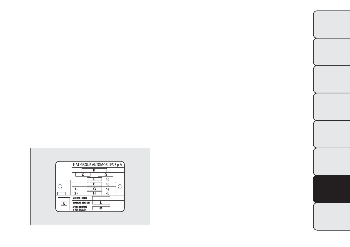
TECHNICAL SPECIFICATIONS
IDENTIFICATION DATA
The identification data of the car are:
❒ VIN plate;
❒ Chassis marking;
❒ Bodywork paint identification plate;
❒ Engine marking.
VIN PLATE
This plate is fitted to the engine compartment front
crossmember and contains the following data
fig. 183:
B
Type-approval number.
C
Vehicle type identification code.
D
Chassis serial number.
E
Maximum authorised weight of vehicle fully laden.
F
Maximum authorised weight of vehicle fully laden
plus trailer.
G
Maximum authorised weight on first (front) axle.
H
Maximum authorised weight on second (rear)
axle.
I
Engine type.
L
Bodywork version code.
M
Number for spare parts.
N
Correct value of smoke coefficient (for diesel
engines).
fig. 183
F0Q0029
225
GETTING TO KNOW
YOUR CAR
SAFETY
STARTING AND
DRIVING
WARNING LIGHTS
AND MESSAGES
IN AN EMERGENCY
SERVICING AND
MAINTENANCE
TECHNICAL
SPECIFICATIONS
INDEX
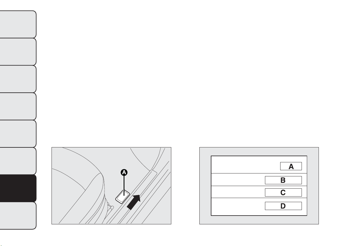
CHASSIS MARKING
This is printed on the passenger compartment floor,
near the front right seat.
Slide flap A fig. 184 forward to access:
The marking includes:
❒ car model (ZFA 198000);
❒ chassis serial number.
BODYWORK PAINT IDENTIFICATION
PLATE
This is fitted to the inside of the tailgate and bears
the following data fig. 185:
A Paint manufacturer.
B Colour name.
C Fiat colour code.
D Respray and touch up code.
ENGINE MARKING
This is stamped on the cylinder block and gives the
model and the chassis serial number.
fig. 184
F0Q0667
fig. 185
F0Q0100
226
GETTING TO KNOW
YOUR CAR
SAFETY
STARTING AND
DRIVING
WARNING LIGHTS
AND MESSAGES
IN AN EMERGENCY
SERVICING AND
MAINTENANCE
TECHNICAL
SPECIFICATIONS
INDEX
ENGINE CODE - BODYWORK VERSIONS
Versions Engine code Bodywork versions
1.6 MultiJet 105 HP 844A3000
198AXV1B 18
198AXV1B 18B
(*)
1.6 MultiJet 120 HP 198A2000
198AXL1B 08M
198AXL1B 08N
(*)
2.0 MultiJet 165 HP (**)
198A8000
198AXT1B 16
198AXT1B 16B
(*)
(*) Versions where 18" tyres can be fitted
(**) For versions/markets, where provided
227
GETTING TO KNOW
YOUR CAR
SAFETY
STARTING AND
DRIVING
WARNING LIGHTS
AND MESSAGES
IN AN EMERGENCY
SERVICING AND
MAINTENANCE
TECHNICAL
SPECIFICATIONS
INDEX
ENGINE
1.6 MultiJet 105 HP 1.6 MultiJet 120 HP
Type code 844A3000 198A2000
Cycle Diesel Diesel
Number and arrangement of cylinders 4 in line 4 in line
Piston bore and stroke (mm) 79.5 × 80.5 79.5 × 80.5
Total displacement (cm) 1598 1598
Compression ratio 16,5 16,5
Maximum power (EC) (kW) 77 88
Maximum power (EC) (HP) 105 120
corresponding engine speed (rpm) 4000 4000
Maximum torque (EC) (Nm) 300 300
Maximum torque (EC) (kgm) 30,6 30,6
corresponding engine speed (rpm) 1500 1500
Fuel Diesel for automotive engines (Specification EN590)
228
GETTING TO KNOW
YOUR CAR
SAFETY
STARTING AND
DRIVING
WARNING LIGHTS
AND MESSAGES
IN AN EMERGENCY
SERVICING AND
MAINTENANCE
TECHNICAL
SPECIFICATIONS
INDEX
2.0 MultiJet 165 HP (*)
Type code 198A8000
Cycle Diesel
Number and arrangement of cylinders 4 in line
Piston bore and stroke (mm) 83.0 x 90.4
Total displacement (cm) 1956
Compression ratio 16,5
Maximum power (EC) (kW) 121
Maximum power (EC) (HP) 165
corresponding engine speed (rpm) 4000
Maximum torque (EC) (Nm) 350
Maximum torque (EC) (kgm) 35,6
corresponding engine speed (rpm) 1750
Fuel Diesel for automotive engines (Specification EN590)
(*) For versions/markets, where provided
229
GETTING TO KNOW
YOUR CAR
SAFETY
STARTING AND
DRIVING
WARNING LIGHTS
AND MESSAGES
IN AN EMERGENCY
SERVICING AND
MAINTENANCE
TECHNICAL
SPECIFICATIONS
INDEX
FUEL SUPPLY
Versions Fuel supply
1.6 MultiJet - 2.0 MultiJet
Electronically controlled Common Rail MultiJet direct
injection with turbo and intercooler
WARNING
Modifications or repairs to the fuel supply system that are not carried out correctly or do not
take the system's technical specifications into account can cause malfunctions leading to
the risk of fire.
TRANSMISSION
Versions Gearbox Clutch Drive
1.6 MultiJet - 2.0 MultiJet
Six forward gears
plus reverse with
synchronisers for
forward gear
engagement
Self-adjusting with
pedal without idle
stroke
Front
230
GETTING TO KNOW
YOUR CAR
SAFETY
STARTING AND
DRIVING
WARNING LIGHTS
AND MESSAGES
IN AN EMERGENCY
SERVICING AND
MAINTENANCE
TECHNICAL
SPECIFICATIONS
INDEX

BRAKES
Versions
Front service
brakes
Rear service
brakes
Parking brake
1.6 MultiJet - 2.0 MultiJet Self-ventilated disc Disc
Controlled by hand
lever, acting on the
rear brakes
IMPORTANT Water, ice and salt spread on the roads may deposit on the brake discs reducing braking
efficiency the first time the brakes are applied.
SUSPENSION
Versions Front Rear
1.6 MultiJet - 2.0 MultiJet
MacPherson independent wheels
with anti-roll bar
Interconnected wheels with
torsion beam
231
GETTING TO KNOW
YOUR CAR
SAFETY
STARTING AND
DRIVING
WARNING LIGHTS
AND MESSAGES
IN AN EMERGENCY
SERVICING AND
MAINTENANCE
TECHNICAL
SPECIFICATIONS
INDEX
STEERING SYSTEM
Versions Type
Turning circle (kerb to kerb)
(m)
1.6 MultiJet - 2.0 MultiJet
Rack and pinion with electric
power steering
10.4 (11.0 with optional 18" alloy
rims)
232
GETTING TO KNOW
YOUR CAR
SAFETY
STARTING AND
DRIVING
WARNING LIGHTS
AND MESSAGES
IN AN EMERGENCY
SERVICING AND
MAINTENANCE
TECHNICAL
SPECIFICATIONS
INDEX

WHEELS
RIMS AND TYRES
Pressed steel or alloy rims. Tubeless radial carcass
tyres. The vehicle registration document also lists all
type-approved tyres.
IMPORTANT If there are any discrepancies between
the Owner Handbook and the registration
document, take the information from the latter. For
safe driving, the car must be fitted with tyres of
the same make and type on all wheels.
IMPORTANT Do not use air chambers with Tubeless
tyres.
SPARE WHEEL
Pressed steel rim. Tubeless tyre.
WHEEL GEOMETRY
Front wheel toe-in measured from rim to rim:
-1mm+/-1mm
The values refer to the car in running order.
CORRECT TYRE READING
Example fig. 186: 195/55 R 16 91V
195
Nominal width (S, distance in mm between
sidewalls)
55
Height/width ratio (H/S) as a percentage
R
Radial tyre
16
Rim diameter in inches (Ø)
91
Load rating (capacity)
V
Maximum speed rating
Maximum speed rating
Q
up to 160 km/h
R
up to 170 km/h
S
up to 180 km/h
T
up to 190 km/h
U
up to 200 km/h
H
up to 210 km/h
V
up to 240 km/h
W
up to 270 km/h
Y
up to 300 km/h
fig. 186
F0Q0200
233
GETTING TO KNOW
YOUR CAR
SAFETY
STARTING AND
DRIVING
WARNING LIGHTS
AND MESSAGES
IN AN EMERGENCY
SERVICING AND
MAINTENANCE
TECHNICAL
SPECIFICATIONS
INDEX
Maximum speed index for snow tyres
QM+S
up to 160 km/h
TM+S
up to 190 km/h
HM+S
up to 210 km/h
Load rating (capacity)
60 = 250 kg 84 = 500 kg
61 = 257 kg 85 = 515 kg
62 = 265 kg 86 = 530 kg
63 = 272 kg 87 = 545 kg
64 = 280 kg 88 = 560 kg
65 = 290 kg 89 = 580 kg
66 = 300 kg 90 = 600 kg
67 = 307 kg 91 = 615 kg
68 = 315 kg 92 = 630 kg
69 = 325 kg 93 = 650 kg
70 = 335 kg 94 = 670 kg
71 = 345 kg 95 = 690 kg
72 = 355 kg 96 = 710 kg
73 = 365 kg 97 = 730 kg
74 = 375 kg 98 = 750 kg
75 = 387 kg 99 = 775 kg
76 = 400 kg 100 = 800 kg
Load rating (capacity)
77 = 412 kg 101 = 825 kg
78 = 425 kg 102 = 850 kg
79 = 437 kg 103 = 875 kg
80 = 450 kg 104 = 900 kg
81 = 462 kg 105 = 925 kg
82 = 475 kg 106 = 950 kg
83 = 487 kg
CORRECT READING OF THE WHEEL RIM
Example fig. 186: 7Jx16ET31
7
rim diameter in inches (1).
J
rim drop centre outline (side projection where the
tyre bead rests) (2).
16
rim nominal diameter in inches (corresponds to
diameter of the tyre to be mounted) (3 = Ø).
H2
shape and number of humps (circumference
measurement which keeps the bead of Tubeless
tyres in position on the rim).
ET 31
wheel camber (distance between the disc/rim
support plane and the wheel centre line).
234
GETTING TO KNOW
YOUR CAR
SAFETY
STARTING AND
DRIVING
WARNING LIGHTS
AND MESSAGES
IN AN EMERGENCY
SERVICING AND
MAINTENANCE
TECHNICAL
SPECIFICATIONS
INDEX

RIMS AND TYRES PROVIDED AS STANDARD
Version Rims Tyres Snow tyres
Spare wheel
Rim Tyre
1.6 MultiJet
105 HP
6J x 15 ET 31.5
(**)
195/65 R15 91H
(**)
195/65 R15 91T
(M+S)
(**)
(***) (***)
7J x 16 ET 31 205/55 R16 91H
205/55 R16 91T
(M+S)
7J x 17 ET 26 225/45 R17 91W
225/45 R17 91T
(M+S)
7Jx16ET31
205/55 R16 91H
205/55 R16 91V
(****)
7J x 17 ET 31 225/45 R17 91W
225/45 R17 91T
(M+S)
71/2Jx18ET35
225/40 R18 92V
REINFORCED
(*****)
225/40 R18 92T
(M+S)
(**) For versions/markets, where provided
(***) On versions equipped with 195/65 R15 and 205/55 R16 tyres, a normal sized tyre may be ordered as an alternative to the
Fix&Go.
(****) The 205/55 R16 91H (or 205/55 R16 91V) tyre has the same specifications as the space-saver wheel: the information in the
“Replacing a wheel” paragraph therefore refers to the 205/55 R16 91H (or 205/55 R16 91V) tyre.
(*****) Tyres which cannot be fitted with chains.
235
GETTING TO KNOW
YOUR CAR
SAFETY
STARTING AND
DRIVING
WARNING LIGHTS
AND MESSAGES
IN AN EMERGENCY
SERVICING AND
MAINTENANCE
TECHNICAL
SPECIFICATIONS
INDEX

Version Rims Tyres Snow tyres
Spare wheel
Rim Tyre
1.6 MultiJet
120 HP
7J x 16 ET 31 195/55 R16 91V
195/55 R16 91T
(M+S)
(***) (***)
7J x 16 ET 31 205/55 R16 91V
205/55 R16 91T
(M+S)
7J x 17 ET 31 225/45 R17 91W
225/45 R17 91T
(M+S)
7Jx16ET31
205/55 R16 91H
205/55 R16 91V
(****)
71/2Jx18ET35
225/40 R18 92W
REINFORCED
(*****)
225/40 R18 92T
(M+S)
(***) On versions equipped with 195/55 R16 and 205/55 R16 tyres, a normal sized tyre may be ordered as an alternative to the
Fix&Go.
(****) The 205/55 R16 91H (or 205/55 R16 91V) tyre has the same specifications as the space-saver wheel: the information in the
“Replacing a wheel” paragraph therefore refers to the 205/55 R16 91H (or 205/55 R16 91V) tyre.
(*****) Tyres which cannot be fitted with chains.
236
GETTING TO KNOW
YOUR CAR
SAFETY
STARTING AND
DRIVING
WARNING LIGHTS
AND MESSAGES
IN AN EMERGENCY
SERVICING AND
MAINTENANCE
TECHNICAL
SPECIFICATIONS
INDEX
Version Rims Tyres Snow tyres
Spare wheel
Rim Tyre
2.0 MultiJet
165 HP
7J x 16 ET 31 195/55 R16 91V
195/55 R16 91T
(M+S)
(***) (***)
7J x 16 ET 31 205/55 R16 91V
205/55 R16 91T
(M+S)
7J x 17 ET 26 225/45 R17 91W
225/45 R17 91T
(M+S)
7Jx16ET31
205/55 R16 91H
205/55 R16 91V
(****)
7J x 17 ET 31 225/45 R17 91W
225/45 R17 91T
(M+S)
71/2Jx18ET35
225/40 R18 92W
REINFORCED
(*****)
225/40 R18 92T
(M+S)
(***) On versions equipped with 195/55 R16 and 205/55 R16 tyres, a normal sized tyre may be ordered as an alternative to the
Fix&Go.
(****) The 205/55 R16 91H (or 205/55 R16 91V) tyre has the same specifications as the space-saver wheel: the information in the
“Replacing a wheel” paragraph therefore refers to the 205/55 R16 91H (or 205/55 R16 91V) tyre.
(*****) Tyres which cannot be fitted with chains.
SPACE-SAVER WHEEL (for versions/markets, where provided)
Rim: 4B x 15H ET 35
Tyre: T125/90 R15 96M
IMPORTANT Special techniques need to be adopted for 225/40 R18 92W tyres. For this reason, these tyres
can only be requested when the vehicle is purchased. Do not fit this tyre after the vehicle has been
purchased!
237
GETTING TO KNOW
YOUR CAR
SAFETY
STARTING AND
DRIVING
WARNING LIGHTS
AND MESSAGES
IN AN EMERGENCY
SERVICING AND
MAINTENANCE
TECHNICAL
SPECIFICATIONS
INDEX
TYRE INFLATION PRESSURE WHEN COLD (bar)
Ty res
Unladen/medium load Full load
Space-saver
wheel
(*)
Front Rear Front Rear
195/65 R15 91H
(*)
2,3 2,3 2,6 2,6
4,2
195/55 R16 91V 2,3 2,3 2,6 2,6
205/55 R16 91H 2.3 2.3 2.6 2.6
205/55 R16 91V 2.3 2.3 2.6 2.6
225/45 R17 91W 2.3 2.3 2.6 2.6
225/40 R18 92W 2,6 2,6 2,9 2,9
(*) For versions/markets, where provided
Add +0.3 bar to the prescribed pressure when the
tyres are warm.
Recheck pressure value with cold tyres. With snow
tyres, add +0.2 bar to the pressure value prescribed
for standard tyres.
When travelling at speeds above 160 km/h, inflate
the tyres to the values specified for fully laden
conditions.
238
GETTING TO KNOW
YOUR CAR
SAFETY
STARTING AND
DRIVING
WARNING LIGHTS
AND MESSAGES
IN AN EMERGENCY
SERVICING AND
MAINTENANCE
TECHNICAL
SPECIFICATIONS
INDEX
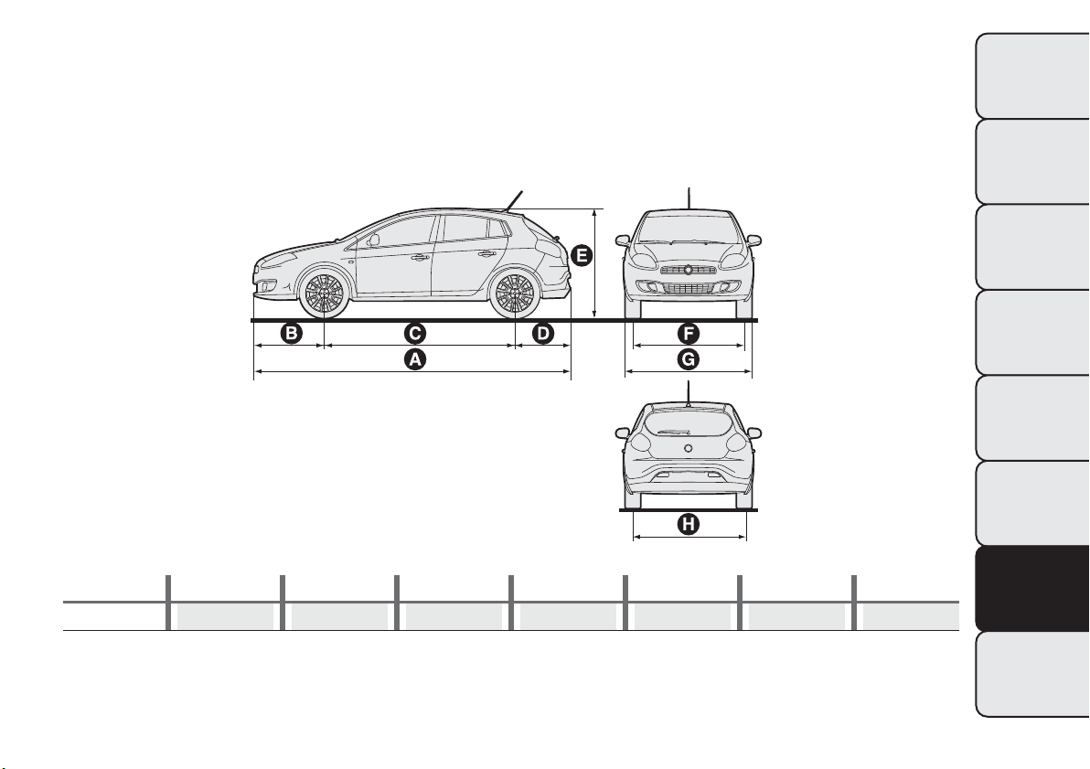
DIMENSIONS
Dimensions are expressed in mm fig. 187 and refer to the vehicle equipped with its original tyres. Height is
measured with car unladen.
LUGGAGE COMPARTMENT CAPACITY Capacity with car unladen (VDA standards): 400 dm
3
with
cargo box (for versions/markets, where provided). Capacity with rear seat backrest folded down: 1175 dm
3
with cargo box (for versions/markets, where provided).
ABCDE
F
(*)
G
H
(*)
4336 974 2600 762 1498 1538 1792 1532
(*) Small variations in size are possible depending on the dimensions of the rims.
fig. 187
F0Q0003
239
GETTING TO KNOW
YOUR CAR
SAFETY
STARTING AND
DRIVING
WARNING LIGHTS
AND MESSAGES
IN AN EMERGENCY
SERVICING AND
MAINTENANCE
TECHNICAL
SPECIFICATIONS
INDEX
PERFORMANCE
Max. speed in km/h that can be reached after initial car use.
Versions km/h
1.6 MultiJet 105 HP
187
(*)
1.6 MultiJet 120 HP 194
2.0 MultiJet 165 HP
(**)
215
(*) Top speed in sixth gear
(**) For versions/markets, where provided
240
GETTING TO KNOW
YOUR CAR
SAFETY
STARTING AND
DRIVING
WARNING LIGHTS
AND MESSAGES
IN AN EMERGENCY
SERVICING AND
MAINTENANCE
TECHNICAL
SPECIFICATIONS
INDEX
WEIGHTS
Weights (kg) 1.6 MultiJet
2.0 MultiJet
(*)
Unladen weight (with all fluids, fuel tank filled
to 90% and without optional equipment)
1320 1360
Payload including the driver:
(**)
510 510
Maximum permitted loads:
(***)
– front axle: 1060 1060
– rear axle: 860 860
– total: 1830 1870
Towable loads
- braked trailer: 1300 1300
- non-braked trailer: 500 500
Maximum load on roof:
(****)
80 80
Maximum load on ball joint (braked trailer): 60 60
(*) For versions/markets, where provided
(**) If special equipment is fitted (sun roof, tow hook, etc.) the unladen car weight increases, thus reducing the specified payload with
respect to the maximum permitted loads.
(***) Loads not to be exceeded. The user is responsible for arranging goods in the luggage compartment and/or load platform within
the maximum permitted loads.
(****) Lineaccessori Fiat roof rack bars, max capacity: 50 kg.
241
GETTING TO KNOW
YOUR CAR
SAFETY
STARTING AND
DRIVING
WARNING LIGHTS
AND MESSAGES
IN AN EMERGENCY
SERVICING AND
MAINTENANCE
TECHNICAL
SPECIFICATIONS
INDEX
REFUELLING
1.6 MultiJet 2.0 MultiJet (*)
Prescribed fuels and
original lubricants
Fuel tank (litres): 58 58
Diesel for motor vehicles
(EN 590 Specification)
including a reserve of
(litres):
8÷10 8÷10
Engine cooling system
(litres):
7,1 7,1
Mixture of demineralised
water and
50% PARAFLU
UP
(**)
Engine sump (litres): 4,3 4,3
SELENIA WR FORWARD
Engine sump and filter
(litres):
4,6 4,9
Gearbox/differential casing
(litres):
1,87 1,87
TUTELA TRANSMISSION
GEARFORCE
Hydraulic brake circuit with
ABS:
0,56 0,56 TUTELA TOP 4
Windscreen and rear
window washer fluid
reservoir (litres):
3 (6) 3 (6)
Mixture of water and
TUTELA PROFESSIONAL
SC35
(**) For particularly harsh climate conditions, a mixture of 60% PARAFLU
UP
and 40% demineralised water is recommended.
(*) For versions/markets, where provided
242
GETTING TO KNOW
YOUR CAR
SAFETY
STARTING AND
DRIVING
WARNING LIGHTS
AND MESSAGES
IN AN EMERGENCY
SERVICING AND
MAINTENANCE
TECHNICAL
SPECIFICATIONS
INDEX
FLUIDS AND LUBRICANTS
Your car is equipped with an engine oil that has been thoroughly developed and tested in order to meet the
requirements of the Scheduled Servicing Plan. Constant use of the prescribed lubricants guarantees the
fuel consumption and emission specifications. Lubricant quality is crucial for engine operation and duration.
PRODUCT SPECIFICATIONS
Use
Fluid and lubricant specifications for a
correct use of the car
Genuine fluids and
lubricants
Replacement interval
Lubricant for
diesel engines
SAE 0W-30 grade fully synthetic lubricant.
FIAT 9.55535-DS1, ACEA C2 classification.
SELENIA WR
FORWARD
Contractual Technical
Reference No. F842.F13
According to Scheduled
Servicing Plan
In case of emergency, if lubricants with the prescribed specifications are not available, products with the
minimum indicated ACEA performance can be used for topping up; in this case optimal performance of the
engine is not guaranteed.
The use of products with different specifications than those indicated above could cause
damage to the engine that is not covered by the warranty.
243
GETTING TO KNOW
YOUR CAR
SAFETY
STARTING AND
DRIVING
WARNING LIGHTS
AND MESSAGES
IN AN EMERGENCY
SERVICING AND
MAINTENANCE
TECHNICAL
SPECIFICATIONS
INDEX

Use
Fluid and lubricant specifications for a
correct use of the car
Genuine fluids and
lubricants
Applications
Lubricants and
greases for
drive
transmission
SAE 75W grade synthetic lubricant.
FIAT 9.55550-MZ6 classification
TUTELA
TRANSMISSION
GEARFORCE
Contractual Technical
Reference No. F002.F10
Manual gearboxes and
differentials
Molybdenum disulphide grease, for use at
high temperatures. NL.G.I. 1-2 consistency.
FIAT Classification 9.55580
TUTELA ALL STAR
Contractual Technical
Reference No.
F702.G07
Wheel side constant
velocity joints
Grease for constant velocity joints with low
friction coefficient. NL.G.I. 0-1 consistency.
FIAT Classification 9.55580
TUTELA STAR 700
Contractual Technical
Reference No.
F701.C07
Differential side constant
velocity joints
Brake fluid
Synthetic fluid for brake and clutch systems.
Exceeds specifications: FMVSS no. 116 DOT
4, ISO 4925 SAE J1704. FIAT Classification
9.55597
TUTELA TOP 4
Contractual Technical
Reference No.
F001.A93
Hydraulic brakes and
hydraulic clutch controls
244
GETTING TO KNOW
YOUR CAR
SAFETY
STARTING AND
DRIVING
WARNING LIGHTS
AND MESSAGES
IN AN EMERGENCY
SERVICING AND
MAINTENANCE
TECHNICAL
SPECIFICATIONS
INDEX

Use
Fluid and lubricant specifications for a
correct use of the car
Genuine fluids and
lubricants
Applications
Protective
agent for
radiators
Red protective agent with antifreeze action,
based on inhibited monoethylene glycol with
organic formula. Exceeds CUNA NC 956-16,
ASTM D 3306 specifications. FIAT 9.55523
classification
PARAFLU
UP
(*)
Contractual Technical
Reference No.
F101.M01
Cooling circuit usage
percentage: 50%
demineralised water
50% PARAFLU
UP
(**)
Additive for
diesel
Additive for diesel with antifreeze and
protective action for diesel engines
TUTELA
DIESEL ART
Contractual Technical
Reference No. F601.L06
To be mixed with diesel
(25 cc per 10 litres)
Windscreen/
rear window
washer fluid
Mixture of alcohols and surfactants. Exceeds
CUNA NC 956-11 specifications.
FIAT Classification 9.55522
TUTELA
PROFESSIONAL
SC 35
Contractual Technical
Reference No.
F201.D02
To be used diluted or
undiluted in windscreen/
rear window washer/wiper
systems
(*) IMPORTANT Do not use fluids with different specifications for topping up or mixing.
(**) For particularly harsh climate conditions, a mixture of 60% PARAFLU
UP
and 40% demineralised water is recommended.
245
GETTING TO KNOW
YOUR CAR
SAFETY
STARTING AND
DRIVING
WARNING LIGHTS
AND MESSAGES
IN AN EMERGENCY
SERVICING AND
MAINTENANCE
TECHNICAL
SPECIFICATIONS
INDEX
FUEL CONSUMPTION
The fuel consumption figures given in the table below are determined on the basis of the type-approval tests
laid down by specific European Directives.
The procedures below are followed for measuring consumption:
❒ urban cycle: cold starting followed by driving that simulates urban use of the car;
❒ extra-urban cycle: frequent accelerating in all gears, simulating extra-urban use of the car: speed varies
between 0 and 120 km/h;
❒ combined fuel consumption: calculated with a weighting of approximately 37% of the urban cycle and 63%
of the extra-urban cycle.
IMPORTANT The type of route, traffic conditions, weather conditions, driving style, general condition of the
car, trim level/equipment/accessories, use of the climate control system, car load, presence of roof racks
and other situations that adversely affect the aerodynamics or wind resistance lead to different fuel
consumption values than those measured.
FUEL CONSUMPTION ACCORDING TOTHE CURRENT EUROPEAN DIRECTIVE
(litres/100 km)
Versions Urban Extra-urban Combined
1.6 MultiJet 105 HP 5,3 3,7 4,3
1.6 MultiJet 120 HP 5,6 3,8 4,5
2.0 MultiJet
(*)
6,7 4,2 5,1
(*) For versions/markets, where provided
246
GETTING TO KNOW
YOUR CAR
SAFETY
STARTING AND
DRIVING
WARNING LIGHTS
AND MESSAGES
IN AN EMERGENCY
SERVICING AND
MAINTENANCE
TECHNICAL
SPECIFICATIONS
INDEX
CO
2
EMISSIONS
The CO
2
emission levels given in the following table refer to combined consumption.
Versions CO
2
emissions according to the current European directive (g/km)
1.6 MultiJet 105 HP 113
1.6 MultiJet 120 HP 117
2.0 MultiJet
(*)
135
(*) For versions/markets, where provided
247
GETTING TO KNOW
YOUR CAR
SAFETY
STARTING AND
DRIVING
WARNING LIGHTS
AND MESSAGES
IN AN EMERGENCY
SERVICING AND
MAINTENANCE
TECHNICAL
SPECIFICATIONS
INDEX
OFFICIAL TYPE APPROVALS
248
GETTING TO KNOW
YOUR CAR
SAFETY
STARTING AND
DRIVING
WARNING LIGHTS
AND MESSAGES
IN AN EMERGENCY
SERVICING AND
MAINTENANCE
TECHNICAL
SPECIFICATIONS
INDEX
249
GETTING TO KNOW
YOUR CAR
SAFETY
STARTING AND
DRIVING
WARNING LIGHTS
AND MESSAGES
IN AN EMERGENCY
SERVICING AND
MAINTENANCE
TECHNICAL
SPECIFICATIONS
INDEX

page intentionally left blank

DASHBOARD
The presence and the position of the instruments and warning lights may vary according to the versions.
1. Adjustable and swivel air vent - 2. Side window air vent - 3. Front passenger air bag - 4. Adjustable and swivel air vents
- 5. Hazard light switch - 6. External light stalk - 7. Instrument panel - 8. Windscreen/rear window wiper/trip computer
stalk - 9. Bonnet opening lever - 10. Glovebox - 11. Ignition key and ignition device - 12. Steering wheel locking/release
stalk - 13. Driver’s air bag - 14. Driver’s knees air bag (for versions/markets, where provided) - 15. Set of switches for
front/rear fog lights and menu opening/setting - 16. Controls for heating/ventilation/climate control - 17. Sound system
controls - 18. Set of ON/OFF switches for electric power steering and ASR system (for versions/markets, where
provided) - 19. Oddment compartment
fig. 1
F0Q0005
249
RIGHT HAND DRIVE VERSIONS
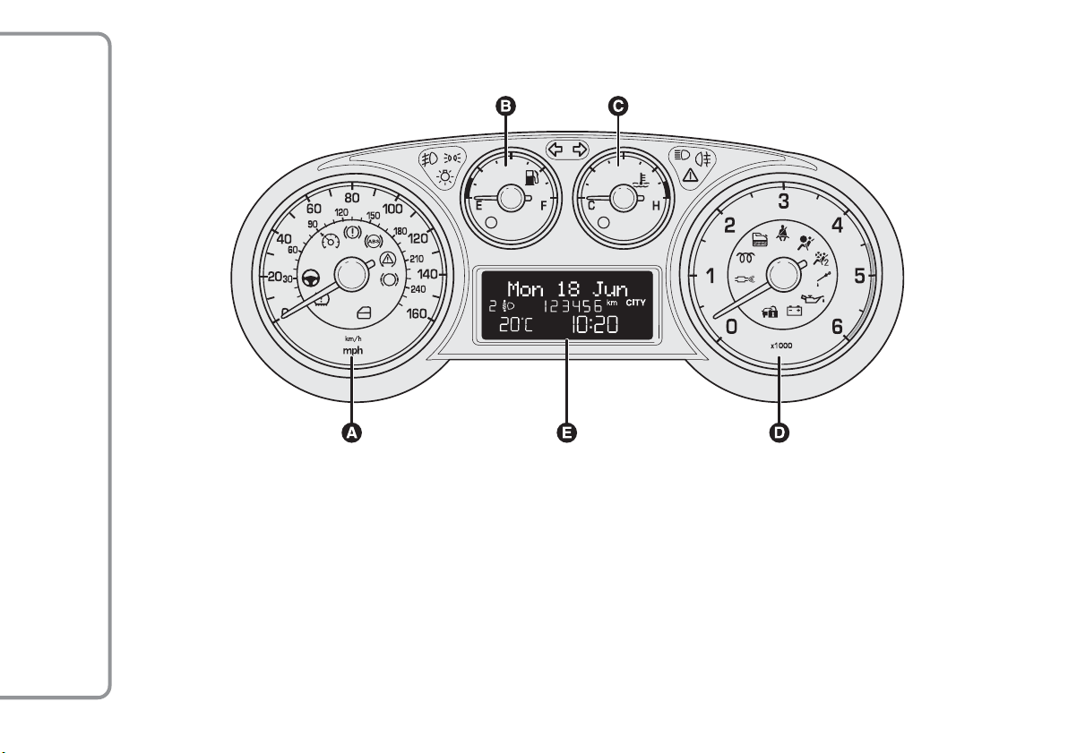
INSTRUMENT PANEL
A. Speedometer (speed indicator) B. Fuel level gauge with reserve warning light C. Engine coolant temperature gauge and
excessive temperature warning light D. Rev counter E. Display
fig. 2
F0Q0911
250
RIGHT HAND DRIVE VERSIONS
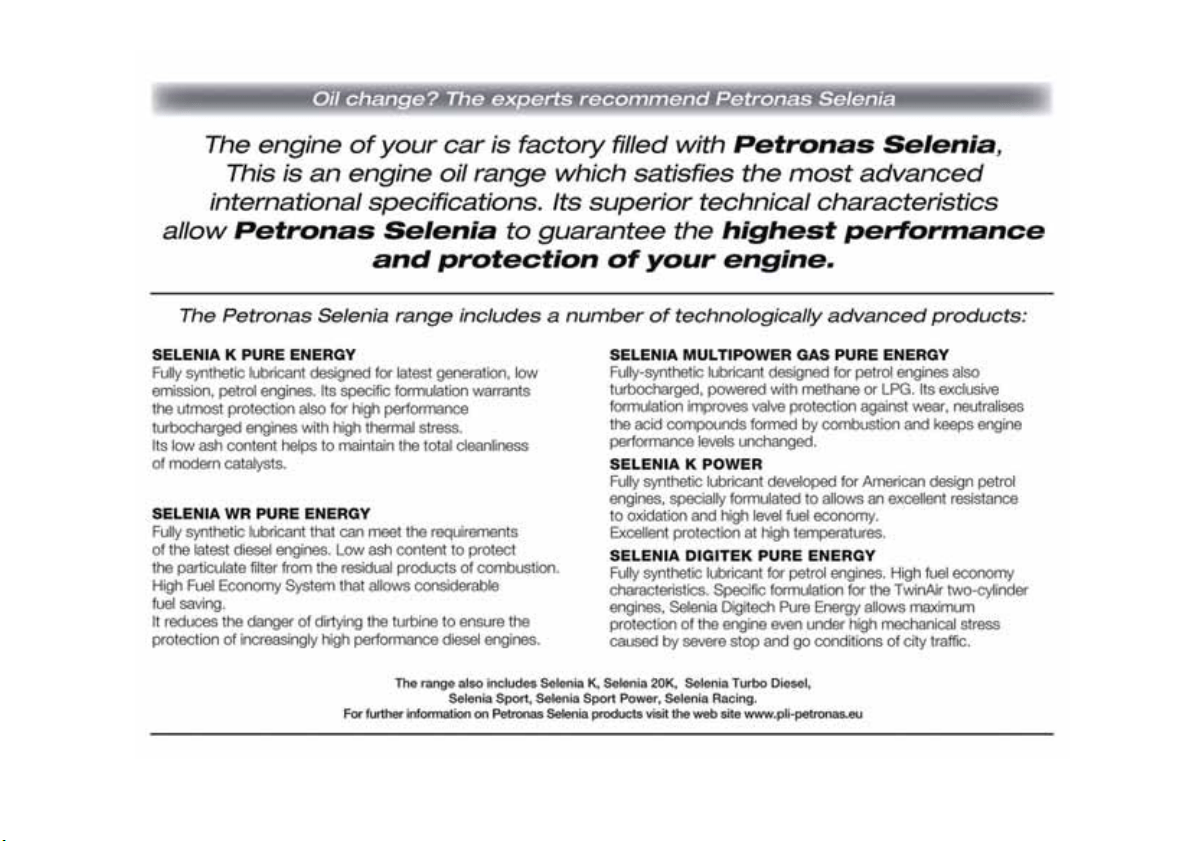

NOTES


INDEX
ABS (system) .............................. 89
Accessories purchased by
the owner................................... 96
Activation/Deactivation
(CITY function)......................... 97
Activation of internal air
recirculation and
enablement of AQS
function (Air Quality
System)........................................ 49
Additional heater ............. 41-45-51
Adjustable side vents and
diffusers....................................... 37
Air cleaner................................... 212
Air distribution selection.......... 50
Alarm............................................. 14
Anti-pinch safety device ............ 74
Ashtray.......................................... 70
ASR (system) ............................... 93
Automatic dual zone climate
control system .......................... 46
Automatic headlight sensor
(dusk sensor)............................. 54
Automatic operation of the
climate control system
(AUTO function) ...................... 47
Battery ........................................ 212
– advice for extending
lifetime.................................... 212
– replacement........................... 212
Battery (recharging) .................. 198
Bodywork
– maintenance .......................... 220
– protection against
atmospheric agents.............. 219
– warranty................................. 219
Bonnet........................................... 85
Brake Assist ................................. 91
Brake fluid.................................... 210
Brakes
– specifications ......................... 231
ulb replacement............... 180-182
Bulb replacement
– exterior lights ....................... 177
– interior lights......................... 184
Bulbs
– bulbs (replacement)............. 174
– general instructions ............. 174
– types of bulbs........................ 175
Capacities.................................... 242
Car dimensions .......................... 239
Cargo Box .................................... 85
Carrying children safely............ 116
– child restraint systems ........ 124
– "Isofix" child restraint
system setup ......................... 122
Central diffusers ......................... 37
Central locking............................ 75
Changing a wheel....................... 162
Checking fluid levels.................. 206
Child lock device ........................ 75
Child restraint systems
(compliance for use) ............... 121
Cigar lighter ................................. 69
Cleaning and maintenance
– bodywork............................... 219
– car interior............................. 222
– engine compartment ........... 221
– front headlights..................... 221
– Plastic and coated parts...... 223
– seats................................ 222-223
– windows ................................. 221
Climate control/heating
system ......................................... 36
265
GETTING TO KNOW
YOUR CAR
SAFETY
STARTING AND
DRIVING
WARNING LIGHTS
AND MESSAGES
IN AN EMERGENCY
SERVICING AND
MAINTENANCE
TECHNICAL
SPECIFICATIONS
INDEX
B

Climate control system
compressor
activation/deactivation............. 50
Clutch........................................... 230
CO2 emissions........................... 247
CODE Card................................. 8
Control buttons (display) ......... 18
Control panel and
instruments ................................ 4
Controls................. 39-42-47-63-78
Courtesy mirror lights
– bulb replacement.................. 187
Cruise Control............................ 59
Dashboard ................................... 3
Description .................................. 47
Diesel filter.................................. 212
Diffusers........................................ 37
Dipped headlights....................... 52
– bulb replacement.................. 177
Direction indicators................... 53
– bulb replacement.................. 179
Display........................................... 17
Door mirrors............................... 34
Doors ............................................ 75
DPF (Diesel Particulate
Filter).......................................... 109
Driver front airbag .................... 127
Driver's side knee bag .............. 130
"Dualdrive" electric power
steering system......................... 97
EBD (system).............................. 90
Electric windows......................... 77
Emergency manoeuvre.............. 74
Engine code - bodywork
versions...................................... 227
Engine compartment
– opening/closing ...................... 85
– washing ................................... 221
Engine coolant............................ 211
Engine coolant temperature
indicator...................................... 6
Engine
– marking................................... 226
– technical data ........................ 228
Engine oil
– Consumption ........................ 209
– Level check ............................ 209
– specifications ......................... 243
EOBD system.............................. 95
ESP (system) ................................ 91
ESP system ................................... 91
Exterior lights.............................. 52
Failure indications...................... 98
Fan speed adjustment ..... 41-44-48
Fast front window
demisting/defrosting............ 40-43
Fiat CODE (system) .................. 7
Fiat CODE system ..................... 7
Fitting "Universal" child
restraint system ....................... 118
Fix&Go Automatic Kit ............. 169
Flashing.......................................... 52
Fluids and lubricants
(specifications).......................... 243
Fog lights................................ 63-180
"Follow me home" device........ 53
Front airbags.............................. 126
Front armrest .............................. 66
Front light clusters
(changing a bulb) ...................... 177
Front roof light
– bulb replacement.................. 184
Front roof light with spot
lights............................................. 61
Fuel cut-off switch...................... 64
Fuel cut-off system..................... 65
Fuel
– saving fuel............................... 139
266
GETTING TO KNOW
YOUR CAR
SAFETY
STARTING AND
DRIVING
WARNING LIGHTS
AND MESSAGES
IN AN EMERGENCY
SERVICING AND
MAINTENANCE
TECHNICAL
SPECIFICATIONS
INDEX

Fuel level gauge ........................... 5
Fuel supply................................... 230
Fuse boxes (location)................ 188
Fuses
– dashboard fuse box.............. 189
– engine compartment fuse
box next to the battery ............
190-191
– fuse list.................................... 193
– luggage compartment
fuse box.................................. 192
– replacing fuses....................... 187
G Holder........................... 70
Glove compartment light
– bulb replacement.................. 186
Handbrake.................................. 137
Hazard warning lights ................ 63
Headlight alignment
corrector .................................... 88
Headlights..................................... 88
– bulb replacement.................. 177
Headlight washers ...................... 58
Head restraints............................ 31
Heated rear window and
door mirrors
demisting/defrosting...... 40-44-48
Heating and ventilation ............. 39
Hill Holder (system) .................. 92
Identification data
– bodywork paint plate .......... 226
– chassis marking ..................... 226
– engine marking...................... 226
– identification data plate ...... 225
Ignition switch ............................. 16
Initialisation procedure.............. 74
Installing
electrical/electronic devices... 96
Installing the tow hook............. 142
Interior fittings ............................ 66
Interiors (cleaning) .................... 222
Internal air recirculation
activation................................ 41-44
Internal mirror............................. 34
Jack ............................................... 164
Key without remote
control ........................................ 8
Key with remote control .......... 9
Light clusters
– rear light clusters
(changing a bulb)................... 181
Lights off ....................................... 52
Load limiters ............................... 113
Luggage compartment............... 80
– Extending ................................ 81
– Opening................................... 80
– Securing your load ................ 84
Luggage compartment roof
light
– bulb replacement.................. 186
Main beam headlights ............... 52
– bulb replacement.................. 179
Maintenance and care
– Scheduled servicing.............. 202
– scheduled servicing plan ..... 203
Manual climate control
system ......................................... 42
Menu items................................... 20
MSR system.................................. 93
MSR (system)............................... 93
Number plate lights
– bulb replacement.................. 183
Parking......................................... 137
Parking lights................................ 52
Parking sensors .......................... 103
Passenger compartment
heating .................................... 40-43
Passenger front airbag .............. 127
Performance (top speed)......... 240
267
GETTING TO KNOW
YOUR CAR
SAFETY
STARTING AND
DRIVING
WARNING LIGHTS
AND MESSAGES
IN AN EMERGENCY
SERVICING AND
MAINTENANCE
TECHNICAL
SPECIFICATIONS
INDEX
lass

Pollen filter.................................. 212
Power socket............................... 69
Pretensioners.............................. 113
Protecting the environment.... 109
Rain sensor.................................. 56
Raising the car ............................ 199
Rapid front window
demisting/defrosting
(MAX-DEF function) ............... 48
Rear armrest................................ 67
Rear diffuser................................. 38
Rear door emergency
locking device ............................ 76
Rear fog light......................... 63-182
Rear roof light ............................. 62
– bulb replacement.................. 185
Rear view mirrors....................... 34
Rear window washer
nozzles........................................ 218
Rear window washer/wiper ..... 57
Rear window wiper
– blade replacement................ 217
– blades ...................................... 216
Refuelling the car ....................... 107
Replacing fuses............................ 187
Replacing the battery in the
key with remote control......... 11
Replacing the remote
control cover............................. 11
Rev counter.................................. 5
Reverse light................................ 182
Rims and tyres............................ 233
Rims
– wheels and tyres................... 214
Roof lights .................................... 61
Roof rack/ski rack....................... 87
Safe lock (device)....................... 12
Safety
– carrying children safely........ 116
Saving fuel .................................... 139
SBR system.................................. 112
Scheduled Servicing Plan .......... 203
Seat belts ..................................... 110
– load limiters........................... 113
– maintenance .......................... 116
– pretensioners ........................ 113
Seats............................................... 30
– Backrest angle
adjustment.............................. 30
– Height adjustment................. 30
– Longitudinal adjustment ...... 30
– Lumbar adjustment............... 30
Servicing and care
– heavy-duty use of the car... 205
– periodic checks..................... 205
Set temperature alignment
(MONO function) .................... 50
Setup menu (display).................. 19
Side airbags (side bag -
window bag).............................. 131
Side bags ...................................... 131
Side lights...................................... 52
– bulb replacement.................. 178
Snow chains................................. 144
Snow tyres................................... 143
Spark plugs (type) ...................... 228
Speedometer ............................... 5
Starting the engine............ 135-161
Steering lock ................................ 16
Steering system .......................... 232
Steering wheel............................. 33
Storage compartments ......... 68-70
Storing the car............................ 145
Sun roof ........................................ 72
Sun visors ..................................... 71
Suspension................................... 231
Switching off the climate
control system .......................... 51
Switching on the climate
control system .......................... 47
268
GETTING TO KNOW
YOUR CAR
SAFETY
STARTING AND
DRIVING
WARNING LIGHTS
AND MESSAGES
IN AN EMERGENCY
SERVICING AND
MAINTENANCE
TECHNICAL
SPECIFICATIONS
INDEX

Technical data ........................... 225
The keys........................................ 8
Third brake light......................... 182
Towing the car............................ 199
Towing trailers............................ 141
TPMS ............................................ 100
Transmission ............................... 230
TRIP button ................................. 29
Trip computer
– TRIP button............................ 29
– Trip Computer....................... 28
– Trip Computer values .......... 28
Tyres
– correct tyre reading............. 233
– Fix&Go Automatic (kit)...... 169
– inflation pressures................ 238
– snow tyres ............................. 234
– tyres provided....................... 234
Tyres - maintenance.................. 214
Using the gearbox .................... 138
Volume sensing/Anti-lift
protection .................................. 15
Warning lights on panel.......... 146
Washer fluid for
windscreen/rear
window/headlights................... 211
Weights and loads...................... 241
Wheel geometry........................ 233
Wheel rims
– correct reading of the
wheel rim ............................... 234
– dimensions............................. 234
Wheels and tyres
– changing a wheel .................. 162
– Fix&Go Automatic (kit)...... 169
– Wheels and tyres ................. 214
Window cleaning........................ 55
Windows (cleaning) .................. 221
Windscreen washer nozzles ... 218
Windscreen washer/wiper ....... 55
Windscreen wiper
– blades ...................................... 216
– blades replacement .............. 217
Wiring for radio system............ 95
269
GETTING TO KNOW
YOUR CAR
SAFETY
STARTING AND
DRIVING
WARNING LIGHTS
AND MESSAGES
IN AN EMERGENCY
SERVICING AND
MAINTENANCE
TECHNICAL
SPECIFICATIONS
INDEX

Fiat Group Automobiles S.p.A. - Parts&Services - Technical Services - Service Engineering
Largo Senatore G. Agnelli, 3 - 10040 Volvera - Torino (Italia)
Print no. 603.99.433 - 10/2013 - 1 Edition

The data contained in this publication is intended merely as a guide. FIAT reserves the right to modify the models and
versions described in this booklet at any time for technical and commercial reasons.
If you have any further questions please consult your FIAT dealer.
Printed in recycled paper without chlorine.
OWNER HANDBOOK
FIATBRAVO
ENGLISH
BRAVO LUM GB:BRAVO UM GB 24-05-2012 14:30 Pagina 1