
The data contained in this publication is intended merely as a guide. FCA Italy S.p.A. reserves the right to modify
the models and versions described in this booklet at any time for technical and commercial reasons.
If you have any further questions please consult your FIAT dealer.
Printed in recycled paper without chlorine.
OWNER HANDBOOK
FIAT500X
ENGLISH
Cop 500X LUM GB.qxp_500 UM ITA 02/08/16 12:16 Pagina 1

We really know your car because we invented, designed and built it: we really know every single detail.
At Fiat Service authorised workshops you can find technicians directly trained by us,
offering quality and professionalism for all service operations.
Fiat workshops are always close to you for the regular servicing operations, season checks
and practical recommendations by our experts.
With Original Parts distributed by MOPAR
®
, you maintain the reliability, comfort
and performance features that you bought your new car for over time.
Always ask for Genuine Parts for the components used on our cars; we recommend them because
they come from our steady commitment in research and development of highly innovative technologies.
For all these reasons: rely on Genuine Parts, because they are the only ones designed
by FCA for your car.
SAFETY:
BRAKING SYSTEM
ENVIRONMENT: PARTICULATE FILTERS,
CLIMATE CONTROL MAINTENANCE
COMFORT: SUSPENSION
AND WINDSCREEN WIPERS
PERFORMANCE: SPARK PLUGS,
INJECTORS AND BATTERIES
LINEACCESSORI
ROOF RACK BARS, WHEEL RIMS
WHY CHOOSING
GENUINE PARTS
This Owner Handbook is intended to show the vehicle's operating conditions.
For the enthusiast user who wants to have insights, curiosities and detailed information about the characteristics and functions
of the vehicle, Fiat gives the opportunity to consult a dedicated section which is available in electronic format.
ONLINE VEHICLE OWNER HANDBOOK
The following symbol is reported within the text of the Owner Handbook, next to the subjects for which details are provided.
Go to the www.mopar.eu/owner
website and access your personal area.
The “Maintenance and care” page includes all the information about your vehicle and the link to access eLUM, where you will find
all the details of the Owner Handbook.
Alternatively, to access this information, go to the Internet website at http://aftersales.fiat.com/elum/
.
The eLUM website is free and will allow you, among many other things, to easily consult the on-board documents
of all the other vehicles of the Group.
Have a nice reading and happy motoring!
Cop 500X LUM GB.qxp_500 UM ITA 02/08/16 12:16 Pagina 2

Dear Customer,
We would like to congratulate and thank you for choosing a Fiat.
We have written this handbook to help you get to know all the features of your vehicle and use it in the best possible way.
Here you will find information, advice and important warnings regarding use of your vehicle and how to achieve the best
performance from the technical features of your Fiat 500X.
You are advised to read it right through before taking to the road for the first time, to become familiar with the controls and
above all with those concerning brakes, steering and gearbox; at the same time, you can understand the vehicle behaviour on
different road surfaces.
This document also provides a description of special features and tips, as well as essential information for the safe driving, care
and maintenance of your Fiat 500X over time.
After reading it, you are advised to keep the handbook inside the vehicle, for an easy reference and for making sure it remains
on board the vehicle should it be sold.
In the attached Warranty Booklet you will also find a description of the Services that Fiat offers to its customers, the Warranty
Certificate and the detail of the terms and conditions for maintaining its validity.
We are sure that these will help you to get in touch with and appreciate your new vehicle and the service provided by the
people at Fiat.
Enjoy reading. Happy motoring!
This Owner Handbook describes all Fiat 500X versions. Options, equipment dedicated to specific markets or
versions are not explicitly indicated in the text: as a consequence, you should only consider the information which
is related to the trim level, engine and version that you have purchased. Any content introduced throughout the
production of the model, outside the specific request of options at the time of purchase, will be identified with the
wording (where provided).
All data contained in this publication are intended to help you use your vehicle in the best possible way. FCA Italy
S.p.A. aims at a constant improvement of the vehicles produced. For this reason it reserves the right to make
changes to the model described for technical and/or commercial reasons.
For further information, contact a Fiat Dealership.

READ THIS CAREFULLY
REFUELLING
Petrol engines: only refuel with unleaded petrol with octane rating (RON) not less than 95 in compliance with the European specification
EN228. Do not use petrol containing methanol or ethanol E85. Using these mixtures may cause misfiring and driving issues, as well as damage
fundamental components of the supply system.
For further details on the use of the correct fuel see the "Refuelling the car" paragraph in the "Starting and driving" chapter.
Diesel engines: refuel only with Diesel fuel motor vehicles conforming to the European specification EN590. The use of other products or
mixtures may damage the engine beyond repair and consequently invalidate the warranty, due to the damage caused.
For further details on the use of the correct fuel see the "Refuelling the car" paragraph in the "Starting and driving" chapter.
LPG engines: refuel only with LPG for motor vehicles conforming to the European specification EN589. The use of other products or mixtures
may damage the engine beyond repair and consequently invalidate the warranty, due to the damage caused. For further details on the use of
the correct fuel see the "Refuelling the car" paragraph in the "Starting and driving" chapter.
STARTING THE ENGINE
Versions with manual gearbox (petrol engines): make sure that the handbrake is engaged; set the gear lever to neutral, fully depress the
clutch pedal without pressing the accelerator, then turn the ignition key to AVV or press the ignition device button; release the key or the button
as soon as the engine has started.
Versions with manual gearbox (diesel engines): make sure that the handbrake is engaged; set the gear lever to neutral, fully depress the
clutch pedal without pressing the accelerator, then turn the ignition key to MAR and wait for the
warning light to switch off. Bring the ignition
key to AVV or press the ignition device button; release the key or the button as soon as the engine has started.
Versions with automatic transmission: make sure that the handbrake is engaged and that the gear lever is in P (Parking) or N (Neutral),
depress the brake pedal, without pressing the accelerator pedal, then turn the ignition key to AVV or press the ignition device button; release
the key or the button as soon as the engine has started.
PARKING ON FLAMMABLE MATERIAL
The catalytic converter develops high temperatures during operation. Do not park the vehicle on grass, dry leaves, pine needles or other
flammable material: fire hazard.
RESPECTING THE ENVIRONMENT
The vehicle is fitted with a system that carries out a continuous diagnosis of the emission-related components in order to help protect the
environment.
ELECTRICAL ACCESSORIES
If, after buying the vehicle, you decide to add electrical accessories (with the risk of gradually draining the battery), contact a Fiat Dealership.
They can calculate the overall electrical requirement and check that the vehicle's electric system can support the required load.
SCHEDULED SERVICING
Correct maintenance of the vehicle is essential for ensuring that it maintains its performance and its safety features, its environmental
friendliness and low running costs unchanged in time.

“CYBERSECURITY” DEVICES
The car is equipped with security devices developed according to the technological standards currently applied in the
automotive industry to protect the onboard electronic systems from hacking attempts. The purpose of these security devices is
to minimise the risk of cyber-attacks or the installation of viruses or malware which could compromise the performance of the
car and/or allow stealing of personal data of the buyers and/or users and/or unauthorised dissemination of said information.
The car's purchaser must not remove, modify or tamper with these anti-hacking security devices. The Manufacturer will
therefore not be liable for negative consequences and/or damage to the vehicle and/or to the buyer and/or to third parties
deriving from the removal, modification or alteration of the security devices performed by the car's purchaser and/or user.
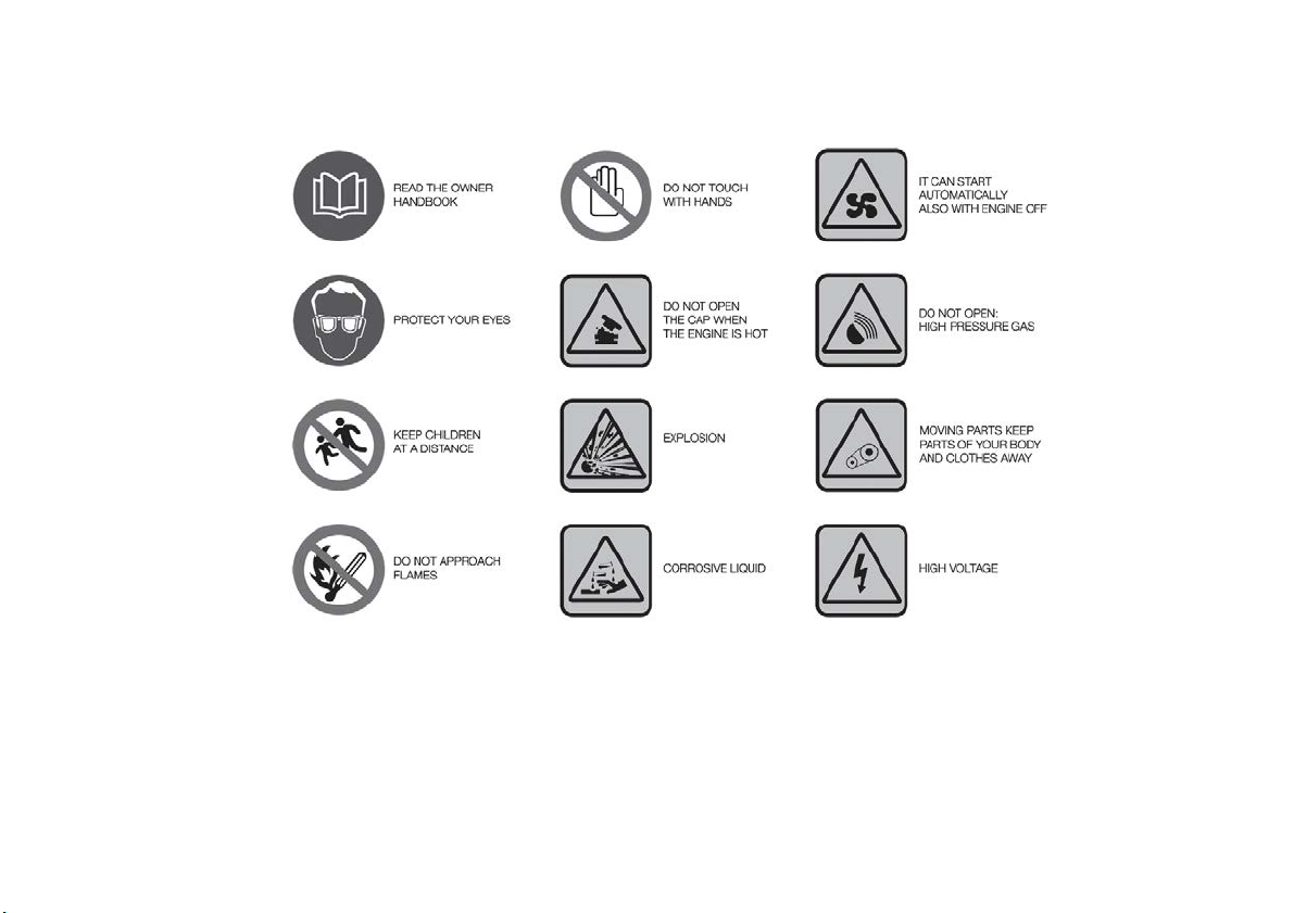
SYMBOLS
Some car components have coloured labels whose symbols indicate precautions to be observed when using this component.
A plate summarising these symbols can also be found under the bonnet.
1
J0A2300C

CHANGES/ALTERATIONS TO THE CAR
IMPORTANT Any change or alteration of the vehicle might seriously affect its safety and road holding, thus causing accidents,
in which the occupants could even be fatally injured.
IMPORTANT The use of these devices inside the passenger compartment (without an external aerial) may cause the electrical
systems to malfunction. This could compromise the safety of the car in addition to constituting a potential hazard for
passengers' health.
IMPORTANT If mobile phones/laptops/smartphones/tablets are inside the car and/or close to the electronic key, reduced
performance of the Keyless Entry/Keyless Go system may occur.

USE OF THE OWNER HANDBOOK
OPERATING INSTRUCTIONS
Each time direction instructions (left/right or forwards/backwards) about the vehicle are given, these must be understood as
regarding an occupant in the driver's seat.
Special cases not complying with this rule will be specified as appropriate in the text.
The figures in the Owner Handbook are provided by way of example only: this might imply that some details of the image do
not correspond to the actual arrangement of your vehicle.
In addition, the Handbook has been conceived considering vehicles with steering wheel on the left side; it is therefore possible
that on vehicles with steering wheel on the right side, the position or construction of some controls is not exactly mirror-like with
respect to the figure.
To identify the chapter with the information needed you can consult the index at the end of this Owner Handbook.
Chapters can be rapidly identified with dedicated graphic tabs, at the side of each odd page. A few pages further there is a key
for getting to know the chapter order and the relevant symbols in the tabs. There is in any case a textual indication of the
current chapter at the side of each even page.
WARNINGS AND PRECAUTIONS
While reading this Owner Handbook you will find a series of WARNINGS to prevent procedures that could damage your
vehicle.
There are also PRECAUTIONS that must be carefully followed to prevent incorrect use of the components of the vehicle,
which could cause accidents or injuries.
Therefore all WARNINGS and PRECAUTIONS must always be carefully followed.
WARNINGS and PRECAUTIONS are recalled in the text with the following symbols:
personal safety;
vehicle safety;
environmental protection.
NOTE These symbols, when necessary, are indicated besides the title or at the end of the line and are followed by a number.
That number recalls the corresponding warning at the end of the relevant section.
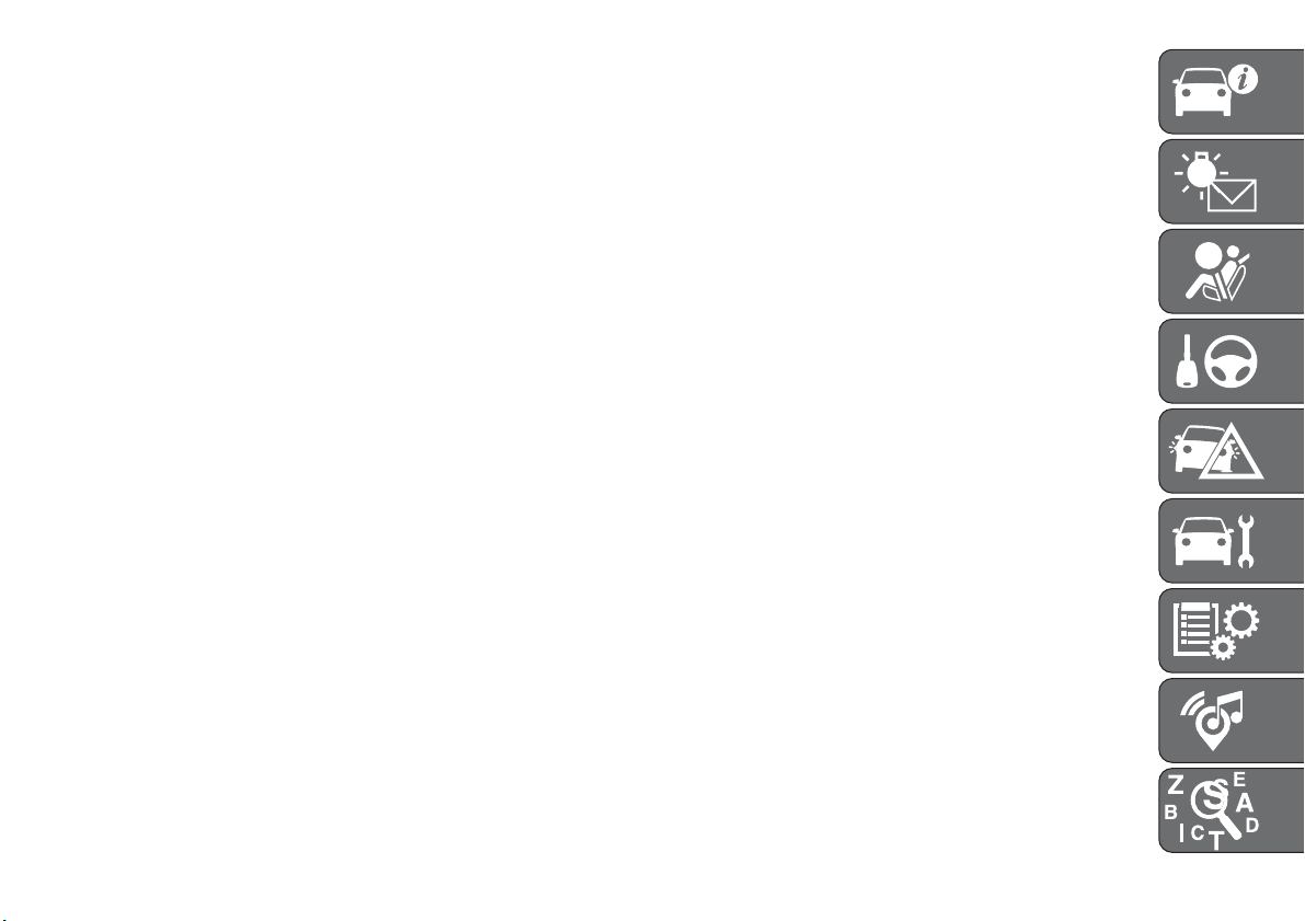
GETTING TO KNOW YOUR CAR
KNOWING THE INSTRUMENT PANEL
SAFETY
STARTING AND DRIVING
IN AN EMERGENCY
SERVICING AND MAINTENANCE
TECHNICAL SPECIFICATIONS
MULTIMEDIA
INDEX

GETTING TO KNOW YOUR CAR
In-depth knowledge of your new vehicle
starts here.
The booklet that you are reading simply
and directly explains how it is made and
how it works.
That’s why we advise you to read it
seated comfortably on board, so that
you can see immediately what is
described here for yourself.
DASHBOARD ...............10
THE KEYS .................11
IGNITION DEVICE ............12
FIAT CODE .................14
ALARM ...................14
DOORS ...................15
SEATS....................19
HEAD RESTRAINTS ...........21
STEERING WHEEL ............23
REAR VIEW MIRRORS .........23
EXTERIOR LIGHTS ............25
INTERIOR LIGHTS ............29
WINDSCREEN/REAR WINDOW
WIPER ...................29
CLIMATE CONTROL SYSTEM.....33
ELECTRIC WINDOWS ..........37
ELECTRIC SUN ROOF .........38
BONNET ..................40
BOOT ....................41
VERSION WITH LPG SYSTEM ....43
9
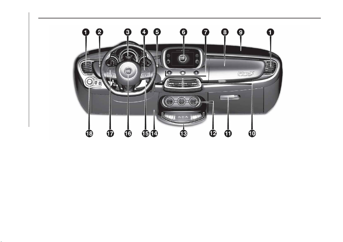
DASHBOARD
1. Adjustable side air diffusers 2. Left stalk: direction indicators, main beam headlights, flashing, Lane change
function 3. Instrument panel 4. Controls on the steering wheel: Cruise Control, Speed Limiter 5. Right stalk: windscreen
wiper/washer, rear window wiper/washer, rain sensor sensitivity level setting 6. Uconnect™ 7. Start&Stop, hazard lights,
passenger airbag LED status 8. Refrigerated upper storage compartment (for versions/markets, where
provided) 9. Passenger front airbag 10. Adjustable central air diffusers 11. Lower compartment box 12. Climate
controls 13. Buttons on central console: seat heater, steering wheel heater, USB port + AUX port (where provided) 14. Knee
bag 15. Ignition device (key or button) 16. Driver's front airbag 17. Steering wheel controls: display menu, trip computer,
multimedia, telephone, voice recognition 18. Control panel: light switch, headlight adjuster.
2
F1B0626C
10
GETTING TO KNOW YOUR CAR
THE KEYS
KEY WITH REMOTE
CONTROL
1)
1)
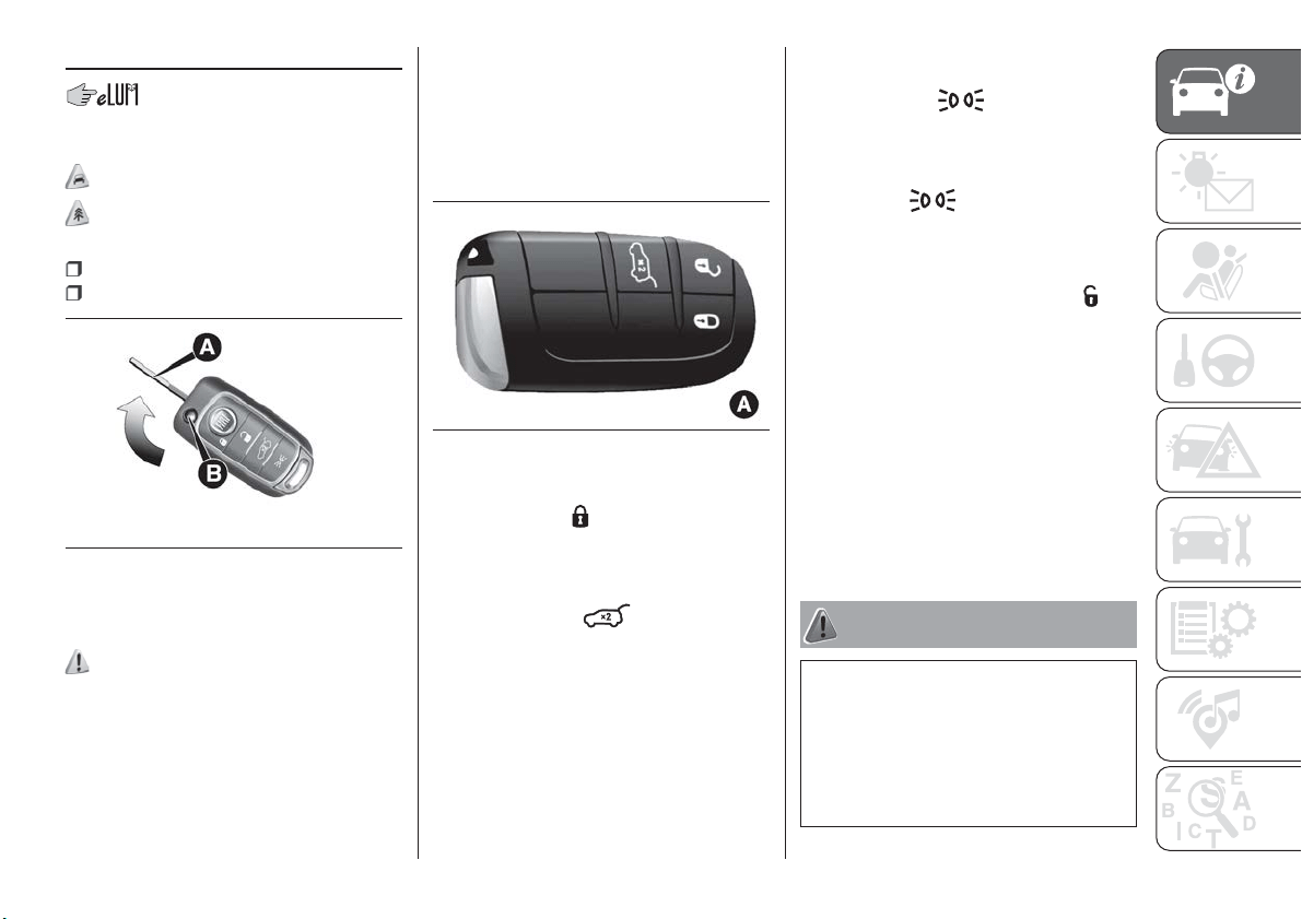
Metal insert A fig. 3 of the key operates:
the ignition device;
the driver's door lock.
Press button B to open/close the metal
insert.
1)
ELECTRONIC KEY
(versions with "Keyless Go" system)
On versions equipped with "Keyless
Go" system, the vehicle features an
electronic key A fig. 4, of which two
copies are provided.
Locking door and boot
Briefly press the
or " FIAT" button:
locking of doors and boot with roof light
off and single flash of direction
indicators (where provided).
Rapidly press the
button twice to
open the luggage compartment
remotely (where provided).
The direction indicators will flash twice
to indicate that the boot has been
opened.
Lights switching on (key with
remote control only)
Pressing button
you can remotely
control the switching on of the side and
main beam headlights, for a maximum
of 90 seconds.
Pressing the
button again the
lights switched on previously switch off
(if the parking light function was already
active it will remain so). If, when
90 seconds have passed, button
is
pressed, the main beam headlights and
the side lights will stay on for a further
30 seconds.
REQUEST FOR
ADDITIONAL KEYS
Should a new key with remote control
or a new electronic key be necessary,
go to a Fiat Dealership, taking an ID
document and the vehicle ownership
documents.
WARNING
1) Press button B only with the key away
from your body, especially your eyes and
from objects which could get damaged
(e.g. your clothes). Do not leave the key
unattended to avoid the button being
accidentally pressed while it is being
handled, e.g. by a child.
3
F1B0007C
4
F1B0008C
11
IMPORTANT
1) The electronic components inside the
key may be damaged if the key is subjected
to strong shocks. In order to ensure
complete efficiency of the electronic
devices inside the key, it should never be
exposed to direct sunlight.
IMPORTANT
1) Used batteries may be harmful to the
environment if not disposed of correctly.
They must be disposed of as specified by
law in the special containers or taken to a
Fiat Dealership, which will take care of their
disposal.
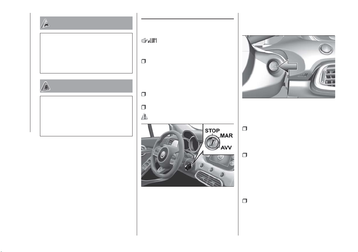
IGNITION DEVICE
Versions with key without remote
control
The key can be turned to three different
positions fig. 5:
STOP: engine off, key can be
removed, steering column locked (with
key removed). Some electrical devices
(e.g. central door locking system, alarm,
etc.) are still available;
MAR: driving position. All electrical
devices are available;
AVV: engine starting.
2) 3)
Versions with electronic key
("Keyless Go" system)
To activate the ignition device fig. 6 the
electronic key must be inside the
passenger compartment.
The ignition device activates also if the
electronic key is inside the boot or on
the rear shelf.
The ignition device has the following
possible states:
STOP: engine off, steering locked.
Some electrical devices (e.g. central
door locking system, alarm, etc.) are
still available;
MAR: driving position. All electrical
devices are available. This state can be
entered by pressing the ignition device
button once, without pressing the brake
pedal (versions with automatic
transmission) or the clutch pedal
(versions with manual gearbox);
AVV: engine starting.
NOTE The ignition device does NOT
activate if the electronic key is inside the
boot and this is open.
5
F1B0627C
6
F1B0014C
12
GETTING TO KNOW YOUR CAR
NOTE With the ignition device at MAR,
if 30 minutes pass with the vehicle
stationary (versions with manual
gearbox) or with the gear lever at P
(Park) (versions with automatic
transmission) and the engine stopped,
the ignition device will automatically
move to the STOP position.
NOTE With the engine running, it is
possible to go away from the car taking
the electronic key with you. The engine
will still be running. The vehicle will
indicate the absence of the key on
board when the door is closed.
NOTE If the device does switch off the
engine, refer to the “Display” paragraph
in the “Knowing the instrument panel”
chapter, where available, and contact
the Fiat Dealership as soon as possible.
For more information on the engine
start-up, see the description in the
"Starting the engine" paragraph, in the
"Starting and driving" chapter.
4) 5)
STEERING LOCK
Activation
Versions with key without remote
control: with the device at STOP,
remove the key and turn the steering
wheel until it locks.
IMPORTANT If the ignition key has been
moved from the MAR to the STOP
position, the steering lock cannot
engage until the key is removed from
the ignition device.
Versions with electronic key: the
steering lock engages when the driver
door is opened, with the ignition device
button at STOP and speed below
3 km/h.
Deactivation
Versions with key without remote
control: slightly moving the steering
wheel, turn the key to the MAR
position.
Versions with electronic key: the
steering lock disengages when the
ignition device is pressed and the
electronic key is recognised.
6) 7)
WARNING
2) If the ignition device has been tampered
with (e.g. an attempted theft), have it
checked by a Fiat Dealership before driving
again.
3) Always take the key with you when you
leave your vehicle to prevent someone
from accidentally operating the controls.
Remember to engage the electric parking
brake. Never leave children unattended in
the vehicle.
4) It is absolutely forbidden to carry out any
after-market operation involving steering
system or steering column modifications
(e.g. installation of anti-theft device) that
could adversely affect performance,
invalidate the warranty, cause serious
safety problems and also result in the car
not meeting type-approval requirements.
5) Never extract the mechanical key while
the vehicle is moving. The steering wheel
will automatically lock as soon as it is
turned. This holds true for cars being
towed as well.
6) Before exiting the vehicle, ALWAYS
engage the parking brake, steer the
wheels, engage the first gear if uphill and
the reverse if downhill. On versions with
automatic transmission, bring the gear
lever to P (Park) and press the ignition
device to bring it to STOP. If the vehicle is
parked on a steep slope, chock the wheels
with wedges or stones. When leaving the
car, always lock all the doors by pressing
the dedicated button on the handle (see
"Keyless Entry" in the paragraph "Doors").
7) For versions equipped with the Full
Keyless System, do not leave the
electronic key inside or near the car or in a
place accessible to children. Do not leave
the vehicle with the ignition device in MAR
position. A child could activate the electric
window winders, other controls or even
start the vehicle.
13
FIAT CODE
The Fiat Code system prevents
unauthorised use of the vehicle,
disabling engine starting.
The system does not need to be
enabled/activated: operation is
automatic, regardless of the fact that
the vehicle's doors are locked or
unlocked.
When the ignition device is set to MAR,
the Fiat Code system identifies the
code transmitted by the key. If the code
is recognised as valid, the Fiat Code
system enables engine starting.
When the ignition device is brought
back to STOP, the Fiat Code system
deactivates the control unit controlling
the engine, thus preventing its starting.
For the correct engine starting
procedures, see the instructions in the
"Starting the engine" paragraph,
"Starting and driving" chapter.
IRREGULAR OPERATION
If, during starting, the key code is not
correctly recognised, the
icon is
displayed on the instrument panel (see
the instructions in the "Warning lights
and messages" paragraph, "Knowing
the instrument panel" chapter). This
condition leads to the engine switching
off after 2 seconds. In this case, bring
the ignition device to STOP and then to
MAR; if it is still blocked, try with the
other keys provided. If it is still not
possible to start the engine, contact a
Fiat Dealership.
If the
icon is displayed while
driving, this means that the system is
running a self-diagnosis (e.g. due to a
voltage drop). If the display persists,
contact a Fiat Dealership.
ALARM
Activation of the alarm triggers the
acoustic warning and the direction
indicators.
IMPORTANT The alarm is adapted by
the Manufacturer to meet the
requirements of the various countries
where the vehicle is marketed.
TURNING THE ALARM ON
(where provided)
With the doors, bonnet and tailgate
closed and the ignition device on to
STOP, point the key with remote control
or electronic key towards the vehicle
and press and release the
" FIAT"
button.
For versions with electronic key, the
alarm can also be armed by pressing
the "door lock" button, located on the
door external handle. For more
information, refer to the Keyless Entry
paragraph a few pages further on.
The system emits a visual and acoustic
warning (where provided) and enables
door locking.
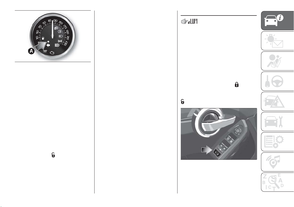
With the alarm on, warning light A
fig. 7 flashes on the instrument panel.
14
GETTING TO KNOW YOUR CAR
The activation of the alarm is preceded
by a self-diagnosis stage: if a fault is
detected, the system emits a further
acoustic warning.
Locking the doors without engaging the
alarm is also always possible by locking
the doors by putting the metal insert of
the key inside the driver side door lock.
IMPORTANT If the doors are unlocked
by putting the metal insert into the
driver side door lock, the alarm, if
previously enabled, is not disabled. It
will be possible to disable the alarm by
turning the ignition device to MAR, or
by pressing button
on the remote
control.
TURNING THE ALARM
OFF
IMPORTANT The alarm does not switch
off when the central opening is
activated using the metal insert in the
key.
DISABLING THE ALARM
To completely deactivate the alarm (e.g.
during a long period of vehicle
inactivity), close the doors by turning
the metal insert of the key with remote
control in the door lock.
IMPORTANT If the batteries of the key
with the remote control run out or there
is a fault with the system, the alarm can
be switched off by setting the ignition
device to MAR.
DOORS
LOCKING/UNLOCKING
DOORS FROM THE
INSIDE
Central locking/unlocking
If all doors are closed properly, they will
automatically be locked once the
vehicle has exceeded 20 km/h
("Autoclose" function). This function can
also be disabled using the menu on the
instrument panel.
To lock the doors, press the
button
located on the front door trim fig. 8.
To unlock the doors, press the
button.
Manual locking/unlocking
Doors can also be locked/unlocked by
rotating the device A fig. 9, integrated
into the front door inner handles.
7
F1B0015C
8
F1B0024C
15
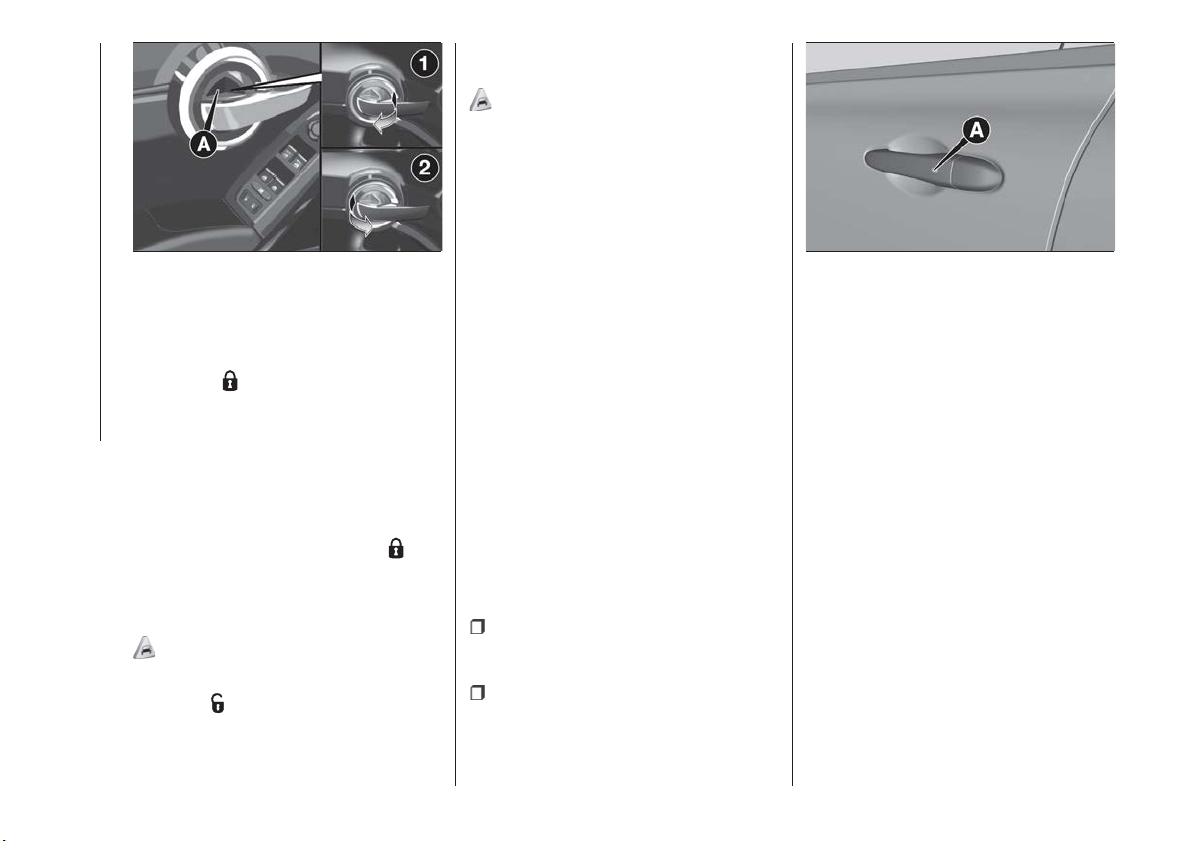
Operating the rear door device locks
only the door concerned.
Position 1: door unlocked
Position 2
: door locked
Operating the handle of the front doors
unlocks all doors and the tailgate.
LOCKING/UNLOCKING
DOORS FROM THE
OUTSIDE
Locking doors from the outside
With the doors closed, press the
"
FIAT" button on the key or fit and then
turn its metal insert in the driver's door
lock.
2)
Door unlocking from the outside
Press the
button on the key or turn
its metal insert in the driver's door lock.
PASSIVE ENTRY
(where provided)
3)
The Keyless Entry system can identify
the electronic key near the doors and
tailgate.
The system enables the doors (or the
tailgate) to be locked/released without
pressing any button on the electronic
key.
If the system recognises that the
electronic key detected outside the
vehicle is valid, the owner of the key
can simply grasp one of the front
handles to deactivate the alarm and
unlock the door and tailgate opening
mechanism.
Where the function is provided,
grasping the handle of the driver's door
unlocks the driver's side door or all
doors depending on the mode set
using the display menu or the
Uconnect™ system.
Door locking
To lock the doors, proceed as follows:
make sure that you have the
electronic key with you and are near the
driver or passenger door handle;
press the "door locking" button A
fig. 10 on the handle: this will lock all
doors and the tailgate. Locking the
doors will also activate the alarm (where
provided).
IMPORTANT After pressing the "door
locking" button, you need to wait two
seconds before the doors can be
unlocked again using the door handle.
It is therefore possible to check whether
the vehicle is locked correctly by pulling
the door handle within 2 seconds. The
doors will not be unlocked again.
IMPORTANT Do not simultaneously
lock and unlock by pulling the handle
(see fig. 11 ).
9
F1B0017C
10
F1B0063C
16
GETTING TO KNOW YOUR CAR
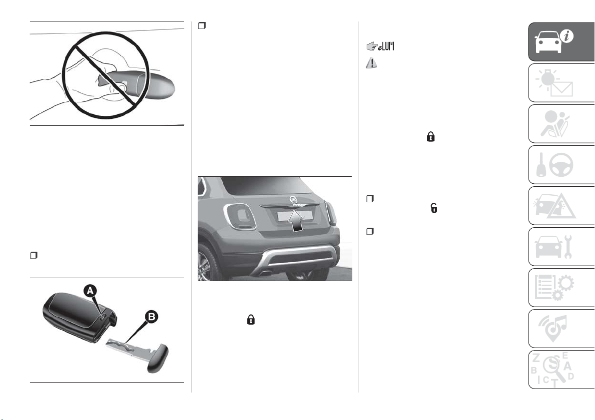
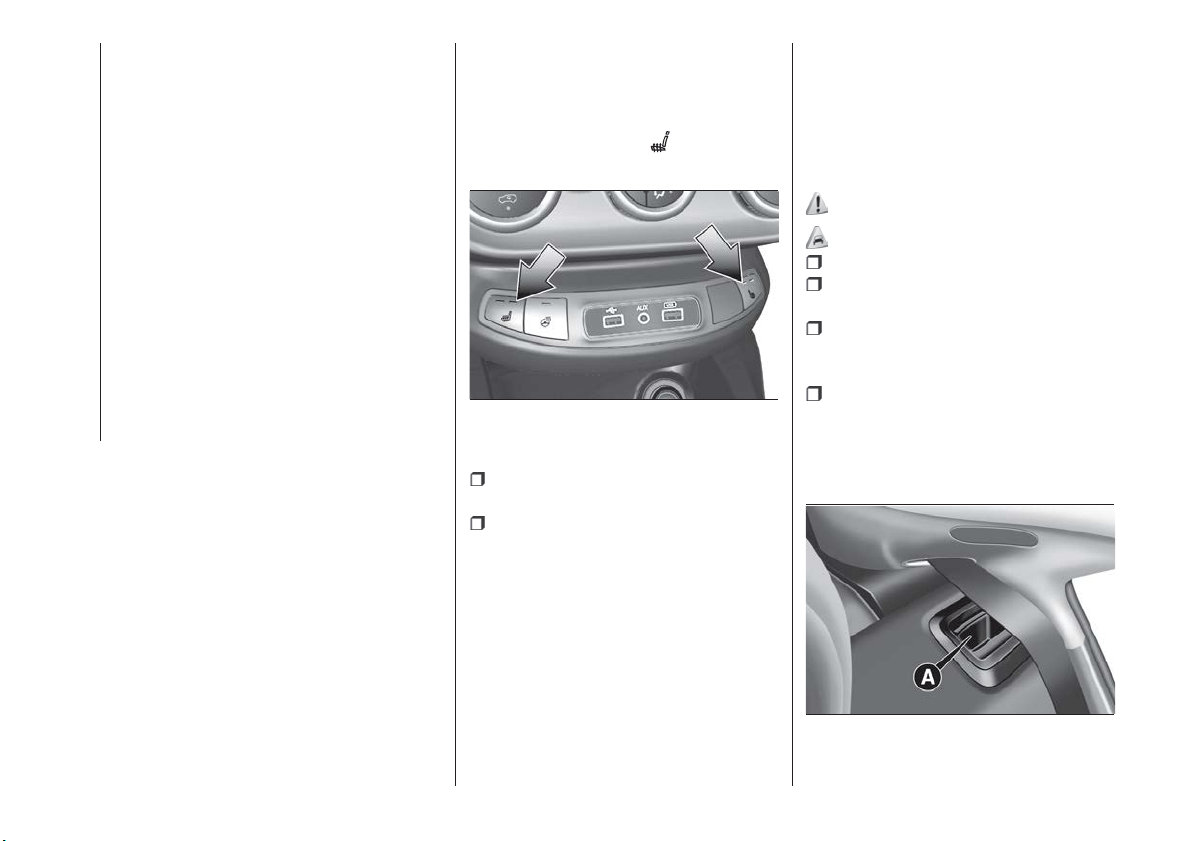
Driver side door emergency
opening
If the electronic key does not work (e.g.
because its battery is flat), the
emergency metal insert inside the key
can anyway be used to operate the
lock, unlocking the driver side door.
To extract the metal insert, proceed as
follows:
press point A fig. 12 and pull out the
metal insert B;
insert the metal insert in the driver
side door lock and turn it to unlock the
door.
Tailgate locking
Approaching the tailgate with a valid
electronic key, press the opening button
fig. 13 underneath the tailgate handle to
lock/unlock the luggage compartment.
NOTE If there is an alarm system, the
latter will be temporarily disabled only
for the boot area. After closing the boot,
the alarm system will be reactivated
again.
The tailgate can however be locked by
pressing the
button on the electronic
key or on the inside door panel.
NOTE The tailgate door lock also
performs a central locking of the doors.
Boot opening is disabled while the car
is moving.
DEAD LOCK
(where provided)
8)
This safety device inhibits the operation
of the interior door handles and the
door locking/unlocking button.
Activating the device
The device is enabled on all the doors
by pressing the
" FIAT" button on
the key with remote control twice
quickly.
Deactivating the device
The device disengages automatically:
when the doors are unlocked
(pressing button
on the key with
remote control);
when the ignition device is set to
MAR.
11
F1B0251C
12
F1B0020C
13
F1B0166C
17
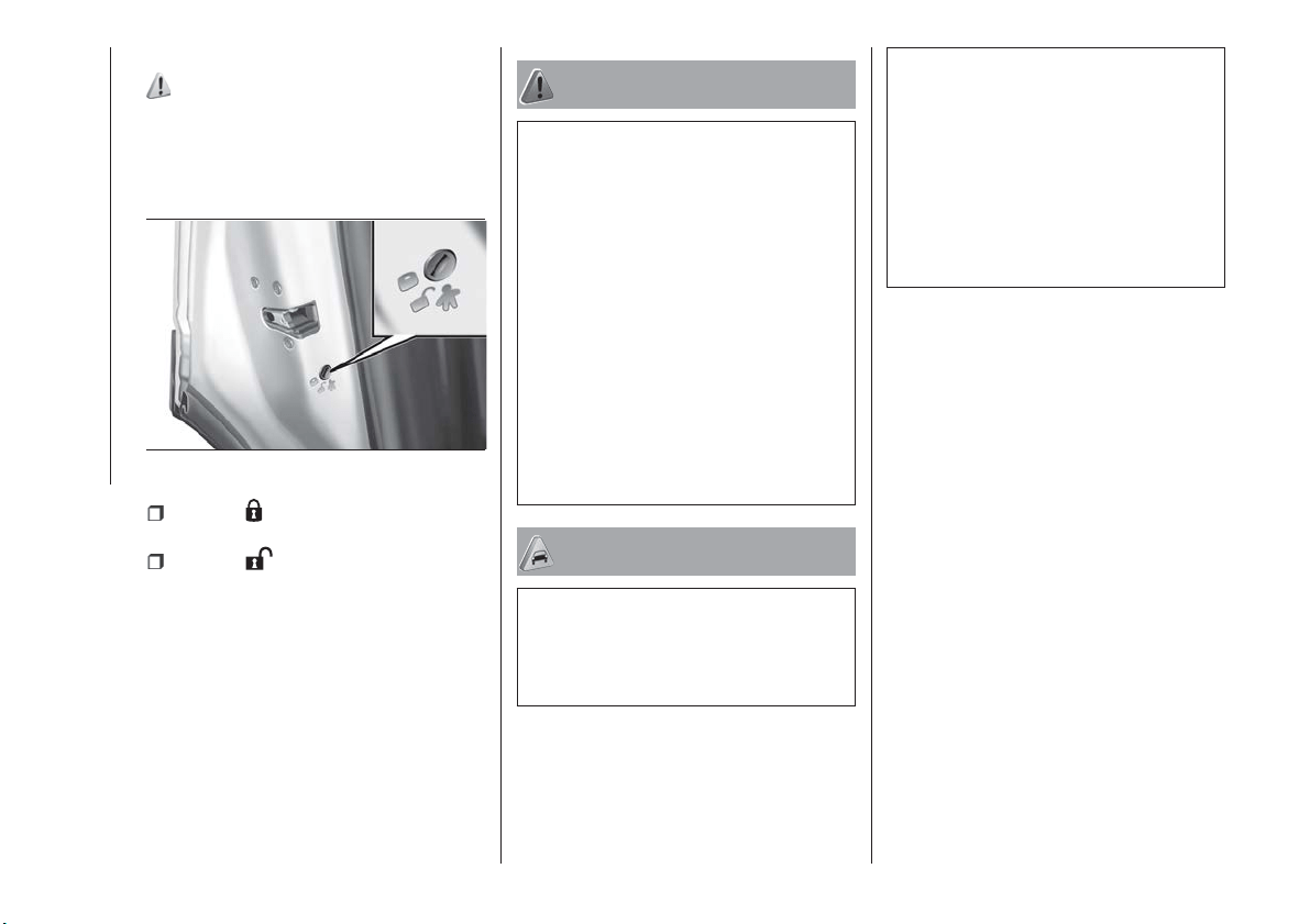
CHILD SAFETY DEVICE
9) 10)
This system prevents the rear doors
from being opened from the inside.
The fig. 14 device can only be engaged
with the doors open:
position : device engaged (door
locked);
position : device not engaged
(door may be opened from the inside).
The device remains engaged even if the
doors are electrically unlocked.
IMPORTANT The rear doors cannot be
opened from the inside when the child
safety device is engaged.
WARNING
8) Once the Dead Lock system is engaged,
it is impossible to open the doors from
inside the vehicle. Before getting out of the
car, please therefore check that there is
no-one left inside.
9) NEVER leave children unattended inside
the car, let alone leave the car with the
doors unlocked in a place that children can
access easily. Children may seriously, or
even fatally, injure themselves. Also ensure
that children do not inadvertently operate
the electric parking brake, the brake pedal
or the automatic transmission lever.
10) Always use this device when carrying
children. After engaging the child lock on
both rear doors, check for effective
engagement by trying to open a door with
the internal handle.
IMPORTANT
2) Make sure to take the key with you once
a door or the tailgate is locked, to prevent
locking the same key inside the vehicle. If
the key has been locked in, it can only be
recovered using the second provided key.
3) The operation of the recognition system
depends on various factors, such as, for
example, any electromagnetic wave
interference from external sources (e.g.
mobile phones), the charge of the battery in
the electronic key and the presence of
metal objects near the key or the car. In
these cases it is still possible to unlock the
doors by using the metal insert in the
electronic key (see description on the
following pages).
14
F1B0023C
18
GETTING TO KNOW YOUR CAR
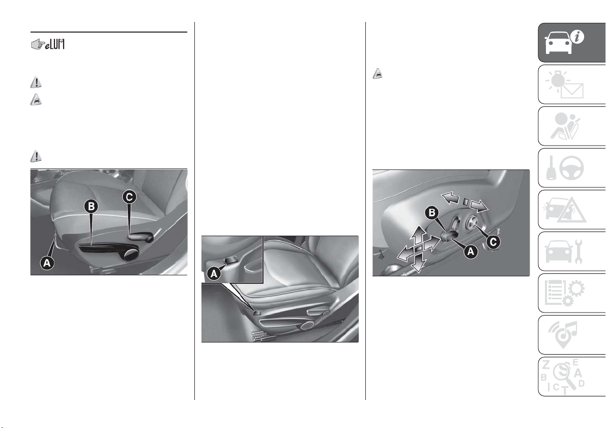
SEATS
FRONT SEATS WITH
MANUAL ADJUSTMENT
11)
4)
Longitudinal adjustment
Lift lever A fig. 15 and push the seat
forwards or backwards.
12)
IMPORTANT Carry out the adjustment
while sitting on the seat involved (driver
side or passenger side).
Height adjustment
Move lever B upwards or downwards to
achieve the required height.
IMPORTANT Carry out the adjustment
while sitting on the seat involved (driver
side or passenger side).
Backrest angle adjustment
Move lever C to adjust the backrest
angle, accompanying it with the
movement of the torso (operate the
lever until the desired position is
reached, then release it).
Electric lumbar adjustment
When the ignition device is at MAR,
press button A fig. 16 to adjust the
lumbar area support, until the maximum
driving comfort is achieved.
ELECTRICALLY
ADJUSTABLE FRONT
SEATS
(where provided)
5)
The buttons for electrical seat
adjustment are on the outer side of the
seat, near the floor.
These buttons can be used to adjust
the height, the lengthwise position in
relation to the vehicle and the angle of
the backrest.
Height adjustment
Use the front or rear part of the switch
A fig. 17 to modify the height and/or the
angle of the seat cushion.
Longitudinal adjustment
Push switch A forwards or backwards
to move the seat in the corresponding
direction.
15
F1B0019C
16
F1B0016C
17
F1B0018C
19
Backrest angle adjustment
Push switch B forwards or backwards
to adjust the backrest in the
corresponding direction.
Electric lumbar adjustment
Use the joystick C to actuate the
lumbar area device until the maximum
driving comfort is achieved.
IMPORTANT The electrical adjustment
is only allowed when the ignition device
is turned to MAR and for about
3 minutes after it is turned to STOP.
With the car STOPPED, after the door
has been opened, the system will allow
an additional 3-minute adjustment
period.
FRONT SEAT ELECTRIC
HEATING
(where provided)
With ignition device in the MAR
position, press buttons
fig. 18 on the
dashboard.
You can select two heating levels:
“minimum heating”: one orange LED
lit on the buttons;
"maximum heating": two orange
LEDs lit on the buttons.
After selecting one heating level, you
need to wait for a few minutes until
warm air flows into the compartment.
When the "maximum heating" setting is
selected, the heater produces a
boosted heat level for the first minutes
of operation.
IMPORTANT To preserve the battery
charge, this function cannot be
activated when the engine is off.
REAR SEATS
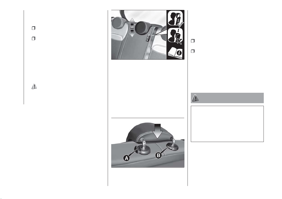
Partial extension of the boot (1/3 or
2/3)
13)
6)
remove the rear shelf;
completely lower the rear seat head
restraints;
move the seat belt to the side,
making sure that it is fully extended and
not twisted;
operate release device A fig. 19 to
fold the required backrest section. After
release a red mark is visible.
Accompany the backrest during folding.
18
F1B0624C
19
F1B0027C
20
GETTING TO KNOW YOUR CAR
Repositioning the backrests
Move the seat belts to the side, making
sure that they are correctly extended
and not twisted.
Raise the backrests and push them
back until the locking click of both
retainers is heard. Visually check that
the red marks have disappeared from
the release devices A fig. 19. The red
marks indicate that the backrest is not
secured.
WARNING
11) All adjustments must be made with the
car stationary.
12) Once you have released the
adjustment lever, always check that the
seat is locked on the guides by trying to
move it back and forth. If the seat is not
locked into place, it may unexpectedly slide
and cause the driver to lose control of the
car.
13) Make sure the backrests are properly
secured at both sides (not visible "red
notches) to prevent them from moving
forward, in the event of sharp braking, with
possible impact with of the passengers.
IMPORTANT
4) The fabric upholstery of the seats has
been designed to withstand long-term wear
deriving from normal use of the car. Some
precautions are however required. Avoid
prolonged and/or excessive rubbing
against clothing accessories such as metal
buckles and Velcro strips which, by
applying a high pressure on the fabric in a
small area, could cause it to break, thereby
damaging the upholstery.
5) Do not arrange objects beneath the
electrically adjustable seat and do not
impede its movement, since the controls
may be damaged. The fabric upholstery of
the seats has been designed to withstand
long-term wear deriving from normal use of
the car. Some precautions are however
required. Avoid prolonged and/or excessive
rubbing against clothing accessories such
as metal buckles and Velcro strips which,
by applying a high pressure on the fabric in
a small area, could cause it to break,
thereby damaging the upholstery. They
may also restrict the seat travel.
6) Before tilting the backrest, remove any
objects on the seat cushion.
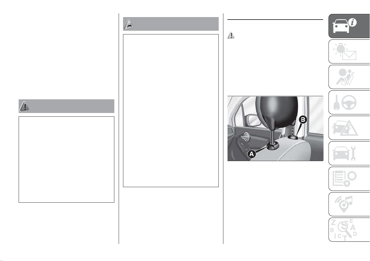
HEAD RESTRAINTS
FRONT
14)
Adjustment
They can be adjusted to 4 height
positions (completely raised /
2 intermediate positions / completely
lowered).
Upward adjustment: raise the head
restraint until it clicks into place.
Downward adjustment: press button A
fig. 20 and lower the head restraint.
20
F1B0029C
21
Removal
Proceed as follows to remove the head
restraint:
tilt the backrest (to prevent it from
coming into contact with the roof);
press both buttons A and B fig. 20 at
the side of the two supports, then
remove the head restraint.
IMPORTANT Always reposition the
head restraints if they have been
removed before starting to drive
normally.
REAR
14)
Adjustment
Three head restraints that can be
height-adjusted to 3 positions
(completely raised / intermediate /
completely lowered) are provided for
the rear seats
Upward adjustment: raise the head
restraint until it clicks into place.
On some versions, the label
fig. 21 reminds the user of the centre
rear seat to adjust the headrest in a
correct position, pulling it upward in
both preset positions.
IMPORTANT The headrests must be
placed in rest position (fully lowered) to
guarantee visibility to the driver.
Downward adjustment: press button A
fig. 22 and lower the head restraint.
Removal
Proceed as follows to remove the head
restraint:
raise the head restraint to its
maximum height;
press buttons A and B fig. 22 at the
side of the two supports, then remove
the head restraint.
IMPORTANT Always reposition the
head restraints if they have been
removed before starting to drive
normally.
WARNING
14) Head restraints must be adjusted so
that the head, rather than the neck, rests
on them. Only in this case they can protect
your head correctly. Any removed head
restraints must be repositioned correctly, in
order to protect the occupants in the event
of impact: follow the instructions above.
21
F1B0236C
22
F1B0030C
22
GETTING TO KNOW YOUR CAR
STEERING WHEEL
15) 16)
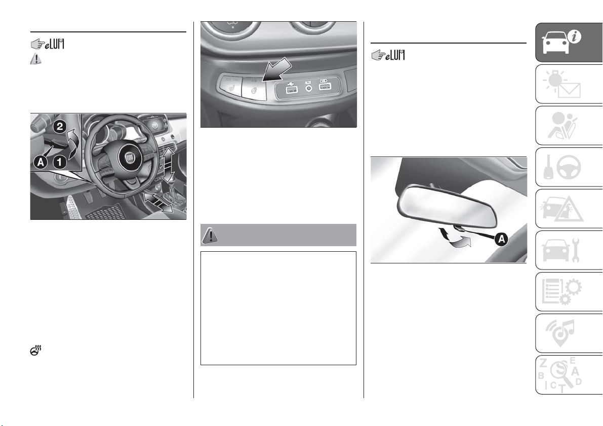
ADJUSTMENTS
The steering wheel can be adjusted
both in height and axially.
To adjust, move lever A
fig. 23 downwards to position 1, then
adjust the steering wheel to the most
suitable position and lock it in position
by moving lever A to position 2.
ELECTRIC STEERING
WHEEL HEATING
(where provided)
With ignition device at MAR, press the
fig. 24 button on the dashboard.
When the function is on, the LED on the
button switches on.
IMPORTANT The activation of this
function with the engine stopped could
flatten the battery.
WARNING
15) All adjustments must be carried out
only with the car stationary and engine
stopped.
16) It is absolutely forbidden to carry out
any after-market operation involving
steering system or steering column
modifications (e.g. installation of anti-theft
device) that could adversely affect
performance and safety, invalidate the
warranty and also result in the car not
meeting type-approval requirements.
REAR VIEW
MIRRORS
INTERIOR MIRROR
Manual adjustment: operate lever A
fig. 25 to adjust the mirror into two
different positions: normal or anti-glare.
The mirror is fitted with a safety device
that causes its release in the event of a
violent impact with a passenger.
Electrochromic mirror
On some versions, an electrochromic
mirror is available, that can
automatically modify its reflecting action
to prevent dazzling the driver fig. 26.
The electrochromic mirror has an
ON/OFF button to activate/deactivate
the electrochromic anti-glare function.
23
F1B0628C
24
F1B0625C
25
F1B0033C
23
When reverse gear is engaged, the
mirror is automatically set for daytime
use.
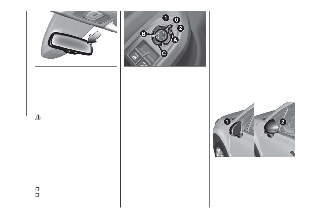
DOOR MIRRORS
Electric adjustment
17)
Adjusting the mirrors is possible with
the ignition device at MAR and for
about 3 minutes after the ignition device
switches to STOP (or also after the
mechanical key has been extracted, for
cars equipped with mechanical key with
remote control). When one of the front
doors is opened this operation is
disabled.
Select the desired mirror using device A
fig. 27:
position 1: left mirror selected;
position 2: right mirror selected;
To adjust the selected mirror, press
button B in the four directions shown by
the arrows.
IMPORTANT Once adjustment is
complete, rotate device A to position
0 to prevent accidental movements.
Electric folding
(where provided)
To fold back the mirrors press button C.
Press the button again to restore the
mirrors to the driving position. Once the
chosen command has been given,
before the mirror reaches the fully open
or closed position its direction of travel
can be reversed by pressing button C
again.
It is possible to fold or open the mirrors
with the ignition device at MAR and for
about 3 minutes after the ignition device
switches to STOP (or also after the
mechanical key has been extracted, for
cars equipped with mechanical key with
remote control). When one of the front
doors is opened this operation is
disabled.
IMPORTANT NOTE Except when using
this function for passing through narrow
gaps, when on the move the mirrors
must always be kept open (position 1
fig. 28 ) and must never be folded
(position 2).
26
F1B0034C
27
F1B0035C
28
F1B0340C
24
GETTING TO KNOW YOUR CAR
Mirrors realignment operation
In case one of the door mirrors has
been moved manually it may occur that
the mirror itself does not retain its
position in a stable way while driving.
In that case it is necessary to carry out
the following realignment operation:
manually close the mirror in parking
position, folding it from position 1 to
position 2 (see fig. 28 );
Actuate the mirrors opening control
one or two times C fig. 27 to realign the
system and bring both mirrors in the
driving position.
WARNING
17) As the driver's door mirror is curved, it
may slightly alter the perception of
distance.
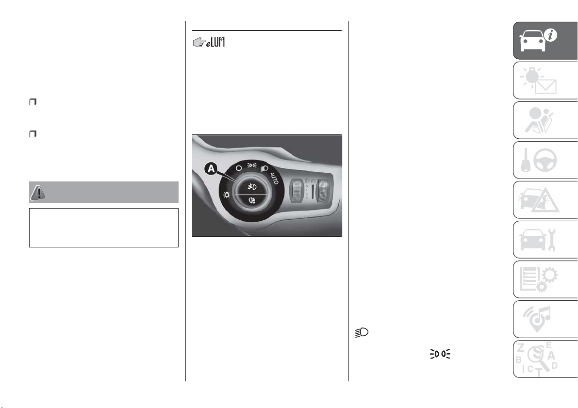
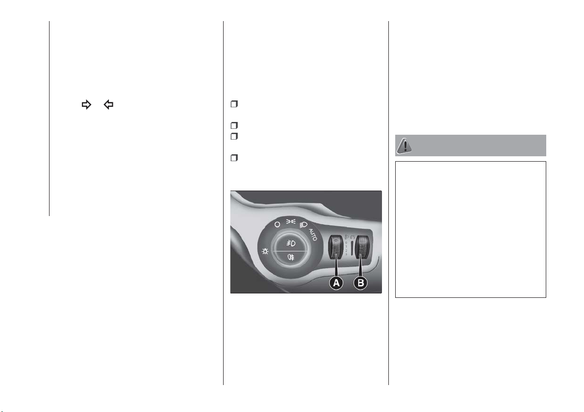
EXTERIOR LIGHTS
LIGHT SWITCH
Light switch ring A fig. 29, located on
the left side of the dashboard, controls
operation of side lights, daytime running
lights, dipped beam headlights, fog
lights and adjusts the instrument panel
and control button graphic dimmer.
With the ignition device in the MAR
position, the instrument panel and the
various dashboard controls will come
on with the external lights.
AUTO FUNCTION
(Dusk sensor)
(where provided)
This is an infrared LED sensor that
works in conjunction with the rain
sensor and is located on the
windscreen. It is able to detect
variations in outside lighting based on
the light sensitivity set in the display
Menu or the Uconnect™ system.
The higher the sensitivity, the lower the
amount of external light needed to
automatically switch the external lights
on.
Function activation
Turn the light switch ring nut to AUTO.
IMPORTANT The function can only be
activated with the ignition device at
MAR.
Function deactivation
To deactivate the function, turn the light
switch ring nut to a position other than
AUTO.
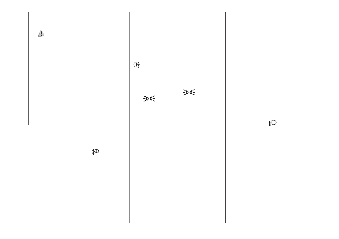
DIPPED BEAM
HEADLIGHTS
With the ignition device in MAR
position, turn the light switch ring to
: the position lights, the dipped
beam headlights and the instrument
panel come on; the
light on the
panel illuminates.
29
F1B0206C
25
DAYTIME RUNNING
LIGHTS (DRL)
"Daytime Running Lights"
18) 19)
With the ignition device in the MAR
position and the light ring turned to the
O position, the daytime running lights
are automatically activated. The other
lights and interior lighting remain off.
The daytime running lights are
temporarily deactivated when the
direction indicators are activated. When
the direction indicators are deactivated,
the daylight running lights are
reactivated.
FOG LIGHTS
(where provided)
The fog light switch is integrated with
the light switch.
With the ignition device in the MAR
position and the dipped beam
headlights on, press the
button to
switch on the fog lights.
When the fog lights are on, the position
and number plates lights are on while
the daytime running lights are off.
To switch them off, press the button
again or turn the light switch ring to O.
REAR FOG LIGHT
(where provided)
The button which turns the rear fog light
on and off is integrated in the light
switch.
With the ignition device in the MAR
position and the dipped beam
headlights or fog lights on, press the
button to switch on the rear fog
light.
PARKING LIGHTS
These can be turned on by turning the
light switch ring to the
position.
The
warning light switches on in
the instrument panel.
IMPORTANT NOTE Do not select this
light switch position when the car is
moving, but only to indicate that the car
is parked when prescribed by the
regulations in force in the country where
you are driving (Highway Code).
To turn the lights off, turn the light
switch ring to the O position
HEADLIGHTS OFF DELAY
(Follow me home)
Activation
With multifunction display and
Uconnect™Radio: turn the ignition
device to STOP. Within 2 minutes, pull
the left stalk to headlight flashing mode:
the headlight off delay is activated for
30 seconds. The function can be
activated for 7 times in sequence, i.e.
up to a total of 210 seconds.
With reconfigurable multifunction
display and/orUconnect™7'': the
headlight off delay can be set (from 0,
30, 60 to 90 seconds) in the Menu.
If the headlight off delay is set to
0 seconds, it is possible to turn on the
lights for a predefined time of
30 seconds using the main beam
headlights stalk within 2 minutes after
stopping the engine. It is possible to
turn on the lights 7 times, for a
maximum of 210 seconds.
If the value set on the Menu is different
from 0, the lights can be switched of for
the predetermined time by taking the
ring from position
(with the engine
running) to position O (with the engine
off).
The function can be activated
automatically on versions with dusk
sensor: turn the ring to the AUTO
position with the engine running. The
dipped beam headlights will be turned
on if the sensor detects a low level of
light. The headlights off delay is
activated automatically when the engine
is switched off with the headlights on
for the time selected in the Menu.
26
GETTING TO KNOW YOUR CAR
Deactivation
If the function is activated by using the
left steering wheel stalk, the function
can be deactivated by holding the left
lever in "main beam flashing" mode for
longer than 2 seconds or by waiting for
the deactivation time shown on the
display.
The function cannot be deactivated if it
is activated using the light line. The
headlights will be switched off at the
end of the set time.
Turning the ignition device to the MAR
position will deactivate the function.
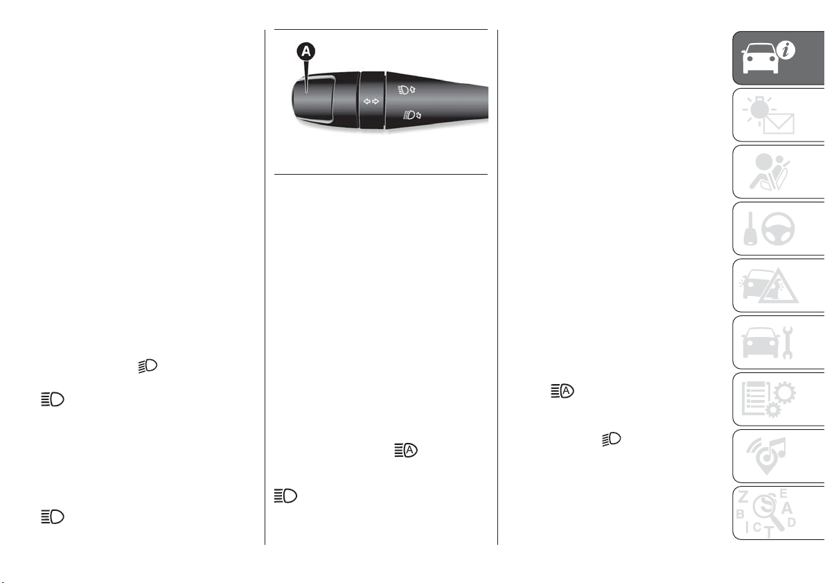
MAIN BEAM HEADLIGHTS
To activate the fixed main beam
headlights, with the ignition device in
MAR, push left lever A fig. 30 towards
the dashboard. The light switch should
be turned to AUTO with the dipped
beam headlights on, or it should be
turned to position
.
With main beam headlights on, the
warning light on the instrument
panel will come on at the same time.
Flashing the headlights
Pull the lever A fig. 30 towards you;
when released it returns automatically
to the stable, central position.
With main beam headlights on, the
warning light on the instrument
panel will come on at the same time.
Automatic main beam headlights
(where provided)
In order not to disturb other road users,
the main beam headlights are
automatically turned off when
approaching oncoming vehicles or
when following a vehicle travelling in the
same direction.
This function can be set using the
display Menu (see the instructions in the
"Display" paragraph, "Knowing the
instrument panel" chapter); to activate
it, turn the light switch ring to AUTO.
To activate the function, push the lever
towards the instrument panel (it will
hold this position): the
light
illuminates on the instrument panel. If
the main beam headlights are on, the
light also illuminates. If the car is
stopped with the setting just described,
when it is restarted the automatic main
beam headlight function will have to be
set again: return the lever to the central
position and push it towards the
instrument panel as before.
When the speed is over 40 km/h and
the function is active, returning the lever
to the stable central position
deactivates the function and switches
the main beam headlights off.
When the speed is lower than 15 km/h
and the function is active, the system
automatically switches main beam
headlights off.
If the lever is pulled back to the central
stable position and then pushed
towards the instrument panel again and
left there, this is interpreted as a request
for permanent main beam headlights:
the light illuminates on the instrument
panel and the main beam headlights
remain on until the car's speed rises
back above 40 km/h. Above this speed,
the function is automatically reactivated
and the
light illuminates again on
the instrument panel.
To disable the function, turn the light
switch ring to the
position.
30
F1B0037C
27
DIRECTION INDICATORS
Bring left stalk A fig. 30 to the (stable)
position:
upwards: activates the right direction
indicator;
downwards: activates the left direction
indicator.
The
or warning light respectively
will flash on the instrument panel.
The direction indicators switch off
automatically when the steering wheel
is straightened or when the daytime
running lights (DRL)/parking lights are
activated.
"Lane Change" function
If you wish to signal a lane change while
running, place the left stalk in the
unstable position for less than half a
second.
The direction indicator on the side
selected will flash five times and then
switch off automatically.
HEADLIGHT ALIGNMENT
ADJUSTMENT
Headlight alignment corrector
The headlight alignment corrector
operates with ignition device at MAR
and dipped headlights on.
To adjust rotate ring nut A fig. 31.
Position 0: 1 or 2 occupants on
front seats;
Position 1: 4 or 5 occupants
Position 2: 4 or 5 occupants+ load
in the boot
Position 3: driver + maximum
admissible load stowed only in the
luggage compartment.
IMPORTANT Check the headlight
alignment each time the weight of the
load transported changes.
INSTRUMENT PANEL AND
CONTROL BUTTON
GRAPHIC BRIGHTNESS
ADJUSTMENT
With side lights or headlights on, turn
ring nut B fig. 31 upwards to increase
light brightness of the instrument panel
and of the control button graphics, or
turn the ring nut downwards to
decrease it.
WARNING
18) The daytime running lights are an
alternative to the dipped headlights for
driving during the daytime in countries
where it is compulsory to have lights on
during the day; where it is not compulsory,
the use of daytime running lights is
permitted.
19) Daytime running lights cannot replace
dipped beam headlights when driving at
night or through tunnels. The use of
daytime running lights is governed by the
highway code of the country in which you
are driving. Comply with legal
requirements.
31
F1B0207C
28
GETTING TO KNOW YOUR CAR
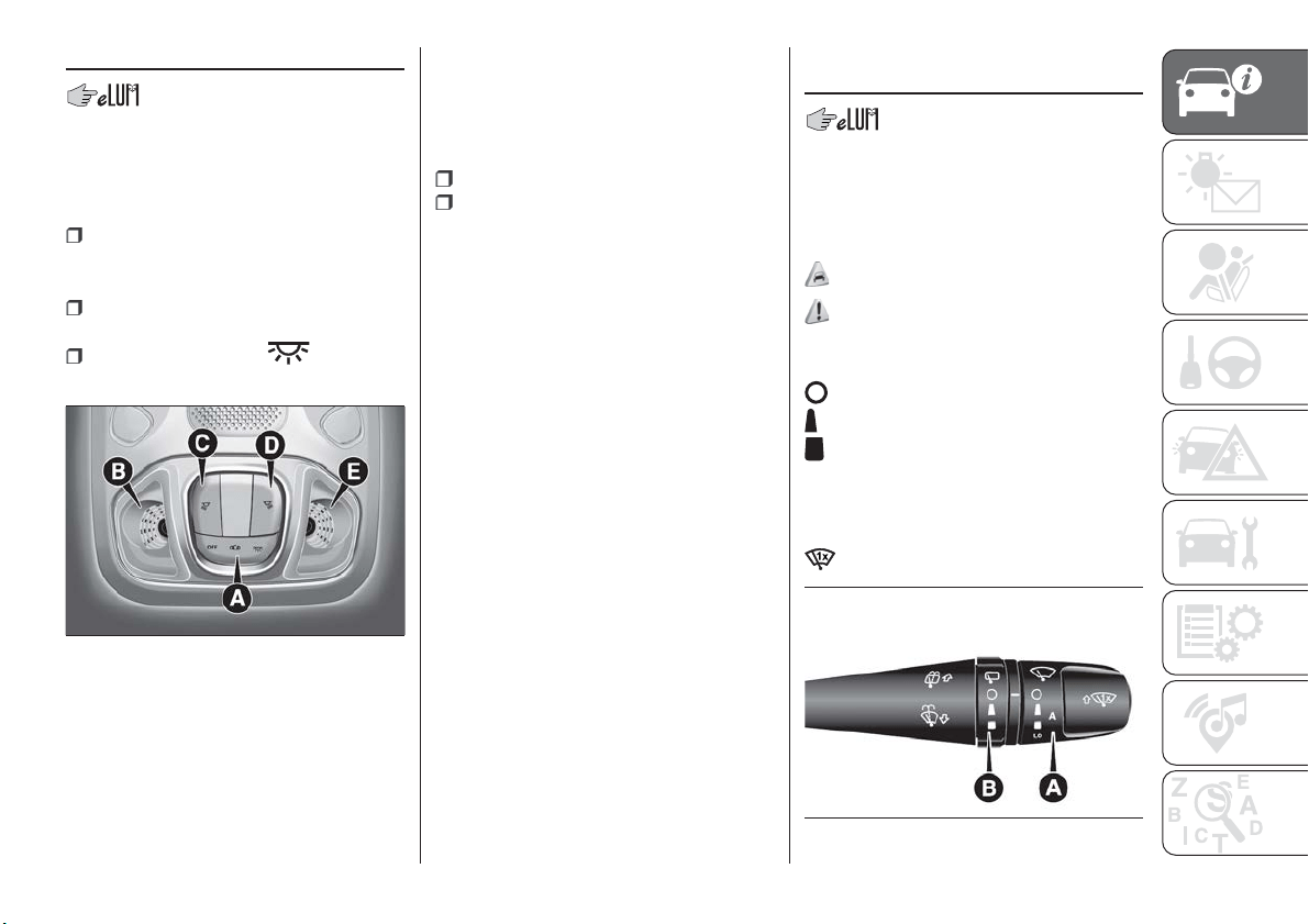
INTERIOR LIGHTS
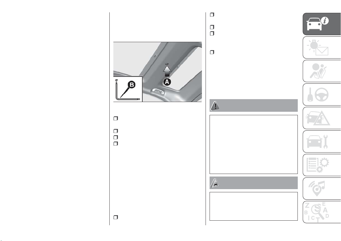
FRONT ROOF LIGHT
Switch A fig. 32 is used to switch on/off
the roof light bulbs.
Switch A positions:
central position: lights B and E
switch on/off when the doors are
opened/closed;
pressed to the left (OFF): lights B and
E are always switched off;
pressed to the right ( ): lights B
and E are always switched on.
The lights switch on/off gradually.
Switch C switches light B on/off.
Switch D switches light E on/off.
Roof light timing
On certain versions, to facilitate getting
in/out of the vehicle at night or in
poorly-lit areas, two timed modes have
been provided.
Timing while getting into the vehicle
Timing while getting out of the
vehicle.
WINDSCREEN/REAR
WINDOW WIPER
Operation is only possible with the
ignition device at MAR.
SCREEN WIPER/WASHER
Operation
7) 8)
20)
Ring nut A fig. 33 can be set to the
following positions:
windscreen wiper off.
fixed intermittent wipe (slow)
intermittent operation linked to the
speed
LO constant slow wipe
HI constant fast wipe
MIST function
32
F1B0041C
33
F1B0635C
29
Move the stalk upwards (unstable
position) to activate the MIST
function: operation is limited to the
time for which the stalk is held in this
position. When released, the stalk will
return to its default position and the
windscreen wiper automatically stop.
IMPORTANT This function does not
activate the windscreen washer;
windscreen washer fluid will not
therefore be sprayed onto the
windscreen. To spray windscreen
washer fluid onto the windscreen, the
washing function must be used. With
the ring nut A fig. 33 in position
, the
windscreen wiper is not activated. In
position
, the pause time between
the strokes of the windscreen wiper is
10 seconds, independently of the
vehicle speed. In position
, the pause
time between two strokes is set
according to the vehicle speed: when
the speed increases, the time between
two strokes decreases. In position LO
or HI, the windscreen wiper moves
continuously, i.e. without a pause
between two strokes.
“Smart washing” function
Pull the stalk towards the steering
wheel (unstable position) to operate the
windscreen washer.
When the stalk is held pulled for longer
than half a second, the windscreen
wiper moves with active control.
Releasing the stalk will activate three
strokes.
With the ring nut A fig. 33 turned to
position LO or HI, the smart washing
function is not carried out.
IMPORTANT If the stalk is activated for
less than half a second, only the
windscreen washer jet is activated. Do
not prolong the activation of the "Smart
Washing" function for more than
30 seconds. Do not activate the
windscreen washer control when the
reservoir is empty.
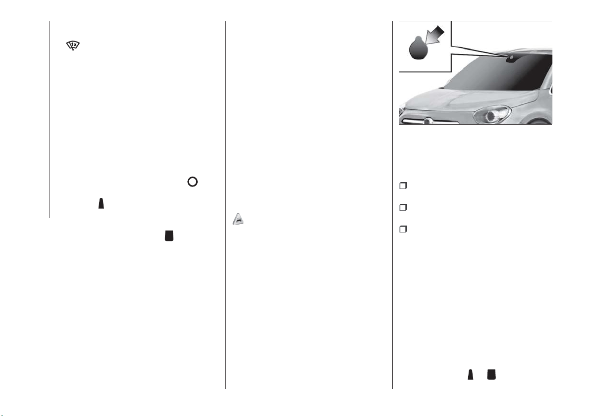
RAIN SENSOR
(where provided)
9) 10)
This is located behind the interior rear
view mirror fig. 34, in contact with the
windscreen and can measure the
amount of rain and, consequently,
manage the automatic wiping mode of
the windscreen in accordance with the
amount of water on the screen.
The rain sensor will be activated when
the ignition device is turned to MAR. If
no rain is detected, the wiper will not
carry out any strokes. If it is raining, the
windscreen wiper moves according to
the amount of rain measured by the
sensor.
The device is able to recognise, and
automatically adjust itself in the
presence of the following conditions:
presence of dirt on the surface (e.g.
salt, dirt, etc.);
presence of streaks of water caused
by the worn window wiper blades;
difference between day and night.
The rain sensor will be deactivated only
when the ignition device is turned to
STOP.
IMPORTANT Keep the glass in the
sensor area clean.
AUTOMATIC WIPING
Activation
The automatic wiping can be chosen by
selecting the rain sensor from the
display Menu or on the Uconnect™
system and rotating the ring nut A
fig. 33 to position
or .
34
F1B0048C
30
GETTING TO KNOW YOUR CAR
These will be used to set the sensitivity
level of the rain sensor: in position
,
the sensor has a lower sensitivity and
the windscreen wipers will activate
when there is a significant amount of
water on the windscreen; while in
position
, the windscreen wipers will
be activated by a minimum amount of
rain measured.
The activation of the automatic wiping
will be notified to the driver by a single
stroke.
The same stroke will be visible every
time the sensor sensitivity is increased,
by rotating the ring nut from position
to position .
The "Smart Washing" function activates
the normal washing cycle, after which
the automatic wiping function is
restored. The failure of the sensor is
indicated by the
symbol lighting up
on the display.
If the rain sensor malfunctions, the
wiper mode can be modified according
to requirements. The malfunction signal
remain active during the operation time
of the sensor or until the device is reset.
Inhibition
If the ignition device is turned to STOP,
leaving the ring nut A in position
or
, when the engine is next started
(ignition device at MAR), no wiping
cycle occurs for system protection
reasons.
This temporary inhibition prevents
unwanted activation of the wipers when
the car is started (i.e. when the
windscreen is being washed by hand or
the wipers are stuck to the windscreen
by ice).
It is possible to reactivate the automatic
wiping mode in three ways:
by rotating the ring nut to position O
and then again to position
or
by moving the stalk upwards to
position MIST
upon exceeding the 5 km/h speed
with the rain sensor
When the windscreen wiper is
reactivated using any of the
manoeuvres described above,
reactivation is indicated by a single
stroke of the windscreen wipers,
regardless of the condition of the
windscreen.
IMPORTANT For automatic
transmission vehicles with rain sensor,
engaging the gear N (Neutral) inhibits
the automatic wiping mode.
Deactivation
It is possible to deselect the automatic
wiping through the display Menu or the
Uconnect™ system, or by rotating ring
nut A to any non-intermittent position (
or ).
Service Position
The function allows the driver to replace
the windscreen wiper blades more
easily, protecting them also from ice
and/or snow.
Activation
To activate this function deactivate the
windscreen wiper (ring nut A fig. 33 in
position
) before setting the ignition
device to STOP. This function can only
be activated within 2 minutes of setting
the ignition device to STOP.
To activate this function, move the lever
upwards (unstable position) for at least
half a second.
Each time the function is activated
correctly, the wiper blades move to
signal the correct reception of the
command. The command can be
repeated up to a maximum of the three
times. The fourth repetition of the
command deactivates the function.
31
If, after using the function, the ignition
device is set back to MAR with the
blades in a position other than rest
position (at the base of the windscreen),
they will only return to rest position
following a command given using the
stalk (stalk upwards, into unstable
position) or when a speed of 5 km/h is
exceeded.
IMPORTANT Before activating the
function, make sure that when the
engine is turned on the windscreen
wiper is free of snow or ice
Deactivation
The function is deactivated if:
2 minutes have passed since the
ignition device was set to STOP;
the ignition device is set to MAR and
the blades are in rest position;
the ignition device is set to MAR and
a wiping command is carried out.
REAR WINDOW WIPER/
WASHER
Turn the ring B fig. 33 to set the
rearscreen wiper to operate in the
following modes:
continuous: when ring is in the
position;
intermittent: when ring is in the
position and the windscreen wiper is
stationary;
synchronous: when the rearscreen
wiper ring is in the
position and the
windscreen wiper is moving or set to
AUTO. In this mode, the rear window
wiper makes one stroke for each two
strokes of the windscreen wiper;
single wipe: with the selector in the
position, the windscreen wiper on
and reverse gear engaged.
Push the stalk towards the dashboard
(rocking position) to activate the rear
window washer jet. Keep pushing the
lever to automatically activate both the
rear window washer jet and the rear
window wiper with a single movement.
Releasing the stalk will activate three
strokes, as described for the
windscreen wiper. The smart wash
cycle will not be performed if the ring is
in the
position.
Deactivation
The function stops when the stalk is
released.
WARNING
20) If the window needs to be cleaned,
make sure the device is deactivated or the
ignition button and the key are on STOP.
IMPORTANT
7) Never use the windscreen wipers to
remove layers of snow or ice from the
windscreen. In such conditions, the
windscreen wiper may be subjected to
excessive stress and the motor cut-out
switch, which prevents operation for a few
seconds, may intervene. If operation is not
subsequently restored, even after restarting
the engine, contact a Fiat Dealership.
8) Do not operate the windscreen wiper
with the blades lifted from the windscreen.
9) Do not activate the rain sensor when
washing the car in an automatic car wash.
10) Make sure the device is switched off if
there is ice on the windscreen.
32
GETTING TO KNOW YOUR CAR
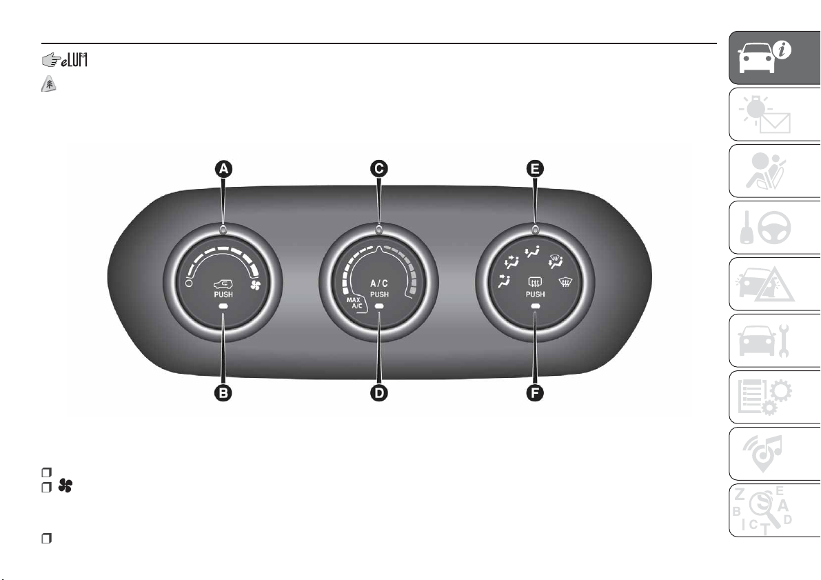
CLIMATE CONTROL SYSTEM
2)
MANUAL CLIMATE CONTROL SYSTEM
A - fan activation/adjustment knob:
0 = fan off
= fan speed (7 different speeds can be chosen)
B - air recirculation on/off button;
C - air temperature adjustment knob and MAX A/C function activation:
blue section = cold air
35
F1B0052C
33

red section = hot air
D - climate control system compressor activation/deactivation button (not available for versions with heater only);
E - air distribution knob:
air flow from central and side vents
air flow from central vents, side vents and front / rear footwell vents
air outlet from the front and rear footwell diffusers and a light air flow also from the side vents on the dashboard
air outlet from the front and rear footwell diffusers, to the windscreen, the side windows and a light air flow also at the side
vents on the dashboard
air outlet to the windscreen, the side windows and a light air flow also at the side vents on the dashboard
4 further intermediate positions are also possible in the 5 main distributions described above.
F - Heated rear window on/off button;
Selecting the windscreen air distribution activates the climate control system compressor (LED on A/C button on) and the air
recirculation is set to "outside air" (LED on button B off). This logic guarantees optimum visibility at the windows. The driver can
always set air recirculation and climate control system compressor.
Additional heater
(where provided)
The additional heater ensures more rapid passenger compartment heating.
It activates in cold weather conditions, if the following conditions are verified:
outside temperature low;
engine coolant temperature low;
engine started;
fan speed set at least to 1
st
speed;
knob C turned completely clockwise to red section.
The heater is switched off when at least one of the conditions above is no longer verified.
NOTE The power of the electric heater is modulated according to the battery voltage.
34
GETTING TO KNOW YOUR CAR
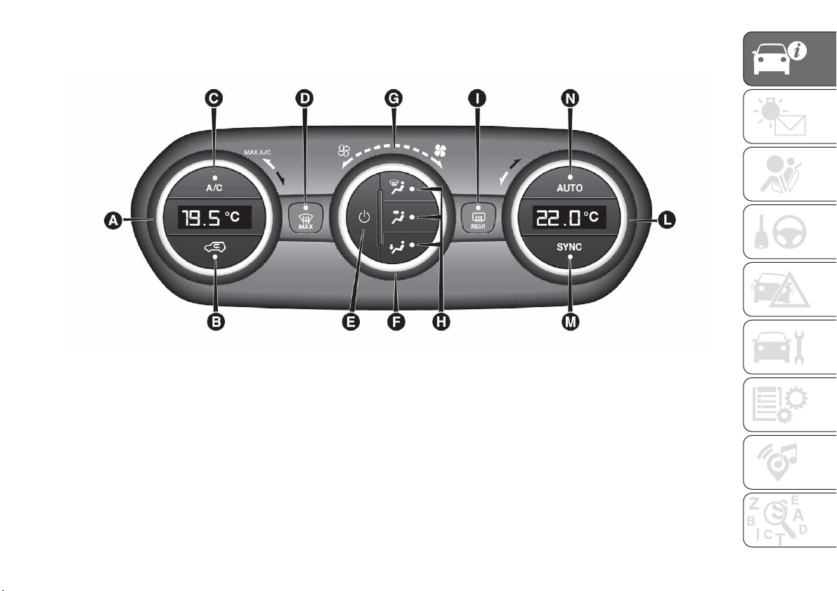
AUTOMATIC DUAL ZONE CLIMATE CONTROL SYSTEM
A - driver side temperature adjustment knob;
B - internal air recirculation on/off button;
C - climate control system compressor on/off button;
D - MAX-DEF function activation button (rapid defrosting/demisting of front windows);
E - climate control on/off button;
F - fan speed adjustment knob;
G - Fan speed indicator LED;
H - air distribution selection buttons;
I - Heated rear window on/off button;
36
F1B0051C
35
L - passenger side temperature adjustment knob;
M - SYNC function activation button (alignment of set temperatures) driver/passenger side;
N - AUTO function activation button (automatic operation).
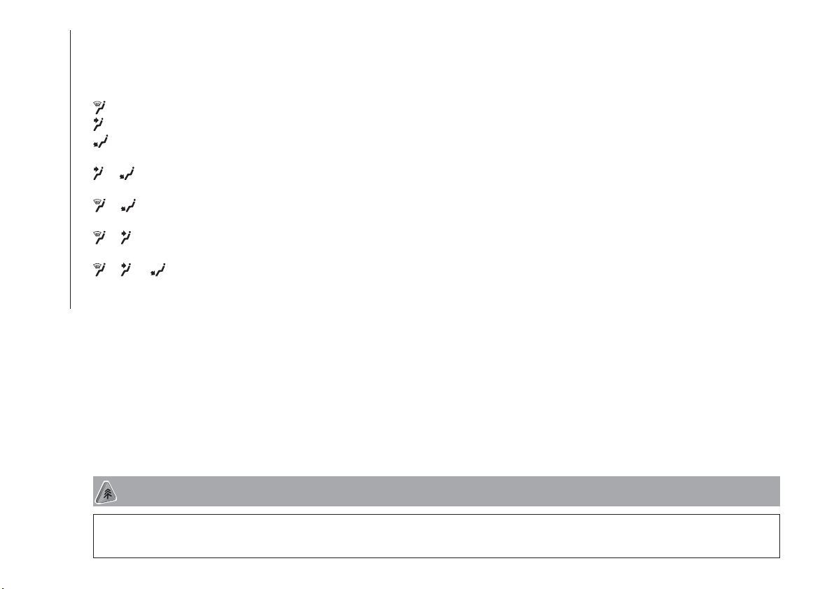
Air distribution selection
Air flow to the windscreen and front side window diffusers to demist/defrost them.
Air flow at central and side dashboard vents to ventilate the chest and the face during the hot season.
Air flow to the front and rear footwell diffusers. This air distribution setting heats the passenger compartment most quickly,
giving a prompt sensation of warmth.
+
Air flow distributed between footwell diffusers (hotter air) and central and side dashboard vents (cooler air). This
distribution setting is useful in spring and autumn on sunny days.
+
Air flow distributed between footwell vents and windscreen and front side vents. This distribution setting allows the
passenger compartment to be warmed up efficiently and prevents the windows from misting up.
+
Air flow distributed between central and side dashboard vents and windscreen and front side window vents. This
distribution allows air to be sent to the windscreen in conditions of strong sunlight.
+ +
Air flow distribution to all diffusers on the vehicle.
In AUTO mode, the climate control system automatically manages air distribution (the LEDs on buttons H are off). When set
manually, the air distribution is indicated by the LEDs on the selected buttons switching on. In combined function mode the
relevant function is enabled simultaneously with those already set by pressing the corresponding button. If a button whose
function is already active is pressed, its operation is cancelled and the corresponding LED switches off. To restore automatic
control of the air distribution after a manual selection, press the AUTO button.
Start&Stop
The automatic dual zone climate control system manages the Start&Stop system (engine off when vehicle speed is 0 km/h) to
ensure adequate comfort inside the vehicle. When the Start&Stop system is on (engine off and vehicle at a standstill), the
automatic recirculation management is turned off always taking air in from outside, to reduce the probability of the windows
misting up (as the compressor is off).
IMPORTANT
2) The system uses R134a coolant, which does not pollute the environment in the event of accidental leakage. Under no circumstances use
R1234yf and R12 fluids, which are incompatible with the components of the system.
36
GETTING TO KNOW YOUR CAR
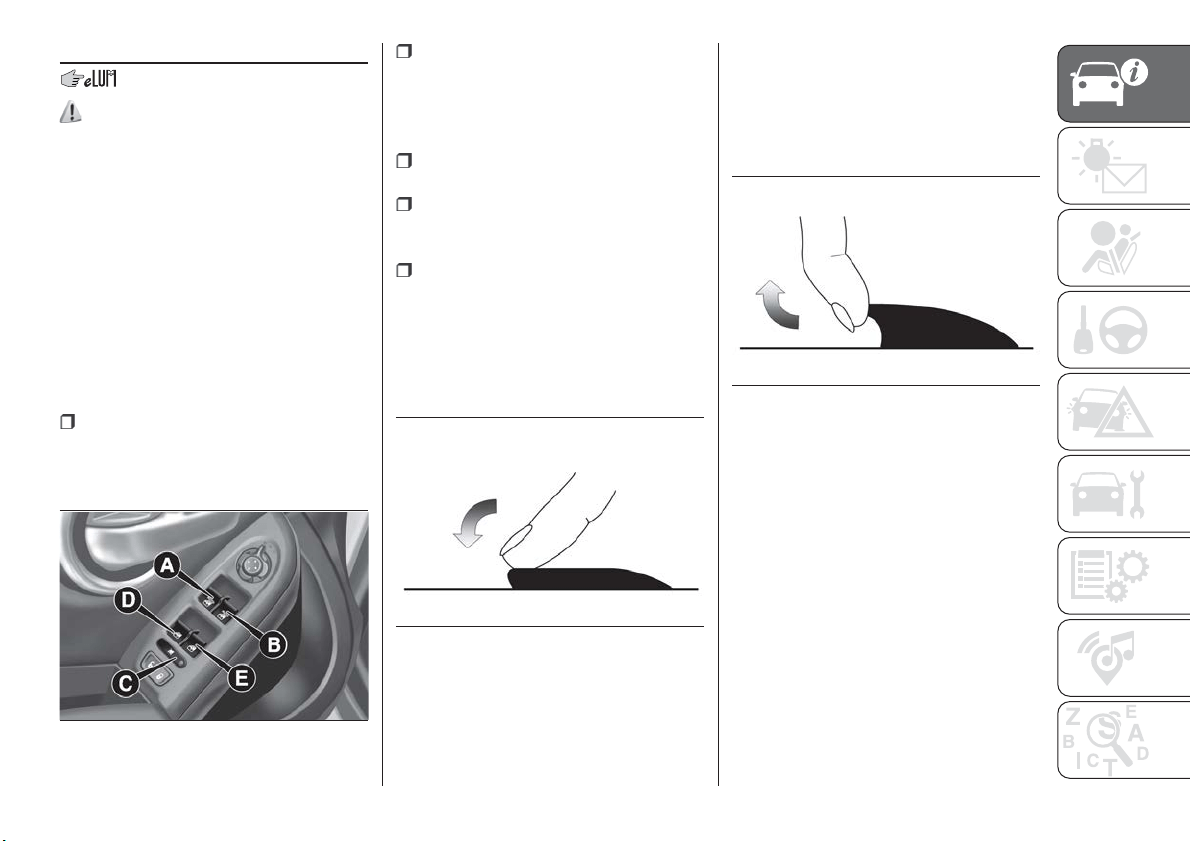
ELECTRIC WINDOWS
21)
Moving the windows up and down is
possible with the ignition device at MAR
and for about 3 minutes after the
ignition device switches to STOP (or
also after the mechanical key has been
extracted, for cars equipped with
mechanical key with remote control).
When one of the front doors is opened
this operation is disabled.
Driver side front door controls
All windows can be controlled from the
driver side door panel fig. 37.
A: front left window opening/closing.
"Continuous automatic" operation
during window opening/closing stage
and anti-pinch system activated.
B: right front window opening/
closing. "Automatic continuous"
operation during window
opening/closing and anti-pinch system
activated (where provided);
C: enabling/disabling of rear door
electric window controls;
D: left rear window opening/closing
(if present). "Automatic continuous"
mode for opening only;
E: right rear window opening/closing
(if present). "Automatic continuous"
mode for opening only.
Window opening
Push the buttons to open the desired
window fig. 38.
When any of the buttons on front or
rear doors is pressed briefly, the
window moves in stages; if the button
is held down, "continuous automatic"
operation is activated.
If the button is pressed again, the
window will stop in the desired position.
Window closing
Lift the buttons to close the desired
window fig. 39.
When any of the buttons on front or
rear doors is pressed briefly, the
window moves in stages; "continuous
automatic" operation is only available
for the front door windows.
The rear door windows can only be
closed in stages.
Front window anti-pinch safety
device
(where provided)
This safety system can recognise the
presence of any obstacle during the
window closing movement. If this
occurs, the system stops the window's
movement and reverts it, depending on
its position.
37
F1B0066C
38
F1B0067C
39
F1B0068C
37
The window is therefore lowered by
about 5 cm from its initial stop position.
The window cannot be operated in any
way during this time.
Electric window system
initialisation
If power supply is interrupted, the
electric window automatic operation
must be reinitialised.
The initialisation procedure described
below must be carried out with the
doors closed and for each door:
close the window by holding down
the button;
once the window has closed
completely, keep holding the button
down for at least a further 3 seconds.
WARNING
21) Incorrect use of the electric windows
may be dangerous. Before and during
operation, always check that nobody is
exposed to the risk of being injured either
directly by the moving window or through
objects getting caught or hit by it. When
leaving the vehicle (equipped with
mechanical key with remote control),
always remove the key from the ignition
device to prevent accidental operation of
the electric windows from being a hazard
for those still on board.
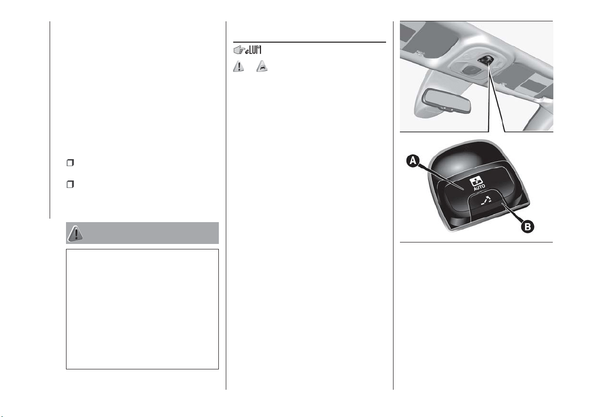
ELECTRIC SUN
ROOF
22) 11)
The electric sun roof comprises two
glass panels (the front one is mobile
and the rear one fixed) and is fitted with
two manually operated sun blinds.
Operation of the sun roof is only
possible with the ignition device at
MAR.
OPENING
Press button A fig. 40: the roof will
open up completely.
The automatic motion can be
interrupted in any position by pressing
button A again.
CLOSING
Press button A fig. 40: the roof will
close completely.
The automatic motion can be
interrupted in any position by pressing
button A again.
40
F1B0069C
38
GETTING TO KNOW YOUR CAR
SWIVEL OPENING
To bring the roof into "swivel" position,
press and release button B fig. 40.
This type of swivel-opening can be
activated irrespective of the position of
the sun roof. When starting with the
roof in closed position, pressing the
button automatically causes its
swivel-opening. If the roof is already
open, the button must be held until the
roof reaches the swivel-opening
position.
Pressing button B again during
automatic movement of the roof will
stop it.
SUN BLIND MOVEMENT
The blind is manually-operated: it can
be stopped in any position.
ANTI-PINCH DEVICE
The sun roof has an anti-pinch safety
system capable of detecting the
presence of an obstacle during the
closing movement: if this happens, the
system intervenes and the movement of
the roof is immediately reversed into
opening.
EMERGENCY OPERATION
If the control buttons fail to operate, the
sun roof can be moved manually,
proceeding as described below:
remove protective cap A fig. 41 on
the internal trim;
take Allen key B provided;
place Allen key B into housing A;
turn Allen key B in a clockwise
direction to open the roof or in an
anticlockwise direction to close it.
INITIALISATION
PROCEDURE
After irregular behaviour of the sun roof
or an emergency manoeuvre (see
description in the previous paragraph),
the automatic operation of the sun roof
must be initialised again.
Proceed as follows:
press button A fig. 40 to bring the
roof into completely closed position;
bring the ignition device to STOP
and wait at least 10 seconds;
bring the ignition device to MAR;
hold button A down for at least
10 seconds, then you should hear the
mechanical stop of the roof motor;
within 5 seconds hold button A
down: the roof will perform a complete
automatic opening and closing cycle (to
indicate that the initialisation procedure
has been successful). If this does not
occur, the procedure must be restarted
from the beginning.
WARNING
22) When leaving the vehicle, always
remove the key (where present) from the
ignition to avoid the risk of injury due to
accidental operation of the sun roof.
Improper use of the roof can be
dangerous. Before and during operation,
always check that no-one is exposed to
the risk of being injured by the moving
sunroof or by objects getting caught or hit
by it.
IMPORTANT
11) Do not open the sun roof if a roof rack
or crossbars are fitted. Do not open the
sun roof if there is snow or ice on it: you
may damage it.
41
F1B0070C
39
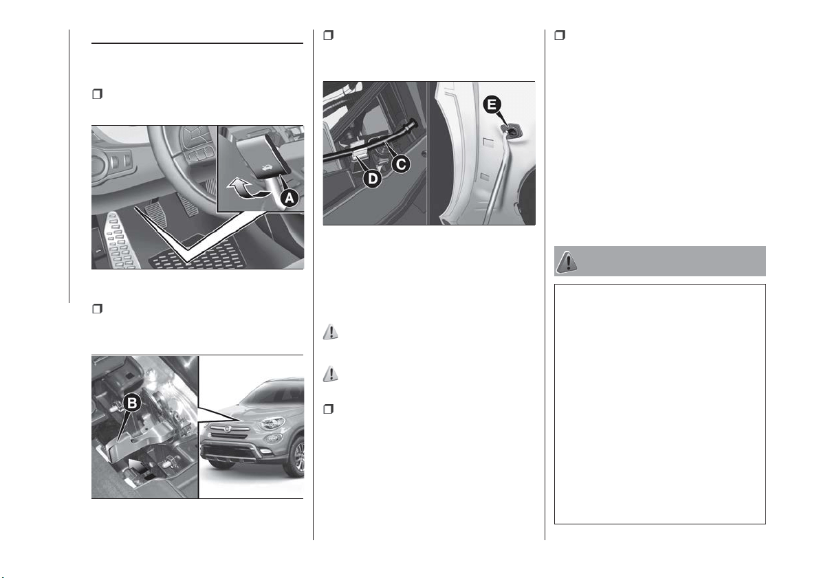
BONNET
OPENING
Proceed as follows:
pull lever A fig. 42 in the direction
indicated by the arrow;
operate lever B fig. 43, in the
direction indicated by the arrow, and
raise the bonnet;
release bonnet stay C fig. 44 from its
locking device D, then insert its end in
housing E on the bonnet.
IMPORTANT Before raising the bonnet,
make sure that the arms of the wipers
are not raised from the windscreen and
that the wiper is not operational.
23) 24) 25)
CLOSING
26)
Proceed as follows:
hold the bonnet up with one hand
and with the other remove the stay C
fig. 44 from the housing E and fit it back
in the locking device D;
lower the bonnet to approximately
40 centimetres from the engine
compartment and let it drop. Make sure
that the bonnet is completely closed
and not only fastened by the locking
device by trying to open it. If it is not
perfectly closed, do not try to press the
bonnet lid down but open it and repeat
the procedure.
IMPORTANT Always check that the
bonnet is closed correctly to prevent it
from opening while the vehicle is
travelling.
WARNING
23) Perform these operations only when
the car is stationary.
24) The bonnet may drop suddenly if the
supporting rod is not positioned correctly.
25) Use both hands to lift the bonnet.
Before lifting, check that the windscreen
wiper arms are not raised from the
windscreen, that the vehicle is stationary
and that the electric parking brake is
engaged.
26) For safety reasons, the bonnet must
always be properly closed while the car is
travelling. Therefore, make sure that the
bonnet is properly closed and that the lock
is engaged. If you discover that the bonnet
is not perfectly closed during travel, stop
immediately and close the bonnet in the
correct manner.
42
F1B0500C
43
F1B0072C
44
F1B0073C
40
GETTING TO KNOW YOUR CAR
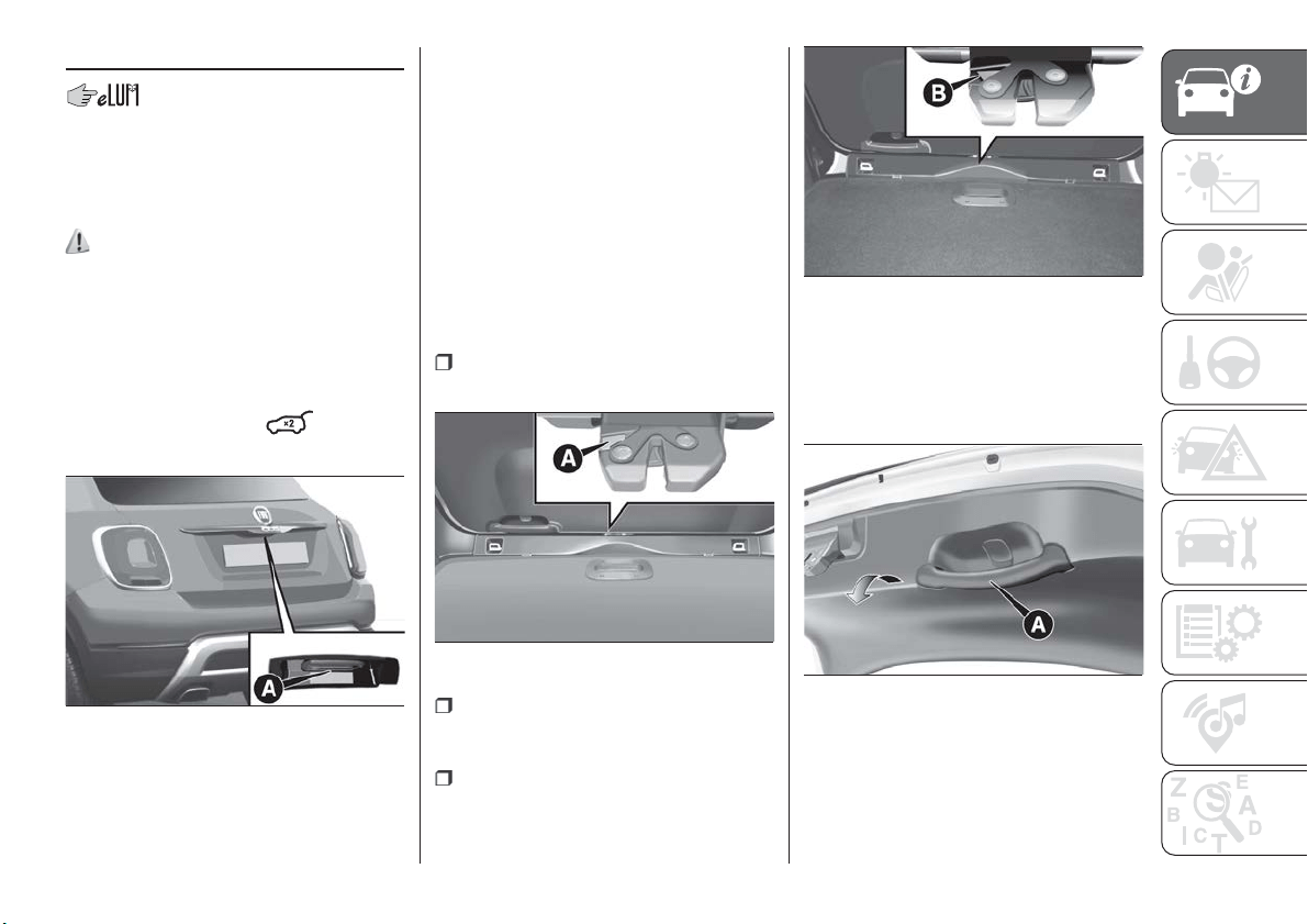
BOOT
The boot unlocking is electrically
operated and is deactivated when the
vehicle is in motion.
OPENING
27)
Opening from the outside
When unlocked, the tailgate can be
opened from outside the vehicle using
the electric opening handle A
fig. 45 located under the handle until
the unlocking click is heard or by
quickly pressing button
on the
remote control twice.
The direction indicators will blink twice
and the internal roof light will
simultaneously come on when the boot
is opened; the roof light will
automatically switch off when the
tailgate is closed (see also "Interior
lights").
If the tailgate is left open, the roof light
will automatically switch off to preserve
the battery charge.
Emergency opening from the inside
Proceed as follows:
lower the head restraints and fold the
backrests;
identify and remove yellow guard A
fig. 46, which is press-fitted on the lock,
using the screwdriver provided;
insert the screwdriver in order to
activate tab B fig. 47, for mechanical
release of the lock.
CLOSING
Grip handle A fig. 48 and lower the
tailgate, pressing next to the lock until it
clicks.
IMPORTANT Before closing the boot
make sure that you have the keys since
the boot is automatically locked.
45
F1B0074C
46
F1B0075C
47
F1B0076C
48
F1B0077C
41
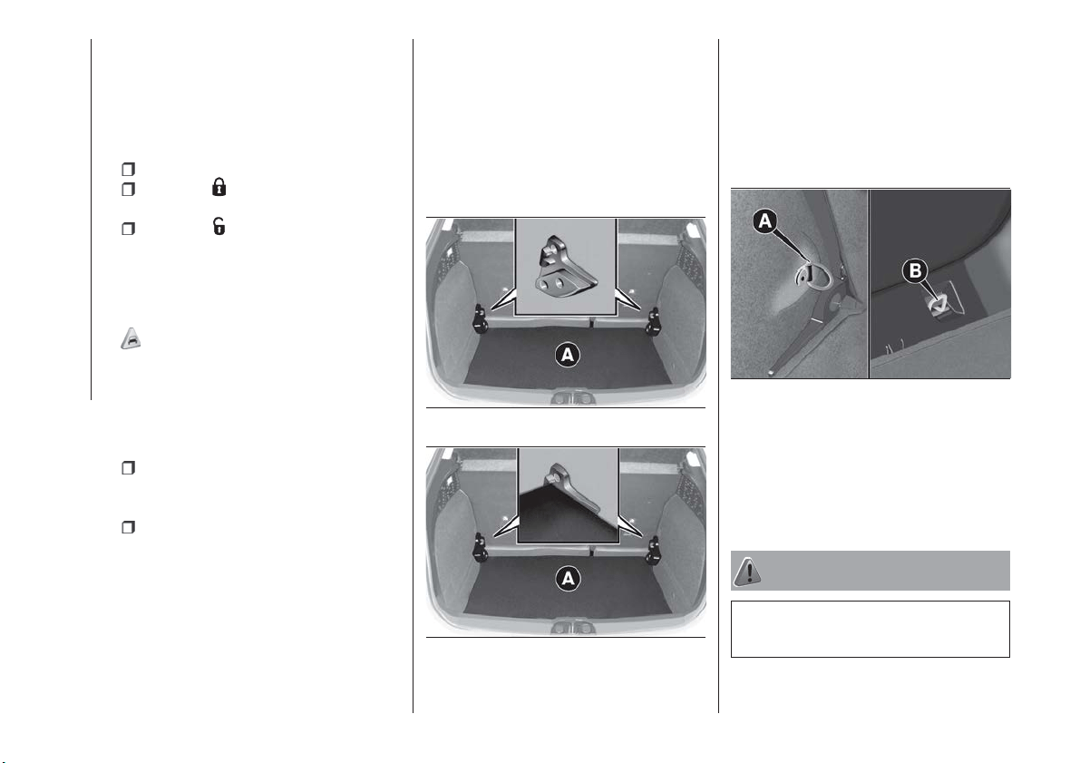
BOOT INITIALISATION
IMPORTANT If the battery is
disconnected or the protection fuse
blows, the boot opening/closing
mechanism must be reinitialised as
follows:
close all the doors and the boot;
press the " FIAT" button on the
remote control;
press the button on the remote
control.
LOAD COMPARTMENT
FEATURES
Reconfigurable load platform
12)
The car is equipped with a
reconfigurable load platform A, which
makes the boot volume modular:
The load platform can be set to
2 different positions:
Floor level (low) fig. 49: allows use
of the full luggage compartment
capacity.
Sill level (high) fig. 50: combined
with folding the rear seats and front
passenger seat, it allows long items to
be loaded and also makes
loading/unloading items in the luggage
compartment easier. It also allows the
space underneath (double bottom) to
be used as a further compartment for
stowing objects which are more fragile
or small.
The load platform can also be tilted,
and is equipped with a washable plastic
surface, useful for instance for
transporting wet or muddy items.
IMPORTANT Movements of the load
platform must take place in a central
position relative to the luggage
compartment.
Anchoring your load
Four hooks may be arranged in the
corners of the boot, according to the
versions, at the corners of the boot (two
at the front A fig. 51 and two at the rear
B ) for attaching cables for firmly
securing the carried load.
EMERGENCY KIT
(where provided)
Inside the kit, located in the luggage
compartment, are a fire extinguisher
and a first-aid bag.
WARNING
27) Be careful not to hit objects on the
storage shelf when you open the tailgate.
49
F1B0327C
50
F1B0328C
51
F1B0079C
42
GETTING TO KNOW YOUR CAR
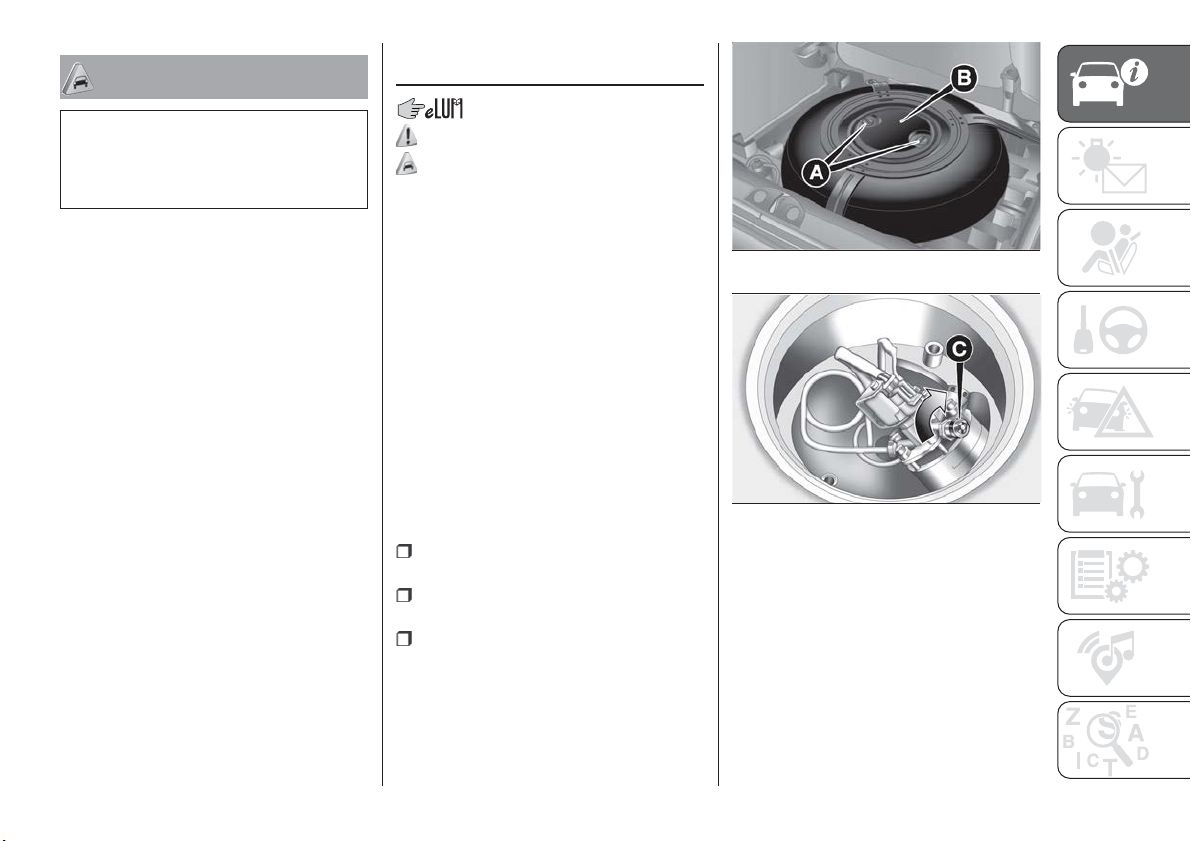
IMPORTANT
12) The dimensions of the platform permit
a maximum distributed weight capacity of
70 kg: do not load objects with a greater
weight.
VERSION WITH LPG
SYSTEM
28) 29)
13) 14) 15)
INTRODUCTION
The LPG version features two fuel
supply systems: one for petrol and one
for LPG.
Like the petrol system, the LPG system
is timed, sequential multipoint type with
special injectors.
PASSIVE SAFETY /
ACTIVE SAFETY
Although the LPG system has
numerous safety features, it is advisable
to proceed as follows every time the car
is not in use for a long period or moved
in an emergency as a result of a
breakdown or accident:
unscrew the fixing devices A
fig. 52 and then remove the cover B;
close the LPG cock rotating the ring
C fig. 53 clockwise;
refit the cover and retighten the
fastening devices.
52
F1B0602C
53
F1B0270C
43
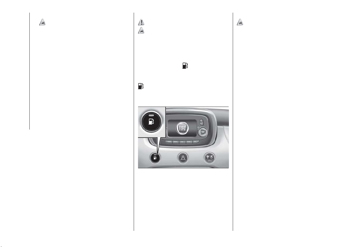
LPG TANK
16)
The car has a pressurised tank for
storing LPG in a liquid state. It is
toroidal and is located in the spare
wheel compartment with suitable
protection.
LPG tank certification
The LPG tank is certified in
accordance with the regulations in
force.
In Italy, the tank has a life of
10 years starting from the car
registration date. If the car has
been registered in a country other
than Italy, the duration and the
testing/inspection procedures of
the LPG tank can vary depending
on the national provisions in force
in that country. In all case, when the
time limit for your country has
expired, go to a Fiat Dealer to have
the tank replaced.
LPG/PETROL SWITCH
30)
18) 19) 20)
This engine normally runs on LPG
except during starting when it runs on
petrol.
Switching to LPG is automatic: the
green warning light
on the
instrument panel turns off.
To change fuel type, press the
button on the dashboard fig. 54with
the car stationary and engine running,
or while driving.
If the LPG runs out during LPG
operation, the system automatically
switches over to running on petrol.
The four bars on the digital indicator
near the letters LPG on the instrument
panel indicate the level of LPG in the
tank.
REFUELLING
17) 21) 22) 23)
LPG
Maximum refuelling capacity (including
reserve) (*): 38 litres
(*) The figure already takes into account
the 80% tank filling limit and the
residual fluid required for priming; it is
the maximum permitted capacity. In
addition, after different refuelling
processes, this figure may vary due to
differences between the network pump
supply pressures, pumps having
different supply/locking features, tank
not completely run out of fuel.
Note that when using a fuel such as
LPG, the range is very variable
because, in addition to the vehicle
driving and servicing conditions, it also
depends on the composition of the gas
which may vary, not only seasonally, but
also from supplier to supplier. LPG is, in
effect, a composition of gas (butane
and propane) mixed in a way that may
not be standardised.
IMPORTANT In order to avoid
inconsistent information by the LPG
gauge on the instrument panel, it is
recommended to refill with at least
10 litres each time.
54
F1B0611C
44
GETTING TO KNOW YOUR CAR
WARNING
28) Note that in some countries (including
Italy) there are legal restrictions in force for
parking/garaging motor cars fuelled by gas
that is denser than air; LPG comes under
this category.
29) If gas is smelt, switch from LPG
operation to petrol operation and
immediately go to a Fiat Dealership to have
the vehicle checked and possible system
faults excluded.
30) Do not switch between the two
operating modes whilst starting the engine.
IMPORTANT
13) The car is equipped with a specifically
designed gaseous LPG injection system: it
is therefore absolutely forbidden to alter the
configuration of the system or its
components. The use of other components
or materials could cause malfunctions and
lead to a reduction in safety; therefore, in
the case of problems, contact a Fiat
Dealership. When towing or lifting the
vehicle, follow the instructions in the main
handbook under the paragraph on "Towing
the vehicle" to prevent damage to the gas
system parts.
14) When painting in an oven, the LPG tank
must be removed from the car and later
refitted by a Fiat Dealership.
15) The system operates at temperatures
ranging between -20°C and 100°C.
16) Periodically (at least once every six
months), it is advisable to let the LPG in the
tank run out and, at the next refuelling,
check that it does not exceed the
maximum capacity of 38 litres (reserve
included) (with a tolerance of 2 litres
excess) (see instructions in the "Capacities"
paragraph of this supplement). If the level is
above 38 litres (reserve included) contact a
Fiat Dealership immediately.
17) It is strictly forbidden to use any
additive in the LPG. Periodically (at least
once every six months) it is advisable to let
the LPG in the tank run out and, at the first
refuelling, to check that it does not exceed
the maximum capacity of 42 litres (reserve
included) (with a tolerance of 1 litres
excess). If the level is above 42 litres
(reserve included) contact a Fiat Dealership
immediately.
18) Regardless of the last fuel system used,
at the following engine starting, after the
initial petrol stage, the system will
automatically switch to LPG.
19) When switching is requested, metallic
noise from the valves which pressurise the
circuit can be heard. For the switching logic
described above, a delay between the
valve ticking and the switching off of the
instrument panel indication is completely
normal.
20) In particular usage conditions, such as
starting and operation at low ambient
temperature or LPG supply with low
propane content, the system may switch
temporarily to petrol operation, without a
visual indication of switching on the
instrument panel. In the event of low LPG
levels in the tank or request for high
performance (e.g. overtaking, car fully
laden, steep hills) the system may
automatically switch to petrol operation to
guarantee the engine power requested; the
green warning light
on the instrument
panel switches on to indicate this. When
the above conditions are no longer present,
the system automatically restores LPG
operation; the green warning light
switches off. To achieve the automatic
switching described above, make sure that
there is always enough fuel in the petrol
tank.
21) Only use LPG for motor vehicles.
22) It is strictly forbidden to use any
additive in the LPG.
23) Periodically (at least once every six
months), it is advisable to let the LPG in the
tank run out and, at the next refuelling,
check that it does not exceed the
maximum capacity of 38 litres (reserve
included) (with a tolerance of 2 litres
excess) (see instructions in the "Capacities"
paragraph of this supplement). If the level is
above 38 litres (reserve included) contact a
Fiat Dealership immediately.
45

KNOWING THE INSTRUMENT PANEL
This section of the booklet gives you all
the information you need to
understand, interpret and use the
instrument panel correctly.
CONTROL PANEL AND
ON-BOARD INSTRUMENTS ......47
DISPLAY ..................49
TRIP COMPUTER.............51
WARNING LIGHTS AND
MESSAGES ................52
46
KNOWING THE INSTRUMENT PANEL
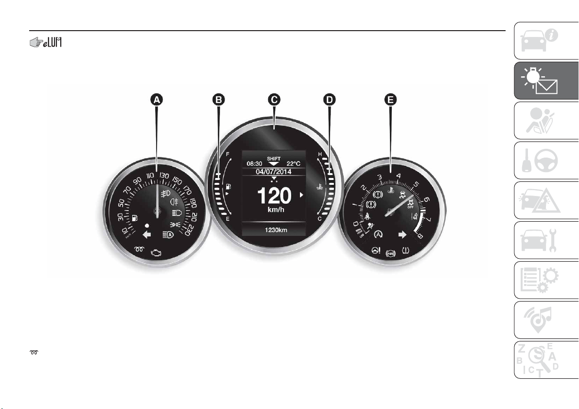
CONTROL PANEL AND ON-BOARD INSTRUMENTS
VERSIONS WITH MONOCHROME DISPLAY
A. Speedometer / B. Digital fuel level gauge and reserve war ning light / C. Display / D. Digital engine coolant thermometer with
overheating warning light / E. Tachometer.
For LPG versions: the temperature indicator D is replaced by the LPG fuel level and the “Coolant temperature” is shown on the
instrument panel display.
Warning light present on Diesel versions only.
IMPORTANT The illumination of the instrument panel graphics may vary according to version.
55
F1B0341C
47
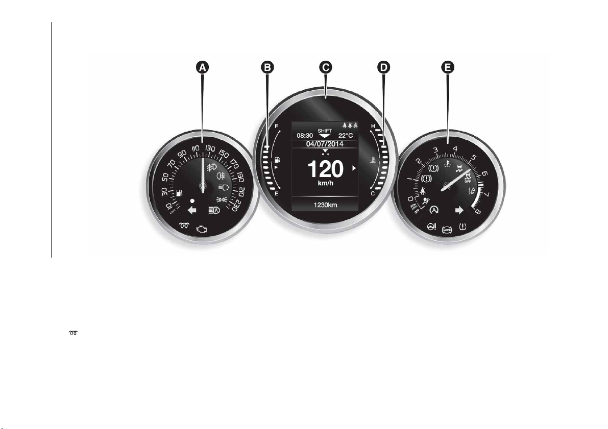
VERSIONS WITH COLOUR DISPLAY
A. Speedometer / B. Digital fuel level gauge and reserve war ning light / C. Display / D. Digital engine coolant thermometer with
overheating warning light / E. Tachometer
For LPG versions: the temperature indicator D is replaced by the LPG fuel level and the “Coolant temperature” is shown on the
instrument panel display.
Warning light present on Diesel versions only.
IMPORTANT The illumination of the instrument panel graphics may vary according to version.
56
F1B0342C
48
KNOWING THE INSTRUMENT PANEL
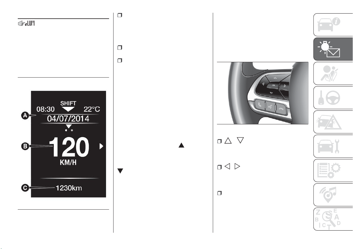
DISPLAY
DESCRIPTION
The vehicle is equipped with a display
that can show useful information to the
driver while driving.
The display fig. 57 will show the
following information:
A: time, Gear Shift Indicator (where
provided), gear engagement (versions
with automatic transmission only),
outside temperature, compass
indications (where provided), date.
B: vehicle speed, warning
messages/any failure indications.
C: total kilometres (or miles) run and
icons of any failure indications.
GEAR SHIFT INDICATOR
(where provided)
The Gear Shift Indicator (GSI) system
advises the driver when to change gear
through a special indication on the
display
Through the GSI, the driver is informed
that the gear change will allow a
reduction in fuel consumption to be
obtained.
When the SHIFT UP icon (
SHIFT) is
shown on the display, the GSI is
advising the driver to engage a higher
gear, while the SHIFT DOWN (
SHIFT) icon advises the driver to
engage a lower gear.
The indication in the display remains
until a gear is shifted or the driving
conditions go back to a situation where
gearshifting is not required to improve
consumption.
CONTROL BUTTONS
These are located on the left side of the
steering wheel fig. 58.
They allow the driver to select and
interact with the items in the Main menu
of the display (see paragraph "Main
menu").
/ : press and release the
buttons to access the Main menu and
to scroll the menu and the submenus
upwards or downwards.
/ : press and release the
buttons to access the information
displays or the submenus of an item of
the Main menu.
OK: press this button to
access/select the info displays or the
submenus of an item of the Main menu.
Hold the button pressed for 1 second
to reset the displayed/selected
functions.
57
F1B0179C
58
F1B0183C
49
MAIN MENU
The Menu includes the following items:
TRIP
MOOD SELECTOR (or DRIVE MODE
depending on the market) (where
provided) / GSI
VEHICLE INFO
DRIVER ASSIST
AUDIO
PHONE
NAVIGATION
ALERTS
VEHICLE SET-UP
Vehicle setup (Change car settings)
This menu item allows you to change
the settings for:
"Vehicle off" (where provided);
"Display";
"Units";
"Clock & Date";
"Security"
"Security & Assistance";
"Lights";
"Doors & Locks".
“Vehicle off” (where provided)
This is used to switch off the engine in
the event of a Keyless Enter-N-Go
system fault, following the procedure
described on the display.
Display
By selecting item "Display" you can
access the settings/information
regarding: "Language", "See phone",
"See navigation", "Automatic Trip B
reset", "Drive Mode Repeat" (or “Mood
Selector Repeat” depending on the
market) (where provided), "Display
settings".
"Units"
Select item "Units" to choose the unit of
measurement between: "Imperial",
"Metric", "Custom".
"Clock & Date"
Select item "Clock & Date" to make the
following adjustments: "Set time", "Time
format", "Set date".
"Security"
Select item "Security" to make the
following adjustments: "Passenger
AIRBAG", "Speed beep", "Seat belt
buzzer", "Hill Hold Control".
"Passenger AIRBAG" adjustment allows
you to activate/deactivate the
passenger airbag:
Passenger's protection active:
the
ON LED comes on constantly in
the instrument panel dashboard.
Passenger's protection not
active: the
OFF LED comes on
constantly in the instrument panel
dashboard.
"Security & Assistance"
For possible adjustments see
paragraph Uconnect™ in the
dedicated chapter.
"Lights"
Select item "Lights" to make the
following adjustments: "Interior Ambient
lighting", "Headlight sensor", "Follow
me", "Headlights while opening", "Auto
high beams", "Daytime Lights",
"Cornering lights".
"Doors & Locks"
Select item "Doors & Locks" to make
the following adjustments: "Autoclose",
"Aut. unl. on exit", "Flsh.Light w/Lock",
"Horn with Lock", "Horn with remote
start", "Remote unlock", "Door Unlock"
(versions with Keyless Entry), "Keyless
Entry".
NOTE With the Uconnect™ system,
some Menu items are shown and
managed on the display of the latter
and not on the instrument panel display
(refer to the Multimedia chapter or to
the supplement available online).
50
KNOWING THE INSTRUMENT PANEL
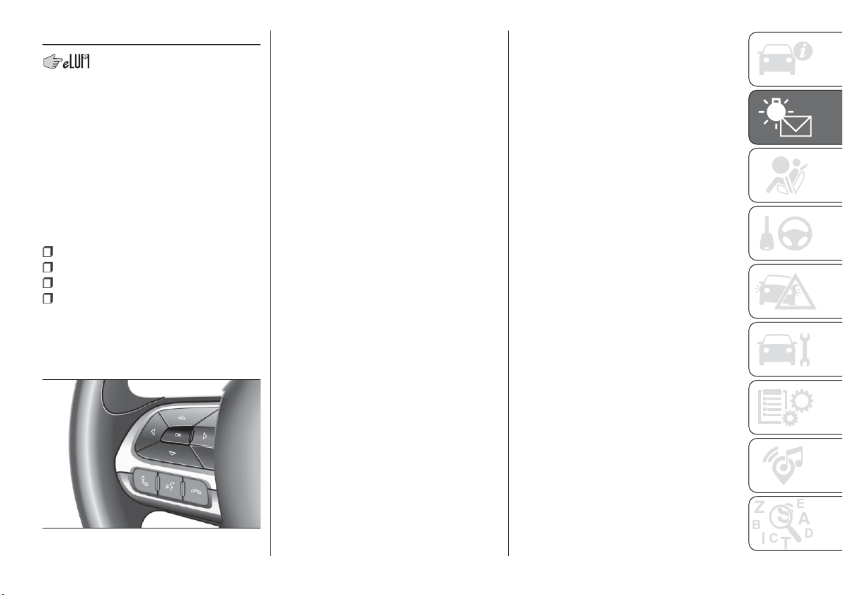
TRIP COMPUTER
The "Trip computer" is used to display
information on vehicle operation when
the ignition device is at MAR.
This function is characterised by two
separate memories, called "Trip A" and
"Trip B", where the vehicle's "complete
missions" (journeys) are recorded in a
reciprocally independent manner.
“Trip A” and “Trip B” are used to display
the values relating to:
Distance travelled
Average fuel consumption
Average speed
Trip time (driving time)
On LPG versions, the “Range”,
“Average consumption” and
“Instantaneous consumption” values
are available for both petrol and LPG.
To reset the values, press and hold
down the OK fig. 59 button on the
steering wheel.
NOTE "Range" and "Instant
consumption" values cannot be reset.
59
F1B0184C
51
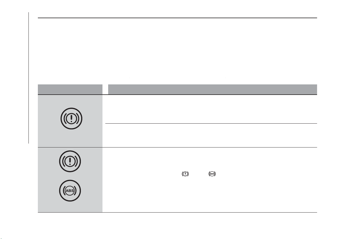
WARNING LIGHTS AND MESSAGES
IMPORTANT The war ning light switches on in the instrument panel together with a dedicated message and/or acoustic signal
when applicable. These indications are indicative and precautionary and as such must not be considered as exhaustive and/or
alternative to the information contained in the Owner Handbook, which you are advised to read carefully in all cases. Always
refer to the information in this chapter in the event of a failure indication.
IMPORTANT Failure indications displayed are divided into two categories: serious and less serious failures. Serious failures are
indicated by a repeated and prolonged warning "cycle". Less serious failures are indicated by a warning "cycle" with a shorter
duration. The display cycle of both categories can be interrupted. The instrument panel warning light will stay on until the cause
of the failure is eliminated.
Warning light What it means
red
INSUFFICIENT BRAKE FLUID / ELECTRIC PARKING BRAKE ON
Low brake fluid level
The warning light turns on when the level of the brake fluid in the reservoir falls below the minimum level,
possibly due to a leak in the circuit. Restore the brake fluid level, then check that the warning light has
switched off. If the warning light stays on, contact a Fiat Dealership.
Electric parking brake on
The warning light switches on when the electric parking brake is engaged. Release the electric parking
brake, then check that the warning light has switched off. If the warning light stays on, contact a Fiat
Dealership.
red
yellow
EBD FAILURE
The simultaneous switching on of the
(red) and (amber) warning lights with the engine on indicates
either a failure of the EBD system or that the system is not available. In this case, the rear wheels may
suddenly lock and the vehicle may swerve when braking sharply.
Drive very carefully to the nearest Fiat Dealership to have the system inspected immediately.
52
KNOWING THE INSTRUMENT PANEL
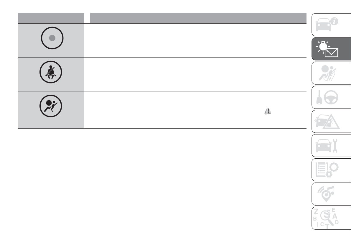
Warning light What it means
red
ELECTRONIC ALARM
The warning light turns on when the electronic alarm is activated (deterrent function).
red
SEAT BELTS REMINDER
The warning light switches on constantly if the car is stationary and the driver side and/or passenger side
seat belt (with passenger seated) is not fastened. The warning light flashes and an acoustic warning will
sound if the car is in motion and the driver side and/or passenger side seat belt (with passenger seated) is
not correctly fastened. Fasten the seat belt.
red
AIR BAG FAILURE
If the warning light switches on constantly, this indicates a failure in the airbag system.
31) 32)
53
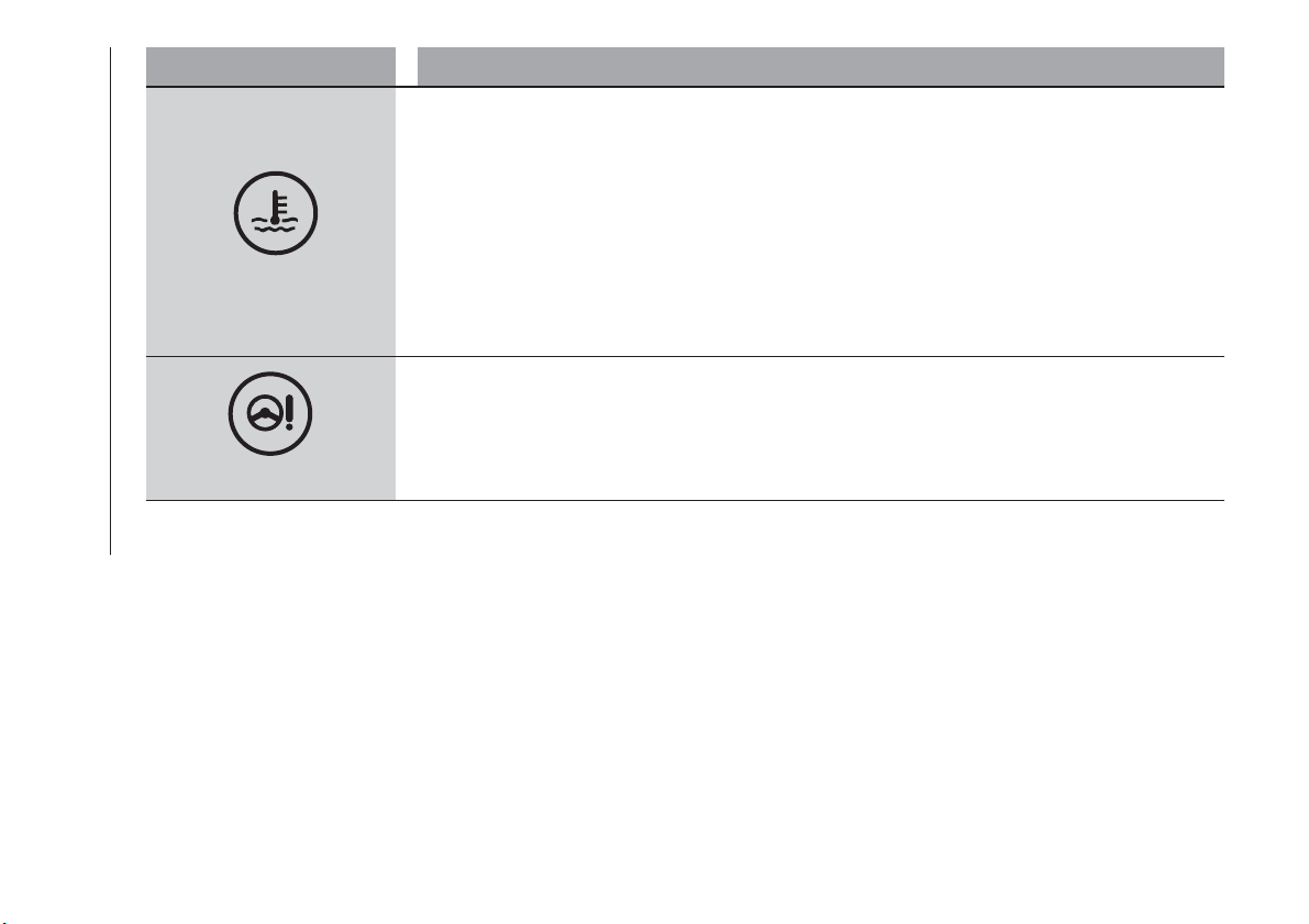
Warning light What it means
red
ENGINE COOLANT TEMPERATURE TOO HIGH
The warning light (or the icon on the display on some versions) switches on when the engine is overheated.
In normal driving conditions: stop the car, stop the engine and check that the water level in the reservoir
is not below the MIN mark. In this case, wait for the engine to cool down, then slowly and carefully open
the cap, top up with coolant and check that the level is between the MIN and MAX marks on the reservoir
itself. Also check visually for any fluid leaks. If, when restarting, the warning light switches on (or the icon is
displayed) again, contact a Fiat Dealership.
If the vehicle is used under demanding conditions (e.g. in high-performance driving): slow down and,
if the warning light stays on, stop the vehicle. Stop for two or three minutes with the engine running and
slightly accelerated to facilitate better coolant circulation, then turn the engine off. Check that the coolant
level is correct as described above.
IMPORTANT Over demanding routes, it is advisable to keep the engine running and slightly accelerated for
a few minutes before turning it off.
red
POWER STEERING FAILURE
This warning light (or symbol in the display) switches on when the ignition device is brought to MAR, but it
should switch off after a few seconds. If the warning light (or symbol on the display) remains on, you could
not have steering assistance and the effort required to operate the steering wheel could be increased;
steering is, however, possible. On some versions the display shows the dedicated message. Contact a Fiat
Dealership as soon as possible.
54
KNOWING THE INSTRUMENT PANEL
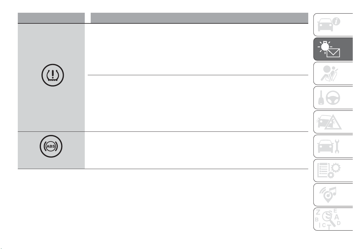
Warning light What it means
yellow
iTPMS
iTPMS failure
When an iTPMS system failure is detected, the light flashes for 75 seconds, then stays on and a warning
message appears. This also happens if there are one or more wheels without sensors, until initial
conditions are restored.
IMPORTANT Do not continue driving with one or more flat tyres as handling may be compromised. Stop
the vehicle, avoiding sharp braking and steering. Repair immediately using the dedicated tyre repair kit (see
the “Fix&Go Automatic kit” paragraph in the "In an emergency" chapter) and contact a Fiat Dealership as
soon as possible.
Tyre pressure low
The warning light switches on and a message is displayed to indicate that the tyre pressure is lower than
the recommended value and/or that slow pressure loss is occurring. In these cases, optimal tyre duration
and fuel consumption may not be guaranteed.
In any situation in which the dedicated message is shown on the display, it is ESSENTIAL to refer to the
contents of the "Wheels" paragraph in the "Technical data" chapter, strictly complying with the indications
that you find there.
Once the normal operating conditions of the car are restored, carry out the "Reset" procedure.
WARNING Do not continue driving with one or more flat tyres as the car handling may be compromised.
Stop the vehicle, avoiding sharp braking and steering.
yellow
ABS FAILURE
The warning light switches on to indicate an ABS fault. In this case the braking system maintains its
efficiency unaltered but without the advantage of the ABS system. Drive carefully and contact a Fiat
Dealership as soon as possible.
55
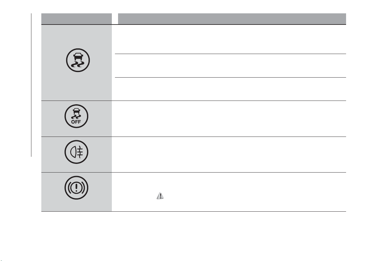
Warning light What it means
yellow
ESC SYSTEM
ESC system activation
Intervention by the system is indicated by the flashing of the warning light: it indicates that the car is in
critical stability and grip conditions.
ESC system failure
If the warning light does not switch off, or if it stays on with the engine running, a failure was found on the
ESC system. Contact a Fiat Dealership as soon as possible.
Hill Hold Control system failure
The warning light switches on and the displays shows the dedicated message, indicating Hill Hold Control
system failure. Contact a Fiat Dealership as soon as possible.
yellow
PARTIAL / TOTAL DEACTIVATION OF ACTIVE SAFETY SYSTEMS
The turning on of the warning light indicates that some safety systems have been partially deactivated by a
driver's request.
yellow
REAR FOG LIGHT
The warning light switches on when the rear fog light is activated.
yellow
ELECTRIC PARKING BRAKE FAILURE
The warning light switches on when electric parking brake failure is detected. Contact a Fiat Dealership as
soon as possible.
33)
56
KNOWING THE INSTRUMENT PANEL
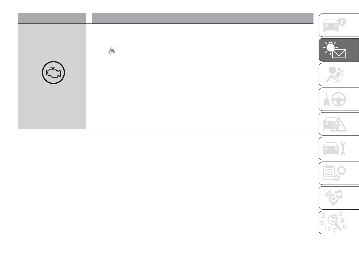
Warning light What it means
yellow
INJECTION / EOBD SYSTEM FAILURE
In normal conditions, when the ignition device is brought to MAR, the warning light switches on, but it
should switch off as soon as the engine is started. The operation of the warning light may be checked by
the traffic police using specific devices. Comply with the laws and regulations of the country where you are
driving.
24)
Injection system failure
If the warning light remains on, or it switches on whilst driving, the injection system is not working properly.
The warning light on constantly signals a malfunction in the supply/ignition system which could cause high
exhaust emissions, a possible loss of performance, poor driveability and high consumption. On some
versions the display shows the dedicated message. The war ning light switches off if the malfunction
disappears, but is still stored by the system. Under these conditions, the vehicle can continue travelling at
moderate speed but without demanding excessive effort from the engine or high speed. Prolonged use of
the car with the warning light on may cause damage. Contact a Fiat Dealership as soon as possible.
Catalytic converter damaged
If the warning light flashes, it means that the catalytic converter may be damaged. Release the accelerator
pedal to lower the speed of the engine until the warning light stops flashing. Continue the journey at
moderate speed, trying to avoid driving conditions that may cause further flashing and contact a Fiat
Dealership as soon as possible.
57
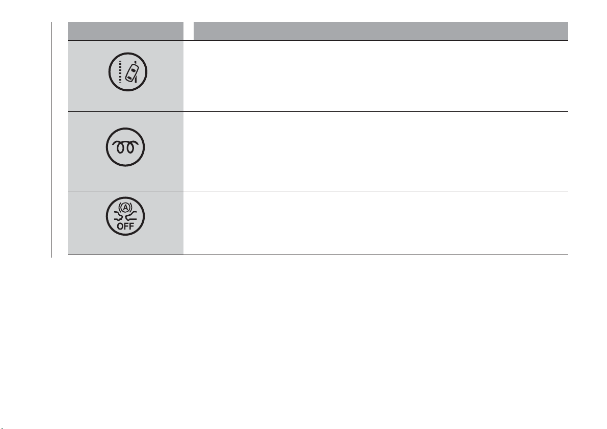
Warning light What it means
yellow
LANE ASSIST SYSTEM
The warning light switches on as follows:
Warning light continuously on (white): the system is activated, but the lane limits were not detected (the
lane lines are grey).
Warning light on and flashing (amber): the vehicle has approached the lane line and is about to pass it.
Warning light switched on continuously (green): the system has detected the limits of both lanes. The
system will act on the steering wheel if the lane was passed unintentionally.
yellow
GLOW PLUG PREHEATING (Diesel versions)
This warning light comes on when the ignition device is brought to MAR and will switch off when the glow
plugs have reached the preset temperature. The engine can be started as soon as the warning light
switches off.
IMPORTANT In mild or high temperature conditions, the warning light comes on for a very short time only.
GLOW PLUG PREHEATING FAILURE (Diesel versions)
The warning light will flash to indicate a failure in the glow plug preheating system. In this case, contact a
Fiat Dealership as soon as possible.
yellow
FULL BRAKE CONTROL OFF
The warning light comes on when the Full Brake Control system is deactivated by the driver or in the event
of automatic deactivation following a temporary system failure. Contact a Fiat Dealership as soon as
possible.
58
KNOWING THE INSTRUMENT PANEL
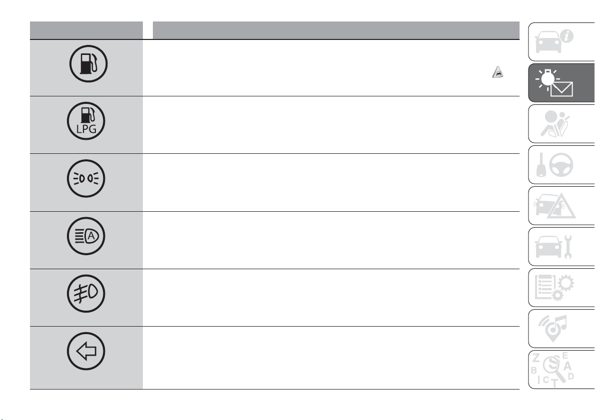
Warning light What it means
yellow
FUEL RESERVE / LIMITED RANGE
This warning light or icon on the display turns on when about 5 to 7 litres of fuel are left in the tank.
25)
yellow
LPG FUEL RESERVE
The warning light switches on when the residual quantity of LPG drops below 1/5 of the tank capacity.
green
SIDE LIGHTS AND DIPPED BEAM HEADLIGHTS
The warning light switches on when the side lights or dipped headlights are turned on.
This function allows the headlights to remain on for 30, 60 or 90 seconds after the ignition device was
placed in STOP position ("Follow me" function).
green
AUTOMATIC MAIN BEAM HEADLIGHTS
This warning light comes on when the automatic main beam headlights are activated.
green
FOG LIGHTS
The warning light comes on when the front fog lights are turned on.
green
LEFT DIRECTION INDICATOR
The warning light switches on when the direction indicator control stalk is moved downwards or, together
with the right direction indicator, when the hazard warning light button is pressed.
59
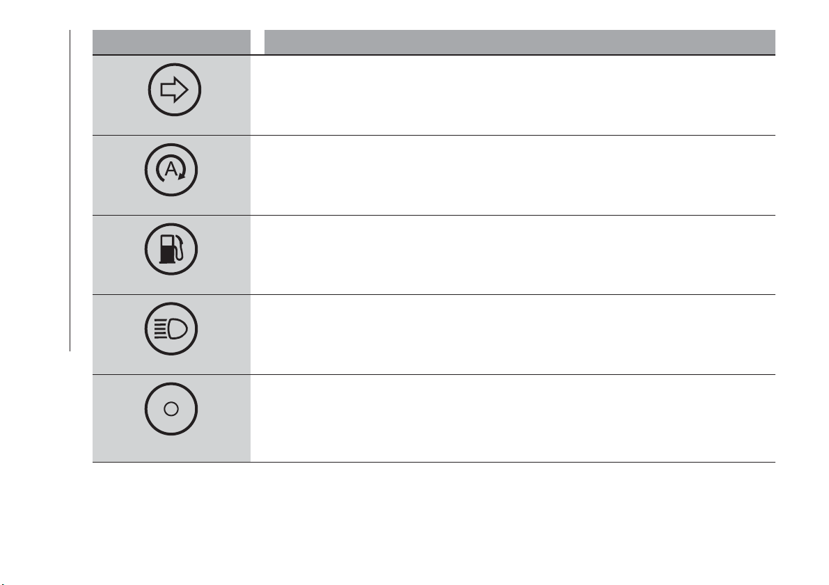
Warning light What it means
green
RIGHT DIRECTION INDICATOR
The warning light switches on when the direction indicator control stalk is moved upwards or, together with
the left direction indicator, when the hazard warning light button is pressed.
green
START&STOP SYSTEM ACTIVATION
The symbol turns on to indicate that the engine has been switched off by the Start&Stop system.
Activation: the symbol turns on when the system is activated; in this case the LED on the button is off.
Deactivation: a dedicated message appears on the display when the Start&Stop system is deactivated; in
this case the LED on the button is on.
green
RUNNING ON PETROL
The warning light turns on when running on petrol.
blue
MAIN BEAM HEADLIGHTS
The warning light switches on when the main beam headlights are turned on.
white
BRIGHTNESS SENSOR
This sensor measures the light in the passenger compartment and autonomously adjusts the instrument
panel brightness.
60
KNOWING THE INSTRUMENT PANEL
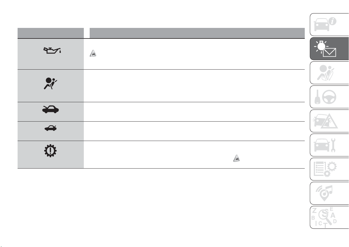
SYMBOLS ON THE DISPLAY
Symbol What it means
red
LOW ENGINE OIL PRESSURE
The symbol switches on, together with a message on the display, if there is insufficient engine oil pressure.
26)
IMPORTANT Do not use the car until the failure has been solved. The switching on of the symbol does not
show the quantity of oil in the engine: the oil level must be checked manually.
red
AIR BAG FAILURE
If the symbol switches on constantly, this indicates a failure in the airbag system. Contact a Fiat Dealership
as soon as possible.
red
BONNET NOT PROPERLY SHUT
The symbol switches on when the engine bonnet is not properly shut. Close the bonnet properly.
red
TAILGATE NOT PROPERLY SHUT
The symbol switches on when the tailgate is not properly shut. Close the tailgate correctly.
red
AT9 AUTOMATIC TRANSMISSION FAILURE / DUAL CLUTCH AUTOMATIC TRANSMISSION FAILURE
The symbol turns on to indicate that there is a failure in the automatic transmission or in the dual clutch
automatic transmission. Contact a Fiat Dealership as soon as possible.
27)
61
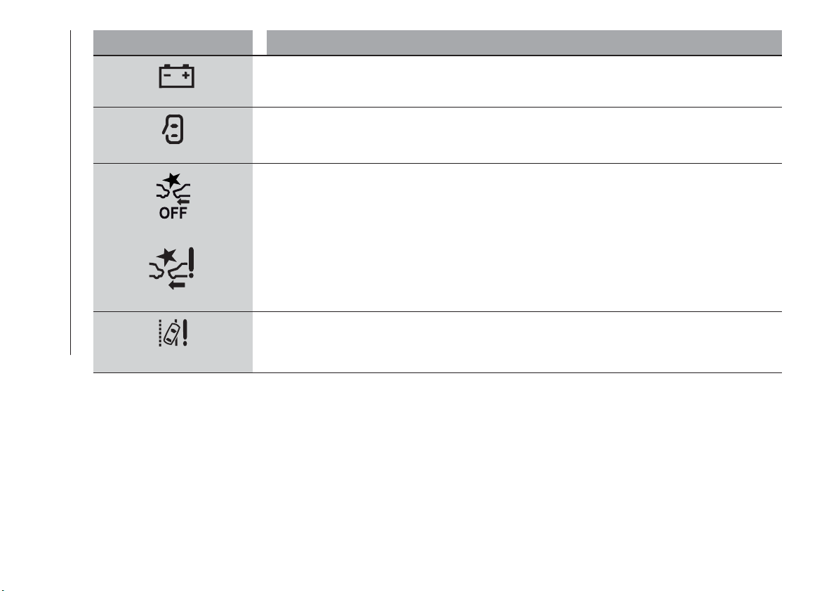
Symbol What it means
red
ALTERNATOR FAILURE
The switching on of the symbol with engine on corresponds to an alternator failure. Contact a Fiat
Dealership as soon as possible.
red
DOOR OPEN
The symbol switches on when one or more doors are not completely shut. An acoustic signal is activated
with the doors open and the car moving. Close the doors properly.
yellow
yellow
FULL BRAKE CONTROL SYSTEM FAILURE
The symbols switch on (with the displayed message) in the case of failure of the Full Brake Control system.
Contact a Fiat Dealership as soon as possible.
yellow
LANE ASSIST SYSTEM FAILURE
The symbol comes on in the case of permanent Lane Assist system failure. Contact a Fiat Dealership as
soon as possible.
62
KNOWING THE INSTRUMENT PANEL
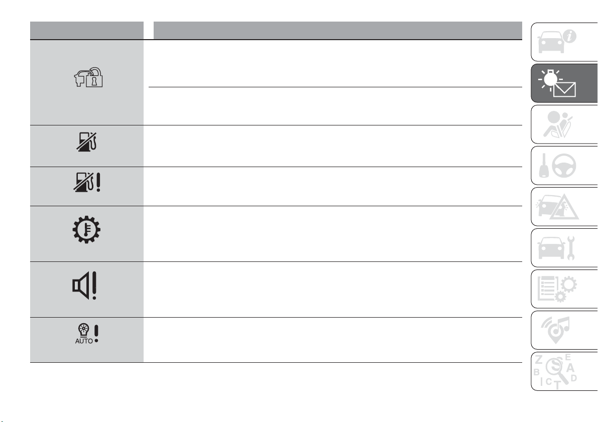
Symbol What it means
yellow
FIAT CODE SYSTEM FAILURE/BREAK-IN ATTEMPT
Fiat CODE system failure
The symbol switches on to indicate a failure of the Fiat CODE system. Contact a Fiat Dealership as soon as
possible.
Break-in attempt
The symbol switches on when the ignition device is moved to MAR position, to indicate a possible break-in
attempt detected by the alarm system.
yellow
FUEL CUT-OFF SYSTEM OPERATION
The symbol switches on in the event of fuel cut-off system intervention.
For reactivating the fuel cut-off system, refer to the description in the "Fuel cut-off system" section in the "In
an emergency" chapter. If it is still not possible to restore the fuel supply, contact a Fiat Dealership.
yellow
FUEL CUT-OFF SYSTEM FAILURE
The symbol switches on in the event of fuel cut-off system failure. Contact a Fiat Dealership as soon as
possible.
yellow
EXCESSIVE AT9 AUTOMATIC TRANSMISSION OIL TEMPERATURE / EXCESSIVE DUAL CLUTCH
AUTOMATIC TRANSMISSION OIL TEMPERATURE
The symbol switches on in the case of transmission overheating, after a particularly demanding use. In this
case an engine performance limitation is carried out. With engine off or at idle speed, wait until the symbol
switches off.
yellow
AUDIO SYSTEM FAILURE
The symbol switches on to report a failure of the audio system. Contact a Fiat Dealership as soon as
possible.
yellow
DUSK SENSOR FAILURE
The symbol switches on along with a message on the display in the event of dusk sensor failure. Contact a
Fiat Dealership as soon as possible.
63
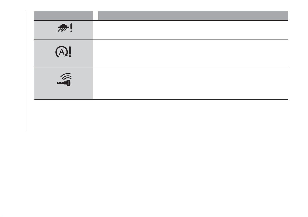
Symbol What it means
yellow
RAIN SENSOR FAILURE
The symbol switches on in the case of failure of the rain sensor. Contact a Fiat Dealership as soon as
possible.
yellow
START&STOP SYSTEM FAILURE
The symbol switches on to report a failure of the Start&Stop system. The display will show a dedicated
message. Contact a Fiat Dealership as soon as possible.
yellow
KEYLESS GO SYSTEM FAILURE
The symbol switches on in the event of Keyless Go system failure. Contact a Fiat Dealership as soon as
possible.
64
KNOWING THE INSTRUMENT PANEL
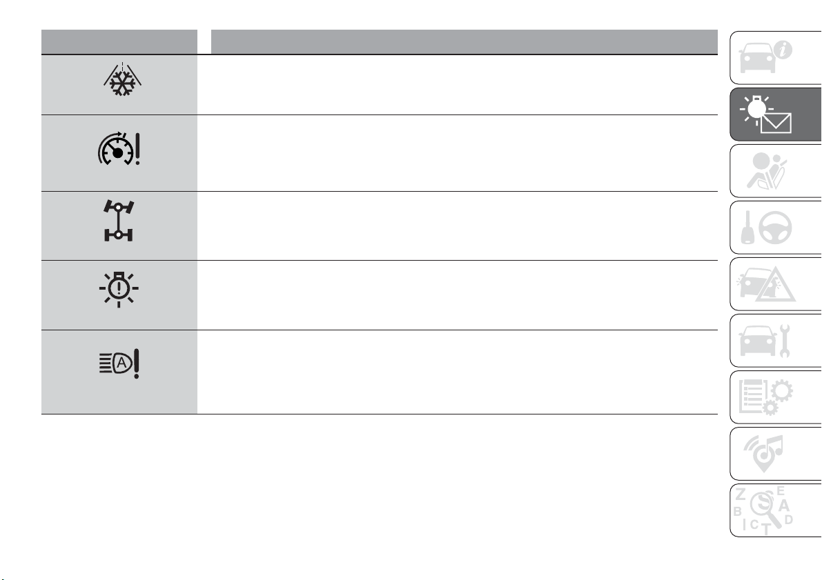
Symbol What it means
yellow
POSSIBLE ICE ON ROAD
The symbol turns on when the outside temperature falls to or below 3°C.
IMPORTANT In the event of outside temperature sensor failure, the digits that indicate the value are
replaced by dashes.
yellow
SPEED LIMITER FAILURE
The symbol switches on in the case of failure of the Speed Limiter device. Contact a Fiat Dealership as
soon as possible to have the failure eliminated.
yellow
4x4 ALL-WHEEL TRANSMISSION SYSTEM FAILURE
The symbol turns on to indicate that there is a failure in the four-wheel drive system. Contact a Fiat
Dealership as soon as possible.
yellow
EXTERIOR LIGHTS FAILURE
The symbol switches on to indicate a failure on the following lights: daytime running lights (DRLs); parking
lights; side lights; direction indicators; rear fog light; reversing light; number plate lights; stop lights.
The anomaly may be caused by a blown bulb, a blown protection fuse or an interruption of the electrical
connection.
yellow
AUTOMATIC MAIN BEAM HEADLIGHTS FAILURE
The symbol switches on to report a failure of the automatic main beam headlights. Contact a Fiat
Dealership as soon as possible.
65
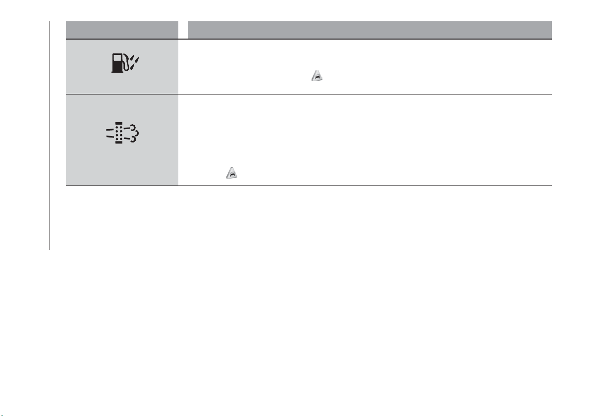
Symbol What it means
yellow
WATER IN DIESEL FILTER (Diesel versions)
The symbol switches on constantly while driving (along with a message in the display), to indicate the
presence of water in the diesel filter.
28)
yellow
DPF CLEANING (particulate trap) in progress (diesel versions with DPF only)
The symbol switches on constantly to indicate that the DPF system needs to eliminate the trapped
pollutants (particulate) through the regeneration process.
The symbol does not switch on during every DPF regeneration, but only when driving conditions require
that the driver is notified. To turn off the symbol, keep the vehicle in motion until the regeneration process is
over. On average, the process lasts 15 minutes. Optimal conditions for completing the process are
achieved by travelling at 60 km/h with engine speed above 2000 rpm.
When this symbol switches on, it does not indicate a defect of the car and thus it should not be taken to a
workshop.
29)
66
KNOWING THE INSTRUMENT PANEL
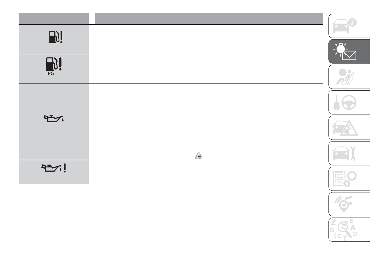
Symbol What it means
yellow
FUEL LEVEL SENSOR FAILURE
The symbol switches on in the event of fuel level sensor failure. Contact a Fiat Dealership.
yellow
LPG FUEL SUPPLY SYSTEM FAILURE
The symbol on the display turns on in the event of an LPG fuel system failure. In this case, all the bars on
the digital indicator will be off.
In the event of a failure, contact a Fiat Dealership.
yellow
ENGINE OIL DETERIORATED
(where provided)
Diesel versions: the symbol turns on and is displayed for 3 minute cycles and intervals of 5 seconds until
the oil is changed.
The symbol is displayed until the problem is solved.
Petrol versions: the symbol switches on and then is not displayed when the display cycle is completed.
IMPORTANT After the first indication, each time the engine is started the symbol will continue to switch on
as described above until the oil is changed.
If the symbol flashes, this does not mean that there is a fault on the vehicle, rather it simply reports that it is
now necessary to change the oil as a result of regular use of the vehicle.
The deterioration of engine oil is accelerated by using the car for short drives, preventing the engine from
reaching operating temperature.
Contact a Fiat Dealership as soon as possible.
30) 31)
yellow
ENGINE OIL PRESSURE SENSOR FAILURE
The symbol switches on constantly together with the message in the display in the case of engine oil
pressure sensor failure.
67
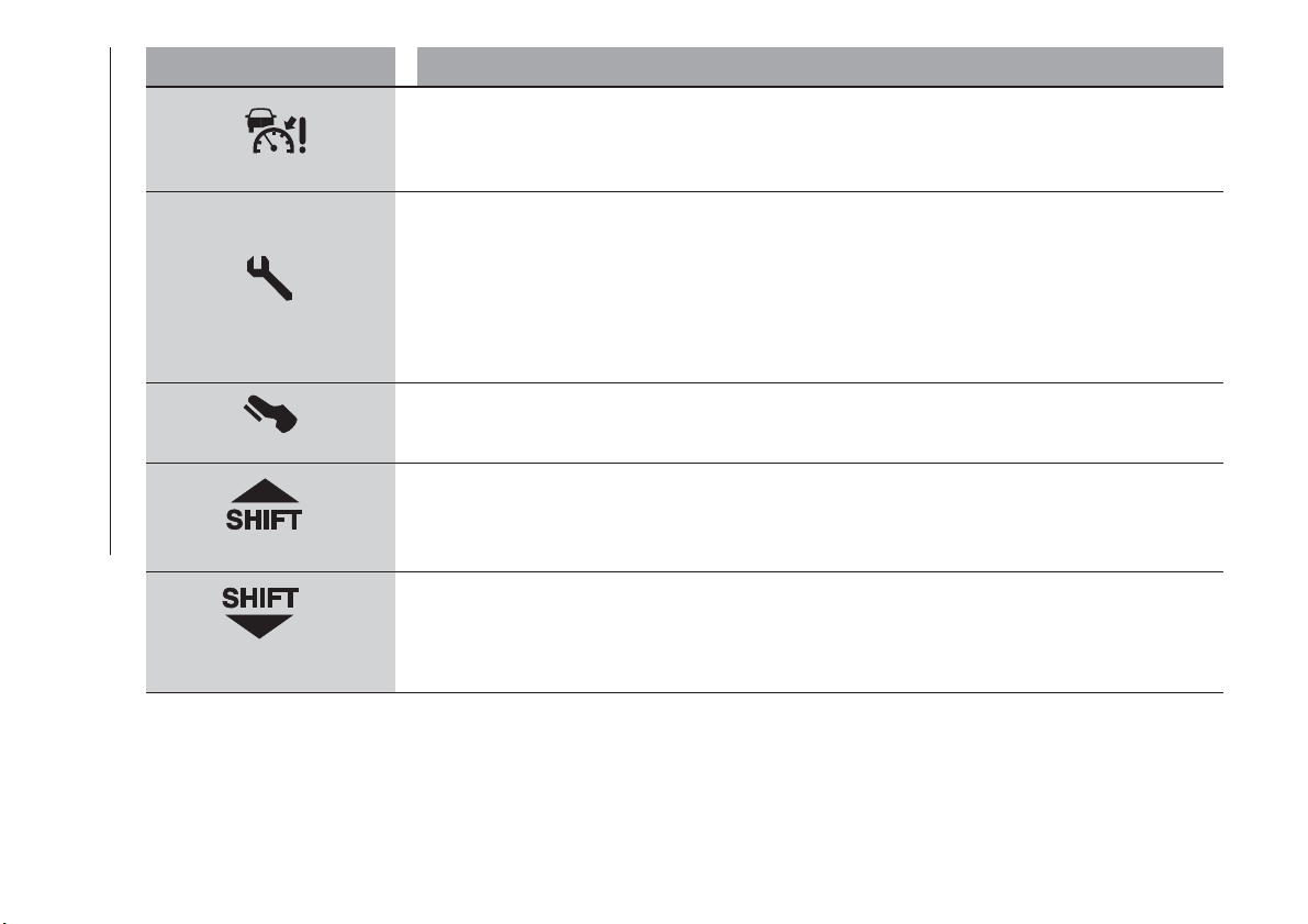
Symbol What it means
yellow
ADAPTIVE CRUISE CONTROL (ACC) FAILURE
(where provided)
The symbol turns on (together with a message on the display) to indicate an Adaptive Cruise Control (ACC)
system failure. Contact a Fiat Dealership.
yellow
SCHEDULED SERVICING (SERVICE)
The “Service Schedule” includes car maintenance at fixed intervals (refer to the "Maintenance and care"
chapter). When the next scheduled service is approaching, the symbol will be displayed, followed by the
number of kilometres/miles or days (where provided) left, when the ignition device is turned to MAR.
This is displayed automatically, with ignition device at MAR, 2000 km before servicing or, where provided,
30 days before servicing. It is also displayed each time the ignition device is turned to MAR. The display will
be in km or miles depending on the unit of measurement set.
Go to a Fiat Dealership, where the "Scheduled Servicing Plan" operations will be performed and the
message will be reset.
white
This symbol turns on to indicate that the clutch pedal must be pressed to enable starting.
white
This symbol appears to suggest engaging a higher gear (upshifting).
white
The symbol appears to suggest engaging a lower gear (downshifting).
68
KNOWING THE INSTRUMENT PANEL
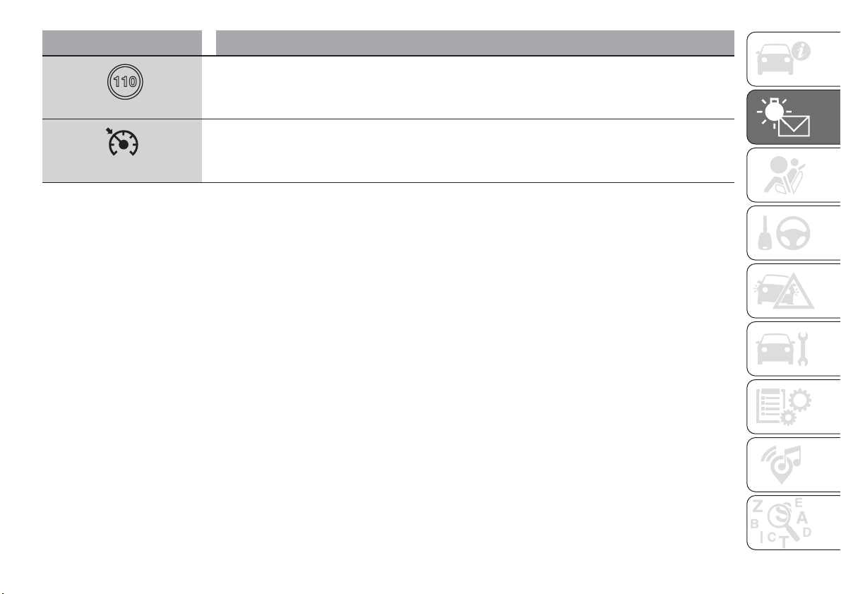
Symbol What it means
white
SPEED LIMIT EXCEEDED
The (white) symbol switches on when the speed limit (e.g. 110 km/h) set through the menu of the display is
exceeded (the inner value updates according to the set speed).
white
ELECTRONIC CRUISE CONTROL
The symbol switches on if the electronic Cruise Control is activated.
69
Messages on the display
Message on display
BLIND SPOT ASSIST
BLIND
SPOT ASSIST SYSTEM
Sensor locking: in case of failure of the Blind Spot Assist system sensor, a
message will appear on the display. In this case, the LEDs on the door mirrors are
switched on continuously. Free the bumper of any obstacles or clean it.
System not available: in case the Blind Spot Assist system is not available, a
message will appear on the display. In this case, the LEDs on the door mirrors are
switched on continuously. The failed operation of the system might be due to the
insufficient voltage from the battery or other failures on the electrical system.
Contact a Fiat Dealership as soon as possible to have the electrical system
checked.
Blind Spot Assist system failure: in case of a failure of the Blind Spot Assist
system, a message will appear on the display. In this case, the LEDs on the door
mirrors are switched off. An acoustic signal is also emitted. Contact a Fiat
Dealership as soon as possible.
DYNAMIC STEERING TORQUE
DST SYSTEM (Dynamic Steering Torque)
A dedicated message is displayed in the case of a DST system failure. Contact a
Fiat Dealership as soon as possible.
PARK ASSIST
ACTIVE PARK ASSIST (where provided)
Temporary parking sensors failure: a dedicated message is displayed in case
of a temporary failure of the parking sensors. If the problem is still present after
cleaning the parking sensor area, contact a Fiat Dealership.
Permanent parking sensors failure: a dedicated message is displayed in case
of a permanent failure of the parking sensors. The failed operation of the system
might be due to the insufficient voltage from the battery or other failures of the
electrical system. Contact a Fiat Dealership as soon as possible.
LANE ASSIST
LANE ASSIST SYSTEM
Camera obstructed: a dedicated message is shown on the display in the case
of dirt on the windscreen, which may adversely affect correct operation of the
camera. Clean the windscreen using a soft clean cloth, taking care not to scratch
it. Should the failure persist, contact a Fiat Dealership as soon as possible.
70
KNOWING THE INSTRUMENT PANEL
Message on display
START&STOP
ST
ART&STOP SYSTEM ACTIVATION/DEACTIVATION
Activation: the system activation is signalled by a message on the display. In this
case, the LED on the button is off.
Deactivation: a message will appear on the display when the system is off. In
this case, the LED on the button is on.
71
WARNING
31) If, when the ignition device is turned to MAR, the warning light does not switch on or stays on whilst driving, a failure may have
occurred in the restraint systems. In this case the airbags or pretensioners may not be deployed in an impact or, in a lower number of cases,
they may be deployed accidentally. Before continuing, contact a Fiat Dealership immediately to have the system checked.
32) The fault of the
warning light is signalled by the switching on of the icon on the instrument panel. In this case, the warning light may
not indicate any faults with the restraint systems. Before continuing, contact a Fiat Dealership immediately to have the system checked.
33) If a failure is present with sharp braking, the rear wheels may lock and the vehicle may swerve.
IMPORTANT
24) If, turning the ignition device to MAR, the warning light does not turn on or if it turns on steadily or flashing when travelling (on some
versions together with the message on the display), contact a Fiat Dealership as soon as possible.
25) If the warning light (or the icon on the display) flashes whilst driving, contact a Fiat Dealership.
26) If the symbol switches on when driving, stop the engine immediately and contact a Fiat Dealership.
27) Driving the vehicle with this symbol on may severely damage the gearbox, with resulting breakage. The oil may also overheat: contact with
hot engine or with exhaust components at high temperature could cause fires.
28) The presence of water in the fuel system circuit may cause severe damage to the injection system and irregular engine operation. If the
symbol is displayed contact a Fiat Dealership as soon as possible to bleed the system. If the above indications come on immediately after
refuelling, water has probably been poured into the tank: switch the engine off immediately and contact a Fiat Dealership.
29) Vehicle travel speed should always be adapted to the traffic and weather conditions, and must always comply with traffic regulations. The
engine can be stopped even if the DPF warning light is on: however, repeated interruptions of the regeneration process could cause
premature deterioration of the engine oil. For this reason it is always advisable to wait for the symbol to go off before turning off the engine,
following the instructions above. Do not complete the DPF regeneration process when the vehicle is stopped.
30) If the
warning light comes on, the exhausted engine oil should be changed as soon as possible, never drive more than 500 km from
the first switching-on of this warning light. Failure to observe the above may result in severe damage to the engine and invalidate the warranty.
Remember that when this warning light comes on, it does not mean that the level of engine oil is low, so if it flashes you do not need to top up
the engine oil.
31) If the symbol flashes when driving, contact a Fiat Dealership.
72
KNOWING THE INSTRUMENT PANEL
SAFETY
The chapter that you are about to read
is very important: it describes the safety
systems with which the vehicle is
equipped and provides instructions on
how to use them correctly.
ACTIVE SAFETY SYSTEMS ......74
DRIVING ASSISTANCE SYSTEMS . .78
OCCUPANT PROTECTION
SYSTEMS .................87
SEATBELTS................87
SBR (Seat Belt Reminder)
SYSTEM ..................89
PRE-TENSIONERS ............91
CHILD RESTRAINT SYSTEMS ....93
SUPPLEMENTARY RESTRAINT
SYSTEM (SRS) - AIRBAG .......106
73
ACTIVE SAFETY
SYSTEMS
The vehicle has the following active
safety systems:
ABS (Anti-lock Braking System);
DTC (Drag Torque Control);
ESC (Electronic Stability Control);
TC (Traction Control);
PBA (Panic Brake Assist);
HHC (Hill Hold Control);
DST (Dynamic Steering Torque);
ERM (Electronic Rollover Mitigation);
TSC (Trailer Sway Control).
For the operation of the systems, see
the following description.
ABS (Anti-lock Braking
System)
This system, which is an integral part of
the braking system, prevents one or
more wheels from locking and slipping
in all road surface conditions,
irrespective of the intensity of the
braking action, ensuring that the vehicle
can be controlled even during
emergency braking and optimising
stopping distances.
The system intervenes during braking
when the wheels are about to lock,
typically in emergency braking or
low-grip conditions, when locking may
be more frequent.
The system also improves control and
stability of the vehicle when braking on
a surface where the grip of the left and
right wheels varies, or on corners.
The Electronic Braking Force
Distribution (EBD) system completes
the system allowing the brake force to
be distributed between the front and
rear wheels.
System intervention
The driver can feel that the ABS system
has come into action because the
brake pedal pulsates slightly and the
system gets noisier: this is entirely
normal with the system operating.
34) 35) 36) 37) 38) 39) 40)
DTC (Drag Torque
Control) SYSTEM
The DTC (Drag Torque Control) system
prevents the drive wheels from possibly
locking, which could happen, for
example, if the accelerator pedal is
released suddenly or in the case of a
sudden downshifting in conditions of
poor grip. In this conditions, the engine
braking effect could cause the drive
wheels to slip, resulting in a loss of car
stability. In these situations, the DTC
system intervenes, restoring torque to
the engine in order to conserve car
stability and increase car safety.
ESC (Electronic Stability
Control) SYSTEM
The ESC system improves the
directional control and stability of the
vehicle in various driving conditions.
The ESC system corrects the vehicle’s
understeer and oversteer, distributing
the brake force on the wheels
appropriately. The torque supplied by
the engine can also be reduced in order
to maintain control of the vehicle.
The ESC system uses sensors installed
on the vehicle to determine the
trajectory that the driver intends to
follow and compares it with the
vehicle’s effective trajectory. When the
real trajectory deviates from the desired
trajectory, the ESC system intervenes to
counter the vehicle’s understeer or
oversteer.
Oversteer: occurs when the vehicle is
turning more than it should according
to the angle of the steering wheel.
Understeer: occurs when the vehicle
is turning less than it should according
to the angle of the steering wheel.
74
SAFETY
System intervention
The intervention of the system is
indicated by the flashing of the
warning light on the instrument
panel, to inform the driver that the
vehicle is in critical stability and grip
conditions.
41) 42) 43) 44) 45)
TC (Traction Control)
SYSTEM
The system automatically operates in
the event of slipping, loss of grip on wet
roads (aquaplaning) and acceleration on
slippery, snowy or icy roads, etc. on
one or more drive wheels. Depending
on the slipping conditions, two different
control systems are activated:
if the slipping involves both drive
wheels, the system intervenes, reducing
the power transmitted by the engine;
if the slipping only involves one of the
drive wheels, the BLD (Brake Limited
Differential) function is activated,
automatically braking the wheel which
is slipping (the behaviour of a
self-locking differential is simulated).
This will increase the engine torque
transferred to the wheel which isn't
slipping. This function remains active
even if the "Systems partially disabled"
and "Systems disabled" modes are
selected (see description in the
following pages).
System intervention
The intervention of the system is
indicated by the flashing of the
warning light on the instrument
panel, to inform the driver that the
vehicle is in critical stability and grip
conditions.
46) 47) 48) 49) 50)
PBA (Panic Brake
Assist) SYSTEM
The PBA system is designed to improve
the vehicle’s braking capacity during
emergency braking.
The system detects emergency braking
by monitoring the speed and force with
which the brake pedal is pressed, and
consequently applies the optimal brake
pressure. This can reduce the braking
distance: the PBA system therefore
completes the ABS.
Maximum assistance from the PBA
system is obtained by pressing the
brake pedal very quickly. In addition, the
brake pedal should be pressed
continuously during braking, avoiding
intermittent presses, to get the most
out of the system. Do not reduce
pressure on the brake pedal until
braking is not necessary anymore.
The PBA system is deactivated when
the brake pedal is released.
51) 52) 53)
HHC (Hill Hold Control)
SYSTEM
This is an integral part of the ESC
system and facilitates starting on
slopes, activating automatically in the
following cases:
uphill: vehicle stationary on a road
with a gradient higher than 5%, engine
running, brake pressed and
transmission in neutral or gear other
than reverse engaged;
downhill: vehicle stationary on a road
with a gradient higher than 5%, engine
running, brake pressed and reverse
gear engaged.
When setting off, the ESC system
control unit maintains the braking
pressure on the wheels until the engine
torque necessary for starting is
reached, or in any case for a maximum
of 2 seconds, allowing your right foot to
be moved easily from the brake pedal
to the accelerator.
When two seconds have elapsed,
without starting, the system is
automatically deactivated, gradually
releasing the braking pressure. During
this release stage it is possible to hear a
typical mechanical brake release noise,
indicating the imminent movement of
the vehicle.
54) 55)
75
DST SYSTEM (Dynamic
Steering Torque)
The DST function uses the integration
of the ESC system with the electric
power steering to increase the safety
level of the whole vehicle.
In critical situations (braking on surfaces
with different grip conditions), through
the DST function the ESC system
controls the steering to implement an
additional torque contribution on the
steering wheel, to suggest the most
correct manoeuvre to the driver.
The coordinated action of the brakes
and steering increases the sensation of
safety and control of the vehicle.
56)
ERM (Electronic Rollover
Mitigation) SYSTEM
The system monitors the tendency of
the wheels to rise from the ground if the
driver performs extreme manoeuvres
like quick steering to avoid an obstacle,
especially in poor road conditions.
If these conditions occur, the system
intervenes on the brakes and engine
power to reduce the possibility that the
wheels are raised from the ground. It is
not possible to avoid tendency to roll
over if the phenomenon is due to
reasons such as driving on high side
gradients, collision with objects or other
vehicles.
57)
TSC (Trailer Sway
Control) SYSTEM
The system employs a series of sensors
located on the vehicle to identify
excessive swerving of the trailer and
take the necessary precautions to
eliminate it.
To counteract the effect of trailer sway,
the system can reduce the engine
power and intervene on the wheels
involved. The TSC system activates
automatically once excessive sway of
the trailer is detected.
System intervention
When the system is active, the
warning light flashes on the
instrument panel, the engine power is
reduced and braking can be felt on the
individual wheels, following the attempt
to eliminate the swerving of the trailer.
58) 59)
WARNING
34) When the ABS intervenes and you feel
the brake pedal pulsating, do not reduce
the pressure, but hold it down firmly and
confidently; in doing so you will brake in the
shortest distance possible, depending on
the current road conditions.
35) To obtain the maximum efficiency of
the braking system, a bedding-in period of
about 500 km is needed: during this period
it is better to avoid sharp, repeated and
prolonged braking.
36) If the ABS intervenes, this indicates
that the grip of the tyres on the road is
nearing its limit: you must slow down to a
speed compatible with the available grip.
37) The ABS cannot overrule the natural
laws of physics, and cannot increase the
grip available according to the condition of
the road.
38) The ABS cannot prevent accidents,
including those due to excessive speed on
corners, driving on low-grip surfaces or
aquaplaning.
76
SAFETY
39) The capability of the ABS must never
be tested irresponsibly and dangerously, in
such a way as to compromise personal
safety and the safety of others.
40) For the correct operation of the ABS,
the tyres must of necessity be the same
make and type on all wheels, in perfect
condition and, above all, of the prescribed
type and dimensions.
41) The ESC system cannot alter the
natural laws of physics, and cannot
increase grip, which depends on the
condition of the road.
42) The ESC system cannot prevent
accidents, including those due to excessive
speed on corners, driving on low-grip
surfaces or aquaplaning.
43) The capability of the ESC system must
never be tested irresponsibly and
dangerously, in such a way as to
compromise personal safety and the safety
of others.
44) For the correct operation of the ESC
system, the tyres must necessarily be of
the same make and type on all wheels, in
perfect condition and, above all, of the
prescribed type and size.
45) ESC performance features must not
induce the driver to take unnecessary or
unwarranted risks. Your driving style must
always be suited to the road conditions,
visibility and traffic. The driver is, in any
case, responsible for safe driving.
46) For the correct operation of the TC
system, the tyres must of necessity be the
same make and type on all wheels, in
perfect condition and, above all, of the
prescribed type and dimensions.
47) TC performance features must not
induce the driver to take unnecessary or
unwarranted risks. Your driving style must
always be suited to the road conditions,
visibility and traffic. The driver is, in any
case, responsible for safe driving.
48) The TC system cannot overrule the
natural laws of physics, and cannot
increase the grip available according to the
condition of the road.
49) The TC system cannot prevent
accidents, including those due to excessive
speed on corners, driving on low-grip
surfaces or aquaplaning.
50) The capability of the TC must never be
tested irresponsibly and dangerously, in
such a way as to compromise personal
safety and the safety of others.
51) The PBA system cannot overrule the
natural laws of physics, and cannot
increase the grip available according to the
condition of the road.
52) The PBA system cannot prevent
accidents, including those due to excessive
speed on corners, driving on low-grip
surfaces or aquaplaning.
53) The capability of the PBA system must
never be tested irresponsibly and
dangerously, in such a way as to
compromise the safety of the driver, the
other occupants of the vehicle or any other
road user.
54) The Hill Hold Control system is not a
parking brake; therefore, never leave the
vehicle without having engaged the electric
parking brake, turned the engine off and
engaged first gear, so that it is parked in
safe conditions (for further information read
the "Parking" paragraph in the "Starting
and driving" chapter).
55) There may be situations on small
gradients (less than 8%), with vehicle
laden, in which the Hill Hold Control system
may not activate, causing a slight reversing
motion and increasing the risk of collision
with another vehicle or object. The driver is,
in any case, responsible for safe driving.
56) DST is an aid for driving and does not
relieve the driver of responsibility for driving
the vehicle.
57) The performance of a vehicle with ERM
must never be tested in imprudent or
dangerous ways, with the possibility of
putting the safety of the driver or other
people at risk.
58) When towing trailers, the utmost
caution at the wheel is recommended.
Never exceed the maximum permitted
loads (see the description in the "Weights"
paragraph in the "Technical Specifications"
chapter).
59) The TSC system cannot prevent
swerving for all trailers. If the system
activates during driving, reduce the speed,
stop the vehicle in a safe place and arrange
the load correctly to prevent the trailer from
swerving.
77
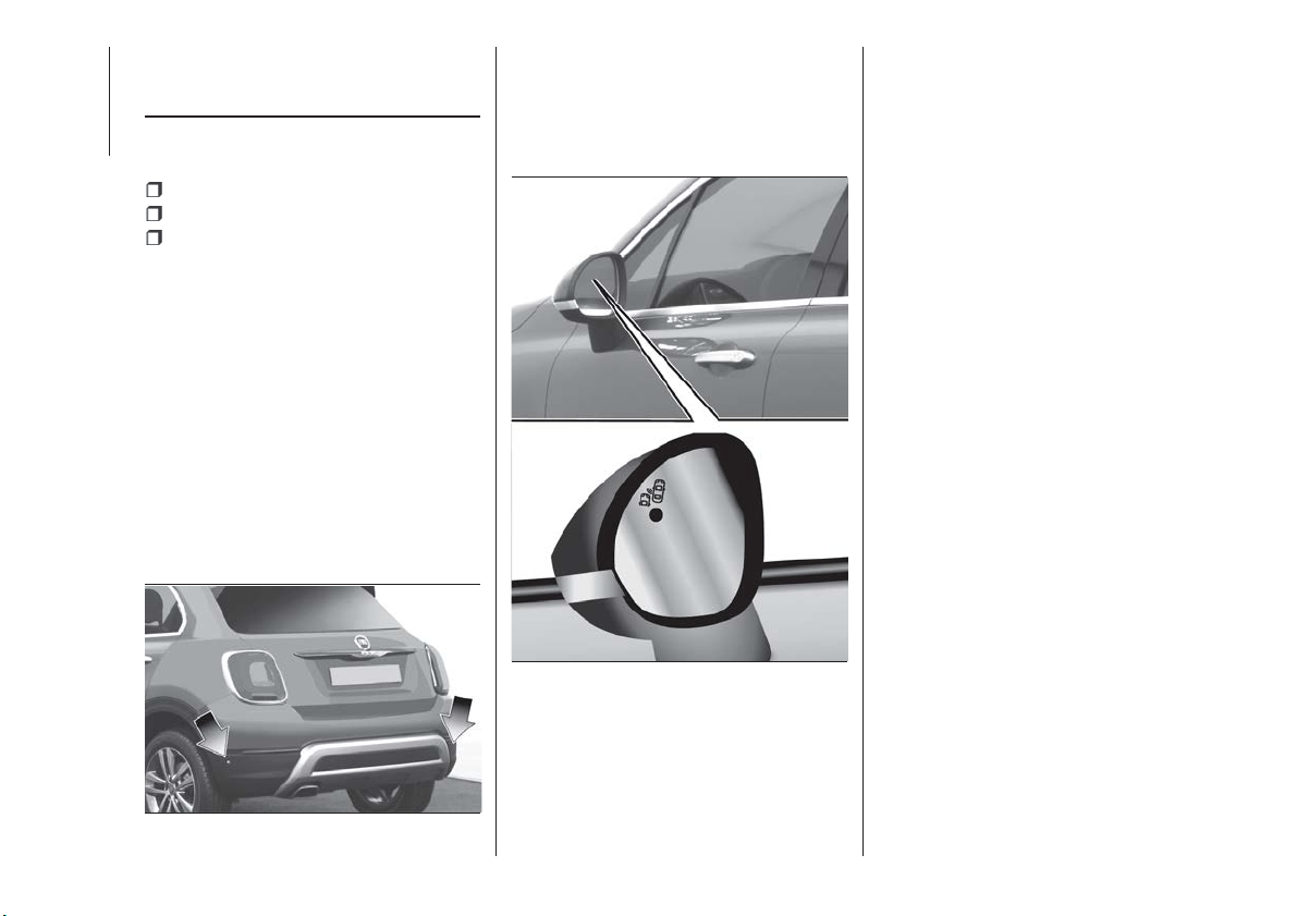
DRIVING
ASSISTANCE
SYSTEMS
The vehicle can feature the following
driving assistance systems:
BSA (Blind Spot Assist);
FBC (Full Brake Control);
iTPMS (indirect Tyre Pressure
Monitoring System).
For the operation of the systems, see
the following pages.
BSA (Blind-Spot Assist)
SYSTEM
The car can be equipped with the BSA
(Blind Spot Assist) system for blind spot
monitoring. The BSA system uses two
radar sensors, located in the rear
bumper (one for each side - see
fig. 60 ), to detect the presence of cars
(cars, trucks, motorbikes, etc.) in the
rear side blind spots of the car.
The system warns the driver about the
presence of cars in the detection area
by lighting up, on the relevant side, the
warning light located on the door mirror
fig. 61, along with an acoustic warning.
As soon as the ignition key is in MAR
position, or when the engine is started
(keyless version), the warning light turns
on to signal the driver that the system is
active.
Sensors
The sensors are activated when any
forward gear is engaged at a speed
higher than about 10 km/h, or when
reverse is engaged.
The sensors are temporarily deactivated
with car at a standstill and the gear
lever in position P (Park) (versions with
automatic transmission), or with car at a
standstill and electric parking brake
engaged (versions with manual
transmission).
The detection area of the system
covers about a lane on both sides of
the vehicle (around 3 metres).
This area starts from the door mirror
and extends for about 6 metres
towards the rear part of the car.
When the sensors are active the system
monitors the detection areas on both
sides of the car and warns the driver
about the possible presence of cars in
these areas.
While driving the system monitors the
detection area from three different input
points (side, rear and front) to check
whether a warning needs to be sent to
the driver. The system can detect the
presence of a vehicle in one of these
three areas.
60
F1B0093C
61
F1B0094C
78
SAFETY

IMPORTANT The system does not
signal the presence of fixed object (e.g.
safety barriers, poles, walls, etc.).
However, in some circumstances, the
system may activate in the presence of
these objects. This is normal and does
not indicate a system malfunction.
IMPORTANT The system does not
warn the driver about the presence of
vehicles coming from the opposite
direction, in the adjacent lanes.
60)
Important notes
If a trailer is connected to the car, to
avoid false indications this system must
be manually deactivated using the
relative menu.
For the system to operate correctly, the
rear bumper area where the radar
sensors are located must stay free from
snow, ice and dirt gathered from the
road surface.
Do not cover the rear bumper area
where the radar sensors are located
with any object (e.g. adhesives, bike
rack, etc.).
Rear-view
The system detects vehicles coming
from the rear part of your vehicle on
both sides and entering the rear
detection area with a difference in
speed of less than 50 km/h with
respect to your vehicle.
Overtaking vehicles
If another vehicle is overtaken slowly
(with a difference in speed of less than
about 25 km/h) and this stays in the
blind spot for about 1.5 seconds, the
warning light on the door mirror of the
corresponding side lights up.
If the speed delta between the two
vehicles is higher than about 25 km/h,
the warning light does not light up.
RCP (Rear Cross Path detection)
system
This system helps the driver during
reverse manoeuvres in the case of
reduced visibility.
The RCP system monitors the rear
detection areas on both sides of the
vehicle, to detect objects moving
towards the sides of the vehicle at a
minimum speed between about 1 km/h
and 3 km/h and objects moving at a
maximum speed of 35 km/h, as
generally happens in parking areas.
The system activation is signalled to the
driver by means of a visual and acoustic
warning.
IMPORTANT If the sensors are covered
by objects or vehicles, the system will
not warn the driver.
Operating mode
The system can be activated/
deactivated by operating on the display
Menu, or via the Uconnect™ system
(for further information see the
dedicated Supplement).
Blind Spot Assist "Visual" mode
When this mode is active, the BSA
system sends a visual warning to the
door mirror relating to the object
detected.
However, when operating in "RCP"
mode, the system produces acoustic
and visual warnings when if the
presence of an object is detected.
When an acoustic warning is sent,
theUconnect™ volume is lowered.
Blind Spot Assist "Visual &
acoustic" mode
When this mode has been activated,
the BSA system sends a visual warning
to the door mirror relating to the object
detected.
79
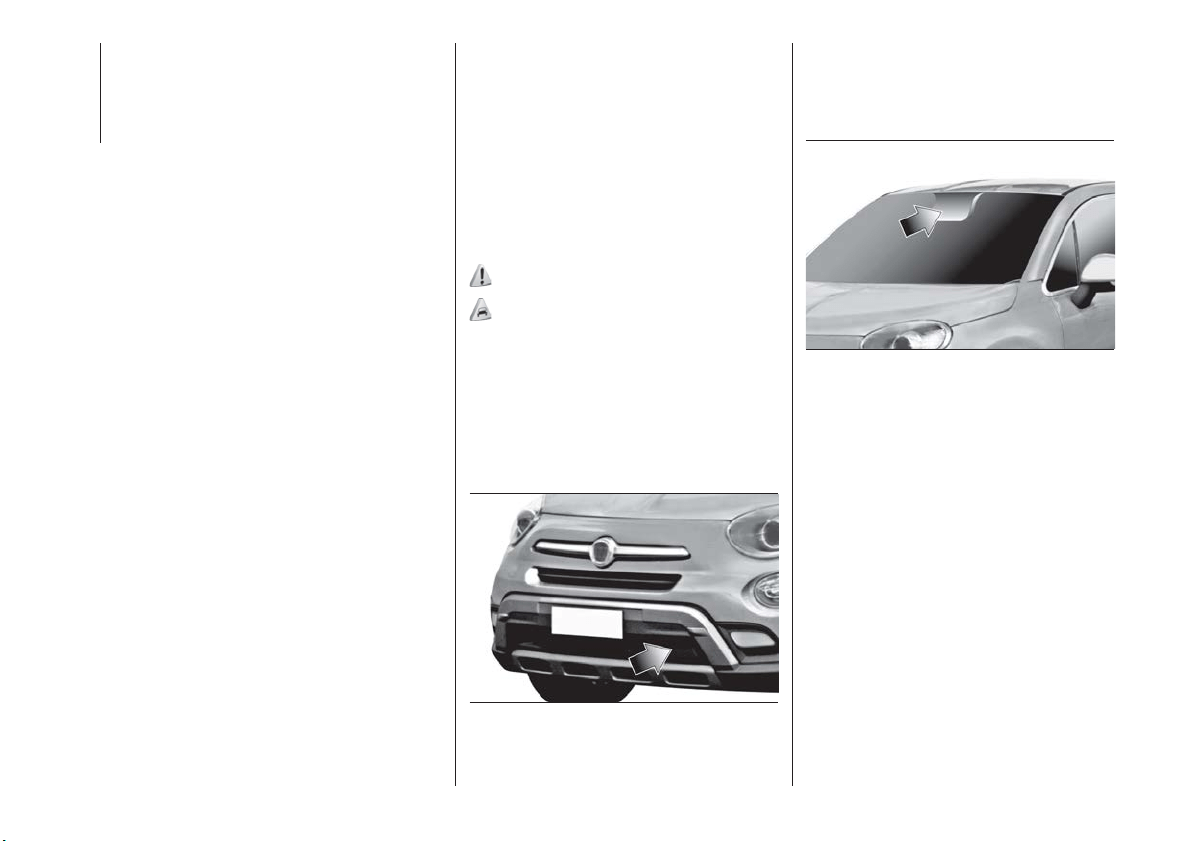
If the direction indicator on the side
where an obstacle has been detected is
activated, an acoustic warning is
emitted as well.
If a direction indicator is in operation
and an object is simultaneously
detected on the same side, both an
acoustic and a visual warning are
emitted. TheUconnect™ volume is
also lowered.
During "RCP" operating mode, the
system emits acoustic and visual
indications if the presence of an object
is detected. When an acoustic warning
is sent, theUconnect™ volume is also
lowered.
Deactivating the Blind Spot Assist
function
When the system is deactivated ("Blind
spot alert" mode at "OFF"), the BSA or
RCP systems will not emit either
acoustic nor visual warnings.
The BSA system will store the operating
mode running when the engine was
stopped. Each time the engine is
started, the operating mode stored
previously will be recalled and used.
IMPORTANT The system is an aid for
car driving, it DOES NOT warn the
driver about incoming cars outside of
the detection areas. The driver must
always maintain a sufficient level of
attention to the traffic and road
conditions and for controlling the
trajectory of the car.
FULL BRAKE CONTROL
SYSTEM
61) 62) 63) 64)
32) 33) 34) 35) 36) 37) 38) 39) 40)
The vehicle can be equipped with the
"Full Brake Control" system. This is a
driving assistance system which
comprises a radar located behind the
front bumper fig. 62 and a camera
located in the central part of the
windscreen fig. 63.
In the event of an imminent collision the
system intervenes by automatically
braking the vehicle to prevent the crash
or reduce its effects.
The system provides the driver with
acoustic and visual signals through
specific messages on the instrument
panel display.
The system may lightly brake to warn
the driver if a possible frontal accident is
detected (limited braking). Signals and
limited braking are intended to allow the
driver to react promptly, in order to
prevent or reduce the effects of a
potential accident.
In situations with the risk of collision, if
the system detects no intervention by
the driver, it provides automatic braking
to help slow the vehicle and mitigate
the potential frontal collision (automatic
braking).
62
F1B0095C
63
F1B0096C
80
SAFETY
If intervention by the driver on the brake
pedal is detected but not deemed
sufficient, the system may intervene in
order to improve the reaction of the
braking system, therefore reducing
vehicle speed further (additional
assistance in braking stage).
Versions equipped with Start&Stop
system: at the end of the automatic
braking, the Start&Stop system will
activate as described in paragraph
"Start&Stop system" of the "Starting
and driving" chapter.
Versions with manual gearbox:at
the end of the automatic braking the
engine may stall and turn off, unless the
driver presses the clutch pedal.
Versions with automatic
transmission / twin clutch
automatic transmission: at the end
of the braking, the latest stored gear is
engaged: the vehicle may therefore
restart after a few seconds from the
automatic stop.
IMPORTANT Both on versions
equipped with manual gearbox and on
those with automatic transmission, after
the vehicle is stopped the brake
callipers may be stuck for about
2 seconds for safety reasons. Make
sure you press the brake pedal if the
vehicle moves slightly forwards.
Activation/deactivation
The Full Brake Control system can be
deactivated (and then reactivated) via
the Uconnect™ system (see the
description in the dedicated
supplement).
The system can be deactivated even
with the ignition device at MAR.
IMPORTANT The system status can be
changed with vehicle at a standstill only.
The Full Brake Control system can be
set to three activation levels through the
Uconnect™ system:
System active: the system (if active),
in addition to the visual and acoustic
warnings, provides limited braking,
automatic braking and additional
assistance in braking stage, where the
driver does not brake sufficiently in the
event of a potential frontal impact;
System partially active: the system (if
active) does not provide limited braking,
but guarantees automatic braking or
additional assistance in braking stage,
where the driver does not brake at all or
not sufficiently in the event of a potential
frontal impact. The visual and acoustic
warnings are deactivated, and will not
be provided;
System deactivated: the system
does not provide visual and acoustic
warnings, limited braking, automatic
braking or additional assistance in
braking stage. The system will therefore
provide no indication of a possible
accident.
Activation/deactivation
If the Full Brake Control system has
been correctly activated with the
Uconnect™ system, this will be active
each time the engine is started.
Following a deactivation, the system will
not warn the driver about the possible
collision with the preceding vehicle,
regardless of the setting selected with
the Uconnect™ system.
The system deactivation status will not
be stored when the engine is switched
off: if the system is deactivated when
the engine is switched off, it will be
active when it is next started.
This function is not active at a speed
lower than 7 km/h or higher than
200 km/h.
The system is only active if:
it is correctly activated via the
Uconnect™ system;
the ignition device is at MAR;
the vehicle speed is between 7 and
200 km/h;
the front seat belts are fastened.
81

Changing the system sensitivity
The sensitivity of the system can be
changed through the Uconnect™
system menu, choosing from one of the
following three options: "Near", "Med"
or "Far". See the description in the
Uconnect™ supplement for how to
change the settings.
The pre-set option is "Med". With this
setting, the system warns the driver of a
possible collision with the vehicle in
front when that vehicle is at a standard
distance, between that of the other two
settings.
With the system sensitivity set to "Far",
the system will warn the driver of a
possible collision with the vehicle in
front when that vehicle is at a greater
distance, thus providing the possibility
of acting on the brakes more lightly and
gradually. This setting provides the
drivers with the maximum possible
reaction time to prevent a potential
accident.
With the option set to "Near", the
system will warn the driver of a possible
collision with the vehicle in front when
that vehicle is close. This setting offers
the driver a lower reaction time
compared to the "Med" and "Far"
settings, in the event of a potential
collision, but permits more dynamic
driving of the vehicle.
The system sensitivity setting is kept in
the memory when the engine is
switched off.
System limited operation signal
If the dedicated message is displayed,
a condition limiting the system
operation may have occurred. The
possible reasons of this limitation are
something blocking the camera view or
a fault.
If an obstruction is signalled, clean the
area of the windscreen indicated in
fig. 63 and check that the message has
disappeared.
Although the vehicle can still be driven
in normal conditions, the system may
be not completely available.
When the conditions limiting the system
functions end, this will go back to
normal and complete operation. Should
the fault persist, contact a Fiat
Dealership.
System failure signalling
If the system switches off and a
dedicated message is shown on the
display, it means that there is a fault on
the system.
In this case, it is still possible to drive
the vehicle, but you are advised to
contact a Fiat Dealership as soon as
possible.
Radar indication not available
If conditions are such that the radar
cannot detect obstacles correctly, the
system is deactivated and a dedicated
message will be shown on the display.
This generally occurs in the event of
poor visibility, such as when it is
snowing or raining heavily.
The system can also be temporarily
dimmed due to obstructions such as
mud, dirt or ice on the bumper. In such
cases, a dedicated message will be
shown on the display and the system
will be deactivated. This message can
sometimes appear in conditions of high
reflectivity (e.g. tunnels with reflective
tiles or ice or snow). When the
conditions limiting the system
functioning end, it will go back to a
normal and complete operation.
In certain particular cases, this
dedicated message could be displayed
when the radar is not detecting any
vehicle or object within its view range.
If atmospheric conditions are not the
real reason behind this message, check
if the sensor is dirty. It could be
necessary to clean or remove any
obstructions in the area illustrated in
fig. 62.
82
SAFETY
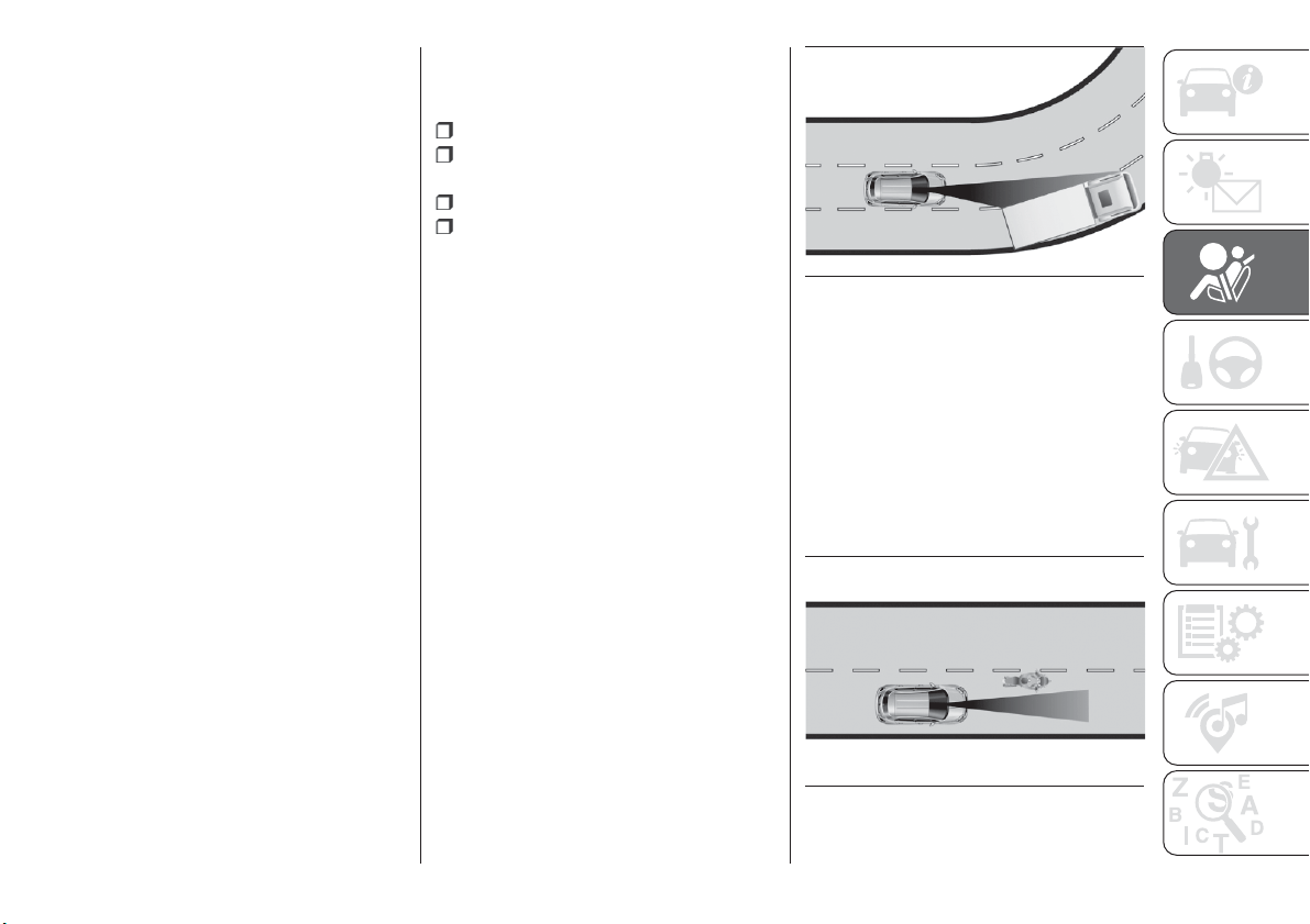
If the message appears often, even in
the absence of atmospheric conditions
such as snow, rain, mud or other
obstructions, contact a Fiat Dealership
for a sensor alignment check.
In the absence of visible obstructions,
cleaning the radar surface, by manually
removing the decorative cover trim,
could be required. Have this operation
performed at a Fiat Dealership.
IMPORTANT It is recommended that
you do not install devices, accessories
or aerodynamic attachments in front of
the sensor or darken it in any way, as
this can compromise the correct
functioning of the system.
Frontal collision alarm with active
braking
(where provided)
If this function is selected, the brakes
are operated to reduce the speed of the
vehicle in the event of potential frontal
impact
This function applies an additional
braking pressure if the braking pressure
applied by the driver does not suffice to
prevent potential frontal impact.
The function is active with speed above
7 km/h.
Driving in special conditions
In certain driving conditions, such as,
for example:
driving close to a bend;
vehicles with small dimensions
and/or not aligned in the driving lane;
lane change by other vehicles;
vehicles travelling at right angles to
the vehicle.
system intervention might be
unexpected or delayed. The driver must
therefore be very careful, keeping
control of the vehicle to drive in
complete safety.
IMPORTANT In particularly complex
traffic conditions, the driver can
deactivate the system through the
Uconnect™ system.
Driving close to a bend
When tackling a wide bend, the system
may detect the presence of a vehicle in
front you, but not running on the same
driving lane fig. 64. In cases such as
these, the system may intervene.
Vehicles with small dimensions
and/or not aligned in the driving
lane
The system cannot detect vehicles in
front of you but outside the range of the
radar sensor and may therefore not
react in the presence of small vehicles,
such as bicycles or motorcycles fig. 65.
64
F1B0097C
65
F1B0098C
83
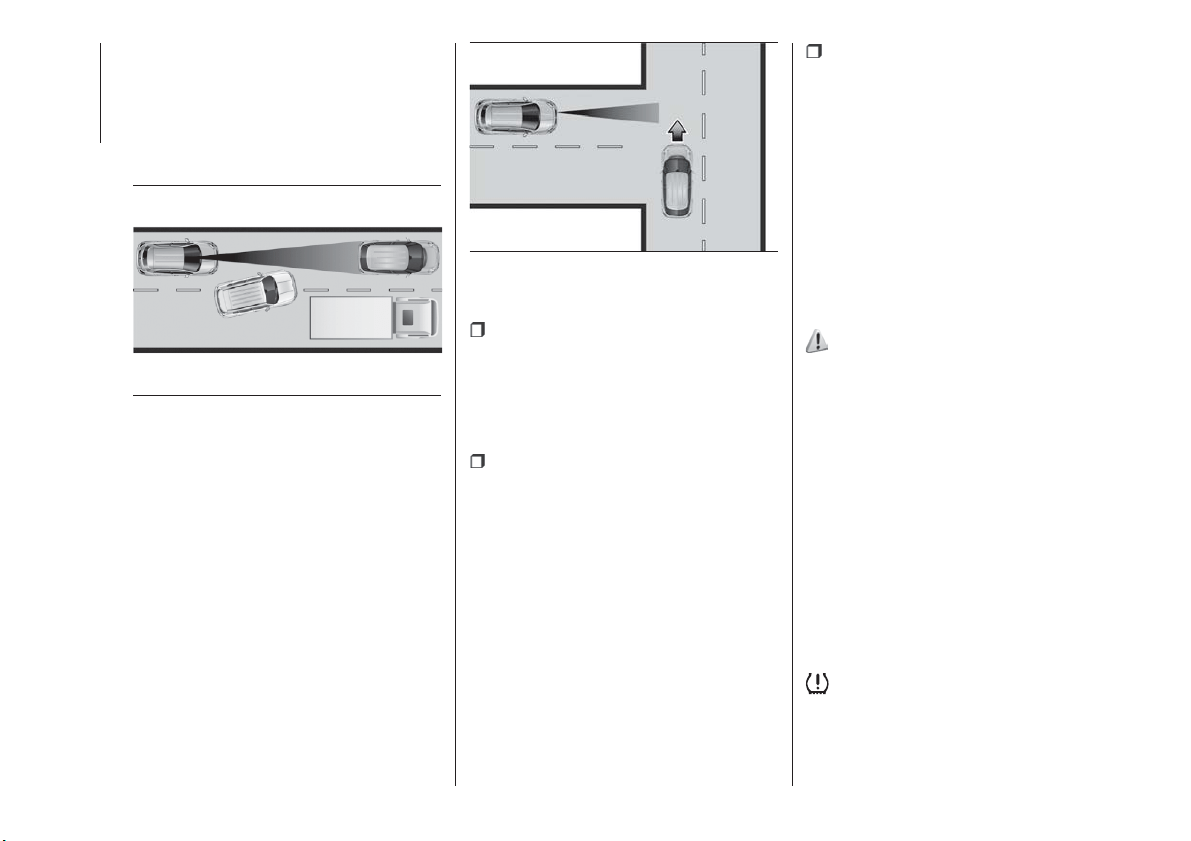
Lane change by other vehicles
Vehicles suddenly changing lane,
entering the driving lane of the vehicle
fig. 66 and inside the radar sensor
operating range, may cause system
activation.
Vehicles travelling at right angles to
the vehicle
The system may temporarily react to a
vehicle that is passing through the radar
sensor’s operating range at right angles
fig. 67.
Important
The system has not been designed
to prevent impacts and cannot detect
possible conditions leading to an
accident in advance. Failure to take into
account this warning may lead to
serious or fatal injuries.
The system may activate, assessing
the trajectory of the vehicle, due to the
presence of reflective metal objects
different from other vehicles, such as
safety barriers, road signs, barriers
before parking lots, tollgates, level
crossings, gates, railways, objects near
road constructions sites or higher than
the vehicle (e.g. a flyover). In the same
way, the system may intervene inside
multi-storey car parks or tunnels, or due
to a glare on the road surface. These
possible activations follow the normal
operating logic of the system and must
not be regarded as faults.
The system has been designed for
road use only. If the vehicle is driven
off-road, the system must be
deactivated, to avoid unnecessary
warnings. Automatic deactivation is
signalled by the dedicated warning
light/icon switching on in the instrument
panel (see the instructions in the
"Warning lights and messages"
paragraph, "Knowing the instrument
panel" chapter).
TPMS (Tyre Pressure
Monitoring System)
65) 66) 67) 68) 69) 70)
Description
The car can be equipped with the
iTPMS (indirect Tyre Pressure
Monitoring System) which monitors the
tyre inflation status thanks to wheel
speed sensors.
Correct tyre pressure
If no under-inflated tyres are detected,
the outline of the car will be shown on
the display.
Low tyre pressure
The system warns the driver if one or
more tyres are flat by switching on the
warning light on the instrument
panel and a warning message on the
display, along with an acoustic signal.
66
F1B0099C
67
F1B0100C
84
SAFETY
This warning is displayed also when
turning the engine off and on again until
the RESET procedure is carried out.
Reset procedure
The iTPMS needs an initial
"self-learning" phase (with length
depending on the driving style and road
conditions: optimal conditions being
driving on a straight road at 80 km/h for
at least 20 minutes) which starts when
the RESET procedure is carried out
manually.
The RESET procedure must be carried
out:
whenever the tyre pressure is
modified;
when even only one tyre is changed;
when tyres are rotated/inverted;
when the space-saver wheel is fitted.
Before carrying out the RESET
procedure, inflate the tyres to the rated
pressure values specified in the inflation
pressure table (see "Wheels" paragraph
in the "Technical specifications"
chapter).
If the RESET procedure is not carried
out, in all above cases, the
warning
light may give false indications on one
or more tyres.
To carry out the RESET procedure, with
the car stopped and the ignition device
at MAR, use the Main Menu as follows:
go to "Vehicle info" and then to
"Reset tyre pressure";
press the "OK" and hold down (more
than 2 seconds);
the display will show the procedure
progress (with a graphic bar) till the
RESET is completed.
At the end of the RESET procedure the
display will show the "Reset saved"
message, indicating that the
self-learning has been started and you
will hear a beep. If the self-learning
procedure of the iTPMS system has not
been carried out correctly, you will not
hear any acoustic warning.
Operating conditions
The system is active for speeds above
15 km/h.
In a few situations such as sporty
driving, particular conditions of the road
surface (e.g. icy, snowy, unsurfaced
roads) the signalling may be delayed or
partial in detecting the contemporary
deflation of more than one tyre.
Under special conditions (e.g. car
loaded asymmetrically on one side,
damaged or worn tyre, fitting the
space-saver spare wheel, use of the
"Fix&Go Automatic" tyre repair kit, fitting
snow chains, fitting different tyres on
the axles) the system may provide false
indications or be temporarily
deactivated.
If the system is temporarily deactivated
the
warning light flashes for about
75 seconds and then is continuously
on; at the same time, the display shows
a warning message and the symbols "–
–" will appear next to the shape of the
car next to each tyre.
This warning is displayed also after the
engine has been switched off and then
on again if the correct operating
conditions are not restored.
In the case of abnormal signals, it is
recommended to perform the RESET
procedure. If the indications appear
again after a successful RESET, check
that the tyres used on all four wheels
are the same and that the tyres are not
damaged. As soon as possible, refit the
standard tyre instead of the
space-saver spare, remove the snow
chains (if possible), check correct load
distribution and repeat the RESET
procedure by driving on a clean,
tarmacked road. If the indications
persist, contact a Fiat Dealership.
85
WARNING
60) The system is an aid for vehicle driving,
it DOES NOT warn the driver about
incoming vehicles outside of the detection
areas. The driver must always maintain a
sufficient level of attention to the traffic and
road conditions and for controlling the
trajectory of the vehicle.
61) The system is an aid for the driver, who
must always pay full attention while driving.
The responsibility always rests with the
driver, who must take into account the
traffic conditions in order to drive in
complete safety. The driver must always
maintain a safe distance from the vehicle in
front.
62) If the driver depresses the brake pedal
fully or carries out a fast steering during
system operation, the automatic braking
function may stop (e.g. to allow a possible
manoeuvre to avoid the obstacle).
63) The system intervenes on vehicles
travelling in the same lane. People, animals
and things (e.g. pushchairs) are not taken
into consideration.
64) If the car must be placed on a roller
bench for maintenance interventions or if it
is washed in an automatic roller washing
tunnel with an obstacle in the front part
(e.g. another car, a wall or another
obstacle), the system may detect its
presence and activate. In this case the
system must be deactivated through the
settings of the Uconnect™system.
65) If the iTPMS system signals a pressure
decrease on the tyres, it is recommended
to check the pressure on all four tyres.
66) The iTPMS does not relieve the driver
from the obligation to check the tyre
pressure every month; it is not even to be
considered a replacing system for
maintenance or a safety system.
67) Tyre pressure must be checked with
tyres cold. Should it become necessary for
whatever reason to check pressure with
warm tyres, do not reduce pressure even
though it is higher than the prescribed
value, but repeat the check when tyres are
cold
68) The iTPMS cannot indicate sudden tyre
pressure drops (e.g. if a tyre bursts). In this
case, stop the vehicle, braking with caution
and avoiding abrupt steering.
69) The system only warns that the tyre
pressure is low: it is not able to inflate
them.
70) Insufficient tyre inflation increases fuel
consumption, reduces the tread duration
and may affect the capacity to drive safely.
IMPORTANT
32) The system may have limited or absent
operation due to weather conditions such
as: heavy rain, hail, thick fog, heavy snow.
33) The section of the bumper before the
sensor must not be covered with
adhesives, auxiliary headlights or any other
object.
34) System intervention might be
unexpected or delayed when other vehicles
transport loads projecting from the side,
above or from the rear, with respect to the
normal size of the vehicle.
35) Operation can be adversely affected by
any structural change made to the vehicle,
such as a modification to the front
geometry, tyre change, or a heavier load
than the standard load of the vehicle.
36) Incorrect repairs made on the front part
of the vehicle (e.g. bumper, chassis) may
alter the position of the radar sensor, and
adversely affect its operation. Go to a Fiat
Dealership for any operation of this type.
37) Do not tamper with nor carry out any
intervention on the radar sensor or on the
camera on the windscreen. In the event of
a sensor failure, contact a Fiat Dealership.
38) When towing a trailer (with modules
installed after purchasing the vehicle), a
vehicle or during loading manoeuvres on a
vehicle transporter (or in vehicle for
transport), the system must be deactivated
via the Uconnect™system.
39) Do not wash with high-pressure jets in
the bumper lower area: in particular do not
operate on the system's electrical
connector.
40) Be careful in the case of repairs and
new paintings in the area around the
sensor (panel covering the sensor on the
left side of the bumper). In the event of a
frontal impact the sensor may automatically
deactivate and display a warning to indicate
that the sensor needs to be repaired. Even
without a malfunction warning, deactivate
the system operation if you think that the
position of the radar sensor has changed
(e.g. due to low-speed frontal impact as
during parking manoeuvres). In these
cases, go to a Fiat Dealership to have the
radar sensor realigned or replaced.
86
SAFETY
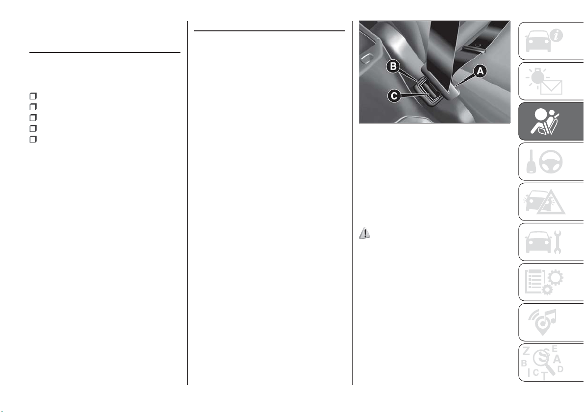
OCCUPANT
PROTECTION
SYSTEMS
The most important safety equipment
of the vehicle comprises the following
protection systems:
seat belts;
SBR (Seat Belt Reminder) system;
head restraints;
child restraint systems;
front airbags and side bags.
Read the information given the following
pages with the utmost care. It is of
fundamental importance that the
protection systems are used in the
correct way to guarantee the maximum
possible safety level for the driver and
the passengers.
For the description of the head restraint
adjustment see paragraph "Head
restraints" in chapter "Knowing your
vehicle".
SEAT BELTS
All vehicle seats are equipped with seat
belts with three anchor points and a
retractor.
The retractor mechanism operates
locking the belt in the event of sharp
braking or strong deceleration due to
an impact. This allows the belt strap to
slide freely and to adapt to the body of
the occupant. In the event of an
accident, the belt will lock reducing the
risk of impact inside the passenger
compartment and of being projected
outside the vehicle.
The driver is responsible for respecting,
and ensuring that all the other
occupants of the vehicle also respect,
the local laws in force in relation to the
use of the seat belts.
Always fasten the seat belts before
setting off.
USING THE SEAT BELTS
The seat belt should be worn keeping
the torso straight and rested against the
backrest.
To fasten the seat belts, hold tongue A
fig. 68 and insert it into buckle B, until it
clicks into place.
On removal of the belt, if it jams, let it
rewind for a short stretch, then pull it
out again without jerking.
To unfasten the seat belts, press button
C fig. 68 and guide the seat belt with
your hand while it is rewinding, to
prevent it from twisting.
71) 72)
The retractor may lock when the vehicle
is parked on a steep slope: this is
perfectly normal. Furthermore, the
retractor mechanism locks the belt if it
is pulled sharply or in the event of
sudden braking, collisions or
high-speed bends.
Once seated, wear the rear seat belts
as shown in fig. 69.
68
F1B0101C
87
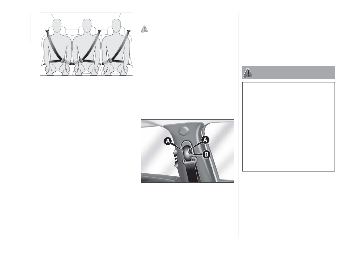
IMPORTANT When returning the rear
seat from the tilted position to the
normal operating position, take care to
refit the seat belt correctly, in order to
guarantee prompt availability every
time.
ADJUSTING THE SEAT
BELT HEIGHT
73) 74)
Five different adjustments in height are
possible.
To carry out window height adjustment,
from the top to the bottom, buttons A
fig. 70 (located on both sides of handle
B) must be pressed simultaneously
(towards each other), and the handle
must be slid downwards.
To carry out window height adjustment,
from the top to the bottom, handle B
must be slid (without pressing
anything).
Always adjust the height of the seat
belts to fit the person wearing it: this
precaution could greatly reduce the risk
of injury in the event of collision.
Correct adjustment is obtained when
the belt passes approximately half way
between the shoulder and the neck.
WARNING
71) Never press button C when travelling.
72) Remember that, in the event of an
accident, the rear seat passengers not
wearing seat belts are exposed to a very
serious risk and also represent a serious
danger for the front seat occupants.
73) Make height adjustment of the seat
belts when the car is stationary.
74) After the height adjustment, always
check that the grip is locked in one of the
preset positions. To do this, with button A
released, exert further pressure
downwards to allow the locking device to
click if the grip has not been released in
one of the possible positions.
69
F1B0382C
70
F1B0103C
88
SAFETY
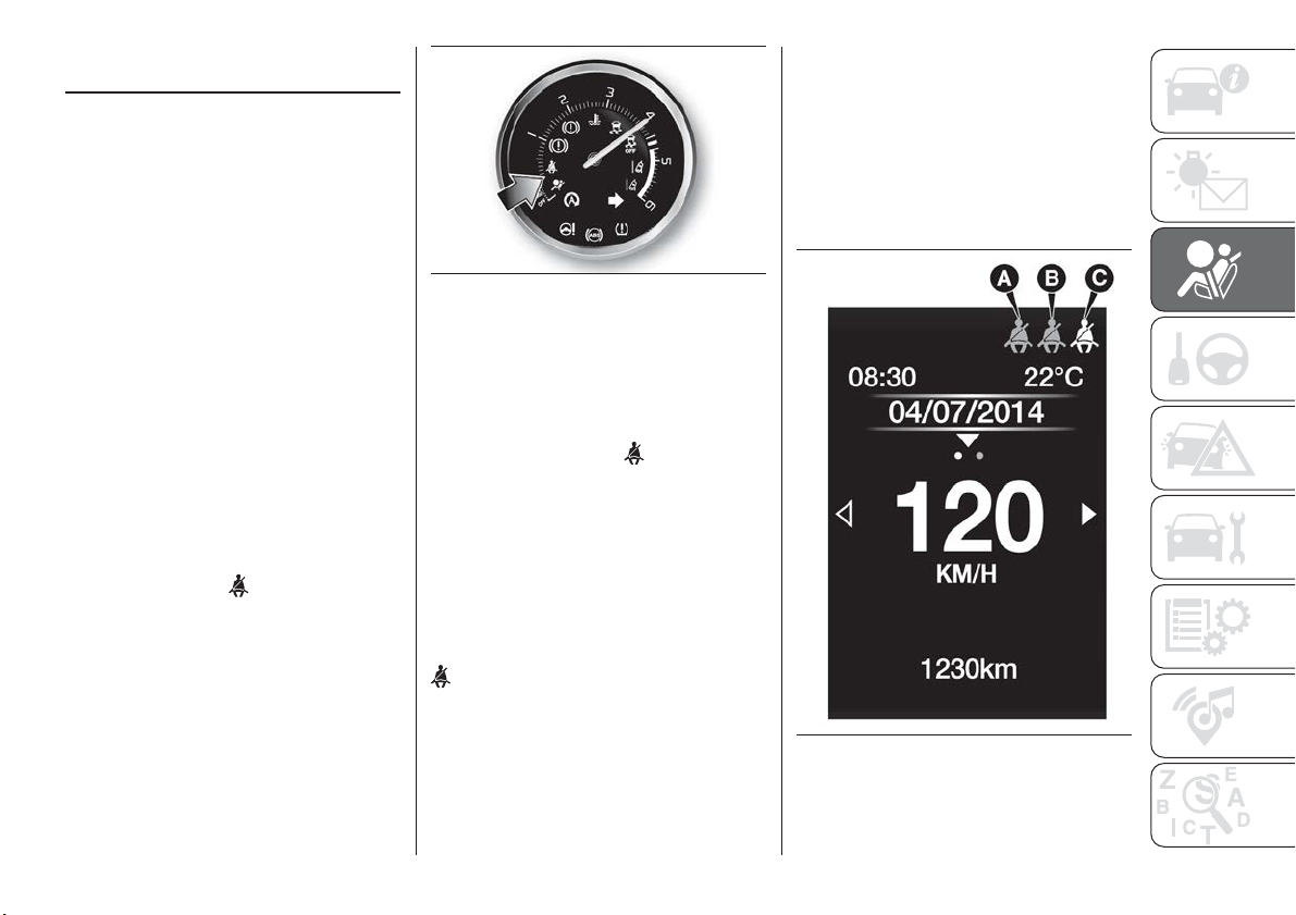
SBR (Seat Belt
Reminder) SYSTEM
The SBR system warns the passengers
of the front and rear (where provided)
seats if their seat belt is not fastened.
The system signals unfastened seat
belts with visual warnings (warning light
on in the instrument panel and symbols
on the display) and an acoustic signal
(see the following paragraphs).
NOTE To deactivate the acoustic
warning permanently go to a Fiat
Dealership. The acoustic warning can
be reactivated at any time through the
display Menu (see the "Display"
paragraph in the “Knowing the
instrument panel” chapter).
FRONT SEAT BELT
WARNING LIGHT
BEHAVIOUR
When the ignition device is turned to
MAR, warning light
(see fig. 71 )
lights up for a few seconds, regardless
of the status of the front seat belts.
With vehicle at a standstill, if the driver
side seat belt or the passenger side
seat belt (with occupant present) is
unfastened, the warning light stays on
constantly.
As soon as the threshold of 8 km/h is
exceeded for a few seconds with driver
or passenger side (with passenger
present) seat belts unfastened, an
acoustic warning is activated together
with the flashing of the
warning light
for approximately 105 seconds.
When this cycle of warnings is activated
it will stay on for its entire length
(regardless of the vehicle speed) or until
the seat belts are fastened again.
When the reverse is engaged, during
the cycle of warnings, the acoustic
signal is deactivated and the
warning light turns on constantly.
The cycle of warnings will be
reactivated as soon as speed exceeds
8 km/h again.
REAR SEAT BELT ICON
BEHAVIOUR
The icons are shown on the display
(fig. 72 versions with colour display or
fig. 73 versions with monochromatic
display) after a few seconds have
elapsed since the ignition device is
turned to MAR.
The icons will disappear after
approximately 30 seconds or after the
seat belts are fastened.
71
F1B0104C
72
F1B0105C
89
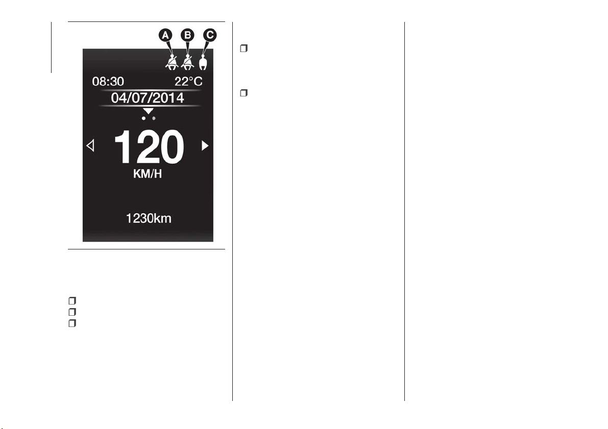
The icons on the display represent the
following (as applicable):
A: rear left seat belt fastened;
B: rear central seat belt fastened;
C: rear right seat belt unfastened.
The icons are displayed according to
the corresponding seat belts in the rear
seats, and stay on for about
30 seconds from the last seat belt
status change:
if the seat belt is fastened the
corresponding icon will appear as
shown in A and B (green on the colour
display);
if the seat belt is unfastened the
corresponding icon will appear as
shown in C (red on the colour display);
If a rear seat belt is unfastened, an
acoustic warning (3 "beeps") will be
activated along with the relevant icon
lighting up in the display.
Furthermore the icons will light up again
for 30 seconds each time one of the
doors is closed.
The icon will turn green after the
corresponding seat belt has been
fastened.
The rear seat icons will go out,
regardless of the state of the belt (red
icon or green icon), approximately
30 seconds after the last warning.
IMPORTANT NOTES
As far as the rear seats are concerned,
the SBR system will only indicate
whether the seat belts are unfastened
(red icon) or fastened (green icon), not
the presence of any passengers.
For the rear seats, the icons will activate
a few seconds after the ignition device
has been turned to MAR, regardless of
the status of the seat belts (even if the
seat belts are all fastened).
All the warning lights/icons will come on
when at least one belt changes from
fastened to unfastened status or vice
versa.
73
F1B0106C
90
SAFETY
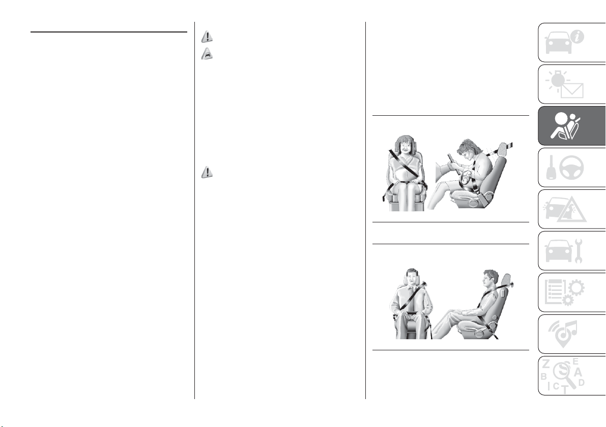
PRE-TENSIONERS
The car is equipped with seat belt
pretensioners for the front and rear side
seats. These draw the seat belts back
by several centimetres in the event of a
strong frontal impact to ensure that the
seat belts adhere perfectly to the
occupants' bodies before retention
begins.
It is evident that the pretensioners have
been activated when the belt withdraws
toward the retractor.
The front car seats are also equipped
with a second pretensioner (fitted in the
kick plate area). Its activation is
signalled by the metal cable shortening.
A slight discharge of smoke may be
produced during the activation of the
pretensioner which is not harmful and
does not involve any fire hazard.
The pretensioner does not require any
maintenance or lubrication: any
changes to its original conditions will
invalidate its efficiency.
If, due to unusual natural events (floods,
sea storms, etc.), the device has been
affected by water and/or mud, contact
a Fiat Dealership to have it replaced.
IMPORTANT To obtain the highest
degree of protection from the action of
the pretensioner, wear the seat belt
tight to the chest and pelvis.
LOAD LIMITERS
75)
41)
To increase safety in the event of an
accident, the front seat belt retractors
contain a device which controls the
force acting on the chest and shoulders
during the belt restraining action in the
event of a frontal collision.
GENERAL
INSTRUCTIONS FOR
USING THE SEAT BELTS
76) 77) 78)
Seat belts are also to be worn by
pregnant women: the risk of injury in the
case of impact is greatly reduced for
them and the unborn child if they are
wearing a seat belt.
Pregnant women must position the
lower part of the belt very low down so
that it passes over the pelvis and under
the abdomen fig. 74. While pregnancy
progresses, the driver must adjust both
seat and steering wheel to have full
control over the car (pedals and
steering wheel must be easy to
access). The maximum clearance
should be kept between the abdomen
and the steering wheel.
The seat belt strap must not be twisted.
The upper part must pass over the
shoulder and cross the chest
diagonally. The lower part must adhere
to the pelvis fig. 75, not to the
abdomen of the occupant. Do not use
devices (clips, etc.) to hold the seat belt
away from your body.
74
F1B0107C
75
F1B0108C
91
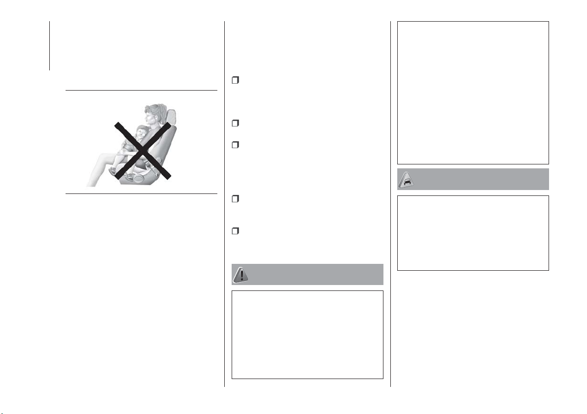
Each seat belt must be used by only
one person. Never travel with a child
sitting on the passenger's lap and a
single belt to protect them both fig. 76.
In general, do not place any objects
between the person and the belt.
SEAT BELTS
MAINTENANCE
For keeping the seat belts in efficient
conditions, carefully observe the
following warnings:
always use the seat belt well
stretched and never twisted; make sure
that it is free to run without
obstructions;
check seat belt operation as follows:
attach the seat belt and pull it hard;
replace the seat belt after an
accident of a certain severity even if it
does not appear to be damaged.
Always replace the seat belt if the
pretensioners were deployed;
prevent the retractors from getting
wet: their correct operation is only
guaranteed if water does not get inside;
replace the seat belt when it shows
wear or cuts.
WARNING
75) The pretensioner may be used only
once. Contact a Fiat Dealership to have it
replaced after it has been deployed.
76) Removing or otherwise tampering with
pretensioner and seat belt components is
strictly prohibited. Any intervention on
these components must be performed by
qualified and authorised technicians.
Always go to a Fiat Dealership.
77) For maximum safety, keep the backrest
upright, lean back into it and make sure the
seat belt fits closely across your chest and
pelvis. Always fasten the seat belts for both
the front and rear seats! Travelling without
wearing seat belts will increase the risk of
serious injury and even death in the event
of an accident.
78) If the belt has been subjected to high
levels of stress, for example after an
accident, it should be changed completely
together with the attachments, attachment
fixing screws and the pretensioner. In fact,
even if the belt has no visible defects, it
may have lost its resilience.
IMPORTANT
41) Operations which lead to impacts,
vibrations or localised heating (over 100°C
for a maximum of six hours) in the area
around the pretensioner may cause
damage or make it deploy. Contact a Fiat
Dealership should intervention be
necessary on these components.
76
F1B0109C
92
SAFETY
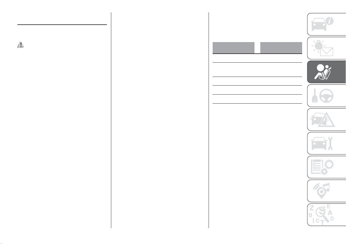
CHILD RESTRAINT
SYSTEMS
CARRYING CHILDREN
SAFELY
79) 80) 81) 82)
For optimal protection in the event of an
impact, all occupants must be seated
and wearing adequate restraint
systems, including newborn and other
children!
This prescription is compulsory in all EC
countries according to EC Directive
2003/20/EC.
Children below the height of
1.50 metres and up to 12 years must
be protected with suitable restraint
systems and be seated on the rear
seats.
Statistics on accidents indicate that the
rear seats offer greater safety for
children.
Compared with an adult, a child's head
is larger and heavier in proportion to
their body and the child's muscular and
bone structures are not fully developed.
Therefore, correct restraint systems
other than adult seat belts are
necessary, to reduce as much as
possible the risk of injuries in the event
of an accident, braking or sudden
manoeuvre.
Children must be seated safely and
comfortably. As far as the
characteristics of the child seats used
allow, you are advised to keep children
in rear facing child seats for as long as
possible (at least until 3–4 years old),
since this is the most protected position
in the event of an impact.
The choice of the most suitable child
restraint system depends on the weight
and size of the child. There are various
types of child restraint systems, which
can be secured to the car by means of
the seat belts or with the ISOFIX/i-Size
anchorages.
It is recommended to always choose
the restraint system most suitable for
the child; for this reason always refer to
the Owner Handbook provided with the
child restraint system, to be sure that it
is of the right type for the children it is
intended for.
In Europe the characteristics of child
restraint systems are ruled by the
regulation ECE-R44, dividing them into
five weight groups:
Group Weight range
Group0 upto10kg
Gr
oup 0+
up to 13 kg in
weight
Group 1 9-18 kg
Group 2 15 - 25 kg
Group 3 22 - 36 kg
The ECE-R44 standard was recently
paired with the ECE R-129 regulation,
which defines the characteristics of the
new i-Size child restraint systems (see
the "Suitability of passenger seats for
i-Size child restraint system use"
paragraph for more information).
All restraint devices must bear the
type-approval data, together with the
control mark, on a label solidly fixed to
the child restraint system which must
never be removed.
Lineaccessori MOPAR
®
includes child
restraint systems for each weight
group. These devices are
recommended having been specifically
designed for Fiat vehicles.
93
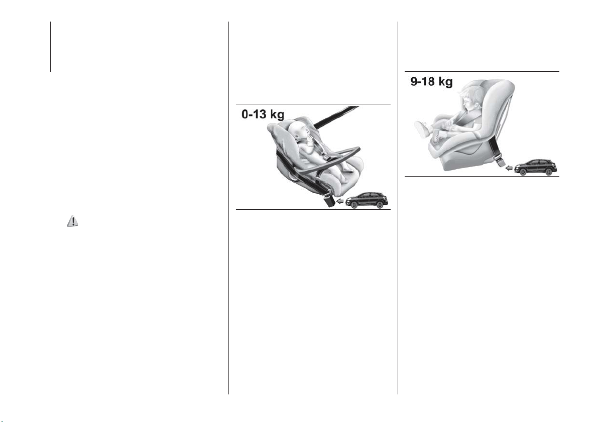
WARNING In order to be correctly
installed in the car, some universal child
seats need a (base) accessory sold
separately from the car seat
manufacturer. Therefore, FCA
recommends confirming the retailer if
the desired child seat can be installed in
the car by having it done, before buying
the seat.
FITTING A CHILD
RESTRAINT SYSTEM
WITH SEAT BELTS
The Universal child restraint systems
installed with the seat belts only are
type-approved on the basis of the ECE
R44 standard and are divided into
various weight groups.
83) 84) 85) 86)
IMPORTANT The figures are indicative
and provided for assembly purposes
only. Fit the child restraint system
according to the instructions, which
must be included.
Group 0 and 0+
Infants up to 13 kg must be carried with
a rearward facing child restraint system
of a type as shown in fig. 77 which,
supporting the head, does not induce
stress on the neck in the event of
sudden decelerations.
The child restraint system is secured by
the vehicle seat belts, as shown in
fig. 77 and it must restrain the child in
turn with its own belts.
Group 1
Children of weight from 9 to 18 kg may
be carried in forward facing child
restraint systems fig. 78.
77
F1B0110C
78
F1B0111C
94
SAFETY
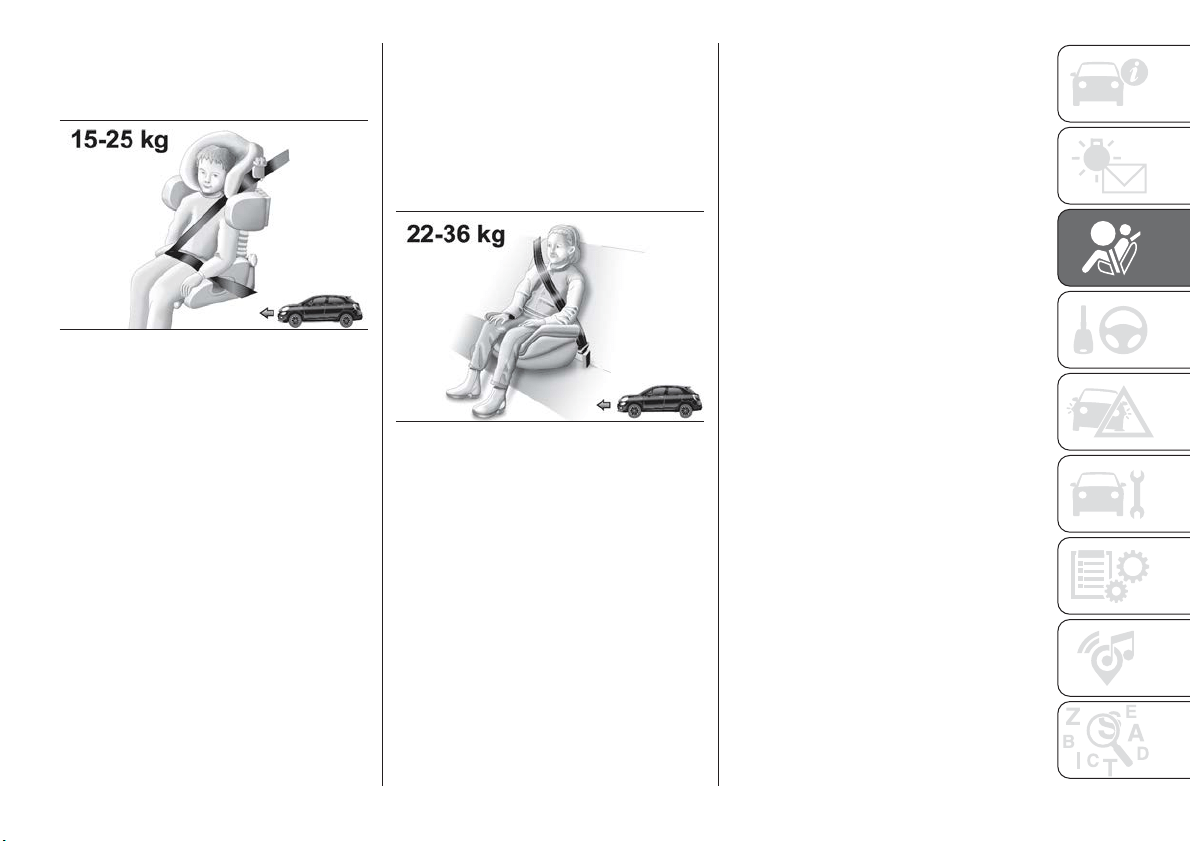
Group 2
Children from 15 to 25 kg may use the
vehicle seat belts directly fig. 79.
In this case, the child restraint system is
used to position the child correctly with
respect to the seat belts so that the
diagonal belt section crosses the child’s
chest and not the neck, and the lower
part is snug on the pelvis not the
abdomen.
Group 3
For children between 22 and 36 kg,
there are dedicated restraint systems
that allow the seat belt to be worn
correctly.
The fig. 80 shows the correct child
positioning on the rear seat.
Children over 1.50 m in height can wear
seat belts like adults.
79
F1B0112C
80
F1B0113C
95
PASSENGER SEAT COMPLIANCE WITH REGULATIONS ON UNIVERSAL CHILD
RESTRAINT SYSTEM USE
According to the European Directive 2000/3/EC the suitability of each passenger seat position for the fixing of universal child
restraint systems is shown in the following table:
Positioning the “Universal” child restraint system
Group Weight groups
Front passenger (*)
Rear central
passenger
Rear side
passengers
Airbag enabled Airbag disabled
Group 0, 0+ up to 13 kg X U X U
Gr
oup 1 9-18 kg X U X U
Group 2 15-25 kg U U X U
Group 3 22-36 kg U U X U
X = Restraint system not suitable for children in this weight category.
U = suitable for child restraint systems of the “Universal” category, according to European Standard EEC-R44 for the specified
“Groups”.
(*) IMPORTANT NEVER fit rearward facing child restraint systems on the front seat with an active passenger side airbag. If you
wish to fit a rearward-facing child restraint system in the front passenger seat, first deactivate the relative airbag (see
instructions in the paragraph "Supplementary protection system (SRS) – Airbag”).
96
SAFETY
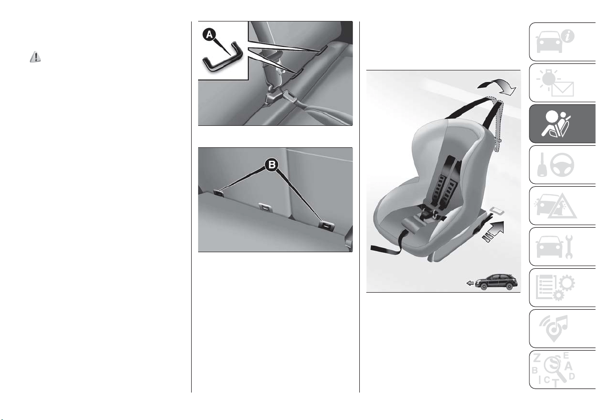
INSTALLING AN ISOFIX
CHILD RESTRAINT
SYSTEM
87) 88) 89)
The rear side seats of the car are
equipped with ISOFIX anchors, for
fitting child restraint systems quickly,
simply and safely. The ISOFIX system
lets you install the ISOFIX child
restraining system without using the car
seat belts but connecting them directly
to the car seat with three anchors in the
car.
Traditional child restraint systems can
be fitted alongside ISOFIX child restraint
systems on different seats in the same
car
To install an ISOFIX child restraint
system, attach it to the two metal
anchorages A fig. 81 located where the
rear seat cushion meets the backrest,
then fix the upper strap (available
together with the restraint system) to
the dedicated anchorage B
fig. 82 located at the bottom behind the
backrest.
As an example, fig. 83 shows an
example of a Universal ISOFIX child
restraint system for weight group 1.
IMPORTANT The fig. 83 is indicative
and for assembly purposes only. Fit the
child restraint system according to the
instructions, which must be included.
81
F1B0114C
82
F1B0115C
83
F1B0116C
97
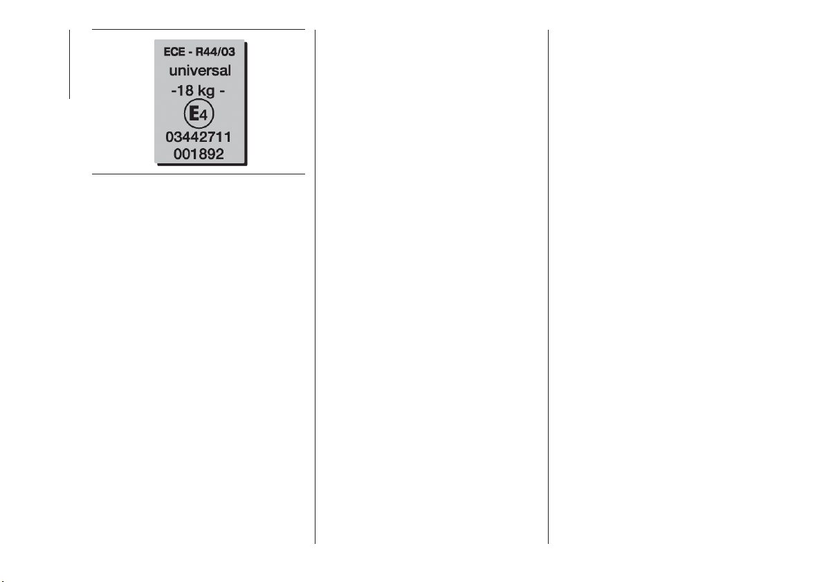
NOTE When a Universal ISOFIX child
restraint system is used, only ECE R44
"ISOFIX Universal” (R44/03 or further
upgrades), type-approved child restraint
systems can be used fig. 84.
84
F1B0117C
98
SAFETY
SUITABILITY OF PASSENGER SEATS FOR ISOFIX CHILD RESTRAINT SYSTEM USE
ISOFIX POSITIONS ON THE CAR
Weight categories Size category Device Front passenger
Rear side
passengers
Rear central
passenger
Group 0 (up to 10 kg) E ISO/R1
XILX
Group 0+ (up to 13 kg)
E ISO/R1
XILX
D ISO/R2
XILX
C ISO/R3
X IL (*) X
Group 1 (from 9 up to
18 kg)
D ISO/R2
XILX
C ISO/R3
X IL (*) X
B ISO/F2
X
IUF
- IL
X
B1 ISO/F2X
X
IUF
- IL
X
A ISO/F3
X
IUF
- IL
X
X ISOFIX position not suitable for ISOFIX child protection systems for this weight and/or size category.
IL Suitable for ISOFIX child restraint systems of the "Specific for the vehicle", "Restricted", or "Semiuniversal" categories, approved for this type of vehicle.
IL (*) The ISOFIX child restraint system can be installed by adjusting the front seat.
IUF Suitable for forward facing ISOFIX child restraint systems in the Universal category and type-approved for the use in the weight group.
NOTE: The other weight groups are covered by specific ISOFIX child restraint systems, which can be used only if specifically
tested for this car (see list of cars provided with the child restraint system).
99
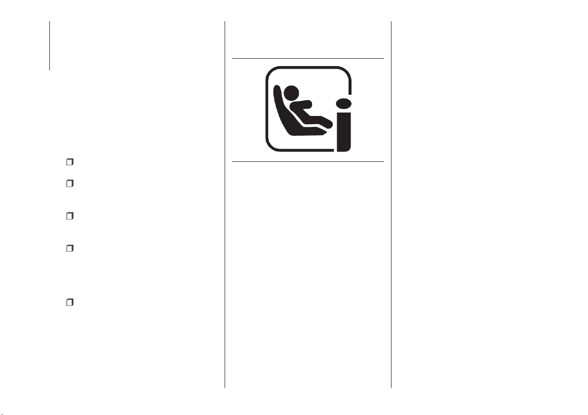
SUITABILITY OF
PASSENGER SEATS FOR
i-Size CHILD RESTRAINT
SYSTEM USE
The rear side seats of the vehicle are
type-approved to house the
state-of-the-art i-Size child restraint
systems.
These child restraint systems, built and
type-approved according to the i-Size
(ECE R129) standard, ensure better
safety conditions to carry children on
board a vehicle:
the child must be transported
rearward facing until 15 months;
child restraint system protection is
increased in the event of a side
collision;
the use of the ISOFIX system is
promoted to avoid faulty installation of
the child restraint system;
efficiency in the choice of the child
restraint system, which isn't made
according to weight anymore but
according to the child's height, is
increased;
compatibility between the vehicle
seats and the child restraint systems is
better: the i-Size child restraint systems
can be considered as "Super ISOFIX";
this means that they can be perfectly
fitted in type-approved i-Size seats, but
can also be fitted in ISOFIX (ECE R44)
type-approved seats.
NOTE The vehicle seats, i-Size
type-approved, are marked by the
symbol shown in fig. 85.
85
F1B0124C
100
SAFETY
The following table, according to European standard ECE 129, indicates the possibility of i-Size child restraint system
installation.
i-Size POSITIONS ON THE VEHICLE
Device Front passenger
Rear side
passengers
Rear central
passenger
i-Size child restraint systems
ISO/R2
X i-U X
ISO/F2 X i-U X
101
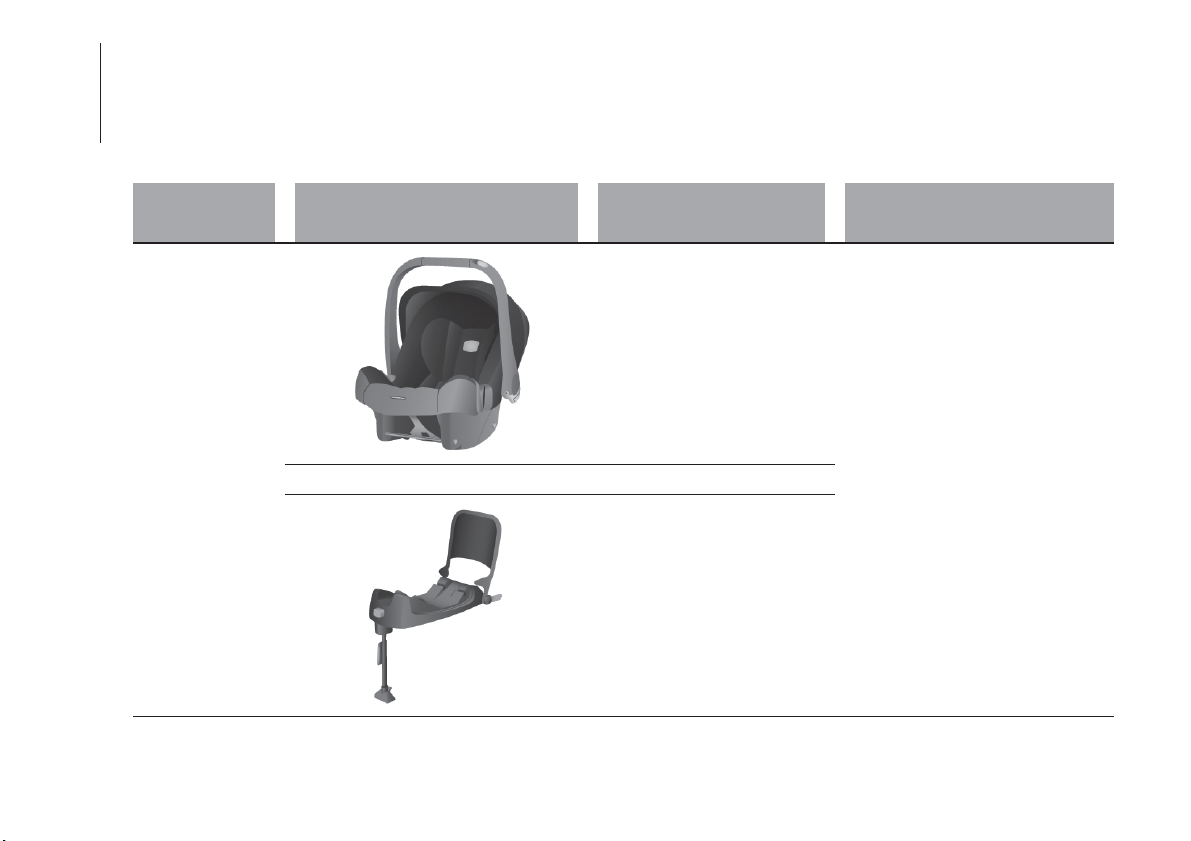
CHILD RESTRAINT SYSTEMS RECOMMENDED BY FCA FOR YOUR FIAT 500X
Lineaccessori MOPAR
®
includes a complete range of child restraint systems to be fixed using the seat belt with three
anchorage points or the ISOFIX anchorages.
IMPORTANT FCA recommends fitting the child restraint system according to the instructions, which must be included.
Weight group Child restraint system
Type of child restraint
system
Child restraint system installation
Group 0+: from
birth
to 13 kg
Britax Baby Safe plus
Approval number: E1 04301146
Fiat order code: 71806415
Universal/ISOFIX child restraint system.
It must be installed facing rearwards,
using the vehicle seat belts only, or the
dedicated ISOFIX base (which can be
purchased separately) and the vehicle
ISOFIX anchorages.
It must be fitted on the rear outer
seats.
++
Britax Baby Safe ISOFIX base
Fiat order code: 71806416
102
SAFETY
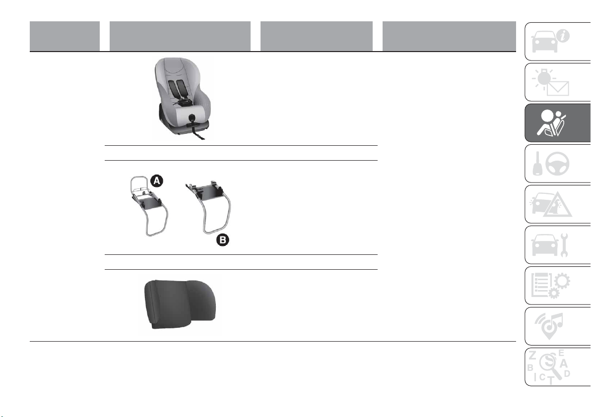
Weight group Child restraint system
Type of child restraint
system
Child restraint system installation
Group 1: from 9
up
to 18 kg
Fair G0/1S
Type-approval number:
E4 04443718
Fiat order code: 71807388
Universal/ISOFIX child restraint system.
It can be fitted forward facing/rearward
facing using only the vehicle seat belts
or the Isofix anchorages.
FCA recommends fitting it using the
rearward facing ISOFIX platform (RWF
specific "G" type - to be purchased
separately) or the forward facing
ISOFIX platform (FWF specific "A" type
- to be purchased separately), the rigid
head restraint (to be purchased
separately) and the ISOFIX anchorages
for the vehicle.
It must be fitted on the rear outer
seats.
++
Reference A: Fair ISOFIX
RWF platform, "G" type for G
0/1S
Fiat order code: 71807455
or
Reference B: Fair ISOFIX
FWF platform, "A" type for G
0/1S
Fiat order code: 71805364
++
FAIR head restraint
Fiat order code: 71807387
103
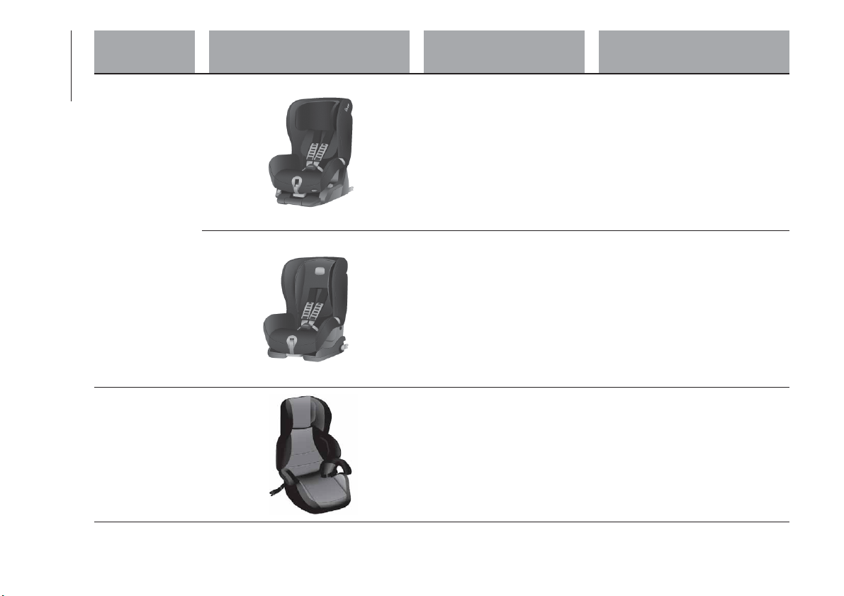
Weight group Child restraint system
Type of child restraint
system
Child restraint system installation
Group 1: from
9u
pto18kg
Britax Safefix TT
Approval number: E1 04301199
Fiat order code: 71805956
It must be fitted forward facing only,
using the ISOFIX attachments and the
upper strap, provided with the child
restraint system.
It must be fitted on the rear outer
seats.
Britax Roemer Duo Plus
Type-approval number:
E1 04301133
Fiat order code: 71803161
It must be fitted forward facing only,
using the ISOFIX attachments and the
upper strap, provided with the child
restraint system.
It must be fitted on the rear outer
seats.
Group 2: from
15 kg to 36 kg
Fair Junior Fix
Type-approval number:
E4 04443721
Fiat order code: 71806570
It can only be fitted facing forwards,
using the three-point seat belt and the
ISOFIX anchorages of the vehicle, if
present.
104
SAFETY
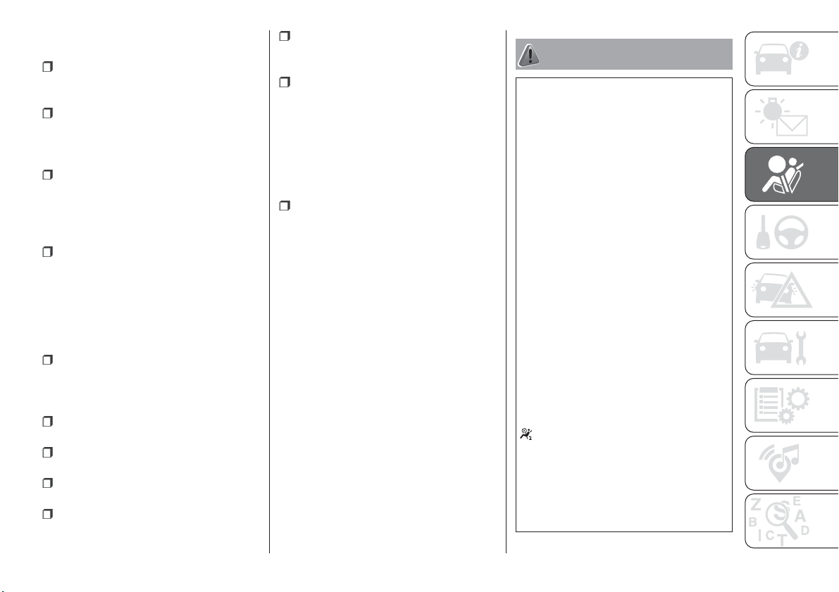
Main recommendations to carry
children safely
Install the child restraint systems on
the rear seat, which is the most
protected position in a crash.
Keep children in rearward-facing
child restraint systems for as long as
possible, ideally until they are 3–4 years
old.
If the passenger's front airbag is
deactivated always check the
dedicated warning light on the trim
located on the dashboard to make sure
that it has actually been deactivated.
Carefully follow the instructions
supplied with the child restraint system.
Keep the instructions in the car along
with the other documents and this
handbook. Do not use second-hand
child restraint systems without
instructions.
Only one child is to be strapped into
each restraint system; never carry two
children using one child restraint
system.
Always check that the seat belts do
not rest on the child’s neck.
Always check that the seat belt is
well fastened by pulling on it.
While travelling, do not let the child
sit incorrectly or unfasten the belts.
Never allow a child to put the belt's
diagonal section under an arm or
behind their back.
Never carry children on your lap,
even newborns. No-one can hold a
child in the case of a crash.
If the car has been involved in a road
accident, replace the child restraint
system with a new one. In addition, and
depending on the type of child restraint
system installed, replace the Isofix
anchorages or the seat belt with which
the child restraint system was
connected.
For any child restraint system
mounted facing the direction of travel of
the vehicle on the external rear seats,
independently of its weight group,
mount it after removing the
corresponding rear seat head restraint.
This does not apply to child restraint
systems that consist only of a cushion
(without backrest). You should install
such child restraint systems when the
corresponding head restraint is
mounted. Any removed head restraints
must be kept in the car are refitted if the
seat is used by an adult occupant.
WARNING
79) SEVERE DANGER When a front
passenger airbag is fitted, do not install
rearward facing child restraint systems on
the front passenger seat. Deployment of
the airbag in an accident could cause fatal
injuries to the child regardless of the
severity of the collision. It is advisable to
always carry children in a child restraint
system on the rear seat, which is the most
protected position in the event of a
collision.
80) On the sun visor there is a label with
suitable symbols reminding the user that it
is compulsory to deactivate the airbag if a
rearward facing child restraint system is
fitted. Always comply with the instructions
on the passenger side sun visor (see the
"Supplementary Restraint System (SRS) -
Airbag" paragraph).
81) Should it be necessary to carry a child
on the passenger side front seat in a rear
facing child restraint system, the passenger
side front airbag and side bag must be
deactivated through the display main menu
(see the "Display" paragraph, "Knowing the
instrument panel" chapter), verifying
deactivation by checking whether the
OFF LED has switched on in the trim
located on the dashboard. Move the
passenger's seat as far back as possible to
avoid contact between the child seat and
the dashboard.
82) Do not move the front or rear seat if a
child is seated on it or on the dedicated
child restraint system
105
83) Incorrect fitting of the child restraint
system may result in an inefficient
protection system. In the event of an
accident the child restraint system may
become loose and the child may be
injured, even fatally. When fitting a restraint
system for newborns or children, strictly
comply with the instructions provided by
the Manufacturer.
84) When the child restraint system is not
used, secure it with the seat belt or with
the ISOFIX anchorages, or remove it from
the vehicle. Do not leave it unsecured
inside the passenger compartment. In this
way, in the case of sudden braking or an
accident, it will not cause injuries to the
occupants.
85) After installing a child restraint system,
do not move the seat: always remove the
child restraint system before making any
adjustment.
86) Always make sure that the diagonal
section of the seat belt does not pass
under the arms or behind the back of the
child. In the event of an accident the seat
belt will not be able to secure the child,
with the risk of injury, including fatal injury.
Therefore the child must always wear the
seat belt correctly.
87) Do not use the same lower anchorage
to install more than one child restraint
system.
88) If a Universal ISOFIX child seat is not
fixed to all three anchorages, the child seat
will not be able to protect the child
correctly. In a crash, the child could be
seriously or fatally injured.
89) Fit the child restraint system when the
car is stationary. The child restraint system
is correctly fixed to the brackets when you
hear the click. Follow the instructions for
assembly, disassembly and positioning that
the Manufacturer must supply with the
child restraint system.
SUPPLEMENTARY
RESTRAINT SYSTEM
(SRS) - AIRBAG
The vehicle is equipped with:
front driver airbag;
front passenger airbag;
driver and passenger front side bags
for pelvis, chest and shoulder
protection (Side bags);
front and rear side passenger side
bags for head protection (window bag)
driver's knee bag (where provided).
The location of the airbags on the
vehicle is marked by the word
"AIRBAG" in the middle of the steering
wheel, on the dashboard, on the side
trim or on a label placed next to the
airbag deployment area.
FRONT AIRBAGS
The front driver/passenger airbags and
the driver knee bag (where provided)
protect the front seat occupants in the
event of frontal impacts of medium/high
severity, by placing the bag between
the occupant and the steering wheel or
dashboard.
Therefore non-activation of airbags in
other types of collisions (side impacts,
rear shunts, roll-overs, etc.) does not
indicate a system malfunction.
106
SAFETY
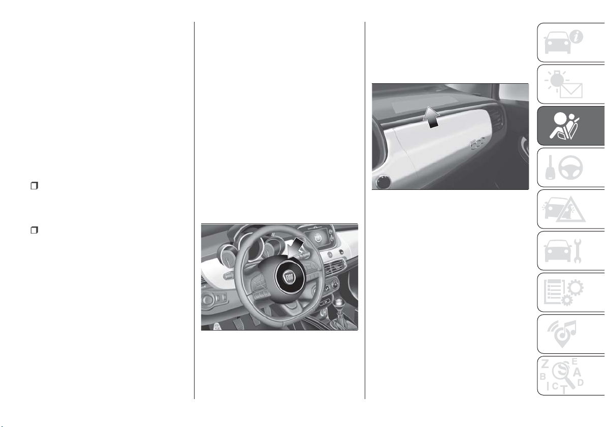
Driver and passenger front airbags are
not a replacement of but
complementary to the seat belts, which
should always be worn, as specified by
law in Europe and most non-European
countries.
In a crash, those not wearing a seat
belt are projected forwards and may
come into contact with the bag which is
still inflating. The protection offered by
the bag is compromised in these
circumstances.
Front airbags may not activate in the
following situations:
frontal impacts against highly
deformable objects not involving the
front surface of the car (e.g. wing
collision against guard rail, etc.);
car wedging under other cars or
protective barriers (e.g. trucks or guard
rails).
Failure to activate in the conditions
described above is due to the fact that
they may not provide any additional
protection compared with seat belts, so
their activation would be inappropriate.
In these cases, non-deployment does
not indicate a system malfunction.
The driver's and passenger's front
airbags have been designed and
calibrated to protect front seat
occupants wearing seat belts.
At their maximum inflation, their volume
fills most of the space between the
steering wheel and the driver and
between the dashboard and the
passenger.
The airbags are not deployed in the
event of minor frontal impacts (for which
the restraining action of the seat belts is
sufficient). Seat belts must always be
worn. In the event of a frontal collision,
they ensure the correct positioning of
the occupant.
Front airbag driver's side
This consists of an instantly inflating
bag contained in a special
compartment in the centre of the
steering wheel fig. 86.
Passenger front airbag
This consists of an instantly inflating
bag contained in a special recess in the
dashboard fig. 87; this bag has a larger
volume than that of the driver's.
Passenger's front airbag and child
restraint systems
Rearward facing child restraint systems
must NEVER be fitted on the front seat
with an active passenger airbag since in
the event of an impact the airbag
activation may cause fatal injuries to the
transported child.
ALWAYS comply with the instructions
on the label stuck on the passenger
side sun visor fig. 88.
86
F1B0629C
87
F1B0126C
107
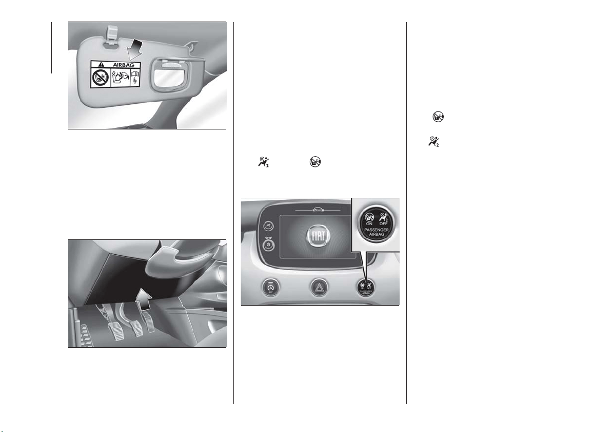
Driver knee bag
(where provided)
It is located in a specific compartment
arranged under the dashboard under a
specific cover fig. 89. It provides
additional protection in the event of a
frontal collision.
Deactivating passenger front airbag
and seat-mounted side bag for
pelvis, chest and shoulders
protection
If a child must be carried on the front
seat in a rearward facing child restraint
system, deactivate the passenger side
front airbag and front side bag.
To deactivate the airbags use the
display Menu (see the instructions in the
"Display" paragraph, "Knowing the
instrument panel" chapter).
The
OFF and ON LED are
present at the centre of the instrument
panel fig. 90.
Moving the ignition device to MAR
switches on the two LEDs for about
8 seconds. If not, contact a Fiat
Dealership.
During the first seconds, the activation
of the LEDs does not actually show the
passenger protection status, but only
checks its correct operation. After a
check lasting a few seconds, the LEDs
will indicate the status of the passenger
airbag protection.
Passenger protection activated: the
LED
ON turns on fixed.
Passenger protection deactivated:
the
OFF LED switches on with a
steady light.
The LEDs may light up with various
intensity levels depending on the vehicle
conditions. The intensity may vary
during the same key cycle.
88
F1B0127C
89
F1B0132C
90
F1B0630C
108
SAFETY
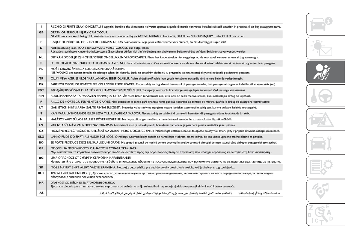
Passenger front airbag and child restraint system: WARNING
91
F1B0129C
109
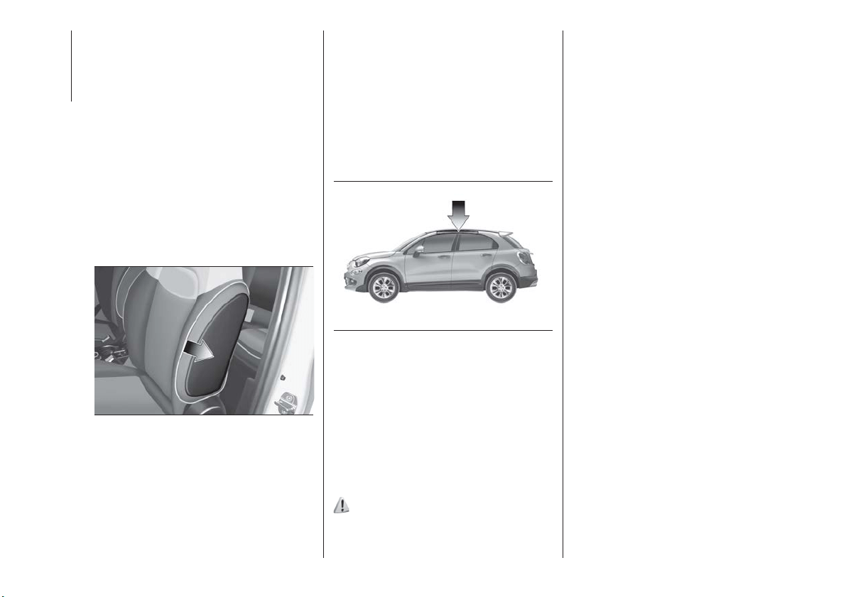
SIDE BAGS
To help increase occupants protection
in the event of side impact collisions,
the car is equipped with front side bags
and window bags.
Side bag
These consist of two bags located in
the front seat backrests fig. 92 that
protect the occupants’ pelvis, chest
and shoulder area in the event of a side
impact of medium/high severity.
They are marked by the "AIRBAG" label
sewn on the outer side of the front
seats.
Window bag
These consist of two “drop-down”
cushions, housed behind the side lining
of the roof and covered with finishing
elements fig. 93.
They are designed to protect the head
of front and rear occupants in the event
of a side collision, thanks to the wide
cushion inflation surface.
The deployment of side bags in the
event of side impacts of low severity is
not required.
In the event of a side impact, the
system provides best protection if the
passenger sits on the seat in a correct
position, thus allowing correct window
bag deployment.
90) 91) 92) 93) 94) 95) 96) 97) 98) 99) 100) 101) 102) 103) 104)
105)
Important notes
Do not wash the seats with water or
pressurised steam (wash by hand or at
automatic seat washing stations).
The front airbags and/or side bags may
be deployed in the event of sharp
impacts to the underbody of the car
(e.g. impact with steps, pavements,
potholes or road bumps etc.).
When the airbag deploys it emits a
small amount of dust: the dust is
harmless and does not indicate the
beginning of a fire. The dust may irritate
the skin and eyes however: in this case,
wash with neutral soap and water.
Airbag checking, repair and
replacement must be carried out at a
Fiat Dealership.
If the car is scrapped, have the airbag
system deactivated at a Fiat Dealership.
Pretensioners and airbags are deployed
in different ways on the basis of the
type of collision. Failure to activate one
or more of the devices does not
indicate a system malfunction.
92
F1B0130C
93
F1B0131C
110
SAFETY
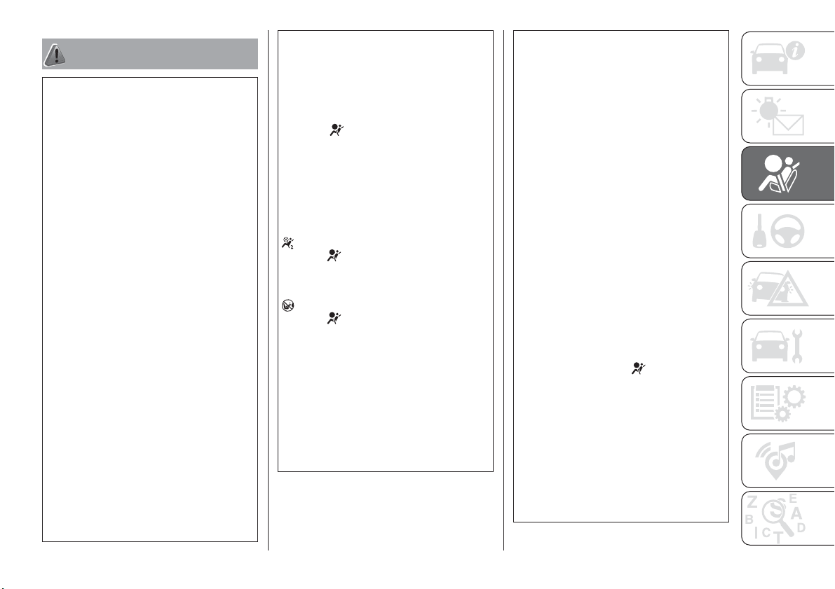
WARNING
90) Do not apply stickers or other objects
on the steering wheel, on the dashboard in
the passenger side airbag area, on side
upholstery on the roof or on the seats.
Never put objects (e.g. mobile phones) on
the passenger side of the dashboard since
they could interfere with correct inflation of
the passenger airbag and also cause
serious injury to the passengers.
91) Always drive with your hands on the
rim of the steering wheel so that the airbag
can inflate freely if required. Do not drive
with your body bent forward. Keep your
back straight against the backrest.
92) When there is an active passenger
airbag, DO NOT install rearward facing
child restraint systems on the front seat.
Deployment of the airbag in an accident
could cause fatal injuries to the child
regardless of the severity of the impact.
Therefore, always deactivate the passenger
side airbag when a rearward facing child
restraint system is installed on the front
passenger seat. The front passenger seat
must also be positioned back as far as
possible in order to prevent the child
restraint system from coming into contact
with the dashboard. Immediately reactivate
the passenger airbag as soon as the child
restraint system has been removed.
93) To deactivate the airbags using the
instrument panel menu, see the description
in the "Knowing the instrument panel"
chapter, "Menu Options" paragraph.
94) Do not affix rigid objects to the
garment hooks or support handles.
95) Do not rest your head, arms or elbows
on the door, windows or the area in which
the Window bag is located to avoid
possible injury during airbag inflation.
96) Never lean your head, arms or elbows
out of the window.
97) If, when the ignition device is turned to
MAR, the
warning light does not switch
on or stays on whilst driving, a fault may
have occurred in the restraint systems. In
this case the airbags or pretensioners may
not be deployed in an impact or, in a lower
number of cases, they may be deployed
accidentally. Contact a Fiat Dealership
immediately to have the system checked.
98) In some versions, in the event of a LED
OFF failure (located on the dashboard
trim), the
warning light on the
instrument panel turns on and the
passenger side airbags are deactivated. In
some versions, in the event of a LED
ON failure (located on the dashboard
trim), the
light on the console turns on.
99) On cars with side bags, do not cover
the front seat backrests with extra covers.
100) Do not travel carrying objects in your
lap, in front of your chest or between your
lips (pipe, pencils, etc.): they could cause
severe injury if the airbag is deployed.
101) If the car has been stolen or in the
case of attempt to steal it, if it has been
subjected to vandalism or floods, have the
airbag system checked by a Fiat
Dealership.
102) If the ignition device is at MAR, even if
the engine is switched off, airbags may be
deployed when the vehicle is stationary
and hit by another vehicle. Therefore, even
if the vehicle is stationary, when an active
front passenger airbag is fitted, DO NOT
install rearward facing child restraint
systems on the front passenger seat.
Deployment of the airbag following an
impact could cause fatal injuries to the
child. Therefore, always deactivate the
passenger side airbag when a rearward
facing child restraint system is installed on
the front passenger seat. The front
passenger seat must also be positioned
back as far as possible in order to prevent
the child restraint system from coming into
contact with the dashboard. Immediately
reactivate the passenger airbag as soon as
the child restraint system has been
removed. Also remember that, if the
ignition device is set to STOP, none of the
safety devices (airbags or pretensioners)
will be deployed in the event of collision.
Non-deployment in such cases does not
indicate a system malfunction.
103) Malfunction of the
warning light is
indicated by the activation of an airbag
failure icon and dedicated message on the
instrument panel display. The pyrotechnic
charges are not disabled. Contact a Fiat
Dealership immediately to have the system
checked
104) The airbag deployment threshold is
higher than that of the pretensioners. For
collisions in the range between the two
thresholds, it is normal for only the
pretensioners to be activated.
111

105) The airbag does not replace seat
belts but increases their efficiency.
Because front airbags are not deployed for
low-speed crashes, side collisions,
rear-end shunts or rollovers, occupants are
protected, in addition to any side bags,
only by their seat belts, which must
therefore always be fastened.
112
SAFETY

STARTING AND DRIVING
Let’s get to the "heart" of the vehicle:
seeing how you can exploit all of its
potential to the full.
We’ll look at how to drive it safely in any
situation, so that it can be a welcome
companion, with our comfort and our
wallets in mind.
STARTING THE ENGINE .......114
PARKING THE VEHICLE........115
ELECTRIC PARKING BRAKE
(EPB) ....................115
MANUAL GEARBOX ..........118
AUTOMATIC TRANSMISSION . . . .119
TWIN CLUTCH TRANSMISSION . .122
START&STOP SYSTEM ........125
SPEED LIMITER .............127
ELECTRONIC CRUISE
CONTROL ................127
ADAPTIVE CRUISE CONTROL
(ACC)....................129
MOOD SELECTOR / DRIVE MODE
(drive mode selector) .........133
PARK ASSIST SYSTEM ........135
LANE ASSIST SYSTEM (lane
crossing warning) ............137
REAR VIEW CAMERA .........139
TOWING TRAILERS ..........140
REFUELLING THE VEHICLE .....144
113
STARTING THE
ENGINE
Before starting the engine, adjust the
seat, the interior rear view mirrors, the
door mirrors and fasten the seat belt
correctly.
Never press the accelerator pedal for
starting the engine.
If necessary, messages indicating the
starting procedure can be shown on
the display.
LPG versions
The engine always starts up on petrol
independently of the previously selected
mode.
42)
ENGINE STARTING
PROCEDURE
106) 107) 108) 109)
43) 44) 45) 46)
Versions with manual gearbox
Proceed as follows:
engage the electric parking brake
and place the gear lever in neutral;
bring the ignition device to MAR. On
Diesel versions, warning light
lights
up in the instrument panel: wait for the
warning light to switch off;
fully depress the clutch pedal
without touching the accelerator;
turn the ignition device to AVV and
release it as soon as the engine starts;
if the engine does not start within
10 seconds, bring the ignition device
back to STOP and wait for
10-15 seconds before repeating the
starting procedure.
after the manoeuvre has been
repeated, if the problem persists,
contact a Fiat Dealership.
Versions with automatic
transmission
Proceed as follows:
engage the electric parking brake
and set the gear lever to P (Park) or N
(Neutral);
fully depress the brake pedal without
touching the accelerator;
set the ignition device to AVV;
if the engine does not start, bring
the ignition device back to STOP and
wait for 10-15 seconds before
repeating the starting procedure;
after the manoeuvre has been
repeated, if the problem persists,
contact a Fiat Dealership.
ENGINE STARTING
FAILURE
Starting the engine with electronic
key battery (Keyless Go) run down
or flat
If the ignition device does not respond
when the relevant button is pressed the
electronic key battery might be run
down or flat. Therefore, the system
does not detect the presence of the
electronic key on board the vehicle and
displays a dedicated message. In this
case, rest the rounded edge of the
electronic key (the side opposite the
metal insert) on the ignition device and
press the button using the electronic
key. The ignition device is thus activated
and the engine can be started.
WARNING
106) Do not try to start the engine pouring
fuel or other flammable fluid inside the
throttle body air intake: this might damage
the engine and injury people nearby.
107) It is dangerous to run the engine in
enclosed areas. The engine takes in
oxygen and releases carbon dioxide,
carbon monoxide and other toxic gases.
108) The brake servo is not active until the
engine is started, so you would need to
apply much more force than usual to the
brake pedal.
114
STARTING AND DRIVING
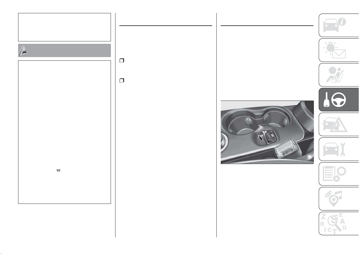
109) Do not start the engine by pushing,
towing or driving downhill. These
manoeuvres may damage the catalytic
converter.
IMPORTANT
42) There must therefore always be some
petrol in the tank to protect the petrol
pump and to guarantee temporary
switching from LPG to petrol operation, if
high performance is required.
43) We recommend that during the initial
period, or during the first 1600 km, you do
not drive to full car performance (e.g.
excessive acceleration, long journeys at top
speed, sharp braking, etc.).
44) When the engine is switched off never
leave the ignition device in the MAR
position to prevent useless current
absorption from draining the battery.
45) A quick burst on the accelerator before
turning off the engine serves absolutely no
practical purpose; it wastes fuel and is
especially damaging to turbocharged
engines.
46) Warning light
will flash after starting
or during prolonged cranking to indicate a
fault with the glow plug heating system. If
the engine starts, the vehicle can be used
as normal, but a Fiat Dealership must be
contacted as soon as possible.
PARKING THE
VEHICLE
Always remove the ignition key when
leaving the car.
When parking and leaving the car,
proceed as follows:
engage a gear (1
st
gear if facing
uphill or reverse if facing downhill) and
leave the wheels turned;
stop the engine and apply the
electric parking brake;
Block the wheels with a wedge or a
stone if the car is parked on a steep
slope.
On versions equipped with automatic
transmission or dual clutch automatic
transmission, wait for the letter P to be
displayed before releasing the brake
pedal.
IMPORTANT NEVER leave the car with
the gearbox in neutral (or, on versions
equipped with automatic transmission
or dual clutch automatic transmission,
before putting the shift lever in the P
position).
ELECTRIC PARKING
BRAKE (EPB)
The vehicle is equipped with electric
parking brake (EPB) to guarantee better
use and optimal performance
compared to a manually operated
parking brake.
The electric parking brake features a
switch, located on the central tunnel
fig. 94, a motor with caliper for each
rear wheel and an electronic control
module.
IMPORTANT Always engage the
electric parking brake before leaving the
car.
94
F1B0133C
115
IMPORTANT In addition to parking the
vehicle with the parking brake always
engaged, the wheel steered, chocks or
stones positioned in front of the wheels
(when on a steep slope), a gear must
always be engaged (the 1
st
gear with
the vehicle parked uphill or the reverse
gear with the vehicle parked downhill).
On versions with automatic
transmission, place the gear lever at P
(Park).
IMPORTANT Should the vehicle battery
be faulty, to unlock the electric parking
brake the battery must be replaced.
The electric parking brake can be
engaged in two ways:
manually pull the switch fig. 94 on
the central tunnel in the direction shown
by the arrow;
automatically in "Safe Hold" or "Auto
Apply" conditions.
Engaging the parking brake
manually
110) 117) 112)
Briefly pull the switch located on the
central tunnel to manually engage the
electric parking brake when the car is
stationary.
Noise may be heard from the rear of the
vehicle when engaging the electric
parking brake.
A slight movement of the brake pedal
may be detected when engaging the
electric parking brake with the brake
pedal pressed.
With the electric parking brake
engaged, the warning light
on the
instrument panel and the LED on the
switch fig. 94 turn on.
IMPORTANT With the EPB failure
warning light on, some functions of the
electric parking brake are deactivated.
In this case the driver is responsible for
brake activation and vehicle parking in
complete safety conditions.
If, under exceptional circumstances, the
use of the parking brake is required with
the car in motion, keep the switch on
the central tunnel pulled as long as the
brake action is necessary.
The
warning light may switch on
with the hydraulic system temporarily
unavailable; in this case braking is
controlled by the motors.
The stop lights also automatically
switch on.
Release the switch on the central tunnel
to stop the braking action with the car
in motion.
If, through this procedure, the vehicle is
braked until a speed below 3 km/h is
reached and the switch is kept pulled,
the parking brake will definitively
engage.
IMPORTANT Driving the vehicle with
the electric parking brake engaged, or
using it several times to slow down the
vehicle, may cause severe damage to
the braking system.
Releasing the electric parking
brake manually
The ignition device must be in the MAR
position in order to manually release the
parking brake. Moreover, you need to
press the brake pedal, then press the
fig. 94 switch briefly.
Noise may be heard from the rear part
of the car and a slight movement of the
brake pedal may be detected during
release.
After disengaging the electric parking
brake, the
warning light on the
instrument panel and the LED on the
switch will turn off.
If the
warning light on the
instrument panel remains on with the
electric parking brake disengaged, this
indicates a failure: in this case contact a
Fiat Dealership.
IMPORTANT On versions with
automatic transmission never use the P
(Park) position instead of the electric
parking brake. Always engage the
electric parking brake when parking the
vehicle to prevent injury or damage
caused by the unexpected movement
of the vehicle.
116
STARTING AND DRIVING

IMPORTANT For cars with manual
transmission, if the clutch pedal is
pressed all the way and then released
simultaneously with the press of the
accelerator, the electric parking brake
automatically releases.
OPERATING THE
ELECTRIC PARKING
BRAKE
The electric parking brake can operate
in the following ways:
"Dynamic operating mode": this
mode is activated by pulling the switch
fig. 94 repeatedly whilst driving;
"Static engagement and release
mode": with the car stationary, the
electric parking brake can be activated
by pulling the switch once. On the other
hand, press the switch and the brake
pedal at the same time to disengage
the brake;
“ Drive Away Release”: the electric
parking brake will automatically
disengage with the detection of the
driver’s intention to move the car
forward or in reverse. On versions with
automatic transmission, the driver’s
safety belt has to be properly fastened.
"Safe Hold": if the car speed is lower
than 3 km/h and, for the versions with
automatic transmission, the gear lever
is not in P (Park) position and the driver
intention of leaving the car is detected,
the electric parking brake will
automatically engage to hold the car in
safety conditions;
"Auto Apply": if the car speed is
lower than 3 km/h, the electric parking
brake will automatically engage with the
gear lever moved to P (Park) position
(versions with automatic transmission),
or with the ignition device at STOP
(versions with manual transmission).
The LED on the switch will light up
together with the
warning light on
the instrument panel when the parking
brake is engaged and applied to the
wheels. Each automatic parking brake
engagement can be cancelled by
pressing the switch on the central
tunnel and at the same time moving the
gear lever for the automatic
transmission to position P (Park) or the
ignition device to STOP (versions with
manual transmission). This way can be
handled by using the system Menu
Uconnect™.
SAFE HOLD
It is a safety function that automatically
engages the electric parking brake in
the event of a dangerous condition for
the vehicle.
If:
the vehicle speed is below 3 km/h;
the gear lever is not at P (Park)
(versions with automatic transmission);
the driver's seat belt is not fastened;
the driver side door is open;
no attempted operation of the brake
pedal or the accelerator pedal, or, in
versions with manual gearbox, the
clutch pedal is detected
the electric parking brake engages
automatically to prevent vehicle
movement.
The Safe Hold function can be
temporarily disabled by pressing the
switch located on the central tunnel and
the brake pedal at the same time, with
the vehicle stationary and the driver
side door open.
Once disabled, the function will activate
again when the vehicle speed reaches
20 km/h or the ignition device is moved
to STOP and then to MAR.
117
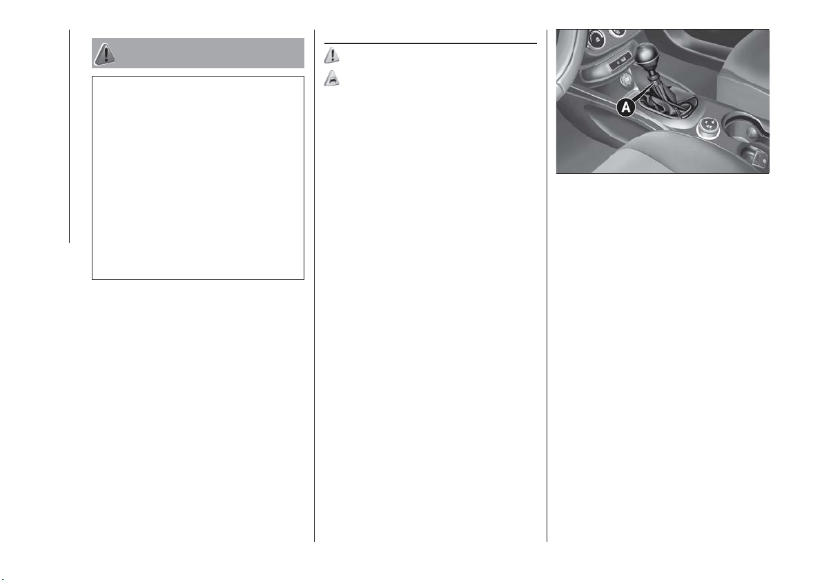
WARNING
110) In the case of parking manoeuvres on
roads on a gradient, steer the wheels,
engage the parking brake, the first gear if
uphill and the reverse if downhill; on
versions with automatic transmission, set
the lever to "P". If the car is parked on a
steep slope block the wheels with a wedge
or stone.
111) Never leave children alone in an
unattended vehicle; make sure that when
you move away from the vehicle, you have
the key with you.
112) The electric parking brake must
always be engaged when leaving the
vehicle.
MANUAL GEARBOX
113)
47)
To engage the gears, press the clutch
pedal fully and put the gear lever into
the required position (the diagram for
gear engagement is shown on the knob
).
To engage 6
th
gear (if present), operate
the lever by pressing it towards the right
in order to avoid engaging 4
th
gear by
mistake. The same applies to the shift
from 6
th
to 5
th
gear.
1.4 Turbo Multi Air - 1.6 Multijet -
2.0 Multijet manual transmission
versions: To engage reverse R from
neutral, lift the ring 1 fig. 95 under the
knob and at the same time move the
lever to the left and then forwards.
1.6 E.Torq versions: To engage
reverse gear R from neutral, move the
lever to the right and then backwards.
IMPORTANT Reverse can only be
engaged when the car is completely
stationary. For 1.6 E.Torq versions: with
the engine running, wait for at least
2 seconds with the clutch pedal fully
pressed before engaging reverse to
prevent damage to the gears and
“grating”.
IMPORTANT The clutch pedal should
be used only for gear changes. Do not
drive with your foot resting on the
clutch pedal, however lightly. In some
circumstances, the electronic clutch
control could cut in by interpreting the
incorrect driving style as a fault.
95
F1B0134C
118
STARTING AND DRIVING
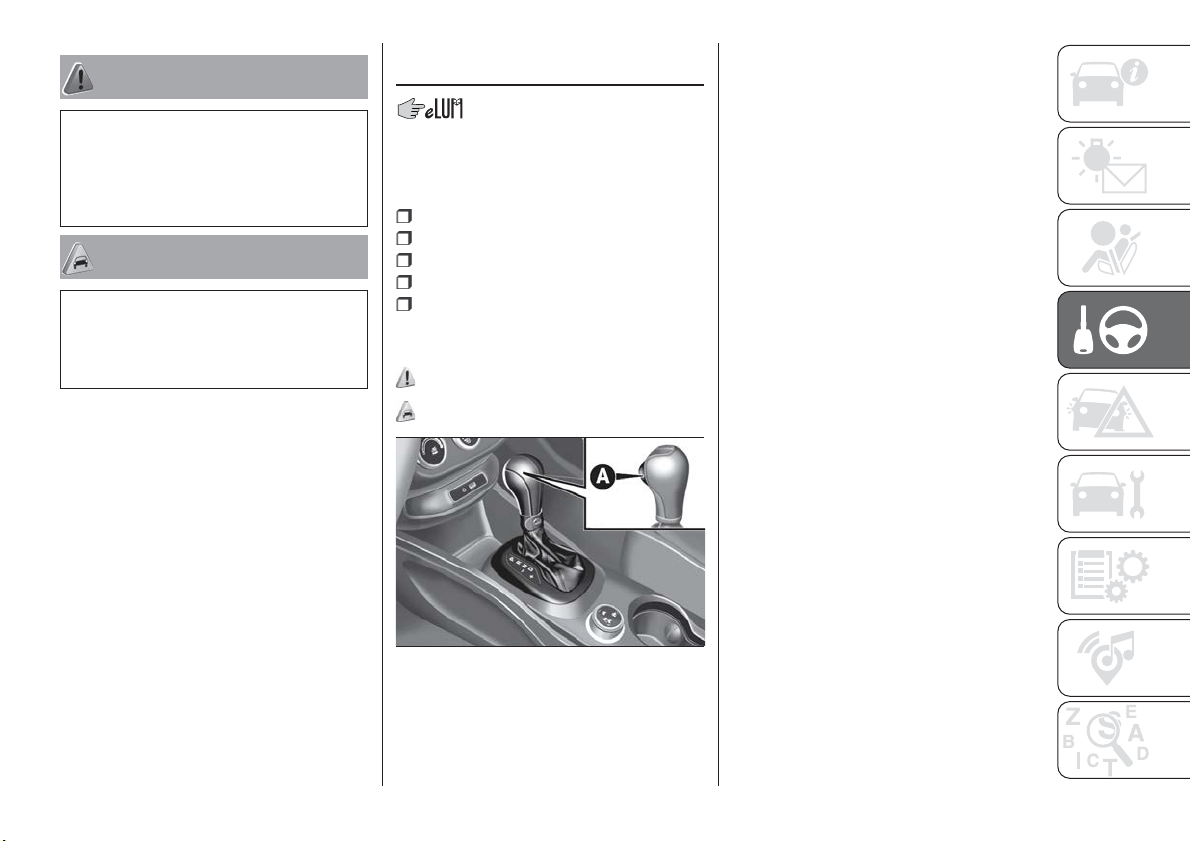
WARNING
113) Depress the clutch pedal fully to
change gear correctly. It is therefore
essential that there is nothing under the
pedals: make sure the mats are lying flat
and do not get in the way of the pedals.
IMPORTANT
47) Do not drive with your hand resting on
the gear lever as the force exerted, even if
slight, could lead over time to premature
wear of the gearbox internal components.
AUTOMATIC
TRANSMISSION
GEAR LEVER
The fig. 96 lever has the following
positions:
P = Park
R = Reverse
N = Neutral
D = Drive, (automatic forward speed)
AutoStick: + shifting to higher gear
in sequential driving mode; – shifting to
lower gear in sequential driving mode.
114) 115) 116) 117)
48) 49) 50) 51)
The gear engaged is shown on the
display.
The lever has a button A fig. 96, which
must be pressed to move the lever to P
or R.
To select the "sequential" mode, move
the lever from D (Drive) to the left: the
position + (upper gear) or – (lower gear)
can be reached; these are unstable
positions, which means that the lever
always returns to the central position.
To exit from the P (Park) position, press
the brake pedal and button A on the
knob.
To shift from position N (Neutral) to
position D (Drive) or R (Reverse), you
need to press the brake pedal.
IMPORTANT DO NOT accelerate while
shifting from position P (or N) to another
position.
IMPORTANT After selecting a gear, wait
a few seconds before accelerating. This
precaution is particularly important with
a cold engine.
AUTOMATIC DRIVING
MODE
To select the automatic driving mode,
you need to shift the gear lever to D
(Drive): the best ratio is selected by the
electronic transmission control unit
depending on vehicle speed, engine
load (accelerator pedal position) and
gradient of the road.
96
F1B0137C
119
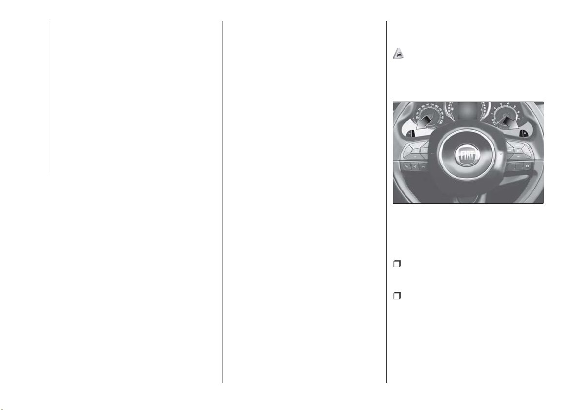
D can be selected from sequential
operation in any driving conditions.
“Kick-Down” function
To resume speed quickly, when the
accelerator pedal is pressed fully, the
transmission control system downshifts
(kick-down function).
IMPORTANT When driving on roads
with poor grip conditions (snow, ice,
etc.) avoid activating the kick-down
function.
Gearshifting suggestion
With the transmission in automatic
mode (selector lever in position D),
when gearshifting is required by the
paddles on the steering wheel (where
provided), the system shifts to
"Sequential mode" ("Autostick"),
displaying the engaged gear for about
5 seconds.
When this time has elapsed, if the
paddles are not operated anymore, the
system goes back to the automatic
mode (D), with following displaying.
AUTOSTICK - Sequential
mode
In the case of frequent gearshifting (e.g.
when the vehicle is driven with a heavy
load, on slopes, with strong headwind
or when towing heavy trailers), it is
recommended to use the Autostick
(sequential shifting) mode to select and
keep a lower fixed ratio.
In these conditions, using a lower gear
improves vehicle performance and
prolongs the transmission's life, limiting
gearshifting and preventing overheating.
It is possible to shift from position D
(Drive) to the sequential mode
regardless of vehicle speed.
Activation
With gear lever in position D (Drive), to
activate the sequential drive mode,
move the lever to the left (– and +
indication of the trim). The gear
engaged will be shown on the display.
Gearshifting is made by moving the
gear lever forwards, towards symbol –
or backwards, towards symbol +.
Deactivation
To deactivate the sequential driving
mode, bring the gear lever back to
position D (Drive), automatic mode.
STEERING WHEEL
CONTROLS
(where provided)
52)
On some versions, the gearbox can be
managed sequentially using the
steering wheel controls fig. 97.
To use the controls on the steering
wheel, the gear lever must be in
position D (Drive) between ( +) and ( –):
steering wheel paddle ( +) (pulling
paddle towards driver): engage higher
ratio;
steering wheel paddle ( -) (pulling
paddle towards driver): engage lower
ratio.
The engagement of a lower (or higher)
gear is only permitted if the engine revs
allow it.
97
F1B0508C
120
STARTING AND DRIVING
STARTING THE ENGINE
Starting the engine is allowed only
when the gear lever is in position P or
N. Therefore, when the engine is
started, the system will be at position N
or P (the latter means neutral, but with
the vehicle's wheels are locked
mechanically).
MOVING THE CAR
To move the car, from P press the brake
pedal and, using the button on the gear
lever, move the lever to the desired
position (D, R or "Sequential mode").
The display will show the gear engaged.
When the brake pedal is released, the
car starts moving forwards or
backwards, as soon as the manoeuvre
is activated ("creeping" effect). The
accelerator should not be pressed in
this case.
IMPORTANT The inconsistency
between the speed actually engaged
(shown on the display) and the position
of the gear lever is indicated by the
letter corresponding to the position of
the lever flashing on the trim (also
accompanied by an acoustic signal).
This condition should not be interpreted
as an operational fault, but simply as a
request by the system to repeat the
manoeuvre.
IMPORTANT With the electric parking
brake released and brake pedal
released, engine at idling speed and
gear lever in position D, R or sequential,
pay the utmost care because the car
can move even without the operation of
the accelerator pedal. This condition
can be used with the car on a level
surface during tight parking
manoeuvres using the brake pedal only.
GEAR ENGAGEMENT
INHIBITION
This system prevents you from moving
the gear lever from position P (Park) or
N (Neutral) if the brake pedal has not
been previously depressed.
When the ignition device is in MAR
(engine on or off):
to shift the gear to a position
different from P (Park) or from N to R,
you need to press the brake pedal and
the button A fig. 96 on the knob of the
gear lever;
to shift the lever from position N to
position D, press the brake pedal.
In case of a failure or when the vehicle's
battery is flat, the lever remains locked
in position P. To manually unlock the
lever, see paragraph "Automatic
transmission - lever unlocking" in the "In
an emergency" chapter.
VEHICLE SHUTDOWN
Versions equipped with the Keyless
Go system: this function requires the
gear lever to be positioned at P (Park);
then bring the ignition device to STOP.
Versions equipped with key without
remote control: this function requires
the gear lever to be positioned at P
(Park) before extracting the key from the
ignition device.
If the vehicle battery is flat and the
ignition key is engaged, the latter is
locked in position. To remove the key
manually see paragraph "Automatic
transmission - key removal" in the
chapter "In an emergency".
"RECOVERY" OPERATION
(where provided)
Transmission operation is constantly
monitored to detect any fault. If a
condition that might damage the
transmission is detected, the "recovery"
function is activated.
In this condition, the transmission stays
in 4
th
gear, regardless of the selected
gear.
Positions P (Parking), R (Reverse) and N
(Neutral) still work. Icon
might light
up in the display.
In the case of "recovery" operation
immediately contact the nearest Fiat
Dealership.
121
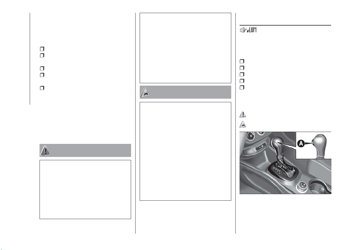
Temporary failure
In the event of a temporary failure,
correct transmission operation can be
restored for all the forwards gears by
proceeding as follows:
stop the vehicle;
bring the transmission lever to P
(Park).
bring the ignition device to STOP;
wait for about 10 seconds, then
restart the engine;
select the desired gear: correct
transmission operation should be
restored.
IMPORTANT In the event of a
temporary failure it is in any case
recommended to contact a Fiat
Dealership as soon as possible.
WARNING
114) Never use position P (Park) instead of
the electric parking brake. Always engage
the electric parking brake when parking the
vehicle to avoid the accidental movement
of the vehicle.
115) If the P (Park) position is not engaged,
the vehicle could move and injure people.
Before leaving the vehicle, make sure that
the gear lever is in position P and that the
electric parking brake is engaged.
116) Do not shift the gear lever to N
(Neutral) and do not stop the engine when
driving on a downhill road. This type of
driving is dangerous and reduces the
possibility of intervening in the case of
variation of the road traffic or surface. You
risk losing control of your vehicle and
causing accidents.
117) Never leave children alone in an
unattended vehicle; make sure that when
you move away from the vehicle, you have
the key with you.
IMPORTANT
48) Before moving the gear lever from
position P (Park), bring the ignition device
to position MAR and press the brake pedal.
Otherwise, the gear lever may get
damaged.
49) Engage reverse only with the car
stationary, engine at idling speed and
accelerator fully released.
50) If the car is on a gradient, always
engage the electric parking brake BEFORE
placing the gear lever in P.
51) Engage reverse only with the car
stationary, engine at idling speed and
accelerator pedal fully released.
52) Using the paddles incorrectly (paddles
pushed towards the dashboard ) could
break them.
TWIN CLUTCH
TRANSMISSION
GEAR LEVER
The fig. 98 lever has the following
positions:
P = Park
R = Reverse
N = Neutral
D = Drive, (automatic forward speed)
"AutoStick": + shifting to higher
gear in sequential driving mode; –
shifting to lower gear in sequential
driving mode.
118) 119) 120) 121)
53) 54) 55)
The gear engaged is shown on the
display.
To select the "sequential" mode, shift
the lever from D (Drive) towards the left.
98
F1B0137C
122
STARTING AND DRIVING

The reachable positions are + (higher
gear) or - (lower gear). These positions
are unstable: the lever always returns to
central position.
The lever has a button A fig. 98, which
must be pressed to move the lever to P
or R.
Shifting from P to any other position of
the selector lever, with ignition key in
MAR-ON position, must be made
pressing the brake pedal and using the
button on A fig. 98.
To shift from R to P, it is necessary to
push button A fig. 98 when engine is at
idle speed.
To shift from position N to D or R, you
need to press the brake pedal. It is
advisable not to accelerate and to
make sure that the engine is stabilised
at idle speed.
Shifting from D to N is free, while
shifting from D to R or P can only be
made by the button A fig. 98.
AUTOMATIC DRIVING
MODE
To select the automatic driving mode,
you need to shift the gear lever to D
(Drive): the best ratio is selected by the
electronic transmission control unit
depending on vehicle speed, engine
load (accelerator pedal position) and
gradient of the road.
D can be selected from sequential
operation in any driving conditions.
“Kick-Down” function
To resume speed quickly, when the
accelerator pedal is pressed fully, the
transmission control system downshifts
(kick-down function).
IMPORTANT When driving on roads
with poor grip conditions (snow, ice,
etc.) avoid activating the kick-down
function.
Gearshifting suggestion
With the transmission in automatic
mode (selector lever in position D),
when gearshifting is required by the
paddles on the steering wheel (where
provided), the system shifts to
"Sequential mode" ("Autostick"),
displaying the engaged gear for about
5 seconds.
When this time has elapsed, if the
paddles are not operated anymore, the
system goes back to the automatic
mode (D), with following displaying.
AUTOSTICK - Sequential
mode
In the case of frequent gearshifting (e.g.
when the vehicle is driven with a heavy
load, on slopes, with strong headwind
or when towing heavy trailers), it is
recommended to use the Autostick
(sequential shifting) mode to select and
keep a lower fixed ratio.
In these conditions, using a lower gear
improves vehicle performance and
prolongs the transmission's life, limiting
gearshifting and preventing overheating.
It is possible to shift from position D
(Drive) to the sequential mode
regardless of vehicle speed.
Activation
With gear lever in position D (Drive), to
activate the sequential drive mode,
move the lever to the left (– and +
indication of the trim). The gear
engaged will be shown on the display.
Gearshifting is made by moving the
gear lever forwards, towards symbol –
or backwards, towards symbol +.
Off
To deactivate the sequential driving
mode, bring the gear lever back to
position D (Drive), automatic mode.
123
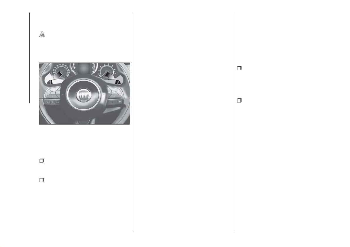
STEERING WHEEL
CONTROLS
(where provided)
56)
On some versions, the steering wheel
paddles fig. 99 can be used to change
gear.
To use the paddles on the steering
wheel, the gear lever must be in
"Sequential mode" or in D:
operating the steering wheel paddle (
+) (pulling the paddle towards the
driver): engage higher gear;
operating the steering wheel paddle (
−) (pulling the paddle towards the
driver): engage lower gear.
The engagement of a lower (or higher)
gear is only permitted if the engine revs
allow it.
STARTING THE ENGINE
Starting the engine is allowed only
when the gear lever is in position P or
N. Therefore, when the engine is
started, the system will be at position N
or P (the latter means neutral, but with
the vehicle's wheels are locked
mechanically).
MOVING THE CAR
To move the car, from P press the brake
pedal and, using the button on the gear
lever, move the lever to the desired
position (D, R or "Sequential mode").
The display will show the gear engaged.
When the brake pedal is released, the
car starts moving forwards or
backwards, as soon as the manoeuvre
is activated ("creeping" effect). The
accelerator should not be pressed in
this case.
IMPORTANT The inconsistency
between the speed actually engaged
(shown on the display) and the position
of the gear lever is indicated by the
letter corresponding to the position of
the lever flashing on the trim (also
accompanied by an acoustic signal).
This condition should not be interpreted
as an operational fault, but simply as a
request by the system to repeat the
manoeuvre.
GEAR ENGAGEMENT
INHIBITION
This system prevents you from moving
the gear lever from position P (Park) or
N (Neutral) if the brake pedal has not
been previously depressed.
When the ignition device is in MAR
(engine on or off):
to shift the gear to a position
different from P (Park) or from N to R,
you need to press the brake pedal and
the button A fig. 98 on the knob of the
gear lever;
to shift the lever from position N to
position D, press the brake pedal.
In case of a failure or when the vehicle's
battery is flat, the lever remains locked
in position P. To manually unlock the
lever, see paragraph "Twin clutch
automatic transmission - lever
unlocking" in the "In an emergency"
chapter.
VEHICLE SHUTDOWN
Versions equipped with the Keyless
Go system: this function requires the
gear lever to be positioned at P (Park);
then bring the ignition device to STOP.
Versions equipped with key without
remote control: this function requires
the gear lever to be positioned at P
(Park) before extracting the key from the
ignition device.
99
F1B0508C
124
STARTING AND DRIVING
If the vehicle battery is flat and the
ignition key is engaged, the latter is
locked in position. To remove the key
manually see paragraph "Twin clutch
automatic transmission - key removal"
in the chapter "In an emergency".
"RECOVERY"
FUNCTIONS
In case of a gear lever failure, the
instrument panel display could show a
dedicated message recommending that
the driver continues driving without
shifting the lever to the P position.
In this case, the transmission will
maintain the forward gear (with reduced
performance) even if the lever is
positioned at R or N.
Once the lever is positioned at P, or
after shutting down the vehicle,
selecting R or any other forward gear
will no longer be possible. In this case,
contact a Fiat Dealership.
WARNING
118) Never use position P (Park) instead of
the electric parking brake. Always engage
the electric parking brake when parking the
vehicle to avoid the accidental movement
of the vehicle.
119) If the P (Park) position is not engaged,
the vehicle could move and injure people.
Before leaving the vehicle, make sure that
the gear lever is in position P and that the
electric parking brake is engaged.
120) Do not shift the gear lever to N
(Neutral) and do not stop the engine when
driving on a downhill road. This type of
driving is dangerous and reduces the
possibility of intervening in the case of
variation of the road traffic or surface. You
risk losing control of your vehicle and
causing accidents.
121) Never leave children unattended in
the car. Always remove the ignition key
when leaving the car and take the key with
you.
IMPORTANT
53) Before moving the gear lever from
position P (Park), bring the ignition device
to position MAR and press the brake pedal.
Otherwise, the gear lever may get
damaged.
54) If the car is on a gradient, always
engage the electric parking brake BEFORE
placing the gear lever in P.
55) Engage reverse only with the car
stationary, engine at idling speed and
accelerator pedal fully released.
56) Using the paddles incorrectly (paddles
pushed towards the dashboard ) could
break them.
START&STOP
SYSTEM
The Start&Stop system automatically
stops the engine each time the vehicle
is stationary and starts it again when
the driver wants to move off.
In this way, the vehicle efficiency is
increased, by reducing consumption,
dangerous gas emissions and noise
pollution.
122)
57)
OPERATING MODE
Engine stopping mode
Versions with manual gearbox
With the vehicle stopped, the engine
stops with gearbox in neutral and clutch
pedal released.
Versions with automatic
transmission
With vehicle at a standstill and brake
pedal pressed, the engine switches off
if the gear lever is in a position other
than R.
In the event of stops uphill, engine
switching off is disabled to make the
"Hill Hold Control" function available
(works only with running engine).
125
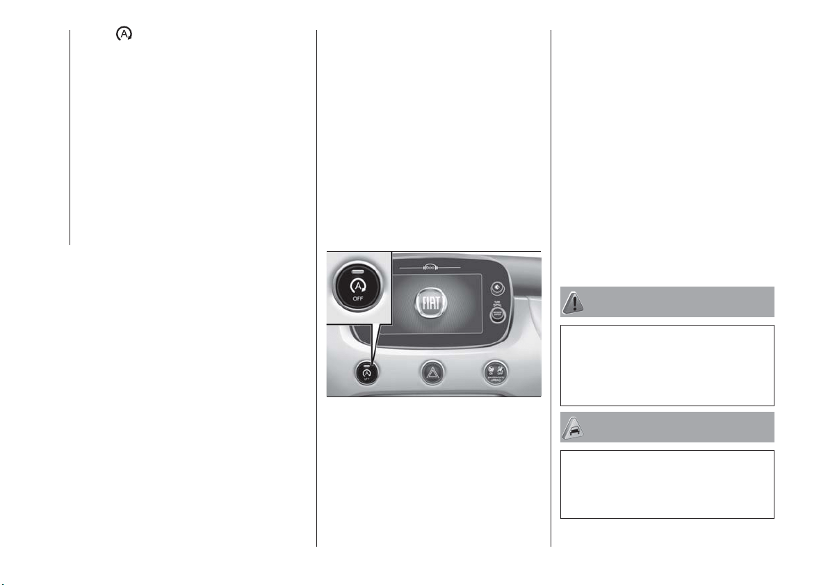
The warning light on the instrument
panel switches on to signal that the
engine was stopped.
Engine restarting mode
Versions with manual gearbox
To restart the engine, press the clutch
pedal. If the vehicle does not start when
the clutch is pressed, place the gear
lever in neutral and repeat the
procedure. If the problem persists,
contact a Fiat Dealership.
Versions with automatic
transmission
To restart the engine, release the brake
pedal.
With brake pressed, if the gear lever is
in automatic mode - D (Drive) - the
engine can be restarted by moving the
lever to R (Reverse) or N (Neutral) or
"AutoStick".
With brake pressed, if the gear lever is
in "AutoStick" mode, the engine can be
restarted moving the lever to "+" or "–",
or R (Reverse) or N (Neutral).
When the engine has been stopped
automatically, keeping the brake pedal
pressed, the brake can be released
keeping the engine off by quickly
shifting the gear lever to P (Park).
To restart the engine, just move the
lever out of position P.
SYSTEM MANUAL
ACTIVATION /
DEACTIVATION
To activate/deactivate the system
manually, press the fig. 100 button
located on the dashboard.
4x4 Versions: every time "Traction"
mode is set using Drive Mode (or Mood
Selector, depending on the market), the
Start&Stop system is deactivated. To
reactivate it, press the fig. 100 button
again. When exiting from the "Traction"
mode, the Stop/Start system returns to
the previously set status.
System activation
The system activation is indicated by a
message shown on the display. In this
case, the LED on the button fig. 100 is
off.
System deactivation
A message will appear on the display
when the system is deactivated. In this
condition, the LED on the
fig. 100 button is on.
SAFETY FUNCTIONS
When the engine is stopped through
the Start&Stop system, if the driver
releases their seat belt or opens the
driver's or passenger's door, the engine
can be restarted only by using the
ignition device.
This condition is indicated to the driver
both through a buzzer and a message
on the display.
WARNING
122) If the battery needs to be replaced,
always contact a Fiat Dealership. Replace
the battery with one of the same type
(HEAVY DUTY) and with the same
specifications.
IMPORTANT
57) If the climate comfort is to be favoured,
the Start&Stop system can be deactivated,
for a continuous operation of the climate
control system.
100
F1B0631C
126
STARTING AND DRIVING
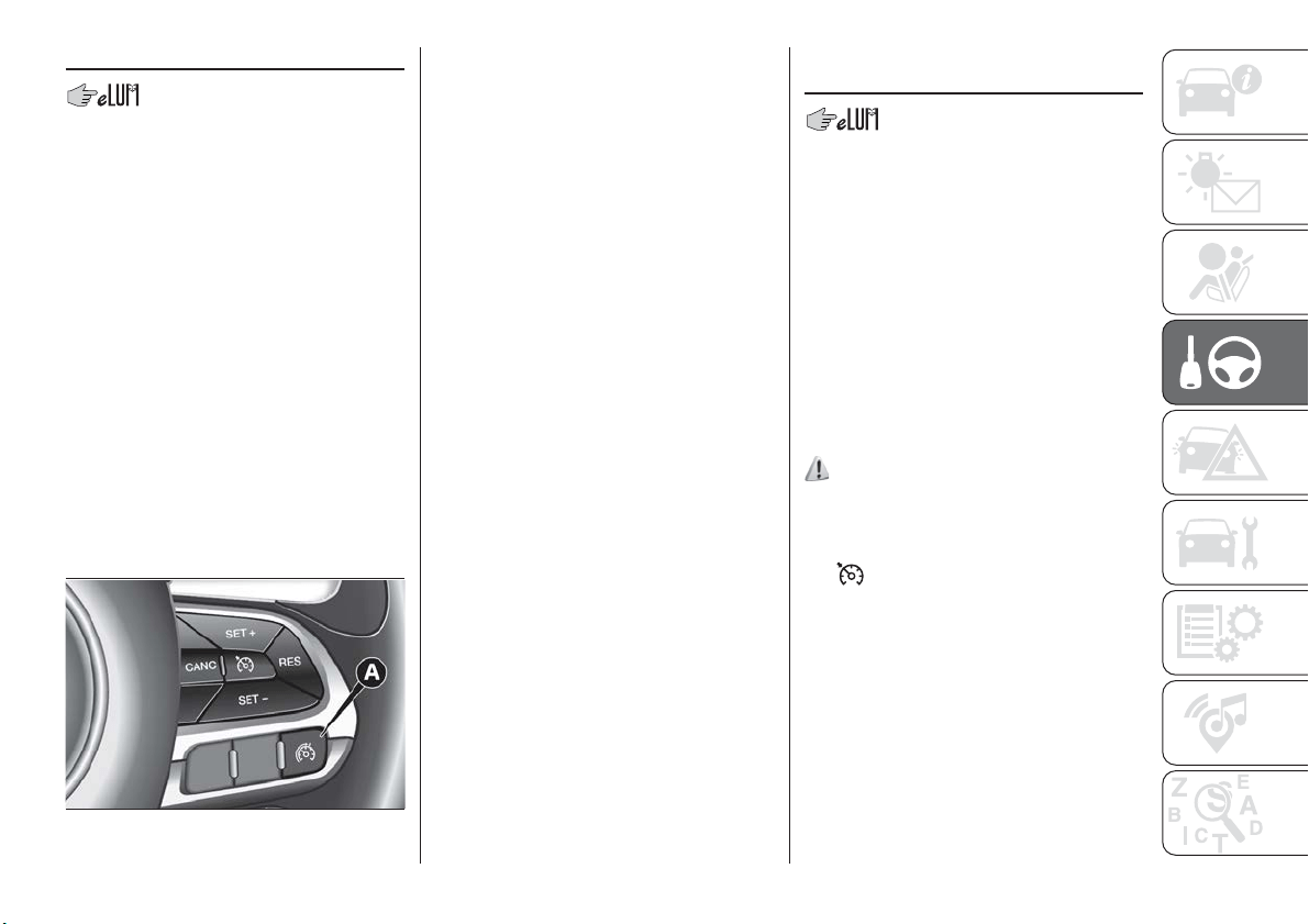
SPEED LIMITER
DESCRIPTION
This device allows the speed of the
vehicle to be limited to values which
can be set by the driver.
The maximum speed can be set both
with vehicle stationary and in motion.
The minimum speed that can be set is
30 km/h.
When the device is active, the vehicle
speed depends on the pressure at the
accelerator pedal, until the
programmed speed limit is reached
(see "Speed limit programming"
paragraph).
ACTIVATING THE DEVICE
To activate the device press button A
fig. 101 on the steering wheel.
AUTOMATIC
DEACTIVATION OF THE
DEVICE
The device deactivates automatically in
the event of fault in the system. In this
case, contact a Fiat Dealership.
ELECTRONIC
CRUISE CONTROL
This is an electronically controlled
driving assistance device that allows the
desired vehicle speed to be maintained,
without having to press the accelerator
pedal. This device can be used at a
speed above 30 km/h on long stretches
of dry, straight roads with few variations
(e.g. motorways).
It is therefore not recommended to use
this device on extra-urban roads with
traffic. Do not use it in town.
ACTIVATING THE DEVICE
123) 124) 125)
To activate the device press button A
fig. 102.
Activation of the device is indicated by
the
symbol on the display switching
on and, on some versions, by a
dedicated message.
If the Speed Limiter is activated, button
Afig. 102 must be pressed twice to
activate the Cruise Control.
101
F1B0141C
127
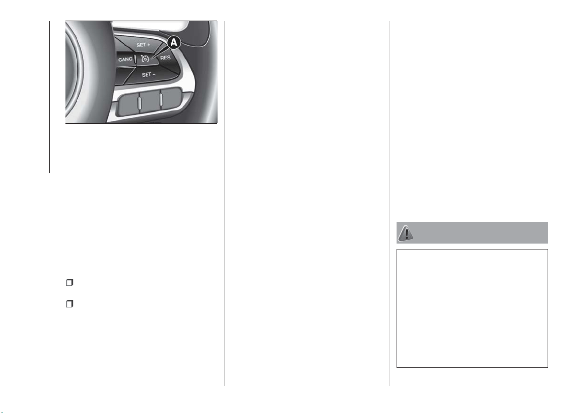
The device cannot be engaged in 1
st
or reverse gear: it is advisable to
engage it in 3
rd
gear or higher.
IMPORTANT It is dangerous to leave
the device on when it is not used. There
is a risk of inadvertently activating it and
losing control of the vehicle due to
unexpected excessive speed.
SETTING THE DESIRED
SPEED
Proceed as follows:
to activate the device press button A
fig. 102;
when the vehicle has reached the
desired speed, press button SET + (or
SET –) and release it to activate the
device. When the accelerator is
released, the vehicle will keep the
selected speed automatically.
If needed (e.g. when overtaking), you
can increase speed simply by pressing
the accelerator; when you release the
pedal, the vehicle goes back to the
speed stored previously.
When travelling downhill with the device
active, the vehicle speed may slightly
exceed the set one.
IMPORTANT Before pressing the SET +
or SET – buttons, the vehicle must be
travelling at a constant speed on a flat
surface.
SPEED INCREASE
Once the electronic Cruise Control has
been activated, the speed can be
increased by pressing button SET +.
SPEED DECREASE
With the device activated, the speed
can be decreased by pressing button
SET–.
RECALLING THE SPEED
For versions with automatic
transmission operating in D mode (Drive
- automatic), press and release the RES
button to recall the previously set
speed.
For versions with manual gearbox or
automatic transmission in Autostick
(sequential) mode, before recalling the
previously set speed you should
accelerate until getting close to it, then
press and release the RES button.
DEACTIVATING THE
DEVICE
Lightly pressing the brake pedal or
pressing the CANC button deactivates
the electronic Cruise Control without
deleting the stored speed.
The Cruise Control may be deactivated
also by applying the electric parking
brake (EPB) or when the braking
system is operated (e.g. operation of
the ESC system).
DEACTIVATING THE
DEVICE
The electronic Cruise Control is
deactivated by pressing button A
fig. 102 or bringing the ignition device
to STOP.
WARNING
123) When travelling with the device active,
never move the gear lever to neutral.
124) In case of a malfunction or failure of
the device, contact a Fiat Dealership.
125) The electronic Cruise Control can be
dangerous if the system cannot keep a
constant speed. In specific conditions
speed may be excessive, resulting in the
risk of losing control of the vehicle and
causing accidents. Do not use the device
in heavy traffic or on winding, icy, snowy or
slippery roads.
102
F1B0140C
128
STARTING AND DRIVING
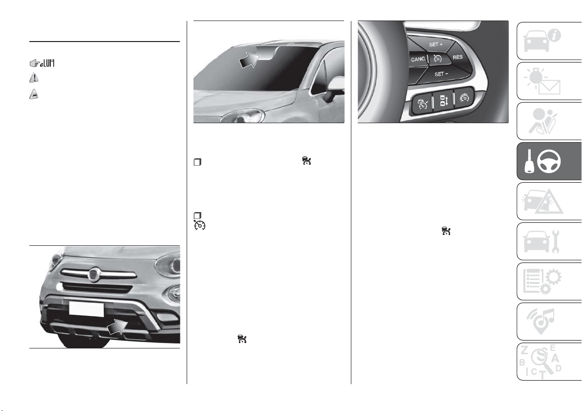
ADAPTIVE CRUISE
CONTROL (ACC)
(where provided)
126) 127) 128) 129) 130) 131)
58) 59) 60) 61) 62) 63) 64)
DESCRIPTION
The Adaptive Cruise Control (ACC) is a
driver assist device which combines the
Cruise Control functions with one for
controlling the distance from the vehicle
ahead.
The Adaptive Cruise Control (ACC) uses
a radar sensor, located behind the front
bumper fig. 103 and a camera, located
in the middle of the windscreen fig. 104,
to detect the presence of a vehicle
close ahead.
There are two operating modes:
“Adaptive Cruise Control” mode
to maintain an adequate distance
between vehicles (the message
“Adaptive Cruise Control” is shown on
the instrument panel display);
electronic “Cruise Control” mode
to hold the vehicle at a constant
preset speed.
To change the operating mode, use the
button on the steering wheel (see that
described on the following pages).
ADAPTIVE CRUISE
CONTROL ACTIVATION/
DEACTIVATION
Activation
To activate the device, press and
release the
button (see figure).
IMPORTANT It is dangerous to leave
the device activated when it is not
used. There is a risk of inadvertently
activating it and losing control of the car
due to unexpected excessive speed.
Deactivation
With the device active, to deactivate it
press and release the
button. The
display will show a dedicated message.
SETTING THE DESIRED
SPEED
The device can only be set when the
speed is over 30 km/h (or equivalent
in mph) and under 160 km/h (or
equivalent in mph).
When the vehicle reaches the desired
speed, press and release the button
SET + or SET to set the speed to the
current speed. The display will show the
set speed. Then take your foot off the
accelerator pedal.
103
F1B0095C
104
F1B0096C
105
J0A0917C
129

When the system has been set, the
dedicated icon on the display (see
paragraph above) is grey on models
with a monochrome display, and green
on versions with a colour display.
IMPORTANT Press the accelerator
pedal to make the car go faster than
the set speed.
While the accelerator pedal is pressed:
a dedicated message is displayed for
a few seconds;
the device will not be able to control
the distance between the vehicle and
the one ahead. In this case the speed
will be determined only by the position
of the accelerator pedal.
The device will return to normal
operation as soon as the accelerator
pedal is released.
The system cannot be set
when pressing the brake pedal;
when the brakes are overheated;
when the electric parking brake is
engaged;
when the shift lever is in the P (park),
R (reverse) or N (neutral) positions
(versions with automatic transmission or
automatic transmission with double
clutch);
when the shift lever is in the R
(reverse), neutral or in 1
st
(first gear
engaged) positions (versions with
manual transmission);
when the clutch is pressed (versions
with manual transmission);
when the engine speed exceeds a
maximum threshold (versions with
manual transmission and versions with
automatic transmission/automatic
transmission with double clutch) or
goes below a minimum threshold (only
versions with manual transmission);
when the car speed is not within the
settable speed range;
when the ESC (or ABS or other
stability control systems) are operating
or have just operated;
when the ESC system is off;
during automatic braking by the Full
Brake Control system (where provided);
when the Speed Limiter is active;
when the electronic Cruise Control is
active;
in case of failure of the device;
when the engine is off;
in case of obstruction of the radar
sensor (in this case the bumper area
where it is located must be cleaned).
In case of system set, the conditions
described above also cause a
cancellation or deactivation of the
system with times that may vary
according to the conditions.
IMPORTANT With the device set, it is
possible to reach speeds higher than
those set in the system by pressing the
accelerator pedal. In this condition, the
device does not turn off automatically,
but the device functions are limited: it is
therefore recommended to turn it off.
CHANGING SPEED
Speed increase
After having set the device, the stored
speed can be stored by holding the
SET + button pressed.
Press the SET + button once: the set
speed will increase by 1 km/h (or the
equivalent in mph). Each touch of the
button once will increase the speed by
1 km/h (or the equivalent in mph).
Hold the SET + button down: the set
speed will increase in 10 km/h steps (or
the equivalent in mph) until the button is
released. The set speed increase is
shown on the display.
Decreasing speed
After having set the device, the stored
speed can be reduced by holding the
SET – button pressed.
Press the SET – button once: the set
speed will decrease by 1 km/h (or the
equivalent in mph). Each touch of the
button once will reduce the speed by
1 km/h (or the equivalent in mph).
130
STARTING AND DRIVING
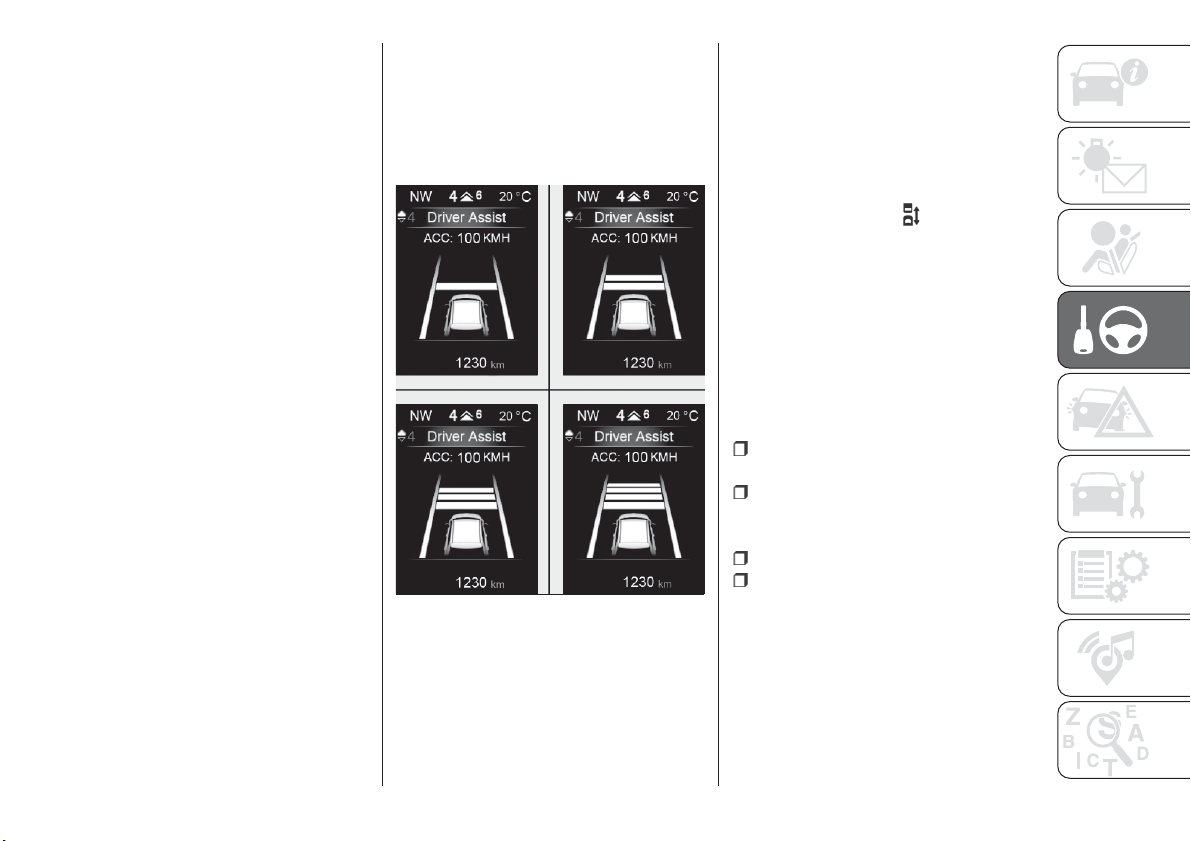
Hold the SET – button down: the set
speed will decrease in 10 km/h steps
(or the equivalent in mph) until the
button is released. The set speed
decrease is shown on the display.
NOTE If you select “Sport” mode in
Drive Mode (or Mood Selector,
depending on the market), the ACC will
switch to sport mode: the system will
become more reactive when
accelerating.
ACCELERATING WHEN
OVERTAKING
When driving with the device active and
following a vehicle, the device provides
additional acceleration to facilitate
overtaking, when travelling over a given
speed and switches on the left direction
indicator (of the right indicator for
right-hand drive versions).
RECALLING THE SPEED
Once the system has been cancelled
but not deactivated, if a speed was
previously set simply press the RES
button and remove your foot from the
accelerator to recall it.
The system will be set to the last stored
speed.
Before returning to the previously set
speed, bring the speed close to that
value, then press the RES button and
release it.
SETTING THE DISTANCE
BETWEEN CARS
The distance between your vehicle and
the vehicle ahead may be set to 1 bar
(short), 2 bars (medium), 3 bars (long),
4 bars (maximum) fig. 106.
The distances from the vehicle ahead
are proportional to speed. The interval
of time with respect to the vehicle
ahead remains constant and varies
from 1 second (for the short distance
1-bar setting) to 2 seconds (for the
maximum distance 4-bar setting).
The setting is 4 (maximum) the first time
the device is used. After the distance
has been modified by the driver, the
new distance will be stored also after
the system is deactivated and
reactivated.
To decrease the distance
Press and release the
button to
decrease the distance setting.
The distance setting decreases by one
bar (shorter) every time the button is
pressed.
The set speed is held if there are no
cars ahead. Once the shortest distance
has been reached, a further press of
the button will set the longest distance.
The car holds the set distance until:
the vehicle ahead accelerates to a
speed higher than the set speed;
the vehicle ahead leaves the lane or
the detection field of the Adaptive
Cruise Control device sensor;
the distance setting is changed;
the Adaptive Cruise Control device is
deactivated/cancelled.
IMPORTANT The maximum breaking
applied by the device is limited. The
driver may apply the brakes in all cases
if needed.
106
F1B0299C
131
IMPORTANT If the device predicts that
the braking level is not sufficient to hold
the set distance, the driver is warned by
a message indicating that the vehicle
ahead is too close appears on the
display. An acoustic warning is also
emitted. In this case, it is advisable to
brake immediately as necessary to hold
a safe distance from the vehicle ahead.
IMPORTANT The driver is responsible
for ensuring that there are no
pedestrians, other cars or objectives
along the direction of the car. Failure to
comply with these precautions may
cause serious accidents and injuries.
IMPORTANT The driver is fully
responsible for holding a safe distance
from the vehicle ahead respecting the
highway code in force in the respective
country.
DEACTIVATION
The device is deactivated and the set
speed is cancelled if:
the button is pressed on the
Adaptive Cruise Control;
the button is pressed on the
electronic Cruise Control;
the Speed Limiter button is pressed;
the ignition device is in the STOP
position.
The device is cancelled (the set speed
and distance are stored):
when the CANC button is pressed;
when the conditions shown in the
“Setting the desired speed” paragraph
occur;
when the car speed drops under the
minimum set speed (e.g. in presence of
slow cars).
If these conditions occur while the
system is decelerating with respect to a
vehicle ahead, the system could
continue the deceleration, if necessary,
also after it is cancelled or deactivated
within the minimum speed settable on
the system.
ELECTRONIC CRUISE
CONTROL MODE
Electronic Cruise Control mode is
available for travelling at constant speed
in addition to the Adaptive Cruise
Control (ACC) mode.
If the Adaptive Cruise Control (ACC)
function is implemented on the vehicle,
the electronic Cruise Control works in
the same manner as the ACC (by
pressing the
button of the Cruise
Control) with the difference that:
it does not hold the distance from the
vehicle ahead;
the device keeps working if the radar
sensor is obstructed.
Before returning to the previously set
speed, bring the speed close to that
value, then press the RES button and
release it.
WARNING
126) Pay the utmost attention while driving
at all times and be always ready to press
the brakes if needed.
127) The system is an aid for the driver,
who must always pay full attention while
driving. The responsibility always rests with
the driver, who must take into account the
traffic conditions in order to drive in
complete safety. The driver must always
maintain a safe distance from the vehicle in
front.
128) The device is not activated in
presence of pedestrians, oncoming
vehicles in the opposite direction of travel
or moving in the crosswise direction and
stationary objects (e.g. a vehicle standing
in a queue or a broken down vehicle).
129) The device cannot take account of
road, traffic and weather conditions, and
conditions of poor visibility (e.g. fog).
130) The device does not always fully
recognise complex driving conditions that
could cause it to determine the safe
distance to be held incorrectly or not at all.
131) The device cannot apply the
maximum braking force: the car will not be
stopped completely.
IMPORTANT
58) The system may have limited or absent
operation due to weather conditions such
as: heavy rain, hail, thick fog, heavy snow.
132
STARTING AND DRIVING
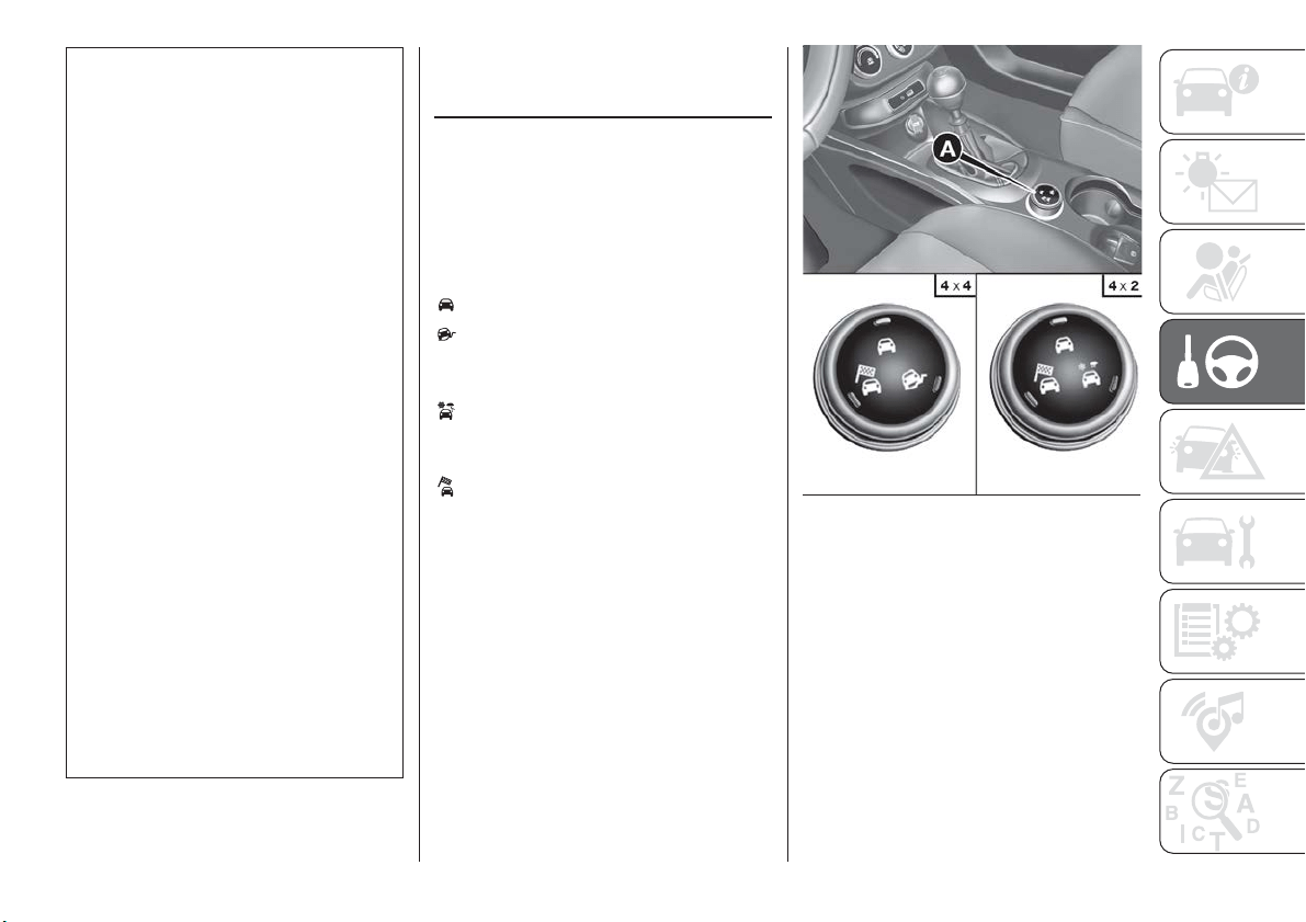
59) The section of the bumper before the
sensor must not be covered with
adhesives, auxiliary headlights or any other
object.
60) Operation can be adversely affected by
any structural change made to the vehicle,
such as a modification to the front
geometry, tyre change, or a heavier load
than the standard load of the vehicle.
61) Incorrect repairs made on the front part
of the car (e.g. bumper, chassis) may alter
the position of the radar sensor, and
adversely affect its operation. Go to a Fiat
Dealership for any operation of this type.
62) Do not tamper with or carry out any
intervention on the radar sensor or on the
camera on the windscreen. In the event of
a sensor fault, contact a Fiat Dealership.
63) Do not wash with high-pressure jets in
the bumper lower area: in particular do not
operate on the system's electrical
connector.
64) Be careful in the case of repairs and
new paintings in the area around the
sensor (panel covering the sensor on the
left side of the bumper). In the event of a
frontal impact the sensor may automatically
deactivate and display a warning to indicate
that the sensor needs to be repaired. Even
without a malfunction warning, deactivate
the system operation if you think that the
position of the radar sensor has changed
(e.g. due to low-speed frontal impact as
during parking manoeuvres). In these
cases, go to a Fiat Dealership to have the
radar sensor realigned or replaced.
MOOD SELECTOR /
DRIVE MODE (drive
mode selector)
(where provided)
This device allows drivers to select
three different driving modes ("car
response") according to their needs and
to the road and traffic conditions, by
manually adjusting the knob ring A
fig. 107 on the central tunnel.
- "Auto" mode
- "Traction" mode (4x4 or
4x2 versions depending on the trim
level)
- "All Weather" mode (only
4x2 versions depending on the trim
level)
- "Sport" mode.
The device, through the on-board
electronic system, operates on the
dynamic control systems of the car:
engine, steering, ESC system,
4x4 system (if available),
gearbox/transmission, and is interfaced
with the instrument panel.
The rotating ring nut is monostable
type. In other words, it always returns
to the central position when released.
107
F1B0044C
133

The acceptance by the system of the
requested driving mode is signalled by
the LED, located besides the symbol,
coming on, and by the corresponding
symbol appearing on the instrument
panel display.
When the engine is started, the system
usually maintains the driving mode that
was active before the engine was
stopped. For versions/markets where
provided, on start-up, the system is set
to the "Auto" mode.
"Auto" MODE
Recommended mode for normal
driving, aimed at comfort and safety in
normal grip and driving conditions. On
4x4 versions, this mode also reduces
fuel consumption, since it automatically
disconnects the transmission from the
rear wheels if the road and driving
conditions allow it, in addition to
changing drive torque distribution
between the front and rear axles.
Activation
Starting from the active "Traction/All
Weather" mode, turn the ring nut
anticlockwise, keeping it in this position
for at least half a second, and in any
case until the relevant LED turns on,
and the selected mode is shown on the
display. The LED for the previously set
mode will simultaneously turn off.
Upon release, the ring nut will return to
the central position.
Starting from the active "Sport" mode,
turn the ring nut clockwise, keeping it in
this position for at least half a second,
and in any case until the relevant LED
turns on, and the selected mode is
shown on the display. The LED for the
previously set mode will simultaneously
turn off. Upon release, the ring nut will
return to the central position.
"Traction"/"All Weather"
MODE
It is a driving mode for safety in poor
vehicle grip conditions (wet/slippery
road surface, rain, snow). On the
4x4 versions use is also recommended
on unsurfaced roads or off-road.
Activation
Starting from the active "Auto" mode,
turn the ring nut clockwise, keeping it in
this position for at least half a second,
and in any case until the relevant LED
turns on, and the selected mode is
shown on the display. The LED for the
previously set mode will simultaneously
turn off. Upon release, the ring nut will
return to the central position.
Starting from the active "Sport" mode,
turn the ring nut anticlockwise, keeping
it in this position for at least half a
second, and in any case until the
relevant LED turns on, and the selected
mode is shown on the display. The LED
for the previously set mode will
simultaneously turn off. Upon release,
the ring nut will return to the central
position.
"Sport" MODE
It is the mode that emphasises the
pleasure of sport driving; it increases
fuel consumption however. Traction is
optimised on 4x4 versions, allowing the
vehicle road-hold performance to be
improved, even on bends.
Activation
Starting from the active "Auto" mode,
turn the ring nut anticlockwise, keeping
it in this position for at least half a
second, and in any case until the
relevant LED turns on, and the selected
mode is shown on the display. The LED
for the previously set mode will
simultaneously turn off. Upon release,
the ring nut will return to the central
position.
134
STARTING AND DRIVING
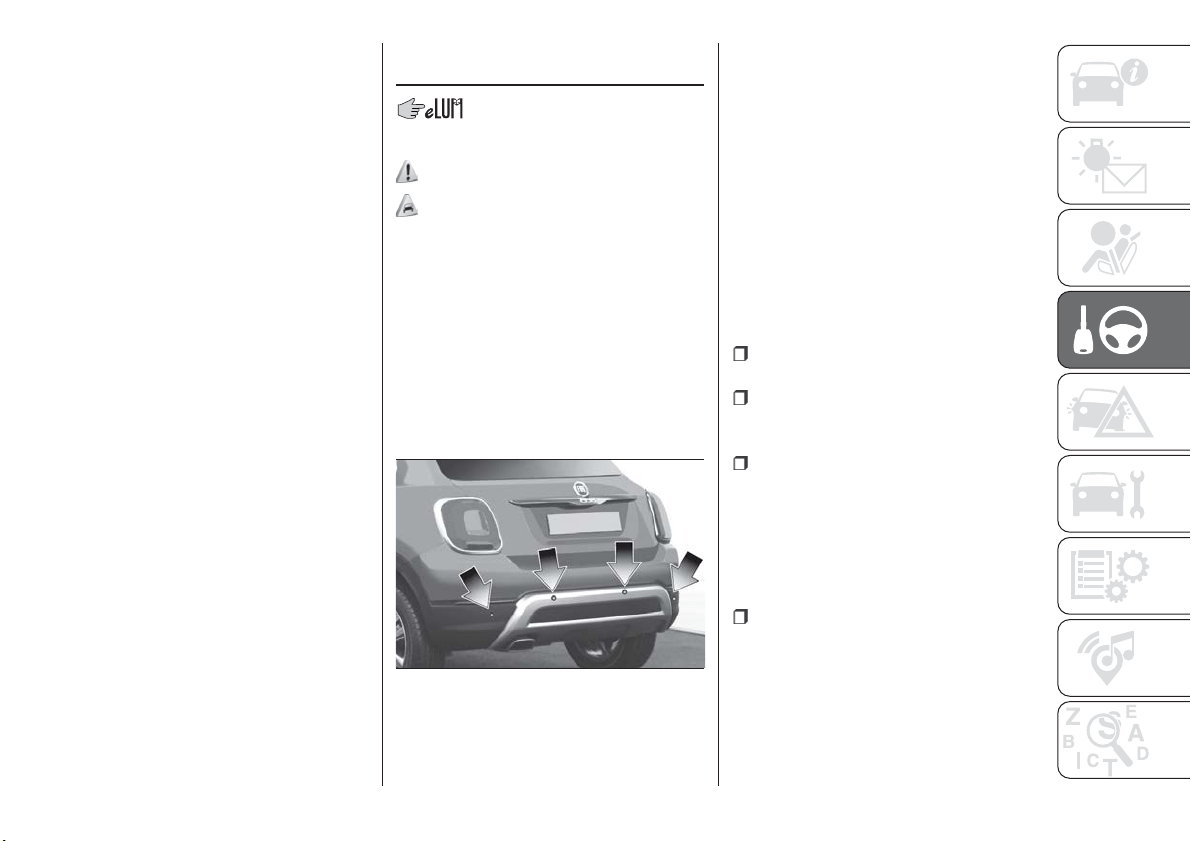
Starting from the active "Traction/All
Weather" mode, turn the ring nut
clockwise, keeping it in this position for
at least half a second, and in any case
until the relevant LED turns on, and the
selected mode is shown on the display.
The LED for the previously set mode will
simultaneously turn off. Upon release,
the ring nut will return to the central
position.
FAULT INDICATIONS
In the case of system and selector
faults, the mode change option will be
automatically disabled. The system will
automatically set itself to "Auto" mode.
In these cases the display will show a
dedicated warning. Go to a Fiat
Dealership as soon as possible to have
the system checked.
PARK ASSIST
SYSTEM
SENSORS
132)
65) 66) 67)
The parking sensors, located in the rear
bumper fig. 108, are used to detect the
presence of any obstacles near the rear
part of the vehicle.
The sensors warn the driver about the
presence of possible obstacles with an
intermittent acoustic signal and,
depending on the version, also with
visual indications on the instrument
panel display.
Activation
The sensors are automatically activated
when reverse gear is selected. As the
distance from the obstacle behind the
vehicle decreases, the frequency of the
acoustic signal increases.
Acoustic signal
When reverse is engaged and there is
an obstacle behind the vehicle, an
acoustic signal is activated and the
signal varies as the distance of the
obstacle from the bumper varies.
The frequency of the acoustic signal:
increases as the distance between
the vehicle and the obstacle decreases;
becomes continuous when the
distance separating the vehicle from the
obstacle is less than about 30 cm;
is constant if the distance between
the vehicle and the obstacle is
unchanged. If this situation concerns
the side sensors, the signal will stop
after approximately 3 seconds to avoid,
for example, indications in the event of
manoeuvres along a wall.
stops immediately if the distance of
the obstacle increases.
When the system emits the acoustic
signal, the volume of the Uconnect™
system is automatically lowered.
108
F1B0142C
135

Detection distances
If several obstacles are detected by the
sensors, only the nearest one is
considered.
Indication on display
The indications regarding the Park
Assist system are shown on the
instrument panel display only if the
"Acoustic signal and display" item in the
"Settings" menu of the Uconnect™
system is selected (for more
information, see the description in the
dedicated chapter).
The system indicates the presence of
an obstacle by displaying a single arc in
one of the possible areas, in
accordance with the distance of the
object and the position in relation to the
vehicle. If the obstacle is detected in the
rear central area, a single arc will be
displayed as the obstacle approaches,
first constant, then flashing, in addition
to an acoustic signal.
OPERATION WITH
TRAILER
68)
The operation of the sensors is
automatically deactivated when the
trailer's electrical connection is inserted
in the vehicle's tow hook socket.
Sensors are reactivated on removing
the trailer's electrical connection.
Before using the Park Assist system, it
is recommended to remove the tow
hook ball assembly and the relevant
attachment from the vehicle. Failure to
comply with this prescription may
cause personal injuries or damage to
vehicles or obstacles since, when the
continuous acoustic signal is emitted,
the tow hook ball is already in a position
that is much closer to the obstacle than
the rear bumper.
GENERAL WARNINGS
Some conditions may influence the
performance of the parking system:
reduced sensor sensitivity and a
reduction in the parking assistance
system performance could be due to
the presence of: ice, snow, mud, paint,
etc. on the surface of the sensor;
the sensor may detect a
non-existent obstacle ("echo
interference") due to mechanical
interference, for example when washing
the vehicle, in rain (strong wind), hail;
the signals sent by the sensor can
also be altered by the presence of
ultrasonic systems (e.g. pneumatic
brake systems of trucks or pneumatic
drills) near the vehicle;
Parking assistance system
performance can also be influenced by
the position of the sensors, for example
due to a change in the ride setting
(caused by wear to the shock
absorbers, suspension), or by changing
tyres, overloading the vehicle or fitting
specific trims that require the vehicle to
be lowered;
the presence of a tow hook without
trailer, which may interfere with the
correct operation of the parking
sensors. If you wish to leave the tow
hook fitted without towing a trailer, it is
advisable to contact a Fiat Dealership
for the relevant Park Assist system
update operations because the tow
hook could be detected as an obstacle
by the central sensors.
the presence of adhesives on the
sensors. Therefore, take care not to
place adhesives on the sensors.
136
STARTING AND DRIVING
WARNING
132) Parking and other potentially
dangerous manoeuvres are, however,
always the driver’s responsibility. When
performing these operations, always make
sure that there are no other people
(especially children) or animals on the route
you want to take. The parking sensors are
an aid for the driver, but the driver must
never allow their attention to lapse during
potentially dangerous manoeuvres, even
those executed at low speeds.
IMPORTANT
65) The sensors must be clean of mud,
dirt, snow or ice in order for the system to
operate correctly. Be careful not to scratch
or damage the sensors while cleaning
them. Avoid using dry, rough or hard
cloths. The sensors should be washed
using clean water with the addition of car
shampoo if necessary. When using special
washing equipment such as high pressure
jets or steam cleaning, clean the sensors
very quickly keeping the jet more than
10 cm away.
66) Have interventions on the bumper in
the area of the sensors carried out only by
a Fiat Dealership. Interventions on the
bumper that are not carried out properly
may compromise the operation of the
parking sensors.
67) Only have the bumpers repainted or
any retouches to the paintwork in the area
of the sensors carried out by a Fiat
Dealership. Incorrect paint application
could affect the operation of the parking
sensors.
68) The sensors may provide a false
indication, interpreting the tow hook ball
assembly and the relevant attachment as
an obstacle in the area behind the vehicle.
LANE ASSIST
SYSTEM (lane
crossing warning)
DESCRIPTION
69) 70) 71) 72) 73) 74)
The Lane Assist system makes use of a
camera located on the windscreen to
detect the lane limits and calculate the
position of the vehicle within such limits,
in order to make sure that it remains
inside the lane.
When both limits of the lane are
detected and the vehicle crosses one of
them without the awareness of the
driver (direction indicator off), the Lane
Assist system provides a tactile warning
by applying torque to the steering wheel
(vibration), thus advising the driver that
he must take an action to remain in the
lane.
IMPORTANT The torque applied to the
steering wheel by the system is
sufficient for the driver to notice it, but
always limited, so that they can easily
override it, and the driver always
maintains control of the vehicle. The
driver can therefore turn the steering
wheel as required at all times.
137
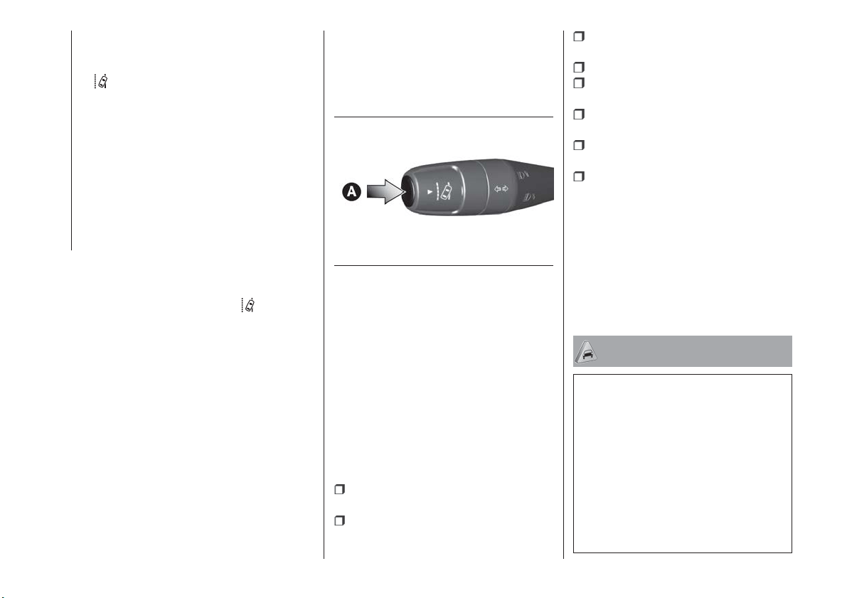
If the vehicle continues going beyond
the line of the lane without any
intervention from the driver, the
warning light (or the icon on the
display) will be displayed on the
instrument panel to urge the driver to
bring the vehicle back into the limits of
the lane.
IMPORTANT The system monitors the
presence of the driver's hands on the
steering wheel. If they are not detected,
the system emits an acoustic signal and
deactivates until it is reactivated by
pressing the dedicated button (see
description below).
When one limit of the lane is detected
and the vehicle crosses it (direction
indicator off), warning light
(or the
icon on the display) will be displayed on
the instrument panel to urge the driver
to bring the vehicle back into the lane.
In this case, the tactile warning
(vibration on the steering wheel) is not
provided.
SYSTEM ACT_IVATION/
DEACTIVATION
The Lane Assist system can be
enabled/disabled using button A
fig. 109, located on the left stalk.
Each time the engine is started, the
system keeps the activation status
there was when it was previously
switched off.
On some versions, a dedicated
message appears on the display when
it is activated and deactivated.
Activation conditions
Once switched on, the system
becomes active only if the following
conditions are met:
the driver always keeps at least one
hand on the steering wheel;
vehicle speed ranges between
60 km/h and 180 km/h;
the lane limit lines are perfectly visible
on both sides;
there are suitable visibility conditions;
the road is straight or with wide
radius bends;
a suitable distance is kept from the
vehicle in front;
the direction indicator (for leaving the
lane) is not active;
the lane limit lines are perfectly
visible on both sides (for activation of
the tactile warning only).
NOTE The system does not apply the
vibration to the steering wheel every
time a safety system is activated
(brakes, ABS, ASR system, ESC
system, Full Brake Control system,
etc.).
IMPORTANT
69) Projecting loads on the roof of the
vehicle may interfere with the correct
operation of the camera. Before starting
make sure the load is correctly positioned,
in order not to cover the camera operating
range.
70) If the windscreen must be replaced due
to scratches, chipping or breakage, contact
exclusively a Fiat Dealership. Do not
replace the windscreen on your own, risk of
malfunction! It is advisable to replace the
windscreen if it is damaged in the area of
the camera.
109
F1B0334C
138
STARTING AND DRIVING
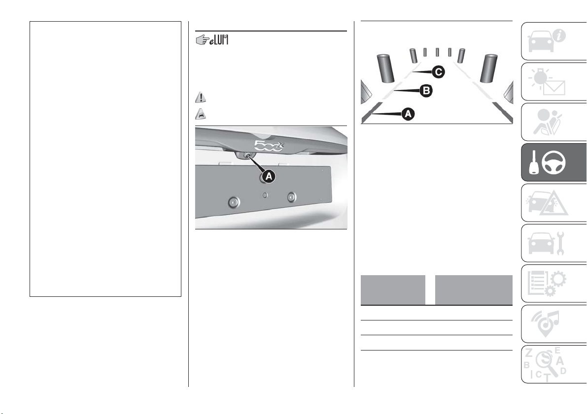
71) Do not tamper with nor operate on the
camera. Do not close the openings in the
aesthetic cover located under the interior
rear view mirror. In the event of a failure of
the camera, contact a Fiat Dealership.
72) Do not cover the operating range of the
camera with stickers or other objects. Also
pay attention to other objects on the
bonnet (e.g. a layer of snow) and make
sure they do not interfere with the camera.
73) The camera may have limited or absent
operation due to weather conditions such
as: heavy rain, hail, thick fog, heavy snow,
formation of ice layers on the windscreen.
74) Camera operation may also be
compromised by the presence of dust,
condensation, dirt or ice on the
windscreen, by traffic conditions (e.g.
vehicles that are driving not aligned with
yours, vehicle driving in a transverse or
opposite way on the same lane, bend with
a small radius of curvature), by road
surface conditions and by driving
conditions (e.g. off-road driving). Make sure
the windscreen is always clean. Use
specific detergents and clean cloths to
avoid scratching the windscreen. The
camera operation may also be limited or
absent in some driving, traffic and road
surface conditions.
REAR VIEW CAMERA
DESCRIPTION
The camera A fig. 110 is located on the
tailgate.
133)
75)
Every time reverse is engaged, the
display fig. 111 shows the area around
the vehicle, as seen by the rear camera.
SYMBOLS AND
MESSAGES ON THE
DISPLAY
A superimposed central broken line
indicates the centre of the vehicle to
facilitate parking manoeuvres or tow
hook alignment. The various coloured
areas indicate the distance from the
rear of the vehicle.
The table below shows the approximate
distances for each area fig. 111:
Area
Distance from the
rear of the vehicle
Red (A) 0–30 cm
Y
ellow (B) 30–100 cm
Green (C) 1 m or more
IMPORTANT When parking, take the
utmost care over obstacles that may be
above or under the camera range.
110
F1B0064C
111
F1B0167C
139
WARNING
133) Parking and other potentially
dangerous manoeuvres are, however,
always the driver’s responsibility. While
carrying out these manoeuvres, always
make sure that no people (especially
children) or animals are in the area
concerned. The camera is an aid for the
driver, but the driver must never allow
his/her attention to lapse during potentially
dangerous manoeuvres, even those
executed at low speeds. Always keep a
slow speed, so as to promptly brake in the
case of obstacles.
IMPORTANT
75) It is vital, for correct operation, that the
camera is always kept clean and free from
any mud, dirt, snow or ice. Be careful not
to scratch or damage the camera while
cleaning it. Avoid using dry, rough or hard
cloths. The camera must be washed using
clean water, with the addition of car
shampoo if necessary. In washing stations
which use steam or high-pressure jets,
clean the camera quickly, keeping the
nozzle more than 10 cm away from the
sensors. Also, do not apply stickers to the
camera.
TOWING TRAILERS
IMPORTANT
134) 135)
For towing caravans or trailers the
vehicle must be fitted with an approved
tow hook and an adequate electrical
system. Should aftermarket installation
be requested, this must be carried out
by specialists.
Install any specific and/or additional
door mirrors as specified by the
Highway Code.
Remember that when towing a trailer,
steep hills are harder to climb, braking
distances increase and overtaking takes
longer depending on the overall weight
of the trailer. Engage a low gear when
driving downhill, rather than constantly
using the brake. The weight the trailer
exerts on the vehicle tow hook reduces
the vehicle's loading capacity by the
same amount. To make sure that the
maximum towable weight is not
exceeded (given in the vehicle
registration document) account should
be taken of the fully laden trailer,
including accessories and luggage.
Do not exceed the speed limits specific
to each country you are driving in, in the
case of vehicles towing trailers. In any
case, the top speed must not exceed
100 km/h.
Any electric brake must be powered
directly by the battery through a cable
with a cross-section of no less than
2.5 mm
2
. In addition to the electrical
branches, the vehicle electrical system
can only be connected to the supply
cable for an electric brake and to the
cable for an internal light for the trailer,
not exceeding 15 W. For connections,
use the preset control unit with a
battery cable with section not less than
2.5 mm
2
. The use of auxiliary loads
other than external lights (e.g. electric
brake) must take place with engine
running.
140
STARTING AND DRIVING
INSTALLING A TOW
HOOK
The towing device should be fastened
to the body by specialised personnel
according to any additional and/or
integrative information supplied by the
Manufacturer of the device. It must also
meet current regulations with reference
to Directive 94/20/EC and subsequent
amendments.
For any version the towing device used
must be right for the towable weight of
the vehicle on which it is to be installed.
For the electrical connection a standard
connector should be used which is
generally placed on a special bracket
normally fastened to the towing device,
and a special ECU for external trailer
light control must be installed on the
vehicle. 7 or 13-pin 12 V DC
connections should be used
(CUNA/UNI and ISO/DIN Standards).
Follow any instructions provided by the
vehicle manufacturer and/or the towing
device manufacturer.
141
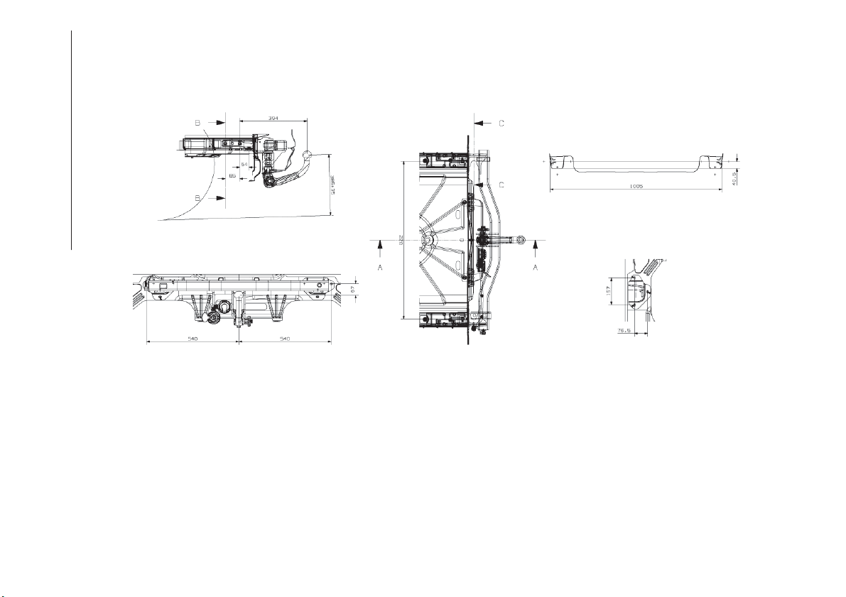
Assembly diagram
The tow hook structure must be secured to the body in the points shown in the figure fig. 112.
IMPORTANT To install a tow hook contact a Fiat Dealership.
112
F1B0168C
142
STARTING AND DRIVING
WARNING
134) The ABS with which the car is
equipped will not control the braking
system of the trailer. Particular caution is
required on slippery roads.
135) Never modify the braking system of
the vehicle to control the trailer brake. The
trailer braking system must be fully
independent of the car’s hydraulic system.
143
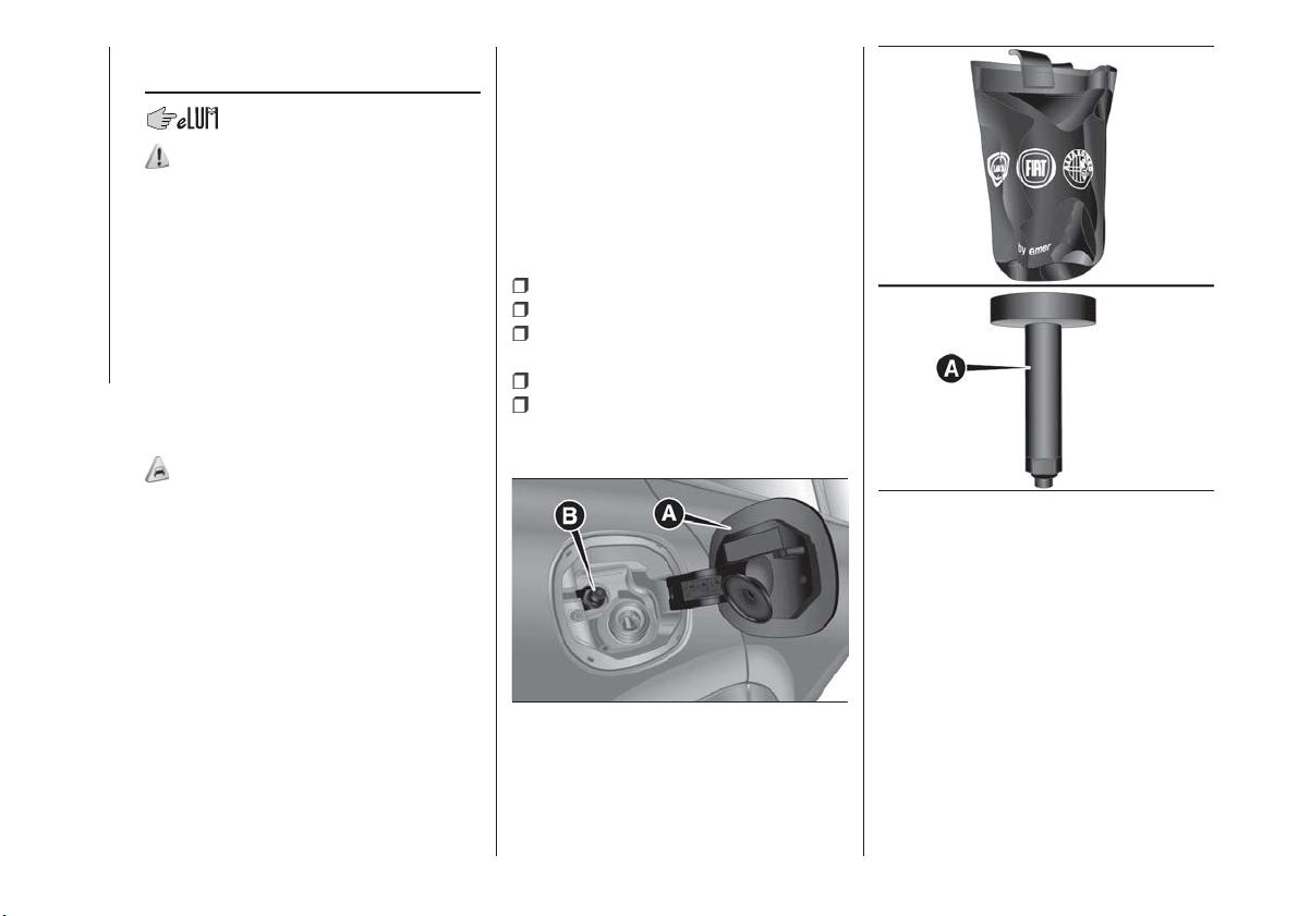
REFUELLING THE
VEHICLE
136) 137) 138)
PETROL ENGINES
Only use unleaded petrol with a number
of octanes (R.O.N.) not lower than 95
(EN228 specification).
IMPORTANT Never introduce leaded
petrol to the tank, even in small
amounts in an emergency, as this
would damage the catalytic converter
beyond repair.
DIESEL ENGINES
76)
Only use Diesel for motor vehicles (EN
590 specification).
When using or parking the vehicle for a
long time in the mountains or cold
areas, it is advisable to refuel using
locally available diesel. In this case, it is
also advisable to keep the tank over
50% full.
LPG ENGINES
The gas filler is located next to the
petrol filler cap. It has a check valve,
located in the filler body itself.
To access the LPG filler, open the
access flap A fig. 113and undo the cap
B.
Observe the following precautions
during the refuelling operation:
switch off the engine;
engage the electric parking brake;
put the ignition device in the STOP
position;
do not smoke;
hand the special adapter A
fig. 114over to the qualified LPG
refuelling personnel.
IMPORTANT Depending on the country,
there are various types of adapters for
LPG refuelling pumps. The filler adapter
A fig. 114, supplied with the vehicle and
located in a special case, is specifically
designed for the country in which the
vehicle is sold. If you are in a different
country, find out what type of adaptor is
used there.
113
F1B0614C
114
F1B0615C
144
STARTING AND DRIVING
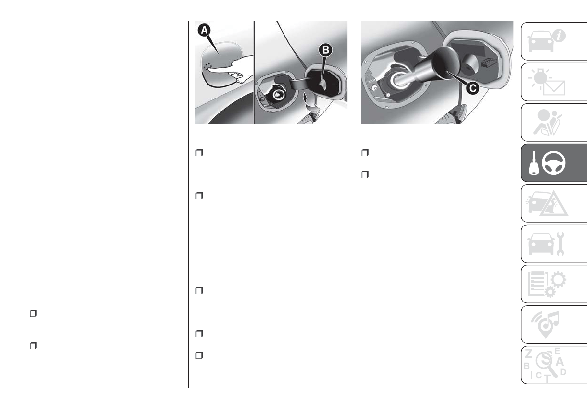
IMPORTANT Before refuelling with LPG,
the qualified personnel must make sure
that the adapter is correctly screwed
onto the filler.
IMPORTANT Look after the LPG
adapter carefully so that it does not get
damaged.
IMPORTANT Only use LPG for motor
vehicles.
IMPORTANT Only use the adapter
supplied with the vehicle as it is
equipped with a dedicated fuel
pre-filter.
REFUELLING
PROCEDURE
"Capless Fuel" is a device at the
opening for the fuel tank which opens
and re-closes automatically when the
fuel supply gun is introduced/removed.
The "Capless Fuel" device is provided
with an inhibitor which prevents
refuelling with incorrect fuel.
Opening the flap
To refuel proceed as follows:
open the flap A fig. 115 after
releasing it by pressing in the point
shown;
introduce the dispenser in the filler
and refuel;
after refuelling, before removing the
dispenser, wait for at least 10 seconds
in order for the fuel to flow inside the
tank;
then remove the dispenser from the
filler and close flap A.
The flap is provided with a dust cover
gaiter B which prevents deposits of
impurities and dust at the end of the
filler when the flap is closed.
Emergency refuelling
Proceed as follows:
open the boot and take adaptor C
fig. 116, located in the tool box or in the
Fix&Go kit container (according to the
versions);
open flap A fig. 115, as described
previously;
introduce the adaptor in the filler as
shown and refuel;
after refuelling, remove the adapter
and close the flap;
finally refit the adaptor in the boot.
Fuel - Vehicle
compatibility
identification Graphic
symbol for informing
consumers in
accordance with
EN16942
The symbols shown below facilitated
recognising the correct fuel type to be
used on your car.
Before proceeding with refuelling, check
the symbols inside the fuel filler flap
(where provided) and compare them
with the symbols shown on the fuel
pump (where provided).
115
F1B0164C
116
F1B0165C
145
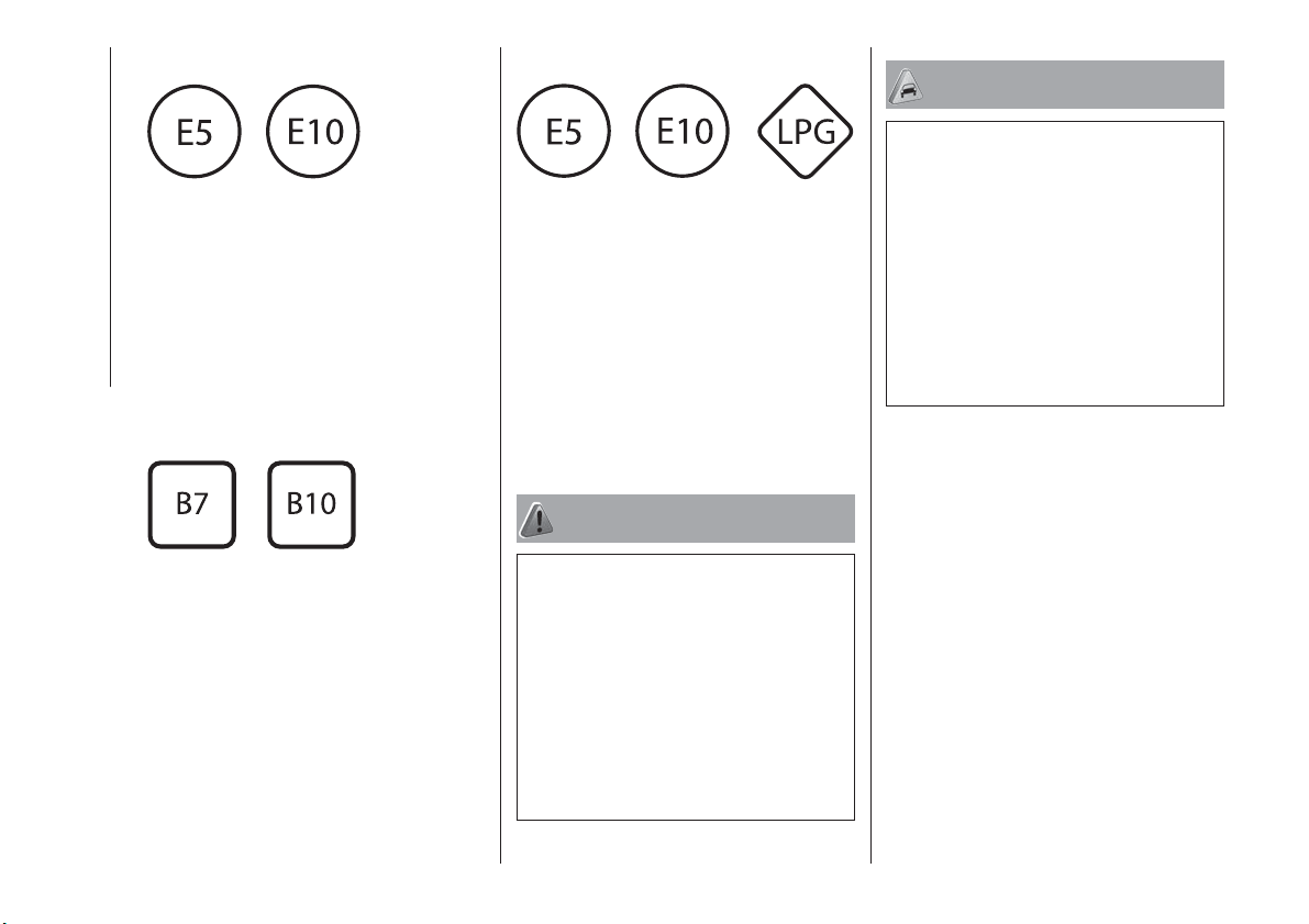
Symbols for petrol powered cars
E5: Unleaded petrol containing up to
2.7% (m/m) oxygen and with maximum
5.0% (V/V) ethanol compliant with
EN228
E10: Unleaded petrol containing up to
3.7% (m/m) oxygen and with maximum
10.0% (V/V) ethanol compliant with
EN228
Symbols for diesel powered cars
B7: Diesel containing up to 7% (V/V) of
FAME (Fatty Acid Methyl Esters)
compliant with the EN590 specification
B10: Diesel containing up to 10% (V/V)
of FAME (Fatty Acid Methyl Esters)
compliant with the EN16734
specification
Symbols for petrol/LPG bi-fuel cars
E5: Unleaded petrol containing up to
2.7% (m/m) oxygen and with maximum
5.0% (V/V) ethanol compliant with
EN228
E10: Unleaded petrol containing up to
3.7% (m/m) oxygen and with maximum
10.0% (V/V) ethanol compliant with
EN228
LPG: Automotive LPG compliant with
EN589
WARNING
136) Do not apply any object/plug to the
end of the filler which is not provided for
the car. The use of non-compliant
objects/plugs could cause a pressure
increase inside the tank, resulting in
dangerous situations.
137) Do not bring naked flames or lit
cigarettes near to the fuel filler: fire risk.
Keep your face away from the fuel filler to
prevent breathing in harmful vapours.
138) Do not use a mobile phone near the
refuelling pump: risk of fire.
IMPORTANT
76) Vehicles with a diesel engine must only
be filled with diesel fuel for motor vehicles,
in compliance with European Standard EN
590. The use of other products or mixtures
may damage the engine beyond repair and
consequently invalidate the warranty, due
to the damage caused. If you accidentally
introduce other types of fuel into the tank,
do not start the engine. Empty the tank. If
the engine has been run for even an
extremely limited amount of time, you must
not only drain the fuel tank, but the rest of
the supply circuit as well.
146
STARTING AND DRIVING
IN AN EMERGENCY
A punctured tyre or a burnt-out bulb?
At times, a problem may interfere with
our journey.
The pages on emergencies can help
you to deal with critical situations
independently and with calm.
In an emergency we recommend that
you call the freephone number found in
the Warranty Booklet.
It is also possible to call the national or
international universal freephone
number to search for the nearest Fiat
Dealership.
HAZARD WARNING LIGHTS .....148
BULB REPLACEMENT.........148
REPLACING FUSES ..........154
CHANGING A WHEEL .........159
FIX&GO AUTOMATIC KIT .......163
EMERGENCY STARTING .......166
FUEL CUT-OFF SYSTEM .......168
AUTOMATIC TRANSMISSION -
LEVER UNLOCK ............168
AUTOMATIC TRANSMISSION -
KEY REMOVAL .............169
DUAL CLUTCH AUTOMATIC
TRANSMISSION - LEVER
UNLOCK .................170
DUAL CLUTCH AUTOMATIC
TRANSMISSION - REMOVING
THEKEY .................171
TOWING THE VEHICLE ........172
147
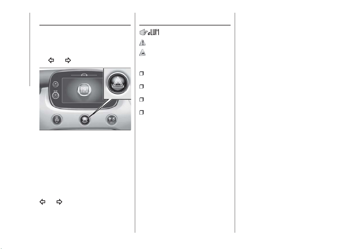
HAZARD WARNING
LIGHTS
CONTROL
Press the button fig. 117 to switch the
lights on/off.
When the hazard warning lights are on,
the
and warning lights flash.
IMPORTANT The use of hazard warning
lights is governed by the highway code
of the country you are driving in:
comply with legal requirements.
Emergency braking
In the event of emergency braking the
hazard warning lights switch on
automatically as well as warning lights
and in the instrument panel.
The lights switch off automatically when
emergency braking ceases.
BULB
REPLACEMENT
139) 140) 141) 142)
77)
GENERAL
INSTRUCTIONS
Before replacing a bulb check the
contacts for oxidation;
replace blown bulbs with others of
the same type and power;
after replacing a headlight bulb,
always check its alignment;
when a light is not working, check
that the corresponding fuse is intact
before replacing the bulb. For the
location of fuses, refer to the paragraph
“Replacing fuses” in this chapter.
IMPORTANT When the weather is cold
or damp or after heavy rain or washing,
the surface of headlights or rear lights
may steam up and/or form drops of
condensation on the inside. This is a
natural phenomenon due to the
difference in temperature and humidity
between the inside and the outside of
the glass which does not indicate a
fault and does not compromise the
normal operation of lighting devices.
The mist disappears quickly when the
lights are turned on, starting from the
centre of the diffuser, extending
progressively towards the edges.
117
F1B0632C
148
IN AN EMERGENCY
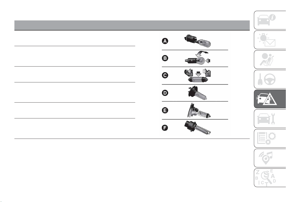
TYPES OF BULBS
The vehicle is equipped with the following bulbs:
Glass bulbs (type A):
they are press-fitted. Pull to extract.
Bayonet-type bulbs (type B): to remove them from their holder,
press the bulb and turn it anticlockwise, then extract it.
Tubular bulbs (type C): release them from their contacts to remove.
Halogen bulbs (type D): to remove the bulb, turn the connector to
the side and pull it out.
Halogen bulbs (type E): to remove the bulb, turn it anticlockwise.
Xenon gas discharge bulb (type F): to remove the bulb, contact a
Fiat Dealership.
149
Light bulbs Type Power Figure reference
Front side lights/Daytime running lights (DRL) W21W 21W B
Rear
side/brake light P21W 21W B
Main beam/dipped beam headlights (halogen) H4 60/55W D
Main beam/dipped beam headlights (Xenon gas discharge) D5S 25W F
Front direction indicators PY21W 21W B
Rear direction indicators P21W 21W B
Side direction indicators (on door mirror) WY5W 5W A
Third brake light LED – –
Number plate W5W 5W A
Fog lights H8 35W E
Rear fog light P21W 21W B
Reversing light P21W 21W B
Front ceiling light C5W 5W A
Front roof lights (sun visors) C5W 5W A
Rear ceiling light (versions without sunroof) XENON 6W A
Rear ceiling lights (versions with sunroof) C5W 5W C
Boot ceiling lights W5W 5W A
150
IN AN EMERGENCY
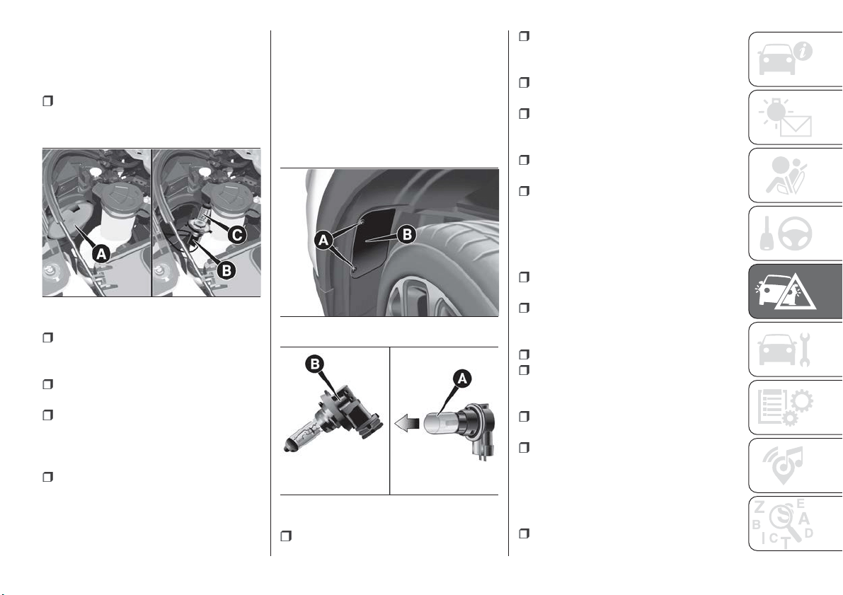
REPLACING AN
EXTERNAL BULB
Dipped/main beam headlights
To replace the bulb, proceed as follows:
working from inside the engine
compartment, remove the rubber cap A
fig. 118, using the dedicated tab;
turn the bulb and bulb holder
assembly anticlockwise and then
remove it sliding it outwards;
disconnect the electrical connector B
and replace the bulb C.
then insert the bulb and bulb holder
assembly in its housing and turn it
clockwise, making sure that it is locked
correctly;
refit the rubber cap A.
IMPORTANT Only replace the bulb
when the engine is off. Also ensure that
the engine is cold, to prevent the risk of
burns.
Xenon gas discharge main
beam/dipped beam headlights
For replacing these bulbs, contact a
Fiat Dealership.
Side lights/daytime running lights
(DRL)
To replace the bulbs, proceed as
follows:
steer the car wheels completely
inwards;
undo screws A fig. 119 using the
screwdriver provided and remove
inspection flap B;
identify the side light/daytime running
light bulb;
turn the bulb and bulb holder
assembly anticlockwise and then
remove it sliding it outwards;
replace the bayonet-fitted bulb A
fig. 120;
finally, refit the inspection flap B
fig. 119, fully tightening fixing screws A.
Front direction indicators
To replace the bulbs, proceed as
follows:
steer the car wheels completely
inwards;
undo screws A fig. 119 using the
screwdriver provided and remove
inspection flap B;
identify the direction indicator bulb;
turn the bulb and bulb holder
assembly anticlockwise and then
remove it sliding it outwards;
replace the bayonet-fitted bulb A
fig. 120;
finally, refit the inspection flap B
fig. 119, fully tightening fixing screws A.
Fog lights
To replace the bulbs, proceed as
follows:
steer the car wheels completely
inwards;
118
F1B0146C
119
F1B0147
120
F1B0253C
151
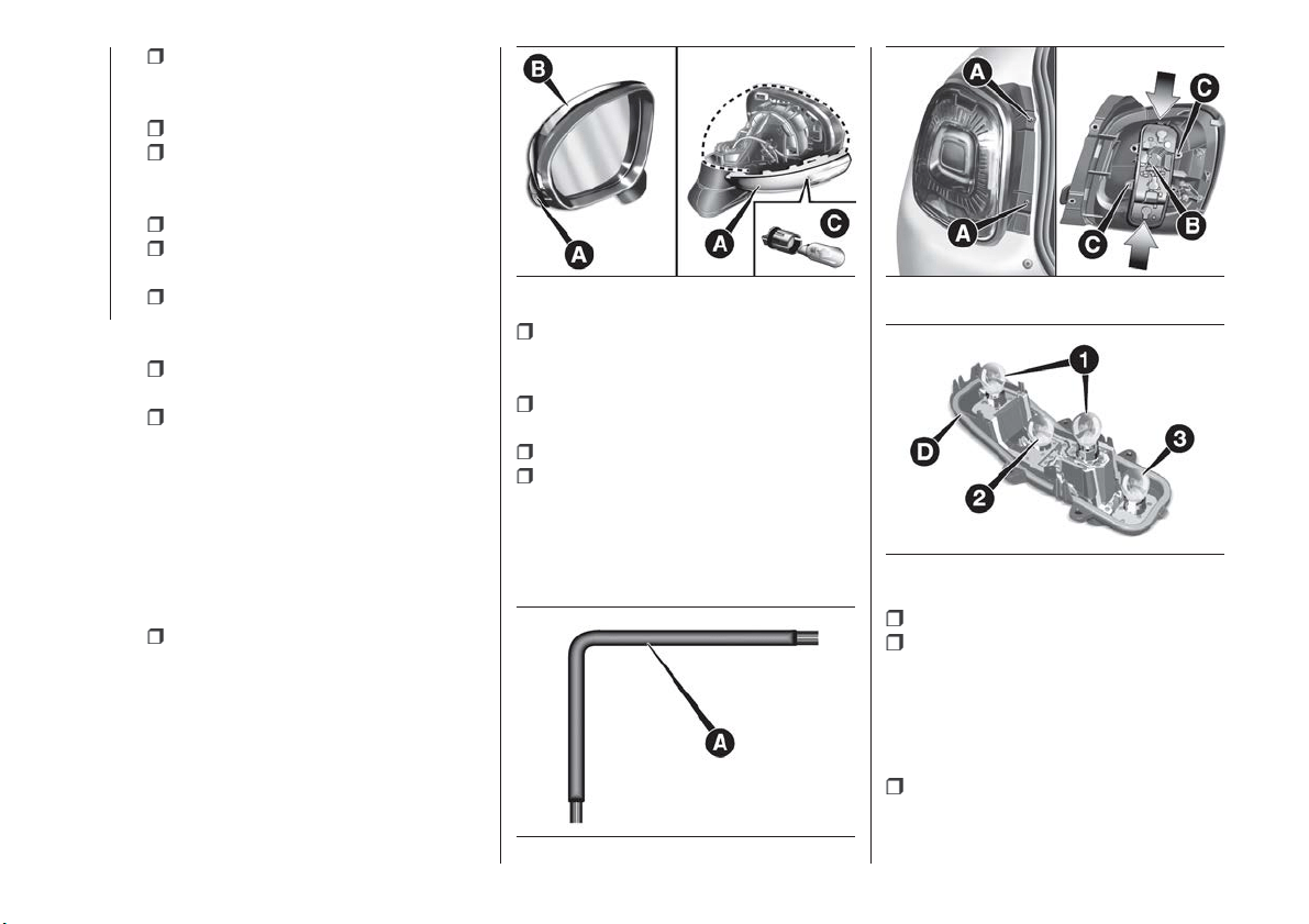
undo screws A fig. 119 using the
screwdriver provided and remove
inspection flap B;
identify the fog light;
turn the bulb and bulb holder
assembly anticlockwise and then
remove it sliding it outwards;
disconnect the electrical connector;
replace the bulb-bulb holder
assembly B fig. 120;
reconnect the electrical connector to
the new bulb-bulb holder; then insert it
making sure it is locked correctly;
insert the assembly by turning it
clockwise and locking it correctly;
finally, refit the inspection flap B
fig. 119, fully tightening fixing screws A.
Side turn light
IMPORTANT The procedure is
described by way of example only. It is
advisable to contact a Fiat Dealership
for bulb replacement.
To replace the bulb, proceed as follows:
remove the cap B fig. 121 from the
door mirror very carefully (use a suitable
tool to prevent damaging the painted
parts) around the mirror frame (as
shown in the figure);
remove the lens A and then remove
the bulb C pulling it from the respective
bulb holder.
fit the new bulb, making sure it is
correctly locked;
refit the bulb holder on lens A;
refit cap B on the door mirror
correctly, ensuring that it locks correctly.
Rear light cluster
To replace the bulbs, proceed as
follows:
open the tailgate;
using the tool A fig. 122 provided
(located in the on-board document
pouch), undo the two screws A
fig. 123, then release the light cluster
from the respective pin fasteners pulling
it carefully;
disconnect the central connector B,
then undo the two screws C;
121
F1B0149C
122
F1B0022C
123
F1B0151C
124
F1B0152C
152
IN AN EMERGENCY
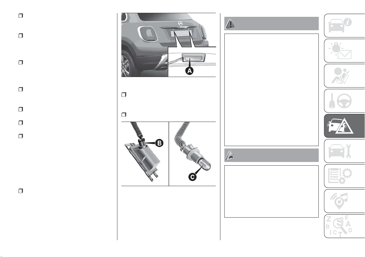
release the tabs shown by the arrows
and extract the bulb holder assembly D
fig. 124;
identify the bulb to be replaced
(1 Positions/Stop - 2 Direction indicator
- 3 Rear fog light (where provided) or
Reverse);
all bulbs are "bayonet-fitted"; to
replace them, press slightly and turn at
the same time: anticlockwise to extract;
clockwise to insert;
reposition the bulb holder assembly
D correctly in the headlight body;
proceed until you hear the tabs click;
fasten the two screws C fig. 123 and
reconnect the central connector B;
refit the lens by screwing the two
screws A completely;
close the tailgate.
3
rd
brake lights
The 3
rd
brake lights are LED-based. To
replace them, contact a Fiat Dealership.
Number plate lights
To replace the bulbs, proceed as
follows:
using the screwdriver provided,
remove the lenses A fig. 125 working in
the point shown;
turn the bulb holder B
fig. 126 anticlockwise, extract the bulb
C and replace it.
finally, refit the lenses.
NOTE Before removing the lens unit,
put a protection (e.g. cloth) on the tip of
the screwdriver, in order not to damage
the lens itself.
WARNING
139) Before replacing the bulb, wait for the
exhaust ducts to cool down: DANGER OF
SCALDING!
140) Modifications or repairs to the electric
system that are not carried out properly or
do not take the system technical
specifications into account can cause
malfunctions leading to the risk of fire.
141) Halogen bulbs contain pressurised
gas, in the case of breakage they may
burst causing glass fragments to be
projected outwards.
142) Only replace the light bulbs when the
engine is off and in a position that does not
interfere with traffic and lets you safely
replace them (see the description in the
“Replacement” paragraph). Also ensure
that the engine is cold, to prevent the risk
of burns.
IMPORTANT
77) Halogen bulbs must be handled
holding the metallic part only. Touching the
transparent part of the bulb with your
fingers may reduce the intensity of the
emitted light and even reduce the lifespan
of the bulb. In the event of accidental
contact, wipe the bulb with a cloth
moistened with alcohol and let the bulb dry.
125
F1B0153C
126
F1B0154C
153
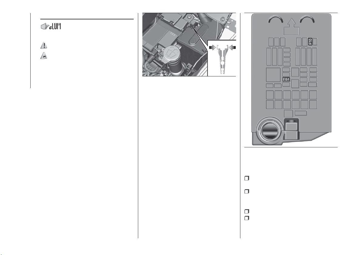
REPLACING FUSES
INTRODUCTION
143) 144) 145) 146)
78) 79)
Fuses protect the electrical system:
they intervene (blow) in the event of a
failure or improper action on the
system.
Fuse extracting pliers
To replace a fuse, use the pliers hooked
to the side of the engine compartment
fuse box cover (see fig. 127 ).
The pliers have two different ends,
specifically designed to remove the
different types of fuses present in the
vehicle.
To take out the pliers, grab them from
the upper tabs, press and pull upwards.
After being used, the pliers should be
positioned properly in their housing,
grabbing them from the upper tabs,
pressing and pushing them until a click
is heard.
FUSE LOCATION
Fuses are grouped together in the fuse
boxes located in the engine
compartment, under the dashboard
and inside the boot.
ENGINE COMPARTMENT
FUSE BOX
The fuse box is located by the side of
the battery fig. 128.
To access the fuses, proceed as
follows:
fully tighten screw A fig. 129, using
the screwdriver provided;
at the same time slowly rotate the
screw anticlockwise, until resistance is
encountered (do not overtighten);
slowly release the screw;
opening is indicated by the entire
screw head coming out of its housing;
127
F1B0187C
128
F1B0191C
154
IN AN EMERGENCY
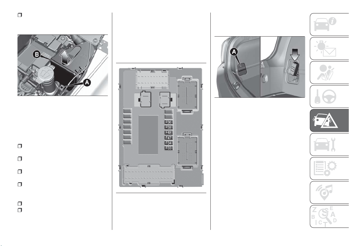
remove cover B, sliding it upwards
on the side guides, as indicated in the
figure.
The number identifying the electrical
component corresponding to each fuse
is shown on the cover.
Once the fuse has been replaced,
proceed as follows:
correctly refit the cover B in the side
guides of the casing;
slide it down completely from the
top;
fully tighten screw A, using the
screwdriver provided;
at the same time slowly rotate the
screw clockwise, until resistance is
encountered (do not overtighten);
slowly release the screw;
closure is indicated by the securing
of the entire screw head in its housing.
DASHBOARD FUSE BOX
The fuse box fig. 130 is located near
the left side of the steering column and
the fuses can be accessed easily from
the lower part of the dashboard.
For fuse replacement, contact a Fiat
Dealership.
BOOT FUSE BOX
Open inspection cover A fig. 131 and
access the fuses in fuse box B fig. 132.
129
F1B0190C
130
F1B0193C
131
F1B0194C
155
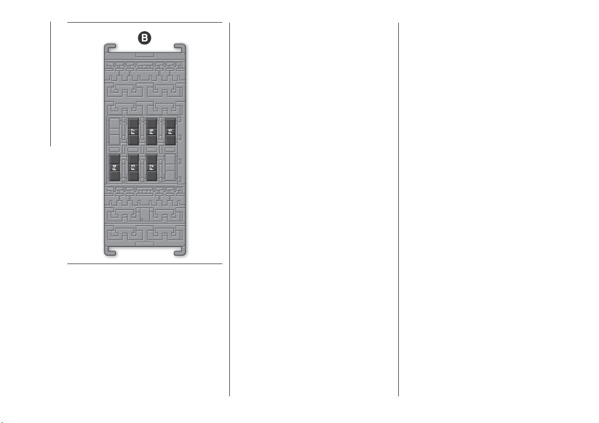
156
IN AN EMERGENCY
132
F1B0195C
ENGINE COMPARTMENT FUSE BOX
USERS FUSE AMPERE
Horn F10
10
Power supply for cigar lighter/power socket F84 20
DASHBOARD FUSE BOX
USERS FUSE AMPERE
Front electric window (passenger side) F33 20
Fr
ont electric window (driver side) F34 20
Power supply to Uconnect
™ system, Climate Control System,
Rear-view mirror folding system, EOBD system, USB / AUX port,
Rear side roof light (convertible version)
F36 15
Dead Lock device (Driver side door unlocking for
versions/markets, where provided)/Door unlocking/Central
locking/Electric tailgate unlocking
F38 20
Rear left electric window F47 20
Rear right electric window F48 20
157
BOOT FUSE BOX
NOTE The configuration of the boot may vary in accordance with the equipment on the vehicle.
Fuse box B
USERS FUSE AMPERE
HI-FI system F2 20
Electric
sun roof F3 20
Front seat electric lumbar adjustment (driver guide) F4 7.5
Electric front seat adjustment (driver side) F5 30
Electric front seat adjustment (driver side and passenger side) F6 7.5
Electric front seat lumbar adjustment (driver side and passenger
side)
F7 30
158
IN AN EMERGENCY

WARNING
143) If the replaced fuse blows again,
contact a Fiat Dealership.
144) Never replace a fuse with another
with a higher amp rating; DANGER OF
FIRE
145) If a fuse NOT indicated in this or the
previous page is used, contact a Fiat
Dealership.
146) Before replacing a fuse, make sure
that the ignition device is at STOP, that the
key, if mechanical, has been removed and
that all devices are switched off and/or
disconnected.
IMPORTANT
78) Never replace a fuse with metal wires
or anything else.
79) If it is necessary to wash the engine
compartment, take care not to directly hit
the fuse box and the window wiper motor
with the water jet.
CHANGING A WHEEL
JACK
154) 155)
Please note that:
the jack weight is 2.8 kg;
the jack requires no adjustment;
the jack cannot be repaired and in
the event of a fault it must be replaced
by another genuine one;
no tool other than its cranking device
may be fitted on the jack.
Maintenance
prevent any dirt from depositing on
the "worm screw";
keep the "worm screw" lubricated;
never modify the jack.
Conditions for non-use
temperatures below −40°C;
on sandy or muddy ground;
on uneven ground;
on steep roads;
in extreme weather conditions:
thunderstorms, typhoons, hurricanes,
blizzards, storms, etc...
in direct contact with the engine or
for repairs under the car;
on boats.
CHANGING PROCEDURE
147) 148) 149) 150) 151) 152) 153)
Proceed as follows:
stop the car in a position that is not
dangerous for oncoming traffic where
you can change the wheel safely. The
ground must be flat and sufficiently
compact;
stop the engine, engage the hazard
warning lights and the electric parking
brake;
engage first gear or reverse or, for
versions with automatic transmission,
move the lever to position P (Park);
wear the reflective safety jacket
(compulsory by law) before getting out
of the car;
open the luggage compartment and
set the adjustable load platform in the
diagonal position (see "Luggage
Compartment" section of the "Getting
to know your car" chapter);
take out the tool bag supplied,
anchored to the boot mat by special
fasteners. The bag contains fig. 133:
jack A; screwdriver B; adaptor C for
refuelling in the event of an emergency;
pin D for centring the wheel (where
provided, to be used in the spare wheel
fitting procedure); special anti-theft nut
E (where provided, to be used in the
wheel stud bolt fitting/removal
procedure); chock F for blocking the
159
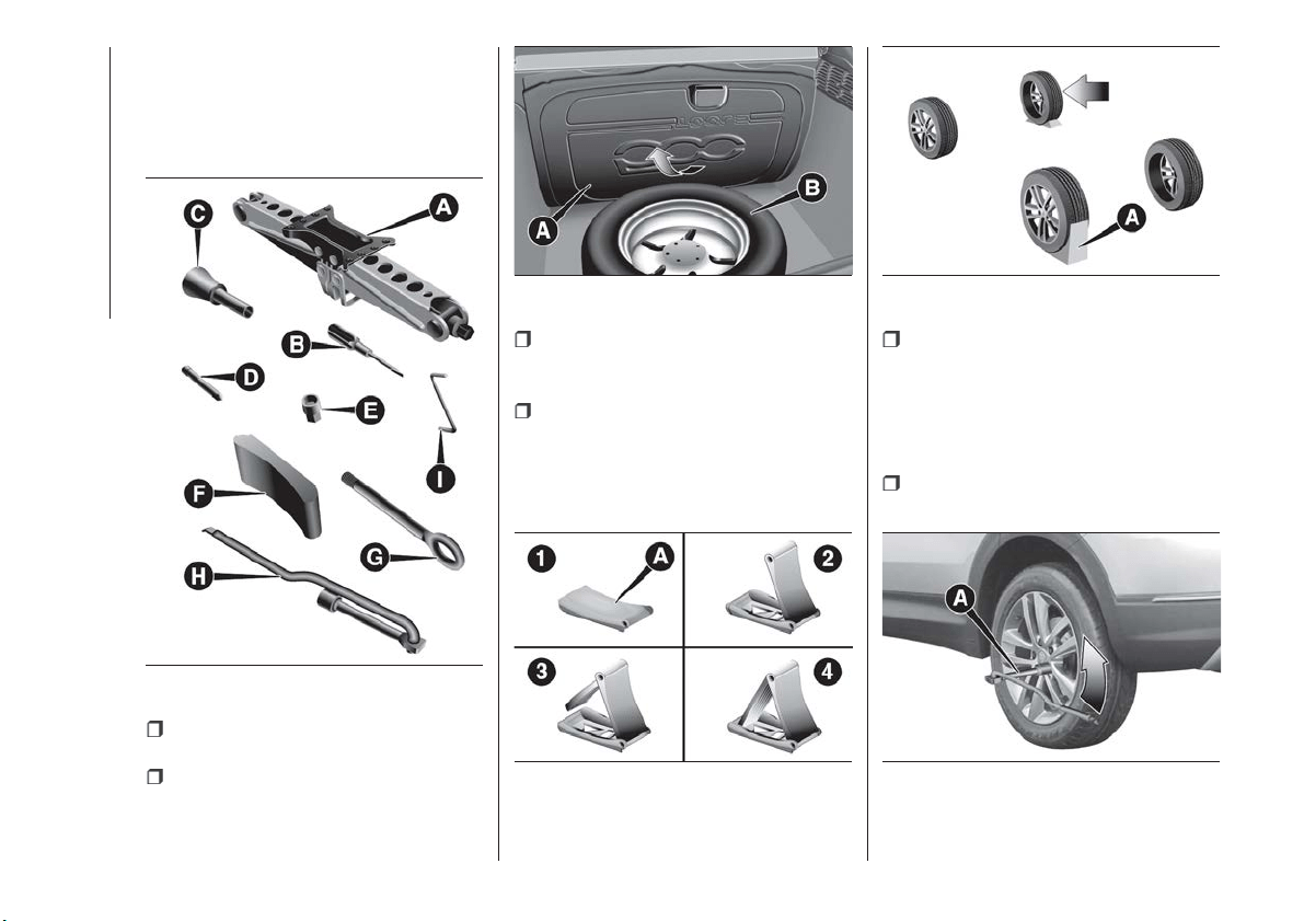
wheels and the vehicle; tow hook G;
key H for the wheel stud bolts and the
jack; Allen key I for emergency
operation of the sun roof (where
provided);
lift up the mat A fig. 134 and take out
the space-saver spare wheel B;
position the spare wheel and tool
bag next to the wheel for changing;
take the chock A (where provided)
fig. 135 and fold it out as shown in the
diagram;
place the chock A on the wheel
diagonally opposite the one to be
replaced (see fig. 136 ) to prevent the
car from moving irregularly when it is
lifted from the ground;
using the spanner A fig. 137, loosen
the fixing stud bolts by about one turn.
For versions with alloy rims it is a good
idea to "shake" the car to facilitate
detachment of the rim from the wheel
hub.
position the jack under the car, near
the wheel to be changed;
133
F1B0218C
134
F1B0219C
135
F1B0220C
136
F1B0221C
137
F1B0223C
160
IN AN EMERGENCY
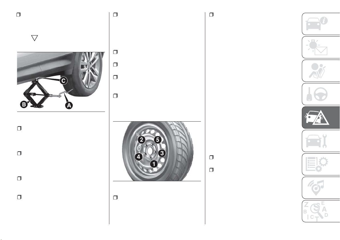
until the top splined area fits correctly
into the side member C of the car, next
to the
symbol on the side member
itself;
alert any bystander that the car is
about to be raised; all persons should
be kept away from the car and nobody
must touch it until it has been lowered;
use the wrench A to turn the jack
(clockwise) and raise the car until the
wheel is a few centimetres off the
ground;
with the wrench A, completely
unscrew the stud bolts and remove the
wheel with the puncture;
make sure the contact surfaces
between space-saver wheel and hub
are clean so that the mounting stud
bolts will not come loose;
to simplify fitting of the space-saver
spare wheel, screw the centring pin into
the highest hole in the wheel hub then
fit the wheel, screwing on the first stud
bolt by hand for at least two turns of
the thread;
remove the centring pin and screw
on the other stud bolts by hand;
using the wrench A, screw down all
the stud bolts.
turn the wrench A (anticlockwise) on
the hexagonal part of the jack to lower
the car, then extract the jack;
use the wrench A to fully tighten all
the stud bolts, working in a criss-cross
fashion as per the numerical sequence
illustrated in fig. 139;
place the wheel with the puncture in
the luggage compartment upside down
(with the finished side facing upwards),
then put the jack and the tools used
away in the correct positions;
replace the mat in the luggage
compartment, then return the
adjustable load platform to the level
position (see "Luggage Compartment"
section of the "Getting to know your
car" chapter);
Restore the standard wheel as soon as
possible, also because, since it is larger
than the space-saver spare wheel,
when it is placed in the relative
compartment the floor of the luggage
compartment becomes slightly uneven.
CHANGING A WHEEL
(versions with
subwoofer)
Versions with space-saver wheel
On these versions, the tools for
replacing the wheel are located in a
dedicated bag in the luggage
compartment.
In the case of a puncture, proceed as
follows:
open the luggage compartment and
then lift up the mat;
unscrew the locking device A
fig. 140, remove the space-saver spare
wheel B and fit it in place of the
punctured tyre, carrying out the
procedures described previously.
138
F1B0224C
139
F1B0225C
161
insert the wrench A fig. 138 on the
hexagonal part of the jack B to extend it
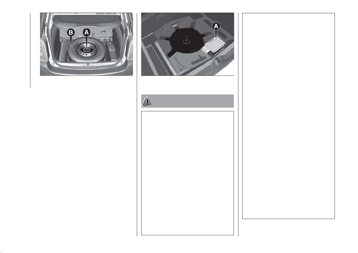
When the operation is completed, lower
the luggage compartment mat and
position the punctured tyre on top of it,
ensuring that it is locked correctly so
that it doesn’t move during driving.
Versions with “Fix&Go Automatic”
kit
To find the “Fix&Go Automatic” kit,
open the luggage compartment then lift
up the mat: the kit A fig. 141 is located
on the right-hand side.
WARNING
147) If left in the passenger compartment,
the punctured wheel and jack constitute a
serious risk to the safety of occupants in
the event of accidents or sharp braking.
Therefore, always place both the jack and
punctured wheel in the dedicated housing
in the boot.
148) It is extremely dangerous to attempt
to change a wheel on the side of the
vehicle next to the driving lane: make sure
that the vehicle is at a sufficient distance
from the road, to avoid being run over.
149) Alert other drivers that the car is
stationary in compliance with local
regulations: hazard warning lights, warning
triangle, etc. Any passengers on board
should leave the car, especially if it is
heavily laden. Passengers should stay
away from on-coming traffic while the
wheel is being changed. For safety
reasons, always block the wheels with the
chocks provided.
150) The vehicle's driving characteristics
will be modified with the space-saver wheel
fitted. Avoid violent acceleration and
braking, abrupt steering and fast cornering.
The overall duration of the space-saver
wheel is about 3000 km, after which the
relevant tyre must be replaced with another
one of the same type. Never install a
standard tyre on a rim that is designed for
use with a space-saver wheel. Have the
wheel repaired and refitted as soon as
possible. Using two or more space-saver
wheels at the same time is forbidden. Do
not grease the threads of the stud bolts
before fitting them: they might slip out
when driving!
151) The space-saver wheel is specific to
your vehicle: do not use it on other models,
or use the space-saver wheel of other
models on your vehicle. The space-saver
wheel must only be used in the event of an
emergency. Never use it for more than
strictly necessary and never exceed
80 km/h. On the space-saver wheel there
is an orange label, summarising the main
warnings regarding space-saver wheel
usage restrictions. Never remove or cover
the sticker.
152) The space-saver wheel cannot be
fitted with snow chains. If a front (drive) tyre
is punctured and chains are needed, use a
standard wheel from the rear axle and
install the space-saver wheel on the rear
axle. In this way, with two normal drive
wheels at the front axle, it is possible to
use snow chains (this instruction is also
valid for 4x4 versions).
140
F1B0453C
141
F1B0452C
162
IN AN EMERGENCY
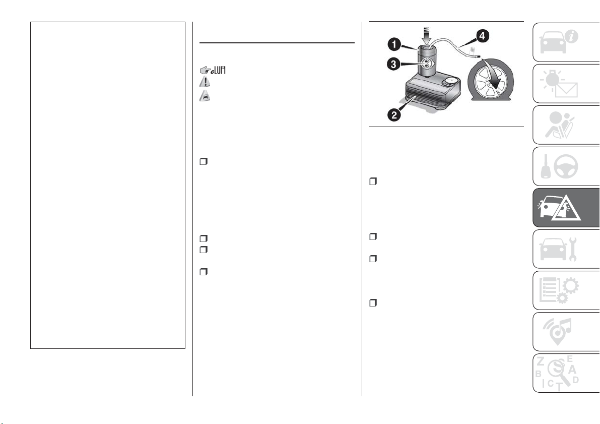
153) Never tamper with the inflation valve.
Never introduce tools of any kind between
the rim and the tyre. Check tyre and
space-saver wheel pressures regularly,
complying with the values given in the
"Technical specifications" chapter.
154) The jack is a tool developed and
designed only for changing a wheel, if a
tyre gets punctured or damaged, on the
vehicle with which it is supplied or on other
vehicles of the same model. Any other use,
e.g. to jack up other vehicle models or
different things, is strictly prohibited. Never
use it to carry out maintenance or repairs
under the vehicle or to change
summer/winter wheels and vice versa: we
advise you to contact a Fiat Dealership.
Never go under the raised vehicle: use it
only in the positions indicated. Do not use
the jack for loads higher than the one
shown on its label. Never start the engine
with car raised. If the car is raised more
than necessary, everything can become
more unstable, with the risk of the car
dropping violently. Thus, lift the car only as
needed in order to access the space-saver
spare wheel.
155) When turning the jack handle make
sure that it can turn freely without scraping
your hand against the ground. The moving
components of the jack ("worm screw" and
joints) can also cause injuries: do not touch
them. If you come into contact with
lubricating grease, clean yourself
thoroughly.
FIX&GO AUTOMATIC
KIT
(where provided)
156) 157)
80)
DESCRIPTION
The Fix&Go quick tyre repair kit
fig. 142 is located in the boot, inside a
dedicated container and consists of:
one cartridge 1 containing sealant
and fitted with: transparent tube for
injecting the sealant 4 and sticker 3 with
the wording “Max. 80 km/h” to be
placed in a clearly visible position (e.g.
on the dashboard) after repairing the
tyre;
one compressor 2;
one leaflet containing instructions for
using the kit;
a pair of gloves located in the hose
compartment of the cartridge 4.
REPAIR PROCEDURE
Proceed as follows:
stop the car in a position that is not
dangerous for oncoming traffic where
you can carry out the procedure safely.
The ground must be flat and sufficiently
compact;
stop the engine, engage the hazard
warning lights and the parking brake;
wear the reflective safety jacket
before getting out of the car (anyway
comply with the laws in force in the
country you are driving in);
Insert the cartridge 1 containing the
sealant in the proper compartment of
the compressor 2, pressing it down
hard fig. 142. Remove the speed limit
sticker 3 and apply it in a clearly visible
position fig. 143;
142
P2000158
163
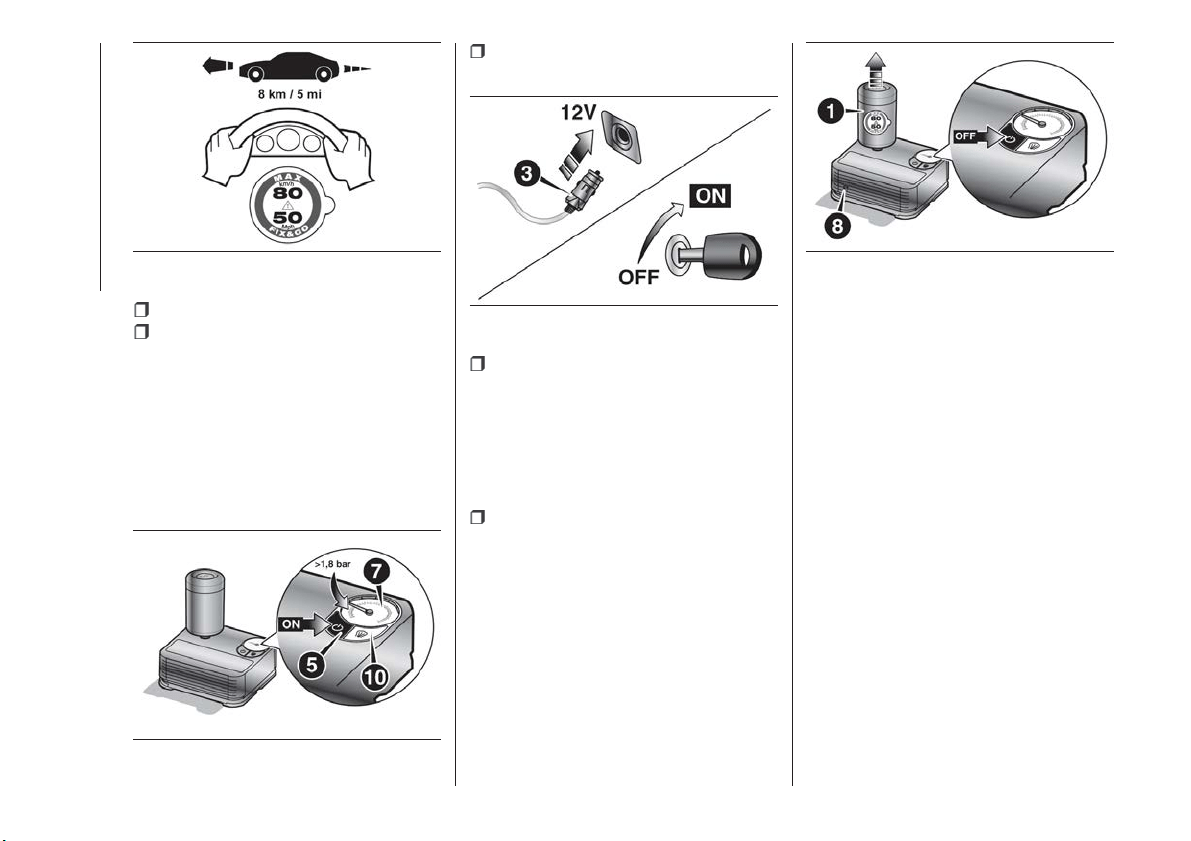
wear the gloves;
remove the cap from the tyre valve
and connect and firmly tighten the
transparent tube of the sealing fluid 4
fig. 142. If a 250 ml cartridge is present
the housing of the transparent tube is
provided with removable ring to
facilitate extraction. Make sure that the
ON-OFF button 5 fig. 144 is in the off
position (button not pressed);
insert the electrical connector 6
fig. 145 into the 12V socket on the car;
operate the compressor by pressing
the ON-OFF button 5 fig. 144. When
the pressure shown in the Owner
Handbook or on the specific label
appears on the pressure gauge 7, stop
the compressor by pressing the
ON-OFF button 5 again;
disconnect the cartridge 1 from the
compressor, by pressing the release
button 8 and lifting the cartridge
1 upwards fig. 146.
If the pressure gauge 7
fig. 144 indicates a pressure lower than
1.8 bar / 26 psi 15 minutes after
starting the compressor, switch off the
compressor, disconnect the sealing
fluid tube 4 from the tyre valve and
remove the cartridge 1 from the
compressor fig. 146.
Move the car by approximately 10 m to
distribute the sealant; stop the car
safely, engage the handbrake and use
the black inflation pipe 9 fig. 147 to
reach the required pressure. If also in
this case, the pressure is lower than
1.8 bar / 26 psi after 15 minutes, do not
resume driving but contact a Fiat
Dealership.
143
P2000162
144
P2000160
145
P2000159
146
P2000161
164
IN AN EMERGENCY
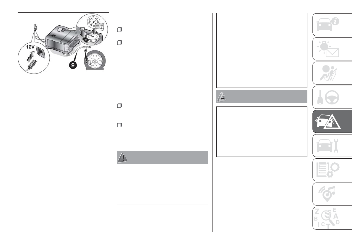
After driving for about 8 km / 5 miles,
position the car in a safe and suitable
area and engage the handbrake. Take
the compressor and restore pressure
using the black inflation tube 9 fig. 147.
If the pressure shown is higher than
1.8 bar / 26 psi, restore the pressure
and drive safely to a Fiat Dealership as
soon as possible. If, however, the
pressure is lower than 1.8 bar / 26 psi,
do not resume driving but contact a Fiat
Dealership.
INFLATION PROCEDURE
Proceed as follows:
stop the car safely, as described
above, and operate the handbrake;
extract the black inflation tube 9
fig. 147 and screw it firmly onto the tyre
valve. Follow the instructions shown in
fig. 145 and fig. 147.
Press the air release button 10
fig. 144 to adjust any tyre overpressure.
CARTRIDGE
REPLACEMENT
Proceed as follows:
only use original Fix&Go cartridges,
which can be purchased from the Fiat
Dealership.
to remove the cartridge 1 fig. 142,
press the release button 8 fig. 146 and
lift it.
WARNING
156) The information required by the
applicable regulation is indicated on the
Fix&Go kit package label. Carefully read the
label on the cartridge before use, avoid
improper use. The kit should be used by
adults and cannot be used by children.
157) IMPORTANT: Do not exceed 80 km/h.
Avoid sudden acceleration or braking. The
kit provides a temporary repair, therefore
the tyre must be examined and repaired by
a specialist as soon as possible. Before
using the kit, ensure that the tyre is not
excessively damaged and that the rim is in
good condition, otherwise do not use it
and call roadside assistance. Do not
remove foreign bodies from the tyre. Do
not let the compressor turned on for more
than 20 consecutive minutes - overheating
hazard.
IMPORTANT
80) The sealant is effective with external
temperatures of between -40°C and
+55°C. The sealant has an expiry date. It is
possible to repair tyres which have been
damaged on tread up to a diameter of
6 mm. Show the cartridge and the label to
the personnel charged with handling the
tyre treated with the tyre repair kit.
147
P2000163
165
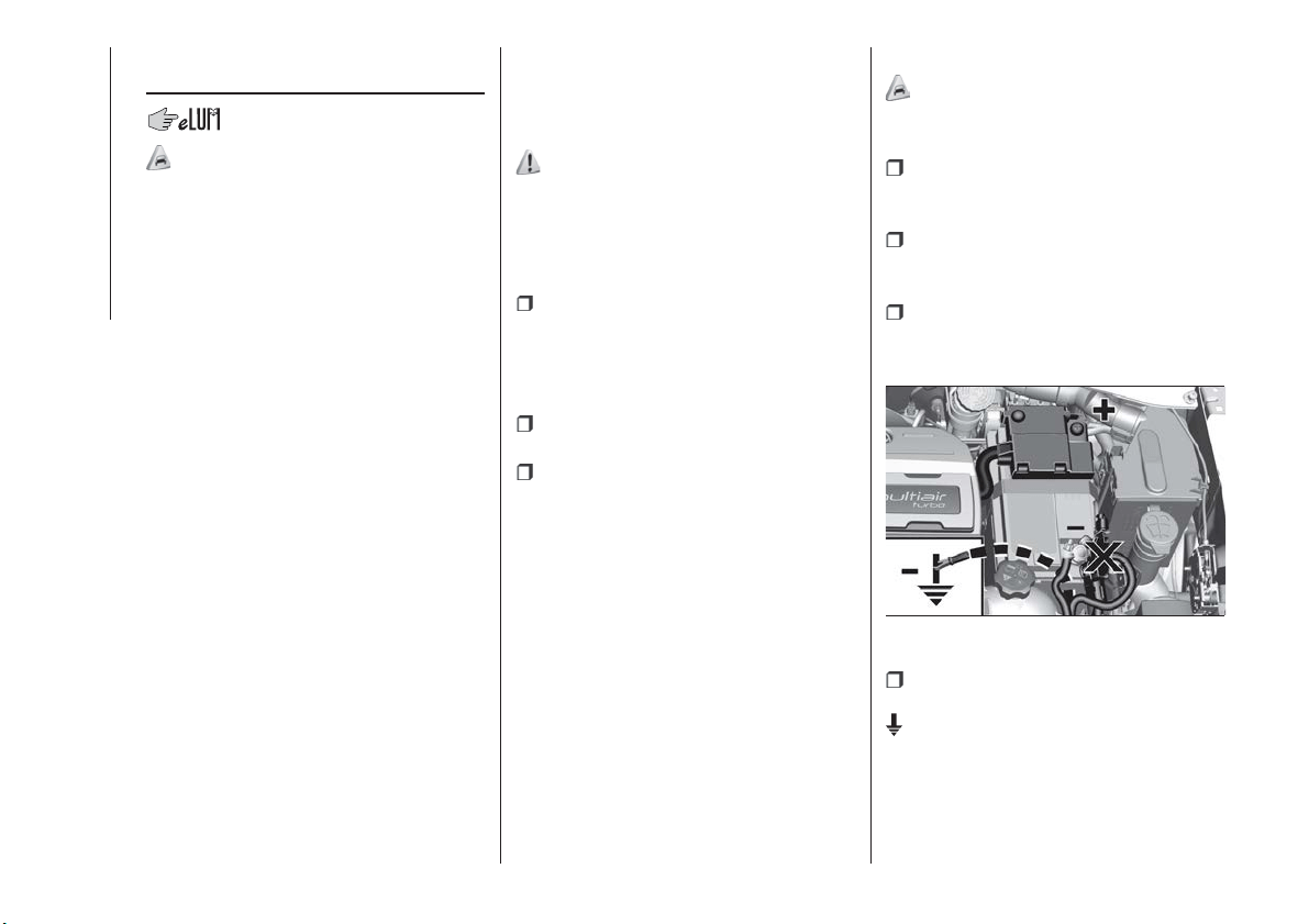
EMERGENCY
STARTING
81)
If the battery is flat, a jump starting can
be performed using the battery and the
cables of another vehicle, or using an
auxiliary battery. In all cases, the battery
used must have a capacity equal to or
a little higher than the flat one.
IMPORTANT
Do not use an auxiliary battery or any
other source of external supply with a
voltage above 12 V: the battery, the
starter, the alternator and the electrical
system of the vehicle could be
damaged.
Do not attempt jump starting if the
battery is frozen. The battery could
break and explode!
JUMP STARTING
The vehicle battery is located in the
engine compartment, behind the left
light cluster.
158) 159) 160) 161)
IMPORTANT The positive terminal (+) of
the battery is shielded by a protective
element. Raise it to access the terminal.
Proceed as follows:
operate the parking brake, move the
lever to P (Park), for versions equipped
with automatic transmission, or neutral,
for versions with manual gearbox, then
set the ignition device to STOP;
switch off all the other electrical
appliances in the vehicle;
should you be using the battery of
another vehicle, park the other vehicle
within the range of the cables used for
the connection, operate the parking
brake and ensure that its ignition is off.
IMPORTANT If the procedure below is
carried out incorrectly, it can cause
severe injury to people or damage the
recharging system of one or both
vehicles. Carefully follow the
instructions given below.
Cable connection
82)
Proceed as follows to carry out bump
starting fig. 148:
connect one end of the cable used
for positive (+) to the positive terminal
(+) of the vehicle with flat battery;
connect the other end of the cable
used for positive (+) to the positive
terminal (+) of the auxiliary battery;
connect one end of the cable used
for negative (–) to the negative terminal
(–) of the auxiliary battery;
Connect the other end of the cable
used for negative (–) to an engine earth
(a visible metal part of the engine or
gearbox/transmission of the vehicle
with flat battery) away from the battery
and the fuel injection system;
148
F1B0217C
166
IN AN EMERGENCY
start the vehicle engine with the
auxiliary battery, let it run for a few
minutes at idling. Start the engine of the
vehicle with flat battery.
Cable disconnection.
Once the engine is started, remove the
leads, reversing the order above.
If after a few attempts the engine does
not start, do not persist but contact a
Fiat Dealership.
If it is often necessary to perform an
emergency starting, have the vehicle
battery and the recharging system
checked by a Fiat Dealership.
IMPORTANT Any accessories (e.g.
mobile phones, etc.) connected to the
vehicle power sockets, draw current
even if they are not used. These
devices, if left connected too much time
with engine off, may cause the battery
to drain with following reduction of its
life and/or failure to start the engine.
WARNING
158) Before opening the bonnet, make
sure that the engine is off and that the
ignition key is in the STOP position. Follow
the indications on the plate underneath the
bonnet. We recommend that you remove
the key from the ignition if other people
remain in the vehicle. The vehicle should
always be left after the key has been
removed or turned to the STOP position.
During refuelling, make sure that the engine
is off (and that the ignition key is in the
STOP position).
159) Do not get too close to the radiator
cooling fan: the electric fan may start;
danger of injury. Scarves, ties and other
loose clothing might be pulled by moving
parts.
160) Remove any metal objects (e.g. rings,
watches, bracelets), that might cause an
accidental electrical contact and cause
serious injury.
161) The batteries contain acid that can
burn skin or eyes. Batteries produce
hydrogen, which is easily flammable and
explosive. Therefore, keep away flames or
devices which may cause sparks.
IMPORTANT
81) Never use a fast battery-charger to
start the engine as this could damage the
electronic systems of your vehicle,
particularly the ignition and engine fuel
supply control units.
82) Do not connect the cable to the
negative terminal (–) of the flat battery. The
following spark could lead to battery
explosion and cause serious harm. Only
use the specific earth point; do not use any
other exposed metallic part.
167
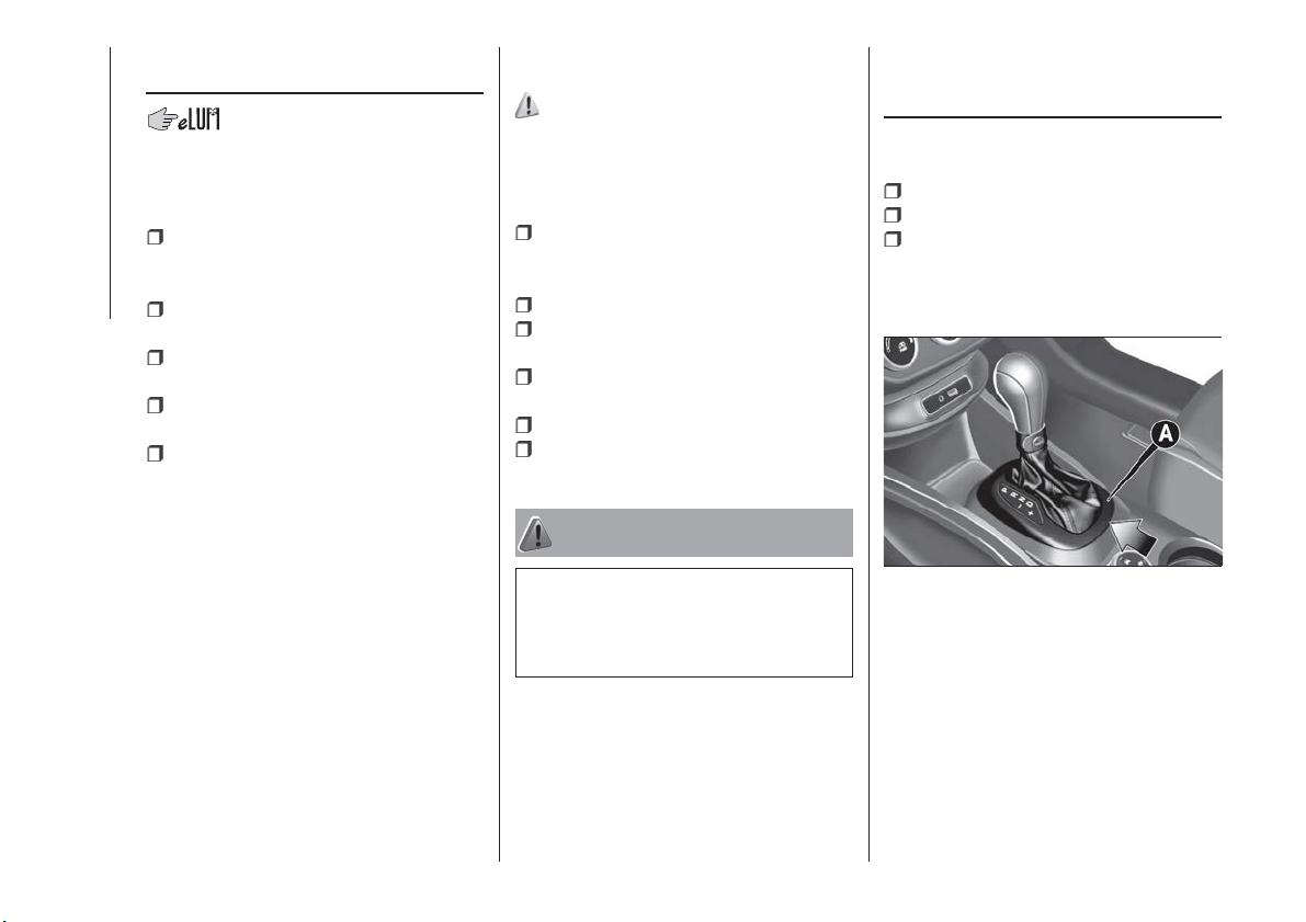
FUEL CUT-OFF
SYSTEM
DESCRIPTION
This intervenes in the case of an impact
causing:
the interruption of the fuel supply
with the engine consequently switching
off;
the automatic unlocking of the
doors;
turning on of the lights inside the
vehicle;
deactivation of climate control
system ventilation;
switching on of the hazard warning
lights (to deactivate the lights press the
button on the dashboard).
On some versions, the intervention of
the system is indicated by a message
shown on the display. In the same way,
a dedicated message on the display
warns the driver if system operation is
compromised.
IMPORTANT Carefully check the vehicle
for fuel leaks, for instance in the engine
compartment, under the vehicle or near
the tank area. After a collision, bring the
ignition device to STOP to prevent the
battery from running down.
FUEL CUT-OFF SYSTEM
RESET
162)
To restore correct operation of the car,
carry out the following procedure (this
procedure must be started and
completed within less than 1 minute):
with direction indicator lever in
neutral position, turn the ignition device
to STOP;
turn the ignition device to MAR;
activate the right direction indicator
and then the left one;
activate the right direction indicator
and then the left one again;
deactivate the left direction indicator;
turn the ignition device to STOP and
then to MAR.
WARNING
162) If, after an impact, you smell fuel or
notice leaks from the fuel system, do not
reactivate the system to avoid the risk of
fire.
AUTOMATIC
TRANSMISSION -
LEVER UNLOCK
In the event of a fault, to move the gear
lever from P (Park), proceed as follows:
stop the engine;
engage the electric parking brake;
working carefully in the point
indicated by the arrow, remove the trim
A fig. 149 (complete with gaiter) lifting it
upwards (see also fig. 150 );
149
F1B0028C
168
IN AN EMERGENCY
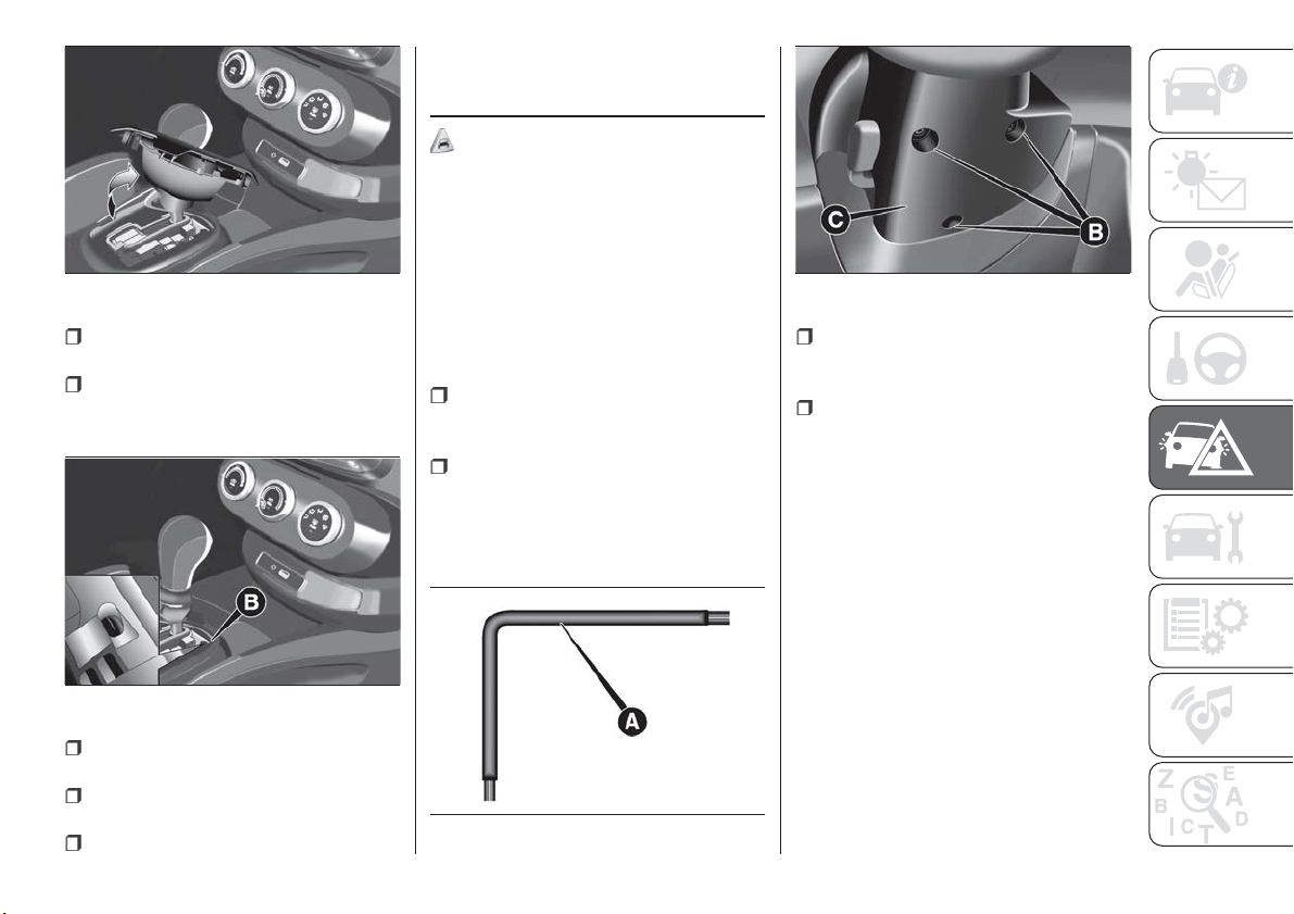
fully depress the brake pedal and
hold it down;
insert the screwdriver supplied
perpendicularly in hole B fig. 151 and
adjust the release lever;
place the gear lever in N (Neutral)
position;
refit the gear lever gaiter and trim
correctly;
start the engine.
AUTOMATIC
TRANSMISSION -
KEY REMOVAL
83)
The ignition key (for versions with key
without remote control) can be removed
only if the gear lever is in position P
(Park).
If the vehicle battery is flat and the
ignition key is engaged, the latter is
locked in position.
To remove the key manually, proceed
as follows:
stop the vehicle in safety conditions,
engage a gear and the electric parking
brake;
using the provided key A
fig. 152 (located in the casing
containing the on-board documents),
undo the fixing screws B fig. 153 for the
lower cover C;
remove the lower steering wheel
cover C fig. 153 by releasing it from its
housing;
pull tab D fig. 154 downwards using
one hand and with the other one
remove the key, sliding it outwards;
150
F1B0055C
151
F1B0056C
152
F1B0022C
153
F1B0143C
169
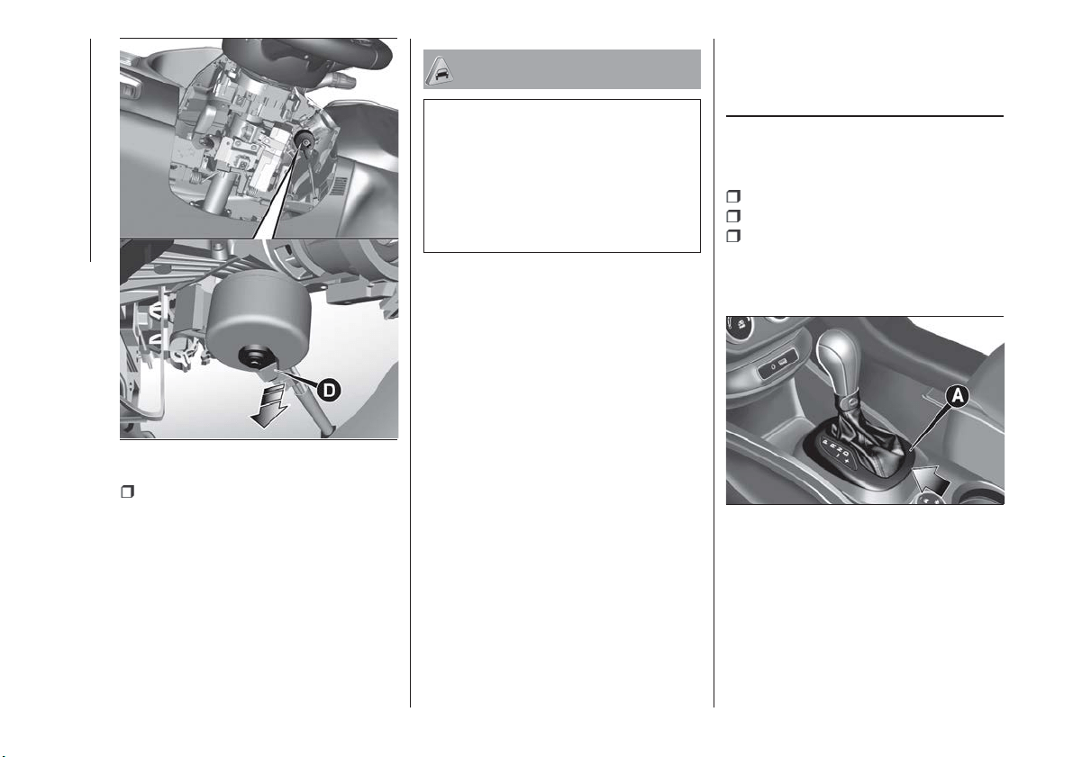
once the key has been removed,
refit lower cover C fig. 153, make sure it
locks correctly and tighten the fixing
screws B firmly.
IMPORTANT
83) It is advisable to contact a Fiat
Dealership to have the refitting procedure
carried out. If you would like to proceed
autonomously, special attention must be
paid to the correct coupling of the retaining
clips. Otherwise, noise might be heard due
to an incorrect fastening of the lower cover
with the upper cover.
DUAL CLUTCH
AUTOMATIC
TRANSMISSION -
LEVER UNLOCK
In case of failure or flat battery, to
unlock the gear lever, proceed as
follows:
stop the engine;
engage the electric parking brake;
working carefully in the point
indicated by the arrow, remove the trim
A fig. 155 (complete with gaiter) lifting it
upwards (see also fig. 156 );
154
F1B0222C
155
F1B0028C
170
IN AN EMERGENCY
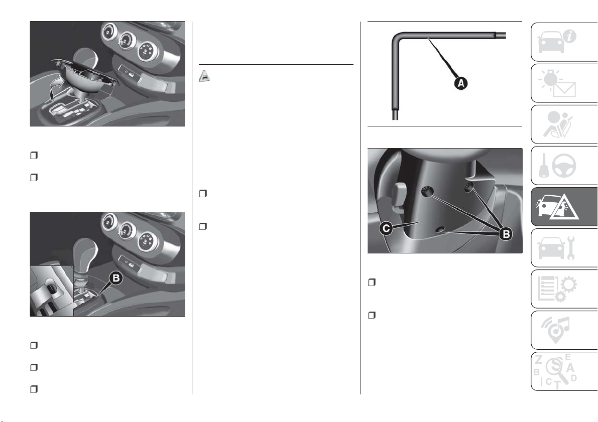
fully depress the brake pedal and
hold it down;
insert the screwdriver supplied
perpendicularly in hole B fig. 157 and
adjust the release lever;
place the gear lever in N (Neutral)
position;
refit the gear lever gaiter and trim
correctly;
start the engine.
DUAL CLUTCH
AUTOMATIC
TRANSMISSION -
REMOVING THE KEY
83)
The ignition key (for versions with key
without remote control) can be removed
only if the gear lever is in position P
(Park).
If the vehicle battery is flat and the
ignition key is engaged, the latter is
locked in position.
To remove the key manually, proceed
as follows:
stop the vehicle in safety conditions,
engage a gear and the electric parking
brake;
using the provided key A
fig. 158 (located in the casing
containing the on-board documents),
undo the fixing screws B fig. 159 for the
lower cover C;
remove the lower steering wheel
cover C fig. 159 by releasing it from its
housing;
pull tab D fig. 160 downwards using
one hand and with the other one
remove the key, sliding it outwards;
156
F1B0055C
157
F1B0056C
158
F1B0022C
159
F1B0143C
171
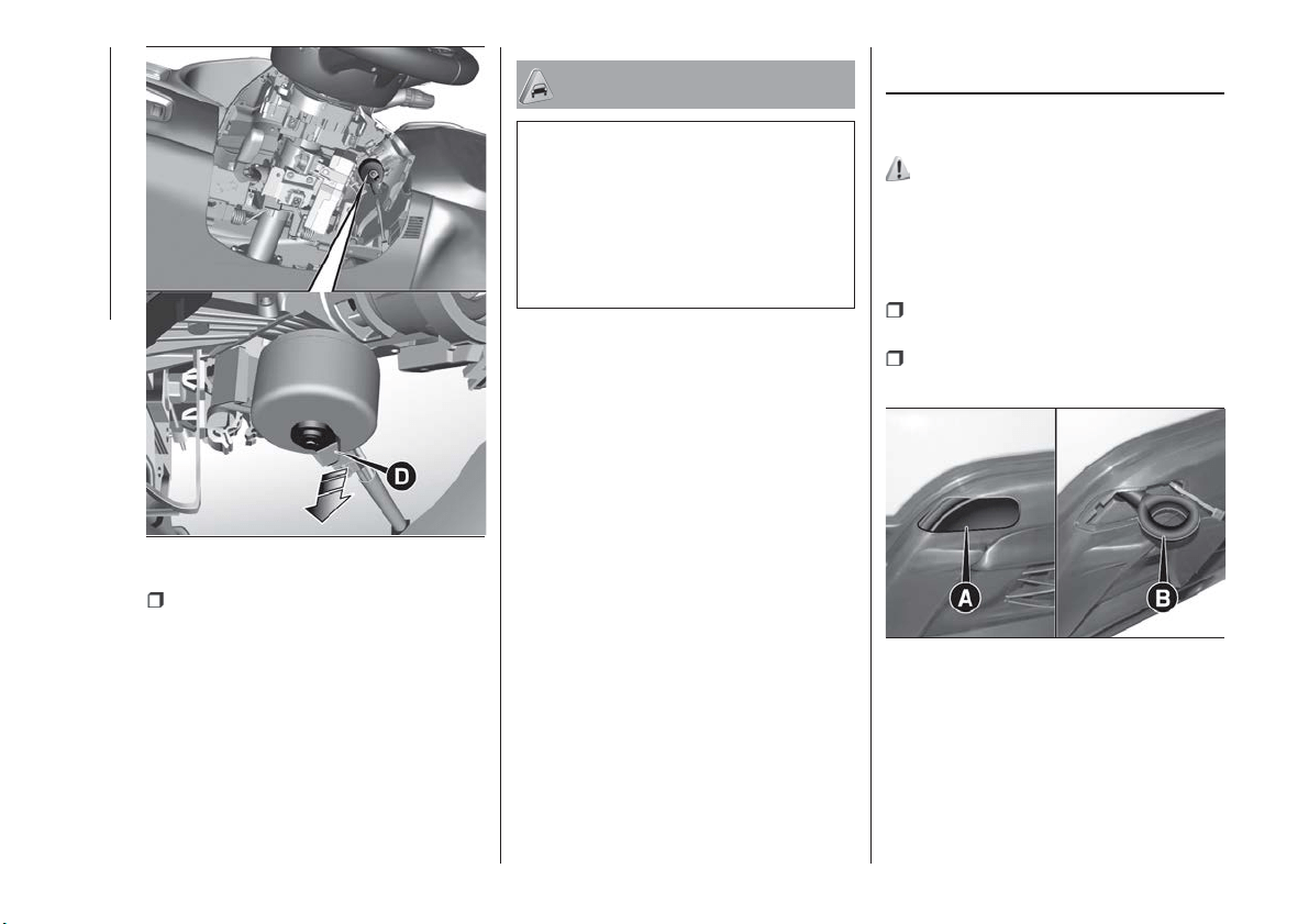
once the key has been removed,
refit lower cover C fig. 159, make sure it
locks correctly and tighten the fixing
screws B firmly.
IMPORTANT
84) It is advisable to contact a Fiat
Dealership to have the refitting procedure
carried out. If you would like to proceed
autonomously, special attention must be
paid to the correct coupling of the retaining
clips. Otherwise, noise might be heard due
to an incorrect fastening of the lower cover
with the upper cover.
TOWING THE
VEHICLE
ATTACHING THE TOW
HOOK
163) 164) 165)
The tow hook provided is located in the
tool box inside the boot.
Front
Proceed as follows:
release cap A fig. 161, operating in
the point shown by the arrow;
take tow hook B and screw it fully
onto the front threaded pin.
160
F1B0222C
161
F1B0196C
172
IN AN EMERGENCY
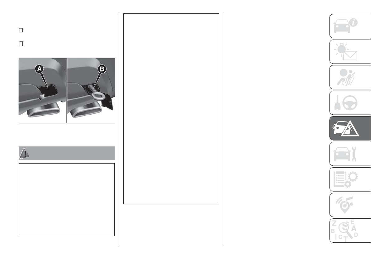
Rear
Proceed as follows:
release cap A fig. 162, operating in
the point shown by the arrow;
take tow hook B and screw it fully
onto the rear threaded pin
WARNING
163) For versions with key without remote
control, before towing, turn the ignition key
to MAR and then to STOP without
removing it. The steering column will
automatically lock when the key is removed
and the wheels cannot be steered. Also
check that the gearbox is in neutral (on
versions equipped with automatic
transmission, check that the gear lever is in
N position). For versions with electronic
key, move the ignition device to MAR and
then to STOP, without opening the door.
164) The brake servo and the
electromechanical power steering will not
work while the vehicle is being towed. You
will therefore need to apply more force on
the brake pedal and steering wheel. Do not
use flexible ropes when towing, and avoid
jerky movements. During towing, make
sure that the trailer hitch does not damage
any components it is touching. When
towing the car, you must comply with all
specific traffic regulations and adopt an
appropriate driving behaviour. Do not start
the engine while towing the car. Before
tightening the ring, clean the threaded
housing thoroughly. Make sure that the ring
is fully screwed into the housing before
towing the car.
165) The front and rear tow hooks should
be used only for emergencies on the road.
You are allowed to tow the vehicle for short
distances using an appropriate device in
accordance with the highway code (a rigid
bar), to move the vehicle on the road in
readiness for towing or transport via a
breakdown vehicle. Tow hooks MUST NOT
be used to tow vehicles off the road or
where there are obstacles and/or for
towing operations using cables or other
non-rigid devices. In compliance with the
above conditions, towing must take place
with the two vehicles (one towing, the other
towed) aligned as much as possible along
the same centre line.
162
F1B0197C
173

SERVICING AND MAINTENANCE
Correct maintenance permits the
performance of the vehicle to be
maintained over time, as well as limited
running costs and safeguarding the
efficiency of the safety systems.
This chapter explains how.
SCHEDULED SERVICING.......175
ENGINE COMPARTMENT ......187
BATTERY RECHARGING .......197
SERVICING PROCEDURES .....198
LIFTING THE VEHICLE.........201
WHEELS AND TYRES .........201
BODYWORK ...............203
INTERIORS ................204
174
SERVICING AND MAINTENANCE
SCHEDULED
SERVICING
Correct servicing is crucial for
guaranteeing a long life for the car
under the best conditions.
For this reason, Fiat has planned a
series of checks and services at fixed
distance and/or time intervals, as
described in the Service Schedule.
To keep the car’s efficiency in tip-top
condition, in the following Scheduled
Service plan pages a few additional
checks are listed that should be carried
out more frequently with respect to the
normal coupon redemption schedule.
Scheduled Servicing is offered by all
Fiat Dealerships according to fixed time
or kilometres/miles intervals. If, during
each operation, in addition to the ones
scheduled, the need arises for further
replacements or repairs, these may be
carried out with the owner's explicit
agreement only. If your car is used
frequently for towing, the interval
between one scheduled servicing
operation and the next should be
reduced.
IMPORTANT Scheduled Servicing
interventions are set out by the
Manufacturer. Failure to comply with the
schedule may invalidate the warranty.
We advise sharing any doubts
regarding the car’s proper operation
with your Fiat Dealership, before waiting
for the next coupon redemption.
175
SERVICE SCHEDULE (1.4 Turbo Multi Air, 1.4 T-Jet LPG and 2.4 Tigershark
versions)
WARNING: Once you have carried out the last intervention in the table, continue with the scheduled servicing, maintaining the
frequency indicated in the plan by marking each operation with a dot or dedicated note.
Warning: simply restarting the maintenance from the start of the plan may cause the allowed interval to be exceeded for some
operations!
Thousands of miles
9 182736455463728190
Thousands of kilometres
15 30 45 60 75 90 105 120 135 150
Years
12345678910
Check tyre condition/wear and adjust pressure, if
necessary. Check quick tyre repair kit recharge
conditions/expiry date (if provided)
●●●●●●●●●●
Check operation of lighting system (headlamps, direction
indicators, hazard warning lights, luggage compartment,
passenger compartment, instrument panel warning lights,
etc.)
●●●●●●●●●●
Check and, if necessary, top up fluid levels(1)
●●●●●●●●●●
Visually inspect condition of: LPG pipes and connectors,
LPG tank fixing (1.4 T-Jet LPG versions)
●●●●●
Check exhaust emissions
●●●●●●●●●●
Use the diagnosis socket to check the operation of the
engine management systems, emissions and, for
versions/markets where provided, engine oil degradation
●●●●●●●●●●
(1) Always only use the liquids shown in the handbook for topping up after having checked that the system is not damaged.
176
SERVICING AND MAINTENANCE
Thousands of miles
9 182736455463728190
Thousands of kilometres
15 30 45 60 75 90 105 120 135 150
Years
12345678910
Visually inspect conditions of: exterior bodywork,
underbody protection, pipes and hoses (exhaust, fuel
system, brakes), rubber elements (gaiters, sleeves,
bushes, etc.)
●●●●●
Check windscreen and rear window wiper blade
position/wear
●●●●●
Check operation of the windscreen wiper/washer system
and adjust jets, if necessary
●●●●●
Check cleanliness of bonnet and luggage compartment
locks, cleanliness and lubrication of linkage
●●●●●
Visually inspect conditions and wear of front and rear disc
brake pads and integrity of pad wear indicator
●●●●●●●●●●
Visually inspect condition of the accessory drive belt(s)(6)
●
Check tension of accessory drive belt (versions without
automatic tensioner)
●●
Visually inspect condition of toothed timing drive belt
(2.4 Tigershark excluded)(6)
●
Check pressure regulator and seal of the corresponding
heating pipes (1.4 T-Jet LPG versions)
●●●●●
(6) The maximum mileage is 120,000 km. The belt must be replaced every 6 years, regardless of distance travelled. If the vehicle is used in heavy conditions (dusty
areas, cold climates, urban driving, long periods of idling), the maximum mileage is 60,000 km. The belt must be replaced every 4 years regardless of the
mileage.
177
Thousands of miles
9 182736455463728190
Thousands of kilometres
15 30 45 60 75 90 105 120 135 150
Years
12345678910
Check correct fitting of injectors (positioning, clip retention)
(1.4 T-Jet LPG versions)
●●●●●
Check drive transmission idler unit (PTU) oil level
(4x4 versions)
●●
Check rear differential fluid level (4x4 versions)
●●
Check oil level of electro-hydraulic actuator and top up, if
necessary (1.4 Turbo Multi Air versions with dual-clutch
automatic transmission)(2)
●
Change engine oil and replace oil filter (1.4 Turbo Multi Air
and 1.4 T-Jet LPG versions)(3) (O) (●)
● ● ● ● ●
Change engine oil and oil filter (2.4 Tigershark versions)(4)
●●●●●●●●●●
Replace spark plugs (1.4 Turbo Multi Air and 1.4 T-Jet
LPG versions)(5)
●●●●●
Replace spark plugs (2.4 Tigershark versions)
●●●
(2) Check to be carried out every year for cars on the road in countries with particularly severe climates (cold countries).
(3) If the car's annual mileage is less than 10,000 km, the engine oil and filter must be replaced every year.
(O) Recommended operations
(●) Obligatory operations
(4) The engine oil and oil filter must be replaced when the warning light on the instrument panel switches on or, in any case, every year.
(5) For 1.4 Turbo MultiAir and 1.4 T-Jet LPG versions, to guarantee correct operation and prevent serious damage to the engine, it is essential to: only use spark
plugs specifically certified for these engines; all spark plugs should be of the same type and brand (see the "Engine" paragraph in the "Technical specifications"
chapter); strictly comply with the spark plugs replacement intervals on the Service Schedule. It is advisable to contact a FIAT Dealership for plug replacement.
178
SERVICING AND MAINTENANCE
Thousands of miles
9 182736455463728190
Thousands of kilometres
15 30 45 60 75 90 105 120 135 150
Years
12345678910
Replace accessory drive belt/s
(6)
Replace toothed timing drive belt (1.4 Turbo Multi Air and
1.4 T-Jet LPG versions only)
(6)
Change the brake fluid
(7)
Replace the filter inside the pressure regulator (1.4 T-Jet
LPG versions)
●
Replace the paper filter (LPG in gaseous state) (1.4 T-Jet
LPG versions)
●●●●●
Replace air cleaner cartridge(8)
●●●●●
Replace the passenger compartment cleaner(8) (O) (●)
● ● ● ● ●
(6) The maximum mileage is 120,000 km. The belt must be replaced every 6 years, regardless of distance travelled. If the vehicle is used in heavy conditions (dusty
areas, cold climates, urban driving, long periods of idling), the maximum mileage is 60,000 km. The belt must be replaced every 4 years regardless of the
mileage.
(7) Brake fluid is to be replaced every 2 years regardless of the distance travelled.
(8) If the vehicle is used in dusty areas, this cleaner must be replaced every 15,000 km.
(O) Recommended operations
(●) Obligatory operations
NOTE change automatic transmission oil and replace oil filter every 240,000 km.
179
SCHEDULED SERVICING PLAN (1.6 E.Torq versions)
WARNING: Once you have carried out the last intervention in the table, continue with the scheduled servicing, maintaining the
frequency indicated in the plan by marking each operation with a dot or dedicated note.
Warning: simply restarting the maintenance from the start of the plan may cause the allowed interval to be exceeded for some
operations!
Thousands of miles
9 182736455463728190
Thousands of kilometres
15 30 45 60 75 90 105 120 135 150
Years
12345678910
Check tyre condition/wear and adjust pressure, if
necessary. Check quick tyre repair kit recharge
conditions/expiry date (if provided)
●●●●●●●●●●
Check operation of lighting system (headlamps, direction
indicators, hazard warning lights, luggage compartment,
passenger compartment, instrument panel warning lights,
etc.)
●●●●●●●●●●
Check and, if necessary, top up fluid levels(1)
●●●●●●●●●●
Check exhaust emissions
●●●●●●●●●●
Use the diagnosis socket to check the operation of the
engine management systems, emissions and, for
versions/markets where provided, engine oil degradation
●●●●●●●●●●
Visually inspect conditions of: exterior bodywork,
underbody protection, pipes and hoses (exhaust, fuel
system, brakes), rubber elements (gaiters, sleeves,
bushes, etc.)
●●●●●
(1) Always only use the liquids shown in the handbook for topping up after having checked that the system is not damaged.
180
SERVICING AND MAINTENANCE
Thousands of miles
9 182736455463728190
Thousands of kilometres
15 30 45 60 75 90 105 120 135 150
Years
12345678910
Check windscreen and rear window wiper blade
position/wear
●●●●●
Check operation of the windscreen wiper/washer system
and adjust jets, if necessary
●●●●●
Check cleanliness of bonnet and luggage compartment
locks, cleanliness and lubrication of linkage
●●●●●
Visually inspect conditions and wear of front and rear disc
brake pads and integrity of pad wear indicator
●●●●●●●●●●
Visually inspect condition of the accessory drive belt(s)
●●●●●●●●●●
Check tension of accessory drive belt (versions without
automatic tensioner)
●●●●●●●●●●
Change engine oil and replace oil filter
●●●●●●●●●●
Spark plug replacement
●●●●●
Replace accessory drive belt/s
●
Replace air cleaner cartridge(2)
●●●●●
Change the brake fluid
(3)
(2) If the vehicle is used in dusty areas, this cleaner must be replaced every 15,000 km.
(3) The brake fluid replacement has to be done every 2 years, irrespective of the mileage.
181
Thousands of miles
9 182736455463728190
Thousands of kilometres
15 30 45 60 75 90 105 120 135 150
Years
12345678910
Replace the passenger compartment cleaner(2) (O) (●)
● ● ● ● ●
(2) If the vehicle is used in dusty areas, this cleaner must be replaced every 15,000 km.
(O) Recommended operations
(●) Obligatory operations
182
SERVICING AND MAINTENANCE
SCHEDULED SERVICING PLAN (Diesel versions)
WARNING: Once you have carried out the last intervention in the table, continue with the scheduled servicing, maintaining the
frequency indicated in the plan by marking each operation with a dot or dedicated note.
Warning: simply restarting the maintenance from the start of the plan may cause the allowed interval to be exceeded for some
operations!
Thousands of miles
12 24 36 48 60 72 84 96 108 120
Thousands of kilometres
20 40 60 80 100 120 140 160 180 200
Years
12345678910
Check tyre condition/wear and adjust pressure, if
necessary. Check quick tyre repair kit recharge
conditions/expiry date (if provided)
●●●●●●●●●●
Check operation of lighting system (headlamps, direction
indicators, hazard warning lights, luggage compartment,
passenger compartment, instrument panel warning lights,
etc.)
●●●●●●●●●●
Check and, if necessary, top up fluid levels(1)
●●●●●●●●●●
Check exhaust emissions
●●●●●●●●●●
Use the diagnosis socket to check supply/engine
management systems operation, emissions and, for
versions/markets, where provided, engine oil degradation
●●●●●●●●●●
Visually inspect conditions of: exterior bodywork,
underbody protection, pipes and hoses (exhaust, fuel
system, brakes), rubber elements (gaiters, sleeves,
bushes, etc.)
●●●●●
(1) Always only use the liquids shown in the handbook for topping up after having checked that the system is not damaged.
183
Thousands of miles
12 24 36 48 60 72 84 96 108 120
Thousands of kilometres
20 40 60 80 100 120 140 160 180 200
Years
12345678910
Check windscreen and rear window wiper blade
position/wear
●●●●●
Check operation of the windscreen wiper/washer system
and adjust jets, if necessary
●●●●●
Check cleanliness of bonnet and luggage compartment
locks, cleanliness and lubrication of linkage
●●●●●
Visually inspect conditions and wear of front and rear disc
brake pads and integrity of pad wear indicator
●●●●●●●●●●
Visually inspect condition of the accessory drive belt(s)(4)
●●
Check tension of accessory drive belt (versions without
automatic tensioner)
●●
Visually inspect condition of toothed timing drive belt
(excluding 1.3 Multijet 16V version)(4)
●●
Check drive transmission idler unit (PTU) oil level (except
2.0 Multijet 4x4 versions)
●●
Check oil level of electro-hydraulic actuator and top up, if
necessary (1.6 Multijet versions with dual-clutch automatic
transmission)(2)
●
Check rear differential fluid level (2.0 Multijet 4x4 versions)
●●
(4) The maximum mileage is 120,000 km. The belt must be replaced every 6 years, regardless of distance travelled. If the vehicle is used in heavy conditions (dusty
areas, cold climates, urban driving, long periods of idling), the maximum mileage is 60,000 km. The belt must be replaced every 4 years regardless of the
mileage.
(2) Check to be carried out every year for cars on the road in countries with particularly severe climates (cold countries).
184
SERVICING AND MAINTENANCE
Thousands of miles
12 24 36 48 60 72 84 96 108 120
Thousands of kilometres
20 40 60 80 100 120 140 160 180 200
Years
12345678910
Change engine oil and replace oil filter
(3)
Replace accessory drive belt/s
(4)
Replace toothed timing drive belt (excluding 1.3 Multijet
16V versions)
(4)
Replace fuel filter cartridge(5)
●●●
Replace air cleaner cartridge(6)
●●●●●
Change the brake fluid
(7)
Replace the passenger compartment cleaner(6) (O) (●)
● ● ● ● ●
(3) The actual interval for changing engine oil and replacing the engine oil filter depends on the vehicle usage conditions and is signalled by the warning light or
message in the instrument panel. In any case, it must never exceed 2 years. Where the car is used mostly in urban settings you need to replace the engine oil
filter every year.
(4) The maximum mileage is 120,000 km. The belt must be replaced every 6 years, regardless of distance travelled. If the vehicle is used in heavy conditions (dusty
areas, cold climates, urban driving, long periods of idling), the maximum mileage is 60,000 km. The belt must be replaced every 4 years regardless of the
mileage.
(5) If the car runs on fuel with quality below the relevant European specification, this filter should be replaced every 20,000 km
(6) If the vehicle is used in dusty areas, this cleaner must be replaced every 20,000 km.
(7) The brake fluid replacement has to be done every two years, irrespective of the mileage.
(O) Recommended operations
(●) Obligatory operations
NOTE change automatic transmission oil and replace oil filter every 240,000 km.
185

PERIODIC CHECKS
Every 1,000 km or before long trips
check and, if necessary, top up:
engine coolant level;
brake fluid level;
windscreen washer fluid level;
tyre inflation pressure and condition;
operation of lighting system
(headlights, direction indicators, hazard
warning lights, etc.);
operation of screen washer/wiper
system and positioning/wear of
windscreen/rear window wiper blades.
Every 3,000 km, check and top up if
required: engine oil level.
DEMANDING USE OF THE
CAR
If the car is used mainly under one of
the following conditions:
law enforcement (or security service),
taxi service;
towing a trailer or caravan;
dusty roads;
short, repeated journeys (less than
7-8 km) at sub-zero outside
temperatures;
engine often idling or driving long
distances at low speeds or long periods
of inactivity;
the following checks must be carried
out more often than indicated in the
Service Schedule:
check front disc brake pad condition
and wear;
check cleanliness of bonnet and
luggage compartment locks,
cleanliness and lubrication of linkage;
visually inspect conditions of: engine,
gearbox, transmission, pipes and hoses
(exhaust/fuel system/brakes) and
rubber elements (gaiters/sleeves/
bushes, etc.);
check battery charge and battery
fluid level (electrolyte);
visually inspect conditions of the
accessory drive belts;
check and, if necessary, change
engine oil and replace oil filter;
check and, if necessary, replace
pollen filter;
check and, if necessary, replace air
cleaner.
186
SERVICING AND MAINTENANCE
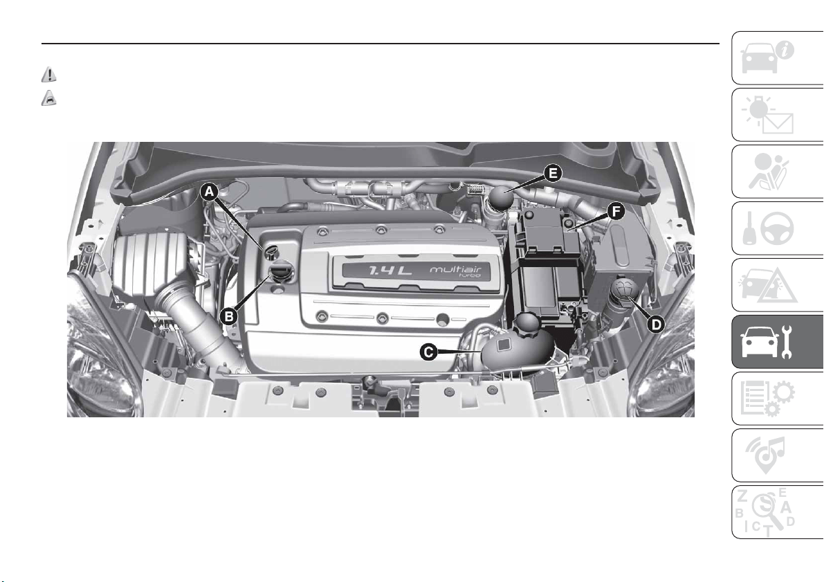
ENGINE COMPARTMENT
CHECKING LEVELS
166) 167)
85)
1.4 Turbo MultiAir versions
A - Engine oil level dipstick-B-Engine oil Cap/Filler-C-Engine coolant-D-Windscreen/rear window washer - E - Brake
fluid-F-Battery
163
F1B0171C
187
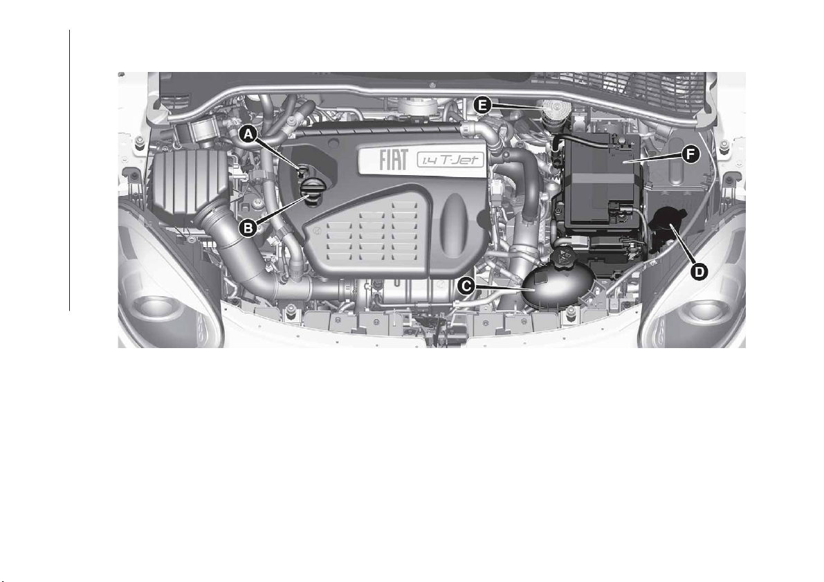
1.4 T–Jet LPG versions
A - Engine oil level dipstick/B-Engine oil Cap/Filler/C-Engine coolant/D-Windscreen/rear window washer/E-Brake
fluid/F-Battery
164
F1B0346C
188
SERVICING AND MAINTENANCE
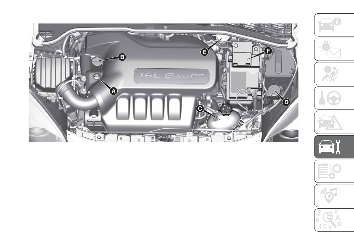
1.6 E.Torq versions
A - Engine oil level dipstick-B-Engine oil Cap/Filler-C-Engine coolant-D-Windscreen/rear window washer - E - Brake
fluid-F-Battery
165
F1B0234C
189
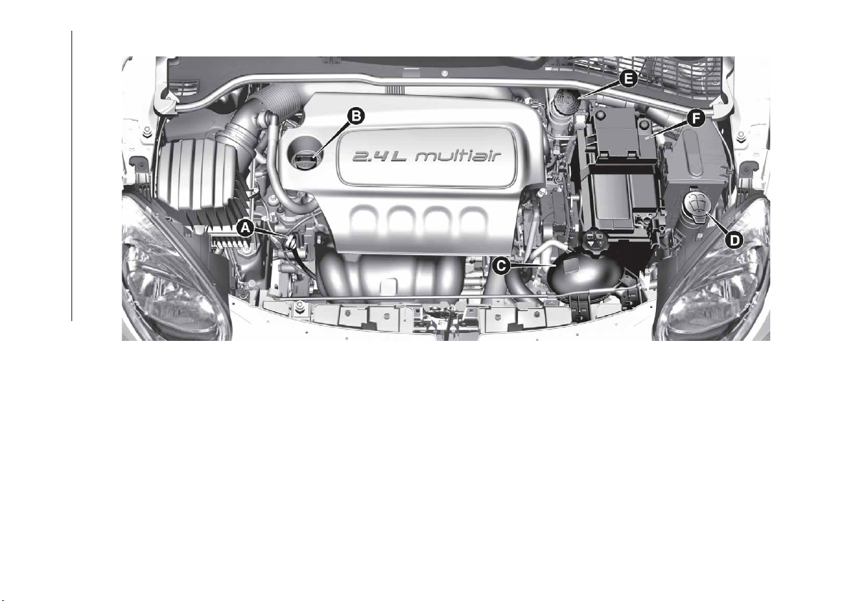
2.4 Tigershark version (where provided)
A - Engine oil level dipstick-B-Engine oil Cap/Filler-C-Engine coolant-D-Windscreen/rear window washer - E - Brake
fluid-F-Battery
166
F1B0399C
190
SERVICING AND MAINTENANCE
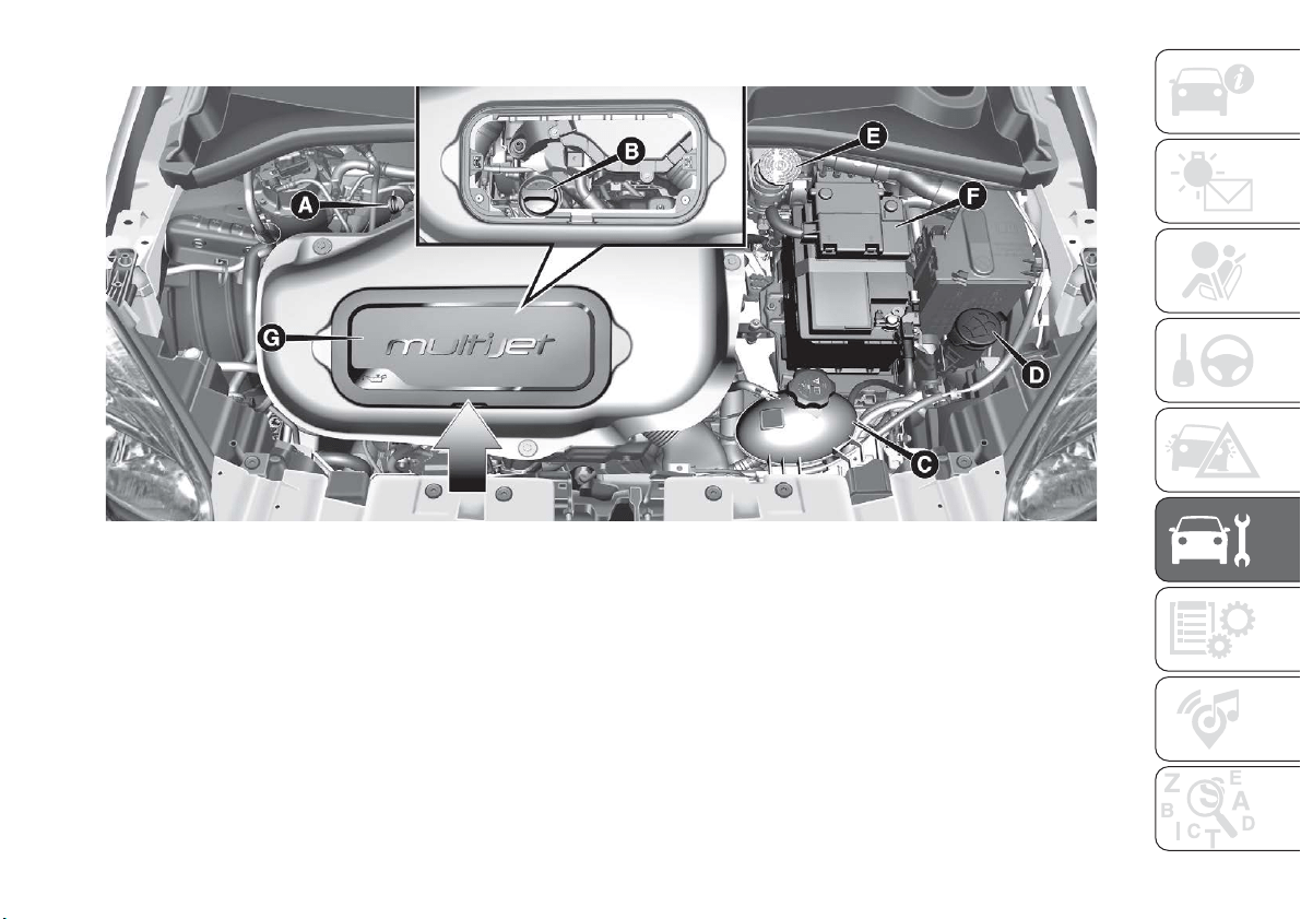
1.3 16V MultiJet version
A - Engine oil level dipstick-B-Engine oil Cap/Filler-C-Engine coolant-D-Windscreen/rear window washer - E - Brake
fluid-F-Battery
NOTE To access the engine oil cap/filler B, remove the cover G by operating on the point indicated by the arrow.
167
F1B0239C
191
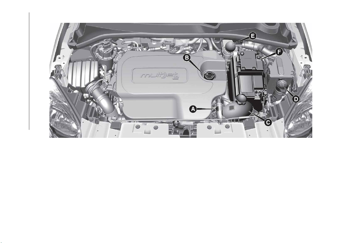
1.6 16V MultiJet version
A - Engine oil level dipstick-B-Engine oil Cap/Filler-C-Engine coolant-D-Windscreen/rear window washer - E - Brake
fluid-F-Battery
168
F1B0172C
192
SERVICING AND MAINTENANCE
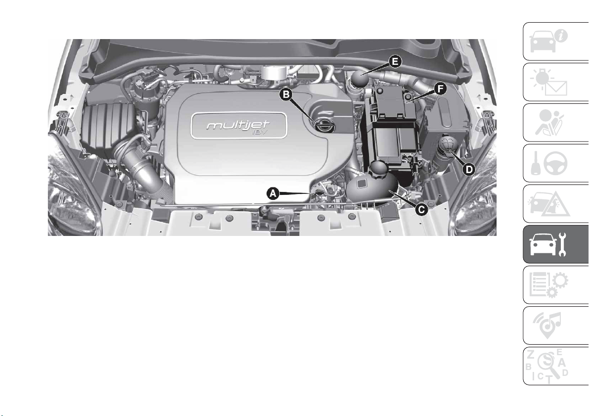
2.0 16V MultiJet version
A - Engine oil level dipstick-B-Engine oil Cap/Filler-C-Engine coolant-D-Windscreen/rear window washer - E - Brake
fluid-F-Battery
169
F1B0173C
193

ENGINE OIL
168)
86)
Check the oil level a few minutes (about
5) after the engine has stopped, with
the vehicle parked on level ground.
Check that the oil level is between the
MIN and MAX references on the
dipstick A.
If the oil level is near or under the MIN
reference, add oil through the filler B
until it reaches the MAX reference.
Take out the engine oil dipstick A, clean
it with a lint-free cloth and reinsert it.
Extract it again and check that the level
is between the MIN and MAX marks on
the dipstick.
Engine oil consumption
87)
3)
The maximum engine oil consumption
is usually 400 grams every 1,000 km.
When the vehicle is new, the engine
needs to be run in; therefore the engine
oil consumption can only be considered
stabilised after the first 5,000 -
6,000 km.
IMPORTANT After adding or changing
the oil, let the engine turn over for a few
seconds and wait a few minutes after
turning it off before you check the level.
ENGINE COOLANT
169)
88)
If the level is too low, unscrew the cap
of reservoir C and add the fluid
described in the "Technical
Specifications" chapter.
WINDSCREEN/REAR
WINDOW WASHER FLUID
170) 171)
If the level is too low, lift reservoir cap D
and add the fluid described in the
chapter "Technical Specifications".
IMPORTANT The headlight washer
system (present) will not operate when
the fluid level is low, even though the
windscreen/rear window washer
continues to operate.
BRAKE FLUID
172) 173)
89)
Check that the fluid is at the max. level.
If the fluid level in the reservoir is too
low, undo reservoir cap E and add the
fluid described in the chapter "Technical
Specifications".
IMPORTANT Carefully clean the cap of
the reservoir and the surrounding
surface. Take great care to ensure that
impurities do not enter the reservoir
when the cap is opened.
For topping-up, always use a funnel
with integrated filter with mesh equal to
or lower than 0.12 mm.
IMPORTANT Brake fluid is hygroscopic
(i.e. it absorbs moisture). For this
reason, if the vehicle is mainly used in
areas with a high degree of
atmospheric humidity, the fluid should
be replaced at more frequent intervals
than specified in the "Scheduled
Servicing Plan".
194
SERVICING AND MAINTENANCE
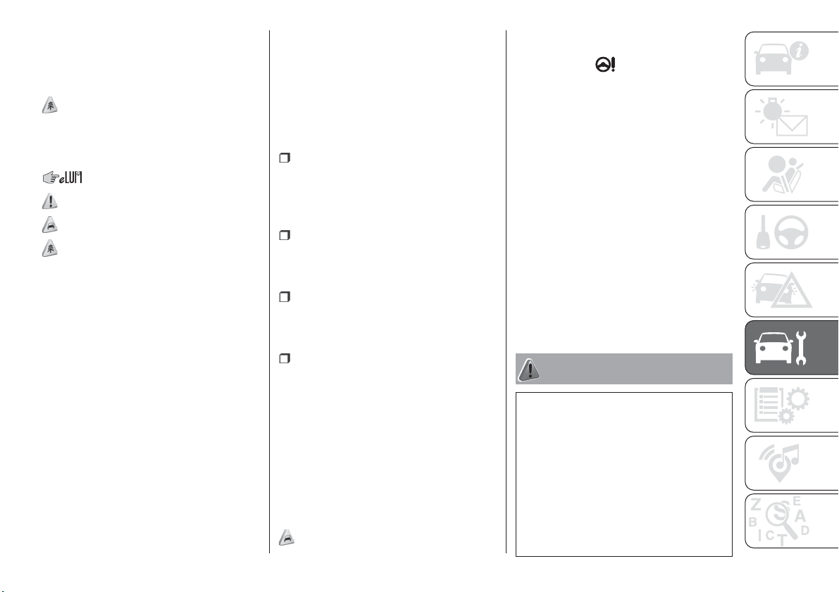
AUTOMATIC
TRANSMISSION / TWIN
CLUTCH AUTOMATIC
TRANSMISSION
ACTUATION SYSTEM OIL
4)
The transmission control oil level should
only be checked at a Fiat Dealership.
BATTERY
174) 175) 176)
90)
5)
The battery does not require the
electrolyte to be topped up with distilled
water.
A periodic check carried out at a Fiat
Dealership is, however, necessary to
check efficiency.
Replacing the battery
If necessary, replace the battery with
another original battery with the same
specifications. Follow the battery
Manufacturer’s instructions for
maintenance.
USEFUL ADVICE FOR
EXTENDING THE LIFE OF
YOUR BATTERY
Useful advice for extending the life
of your battery
To avoid draining your battery and
make it last longer, observe the
following instructions:
when you park the vehicle, ensure
that the doors, tailgate and bonnet are
closed properly, to prevent any lights
from remaining on inside the passenger
compartment;
switch off all roof lights inside the
vehicle: the vehicle is however
equipped with a system which switches
all interior lights off automatically;
do not keep accessories (e.g. radio,
hazard warning lights, etc.) switched on
for a long time when the engine is not
running;
before performing any operation on
the electrical system, disconnect the
negative battery cable.
If, after purchasing the vehicle, you wish
to install electrical accessories which
require permanent electrical supply (e.g.
alarm, etc.) or accessories which
influence the electrical supply
requirements, contact a Fiat Dealership,
whose qualified staff will evaluate the
overall electrical consumption.
91)
IMPORTANT After the battery is
disconnected, the steering must be
initialised. The
warning light on the
instrument panel (or symbol on the
display) switches on to indicate this. To
carry out this procedure, simply turn the
steering wheel all the way from one end
to the other or drive in a straight line for
about a hundred metres.
IMPORTANT If the charge level remains
under 50% for a long time, the battery
is damaged by sulphation, reducing its
capacity and efficiency at start-up. The
battery is also more prone to the risk of
freezing (at temperatures of -10°C).
Refer to the "Vehicle inactivity"
paragraph in "Starting and driving"
chapter if the vehicle is left parked for a
long time.
WARNING
166) Never smoke while working in the
engine compartment: gas and inflammable
vapours may be present, with the risk of
fire.
167) Be very careful when working in the
engine compartment when the engine is
hot: you may get burned.
168) If the engine oil is being topped up,
wait for the engine to cool down before
loosening the filler cap, particularly for
vehicles with aluminium cap (where
provided). WARNING: risk of burns!
195
169) The cooling system is pressurised. If
the cap needs replacing, do so with
another original or the effectiveness of the
system may be compromised. Do not
remove the reservoir plug when the engine
is hot: you risk scalding yourself.
170) Do not travel if the windscreen
washer reservoir is empty: using the
windscreen washer is essential for
improving visibility. Repeated operation of
the system without fluid could damage or
cause rapid deterioration of some system
components.
171) Some commercial additives for
windscreen washer fluid are flammable.
The engine compartment contains hot
components which may start a fire.
172) Brake fluid is poisonous and highly
corrosive. In the event of accidental
contact, immediately wash the affected
parts with water and mild soap. Then rinse
thoroughly. Call a doctor immediately if
swallowed.
173) The symbol
, on the brake fluid
container indicates if a brake fluid is
synthetic or mineral-based. Use of mineral
type fluids will damage the special rubber
seals of the braking system beyond repair.
174) Battery fluid is poisonous and
corrosive. Avoid contact with the skin and
eyes. Keep open flames away from the
battery and do not use objects that might
create sparks: risk of explosion and fire.
175) Using the battery with insufficient fluid
irreparably damages the battery and may
cause an explosion.
176) When performing any operation on
the battery or near it, always protect your
eyes with special goggles.
IMPORTANT
85) Be careful not to confuse the various
types of fluids while topping up: they are
not compatible with each other! Topping up
with an unsuitable fluid could severely
damage your vehicle.
86) The oil level must never exceed the
MAX. mark.
87) Always top up using engine oil of the
same specifications as that already in the
engine.
88) PARAFLU
UP
anti-freeze is used in the
engine cooling system. Use fluid of the
same type as that contained in the cooling
system for any top-ups. PARAFLU
UP
cannot be mixed with any other type of
fluid. If this happens, do not start the
engine under any circumstances and
contact a Fiat Dealership.
89) Prevent brake fluid, which is highly
corrosive, from coming into contact with
painted parts. Should it happen,
immediately wash with water.
90) If the vehicle must remain unused for a
long time at a very low temperature,
remove the battery and take it to a warm
place, to avoid freezing.
91) Incorrect installation of electric and
electronic devices may cause severe
damage to your car. After purchasing your
vehicle, if you wish to install any
accessories (e.g. anti-theft, radio phone,
etc.), go to a Fiat Dealership, which will
suggest the most suitable devices and
advise you whether a higher capacity
battery needs to be installed.
IMPORTANT
3) The used engine oil and the filter that has
been replaced contain substances that are
harmful to the environment. To change the
oil and filters, we advise you to contact a
Fiat Dealership.
4) Used transmission fluid contains
substances that are harmful to the
environment. It is advisable to contact a
Fiat Dealership to have the fluid changed.
5) Batteries contain substances which are
very dangerous for the environment. For
battery replacement, contact a Fiat
Dealership.
196
SERVICING AND MAINTENANCE
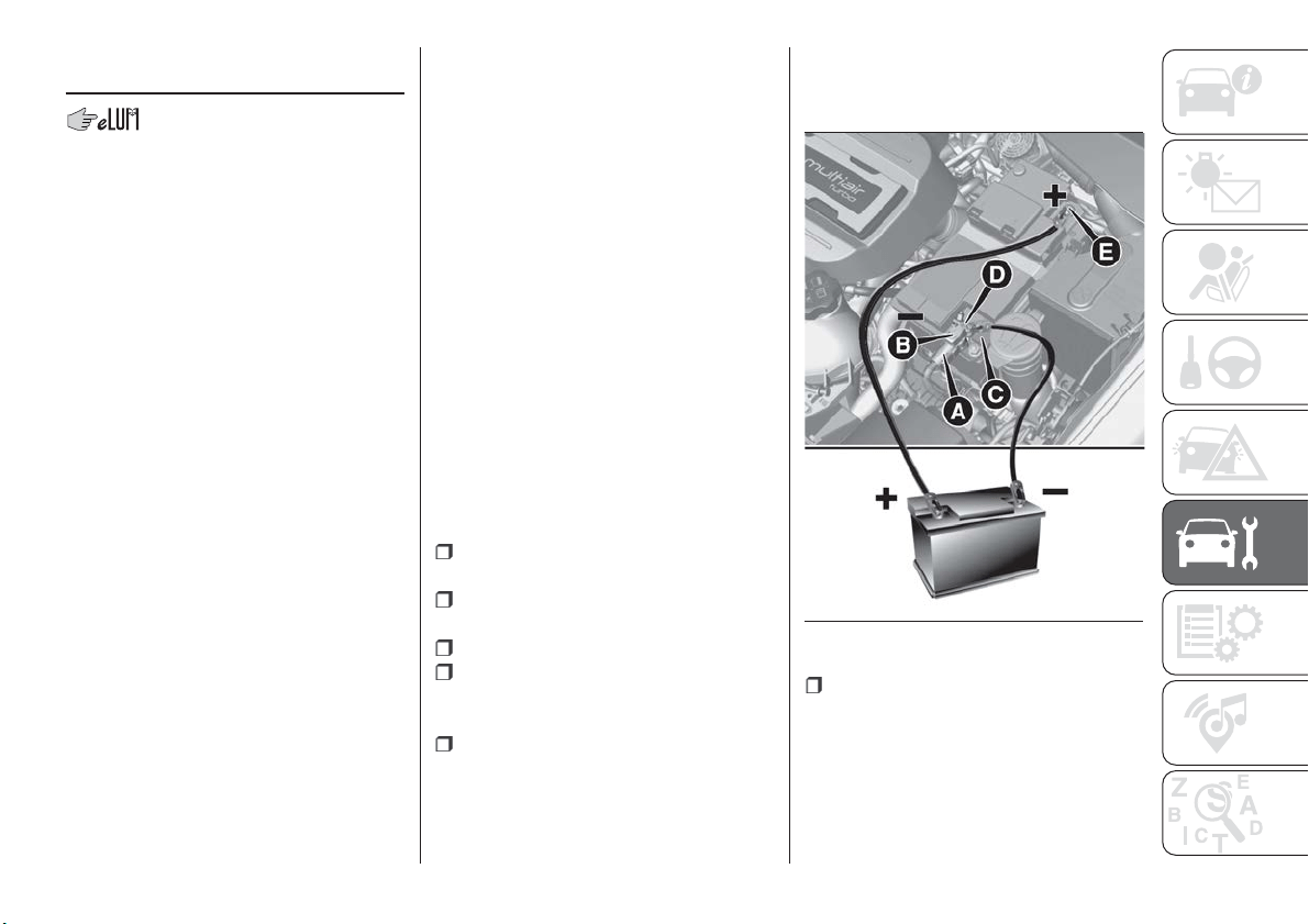
BATTERY
RECHARGING
IMPORTANT
IMPORTANT The battery recharging
procedure is given as information only.
To carry out this operation contact a
Fiat Dealership.
IMPORTANT After setting the ignition
device to STOP and having closed the
driver side door, wait at least one
minute before disconnecting the
electrical supply from the battery. When
reconnecting the electrical supply to the
battery, make sure that the ignition
device is in the STOP position and the
driver side door is closed.
IMPORTANT Charging should be slow
at a low ampere rating for
approximately 24 hours. Charging for a
longer time may damage the battery.
IMPORTANT The cables of the
electrical system must be correctly
reconnected to the battery, i.e. the
positive cable (+) to the positive
terminal and the negative cable (–) to
the negative terminal. The battery
terminals are marked with the positive
(+) and negative (–) symbols, and are
shown on the battery cover. The battery
terminals must also be corrosion-free
and firmly secured to the terminals. If a
"quick-type" battery charger is used
with the battery fitted on the vehicle,
before connecting it disconnect both
cables of the battery itself. Do not use a
"quick-type" battery charger to provide
the starting voltage.
VERSIONS WITHOUT
START&STOP SYSTEM
To recharge, proceed as follows:
disconnect the terminal from the
negative battery pole;
connect the charger cables to the
battery terminals, observing the polarity;
turn on the charger;
when it is recharged, turn the
charger off before disconnecting it from
the battery;
reconnect the negative battery
terminal.
VERSIONS WITH
START&STOP SYSTEM
To recharge, proceed as follows:
disconnect the connector A
fig. 170 (pressing the button B) from the
sensor C monitoring the battery
conditions, on the negative pole (–) D of
the battery;
170
F1B0300C
197
connect the positive cable (+) of the
battery charger to the positive battery
terminal E and the negative cable (–) to
sensor terminal D as shown;
turn on the battery charger. At the
end of the charging process, switch the
battery charger off;
after having disconnected the
charging device, reconnect connector A
to the sensor C as shown.
SERVICING
PROCEDURES
92) 93) 94)
The following pages contain the rules
on the required maintenance
envisaged by the technical personnel
who designed the vehicle.
In addition to these specific
maintenance instructions specified for
routine scheduled servicing, there are
other components which may require
intervention or replacements over the
vehicle’s life cycle.
ENGINE OIL
95)
Engine oil level check
To ensure correct engine lubrication, the
oil must always be kept at the
prescribed level (see "Engine
compartment" in this chapter).
AIR CLEANER
177)
Replacing the air cleaner
See the "Scheduled servicing plan" for
the correct servicing intervals.
It is advisable to replace it with a
genuine spare part, designed especially
for this vehicle.
AIR CONDITIONING
SYSTEM MAINTENANCE
96) 97)
To ensure the best possible
performance, the air conditioning
system must be checked and undergo
maintenance at a Fiat Dealership at the
beginning of the summer.
WINDOWS
When cleaning the heated windscreen
and rear window be careful, if the
defrosting function is active, regarding
the temperature of the glass; also make
sure that children do not come into
contact with the heated surface. The
glass may be hot.
Never use an abrasive detergent to
clean the surface of the windows.
Do not use scrapers or sharp items that
might scratch the windows.
Spray the detergent on the cloth to be
used for cleaning the rear view mirror.
Do not spray the detergent directly on
the glass.
Cleaning the window with hot water
could cause the removal of any labels.
198
SERVICING AND MAINTENANCE
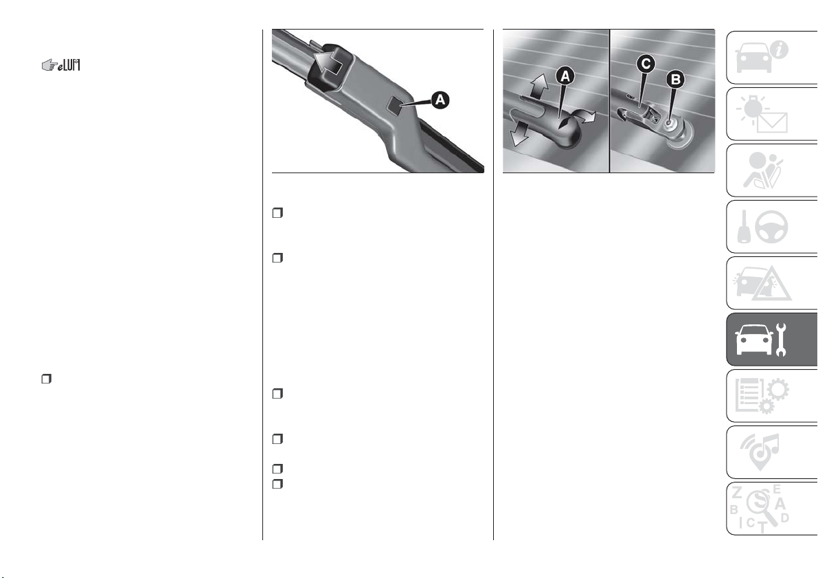
WINDSCREEN / REAR
WINDOW WIPERS
Raising the windscreen wipers
If you need to lift the windscreen wiper
blades (e.g. in case of snow or when
they need to be replaced), you need to
activate the "Service Position" function
(see paragraph "Windscreen/Rear
window wiper" in the "Knowing your
vehicle" chapter).
To lower the blades, set the ignition
device to MAR-ON.
IMPORTANT Place the blades back in
contact with the windscreen before
activating the windscreen wiper again
and/or setting the ignition device to
MAR-ON.
Replacing the windscreen wiper
blades
Proceed as follows:
raise the wiper arm, press button A
fig. 171 of the attachment spring and
remove the blade from the arm;
fit the new blade, inserting the tab in
the dedicated housing in the arm and
checking that it is locked;
lower the wiper arm on the
windscreen.
IMPORTANT Do not operate the
windscreen wiper with the blades lifted
from the windscreen.
Replacing the rear window wiper
blade
Proceed as follows:
widen the two tabs as shown by the
arrows and rotate cover A
fig. 172 outwards;
undo nut B and remove arm C from
the central pin;
correctly align the new arm;
fully tighten nut B and then refit
cover A.
IMPORTANT Do not operate the rear
window wiper with the blade lifted from
the rear window.
NOZZLES
Windscreen washer
The window washer nozzles are fixed. If
there is no jet of fluid, firstly check that
there is fluid in the reservoir (see
paragraph “Engine compartment” in
this chapter). Then check that the
nozzle holes are not clogged; use a
needle to unblock them if necessary.
IMPORTANT In versions with sun roof,
make sure that the roof is closed before
operating the windscreen washer
nozzles.
Rear window washer
The rear window washer nozzle is fixed.
The jet nozzle is located at the side of
the third brake light.
171
F1B0302C
172
F1B0303C
199
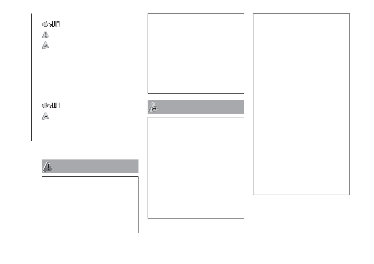
EXHAUST SYSTEM
178) 179)
98)
Adequate maintenance of the engine
exhaust system represents the best
protection against leaks of carbon
monoxide into the passenger
compartment.
AUTOMATIC
TRANSMISSION
99)
Use only a gearbox fluid with the same
characteristics as those indicated in the
"Fluids and lubricants" table (see
"Technical specifications" chapter).
WARNING
177) The air intake system (air cleaner,
rubber hoses, etc.) can be a protection in
the case of blowbacks from the engine. DO
NOT REMOVE this system unless you
need to carry out repair or servicing
operations. Before starting the engine,
ensure that the system has not been
removed: failure to observe this precaution
may result in serious injury.
178) Exhaust emissions are very
dangerous, and may be lethal. They
contain carbon monoxide, a colourless,
odourless gas which can cause fainting
and poisoning if inhaled.
179) The exhaust system may reach high
temperatures and may cause a fire if the
vehicle is parked on flammable material.
Dry grass or leaves can also catch fire if
they come into contact with the exhaust
system. Do not park or use the vehicle in a
place in which the exhaust system might
come into contact with flammable material.
IMPORTANT
92) It is recommended to have the vehicle
serviced by a Fiat Dealership. When
carrying out normal periodic operations and
small servicing interventions personally on
the vehicle, it is recommended to use
suitable equipment, genuine spare parts
and the necessary fluids. Do not carry out
any interventions if you don't have the
necessary experience.
93) Incorrect servicing of the vehicle or
failure to carry out operations or repairs
(when necessary) may lead to more
expensive repairs, damage to other
components or have a negative impact on
the vehicle performance. Have any
malfunction inspected immediately by a Fiat
Dealership.
94) The vehicle is equipped with fluids
which are optimised or protecting its
performance and life and extending service
intervals. Do not use chemicals for washing
these components since they may damage
the engine, the gearbox or the climate
control system. This damage is not covered
by the vehicle’s warranty. If any component
needs to be washed due to malfunctioning,
use only the specific liquid for that
procedure.
95) An excessive or insufficient amount of
oil inside the base is extremely damaging to
the engine. Make sure it is always at an
adequate level.
96) Always require the use of only
compressor coolants and lubricants
approved and suitable for the specific air
conditioning system fitted on the vehicle.
Some non-approved coolants are
flammable and may explode, with the risk
of injuries. The use of non-approved
coolants or lubricants may adversely affect
system efficiency, leading to expensive
repairs.
97) The air conditioner system contains
coolant under high pressure: to avoid
injuries to people or damage to the system,
any coolant addition or repair that requires
to disconnect the cables must be carried
out by a Fiat Dealership.
200
SERVICING AND MAINTENANCE
98) Vehicles equipped with catalytic
converter must be fuelled only with
unleaded petrol. Leaded petrol would
permanently damage the catalytic
converter and eliminate its ability to reduce
polluting emissions, seriously
compromising the engine performance,
which would be irreparably damaged. If the
engine does not work correctly, especially if
it starts irregularly or if there is a reduction
of its performance, immediately go to a Fiat
Dealership. Prolonged and faulty operation
of the engine may cause overheating of the
converter and, as a consequence, possible
damage to the converter and the vehicle.
99) Using a gearbox fluid different from that
approved may compromise gearshifting
quality and/or cause vibration of the
gearbox itself.
LIFTING THE
VEHICLE
If the vehicle needs to be jacked up, go
to a Fiat Dealership, which is equipped
with shop jacks and jack arms.
The vehicle lifting points are marked on
the side skirts with the
symbols (see
illustration in fig. 173 ).
WHEELS AND TYRES
180) 181) 182) 183) 184) 185)
RIMS AND TYRES
For the type of wheel rims and tyres
fitted on the vehicle see the "Wheels"
paragraph in the "Technical data"
chapter.
SNOW CHAINS
100)
Front Wheel Drive and All Wheel
Drive versions
7-mm snow chains can be used on
215/60 R16 95H and 215/55 R17 94V
tyres.
225/45 R18 91V and 225/45 R18 91Y
tyres cannot be fitted with snow chains.
Important
The use of snow chains should be in
compliance with local regulations of
each country. In certain countries, tyres
marked with code M+S (Mud and
Snow) are considered as winter
equipment; therefore their use is
equivalent to that of the snow chains.
The snow chains may be applied only
to the front wheel tyres.
173
F1B0301C
201
Check the tension of the snow chains
after the first few metres have been
driven.
IMPORTANT Using snow chains with
tyres with non-original dimensions may
damage the vehicle.
IMPORTANT Using different size or type
(M+S, snow, etc.) tyres between front
and rear axle may adversely affect
vehicle driveability, with the risk of losing
control of the vehicle and resulting
accidents.
SUGGESTIONS ABOUT
THE ROTATION OF THE
TYRES
The front and rear tyres are subject to
different loads and stress due to
steering, manoeuvres and braking. For
this reason they are subject to uneven
wear.
To resolve this problem, tyres should be
rotated at the appropriate time. Tyre
rotation means moving the wheels to a
different position, with respect to the
vehicle. The single wheel will therefore
operate on a different axle and, where
possible, on the opposite side of the
vehicle.
Tyre rotation contributes to the
preservation of the grip and traction
performance on wet, muddy or snowy
roads, guaranteeing optimal driveability
of the vehicle.
In the case of irregular wear of the tyres
identify the cause and correct it as soon
as possible, by contacting a Fiat
Dealership.
WARNING
180) The road holding qualities of the car
also depend on the correct inflation
pressure of the tyres.
181) If tyre pressure is too low, it may
overheat and be severely damaged as a
result.
182) If the tyres are "unidirectional", do not
switch tyres from the right-hand side of the
vehicle to the left-hand side, and vice
versa. This type of tyres can only be
switched from the front axle to the rear axle
and vice versa, keeping them on the same
side of the vehicle.
183) Never submit alloy rims to repainting
treatments requiring the use of
temperatures exceeding 150°C. The
mechanical properties of the wheels could
be impaired.
184) The wheel rotation methods shown in
the text must NOT be used with one-way
tyres! This type of tyres can only be
switched from the front axle to the rear axle
and vice versa, keeping them on the same
side of the vehicle.
185) Travelling with partially or completely
deflated tyres can cause safety problems
and damage the concerned tyre beyond
repair.
IMPORTANT
100) Keep your speed down when snow
chains are fitted; do not exceed 50 km/h.
Avoid potholes, do not drive over steps or
sidewalks and do not drive long distances
over roads without snow, to avoid
damaging both your vehicle and the road
surface.
202
SERVICING AND MAINTENANCE
BODYWORK
PRESERVING THE
BODYWORK
Paintwork
101)
6)
Touch up abrasions and scratches
immediately to prevent the formation of
rust.
Maintenance of paintwork consists of
washing the vehicle: the frequency
depends on the conditions and
environment in which the vehicle is
used. For example, it is advisable to
wash the vehicle more often in areas
with high levels of atmospheric pollution
or salted roads.
Some parts of the vehicle may be
covered with a matt paint which, in
order to be maintained intact, requires
special care: see the instructions in the
warning at the end of this paragraph
102).
To correctly wash the vehicle, follow
these instructions:
if the vehicle is washed remove the
aerial from the roof;
if high pressure jets or cleaners are
used to wash the vehicle, keep a
distance of at least 40 cm from the
bodywork to avoid damage or
alteration. Build up of water could
cause damage to the vehicle in the long
term;
wash the bodywork using a low
pressure jet of water if possible;
wipe a sponge with a slightly soapy
solution over the bodywork, frequently
rinsing the sponge;
rinse well with water and dry with a
jet of air or a chamois leather.
Dry the less visible parts (e.g. door
frames, bonnet, headlight frames, etc.)
with special care, as water may
stagnate more easily in these areas. Do
not wash the vehicle after it has been
left in the sun or with the bonnet hot:
this may alter the shine of the
paintwork.
Exterior plastic parts must be cleaned
in the same way as the rest of the
vehicle.
IMPORTANT
Avoid parking under trees; the resin
dropped by trees makes the paintwork
go opaque and increases the possibility
of corrosion.
Bird droppings must be washed off
immediately and thoroughly as the acid
they contain is particularly aggressive.
Windows
Use specific detergents and clean
cloths to prevent scratching or altering
the transparency.
IMPORTANT Wipe the rear window
inside gently with a cloth following the
direction of the filaments to avoid
damaging the heating device.
Headlights
Use a soft cloth soaked in water and
detergent for washing cars.
IMPORTANT Never use aromatic
substances (e.g. petrol) or ketones (e.g.
acetone) for cleaning the plastic lenses
of the headlights.
IMPORTANT When cleaning with a
pressure washer, keep the water jet at
least 20 cm away from the headlights.
203
Engine compartment
At the end of every winter, wash the
engine compartment thoroughly, taking
care not to aim the jet of water directly
at the electronic control units or at the
windscreen/rear window wiper motors.
Have this operation performed at a
specialised workshop.
IMPORTANT The washing should take
place with the engine cold and the
ignition device in the STOP position.
After the washing operation, make sure
that the various protections (e.g. rubber
caps and guards) have not been
removed or damaged.
IMPORTANT
101) In order to preserve the aesthetic
appearance of the paint abrasive products
and/or polishes should not be used for
cleaning the vehicle.
102) Avoid washing with rollers and/or
brushes in washing stations. Wash the
vehicle only by hand using neutral pH
detergents; dry it with a wet chamois
leather. Abrasive products and/or polishes
should not be used for cleaning the car.
Bird droppings must be washed off
immediately and thoroughly as the acid
they contain is particularly aggressive.
Avoid (if at all possible) parking the vehicle
under trees; remove vegetable resins
immediately as, when dried, it may only be
possible to remove them with abrasive
products and/or polishes, which is highly
inadvisable as they could alter the typical
opaqueness of the paint. Do not use pure
windscreen washer fluid for cleaning the
front windscreen and rear window; dilute it
min. 50% with water. Only use pure screen
washer fluid when strictly necessary due to
outside temperature conditions.
IMPORTANT
6) Detergents pollute the environment. Only
wash your vehicle in areas equipped to
collect and treat wastewater from this type
of activity.
INTERIORS
186) 187) 188)
Periodically check the cleanliness of the
interior, beneath the mats, which could
cause oxidation of the sheet metal.
SEATS AND FABRIC
PARTS
Remove dust with a soft brush or a
vacuum cleaner. It is advisable to use a
moist brush on velvet upholstery. Rub
the seats with a sponge moistened with
a solution of water and mild soap.
LEATHER SEATS
(where provided)
Remove the dry dirt with a slightly
damp buckskin or cloth, without
exercising too much pressure.
Remove any liquid or grease stains
using an absorbent dry cloth, without
rubbing. Then clean with a soft cloth or
buckskin cloth dampened with water
and mild soap. If the stain persists, use
specific products and observe the
instructions carefully.
IMPORTANT Never use alcohol. Make
sure that the cleaning products used
contain no alcohol or alcohol
derivatives, even in small quantities.
204
SERVICING AND MAINTENANCE
PLASTIC AND COATED
PARTS
103)
Clean interior plastic parts with a damp
cloth (if possible made from microfibre),
and a solution of water and neutral,
non-abrasive detergent.
To clean oily or persistent stains, use
specific products free from solvents and
designed to maintain the original
appearance and colour of the
components.
Remove any dust using a microfibre
cloth, if necessary moistened with
water. The use of paper tissues is not
recommended as these may leave
residues.
GENUINE LEATHER
PARTS
(where provided)
Use only water and mild soap to clean
these parts. Never use alcohol or
alcohol-based products.
Before using a specific product for
cleaning interiors, make sure that it
does not contain alcohol and/or
alcohol-based substances.
WARNING
186) Never use flammable products, such
as petrol ether or rectified petrol to clean
the inside of the car. The electrostatic
charges which are generated by rubbing
during the cleaning operation may cause a
fire.
187) Do not keep aerosol cans in the car:
they might explode. Aerosol cans must not
be exposed to a temperature exceeding
50°C. When the vehicle is exposed to
sunlight, the internal temperature can
greatly exceed this value.
188) There must be no obstacles on the
floor underneath the pedals; make sure
that mats are always flat and do not
interfere with the pedals.
IMPORTANT
103) Never use alcohol, petrols and
derivatives to clean the dashboard and
instrument panel lens.
205

TECHNICAL SPECIFICATIONS
Everything you may find useful for
understanding how your vehicle is
made and works is contained in this
chapter and illustrated with data, tables
and graphics. For the enthusiasts and
the technician, but also just for those
who want to know every detail of their
vehicle.
IDENTIFICATION DATA.........207
ENGINE ..................208
WHEELS .................211
DIMENSIONS ..............213
WEIGHTS .................215
SUPPLIES ................218
FLUIDS AND LUBRICANTS......222
PERFORMANCE ............225
FUEL CONSUMPTION.........226
CO2 EMISSIONS ............229
PRESCRIPTIONS FOR HANDLING
THE CAR AT THE END OF ITS
LIFE ....................231
206
TECHNICAL SPECIFICATIONS
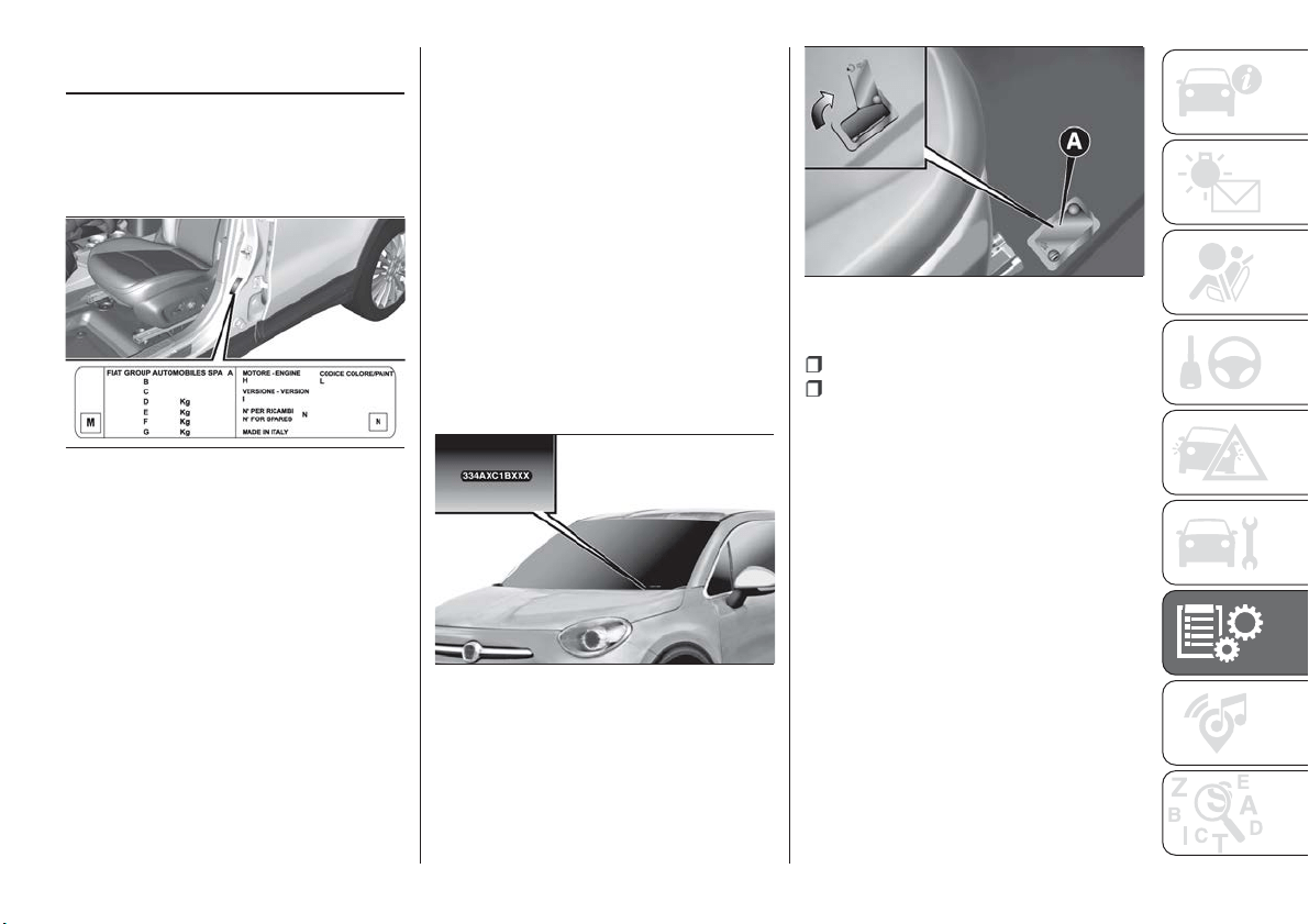
IDENTIFICATION
DATA
VIN PLATE
It is located on the driver's door pillar. It
can be read with the door open and
bears the following data fig. 174:
A
Name of manufacturer
B
Vehicle type-approval number
C
Vehicle identification number
D
Technically allowed max. weight with
full load
E
Technically allowed max. weight for
combined vehicle
F
Technically allowed max. weight on
axle 1
G
Technically allowed max. weight on
axle 2
H
Engine identification
I
Type variant version
L
Paintwork colour code
M
Smoke absorption coefficient (diesel
versions)
N
Further instructions.
CHASSIS MARKING
The Vehicle Identification Number (VIN)
is stamped on the plate shown in
fig. 175, located on the front left corner
of the dashboard cover, which can be
seen from outside the vehicle, through
the windscreen.
This number is also stamped on the
passenger compartment floor, in front
of the front right seat.
To access it, slide flap A fig. 176 in the
direction shown by the arrow.
The marking includes:
type of vehicle;
chassis serial number.
ENGINE MARKING
Engine marking is stamped on the
cylinder block and includes the model
and the chassis serial number.
174
F1B0330C
175
F1B0333C
176
F1B0058C
207
ENGINE
189)
Versions 1.4 T-Jet LPG 120 HP
1.4 Turbo Multi Air
136/140 HP
1.4 Turbo Multi Air
163/170 HP
Engine code 55277701 55263624 55263623
Cycle
Otto Otto Otto
Number and position of
cylinders
4 in line 4 in line 4 in line
Piston bore and stroke (mm) 72 × 84 72 × 84 72 × 84
Total displacement (cm³) 1368 1368 1368
Compression ratio 9.8 ± 0.2 10.0 ± 0.2 10.0 ± 0.2
LPG PETROL
Maximum power (EC) (kW) 88 88
100
(*)
/ 103
120
(**)
/ 125
Maximum power (EEC) (HP) 120 120
136
(*)
/ 140
163
(**)
/ 170
corresponding engine speed
(rpm)
5000 5000 5000 5500
Maximum torque (EEC) (Nm) 215 215 230 250
corresponding engine speed
(rpm)
2500 2500 1750 2500
Spark plugs NGK IKR9J8 NGK IKR9J8 NGK IKR9J8
Fuel
LPG for motor
vehicles
(EN589 Specification)
Unleaded petrol
95 R.O.N.
(EN228 specifications)
Unleaded petrol 95 R.O.N.
(EN228 specifications)
Unleaded petrol 95 R.O.N.
(EN228 specifications)
(*) 1.4 Turbo Multi Air 136 HP version
(**) 1.4 Turbo Multi Air 163 HP version
208
TECHNICAL SPECIFICATIONS
Versions 1.6 E.Torq 2.4 Tigershark(*)
Engine code 55263842
Cycle Otto Otto
Number and position of cylinders 4 in line 4 in line
Piston bore and stroke (mm) 77 × 85.8 88 × 97
Total displacement (cm³) 1598 2360
Compression ratio 11 ± 0.15 10 ± 0.2
Maximum power (EC) (kW) 81 129
Maximum power (EEC) (HP) 110 175
corresponding engine speed (rpm) 5500 6400
Maximum torque (EEC) (Nm) 152 230
corresponding engine speed (rpm) 4500 3900
Spark plugs
NGK - SINGLE IR - ZKR7BI - 10 JAPAN
C128
CHAMPION - SP148183AB
Fuel
Unleaded petrol 95 R.O.N.
(EN228 specifications)
Unleaded petrol 95 R.O.N.
(EN228 specifications)
(*) Version for specific markets
209
Versions 1.3 Multijet 1.6 Multijet 2.0 MultiJet (*) 2.0 MultiJet (**)
Engine code 55266963 55260384 55263087 55263088
Cycle Diesel Diesel Diesel Diesel
Number and position of
cylinders
4 in line 4 in line 4 in line 4 in line
Piston bore and stroke
(mm)
69.6 X 82 79.5 × 80.5 83 × 90.4 83 × 90.4
Total displacement (cm³) 1248 1598 1956 1956
Compression ratio 16.8 ± 0.2 16.5 ± 0.4 16.5 ± 0.4 16.5 ± 0.4
Maximum power (EC)
(kW)
70
88 / 84.4
(***) 103 / 100 (***) 103 / 100 (***)
Maximum power (EC)
(HP)
95
120 / 115
(***) 140 / 136 (***) 140 / 136 (***)
corresponding engine
speed (rpm)
3750 3750 3750 4000
Maximum torque (EC)
(Nm)
200 320 350 350
corresponding engine
speed (rpm)
1750 1750 1750 1500
Fuel
Diesel for motor vehicles
(EN 590 Specification)
Diesel for motor vehicles
(EN 590 Specification)
Diesel for motor vehicles
(EN 590 Specification)
Diesel for motor vehicles
(EN 590 Specification)
(*) Versions with mechanical gearbox
(**) Versions with AT9 automatic transmission
(***) Version for specific markets
WARNING
189) Modifications or repairs to the supply system that are not carried out correctly or do not take the system technical specifications into
account can cause malfunctions leading to the risk of fire.
210
TECHNICAL SPECIFICATIONS
WHEELS
RIMS AND TYRES PROVIDED
190) 191)
Alloy or pressed steel rims. Tubeless radial carcass tyres. All approved tyres are listed in the Registration Document.
IMPORTANT If there are any discrepancies between the Owner Handbook and the Registration Document, take the information
from the latter. For safe driving, the car must be fitted with tyres of the same make and type on all wheels.
IMPORTANT Do not use inner tubes with Tubeless tyres.
Wheels Tyres fitted Winter tyres
6 1/2J x 16 H2 ET40 215 / 60 R16 95H 215 / 60 R16 95Q (M+S)
7J
x 17 H2 ET40
215 / 55 R17 94V
(*)
215 / 55 R17 94Q (M+S)
215 / 55 R17 98V (M+S)
7J x 18 H2 ET40
225 / 45 R18 91V
225 / 45 R18 91Q (M+S)
225 / 45 R18 91Y
(*) Mandatory tyre for some specific versions/markets.
On versions with 215/60 R16 and 215/55 R17 tyres, use smaller snow chains with a maximum projection of 7 mm beyond the
tyre profile.
ECO PACK versions (1.3 Multijet 95 HP / 1.6 Multijet 115/120 HP)
Wheels Tyres fitted Winter tyres
7J x 17 H2 ET40 215 / 55 R17 94V Goodyear 215 / 55 R17 94Q (M+S)
Space-saver wheel (where provided)
Rim: 4.0x16/Tyre: T145/90 R16 106M
211
COLD TYRE INFLATION PRESSURE (bar)
When the tyres are warm, the inflation pressure should be +0.3 bar compared with the prescribed value. However, recheck that
the value is correct with the tyre cold.
With snow tyres, add +0.2 bar to the pressure value prescribed for standard tyres.
If it is necessary to raise the vehicle, refer to the "Raising the vehicle" paragraph in the "In an emergency" chapter.
Tyres
Unladen/medium load Full load
Space-saver
wheel
Front Rear Front Rear
215 / 60 R16 95H 2.4 2.4 2.6 2.6
4.2
215
/ 55 R17 94V 2.4 2.4 2.6 2.6
225 / 45 R18 91V 2.4 2.4 2.6 2.6
225 / 45 R18 91Y 2.4 2.4 2.6 2.6
WARNING
190) If winter tyres with a lower speed rating than that indicated in the Registration Document are used, do not exceed the maximum speed
corresponding to the speed rating of the tyres used.
191) DO NOT fit wheel hub caps when using integral hub caps fixed (with springs) to the steel rim and after sale tyres provided with Rim
Protector. Use of unsuitable tyres and wheel caps may cause sudden decrease of tyre pressure.
212
TECHNICAL SPECIFICATIONS
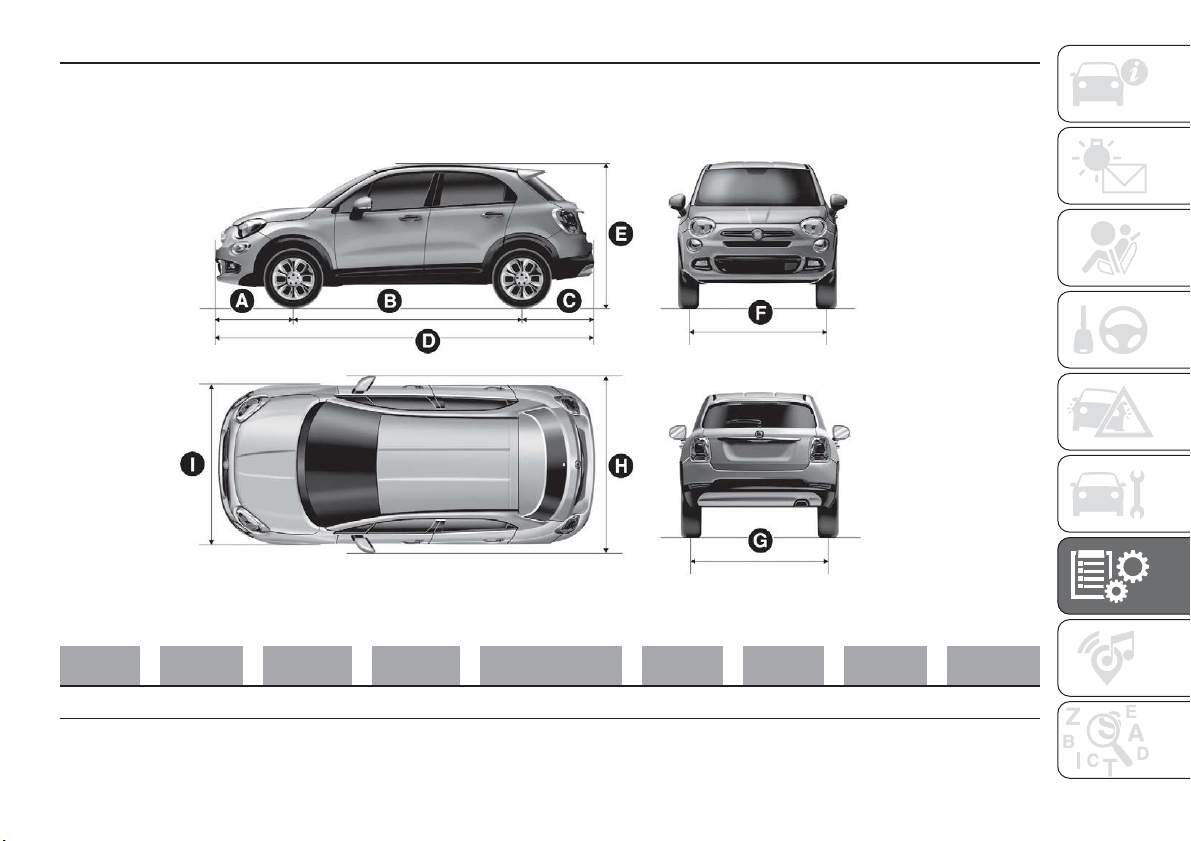
DIMENSIONS
Dimensions are expressed in mm and refer to the vehicle equipped with its standard-supplied tyres. Height is measured with
vehicle unladen. Small variations with respect to the reported values are possible depending on the dimensions of the rims.
AB C D E FGH I
877 2570 801 4248
1600
/ 1608
(*)
1545 1545 2025 1796
(*) With roof rack bars
177
F1B0169C
213
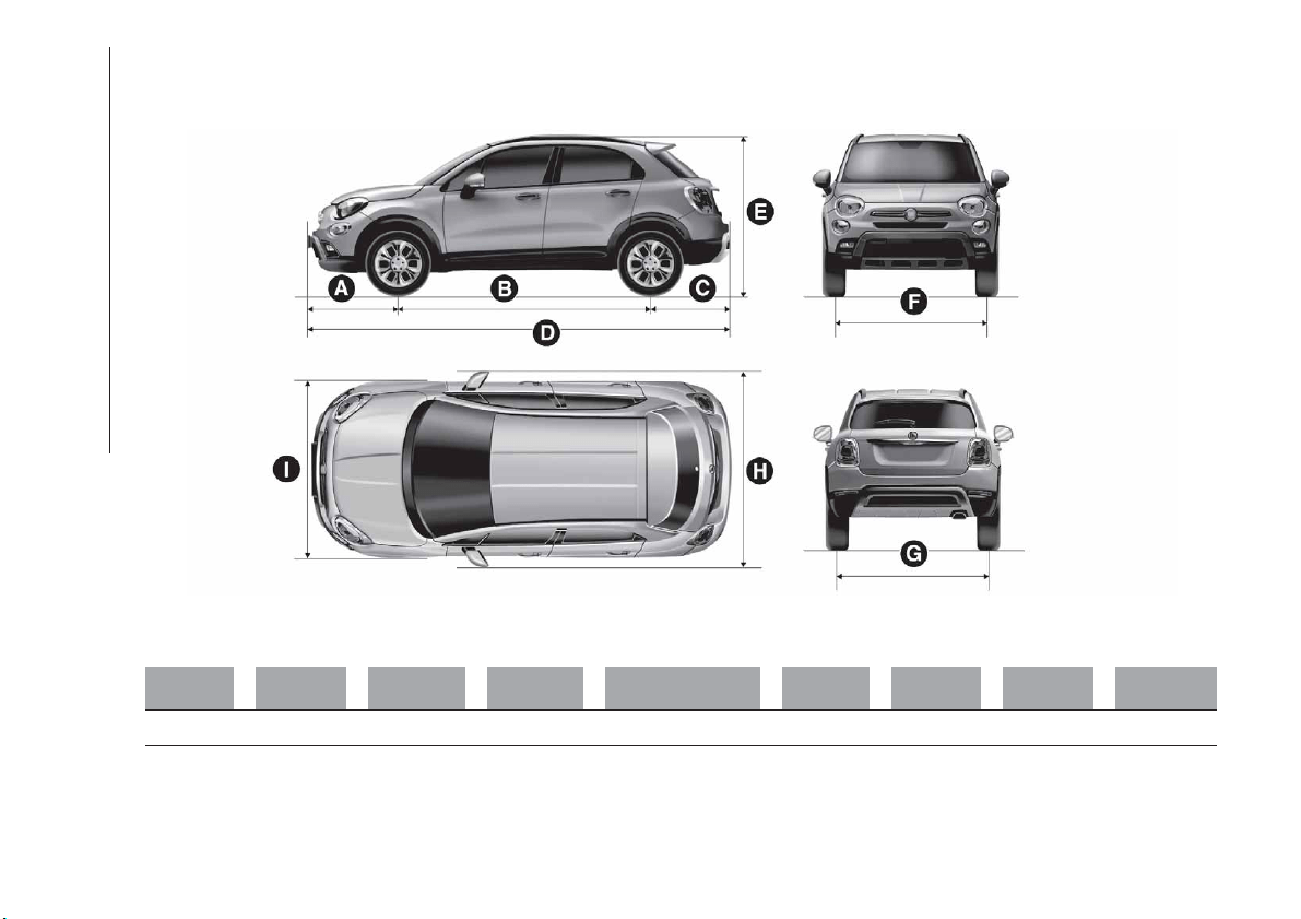
Dimensions are expressed in mm and refer to the vehicle equipped with its standard-supplied tyres. Height is measured with
vehicle unladen. Small variations with respect to the reported values are possible depending on the dimensions of the rims.
AB C D E FGH I
902 2570 801 4273
1608
/ 1620
(*)
1545 1545 2025 1796
(*) 4x4 versions
178
F1B0170C
214
TECHNICAL SPECIFICATIONS
WEIGHTS
Weights (kg) 1.4 T-Jet LPG 120 HP 1.4 Turbo MultiAir(°°) 1.4 Turbo MultiAir(°) 1.6 E.Torq
Unladen weight (with all
fluids,
fuel tank filled to
90% and without
optional equipment)
1320 1320 1430
1275 / 1320
(**)
Payload including the
driver
(*)
555
555 / 540
(**)
670
600 / 555
(**)
Maximum permitted
loads
(***)
– front axle 1050 1050 1150 1050
– rear axle 930 900 1000 900
– total 1875 1875 2100 1875
Towable loads
– braked trailer 900 1200 1200 800
Maximum load on tow
hitch (trailer with brakes)
60
(*****)
60 60 60
Maximum load on
roof
(****)
50 50 50 50
(°°) Manual transmission versions with dual clutch
(°) Versions with AT9 automatic transmission
(**) Version for specific markets
(*) If special equipment is fitted (sunroof, tow hitch, etc.) the unladen car weight increases, thus reducing the specified payload in relation to the maximum
permissible loads.
(***) Loads not to be exceeded. The user is responsible for arranging goods in the luggage compartment and/or on the load platform within the maximum permitted
loads.
(*****) For some versions/markets, trailers cannot be towed so there are no provisions for fitting a tow hook.
(****) With carrier rack
215
Weights (kg) 2.4 Tigershark(*) 1.3 Multijet 1.6 Multijet
Unladen weight (with all fluids,
fuel
tank filled to 90% and
without optional equipment)
1505 1320 1320
Payload including the driver
(**)
595 555
555 / 580
(*****)
Maximum permitted loads(***)
– front axle 1150 1050 1050
– rear axle 1000 900 900
– total 2080 1875
1875 / 1900
(*****)
Towable loads
– braked trailer
1200
(°) / 900 (°°)
1000
1200 / 900
(*****)
Maximum load on tow hitch
(trailer with brakes)
60 60 60
Maximum load on roof
(****)
50 50 50
(*) Version for specific markets
(**) If special equipment is fitted (sunroof, tow hitch, etc.) the unladen car weight increases, thus reducing the specified payload in relation to the maximum
permissible loads.
(*****) Automatic transmission versions with dual clutch
(***) Loads not to be exceeded. The user is responsible for arranging goods in the luggage compartment and/or on the load platform within the maximum permitted
loads.
(°) 4x4 version
(°°) 4x2 version
(****) With carrier rack
216
TECHNICAL SPECIFICATIONS

Weights (kg) 2.0 Multijet (*) 2.0 Multijet (**)
Unladen weight (with all fluids, fuel tank filled
to 90% and without optional equipment)
1430 1495
Payload including the driver
(***)
620 605
Maximum permitted loads
(****)
– front axle 1150 1150
– rear axle 1000 1000
– total 2050 2100
Towable loads
– braked trailer 1200 1200
Maximum load on tow hitch (braked trailer) 60 60
Maximum load on roof
(*****)
50 50
(*) Versions with manual transmission
(**) Versions with AT9 automatic transmission
(***) If special equipment is fitted (sunroof, tow hitch, etc.) the unladen car weight increases, thus reducing the specified payload in relation to the maximum
permissible loads.
(****) Loads not to be exceeded. The user is responsible for arranging goods in the luggage compartment and/or on the load platform within the maximum
permitted loads.
(*****) With carrier rack
217
SUPPLIES
1.4 T-Jet
LPG 120 HP
1.4 Turbo
Multi Air
(*)
1.4 Turbo
Multi Air
(**)
Recommended fuels and original lubricants
Fuel tank (litres) 48 48 48
Unleaded
petrol with RON no lower than 95
(EN228 specifications)
including a reserve of (litres) 5 - 7 5 - 7 5 - 7
Fuel tank (LPG) (litres) 38 – – LPG for motor vehicles (EN589 Specification)
Engine cooling system (litres) 5.2 5.2 5.2
Mixture of distilled water and PARAFLU
UP
50%(***)
Engine sump (litres)
– 3.2 3.2 SELENIA DIGITEK P.E.
2.95 – – SELENIA Multipower GAS
Engine sump and filter (litres)
– 3.6 3.6 SELENIA DIGITEK P.E.
3.25 – – SELENIA Multipower GAS
Gearbox casing/differential (litres) 2.0 1.8 2.1 TUTELA TRANSMISSION GEARFORCE
Hydraulic brake circuit (kg) 0.83 0.83 0.83 TUTELA TOP 4/S
Windscreen and rear window
washer fluid reservoir (litres)
2.5 2.5 2.5
Mixture of water and PETRONAS DURANCE
SC35
(*) Versions with manual transmission
(**) Automatic transmission versions with dual clutch
(***) When the vehicle is used in particularly harsh weather conditions, we recommend using a mixture of 60% PARAFLU
UP
and 40% demineralised water.
218
TECHNICAL SPECIFICATIONS
1.4 Turbo MultiAir(*) 2.4 Tigershark(**) Prescribed fuels and original lubricants
Fuel tank (litres) 48 48
Unleaded
petrol with RON no lower than 95
(EN228 specifications)
including a reserve of (litres) 5 - 7 5 - 7
Engine cooling system (litres) 5.2 6.45
Mixture of distilled water and PARAFLU
UP
50%(***)
Engine sump (litres)
3.2 – SELENIA DIGITEK P.E.
– – SELENIA K POWER 0W-20
Engine sump and filter (litres)
3.6 – SELENIA DIGITEK P.E.
– 5.3 SELENIA K POWER 0W-20
Gearbox casing/differential (litres) 6.0 TUTELA TRANSMISSION AS8
Idler unit (PTU) (litres) – TUTELA TRANSMISSION B-5X
Rear differential (litres) – TUTELA TRANSMISSION COMPAQ DRIVE
Hydraulic brake circuit (kg) 0.83 0.83 TUTELA TOP 4/S
Windscreen and rear window
washer fluid reservoir (litres)
2.5 2.5
Mixture of water and PETRONAS DURANCE
SC35
(*) Versions with AT9 automatic transmission
(**) Version for specific markets
(***) When the vehicle is used in particularly harsh weather conditions, we recommend using a 60-40 mixture of PARAFLU
UP
and demineralised water.
219
1.6 E.Torq 1.3 Multijet Prescribed fuels and original lubricants
Fuel tank (litres) 48 48
Unleaded
petrol with RON no lower than 95 (EN
228 specifications) (1.6 E.Torq versions) / Diesel
for motor vehicles (EN 590 Specification)
(1.3 Multijet versions)
including a reserve of (litres) 5 - 7 5 - 7
Engine cooling system (litres) 5.6 6.1
Mixture of distilled water and PARAFLU
UP
50% (***)
Engine sump (litres) 4.0 3.7
SELENIA DIGITEK P.E. (1.6 E.Torq versions) /
SELENIA WR FORWARD (1.3 Multijet versions)
Engine sump and filter (litres) 4.3 3.9
Transmission/differential casing
(litres)
2.0 2.0 TUTELA TRANSMISSION GEARFORCE
Hydraulic brake circuit (kg) 0.83 0.83 TUTELA TOP 4/S
Windscreen and rear window
washer fluid reservoir (litres)
2.5 2.5
Mixture of water and PETRONAS DURANCE
SC35
(***) When the vehicle is used in particularly harsh weather conditions, we recommend using a 60% mixture of PARAFLU
UP
and 40% demineralised water.
220
TECHNICAL SPECIFICATIONS

1.6 Multijet 2.0 Multijet Prescribed fuels and original lubricants
Fuel tank (litres) 48 48
Diesel
for motor vehicles (EN590 Specification)
including a reserve of (litres) 5 - 7 5 - 7
Engine cooling system (litres) 6.1 6.5
Mixture of distilled water and PARAFLU
UP
50% (*)
Engine sump (litres) 4.4 3.9
SELENIA WR FORWARD
Engine sump and filter (litres) 4.8 4.3
Transmission/differential casing
(litres)
1.8
1.8
(**)
/ 6.0 (***)
TUTELA TRANSMISSION GEARFORCE (versions
with automatic transmission) / TUTELA
TRANSMISSION AS8 (versions with
AT9 automatic transmission)
Idler unit (PTU) (litres) – 0.4 TUTELA TRANSMISSION B-5X
Rear differential (litres) – 0.6 TUTELA TRANSMISSION COMPAQ DRIVE
Hydraulic brake circuit (kg) 0.83 0.83 TUTELA TOP 4/S
Windscreen and rear window
washer fluid reservoir (litres)
2.5 2.5
Mixture of water and PETRONAS DURANCE
SC35
(*) When the vehicle is used in particularly harsh weather conditions, we recommend using a 60% mixture of PARAFLU
UP
and 40% demineralised water.
(**) Versions with manual transmission
(***) Versions with AT9 automatic transmission
221
FLUIDS AND LUBRICANTS
Your vehicle is equipped with an engine oil that has been thoroughly developed and tested in order to meet the requirements of
the Scheduled Servicing Plan. Constant use of the prescribed lubricants guarantees the fuel consumption and emission
specifications. Lubricant quality is crucial for engine operation and duration.
PRODUCT SPECIFICATIONS
Use Features Specification
Original fluids and
lubricants
Replacement interval
Lubricant for petrol
engines
(excluding
2.4 Tigershark)
SAE 0W-30
ACEA C2 / API SN
9.55535-GS1
SELENIA DIGITEK P.E.
Contractual Technical
Reference N° F020.B12
According to Scheduled
Servicing Plan
Lubricant for
2.4 Tigershark
petrol engines
SAE 0W-20
API SN
9.55535-CR1 or MS-6395
SELENIA K POWER
0W-20
Contractual Technical
Reference N° F029.F14
According to Scheduled
Servicing Plan
Lubricant for diesel
engines
SAE 0W-30
ACEA C2
9.55535-DS1 or
MS.90047
SELENIA WR FORWARD
Contractual Technical
Reference N° F842.F13
According to Scheduled
Servicing Plan
Lubricants for
petrol/LPG
engines
SAE 5W-40
ACEA C3/API SM
9.55535-T2
SELENIA Multipower
GAS
Contractual Technical
Reference N° F922.E09
According to Scheduled
Servicing Plan
If lubricants conforming to the specific request are not available, products that meet the indicated specifications can be used to
top up; in this case optimal performance of the engine is not guaranteed.
222
TECHNICAL SPECIFICATIONS
194)
Use Features Specification
Original fluids and
lubricants
Applications
Lubricants and
gr
eases for drive
transmission
Synthetic lubricant.
9.55550-AV5 or
MS.90030-A5
TUTELA TRANSMISSION
AS8
Contractual Technical
Reference N° F139.I11
Lubricant for versions with
AT9 automatic
transmission
Fully synthetic oil with
dedicated additive.
9.55550-SA1 or
MS.90030-H1
TUTELA CS SPEED
Contractual Technical
Reference N° F005.F98
Lubricant for
electro-hydraulic actuator
(dual clutch automatic
transmission versions)
SAE 75W grade synthetic
lubricant.
9.55550-MZ6 or
MS.90030-M1
TUTELA
TRANSMISSION
GEARFORCE
Contractual Technical
Reference N° F002.F10
Manual gearbox and
differential
Molybdenum disulphide
grease, for use at high
temperatures. N.L.G.I.
consistency 1-2.
9.55580-GRAS II
TUTELA ALL STAR
Contractual Technical
Reference N° F702.G07
Wheel side constant
velocity joints
Grease for constant
velocity joints with low
friction coefficient.
N.L.G.I. consistency 0-1.
9.55580-GRAS II
TUTELA STAR 700
Contractual Technical
Reference N° F701.C07
Differential side constant
velocity joints
Diesel fuel additive
Antifreeze additive for
diesel, with protective
action for diesel engines.
PETRONAS DURANCE
DIESEL ART
Contractual Technical
Reference N° F601.L06
To be mixed with diesel
(25 cc per 10 litres)
223
Use Features Specification
Original fluids and
lubricants
Applications
Lubricants and
gr
eases for drive
transmission
SAE 75W-90 API
GL5 grade synthetic
lubricant.
9.55550-DA6
TUTELA
TRANSMISSION B-5X
Contractual Technical
Reference N° F006.A14
Transfer unit (PTU -
4x4 versions)
SAE 75W-90 API
GL5 grade synthetic
lubricant.
9.55550-DA7
TUTELA
TRANSMISSION
COMPAQ DRIVE
Contractual Technical
Reference N° F007.A14
Rear differential
(4x4 versions)
Brake fluid
Synthetic fluid for brake
and clutch systems.
Exceeds specifications:
FMVSS no. 116 DOT 4,
ISO 4925 SAE J1704.
9.55597 or MS.90039
TUTELA TOP 4/S
Contractual Technical
Reference N° F005.F15
Hydraulic brakes and
hydraulic clutch controls
Protective agent for
radiators
Red protective with
antifreeze action, based
on inhibited monoethyl
glycol with organic
formula. Exceeds CUNA
NC 956-16, ASTM D
3306 specifications.
9.55523 or MS.90032
PARAFLU
UP
Contractual Technical
Reference N° F101.M01
Cooling circuits
proportions of use: 50%
water 50% PARAFLU
UP
(**)
Windscreen/rear
window washer fluid
Mixture of spirits and
surfactants. Exceeds
CUNA NC
956-11 specifications.
9.55522 or MS.90043
PETRONAS DURANCE
SC 35
Contractual Technical
Reference N° F001.D16
To be used diluted or
undiluted in screen
washer/wiper systems
(**) When the vehicle is used in particularly harsh weather conditions, we recommend using a mixture of 60% PARAFLU
UP
and 40% demineralised water.
IMPORTANT
104) The use of products with different specifications than those indicated above could cause damage to the engine that is not covered by
the warranty.
224
TECHNICAL SPECIFICATIONS
PERFORMANCE
Top speed reachable after the initial period of usage of the vehicle.
Versions km/h
1.4 T-Jet LPG 120 HP 186
1.4
Turbo Multi Air 140 HP 190
1.4 Turbo Multi Air 140 HP
(*)
190
1.4 Turbo Multi Air 136 HP
(*)
187
1.4 Turbo Multi Air 170 HP 4x4
(**)
200
1.4 Turbo Multi Air 163 HP 4x4
(**) (***)
197
1.6 E.Torq 180
2.4 Tigershark
(***)
190
1.3 MultiJet 95 HP 172
1.6 MultiJet 120 HP 186
1.6 MultiJet 120 HP
(*)
186
1.6 Multijet 115 HP
(***)
183
1.6 Multijet 115 HP
(*)
183
2.0 Multijet 140 HP 4x4 190
2.0 Multijet 140 HP 4x4
(*)
190
2.0 Multijet 136 HP 4x4
(***)
187
2.0 Multijet 136 HP 4x4
(*) (***)
187
(*) Automatic transmission versions with dual clutch
(**) Versions with AT9 automatic transmission
(***) Version for specific markets
225

FUEL CONSUMPTION
The fuel consumption values given in the table below are determined on the basis of the type-approval tests laid down by
specific European Directives. The procedures below are followed for measuring consumption:
urban cycle: cold starting followed by driving that simulates urban use of the vehicle;
extra-urban cycle: frequent accelerating in all gears, simulating extra-urban use of the vehicle: speed varies between 0 and
120 km/h;
combined fuel consumption: calculated with a weighting of approximately 37% of the urban cycle and 63% of the
extra-urban cycle.
IMPORTANT The type of route, traffic conditions, weather conditions, driving style, general condition of the car, trim
level/equipment/accessories, use of the climate control system, car load, presence of roof racks and other situations that
adversely affect the aerodynamics or wind resistance lead to different fuel consumption figures than those measured. The fuel
consumption will get more regular only after having driven the first 3000 km.
226
TECHNICAL SPECIFICATIONS
FUEL CONSUMPTION ACCORDING TO THE CURRENT EUROPEAN DIRECTIVE
(litres/100 km)
Versions Urban Extra-urban Combined
1.4 T-Jet LPG 120 HP
9.2(°)
/ 9.1
(°) (°°°)
12.2(°°)
/ 12.1
(°°) (°°°)
5.3(°)
/ 5.3
(°) (°°°)
7.0(°°)
/ 6.9
(°°) (°°°)
6.7(°)
/ 6.7
(°) (°°°)
8.9(°°)
/ 8.9
(°°) (°°°)
1.4 Turbo Multi Air 136/140 HP 7.8 5.0 6.0
1.4 Turbo Multi Air 136/140 HP
(*)
7.6 4.9 5.9
1.4 Turbo Multi Air 136/140 HP
(**)
7.2 4.9 5.7
1.4 Turbo Multi Air 136/140 HP
(*) (**)
7.0 4.8 5.6
1.4 Turbo Multi Air 163/170 HP 4x4
(***)
8.5 5.7 6.7
1.6 E.Torq 110HP 8.7 5.0 6.4
1.6 E.Torq 110 HP Start&Stop 7.8 5.0 6.0
2.4 Tigershark
(****)
1.3 MultiJet 95 HP 4.7 3.8 4.1
1.3 MultiJet 95 HP
(*****)
4.5 3.7 4.0
1.6 Multijet 115/120 HP 4.7 3.8 4.1
1.6 Multijet 115/120 HP
(**)
4.8 4.0 4.3
1.6 Multijet 115/120 HP
(*)
4.4 3.8 4.0
(°) Running on petrol
(°°°) ECO PACK versions
(°°) Running on LPG
(*) Low environmental impact versions for specific markets (low emissions)
(**) Automatic transmission versions with dual clutch
(***) Versions with AT9 automatic transmission
(****) Version for specific markets
(*****) ECO PACK versions
227
Versions Urban Extra-urban Combined
1.6 Multijet 115/120 HP (*****)
4.4 3.8 4.0
1.6 Multijet 115/120 HP
(*) (**)
4.7 4.0 4.3
1.6 Multijet 115/120 HP
(**) (******)
4.7 4.0 4.2
2.0 Multijet 136/140 HP 4x4 5.8 4.4 4.9
2.0 Multijet 136/140 HP 4x4
(***)
6.5 4.9 5.5
(*****) ECO PACK versions
(*) Low environmental impact versions for specific markets (low emissions)
(**) Automatic transmission versions with dual clutch
(******) Ultra low environmental impact versions for specific markets (low emissions)
(***) Versions with AT9 automatic transmission
228
TECHNICAL SPECIFICATIONS
CO2 EMISSIONS
The CO
2
emission levels given in the following table refer to combined consumption.
Versions
CO EMISSIONS
2
ACCORDING TO THE EUROPEAN DIRECTIVE IN FORCE
(g/km)
1.4 T-Jet LPG 120 HP
157
(°) / 155(°) (°°°)
145(°°) / 143(°°) (°°°)
1.4 Turbo Multi Air 136/140 HP 139
1.4 Turbo Multi Air 136/140 HP
(*)
137
1.4 Turbo Multi Air 136/140 HP
(**)
133
1.4 Turbo Multi Air 136/140 HP
(*) (**)
131
1.4 Turbo Multi Air 163/170 HP 4x4
(***)
157
1.6 E.Torq 110HP 147
1.6 E.Torq 110 HP Start&Stop 139
2.4 Tigershark
(****)
1.3 MultiJet 95 HP 107
1.3 MultiJet 95 HP
(*****)
105
1.6 Multijet 115/120 HP 109
(°) Running on petrol
(°°°) ECO PACK versions
(°°) Running on LPG
(*) Low environmental impact versions for specific markets (low emissions)
(**) Automatic transmission versions with dual clutch
(***) Versions with AT9 automatic transmission
(****) Version for specific markets
(*****) ECO PACK versions
229
Versions
CO EMISSIONS
2
ACCORDING TO THE EUROPEAN DIRECTIVE IN FORCE
(g/km)
1.6 Multijet 115/120 HP
(*)
107
1.6 Multijet 115/120 HP
(*****)
106
1.6 Multijet 115/120 HP
(*) (**)
111
1.6 Multijet 115/120 HP
(**) (******)
110
2.0 Multijet 136/140 HP 4x4 130
2.0 Multijet 136/140 HP 4x4
(***)
144
(*) Low environmental impact versions for specific markets (low emissions)
(*****) ECO PACK versions
(**) Automatic transmission versions with dual clutch
(******) Ultra low environmental impact versions for specific markets (low emissions)
(***) Versions with AT9 automatic transmission
230
TECHNICAL SPECIFICATIONS
PRESCRIPTIONS FOR HANDLING THE CAR AT THE END OF ITS
LIFE
(where provided)
FCA has been committed for many years to safeguarding the environment through the constant improvement of its production
processes and manufacturing products that are increasingly "eco-compatible". To grant customers the best possible service in
terms of respecting environmental laws and in response to European Directive 2000/53/EC governing vehicles at the end of
their life, FCA is offering its customers the chance to hand over their vehicle at the end of its life without incurring any additional
costs. The European Directive sets out that when the vehicle is handed over, the last keeper or owner should not incur any
expenses as a result of it having a zero or negative market value.
To hand your vehicle over at the end of its life without extra cost, contact one of our dealerships if you are purchasing another
vehicle or an FCA-authorised collection and scrapping centre. These centres have been carefully chosen to offer high quality
service for the collection, treatment and recycling of vehicles at their end of life, respecting the surrounding environment.
You can find further information on these collection and scrapping centres either from an FCA dealership or by calling the
number in the Warranty Booklet or by consulting the websites of the various FCA brands.
231

MULTIMEDIA
This chapter describes the main
functions of the Uconnect™ Radio or
Uconnect™ 7” HD LIVE or
Uconnect™ 7” HD Nav LIVE remote
info systems which may be installed on
the car.
TIPS, CONTROLS AND GENERAL
INFORMATION..............233
Uconnect™ Radio ...........235
Uconnect™ 7” HD LIVE /
Uconnect™ 7” HD Nav LIVE .....245
MOPAR CONNECT ...........261
OFFICIAL TYPE APPROVALS . . . .262
232
MULTIMEDIA
TIPS, CONTROLS
AND GENERAL
INFORMATION
ROAD SAFETY
Learn how to use the various system
functions before setting off.
Read the instructions for the system
carefully before setting off.
192) 193)
RECEPTION CONDITIONS
Reception conditions change
constantly while driving. Reception may
be interfered with by the presence of
mountains, buildings or bridges,
especially when you are far away from
the broadcaster.
IMPORTANT The volume may be
increased when receiving traffic alerts
and news.
CARE AND
MAINTENANCE
Observe the following precautions to
ensure the system is fully operational:
the display lens should not come into
contact with pointed or rigid objects
which could damage its surface; use a
soft, dry anti-static cloth to clean and
do not press.
never use alcohol, petrols and
derivatives to clean the display lens.
prevent any liquid from entering the
system: this could damage it beyond
repair.
105) 106)
MULTIMEDIA DEVICES
IMPORTANT Some multimedia players
may not be compatible with the
Uconnect™.
Only use devices (e.g. USB flash drives)
from safe sources on the car. Devices
from unknown sources could contain
software infected by viruses which, if
installed on the car, could increase the
vulnerability of the car's electric/
electronic systems to hacking.
ANTITHEFT PROTECTION
The system is equipped with an
anti-theft protection system based on
the exchange of information with the
electronic control unit (Body Computer)
on the vehicle.
This guarantees maximum safety and
prevents the secret code from being
entered after the power supply has
been disconnected.
If the check has a positive outcome, the
system will start to operate, whereas if
the comparison codes are not the same
or if the electronic control unit (Body
Computer) is replaced, the system will
ask the user to enter the secret code
according to the procedure described
in the paragraph below.
Entering the secret code
When the system is switched on, if the
code is requested, the display will show
"Please enter Anti-Theft Code" followed
by the screen showing a keypad to
enter the secret code.
The secret code is made up of four
digits, from 0 to 9: to insert the code,
turn the "BROWSE ENTER" right knob
and press to confirm.
After inserting the fourth digit, move the
cursor to "OK" and press the
"BROWSE ENTER" right knob: the
system will start to operate.
233
If an incorrect code is entered, the
system displays "Incorrect Code" to
notify the user of the need to enter the
correct code.
After the 3 available attempts to enter
the code, the system displays
"Incorrect Code. Radio locked. Wait for
30 minutes". After the text has
disappeared it is possible to start the
code entering procedure again.
Vehicle radio passport
This document certifies ownership of
the system. The vehicle radio passport
shows the system model, serial number
and secret code.
In case of loss of the car radio
passport, contact the Fiat Dealership,
taking an ID document and the car
ownership documents.
IMPORTANT Keep the vehicle radio
passport in a safe place so that you
can give the information to the relevant
authorities if the system is stolen.
IMPORTANT
Look at the screen only when it is
necessary and safe. If you need to look
at the screen for a long time, pull over
to a safe place so as not to be
distracted while driving.
Immediately stop using the system in
the event of a fault. Otherwise the
system might be damaged. Contact a
Fiat Dealership as soon as possible to
have the system repaired.
WARNING
192) Follow the safety rules here below:
otherwise serious injuries may occur to the
occupants or the system may be
damaged.
193) If the volume is too loud this can be
dangerous. Adjust the volume so that you
can still hear background noises (e.g.
horns, ambulances, police vehicles, etc.).
IMPORTANT
105) Only clean the front panel and the
display lens with a soft, clean, dry,
anti-static cloth. Cleaning and polishing
products may damage the surface. Never
use alcohol, petrols and derivatives.
106) Do not use the display as a base for
supports with suction pads or adhesives for
external navigators or smartphones or
similar devices.
234
MULTIMEDIA
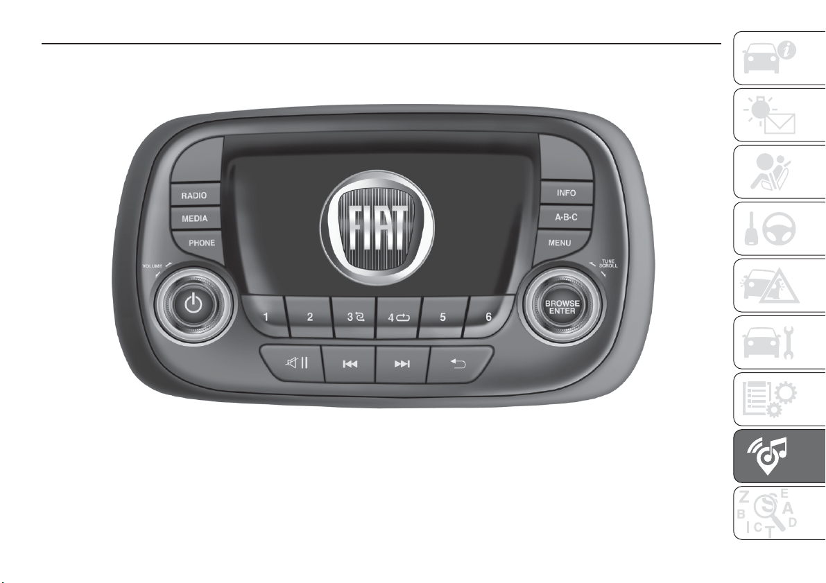
Uconnect™ Radio
CONTROLS ON FRONT PANEL
179
F1B0623C
235
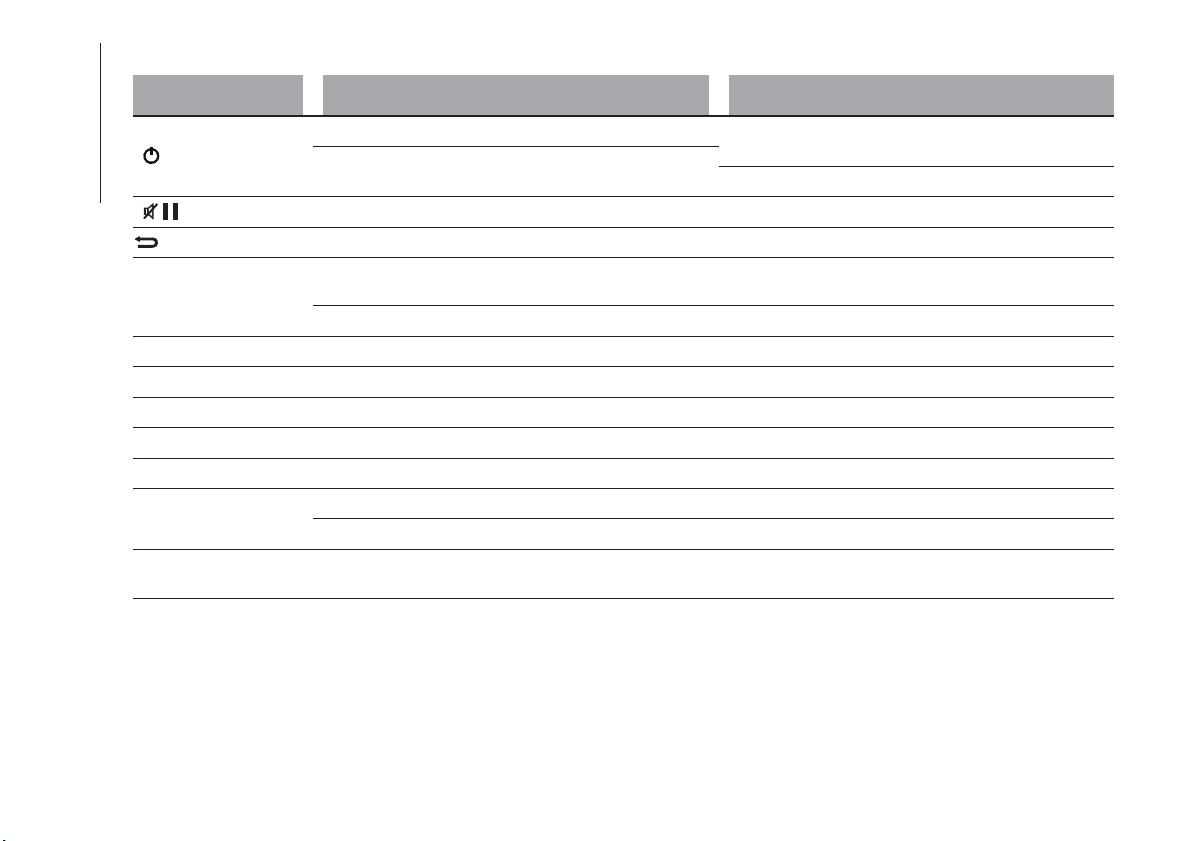
FRONT CONTROL PANEL SUMMARY TABLE
Button Functions Mode
Power on/off
Short button press
Volume adjustment
Left/right rotation of knob
Volume activation/deactivation (Mute/Pause) Short button press
Exit the selection/return to previous screen Short button press
BROWSE ENTER
Scrolling the list or tuning to a radio station or select
previous/next track
Left/right rotation of knob
Confirmation of the option displayed Short button press
INFO Display mode selection (Radio, Media Player) Short button press
PHONE Access to the Phone mode Short button press
MENU Access to the Settings menu Short button press
MEDIA Source selection: USB or AUX Short button press
RADIO Access to the Radio mode Short button press
1-2-3-4-5-6
Store current radio station Long button press
Stored radio station recall Short button press
A-B-C
Selection of the group of radio presets or selection of
the desired letter in each list
Short button press
236
MULTIMEDIA
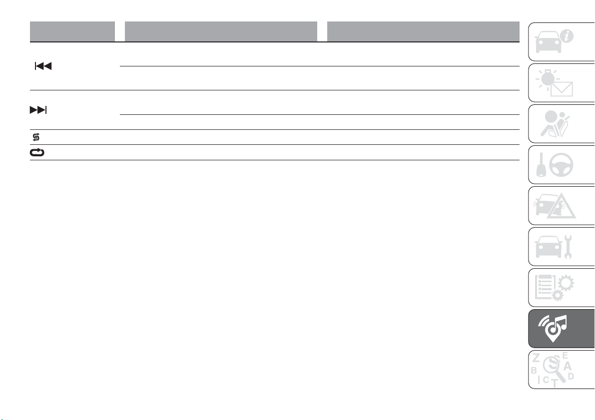
Button Functions Mode
Search for previous radio station or selection of USB
previous track
Short button press
Scan of lower frequencies until beginning of previous
track
Long button press
Search for next radio station or selection of USB next
track
Short button press
Scan of higher frequencies beginning of next track Long button press
Shuffle of USB tracks Short button press
USB track repeat Short button press
237
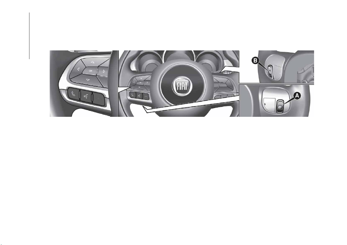
STEERING WHEEL CONTROLS
The controls for the main system functions are present on the steering wheel to make control easier.
The activation of the function selected is controlled, in some cases, by how long the button is pressed (short or long press) as
described in the table below.
180
F1B0213C
238
MULTIMEDIA
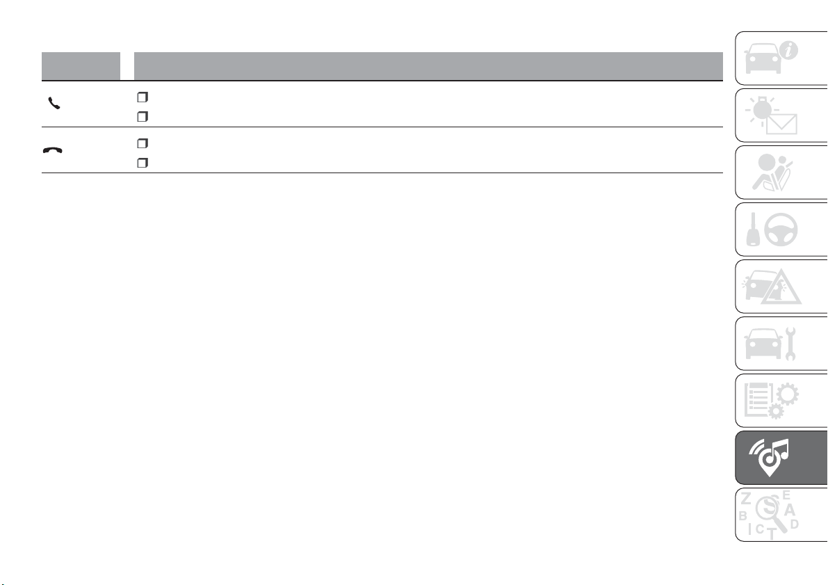
CONTROLS ON STEERING WHEEL SUMMARY TABLE
Button Interaction
Acceptance of incoming call
Acceptance of the second incoming call and putting the active call on hold
Rejection of incoming call
Ending of call in progress
239

CONTROLS BEHIND THE STEERING WHEEL
Buttons Interaction
Button A (left side, behind the steering wheel)
Upper
button
Brief button press: search for next radio station or selection of USB next track
Long button press: scan of higher frequencies until released/fast forward of USB
track
Central button
With each press it scrolls through sources AM, FM, USB, AUX. Only the available
sources will be selected.
Lower button
Brief button press: search for next radio station or select USB previous track
Long button press: scan of lower frequencies until released/fast forward of USB
track.
Button B (right side, behind the steering wheel)
Upper button
Increasing volume
Brief button press: single volume increase
Long button press: fast volume increase
Central button Activation/deactivation of Mute function
Lower button
Decreasing volume
Brief button press: single volume decrease
Long button press: fast volume decrease
240
MULTIMEDIA
SWITCHING THE SYSTEM
ON/OFF
The system is switched on/off by
pressing the
button/knob.
Turn the button/knob clockwise to
increase the radio volume or
anticlockwise to decrease it.
RADIO (TUNER) MODE
The system features the following
tuners: AM, FM.
RADIO MODE SELECTION
Press the RADIO button on the front
panel to activate radio mode.
FREQUENCY BAND
SELECTION
The different tuning modes can be
selected by pressing the RADIO button
on the front panel.
DISPLAYED
INFORMATION
After the desired radio station is
selected on the display, the following
information is shown (INFO mode
activated):
In the upper part: the preset station, the
time and the other active radio settings
are highlighted.
In the central part: the name of the
current station, the frequency and the
radio text information (if any) are
highlighted.
FM station list
Press the BROWSE ENTER
button/knob to display the complete list
of the FM stations that can be received.
SETTING THE PRESETS
The preset stations are available in all
system modes and are selected by
touching one of the presetting buttons
1-2-3-4-5-6 on the front panel.
If you are tuned to a radio station that
you wish to store, hold down the button
on the display which corresponds to
the desired preset until an acoustic
confirmation signal is emitted.
RADIO STATION
SELECTION
To search for the desired radio station
press the
or button or use
the wheel of the steering wheel controls
, or turn the "BROWSE ENTER"
knob.
PREVIOUS/NEXT RADIO
STATION SEARCH
Press briefly the or button
or use the wheel of the steering wheel
controls
: when the button is
released the previous or next radio
station is displayed.
PREVIOUS/NEXT RADIO
STATION FAST SEARCH
Hold down the or button to
start the fast search: when the button is
released, the first tunable radio is
played.
MEDIA MODE
Press the MEDIA button to select the
desired audio source among those
available: AUX or USB.
To select and playback music tracks on
the mobile phone CD card (where the
phone allows) press the BROWSE
ENTER button/knob, select Folders
then Card.
IMPORTANT Some multimedia player
devices may not be compatible with the
Uconnect™ system.
TRACK CHANGE
(previous/next)
Briefly press the button or turn
the BROWSE ENTER button/knob
clockwise to play the next track.
Briefly press the
button or turn
the BROWSE ENTER button/knob
anticlockwise to return to the beginning
of the selected track or to the beginning
of the previous track (if this has been
played for less than 3 seconds).
241
TRACK FAST FORWARD/
REWIND
Hold down the button to fast
forward the selected track.
Hold down the
button to fast
rewind the track.
TRACK SELECTION
(Browse)
Use this function to scroll through and
select the tracks on the active device.
The choices available depend on the
device connected.
For example, on a USB device, you can
also use the BROWSE ENTER
button/knob to scroll through the list of
artists, genres and albums available on
the device, depending on the
information available in the tracks.
Within each alphabetical list, the A-B-C
button on the front panel allows the
user to skip to the desired letter in the
list.
NOTE This button might be disabled for
some
Apple
®
devices.
NOTE The BROWSE ENTER button
does not allow any operation on an
AUX device.
Press the BROWSE ENTER button to
activate this function on the source
being played.
Turn the BROWSE ENTER button/knob
to select the desired category and then
press the button/knob to confirm the
selection.
Press the
button to cancel the
function.
TRACK INFORMATION
DISPLAY
Press the INFO button to select the
information displayed while playing
(Artist, Album, Genre, Name, Folder, File
name).
Press the
button to exit the
screen.
SHUFFLE
Press the button to play the tracks
on USB in a random order.
Press the button again to deactivate the
function.
TRACK REPETITION
To listen to the track again, press the
button.
Press again to deactivate the function.
AUX SUPPORT
To activate AUX mode, insert an
appropriate device in the AUX socket
on the vehicle.
Adjust the volume using the
button/knob on the front panel or
using the volume adjustment control on
the connected device.
For the "Audio source selection"
function, see the "Media mode"
chapter.
IMPORTANT
The functions of the device connected
with the AUX socket are directly
managed by the device itself: it is not
possible to change track/folder/playlist
or control playing start/end/pause with
the controls on the front panel or on the
steering wheel.
Do not leave the cable of your portable
player connected to the AUX socket
after disconnection, to avoid possible
hiss from the speakers.
242
MULTIMEDIA
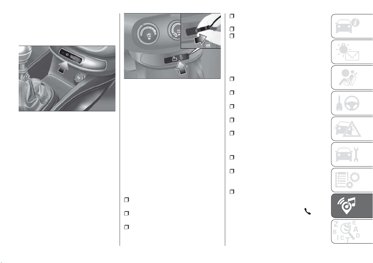
USB SOURCE
To activate the USB mode, insert the
corresponding device into the USB port
on the central tunnel fig. 181.
IMPORTANT After using a USB
recharging socket, we recommend
disconnecting the device (smartphone),
always removing the cable from the
vehicle socket first, never from the
device fig. 182. Cables left flying or
connected incorrectly could
compromise correct recharging and/or
the USB socket condition.
PHONE MODE
Phone mode activation
Press the PHONE button on the front
panel to activate the Phone mode.
If no mobile phone is connected, the
respective display warning screen
appears:
Pairing of a
Bluetooth
®
mobile
phone
The system connects automatically to
the paired mobile phone with the
highest priority.
To choose a specific
Bluetooth
®
mobile phone, proceed as follows:
press the MENUbutton on the front
panel;
select "Phone menu/Bluetooth" on
the display;
select the "Bluetooth/Phones" list
using the corresponding button;
select the specific device
(
Bluetooth
®
mobile phone);
select "Connect";
the device connected is highlighted
in the list.
Unpairing of a
Bluetooth
®
mobile
phone
To disconnect a specific
Bluetooth
®
mobile phone, proceed as follows:
press the MENUbutton on the front
panel;
select "Phone menu/Bluetooth" on
the display;
select the "Bluetooth/Phones" list
using the corresponding button;
select the specific device (mobile
phone or
Bluetooth
®
device);
select "Disconnect".
Making a phone call
A call can be made by:
selecting "Contacts" (Phonebook
......);
select the “Recent calls list”: the
received, made and missed calls are
viewed;
press PHONE on the front panel,
then select “Keypad” to enter the
numbers using the “BROWSE/ENTER”
right knob and finally press the
icon
to make the call. Alternatively, you can
use the keypad of your phone (not while
driving).
181
F1B0006C
182
F1B0395C
243

Ending a call
Press the "End" button or the
button on the steering wheel
controls (where present) to end a call in
progress.
SETTINGS
Press the MENU button on the front
panel to display the "Settings" menu.
NOTE The menu items displayed can
vary according to the versions.
The menu includes the following items:
System Settings: Language, Reset
Default Value, System Power Off,
Power on Volume Limit, Auto-On Radio.
Radio Settings: Browse FM Station
List, Traffic Announcements, Regional,
Alternative Frequency.
Radio off delay: allows the system
to be kept on for a preset time after the
ignition device has been turned to
STOP.
Audio settings: access the audio
settings menu.
Telephone: access to the telphone
settings menu.
AUDIO SETTINGS
This option accesses the audio settings
menu.
The menu includes the following items:
TREBLE: adjustment of high tones;
MID: adjustment of mid tones;
BASS: adjustment of bass tones;
FADER: balancing of front/rear
speakers;
BALANCE: balancing of left/right
speakers;
SVC: speed adjustment according to
vehicle speed;
LOUDNESS: audio improvement at
low volume;
AUX OFFSET: alignment of the
portable device volume with that of the
other sources.
244
MULTIMEDIA
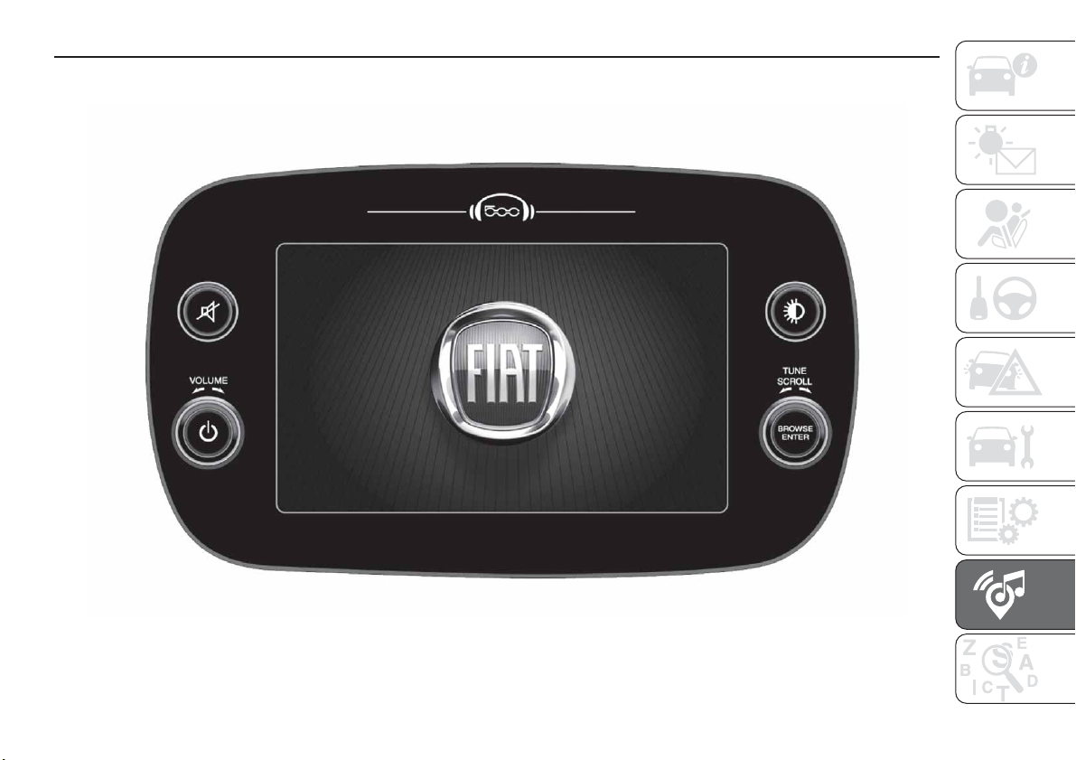
Uconnect™ 7” HD LIVE / Uconnect™ 7” HD Nav LIVE
CONTROLS ON FRONT PANEL
183
F1B0520C
245
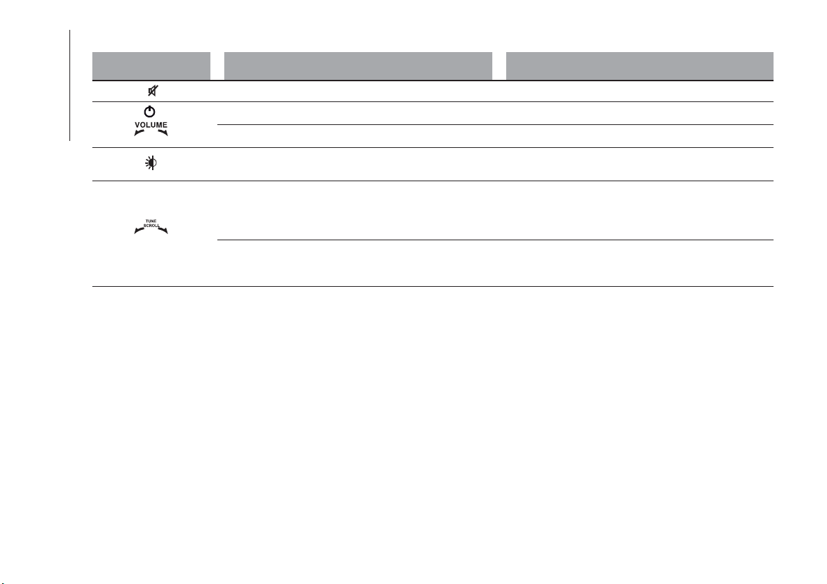
FRONT CONTROL PANEL SUMMARY TABLE
Button Functions Mode
Volume activation/deactivation (Mute/Pause) Short button press
Power on/off Short button press
Volume adjustment Left/right rotation of knob
Display on/off Short button press
BROWSE ENTER
Scrolling the list or tuning to a radio station.
Station change (RADIO mode)
Scroll contents of sources (Media mode)
Media source track change
Left/right rotation of knob
Confirmation of the option displayed. Open browsing
list (Radio or Media mode)
Display list of stations (Radio mode)
Short button press
246
MULTIMEDIA
SUMMARY TABLE OF DISPLAY BUTTONS
Button Functions Mode
Radio Access
to the Radio mode Press button
Media
Source selection: USB, AUX (where provided),
Bluetooth
®
Press button
Phone Access to the Phone mode Press button
Uconnect™
Access to the system functions (Audio, Media, Phone,
Radio, Uconnect
™ LIVE services, etc.)
Press button
Nav
(*)
Access to the Navigation menu Press button
Settings Access the settings menu Press button
Trip Access to the Trip function Press button
(*) Uconnect™ HD Nav LIVE versions only
247

STEERING WHEEL CONTROLS
The controls for the main system functions are present on the steering wheel to make control easier.
The activation of the function selected is controlled, in some cases, by how long the button is pressed (short or long press) as
described in the table below.
184
F1B0213C
248
MULTIMEDIA
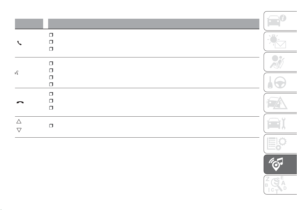
CONTROLS ON STEERING WHEEL SUMMARY TABLE
Button Interaction
Acceptance of incoming call
Acceptance of the second incoming call and putting the active call on hold
Display on the instrument panel of the list of the last 10 calls and favourite phone numbers (only with call browsing
active)
Activation of voice recognition
Interruption of the voice message in order to give a new voice command
Interruption of voice recognition
Long press: activation of Siri, Apple CarPlay and Android Auto functions
Rejection of incoming call
Ending of call in progress
Exit the display of the last calls on the instrument panel display (only with call browsing active) (for versions/markets,
where provided)
Short press (Phone mode): selection, on the instrument panel display, of the last calls/text messages (only with call
browsing active)
249
CONTROLS BEHIND THE STEERING WHEEL
Buttons Interaction
Button A (left side, behind the steering wheel)
Upper
button
Brief button press: search for next radio station or selection of USB next track
Long button press: scan of higher frequencies until released/fast forward of USB
track
Central button
With each press it scrolls through sources AM, FM, USB, AUX (where provided). Only
the available sources will be selected.
Lower button
Brief button press: search for next radio station or select USB previous track
Long button press: scan of lower frequencies until released/fast forward of track
on USB and SD (where provided).
Button B (right side, behind the steering wheel)
Upper button
Increasing volume
Brief button press: single volume increase.
Long button press: fast volume increase.
Central button Activation/deactivation of Mute function
Lower button
Decreasing volume
Brief button press: single volume decrease.
Long button press: fast volume decrease.
250
MULTIMEDIA
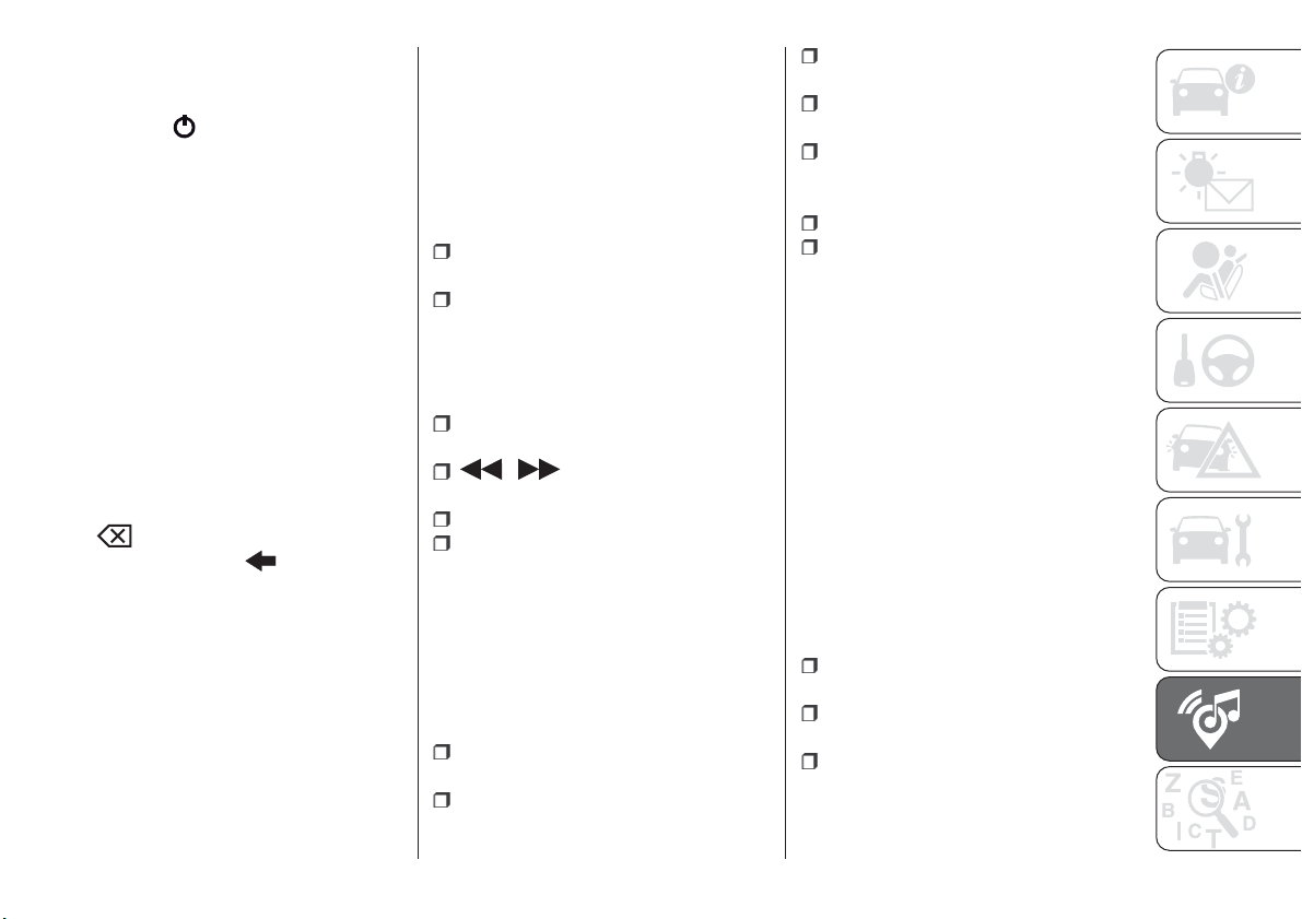
SWITCHING THE SYSTEM
ON/OFF
The system is switched on/off by
pressing the
button/knob.
Turn the button/knob clockwise to
increase the radio volume or
anticlockwise to decrease it. The
electronic volume adjustment control
rotates continuously (360°) in both
directions, without stop positions.
"TOUCH SCREEN"
FUNCTION
The system uses the "touch screen”
function; to interact with the different
functions, press the "graphic buttons"
displayed.
Confirming a selection: press the
"OK" button.
Return to the previous screen: press
the
(Delete) button or, depending
on the active screen,
/Done.
RADIO MODE
After the desired radio station is
selected, the following information is
shown on the display:
At the top: the list of radio stations
stored (preset) is displayed; the station
currently playing is highlighted.
At the centre: the name of station
being listened too is displayed.
On the left side: the "AM", "FM",
"DAB” (for versions/markets, where
provided) buttons to select the desired
frequency band are displayed (the
button corresponding to the selected
band is highlighted);
On the right: display of the following
buttons:
“Info”: additional information on the
source being listened to;
“Map": navigation map view (versions
with Uconnect™ 7" HD Nav LIVE
only).
At the bottom: display of the following
buttons:
“Browse”: list of the radio stations
available;
/ selecting previous/next
radio station;
“Tune” : manual radio station tuning;
“Audio”: access to the “Audio
Settings” screen.
Audio menu
To access the "Audio" menu press the
Audio" button located at the bottom of
the display.
The following adjustments can be
carried out using the “Audio” menu:
“Balance & Fader" (left/right and
front/rear audio balance adjustment)
"Equaliser" (for versions/markets,
where provided)
“Speed Adj Volume” (speed-
dependent automatic volume control)
"Loudness" (for versions/markets,
where provided)
“AUX Volume compensation” (only
active if an AUX device is inserted)
(where provided)
“AutoPlay”
“Auto-On Radio”
MEDIA MODE
Press the "Media" button to select the
desired audio source among those
available: USB,
Bluetooth
®
and AUX
(where provided).
IMPORTANT Applications used on
portable devices may be not
compatible with the Uconnect™
system.
After Media mode is selected, the
following information is shown on the
display.
At the top: information on the track
being played and the following graphic
buttons:
“Repeat”: to repeat the track being
played
“Shuffle”: to play the tracks in
random order
Track progress and duration
In the middle: information on the track
being played.
251
On the left: display of the following
buttons:
Selected device or audio source
“Select Source”: select the required
audio source
On the right: display of the following
buttons:
"Info": additional information about
the track playing
“Tracks”: list of available tracks
“Map": navigation map view (versions
with Uconnect™ 7" HD Nav LIVE only)
At the bottom: information on the
track being played and the following
graphic buttons:
“Bluetooth” (for Bluetooth
®
audio
source): displays the list of devices
“Browse” (for USB source): opens
browsing
/ : previous/next track
selection;
: pause track being played
“Audio”: access to the “Audio
Settings” screen
Track selection
The “Tracks” function allows you to
open a window with the list of tracks
being played.
The choices available depend on the
device connected. For example, on a
USB device you can also scroll through
the list of artists, genres and albums
available on the device depending on
the information present on the tracks
using the TUNE SCROLL button/knob
or by means of the
and
buttons.
Within each list, the “ABC” button
allows the user to skip to the desired
letter in the list.
NOTE This button might be disabled for
some
Apple
®
devices.
NOTE The TUNE SCROLL button does
not allow any operation on an AUX
device (where provided).
Bluetooth® SOURCE
This mode is activated by pairing a
Bluetooth
®
device containing music
tracks with the system.
PAIRING A Bluetooth®
AUDIO DEVICE
To pair a Bluetooth
®
audio device,
proceed as follows:
activate the Bluetooth
®
function on
the device;
press the “Media” button on the
display;
press the "Select Source" button;
select the Bluetooth
®
Media
source;
press the "Add Device" button;
search for Uconnect™ on the
Bluetooth
®
audio device (during the
pairing stage a screen is displayed
showing the progress of the operation);
when requested by the audio device,
enter the PIN code shown on the
system display or confirm on the device
the PIN displayed;
if the pairing procedure is completed
successfully, a screen is displayed.
Answer “Yes” to the question to pair the
Bluetooth
®
audio device as favourite
(the device will have priority over all
other devices to be paired
subsequently). If “No” is selected, the
priority is determined according to the
order of connection. The last device
connected will have the highest priority;
an audio device can also be paired
by pressing the "Phone" graphic button
on the display and by selecting
"Settings" or selecting "Phone/
Bluetooth” from the "Settings" menu.
252
MULTIMEDIA
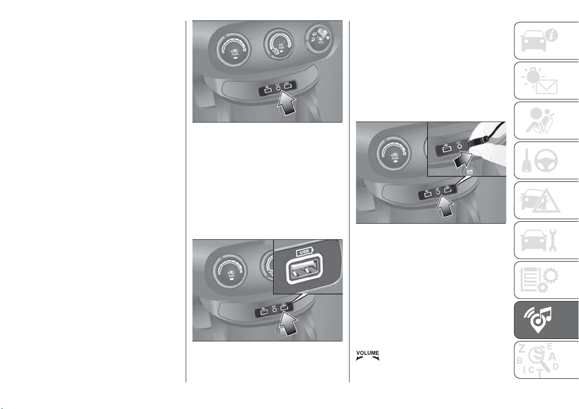
NOTE When modifying the
name-device in the
Bluetooth
®
settings of the phone (where provided),
the Radio may change the track being
played if the device is connected via
USB after the
Bluetooth
®
connection.
After updating the phone software, for
proper operation, it is recommended to
remove the phone from the list of
devices linked to the radio, delete the
previous system pairing also from the
list of
Bluetooth
®
devices on the
phone and make a new pairing.
IMPORTANT If the Bluetooth
®
connection between mobile phone and
system is lost, consult the mobile
phone handbook.
USB SOURCE
To activate the USB mode, insert the
corresponding device into the USB port
on the central tunnel fig. 185.
Some versions feature a second USB
port, located inside the front armrest.
USB charging port
(where provided)
Some versions have a USB charging
port on the central tunnel fig. 186.
When a USB device is inserted with the
radio on, it starts to play the tracks on
the device if the “AutoPlay” is set to
"ON" in the “Audio” menu.
IMPORTANT After using a USB
recharging socket, we recommend
disconnecting the device (smartphone),
always removing the cable from the
vehicle socket first, never from the
device fig. 187. Cables left flying or
connected incorrectly could
compromise correct recharging and/or
the USB socket condition.
AUX SOURCE
(where provided)
To activate AUX mode, insert an
appropriate device in the AUX socket in
the car.
When a device is inserted using the
AUX output socket the system starts
reproducing the AUX source
connected, if it is already being played.
Adjust the volume using the
button/knob on the front panel
or using the volume adjustment control
on the connected device.
185
F1B0238C
186
F1B0212C
187
F1B0383C
253

The "AUX Volume Offset" function can
be selected in “Audio” settings only
when the AUX source is active.
IMPORTANT NOTES
The functions of the device connected
with the AUX socket are directly
managed by the device itself: it is not
possible to change track/folder/playlist
or control playing start/end/pause with
the controls on the front panel or on the
steering wheel.
To avoid possible speaker noise, do not
leave the cable of the portable reader
connected to the AUX socket after
disconnection.
PHONE MODE
Phone mode activation
Press the “Phone” button on the display
to activate the Phone mode.
NOTE To consult the list of mobile
phones and supported functions, visit
the www.driveuconnect.eu website
Use the buttons on the display to:
dial the phone number (using the
graphic keypad on the display);
display and call the contacts in the
mobile phone phonebook;
display and call contacts from the
registers of previous calls;
pair up to 10 phones/audio devices
to make access and connection easier
and quicker;
transfer calls from the system to the
mobile phone and vice versa and
deactivate the microphone audio for
private conversations.
The mobile phone audio is transmitted
through the vehicle’s audio system; the
system automatically mutes the radio
when the Phone function is used.
Pairing a mobile phone
IMPORTANT Carry out this operation
only with vehicle stationary and in safety
conditions; this function is deactivated
when the vehicle is moving.
The pairing procedure for a mobile
phone is described below: always
consult the handbook for the mobile
phone in any case.
To pair the mobile phone, proceed as
follows:
activate the Bluetooth
®
function on
the mobile phone;
press the “Phone” button on the
display;
if no phone is paired with the system
yet, the display shows a dedicated
screen;
access “Settings” and select “Add
device” to start the pairing procedure,
then search for the Uconnect™ device
on the mobile phone;
when prompted by the mobile
phone, use its keypad to enter the PIN
code shown on the system display or
confirm on the mobile phone the PIN
displayed;
during the pairing stage a screen is
displayed showing the progress of the
operation;
when the pairing procedure is
completed successfully, a screen is
displayed: answer “Yes” to the question
to pair the mobile phone as favourite
(the mobile phone will have priority over
all other mobile phones to be paired
subsequently). If no other devices are
paired, the system will consider the first
associated device as favourite.
NOTE After updating the phone
software, for proper operation, it is
recommended to remove the phone
from the list of devices linked to the
radio, delete the previous system
pairing also from the list of
Bluetooth
®
devices on the phone and make a new
pairing.
Making a phone call
The operations described below can
only be accessed if supported by the
mobile phone in use. For all functions
available, refer to the mobile phone
owner's handbook.
254
MULTIMEDIA
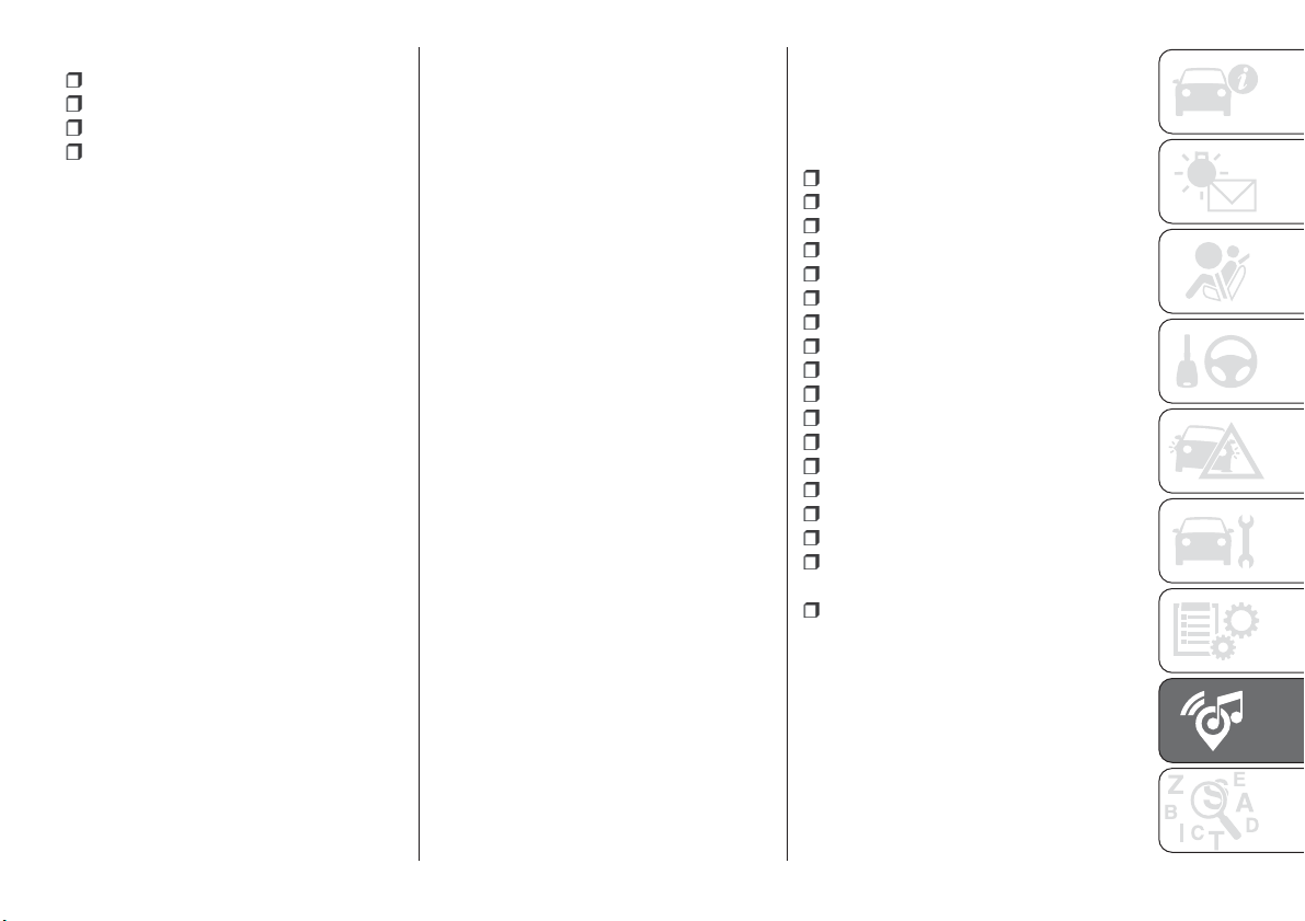
A call can be made by:
selecting "Phonebook";
selecting "Recent";
selecting "Dial";
selecting "Redial".
Favourites
You can add a number or a contact (if
already in Contacts) to the favourite list
during a call by pressing one of the 5
"Empty" graphic buttons on the upper
part of the display. The favourites can
also be managed by using the
Phonebook options
Text message reader
The system can read the messages
received by the mobile phone. To use
this function the mobile phone must
support the SMS exchange function
through
Bluetooth
®
.
If this function is not supported by the
phone, the corresponding "Text" button
is deactivated (greyed out).
When a text message is received, the
display will show a screen where the
options "Read", "Show", "Call" or
"Ignore" can be selected.
Press the "Text Message" graphic
button to access the list of text
messages received by the mobile
phone (the list displays a maximum of
60 messages received).
NOTE On some mobile phones, to
make the SMS voice reading function
available, the SMS notification option
on the phone must be enabled; this
option is usually available on the phone,
in the
Bluetooth
®
connections menu
for a device registered as Uconnect™.
After enabling this function on the
mobile phone, it must be disconnected
and reconnected with the Uconnect™
system in order to make it effective.
IMPORTANT Some mobile phones may
not take the SMS delivery confirmation
settings into account when interfacing
with Uconnect™. If a text message is
sent via the Uconnect™ system, the
driver could face an additional cost,
without any warning, due to the text
message delivery confirmation request
sent by the phone. For any problems
related to the above, contact your
telephone service provider.
"Do not disturb" function
If supported by the connected phone,
by pressing the "Do not disturb"
graphic button the user will not receive
notifications of incoming calls or text
messages. The user can reply with a
default or customised message by
means of the settings.
SMS message options
Default SMS messages are stored in
the system memory and can be sent to
answer a received message or as a
new message.
Yes
No
Okay
I can't talk right now
Call me
I'll call you later
I'm on my way
Thanks
I'll be late
Stuck in traffic
Start without me
Where are you?
Are you there yet?
I need directions
I'm lost
See you later
I will be 5 (or 10, 15, 20, 25, 30, 45,
60) (*) minutes late
See you in 5 (or 10, 15, 20, 25, 30,
45, 60) (*) minutes
(*) Only use the numbers listed,
otherwise the system will not take the
message. When receiving an SMS, the
systems also allows the same message
to be forwarded.
NOTE For details on how to send an
SMS using the voice commands, refer
to the dedicated paragraph.
255

Browsing text messages
(where provided)
Using the steering wheel commands,
you can view and manage the last
10 SMS messages received on the
instrument panel display. To use this
function the mobile phone must
support the SMS exchange function
through
Bluetooth
®
.
Select “Phone” on the instrument panel
Setup Menu and then select “SMS
reader” using the steering wheel
controls. The "SMS reader" submenu
allows the last 10 SMS messages to be
displayed.
Browsing favourites
(where provided)
Using the steering wheel commands,
you can view and manage your
favourite phone numbers on the
instrument panel display. To use this
function, the mobile phone must
support SNS exchange via
Bluetooth
®
and the favourite numbers
must have been saved previously as
such in the Uconnect™ system.
Use the steering wheel controls to
select “Phone” on the instrument panel
Setup Menu. If the phone is connected,
select the "Favourite numbers" option:
the "Favourite numbers" submenu
enables you to view and select the
favourite number.
If the "Phone" option is selected with
the phone not connected, the list of
favourite numbers cannot be viewed.
Uconnect™ LIVE
SERVICES
Press the Uconnect™ button to
access the Uconnect™LIVE
applications.
The application functions are present
according to the vehicle configuration
and to the market.
To use the Uconnect™LIVE services,
you need to download the
Uconnect™LIVE App from Google
Play or Apple Store and register using
the app or on www.driveuconnect.eu
First access to the car
After starting the Uconnect™LIVE
App and entering your credentials, to
access the Uconnect™LIVE App
services in the car you need
Bluetooth
®
pairing between your
smart phone and the Unconnect
™system as described in the
"Registering your cell phone" chapter.
The list of supported mobile phones is
available on www.driveuconnect.eu
After pairing, press the
Uconnect™LIVE button on the display
to access the connected services.
Before using the connected services,
you must complete the activation
procedure following the instructions that
appear in the Uconnect™LIVE App
once the
Bluetooth
®
pairing has been
completed
Uconnect™ LIVE services setup
using the Uconnect™ system
Through the Uconnect™ LIVE
services you can access the "Settings"
section by pressing the
icon. You
can then check the system options and
change them according to your
preferences .
System updates
If an update for the Uconnect™LIVE
system is available while the
Uconnect™LIVE services are being
used, the driver will be informed with a
message on the display of the system.
Connected services that can be
accessed on the car
The eco:Drive™applications and
my:Car applications are developed to
improve the customer's driving
experience, and they are therefore
usable in all the markets where the
Uconnect™LIVE services are
accessible.
On Uconnect™ 7” HD Nav LIVE
versions, the access to
Uconnect™LIVE services enables the
use of “LIVE” services.
256
MULTIMEDIA
eco:Drive™
The eco:Drive™ application allows you
to display your driving behaviour in real
time, in order to help you achieve a
more efficient driving style as far as
consumption and emissions are
concerned.
In addition, the data can be saved on a
USB flash drive, and the data analysis
can be made on your personal
computer thanks to the eco:Drive™
desktop application, available on
www.fiat.it (for Italy) or www.fiat.com
(for other countries) or
www.driveuconnect.eu
Driving style is evaluated by means of
four indices which monitor the following
parameters:
Acceleration
Deceleration
Transmission
Speed
Display of the eco:Drive™
Press the eco:Drive™ button to
interact with the function. A screen will
be displayed showing the 4 indices
described above.
These indices are grey until the system
has enough data to evaluate the driving
style. Once sufficient data are available,
the indices will have 5 colours
depending on the evaluation: dark
green (very good), light green, yellow,
orange and red (very bad).
In the event of extended inactivity the
display will show the average of the
indices up to that moment (“Average
index”) then the indices will be coloured
again in real time as soon as the car is
restarted.
Recording and transferring trip data
The trip data can be stored in the
system memory and transferred
through a properly configured USB
memory stick or by the
Uconnect™LIVE App. This allows you
to display the history of the collected
data, showing the complete analysis of
the trip data and of your driving style.
For further information visit the
www.driveuconnect.eu website
IMPORTANT Do not remove the USB
memory stick nor unpair the
smartphone and the Uconnect™LIVE
App before the system has
downloaded the data, since these
could be lost. During the transfer of
data to the devices, Uconnect™
messages may appear on the display
to guide the user correctly through the
operation; follow these instructions.
These messages are only displayed
with the ignition device at STOP and
when a delay in the Uconnect™
system switching off is set. The data
are automatically transferred to the
devices when the engine is switched
off. Transferred data will be deleted
from the system memory in this
manner. You can choose to store the
trip data or not, by pressing the
"Settings" button and by setting the
storage activation and the transfer
mode (USB or Cloud), as required.
When the USB memory stick is full, the
dedicated messages are shown on the
Uconnect™ system display.
When the eco:Drive™ data have not
been transferred to the USB key for a
while, the Uconnect™ system internal
memory could become saturated: in
this case, follow the recommendations
provided by the messages on the
display.
my:Car
my:Car allows you to keep the
condition of your car always under
control. The my:Car application is
capable of detecting malfunctioning in
real time and lets the driver know about
the expiry of maintenance coupons, To
interact with the application, press "
my:Car" button: a screen will appear
on the display showing the "care:Index"
section which contains detailed
information on car status. Press the
"Active warnings" button to show the
details of any faults on the car which
caused a warning light to switch on.
257

The car status can be seen both on
www.driveuconnect.eu or through the
Uconnect™LIVE App.
Apple CarPlay and
Android Auto
(where provided)
The Apple CarPlay and Android Auto
applications allow you to use your
smartphone in the car safely and
intuitively. To enable them, just connect
a compatible smartphone via the USB
port and the phone's contents will be
automatically shown on the
Uconnect™ system display.
To check the compatibility of your
smartphone, see the indications on the
websites:
https://www.android.com/intl/it_it/auto/
and http://www.apple.com/it/ios/
carplay/.
If the smartphone is connected
correctly to the car via the USB port,
the Apple CarPlay or Android Auto icon
will be displayed in place of the
button in the main menu.
Android Auto APP Setup
Before use, download the Android Auto
application to your smartphone from
Google Play Store.
The application is compatible with
Android 5.0 (Lollipop) and later
versions. To use Android Auto, the
smartphone must be connected to the
car with a USB cable.
On the first connection, you will have to
perform the setup procedure that
appears on the smartphone. You can
only perform this procedure with the
vehicle stationary.
Once connected to the USB port, the
Android Auto application establishes a
parallel
Bluetooth
®
connection.
Apple CarPlay App Setup
Apple CarPlay is compatible with the
iPhone 5 or more recent models, with
the iOS 7.1 operating system or later
versions. Before using Apple CarPlay,
enable Siri from Settings > General >
Siri on the smartphone.
To use Apple CarPlay, the smartphone
must be connected to the car with a
USB cable.
NOTE Enabling CarPlay/Android Auto
or some functions could require
interaction on the smartphone. If
necessary, complete the step on your
device (smartphone).
Interaction
After the setup procedure, on
connecting your smartphone to the
car's USB port, the application will run
automatically on the Uconnect™
system.
You can interact with Apple CarPlay
and Android Auto using the steering
wheel button
(long press of the
button), using the SCROLL TUNE
button/knob (to select and confirm) or
using the Uconnect™ system
touchscreen.
Navigation
With the Apple CarPlay and Android
Auto applications, the driver can
choose to use the navigation system on
their smartphone.
If the system “Nav” mode is already
active, or when a device is connected
to the car with a navigation session in
progress, the Uconnect™ display
shows a pop-up alert enabling the
driver to choose between system
navigation or navigation using the
smartphone.
The selection can be changed at any
time by accessing the chosen
navigation system and setting a new
destination.
258
MULTIMEDIA
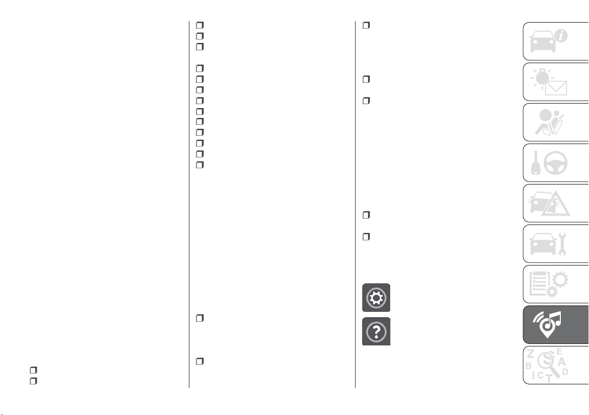
Setting “AutoShow smartphone
display on connection"
Through the Uconnect™ system
settings, the user can decide to view
the smartphone screen on the
Uconnect™ system display as soon as
the smartphone is connected via the
USB port.
When this function is set, each time a
connection is made via USB, the Apple
CarPlay or Android Auto apps will run
automatically on the Uconnect™
system display.
The "AutoShow smartphone display on
connection" item can be found in the
"Display" submenu. The function is
enabled by default.
Exiting the Android Auto and Apple
CarPlay apps
To end the Apple CarPlay or Android
Auto session, physically disconnect the
smartphone from the car's USB port.
SETTINGS
Press the “Settings” button on the
display to show the main “Settings”
menu.
NOTE The menu items displayed vary
according to the versions.
As a guideline, the menu includes the
following items:
Display
Units (where provided)
Voice commands
Time and Date;
Safety/Driving assistance (where
provided)
Lights
Doors & Locks
Engine Off Options
Audio
Telephone/Bluetooth
®
Radio Setup
SiriusXM Setup (where provided)
Restore Default Settings
Clear Personal Data
Apps restore (where provided)
NAVIGATION
(versions with Uconnect™ 7" HD Nav
LIVE only)
Press the "Nav" button to show the
navigation map on the display.
NOTE: The navigation system volume
can only be adjusted during navigation
when the system provides voice
indications.
Navigation main menu
In the navigation view, tap the "Main
menu" button to open the menu:
Select the "Search" button to search
for an address, a place or a point of
interest, then plan a route to the
location.
Select the "Current trip" button to
delete or edit the planned route.
Select the "My places" button to
create a collection of useful or preferred
addresses. The following items are
always available in "My places": “Home”
and “Recent destinations”.
Select the "Parking" button to search
for car parks.
Select the "Weather" or "Speed
Camera Warning" button to receive
information on the weather or warnings
about speed camera locations.
NOTE The "Weather" and "Speed
Camera Warnings" functions are only
active if TomTom Services are activated.
Otherwise, the button will appear
greyed out (and the functions will not
be available).
Select the "Petrol Station" button to
search for petrol stations.
Select the "TomTom Services" button
to view the activation state of the
following services (subscription
needed): “Traffic”, “Speed cameras”,
“Weather”, “Online search”.
Select this button to open the
"Settings" menu.
Select this button to open the
"Help" menu. The "Help"
menu contains information on
the Uconnect™ system, for
example the map version, the
serial number of the device
and the legal notices.
259
Select this button to return to
the map display or navigation
view.
Select this button to
activate/deactivate voice
instructions. Select off to no
longer hear voice instructions.
You will still receive information
such as traffic information and
warning sounds. Tip: you can
deactivate the warning sounds
by selecting “Settings”, then
“Sounds and warnings”.
Select this button to
increase/decrease the screen
brightness and display the
map in brighter/darker colours.
When driving at night or in unlit
tunnels, watching the screen is
more comfortable and less
distracting for the driver if the
map uses darker colours. Tip:
the device will automatically
switch between day and night
view depending on the time of
day. To deactivate this
function, select “Appearance”
in the “Settings” menu and
deselect the option "Switch to
night colours" when it is dark.
Map update
To ensure optimal performance, the
navigation system must be updated
periodically. For this, the Mopar Map
Care service offers a new map update
every three months.
The updates can be downloaded from
the maps.mopar.eu website and
installed directly on the navigator in your
car. All updates are free of charge for
3 years from the start of the warranty
on the car.
The navigation system can also be
updated at the Fiat Dealership.
NOTE The dealer may charge for
updating the navigation system.
VOICE COMMANDS
Note For languages not supported by
the system, voice commands are not
available.
To use the voice commands, press the
button on the steering wheel (”Voice”
button) and say out loud the command
you want to activate.
Global voice commands
The following voice commands can be
given after pressing the
button on
the steering wheel:
Help
Cancel
Repeat
Voice Prompts
Phone voice commands
The following voice commands can be
given after pressing the
button on
the steering wheel:
Call
Dial
Re-dial
Call back
Recent calls
Calls made
Missed calls
Calls received
PhoneBook
Search
Show SMS
Send an SMS
Show messages
Radio voice commands
The following voice commands can be
given after pressing the
button on
the steering wheel:
Tune to FM "frequency"
Tune to AM "frequency"
Tune to "radio name" FM
Media voice commands
The following voice commands can be
given after pressing the
button on
the steering wheel:
Play song...
Play album…
Play artist…
Play genre…
Play playlist…
260
MULTIMEDIA
Play podcast…
Play audiobook…
Select the source...
View...
Navigation voice commands
(versions with Uconnect™ 7" HD Nav
LIVE only)
The following voice commands can be
given after pressing the
button on
the steering wheel:
Find "POI"
"Go to" “address”
Go to "city name" centre
Drive towards a town centre
Navigate home
Go via home
Cancel Route
Add this position to “My places”
Display “My Places”
Navigate through a saved location
Recent Destinations
Stop at a recent destination
Zoom in
Zoom out
2D view
3D view
Report Speed Camera
Report risk area
MOPAR
®
CONNECT
(where provided)
These services let you keep your
vehicle under control at all times and
receive assistance in the event of
accident, theft or breakdown.
To have these services, install the
Mopar
®
Connect Device on your
vehicle from the country (list
available on the
www.driveuconnect.eu website)
and request activation by following
the instructions received at the
email address given when your
vehicle was handed over to you.
To use the connected services, you
must download the Uconnect™LIVE
App or access the
www.driveuconnect.eu portal.
You can find all the details about the
services in the Mopar
®
Connect
section of the
www.driveuconnect.eu portal.
PRIVACY MODE
Privacy mode lets you disable the “Find
car”, “Notify Area” and “Notify Speed”
services, which allow registered
customers to locate their cars, for a
fixed time.
IMPORTANT Vehicle position tracing
remains active for the assistance
services, where provided, in the event
of accident or vehicle theft, but is not
visible to the customer.
PRIVACY MODE activation
procedure
Proceed as follows:
take note of the total odometer
reading;
make sure that the instrument panel
is off;
Send the following text message to
+393424112613: “PRIVACY
<VEHICLE_CHASSIS_NUM>
<TOTAL_MILEAGE_KM>” (e.g.:
PRIVACY
ZFA3340000P123456 12532). You can
find the chassis number in the
registration document;
before starting the engine, wait to
receive the text message confirming
that Privacy mode has been activated
and indicating when it expires.
When you have received the
confirmation, you can start your trip in
the knowledge that the vehicle will not
be traced until the indicated expiry time.
If it expires while you are still travelling,
Privacy mode will be extended until you
turn off the engine (instrument panel
off).
261

If you receive a text message indicating
that your request was not successful,
you must be aware that the vehicle will
continue to be visible to the registered
customer.
If you have any doubts or problems
during activation, consult the FAQ on
the www.driveuconnect.eu portal,
contact the Fiat Dealership or contact
Customer Care.
OFFICIAL TYPE
APPROVALS
All radio equipment supplied with the
vehicle complies with the 2014/53/EU
directive.
For further information visit the
www.mopar.eu/owner or
http://aftersales.fiat.com/elum/
websites
262
MULTIMEDIA
IMPORTANT INFORMATION AND RECOMMENDATIONS
WARNING
INTERIOR FITTINGS
Do not travel with the storage compartment open: it may injure the front seat occupants in the event of an accident.
The cigar lighter gets extremely hot. Handle it carefully and make sure that children don’t use it: risk of fire and/or burns.
Do not use the ashtray as a waste paper basket: it may catch fire in contact with cigarette stubs.
ROOF RACK/SKI RACK
Before driving, make sure that the transversal bars have been fitted properly.
ENVIRONMENTAL PROTECTION SYSTEMS
The catalytic converter and particulate filter (DPF) reach very high temperatures during operation. Therefore do not park the vehicle on
flammable materials (e.g. grass, dry leaves, pine needles, etc.): fire hazard.
IMPORTANT
ROOF RACK/SKI RACK
The use of transversal bars on longitudinal ones prevents the use of the sunroof, because the latter, while opening, interferes with the bars.
Therefore do not move the sunroof if transversal bars have been fitted.
Fully comply with the regulations in force concerning maximum clearance.
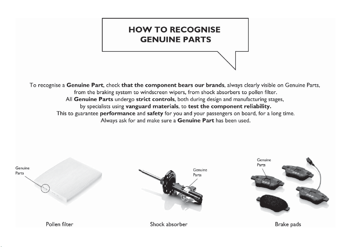
Mopar Vehicle Protection offers a series of service contracts that are designed to give all our customers the
pleasure of driving their vehicle without any hitch's and concerns.
Our product portfolio consists of a wide and flexible range of extended warranty and maintenance plans
endorsed by FCA. Each with a series of different coverage tiers, in terms of durability and mileage, built to
accommodate you’re driving needs.
Service contracts are made by experts that know every part of your vehicle, and commit themselves
to maintain it in tip top conditions. Our knowledge and passion is tailored around designing
products that promises all our drivers “worry-free driving”.
Only with Mopar Vehicle Protection you are ensured that all service operations are performed
by highly qualified and specialized technicians in authorized FCA repair facilities, using the right tools,
equipment and only original parts, all over Europe.
Check which Service Contract plans are available on your market today and choose the
Service Contract that suits your driving habits best.
Ask your local dealer for further information.
MAINTAIN YOUR VEHICLE IN
TIP TOP CONDITIONS WITH

INDEX
ABS (system) ...............74
Active safety systems...........74
Adaptive Cruise Control ........129
Airbag
Front airbags .............106
Side bags ...............110
Airbags (SRS supplementary
restraint system) ...........106
Alarm .....................14
Automatic dual zone climate
control system .............35
Automatic light control (AUTO
function) .................25
Automatic main beam headlights . . .27
Automatic transmission.........119
Automatic transmission - key
removal .................169
Automatic transmission - lever
unlock..................168
Battery ..................195
advice for extending its life .....195
replacement ..............195
Battery recharging ............197
Blind Spot Assist System ........78
Bodywork (cleaning and
maintenance) .............203
Bonnet ....................40
Boot .....................41
Boot (extension) ..............20
Brakes
brake fluid level ............194
Bulbs
types of bulbs ............149
Carrying children safely .........93
Changes/alterations to the car ......5
Changing a wheel ............159
Checking levels..............187
Child restraint systems ..........93
Child safety device ............18
Climate control system ..........33
CO2 emissions ..............229
Colour display ...............48
Control buttons ..............49
Control panel and on-board
instruments ...............47
Daytime running lights (DRL)......26
Dead Lock (device) ............17
Dimensions................213
Dipped beam headlights.........25
Dipped/main beam headlights
(bulb replacement) ..........151
Direction indicators ............28
Display ....................49
Doors.....................15
Driving assistance systems .......78
DST (system) ................76
DTC (system) ................74
Dual clutch automatic
transmission - lever unlock .....170
Dual clutch automatic
transmission - removing the
key....................171
Electric Parking Brake (EPB) .....115
Electric sun roof ..............38
Electric windows..............37
Electrically adjustable front seats....19
Electronic Cruise Control........127
Emergency starting ...........166
Engine ...................208
engine coolant level .........194
marking ................207
Engine compartment ..........187
Engine compartment (washing). . . .204
Engine oil
consumption .............194
level check ..............194
EPB (Electric Parking Brake) .....115
ERM (system)................76
ESC (system) ................74
Exterior lights ................25
Fiat Code (system) ............14
Fix&Go Automatic kit ..........163
Fluids and lubricants ..........222
Fog lights ..................26
Fog lights (bulb replacement) .....151
Follow Me Home .............26

Front roof light ...............29
Front seat electric heating ........20
Front seats (manual adjustments) . . .19
Fuel consumption ............226
Fuel cut-off system ...........168
Full Brake Control (system) .......80
Fuse boxes ................154
Fuses (replacement)...........154
GSI (Gear Shift Indicator) ........49
Hazard warning lights .........148
emergency braking .........148
Head restraints...............21
Headlight alignment adjustment ....28
Headlight alignment corrector .....28
Headlights (cleaning) ..........203
Heavy-duty use of the car
(scheduled servicing) ........186
HHC (system)................75
i-Size child restraint systems .....100
Identification data
chassis marking ...........207
engine marking ............207
VIN plate ................207
Ignition device ...............12
Important information and
recommendations ..........263
Interior lights ................29
Interiors (cleaning) ............204
ISOFIX child restraint system
(installation) ...............97
iTPMS (indirect Tyre Pressure
Monitoring System) ..........84
Jump starting ..............166
Keyless Entry (system) .........16
Keys
electronic key .............11
key with remote control .......11
Lane Assist system...........137
Lane Change ................28
Lifting the vehicle.............201
Light switch .................25
Main beam headlights..........27
Main menu .................50
Manual climate control system .....33
Manual gearbox .............118
Monochrome display ...........47
Mood Selector / Drive Mode
(drive mode selector) ........133
Mopar Connect .............261
Number plate lights (bulb
replacement)..............153
Occupant protection systems .....87
Official type approvals .........262
Paintwork (cleaning and
maintenance) .............203
Park Assist (system)...........135
Parking lights ................26
Parking the vehicle ...........115
PBA (system) ................75
Performance (top speed)........225
Periodic checks (scheduled
servicing) ................186
Pre-tensioners ...............91
load limiters ...............91
Prescriptions for handling the car
at the end of its life ..........231
Rain sensor ................30
RCP system ................79
Read this carefully..............2
Rear fog light ................26
Rear light cluster (bulb
replacement)..............152
Rear seats..................20
Rear view camera ............139
Rear View Camera............139
Rear view mirrors .............23
Rear window washer
windscreen/rear window
washing fluid level ..........194
Rear window wiper/washer .......32
Reconfigurable load platform ......42
Refuelling procedure ..........145
emergency refuelling ........145
Refuelling the vehicle ..........144
Replacing a bulb .............148
Replacing an external bulb ......151
Rims and tyres (dimensions)......211
INDEX

SBR (Seat Belt Reminder)
system ..................89
Scheduled Servicing ..........175
Scheduled Servicing Plan . . . .176 ,180
Screen wiper/washer ...........29
Seat belts ..................87
Seats .....................19
Service Position (windscreen
wiper) ...................31
Servicing procedures ..........198
Side bag ..................110
Side direction indicators (bulb
replacement)..............152
Side lights/daytime running lights
(DRL) (bulb replacement) ......151
Smart washing function .........30
Snow chains ...............201
Speed Limiter...............127
Start&Stop system ...........125
Starting the engine ...........114
Steering lock ................13
Steering wheel ...............23
Supplies ..................218
Symbols....................4
TC (system) ................75
Technical specifications ........207
The keys...................11
Third brake light (bulb
replacement)..............153
Tips, controls and general
information ...............233
Towing the vehicle ............172
Towing trailers ..............140
Trip Computer ...............51
TSC (system) ................76
Twin clutch automatic
transmission ..............122
Tyres (inflation pressure) ........212
Uconnect™ 7” HD LIVE /
Uconnect™ 7” HD Nav LIVE. . . .245
Uconnect™ Radio ............235
Use of the owner handbook .......6
Version with LPG system ........43
Warning lights and messages .....52
Weights ..................215
Wheels and tyres.............201
Window bag ...............110
Windows (cleaning) ...........203
Windscreen/rear window wiper ....29

FCA Italy S.p.A. - MOPAR - Technical Services - Service Engineering
Largo Senatore G. Agnelli, 3 - 10040 Volvera - Turin (Italy)
Print no. 603.91.552 - 11/
2017 - 1 Edition

Nosotros, que hemos creado, diseñado y fabricado tu automóvil,
lo conocemos realmente hasta el más mínimo detalle y componente.
En los talleres autorizados Fiat Service encontrarás a técnicos formados directamente por nosotros
que te ofrecen calidad y profesionalidad en todas las intervenciones de mantenimiento.
Los talleres Fiat siempre están a tu lado para realizar el mantenimiento periódico,
las revisiones estacionales y brindarte consejos prácticos de nuestros expertos.
Utilizando los Recambios Originales distribuidos por MOPAR
®
, las características de fiabilidad,
confort y prestaciones por las que has elegido tu nuevo vehículo se conservan a lo largo del tiempo.
Te recomendamos solicitar siempre Recambios Originales, ya que son el resultado de nuestro esfuerzo
constante en la búsqueda y el desarrollo de tecnologías cada vez más innovadoras.
Por todos estos motivos elige Recambios Originales:
los únicos especialmente diseñados por FCA para tu automóvil.
SEGURIDAD:
SISTEMA DE FRENOS
ECOLOGÍA: FILTROS ANTIPARTÍCULAS,
MANTENIMIENTO DEL CLIMATIZADOR
CONFORT: SUSPENSIONES
Y LIMPIAPARABRISAS
PRESTACIONES:
BUJÍAS, INYECTORES Y BATERÍAS
LINEACCESSORI:
BARRAS PORTA TODO, LLANTAS
POR QUÉ ELEGIR
RECAMBIOS ORIGINALES

Los datos contenidos en esta publicación son a título indicativo.
FCA Italy S.p.A. podrá modificar en cualquier momento los modelos descritos en esta publicación por razones técnicas o comerciales.
El Cliente puede solicitar más información en los concesionarios de la Red de Asistencia Fiat.
Impreso en papel ecológico sin cloro.
ESPAÑOL