
Loading ...
Loading ...
Loading ...
Page 8 of 16 Zip HydroTap Installation and Operating Instructions - 89585 - March 2016 v2.03
Installation Procedure continued
Step B - Installing the undersink unit
SPECIAL NOTE: The HydroTap undersink units are heavy, take note of the
weights listed in the table on page 6. If you think you cannot lift the unit
safely, get help and avoid possible injury.
Position the Zip HydroTap undersink unit as close as possible to directly beneath the
Zip HydroTap tap head.
The connection tubes supplied with the tap head assembly CANNOT be lengthened.
Allow at least a 65 mm air-gap to the LHS for air circulation
Note:
Included in the installation pack are adhesive backed silicon buffers. If air vents are
not installed in the cupboards housing the HydroTap, the buffers must be placed on
the inside edge of the cupboard door to create a slight gap ensuring a minimum
airflow. Failure to do this may cause the HydroTap to overheat and operate
inefficiently.
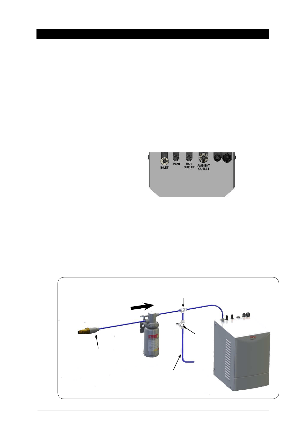
Step C - Installing the filter
The Miniboil is supplied with an external filter (see diagram below). It is important
the filter be securely fixed adjacent to the under sink unit in such a manner as to
allow for easy access to the filter, for service and regular replacement.
The ¼” tube supplied must be carefully measured and cut to allow for the
connection of the filter, double check valve and JG fittings.
Filter assembly sequence: (see fig.1)
This instruction is critical :
Adjust both cupboard door hinges and
attach the supplied rubber door buffers to
the doors to create a 4 mm air-gap
between the doors and the cupboard. This
is the minimum ventilation requirement
for low usage installations.
Proper air circulation is important for
efficient running of the Hydrotap models.
Therefore cupboard ventilation for
Hydrotap models is recommended.
Connection as viewed from the top
Flow Direction
Pressure Limiting Valve
External Filter Connection Fig. 1
Flush Tube
Tee Piece
Flush Valve
Loading ...
Loading ...
Loading ...