

OWNER HANDBOOK
cop lum Stelvio GB.indd 1 15/11/16 12:52

This Owner Handbook illustrates the operating instructions of the car.
Alfa Romeo provides a dedicated section available in electronic format for
enthusiasts who want insights, curiosities and detailed information about the features and functions of the car.
ONLINE OWNER HANDBOOK
The symbol appears in the Owner Handbook next to topics for which updates are available.
Go to elum.alfaromeo.com.
website and access your personal area.
The “Maintenance and care” page includes all the information about your vehicle and the link to access eLUM, where you will find all the details of the Owner Handbook.
Alternatively, to access this information, go to the Internet website at http://aftersales.fiat.com/elum/
.
The eLUM website is free and conveniently allows you to browse the on-board documents of all other models of the Group, among many other things.
Have a nice read and happy motoring!

Dear Customer,
We would like to congratulate and thank you for choosing an Alfa Romeo.
We have written this handbook to help you get to know all the features of your car and use it in the best possible way. This car is
intended for daily use as well as for specific uses. Please take your time to familiarise with all the dynamic features of your car.
Here you will find information, advice and important warnings regarding use of your vehicle and how to achieve the best performance
from the technical features of your Alfa Romeo.
You are advised to read it right through before taking to the road for the first time, to become familiar with the controls and above
all with those concerning brakes, steering and gearbox; at the same time, you can understand the vehicle behaviour on different road
surfaces.
This document also provides a description of special features and tips, as well as essential information for the safe driving, care and
maintenance of your Alfa Romeo over time.
After reading it, you are advised to keep the handbook inside the vehicle, for an easy reference and for making sure it remains on
board the vehicle should it be sold.
In the attached Warranty Booklet you will also find the description of the Services that Alfa Romeo offers to its customers, the
Warranty Certificate and the detail of the terms and conditions for maintaining its validity.
We are sure that these will help you to get in touch with and appreciate your new car and the service provided by the people at Alfa
Romeo.
Enjoy reading. Happy motoring!
IMPORTANT
This Owner Handbook describes all car versions. Optional contents, equipment meant for specific Markets or particular versions
are not identified as such in the text: you need to consider only the information related to the version you own. Any content
introduced throughout the production of the model, outside the specific request of options at the time of purchase, will be
identified with the wording (where provided).
All data contained in this publication are intended to help you use your vehicle in the best possible way.
Alfa Romeo S.p.A. aims at a constant improvement of the vehicles produced. For this reason it reserves the right to make changes
to the model described for technical and/or commercial reasons.
For further information, contact an Alfa Romeo Dealership.

READ THIS CAREFULLY
REFUELLING
Petrol engines: only refuel with unleaded petrol with octane rating (RON) not less than 95 in compliance with the European specification EN228. Do not use
petrol containing methanol or ethanol E85. Using these mixtures may cause misfiring and driving issues, as well as damage vital components of the supply
system.
Diesel engines: refuel only with Diesel fuel motor vehicles conforming to the European specification EN590. The use of other products or mixtures may
damage the engine beyond repair and consequently invalidate the warranty, due to the damage caused.
For further details on the use of the correct fuel see the "Refuelling the car" paragraph in the"Starting and driving" chapter.
STARTING THE ENGINE
Make sure that the electric parking brake is engaged and that the transmission is in P (Park) or N (Neutral), press the brake pedal and then press the ignition
device button.
PARKING ON FLAMMABLE MATERIAL
The catalytic converter develops high temperatures during operation. Do not park the car on grass, dry leaves, pine needles or other flammable material: fire
hazard.
RESPECTING THE ENVIRONMENT
The vehicle is fitted with a system that carries out a continuous diagnosis of the emission-relatedcomponents in order tohelp protect the environment.
ELECTRICAL ACCESSORIES
If, after buying the vehicle, you decide to add electrical accessories (with the risk of gradually draining the battery), contact an Alfa Romeo Dealership. They
can calculate the overall electrical requirement and check that the vehicle's electric system can support the required load.
SCHEDULED SERVICING
Correct maintenance of the car is essential for ensuring that it maintains its performance and its safety features, its environmental friendliness and low
running costs for a long time to come.

"CYBERSECURITY" DEVICES
The car is equipped with security devices developed according to the technological standards currently applied in the automotive industry to protect the
onboard electronic systems from hacking attempts. The purpose of these security devices is to minimise the risk of cyber-attacks or the installation of viruses
or malware which could compromise the performance of the car and/or allow stealing of personal data of the buyers and/or users and/or unauthorised
dissemination of said information.
The car's purchaser must not remove, modify or tamper with these anti-hacking security devices. The Manufacturer will therefore not be liable for negative
consequences and/or damage to the vehicle and/or to the buyer and/or to third parties deriving from the removal, modification or alteration of the security
devices performed by the car's purchaser and/or user.

USE OF THE OWNER HANDBOOK
OPERATING INSTRUCTIONS
Each time direction instructions (left/right or forwards/backwards) about the vehicle are given, these must be understood as regarding an occupant in the
driver's seat. Special cases not complying with this rule will be specified as appropriate in the text.
The figures in the Owner Handbook are provided by way of example only: this might imply that some details of the image do not correspond to the actual
arrangement of your car. In addition, the Handbook has been conceived considering vehicles with steering wheel on the left side; it is therefore possible that on
vehicles with steering wheel on the right side, the position or construction of some controls is not exactly mirror-like withrespect to the figure.
To identify the chapter with the information needed you can consult the index at the end of this Owner Handbook.
Chapters can be rapidly identified with dedicated graphic tabs, at the sideof each odd page. A few pages further there is a key for getting to know the chapter
order and the relevant symbols in the tabs. There is in any case a textual indication of the current chapter at the side of each even page.
WARNINGS AND PRECAUTIONS
While reading this Owner Handbook you will find a series of WARNINGS to prevent procedures that could damageyour vehicle.
There are also PRECAUTIONS that must be carefully followed to prevent incorrect use of thecomponents of the car, which could cause accidents or injuries.
Therefore all WARNINGS and PRECAUTIONS must always be carefully followed.
WARNINGS and PRECAUTIONS are recalled in the text with the following symbols:
personal safety;
vehicle safety;
environmental protection.
NOTE These symbols, when necessary, are indicated besides the title or at the end of the line and are followed by a number.
That number recalls thecorresponding warning at the end of the relevant section.

MULTIMEDIA CONTENT
The description of some features of the car is completed by video support. To view the contents:
check availability on your mobile device of an app for reading QR codes;
scan the QR code located at the relevant topic using your mobile device;
access the video content.
NOTE The multimedia content is only available in some languages.
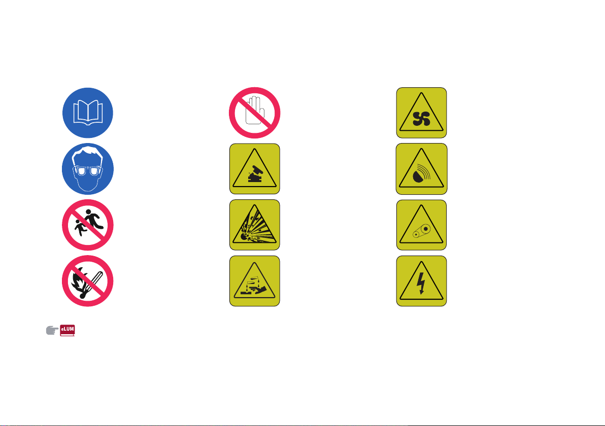
SYMBOLS
Some car components have coloured labels whose symbols indicate precautions to be observed when using this component. See below for a brief description of
each symbol summarising the contents herein. Always take great care to all warnings herein.
READ THE USER'S
MANUAL
DO NOT TOUCH WITH
HANDS
IT CAN START
AUTOMATICALLY ALSO
WITH ENGINE OFF
PROTECT YOUR EYES
DO NOT OPEN THE CAP
WHEN THE ENGINE IS
HOT
DO NOT OPEN: HIGH
PRESSURE GAS
KEEP CHILDREN AT A
DISTANCE
BURSTING
MOVING PARTS KEEP
PARTS OF YOUR BODY
AND CLOTHES AWAY
DO NOT APPROACH
FLAMES
CORROSIVE LIQUID HIGH VOLTAGE
CHANGES/ALTERATIONS TO THE CAR
WARNING Any change or alteration of the car might seriously affect its safety and road holding, thus causing accidents, in which the occupants could even be
fatally injured.

GETTING TO KNOW YOUR CAR
KNOWING THE INSTRUMENT PANEL
SAFETY
STARTING AND DRIVING
IN AN EMERGENCY
MAINTENANCE AND CARE
TECHNICAL SPECIFICATIONS
MULTIMEDIA
CONTENTS


In-depth knowledge of your new vehicle starts here.
The handbook that you are reading simply and directly
explains how it is made and how it works.
That’s why we advise you to read it seated comfortably on
board, so that you can see immediately what is described here
for yourself.
GETTING TO KNOW YOUR CAR
DASHBOARD . . .. . . . . . . . .. . . . . . . . . . .. . . . . . . . .. . . . . . . . .. . . . . . . . .. . . . . . . . . . .. .10
DASHBOARD (RIGHT-HAND DRIVE VERSION) . . .. . . . . . . . .. . . . . . . . . . .. 11
THEKEYS ...................................................................12
IGNITIONDEVICE ..........................................................13
ENGINEIMMOBILIZER....................................................15
ALARMSYSTEM...........................................................15
DOORS ......................................................................16
SEATS .......................................................................19
HEADRESTRAINTS ...................................................... 23
STEERINGWHEEL ........................................................24
REAR-VIEWMIRRORS ................................................... 25
EXTERIORLIGHTS........................................................26
INTERIORLIGHTS ........................................................ 30
WINDSCREENWIPER .................................................... 31
CLIMATECONTROLSYSTEM........................................... 33
ELECTRICWINDOWS ....................................................36
ELECTRICSUNROOF .....................................................37
BONNET....................................................................39
LUGGAGECOMPARTMENTTAILGATE................................ 40
WIRELESS CHARGING SYSTEM - WCPM (Wireless Charge Pad
Module).....................................................................42
GETTING TO KNOW YOUR CAR
10
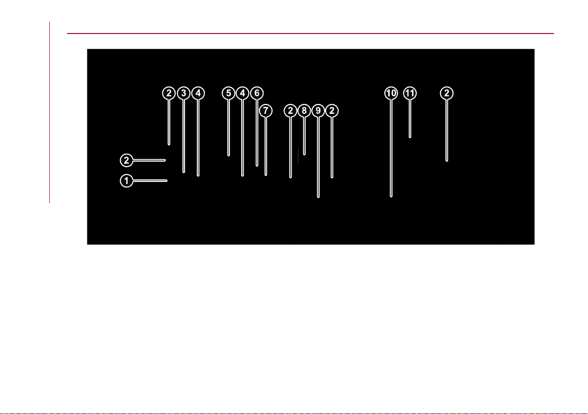
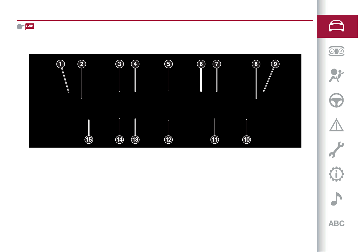
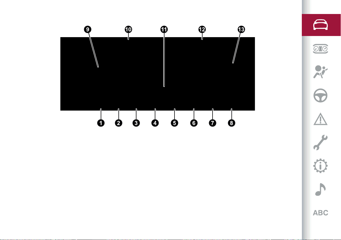
DASHBOARD
1 03036V0088EM
1. Light switch / 2. Air vents / 3. Left stalk / 4. Controls on the steering wheel / 5. Instrument panel / 6. Steering wheel / 7. Right stalk /
8. Connect / 9. Automatic dual-zone climate control system / 10. Glove compartment / 11. Passenger airbag
11
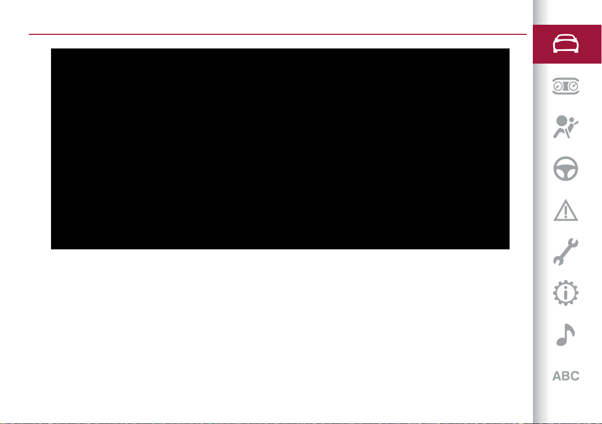
DASHBOARD (RIGHT-HAND DRIVE VERSION)
2
03036V0004EM
1. Light switch / 2. Air vents / 3. Left stalk / 4. Controls on the steering wheel / 5. Instrument panel / 6. Steering wheel / 7. Right stalk /
8. Connect / 9. Automatic dual-zone climate control system / 10. Glove compartment / 11. Passenger airbag / 12. Bonnet release lever
GETTING TO KNOW YOUR CAR
12
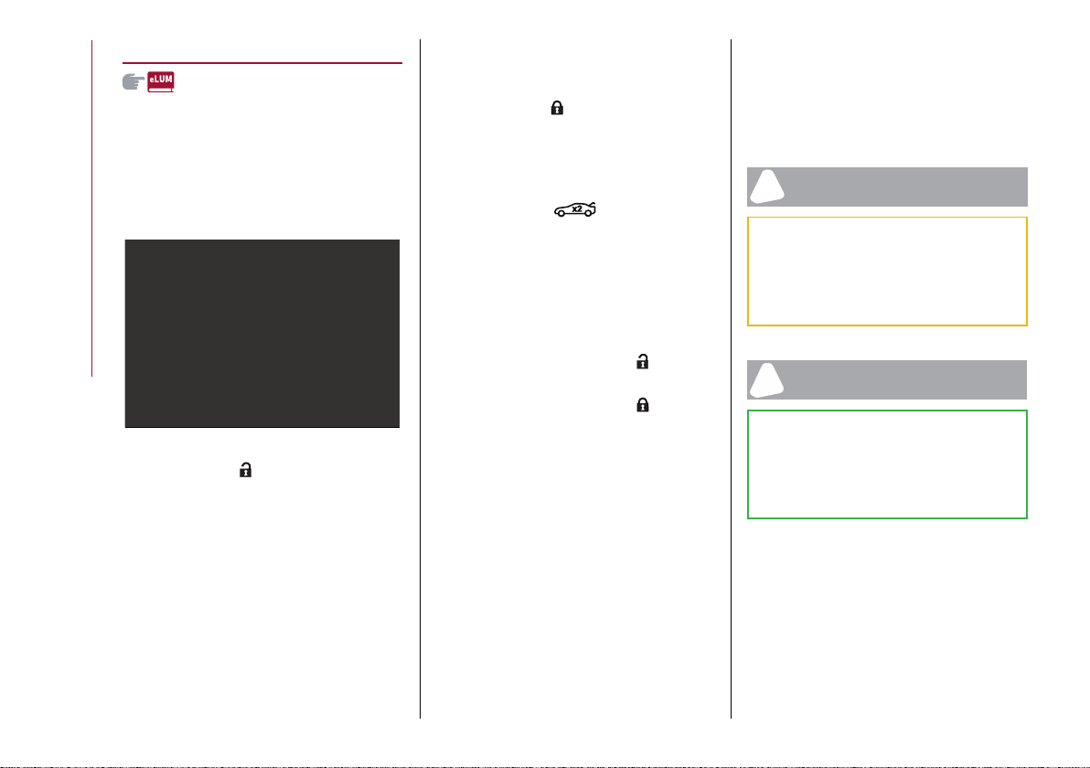
THE KEYS
ELECTRONIC KEY
1)
1)
The vehicle is equipped with an
electronic key with a Keyless Start
function fig. 3, provided in duplicate.
3 04016S0010EM
Briefly press the button: unlocking of
doors and tailgate, timed switching-on
of internal lights and single flashing of
direction indicators (if activated from
the Connect system).
The doors can always be unlocked by
putting the metal insert inside the driver
side door lock.
Briefly press the button: locking of
doors and tailgate, timed switching-off
of internal lights and double flashing of
direction indicators (if activated from
Connect system).
Rapidly press the button twice to
open the tailgate remotely. The direction
indicators will flash twice to indicate that
the tailgate has been opened.
Automatic window opening/closing
function
(where provided)
Prolonged pressing of button : open all
windows.
Prolonged pressing of button : close all
windows.
REQUEST FOR ADDITIONAL KEYS
If you need a new electronic key, go to
an Alfa Romeo Dealership, taking an
ID document and the car ownership
documents.
IMPORTANT
1) The electronic components inside the key
may be damaged if the key is subjected to
strong shocks. In order to ensure complete
efficiency of the electronic devices inside
the key, it should never be exposed to direct
sunlight.
IMPORTANT
1) Used batteries may be harmful to the
environment if not disposed of correctly.
They must be disposed of as specified by
law in the special containers or taken to an
Alfa Romeo Dealership, which will take care
of their disposal.
13
IGNITION DEVICE
OPERATION
1) 2) 3) 4) 5)
To activate the starter switch fig. 4
the electronic key must be inside the
passenger compartment.
4 04026V0001EM
The ignition device has the following
possible states:
STOP: engine off, steering locked.
Some electrical devices (e.g. central
door locking system, alarm, etc.) are still
available;
ON (single button press): all electrical
devices are available. This state can be
selected by pressing the ignition device
button once, without pressing the brake
pedal;
AVV: engine starting. This state can be
selected by pressing the starter button
once with the brake pedal pressed.
NOTE With the starter switch ON, if
30 minutes pass with P (Park) mode
engaged and the engine stopped, the
starter switch will automatically move to
the STOP position.
NOTE With the engine running, it is
possible to go away from the car taking
the electronic key with you. The engine
will still be running. The vehicle will
indicate the absence of the key on board
when the door is closed.
For more information on the engine
start-up, see the description in the
"Starting the engine" paragraph, in the
"Starting and driving" chapter.
WARNING If the battery was
disconnected, do not start the engine
immediately after reconnecting the
terminals, but press the start button,
without operating the pedals, to turn on
the instrument panel and then start the
engine.
The
symbol on the instrument panel
will remain on, indicating that the
steering must be initialised. To do this,
turn the steering wheel from one end to
the other and bring it back to the centre
position within 30 seconds from starting
the engine. If any red warning lights on
the instrument panel remain lit, stop the
engine, wait for at least 5 seconds and
repeat the starting procedure described
above.
GETTING TO KNOW YOUR CAR
14
STARTING WITH FLAT KEY BATTERY
If the remote control battery is flat,
proceed as follows to start the car:
lift the front armrest;
lay the key on the indicated spot,
positioning as shown in fig. 5
5 04026S0995EM
STEERING LOCK
(where provided)
Activation
The steering lock is engaged when the
driver door is opened with the ignition
device button at STOP.
Deactivation
The steering lock disengages when
the ignition device is pressed and the
electronic key is recognised.
WARNING
1) Always take the key with you when
you leave your car to prevent someone
from accidentally operating the controls.
Remember to engage the electric parking
brake. Never leave children unattended in
the car.
2) It is absolutely forbidden to carry out any
after-market operation involving steering
system or steering column modifications
(e.g. installation of anti-theft device) that
could adversely affect performance,
invalidate the warranty, cause SERIOUS
SAFETY PROBLEMS and also result
in the car not meeting type-approval
requirements.
3) Before leaving the vehicle, ALWAYS
engage the handbrake. Activate mode P
(Park) and press the ignition device to set it
to STOP. When leaving the vehicle, always
lock all the doors by pressing the button on
the handle.
4) For versions equipped with the Keyless
Start system, do not leave the electronic
key inside or near the car or in a place
accessible to children. Do not leave the car
15
with the ignition device in ON position. A
child could activate the electric window
winders, other controls or even start the car.
5) If the ignition device has been tampered
with (e.g. an attempted theft), have it
checked over by the Alfa Romeo Dealership
before driving again.
ENGINE IMMOBILIZER
The Engine Immobilizer system prevents
unauthorised use of the vehicle
preventing to start the engine.
The system does not need to be
enabled/activated: operation is
automatic, regardless of the fact that the
vehicle's doors are locked or unlocked.
When the ignition device is set to ON, the
Engine Immobilizer system identifies
the code transmitted by the key. If the
code is recognised as valid, the Engine
Immobilizer system enables engine
starting.
When the ignition device is brought back
to STOP, the Engine Immobilizer system
deactivates the control unit controlling
the engine, thus preventing its starting.
For the correct engine starting
procedures, see the instructions in
the "Starting the engine" paragraph,
"Starting and driving" chapter.
Irregular operation
If, during starting, the key code is not
correctly recognised, the icon is
displayed on the instrument panel (see
the instructions in the "Warning lights
and messages" paragraph, "Knowing
the instrument panel" chapter). This
condition leads to the engine switching
off after 2 seconds. In this case, bring
the ignition device to STOP and then to
ON; if it is still blocked, try with the other
keys provided. If it is still not possible to
start the engine, contact an Alfa Romeo
Dealership.
If the icon is displayed while driving,
this means that the system is running
a self-diagnosis (e.g. due to a voltage
drop). If the display persists, contact an
Alfa Romeo Dealership.
ALARM SYSTEM
(where provided)
Activation of the alarm triggers the
acoustic warning and the direction
indicators.
WARNING The alarm is adapted to meet
requirements in various countries.
SWITCHING ON THE ALARM
With the doors, bonnet and tailgate
closed and the ignition device turned to
STOP, point the electronic key towards
the car and press and release button .
Except on some versions for specific
markets, the system produces a visual
and acoustic warning and enables door
locking.
With the alarm engaged, the warning
lights on the panels of the front door
handles flash fig. 6.
6 04046V0001EM
GETTING TO KNOW YOUR CAR
16
TURNING THE ALARM OFF
Press the button.
WARNING The alarm does not switch off
when the central opening is activated
using the metal insert in the key.
DISARMING THE ALARM
To completely disable the alarm (e.g.
during a long period of car inactivity),
lock the doors by turning the metal
insert, found inside the electronic key, in
the door lock.
DOORS
LOCKING/UNLOCKING DOORS FROM
THE INSIDE
Central locking/unlocking
If all doors are closed properly, they will
automatically be locked once the vehicle
has exceeded about 20 km/h ("Auto
relock" function active).
Press button on the driver side door
panel trim, fig. 7, or on the passenger side
or on the rear doors (where provided) to
unlock the doors.
With the doors locked, press the
button on the front door panel trims to
unlock them.
7 04056V0001EM
LOCKING/UNLOCKING DOORS FROM
THE OUTSIDE
Locking from the outside
With the doors closed, press the
button on the key.
In any case, the doors can be locked with
all the doors closed and the tailgate
open. When the button on the key
is pressed, all the locks are closed,
including that of the open tailgate. The
latter will be locked when it is closed.
2)
Door unlocking from the outside
Press the button on the key.
PASSIVE ENTRY
(where provided)
3)
The Passive Entry system can identify
the presence of an electronic key near
the doors and the tailgate.
The system enables the doors (or the
tailgate) to be locked/unlocked without
pressing any buttons on the electronic
key.
The key is detected only after the
system recognizes the presence of a
hand in one of the front handles. If the
detected key is valid, the doors and the
tailgate are unlocked (the elements that
open depend on the Connect system
settings).
Where the function is provided, grasping
the handle of the driver's door unlocks
the driver's door only, or all the doors,
depending on the mode set in the
Connect system.
Door locking
To lock the doors, proceed as follows:
make sure that you have the electronic
key and are close to the driver or
passenger side door handle;
press the "door locking" button fig. 8
on the handle: this will lock all the doors
and the tailgate. Locking the doors will
also activate the alarm (where provided).
17
8 04056S0003EM
WARNING After pressing the "door
locking" button, you need to wait two
seconds before the doors can be
unlocked again using the door handle. It is
therefore possible to check whether the
vehicle is locked correctly by pulling the
door handle within 2 seconds. The doors
will not be unlocked again.
The car doors and tailgate can anyway
be locked pressing button on the
electronic key or on the inner door panel.
Driver side door emergency opening
If the electronic key does not work, e.g.
because its battery is flat or the car
battery is flat, the emergency metal
insert inside the key can anyway be used
to operate the lock, unlocking the driver
side door.
To extract the metal insert, proceed as
follows:
Press in the points shown fig. 9 and
slide the cover off downwards.
remove the key insert from its housing
fig. 10;
insert the metal insert in the driver
side door lock and turn it to unlock the
door.
9 04016S0002EM
10 04016S0003EM
Do not push the lock/unlock door button
fig. 8 and push the handle simultaneously
(see fig. 11).
11 04056S0004EM
POWER LOCK DEVICE
(where provided)
6)
This safety device inhibits the operation
of the interior door handles and the door
locking/unlocking button.
It thereby prevents the opening of
the doors from inside the passenger
compartment, serving as an obstacle to
break-in attempts (e.g. broken window).
We recommend that you activate the
device each time you park your car.
Activating the device
The device is enabled on all the doors by
pressing the button on the key twice
quickly.
The direction indicators flash 3 times to
let you know that the device is active.
If one or more of the doors are not closed
correctly, the device will not activate,
thus preventing a person from getting
GETTING TO KNOW YOUR CAR
18
stuck inside the passenger compartment
by entering the car through, and then
closing, the open door.
Deactivating the device
The device disengages automatically:
when the doors are unlocked (pressing
button on the key with remote
control);
when the ignition device is set to ON.
CHILD SAFETY DEVICE
7) 8)
This system prevents the rear doors
from being opened from the inside.
This device fig. 12 can be engaged only
with the doors open:
12 04056S0007EM
position : device engaged (door
locked);
position : device not engaged (door
may be opened from the inside).
The device remains engaged even if the
doors are electrically unlocked.
WARNING The rear doors cannot be
opened from the inside when the child
safety device is engaged.
UNLOCKING THE DOORS WITH A FLAT
BATTERY
Proceed as follows to unlock the doors if
the car battery is flat.
Rear doors and passenger door
Proceed as follows:
insert the metal insert of the
electronic key in the release device
housing fig. 13;
13 04056S0008EM
turn the key clockwise for the right
door locks or anticlockwise for the left
door locks;
remove the key from the housing.
Proceed in one of the following ways to
realign the door lock device (only when
the battery charge has been restored):
press the button on the electronic
key;
press the button on the door panel;
open by inserting the key insert in the
driver's door lock;
operate the internal door handle.
WARNING For the rear doors, if the
child lock device was engaged and the
previously described locking procedure
carried out, operating the internal handle
will not open the door but will only realign
the lock release device. To open the door,
the outside handle must be used. The
door central locking/unlocking buttons
are not deactivated when the emergency
lock is engaged.
WARNING
6) Once the Power Lock system is engaged,
it is impossible to open the doors from
inside the car. Before getting out of the car,
please therefore check that there is no-one
left inside.
7) NEVER leave children unattended inside
the car, let alone leave the car with the
doors unlocked in a place that children can
access easily. Children may seriously, or
even fatally, injure themselves. Also ensure
that children do not inadvertently operate
the electric parking brake, the brake pedal
or the transmission lever.
8) Always use this device when carrying
children. After engaging the device on both
rear doors, check that it is actually engaged
by trying to open a door with the internal
handle.
19
IMPORTANT
2) Make sure to take the key with you once
a door or the boot is locked, to prevent
forgetting the key inside the car. If the key is
locked inside, it can only be retrieved by
using the second key provided.
3) The operation of the recognition system
depends on various factors, such as, for
example, any electromagnetic wave
interference from external sources (e.g.
mobile phones), the charge of the battery in
the electronic key and the presence of metal
objects near the key or the car. In these
cases it is still possible to unlock the doors
by using the metal insert in the electronic
key (see description on the following pages).
SEATS
FRONT SEATS WITH MANUAL
ADJUSTMENT
9)
4)
Longitudinal adjustment
10)
Lift lever (1) fig. 14 and push the seat
forwards or backwards.
14 04066V0001EM
WARNING Carry out the adjustment
while sitting on the seat involved (driver
side or passenger side).
Height adjustment
Adjust lever (2) fig. 14 up or down until the
required height is reached.
WARNING Carry out the adjustment
while sitting on the seat involved (driver
side or passenger side).
Backrest angle adjustment
Use lever (3) fig. 14 to adjust the
backrest angle, accompanying it with
the movement of the torso (operate
the lever until the desired position is
reached, then release it).
Folding the backrest forward
(where provided)
The front passenger seat can be folded
forward by operating lever (3) fig. 14.
During this operation, accompany the
backrest down with your free hand.
Folding the backrest down further
increases the size of the load
compartment.
“SPARCO” SPORT CARBONSHELL
SEATS
(where provided)
Longitudinal adjustment
Lift lever (1) fig. 15 and push the seat
forwards or backwards.
15 04066S0002EM
WARNING Carry out the adjustment
while sitting on the seat involved (driver
side or passenger side).
Height adjustment
(electric)
Press the button (2) fig. 15 up or down
until the required height is reached.
Backrest angle adjustment
Use lever (3) fig. 15 to adjust the
backrest angle, accompanying it with
the movement of the torso (operate
GETTING TO KNOW YOUR CAR
20
the lever until the desired position is
reached, then release it).
ELECTRICALLY ADJUSTABLE FRONT
SEATS
5)
NOTE The conformation of the seats
may vary according to the versions.
The buttons for electrical seat
adjustment are on the outer side of the
seat, near the floor.
These buttons can be used to adjust
the height, the lengthwise position in
relation to the vehicle and the angle of
the backrest.
16 04066V0003EM
Height adjustment
Use the rear part of the switch (1) fig. 16
to modify the height and/or the angle of
the seat cushion.
Longitudinal adjustment
Push switch (1) forwards or backwards
to move the seat in the corresponding
direction.
Backrest angle adjustment
Push switch (2) fig. 16 forwards or
backwards to adjust the backrest in the
corresponding direction.
Electric lumbar adjustment
Use the joystick (3) fig. 16 to operate the
lumbar area device to obtain maximum
driving comfort.
Press the following parts of the joystick:
top: inflates the cushion;
bottom: deflates the cushion;
front: inflates the upper part of the
cushion;
rear: inflates the lower part of the
cushion.
WARNING The electrical adjustment is
only allowed when the ignition device is
turned to ON and for about 2 minutes
after it is turned to STOP. The seat can
also be moved after opening/closing
the door for about 2 minutes; car
locking/unlocking or switching on of the
centre front ceiling light.
Seat angle adjustment (tilting)
(where provided)
The seat angle can be set to four
positions.
Lift or push the front part of the control
(1) to move the front part of the seat in
the corresponding direction. Release
control (1) when the seat has reached the
desired position.
Backrest width adjustment
(where provided)
Push the switches (4) fig. 16 to adjust the
width of the backrest by means of the
lateral padding.
Storing the driver’s seat positions
Buttons (5) fig. 17 allow you to store
and recall three different driver’s seat
positions.
You can store and recall for 20 minutes
with the starter switch in the STOP
position or with the starter switch in the
ON position, the engine running and the
vehicle moving. The performed position
memorisation is confirmed by a beep.
17 04066V0015EM
To memorise a seat position, adjust it
with the various controls, then press the
21
button where you want to memorise the
position for 1.5 seconds.
When a new seat position is memorised,
the previously memorised position
on the same button is automatically
overwritten.
Recalling a memorised position is also
possible for about 3 minutes after the
doors are opened and about 1 minute
after the engine is stopped. To recall a
memorised position, press the relevant
button briefly.
EASY ENTRY FUNCTION
The Easy Entry function is designed to
retract the driver side seat automatically
by 2.36 in (60 mm) to make it easier for
the driver to get in and out of the car.
The movement is activated only if the
seat is set to a driving position which is in
front of the B pillar of the car.
The function is associated with
electrically adjustable front seats for
each of the three stored positions.
The Easy Entry function can be
activated/deactivated using the Connect
system.
Activating entrance mode
With the door open and the starter
device at STOP, the driver side seat will
be in a position retracted by 2.36 in
(60 mm) with respect to the driving
position set by the user.
When the door is closed and the starter
device is in the ON position, the seat will
automatically return to the set driving
position.
NOTE If the seat is moved manually
while it is still in retracted position, it will
remain in the new set position when the
car is entered again.
Activating exit mode
In order to help the driver get out of the
car, the driver side seat will move back by
2.36 in (60 mm) when the ignition device
is in STOP mode and the driver side door
is opened.
NOTE Pressing any button on the
seat memory or control panel will
immediately interrupt the automatic
positioning function (antipanic function).
The operation must be repeated to
complete the function.
FRONT AND REAR SEAT ELECTRIC
HEATING
(where provided)
Front seats
With ignition device at ON, press the
buttons fig. 18 on the dashboard.
18 04066V0110EM
You can select three heating levels:
“maximum heating”: three LEDs lit on
the buttons;
“medium heating”: two LEDs lit on the
buttons;
“minimum heating”: one LED lit on the
buttons.
Rear seats
With the ignition device in the ON
position, press the buttons fig. 19
located in the rear part of the central
tunnel to activate the rear seat heating.
19 04046V0002EM
GETTING TO KNOW YOUR CAR
22
With the ignition device in the ON
position and the engine off, you can
only select the heat levels: the heating
function itself does not operate.
You can select three heating levels:
“maximum heating”: three LEDs lit on
the buttons;
“medium heating”: two LEDs lit on the
buttons;
“minimum heating”: one LED lit on the
buttons.
The heating is at maximum level when
the buttons are pressed for the first
time: it will decrease to the minimum
heating level when the buttons are
pressed again.
After selecting one heating level, you
need to wait for a few minutes until warm
air flows into the compartment.
When the "maximum heating" setting is
selected, the heater produces a boosted
heat level for the first minutes of
operation. After this, the heat lowers to
reach the normal temperature level for
the selected function.
The same "minimum heating" setting is
automatically deactivated once a certain
period of time has elapsed. This varies on
a case-by-case basis, in accordance with
the specific operating conditions.
The seat heating function can also be
activated using the Connect system:
see the description on the dedicated
supplement.
WARNING The electric heating function
cannot be activated when the engine off.
It only works with the engine running.
WARNING The set heating level is
stored when the engine is stopped and is
restored if the engine is restarted within
a few minutes, otherwise the system will
remain off.
REAR SEATS
11)
The rear seats fig. 20 can accommodate
two passengers (Quadrifoglio version) or
three passengers (other versions).
20 04066V0005EM
SPLIT FOLDING REAR SEAT
Partial extension of the luggage
compartment (1/3 or 2/3)
6)
Extending the right side of the luggage
compartment (1/3 of the rear seat) allows
you to carry two passengers on the left
part of the rear seat, while extending the
left side (2/3 of the rear seat) allows you
to carry one passenger.
Proceed as follows:
completely lower the rear seat head
restraints;
place the seat belt so that it doesn't
impede the movement of the backrest
while tilting it;
operate the left-hand lever (1), fig. 21
(inside the luggage compartment) to fold
down the left side, or the mirror image
right-hand lever to fold down the right
side of the backrest. It will fold forwards
automatically. If necessary, accompany
the backrest during the initial stage of
tilting.
21 04066V0009EM
It is also possible to disengage sections
of the rear seat from inside the luggage
compartment using one of the two levers
located under the rear seat fig. 22. Each
23
lever folds down the section of the
backrest on the same side.
22 04066V0007EM
Repositioning the backrests
12)
Move the seatbelts to the side, making
sure that they are correctly extended
and not twisted and that they are not
trapped behind the backrests of the
seats, then lift the backrests pushing
them back until you hear the locking click
on both attachment mechanisms.
WARNING
9) All adjustments must be made with the
car stationary.
10) After releasing the adjustment lever,
always check that the seat is locked on the
guides by trying to move it back and forth.
If the seat is not locked into place, it may
unexpectedly slide and cause the driver to
lose control of the car.
11) Always make sure that all those on board
the car are seated and are wearing their
seat belts correctly.
12) Make sure the backrests are properly
secured at both sides to prevent them
from moving forward, in the event of sharp
braking, with possible impact with of the
passengers.
IMPORTANT
4) The fabric upholstery of the seats has
been designed to withstand long-term wear
deriving from normal use of the car. Some
precautions are however required. Avoid
prolonged and/or excessive rubbing against
clothing accessories such as metal buckles
and Velcro strips which, by applying a high
pressure on the fabric in a small area, could
cause it to break, thereby damaging the
upholstery.
5) Do not place any kind of items under
the electrically adjusted seats as they
could impede their movement or otherwise
damage the controls.
6) Before tilting the backrest, remove any
objects on the seat cushion.
HEAD RESTRAINTS
ADJUSTMENTS
13)
Upward adjustment: raise the head
restraint until it clicks into place.
Downward adjustment: press button (1)
fig. 23 and lower the head restraint.
23 04076V0001EM
HEAD RESTRAINTS (removal)
Proceed as follows to remove the head
restraints:
raise the head restraints to their
maximum height;
press the button (1), lift the head
restraint, then, pressing the device (2)
fig. 23 (front head restraints) or (1) and (2)
fig. 24 (rear head restraints), remove it.
GETTING TO KNOW YOUR CAR
24
24 04076V0002EM
WARNING
13) Head restraints must be adjusted so
that the head, rather than the neck, rests
on them. Only in this case they can protect
your head correctly. Any removed head
restraints must be repositioned correctly, in
order to protect the occupants in the event
of a collision: follow the instructions above.
STEERING WHEEL
14) 15)
ADJUSTMENTS
The steering wheel can be adjusted both
in height and in depth.
25 04086V0001EM
To carry out the adjustment move the
lever (1) fig. 25 downwards in position
(A), then adjust the steering wheel to the
most suitable position and then lock it in
this position moving the lever (1) again in
position (B).
ELECTRIC STEERING WHEEL HEATING
(where provided)
With ignition device at ON, press the
button fig. 26 on the climate control
system dashboard.
When the function is on, the LED on the
button switches on.
WARNING If this function is activated
with the engine stopped the battery may
run down.
WARNING
14) All adjustments must be carried out only
with the car stationary and engine stopped.
15) It is absolutely forbidden to carry out
any after-market operation involving
steering system or steering column
modifications (e.g. installation of anti-theft
device) that could adversely affect
performance, invalidate the warranty, cause
SERIOUS SAFETY PROBLEMS and also
26 04086V0002EM
25
result in the car not meeting type-approval
requirements.
REAR-VIEW MIRRORS
INTERIOR MIRROR
Operate lever fig. 27 to adjust the mirror
into two different positions: normal or
anti-glare.
27 04106S0001EM
The mirror is fitted with a safety device
that causes its release in the event of a
violent impact with the passenger.
ELECTROCHROMIC REAR-VIEW
MIRROR
(where provided)
An automatic anti-glare device is fitted
on some versions, which automatically
modifies its reflecting properties to
prevent dazzling the driver fig. 28.
The automatic anti-glare device has an
ON/OFF button to activate/deactivate
the electrochromic anti-glaring function.
28 04106S0002EM
DOOR MIRRORS
16)
Electric adjustment
The mirrors can only be adjusted with the
ignition device at ON.
Select the desired mirror using device (1)
fig. 29:
device in position (A): left mirror
selected;
device in position (B): right mirror
selected.
29 04106V0004EM
To adjust the selected mirror, use device
(1) in the four directions.
WARNING Once adjustment is complete,
rotate device (1) to position (D) to
prevent accidental movements.
Manual folding
To fold the mirrors move them from
the open position to the closed position
fig. 30.
30 04106V0005EM
Electric folding
(where provided)
With the device 1 in position (D) move it
to position (C) fig. 29. Turn the device (1)
again to position (C) to return the mirrors
to the driving position.
GETTING TO KNOW YOUR CAR
26
NOTE In case of involuntary movement
of the mirrors (following a crash)
beyond the normal operating position,
the system will activated an auxiliary
realignment cycle when the first
opening/closing command is imparted.
The mirror will therefore return to the
overtravel position which was reached by
accident, will fold and then open to the
correct position.
If the device (1) is pressed again during
door mirror folding (from closed to open
position and vice versa), their movement
direction is reversed.
Automatic activation
Activating the central door locking
system from outside the car
automatically folds the mirrors, they
return to the driving position when the
ignition switch is turned to the ON
position.
If the door mirrors were folded in using
device (1), they can only be returned to
the driving position by means of a new
command on the same device.
Activation/deactivation of the
function
The electric mirror folding function
can be activated/deactivated using
the Connect system menu (the default
setting of the function is “Off”).
Alternatively, you can choose to
open/close the mirrors automatically
when opening/closing the doors (using
the electronic key or the Passive Entry
system, where provided).
WARNING The mirrors must always be
open while driving and should never be
folded.
ELECTROCHROMIC EXTERIOR
MIRRORS
(where provided)
As well as an inside mirror, an
electrochromic mirror is also available
on some versions, which automatically
modifies its reflecting properties
to prevent dazzling the driver. The
anti-glare electrochromic function
enabling/disabling button fig. 28 is the
same for all rear-view mirrors.
WARNING
16) As door mirrors are curved, and
therefore they may slightly alter the
perception of distance.
EXTERIOR LIGHTS
LIGHT SWITCH
The light switches fig. 31, located on the
left side (left hand drive versions) or on
the right side (right hand drive versions)
of the dashboard, controls operation of
headlights, side lights, daytime running
lights, dipped beam headlights, front and
rear fog lights.
31 04126V0005EM
The external lights can be activated only
when the ignition device is in position
ON, except for the parking lights. See the
"Parking lights" paragraph, in this chapter
for more information.
The instrument panel and the various
controls on the dashboard will be lit up
when the exterior lights are switched on.
AUTO FUNCTION (Dusk sensor)
This is implemented by an infrared LED
sensor on the windscreen that works in
27
conjunction with the rain sensor. It is able
to detect variations in the outside light
level based on the light sensitivity set
through the Connect system.
The dusk sensor sensitivity can be
adjusted according to 3 levels: level
1=minimum sensitivity, level 2=average
sensitivity, level 3=maximum sensitivity.
The higher the sensitivity set, the lesser
is the external light variation needed to
switch the lights on (e.g. with a setting on
level 3 at sunset the headlights come on
earlier than levels 1 and 2).
Function activation
Turn the light switch to the position.
WARNING The function can only be
activated with the ignition device at ON.
Function deactivation
To deactivate the function, turn the light
switch to a position other than .
DIPPED BEAM HEADLIGHTS
Turn the light switch to to switch
on the side lights, the lights on the
instrument panel and the dipped beam
headlights.
The warning light switches on in the
instrument panel.
DAYTIME RUNNING LIGHTS (DRL) AND
SIDE LIGHTS (Daytime Running Lights)
(where provided)
17) 18)
With the ignition device turned to ON and
the light switch turned to position the
daytime running lights are automatically
activated; the other lights and interior
lighting remain off.
Where provided, when the direction
indicators are activated, the
corresponding DRL will be dimmed (on
35W Bi-Xenon Headlamps, the DRL
will be turned off), until the direction
indicators are deactivated.
Where provided, the DRL can be
activated/deactivated from Connect
system, by selecting the following
functions in sequence on the main MENU:
"Settings", "Lights" and "Daytime Lights".
WARNING For markets where DRL use
is not required, these lights work as side
lights and they are switched on and off
jointly with the main beam headlights.
FOG LIGHTS
(where provided)
The fog light switch is integrated with
the light switch.
Press the button to turn on the fog
lights with side lights and dipped beam
headlights on.
To turn off the fog lights, press the
button again or turn the switch to the
position.
The fog lights are switched on with the
dipped beam headlights or DRL on
(the latter work as side lights) and are
switched on when switching on the main
beam headlights but not when the main
beam headlights are flashed only.
If the fog lights are not switched off
before stopping the engine, the next time
the engine is started they will switch on
again.
Cornering lights
(where provided)
The fog lights perform cornering
function. This function allows to
illuminate the road or a corner better by
lighting the corresponding fog light.
The cornering function can be
deactivated on the Connect system by
selecting the following functions in
sequence on the main menu: "Settings",
"Lights" and "Cornering Lights".
REAR FOG LIGHT
The rear fog light switch is integrated
with the light switch.
Press the button to switch the light
on/off.
The rear fog light switches on only when
the dipped beam headlights or fog
lights are switched on. The light can be
switched off by pressing the button
again or by switching off the dipped
beam headlights.
GETTING TO KNOW YOUR CAR
28
When the engine is stopped with the rear
fog lights on, the next time the engine is
started the lights will, however, be off.
PARKING LIGHTS
They are switched on if, within a few
seconds from stopping the engine, the
light switch is taken first to the
position and then to position . All side
lights switch on, if you want to leave only
those on one side (right/left) switched
on, you need to move the direction
indicators control on the position on the
side you wish to leave on.
When a front door is opened with the
light switch in position , a tone will
be heard to inform the driver that the
parking lights are on.
The warning light switches on in the
instrument panel.
WARNING Turning the ignition switch
to ON turns off the parking lights, which
were on only on one side.
HEADLIGHTS OFF TIMER
The "Follow Me" function delays the
switching off of the headlights after the
car has been stopped.
The function can be enabled from
the Connect system by selecting the
following functions from the main
menu in sequence: "Settings", "Lights"
and "Follow me"; the side lights and the
dipped beam headlights stay on for a
time that can be set between 30, 60 and
90 seconds.
Function activation
With the headlights on, take the ignition
device to the STOP position: the timer
starts when the light switch is turned to
the position.
WARNING To activate this function the
headlights must be deactivated within
2 minutes after the ignition device has
been taken to STOP.
Function deactivation
This function is deactivated by switching
on the headlights, the side lights or
bringing the ignition device to ON.
AFS FUNCTION (Adaptive Frontlight
System)
(where provided)
This is a system combined with Xenon
headlights (Bi-Xenon Headlamps 35 W
version) which directs the main light
beam, horizontally and vertically,
and continuously and automatically
adapts it to the driving conditions round
bends/when cornering.
The system directs the light beam to
light up the road in the best way, taking
into account the speed of the car, the
bend/corner angle and the speed of
steering.
MAIN BEAM HEADLIGHTS
To activate the fixed main beam
headlights push the left lever towards
the instrument panel fig. 32. The light
switch must be turned to or .
With main beam headlights on, the
warning light/icon on the instrument
panel will come on at the same time.
32 04126S0020EM
The main beam headlights are switched
off by pushing the left stalk forward
again. The warning light/icon switches
on in the instrument panel.
Flashing the headlights
The flashing of the main beam headlights
is activated by pulling the left stalk
towards the steering wheel, the lights
remain on while you are operating the
lever.

29
The AHB system is used to switch
the high beam headlights on and off
automatically and to adapt the lighting
near towns.
Function enabling
This function is enabled using the "Driver
Assistance" Menu and then selecting
"Comfort" in the Connect system with
the light switch turned to position .
Function activation
The first time the main beam headlights
are activated (pushing the left lever),
the function is activated (green warning
light or the symbol comes on in the
instrument panel).
If the main beam headlights are actually
on, the warning light/icon will also
come on in the instrument panel.
The function activates the high beam
headlights when the speed is higher than
25 mph (40 km/h).
When the speed is lower than 15 mph
(25 km/h) and the function is active,
the function switches the main beam
headlights off.
If the fixed main beam headlights are
operated quickly again (pushing the left
stalk towards the instrument panel), the
warning light/icon will switch on in
the instrument panel and the main beam
headlights will be switched on fixed until
the speed exceeds 25 mph (40 km/h).
When the speed of 25 mph (40 km/h)
is exceeded again, the automatic
functioning is reactivated.
Function deactivation
To deactivate the automatic function
rotate the light switch ring to position .
IMPORTANT NOTES
The correct operation of the automatic
high beam function may be influenced by:
presence of reflections on road sign
surfaces;
dim light of other road users (e.g.
cyclists or pedestrians);
bad weather (rain or fog);
presence of dirt on the sensor or
obstruction of the sensor;
damage to the windscreen or presence
of dirt or ice/snow or misting up of the
windscreen;
presence of vehicles approaching in
the opposite direction partially obscured
by a central obstacle.
WARNING Make sure that the
windscreen is always defrosted and
demisted in winter.
DIRECTION INDICATORS
Move the left stalk fig. 32 to the end of
its travel (unstable position):
up: right direction signal activated,
the warning light flashes on the
instrument panel;
down: left direction signal activated,
the warning light flashes on the
instrument panel.
The direction indicators are switched off
automatically when the steering wheel is
straightened.
"Lane Change" function
When you want to signal the change of
the driving lane, move the lever until the
first impulse (about half stroke).
The direction indicator on the side
selected will be activated for 3 flashes
and then go out automatically.
HEADLIGHT ALIGNMENT ADJUSTMENT
Headlight alignment corrector
(where provided)
This device is not available on cars
equipped with Xenon headlights
(Bi-Xenon Headlamps 35W version), as
they require an automatic alignment
correction system.
It only operates with the ignition device
at ON.
Automatic high beam (AHB system)
headlights
(where provided)
GETTING TO KNOW YOUR CAR
30
33 04126V0015EM
To adjust it, rotate the ring fig. 33.
Position 0: 1 or 2 occupants on front
seats;
Position 1: 4 or 5 occupants;
Position 2: 4 or 5 occupants + load in
the boot;
Position 3: driver + maximum
admissible load stowed only in the
luggage compartment
WARNING Check the headlight
alignment each time the weight of the
load transported changes.
INSTRUMENT PANEL AND CONTROL
BUTTON GRAPHIC BRIGHTNESS
ADJUSTMENT
With side lights or headlights on, operate
on the ring fig. 34 upwards to increase
light brightness of the instrument
panel and of the control button
graphics, or turn the ring downwards to
decrease it. The control is pulsed so
that for every action the level intensity
increases/decreases, up to a maximum
of seven.
34 04126V0016EM
WARNING
17) The daytime running lights are an
alternative to the dipped headlights while
driving during the daytime in countries
where it is compulsory to have lights on
during the day; where it is not compulsory,
the use of daytime running lights is
permitted.
18) Daytime running lights cannot replace
dipped beam headlights while driving at
night or through tunnels. The use of daytime
running lights is governed by the highway
code of the country in which you are driving.
Comply with legal requirements.
INTERIOR LIGHTS
FRONT CEILING LIGHT
There are switches on the ceiling light
that perform the following functions:
Switch (1) fig. 35 turns light (8) on/off.
Switch (2) activates/deactivates the
rear ceiling buttons.
Switch (3) turns all lights inside the
courtesy lights (front and rear) in the
passenger compartment on/off.
Switch (4) activates or deactivates
turning courtesy lights (6), (7) and
(8) on/off when the doors are
opened/closed. The lights switch on/off
gradually.
Switch (5) turns light (6) on/off.
35 04136S0001EM
31
WINDSCREEN WIPER
WINDSCREEN WIPER/ WASHER
7) 8)
This operates only with the ignition
device at ON.
The ring fig. 36 can be set to the
following positions:
windscreen wiper off.
rotating the ring nut to the
first position activates the
first sensitivity level of the
rain sensor.
rotating the ring nut to the
second position activates the
second sensitivity level of the
rain sensor.
rotating the ring nut to the
third position activates the
first continuous speed level
of the windscreen wipers in
manual mode.
rotating the ring nut to the
fourth position activates the
second continuous speed
level of the windscreen
wipers in manual mode.
36 04146V0001EM
Move the stalk upwards (it only has
unstable positions) to activate the
MIST function. It only operates while
the stalk is held in this position. When
released, the stalk will return to its
default position and the windscreen
wiper automatically stop. This function is
useful to remove small deposits of dust
from the windscreen, or morning dew.
WARNING This function does not
activate the windscreen washer;
windscreen washer fluid will not
therefore be sprayed onto the
windscreen. To spray windscreen washer
fluid onto the windscreen, the washing
function must be used.
With ring in position or , the
windscreen wiper will automatically
adapt its operating speed to the speed of
the car.
WARNING Windscreen washer
operation is disabled when the outside
temperature is below 3°C: no jet will
come out of the windscreen washer
nozzles and the windscreen wiper blades
will not move.
“Smart washing” function
Pull the stalk towards the steering wheel
(unstable position) to activate a washing
cycle.
Hold the stalk pulled to activate
both the windscreen washer jet and
the windscreen wiper with a single
movement, until the stalk is released.
REAR WINDOW WIPER/WASHER
Engaging reverse gear with the
windscreen wiper operating activates a
single cycle of the rear window wiper.
Moving the stalk fig. 36 (it only has
unstable positions):
towards the instrument panel
activates the rear window washer
(a brief push activates one washing
cycle, keeping the stalk pushed washes
continuously until the stalk is released);
downwards (with reverse gear
engaged) this activates/deactivates the
continuous operation of the rear window
wiper, regardless of the movement of the
windscreen wiper;
downwards (with reverse gear not
engaged) this activates/deactivates
intermittent operation (with actuating
frequency of about 3 seconds) of the
rear window wiper, regardless of the
movement of the windscreen wiper.
GETTING TO KNOW YOUR CAR
32
RAIN SENSOR
This is located behind the interior
rear view mirror, in contact with the
windscreen and can detect the presence
of rain and, consequently, manage the
cleaning of the windscreen in accordance
with the amount of water on the screen.
Activation/deactivation
9) 10)
Turn the ring fig. 36 to position or to
activate the rain sensor.
Activation of the sensor is signalled by
a flick of the wiper, which indicates that
the command has been acquired.
To deactivate the system, use ring fig. 36
or turn the ignition device to STOP.
19)
WARNING With the windscreen wiper
ring turned to the or position,
wiping operates automatically and is
disabled when the outside temperature
is below 0°C.
WARNING
19) Make sure the device is turned off
whenever the windscreen glass must be
cleaned.
IMPORTANT
7) Never use the screen wiper to remove
layers of snow or ice from the windscreen
glass. In such conditions, the windscreen
wiper may be subjected to excessive
stress and the motor cut-out switch, which
prevents operation for a few seconds, may
intervene. If operation is not subsequently
restored, even after restarting the engine,
contact an Alfa Romeo Dealership.
8) Do not operate the screen wiper with the
blades lifted from the windscreen glass.
9) Do not activate the rain sensor when
washing the car in an automatic car wash.
10) Make sure the device is switched off if
there is ice on the windscreen glass.
33
CLIMATE CONTROL SYSTEM
AUTOMATIC DUAL-ZONE CLIMATE CONTROL SYSTEM
2)
Controls on the climate control front panel
37 04156V0077EM
1. Driver side temperature adjustment knob 2. Left side AUTO function activation button (automatic operation) 3. Left side air
distribution selection button 4. MAX-DEF function activation button (rapid defrosting/demisting); 5. Fan speed adjustment knob
6. Heated rear window on/off button 7. Right side air distribution selection button 8. Right side AUTO function activation button
(automatic operation) 9. Right side temperature adjustment knob 10. SYNC function activation button (set temperature alignment)
left side/passenger side 11. Right side seat heater activation button; (where provided, see "Seats" paragraph) 12. Climate control
compressor on/off button 13. Steering wheel heater activation button; (where provided, see "Steering wheel" paragraph) 14. Left side
seat heater activation button; (where provided, see "Seats" paragraph) 15. Internal air recirculation and automatic operation on/off
button.

GETTING TO KNOW YOUR CAR
34
IMPORTANT
2) The system uses R1234yf coolant gas, which does not pollute the environment in the event of accidental leakage. Under no circumstances use
R134a and R12 fluids, which are incompatible with the components of the system.
35
Controls on Connect system display
38 12126V0977EM
1. Climate control system on/off graphic button 2. Driver side AUTO function activation graphic button (automatic operation) 3.
Graphic button for turning the climate control system compressor on/off 4. Graphic button for turning internal air recirculation
on/off (three "states" available: “OFF” or "Manual" or "Automatic") 5. Graphic button for MAX-DEF function activation/deactivation
(rapid defrosting/demisting) 6. Heated rear window on/off graphic button 7. Passenger side AUTO function activation graphic button
(automatic operation) 8. Graphic button for activating the SYNC function (alignment of set temperatures) on driver/passenger side
9. Graphic bar for temperature adjustment on driver side 10. Graphic buttons for air distribution selection on driver side 11. Graphic
bar for adjusting the fan speed 12. Graphic buttons for air distribution selection on passenger side 13. Graphic bar for temperature
adjustment on passenger side
GETTING TO KNOW YOUR CAR
36
DESCRIPTION
Air flow to the windscreen
and front side window vents
to demist/defrost them.
Air flow at central and side
dashboard vents to ventilate
the chest and the face during
the hot season.
Air flow to the front and
rear footwell vents. This air
distribution setting heats
the passenger compartment
most quickly, giving a prompt
sensation of warmth.
Air flow distributed between
footwell vents (hotter air) and
central and side dashboard
vents (cooler air). This air
distribution setting is useful
in spring and autumn on
sunny days.
Air flow distributed
between footwell vents and
windscreen and front side
window defrosting/demisting
vents. This distribution
setting allows the passenger
compartment to be warmed
effectively and prevents the
windows from misting.
Air flow distribution
between windscreen
demisting/defrosting
vents and side and central
dashboard vents. This
allows air to be sent to the
windscreen in conditions of
strong sunlight.
Air flow distribution to all
vents on the vehicle.
In AUTO mode, the automatic dual-zone
climate control system automatically
manages the air distribution.
When set manually, the air distribution is
indicated by the respective symbols on
the Connect system display switching on.
START&STOP EVO
The automatic dual-zone climate control
system manages the Start&Stop Evo
(engine off when the car speed is 0 km/h)
to ensure adequate comfort inside the
car.
In particular, the automatic dual-zone
climate control system deactivates the
Start&Stop Evo if:
the automatic dual-zone climate
control system is in AUTO mode
(LED on the button switched on) and
the temperature conditions inside
the vehicle are far from a comfort
temperature;
the automatic dual-zone climate
control system is in LO maximum cooling;
the automatic dual-zone climate
control system is in HI maximum heating;
the automatic dual-zone climate
control system is in MAX-DEF mode.
With Start&Stop Evo function on
(engine off and car stopped), the flow is
reduced as much as possible, to keep the
compartment comfort conditions for
longer.
NOTE For more information on the
operation of the automatic dual-zone
climate control system, refer to the
Owner Handbook and to the Connect
supplement available online.
ELECTRIC WINDOWS
ELECTRIC WINDOWS
20)
They work with the ignition device in
the ON position and for about 3 minutes
after the ignition device has been turned
to the STOP position. When one of the
front doors is opened this operation is
disabled.
Driver side front door controls
The buttons are located on the door
panel trim. All windows can be controlled
from the driver side door panel fig. 39.
37
39 04166V0001EM
(1): left front window opening/closing.
"Automatic continuous" operation during
window opening/closing and anti-pinch
system activated;
(2): right front window opening/closing.
"Automatic continuous" operation during
window opening/closing and anti-pinch
system activated;
(3): right rear window opening/closing;
"Automatic continuous" operation during
window opening/closing and anti-pinch
system activated;
(4): enabling/disabling of rear door
electric window controls;
(5): left rear window opening/closing;
"Automatic continuous" operation during
window opening/closing and anti-pinch
system activated.
Window opening
Push the buttons to open the desired
window.
Each button has two position steps.
Press gently (first position step) for
manual "burst" window travel, while
pressing the same button harder (second
position step) activates "continuous
automatic" operation.
If the button is pressed again, the
window will stop in the desired position.
Window closing
Lift the buttons to close the desired
window.
The window closing stage occurs
following the same logic described for
the opening stage both of the front door
windows and the rear door windows.
Window anti-pinch safety device
This safety system can recognise the
presence of any obstacle during the
window closing movement. If this
occurs, the system stops the window's
movement and reverts it, depending on
its position.
The anti-pinch safety function is
activated both during the manual and the
automatic operation of the window.
Electric window system initialisation
If power supply is interrupted, the
electric window automatic operation
must be reinitialised.
To perform the initialization procedure,
which must be done on each door with
the doors closed, manually fully close the
window to be initialized.
WARNING
20) Improper use of the electric windows
can be dangerous. Before and during their
operation, ensure that any passengers are
not at risk from the moving glass either
by personal objects getting caught in the
mechanism or by being hit by it directly.
ELECTRIC SUNROOF
(where provided)
21)
The electric sunroof comprises two
glass panels (the front one is mobile and
the rear one fixed) and is fitted with an
electrically operated sun blind.
Operation of the sunroof is only possible
with the ignition device at AVV.
The sun roof has three preset positions:
fully closed; comfort (intermediate
opening) fully open.
WARNING You cannot have the blind
closed when the roof is open.
OPENING
Press the (1) fig. 40 symbol on button
: the roof will open to the comfort
position. A second press will open it fully.
A long press of the same button will
open the roof until it is released, or if
held down, until it reaches the comfort
position. Use the button in the same way
to open the roof fully from that position.
GETTING TO KNOW YOUR CAR
38
11)
The automatic motion can be interrupted
in any position by pressing button
(1)again.
If the electric blind is closed, the roof
opening control opens it too.
40 04186S0001EM
CLOSING
From the position of complete opening
press button (1) next to the symbol:
the roof will close completely.
A long press of the same button moves
the roof until it is released.
The automatic motion can be interrupted
in any position by pressing button
(1)again.
SWIVEL OPENING
To bring the roof into "swivel" position,
press and release button (2) fig. 40.
This type of swivel opening can be
activated irrespective of the position of
the sun roof. When starting with the roof
in closed position, pressing the button
automatically causes its swivel-opening.
If the roof is already open, pressing the
button will open it to the swivel position.
Press button (2) again during automatic
opening or closing to stop movement of
the sunroof.
SUN BLIND MOVEMENT
The front sun blind is electrically
operated.
Press the (3) fig. 40 symbol next to
symbol : to open the sun blind.
Press the (3) symbol next to symbol :
to close the sun blind.
The automatic motion can be interrupted
in any position by pressing button
(3)again.
If the roof is open, the sun blind closing
control will also close the roof.
ANTI-PINCH DEVICE
The sunroof has an anti-pinch safety
system capable of detecting the
presence of an obstacle during the
closing movement: if this happens, the
system intervenes and the movement of
the roof is immediately reversed into
opening.
INITIALISATION PROCEDURE
Automatic operation of the sunroof
must be initialised again in case of faulty
sunroof operation.
WARNING The anti-pinch safety function
is deactivated during the initialisation
procedure.
Proceed as follows:
Set the ignition device to AVV and
start the engine;
press button (1) next to the symbol
to bring the roof into completely closed
position;
open the driver side door
bring the ignition device to STOP;
within 5 seconds, set the ignition
device to AVV and start the engine;
within 10 seconds hold button (1) next
to the symbol pressed; after 10
seconds you will hear the electric motors
of the roof and blind stop in sequence;
release the button and within 5
seconds, press button (1) next to the
symbol and hold it down (until the
cycle end): the roof will automatically
perform a complete open and close cycle
including both the window and the blind
(to indicate that the initialisation has
been successful). If this does not occur,
the procedure must be restarted from
the beginning;
check that the re-initialisation
operation was successful by checking
the “one touch” function of the window
and of the blind.
39
WARNING
21) When leaving the car, make sure to take
the key with you to avoid the risk of injury to
those still inside the car due to accidental
operation of the sunroof. Improper use
of the roof can be dangerous. Before and
during operation, always check that no-one
is exposed to the risk of being injured by the
moving sunroof or by objects getting caught
or hit by it.
IMPORTANT
11) Do not open the sun roof if a roof rack
or crossbars are fitted. Do not open the sun
roof if there is snow or ice on it: you may
damage it.
BONNET
OPENING
22) 23)
Proceed as follows:
from inside the passenger
compartment, pull the release lever
fig. 41;
41 04196V0001EM
go to the outside of the vehicle and
position yourself in front of the grille;
slightly lift the bonnet and operate the
release device from the side from the
right leftwards as shown by the arrow,
fig. 42;
42 04196V0002EM
raise the bonnet completely: the
operation is facilitated by the presence
of two gas shock absorbers which hold it
the all open position.
Do not tamper with the shock absorber
and accompany the bonnet while lifting
it.
CLOSING
22) 24)
To close, lower the bonnet to
approximately 16 in (40 centimetres)
from the engine compartment then let
it drop. Make sure that the bonnet is
completely closed and not only fastened
by the locking device by trying to open it.
If it is not perfectly closed, do not try to
press the bonnet down but open it and
repeat the procedure.
WARNING Always check that the bonnet
is closed correctly to prevent it from
opening while the vehicle is travelling.
Since the bonnet is equipped with a
GETTING TO KNOW YOUR CAR
40
double locking system, one for each side,
you must check that it is closed on both
its side ends.
WARNING
22) Perform these operations only when the
car is stationary.
23) Use both hands to lift the bonnet. Before
lifting, check that the windscreen wiper
arms are not raised from the windscreen or
in operation, that the car is stationary and
that the electric parking brake is engaged.
24) For safety reasons, the bonnet must
always be properly closed while driving.
Therefore, make sure that the bonnet
is properly closed and that the lock is
engaged. If you discover that the bonnet
is not perfectly closed while driving, stop
immediately and close the bonnet in the
correct manner.
LUGGAGE COMPARTMENT
TAILGATE
The tailgate is operated electrically,
so pay the utmost attention before
activating its movement.
Safe opening and closing of the
tailgate is guaranteed by a protection
system that can automatically stop
its movement when it encounters an
obstacle while opening or closing.
When the car is moving, tailgate
unlocking and movement are disabled.
To avoid difficulties in tight spaces, you
can set the height at which to block the
tailgate open.
Customising the tailgate opening height
To customise the tailgate opening
position, proceed as described below:
open the tailgate;
manually move it to the position that
you want to store;
press one of the closing buttons (2)
or (3), fig. 47 for at least 5 seconds
(successful activation is indicated by the
direction indicators flashing three times).
The tailgate is now programmed to open
to the set position.
This function can be selected by acting
on the Connect system fig. 43.
43 04206V0038EM
Setting the tailgate opening height to a
preset position
(where provided)
To set the tailgate opening height to one
of the four preset positions, proceed as
follows:
activate the Main menu on the
Connect system and select the following
functions in sequence: "Settings", "Doors
and Locks" and "Power Trunk";
select one of the four pre-set positions
and then press the graphic button to
activate the selected position.
OPENING
WARNING A beeper always sounds while
the tailgate is in motion.
Opening from the outside
When unlocked, you can open the tailgate
from outside the vehicle by pressing the
electric opening button located between
the number plate lights for about one
second until you hear the unlocking click,
41
or by pressing the button on the
remote control twice quickly.
44 04056V0005EM
The direction indicators will blink twice
and the internal lights will switch on when
the tailgate is opened. They switch off
automatically when the tailgate is closed.
The lights switch off automatically after
a few minutes if the tailgate is left open.
Opening from the inside
When it is locked, the tailgate can be
opened from inside the car by lifting
the button (1) fig. 45 on the driver’s door
panel trim.
WARNING You can stop the tailgate
moving by pressing the same button
again.
45 04206V0002EM
EMERGENCY OPENING FROM INSIDE
THE LUGGAGE COMPARTMENT
There is a flap fig. 46 on the luggage
compartment internal trim, next to the
tailgate lock, accessible by folding down
the rear seat backrest, which allows
access to the manual lock opening cord.
Pull the cord to release the lock: the
tailgate can now be lifted manually.
46 04206V0014EM
CLOSING
Closing from outside
It is possible to close the tailgate by
pressing:
the button (2) fig. 47 on the tailgate
interior lining;
the button (3) on the tailgate interior
trim, (all the doors, including the tailgate,
will be locked);
the button on the remote
control twice quickly;
the button fig. 44 on the tailgate,
between the number plate lights.
47 04056V0055EM
WARNING It is possible to stop the
tailgate moving with any of the close
buttons.
Closing from inside
Press the button (1) fig. 45 on the plate on
the driver’s door panel and hold it down
until the operation is complete.
WARNING It is possible to stop the
tailgate moving by releasing the button.
GETTING TO KNOW YOUR CAR
42
AUTOMATICALLY OPENING AND
CLOSING THE ELECTRICALLY
OPERATED TAILGATE IN “HANDS
FREE” MODE
(where provided)
To operate the system in “Hands Free”
mode, proceed as follows:
if the doors are locked or unlocked, the
system must recognize the electronic
key fob near the tailgate;
go to the rear of the car, in the centre
and about 20 in (50 cm) from the tailgate;
move your foot under the bumper,
simulating a kick. When you have done
this movement, withdraw your leg. To
activate the movement, both sensors
must detect your leg fig. 48.
48 04206V0015EM
If it is closed, the electrically
operated/Hands Free tailgate:
unlocks and opens completely;
with another movement of the foot, it
stops;
a further movement of the foot
reverses the direction and closes the
tailgate completely, if you do not stop it
again.
If it is open, with a movement of the foot,
the electrically operated/Hands free
tailgate:
closes completely;
another movement of the foot before
it closes completely will stop it;
if the tailgate was stopped, another
movement of the foot reverses the
direction and opens it completely.
You can activate/deactivate the
automatic tailgate opening and closing
function in “Hands Free” mode on the
Connect system by activating the Main
menu and selecting the following items in
sequence: "Settings", "Doors and Locks"
and "Boot automatic opening".
WARNING Before lifting the foot off the
ground, make sure that you are in stable
position. Do not touch any part of the car.
There is a risk of injury from touching, for
example, the very hot exhaust system.
WARNING To conserve the battery
charge, avoid performing this operation
repeatedly with the engine off.
WARNING To prevent accidentally
opening the tailgate when washing the
car at a car wash station or using a
high-pressure cleaner, use the Connect
system to disable the “Boot automatic
opening” function.
TAILGATE INITIALISATION
WARNING If the battery is disconnected
or the protection fuse blows, the tailgate
opening/closing mechanism must be
reinitialised as follows:
close all the doors and the tailgate;
press the button on the remote
control;
press the button on the remote
control.
WIRELESS CHARGING SYSTEM
WCPM(Wireless Charge Pad
Module)
(where provided)
The car can be equipped with the Qi
®
wireless charger system (maximum
power available 15 W), located in the
housing in the front seat armrest fig. 49.
The Qi
®
wireless charger system is
designed to wirelessly charge your
mobile phone. Consult the manual of your
phone to check its compatibility.
WARNING Keys must not be placed on
the charging mat or within 15 cm from it.
This could cause excessive heat buildup
and damage to the remote control.
WARNING Placing the keys near the
Wireless charger may prevent the engine
43
from starting. In this case, a dedicated
message will be shown on the display of
the Connect system to alert the driver of
the need to remove the object from the
wireless charger.
WARNING Do not place the ignition key
or any other type of metal or magnetized
object (e.g. credit cards, coins, etc.) inside
the mobile phone housing.
WARNING Make sure that you place
the mobile correctly (display facing
downwards) in the special charging
location: charging may not be enabled if
it is in the wrong position.
WARNING To avoid interference with the
key search, the wireless charger system
stops charging when any door is opened.
WARNING Make sure that there are no
metal objects between the phone and the
wireless charger system during charging.
Any such objects could overheat.
49 11116V0999EM
OPERATION
The wireless charging system is
activated in automatic mode when the a
mobile phone is placed in the housing
(WCPM) (see the previous instructions),
if the latter is compatible with the Qi
®
standard.
If the mobile phone is removed from the
housing during the wireless charging
phase, this will automatically be
interrupted.
The wireless charger system enables
charging when all doors are closed
properly and the engine has been
started.
By interacting with the wireless charger
system and placing the mobile phone
in the charging housing, dedicated
messages appear on the Connect
system display to inform the driver of
the wireless charging system status.
The display of messages relating to
the operating status of the wireless
charging system can be deactivated
using the relevant Connect system menu
(see the description in the dedicated
supplement).

Blank page
44

This section of the handbook gives you all the information you
need to understand, interpret and use the instrument panel
correctly.
KNOWING THE INSTRUMENT PANEL
CONTROLPANELANDON-BOARDINSTRUMENTS .................46
DISPLAY ...................................................................50
WARNINGLIGHTSANDMESSAGES ................................... 55

KNOWING THE INSTRUMENT PANEL
46
CONTROL PANEL AND ON-BOARD INSTRUMENTS
50 05026S0011EM
1. Rev counter 2. Digital engine oil temperature gauge with overheating warning light 3. TFT Display 4. Digital fuel level gauge (the
triangle on the left side of the symbol indicates the side of the vehicle with the fuel filler) 5. Speedometer

47
Quadrifoglio version
51 05026S0004EM
1. Rev counter 2. Digital engine oil temperature gauge with overheating warning light 3. TFT Display 4. Digital fuel level gauge (the
triangle on the left side of the symbol indicates the side of the vehicle with the fuel filler) 5. Speedometer
Apart from the instrument panel display size, there may be small differences according to the version or the end market destination
of the car.

KNOWING THE INSTRUMENT PANEL
48
52 05026S0011EM
1. Rev counter 2. Digital engine oil temperature gauge with overheating warning light 3. TFT Display 4. Digital fuel level gauge (the
triangle on the left side of the symbol indicates the side of the vehicle with the fuel filler) 5. Speedometer
RIGHT-HAND DRIVE VERSIONS

49
Quadrifoglio version
53 05026S0004EM
1. Rev counter 2. Digital engine oil temperature gauge with overheating warning light 3. TFT Display 4. Digital fuel level gauge (the
triangle on the left side of the symbol indicates the side of the vehicle with the fuel filler) 5. Speedometer
Apart from the instrument panel display size, there may be small differences according to the version or the end market destination
of the car.
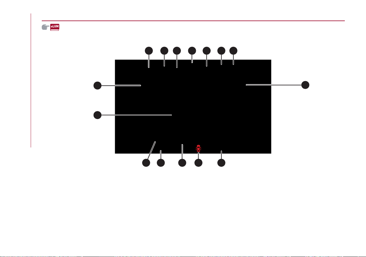
KNOWING THE INSTRUMENT PANEL
50
DISPLAY
INFORMATION ON THE DISPLAY
54 05036S0166EM
1. External lights (low beam/high beam) display 2. Transmission, front and side anti-collision system, and Cruise Control information
3. Speed Limiter display 4. Driving assistance systems (FCW, LDW or LKA, HAS) information display 5. Active Cruise Control (ACC)
or Cruise Control (CC) information display 6. Traffic Sign Recognition (TSR) or Speed Limiter information display 7. Traffic Sign
Recognition (TSR) information display 8. Time 9. External temperature 10. Main display area: car speed display, Trip Computer
information, etc ... 11. Driving mode display (Alfa DNA system) 12. Distance covered in km (or miles) display (milometer) 13. Fuel
consumption graphic bar 14. Warning indications display (e.g. danger of ice, open doors, ABS operation, etc.) 15. Range
1 2 3
4
5 6 7
8
10
9
11 12 13 14 15
51
DISPLAY DESCRIPTION
The vehicle is equipped with a 7" TFT
Display.
When one of the doors is opened/closed,
with the engine turned off, the display is
activated, showing the total mileage for a
few seconds.
During operation, the display is divided
into multiple sections which show driving
data, warnings and failure indications.
Gearbox information
Shows the following information related
to the transmission operation mode (M,
P, R, N, D).
In D mode, when changing gear using the
steering wheel lever (where provided),
or manually M, it also show the gear
engaged with a number.
In M mode, it also shows when to shift
gear up or down.
Front, side anti-collision systems,
Cruise Control
Displays the operation the following
modes:
Forward Collision Warning (FCW)
Lane Departure Warning (LDW)
Lane Keeping Assist (LKA)
Cruise Control (CC) or Active Cruise
Control (ACC) (where provided)
For further information, see relevant
paragraphs.
Speed limit
Shows information regarding the Speed
Limiter function.
For further information, see relevant
paragraph.
Reconfigurable main area
Can display the following screens:
Home
Trip A
Trip B (can be activated/deactivated
on the Connect system)
Performance
Alternative Performance
The screens can be selected, on rotation,
bypressing the buttonshowninfig.55.
55 05036V0002EM
Depending on the chosen driving mode
(Dynamic, Normal, Advanced Efficiency),
which can be selected through the “Alfa
DNA™” system, the screens may be
graphically different. The navigation
instructions and call information can be
repeated on the Connect system display
and also in this area of the display. These
functions can be set on the Connect
system.
Home
The parameters shown on the display,
for the modes: Dynamic, Normal and
Advanced Efficiency are:
Time
External temperature
Current speed (shown only if
the repeat mode of the Phone and
Navigation functions have not been
previously activated).
Range
RACE mode (where provided)
In RACE mode (where provided) the
consumption indication index is not
active and a sports gearshift indicator is
displayed.
The sports gear change indicator is
represented by three yellow segments
fig. 56.
The two white notches which are shown
at the third segment blink to indicate the
need to shift gear.

KNOWING THE INSTRUMENT PANEL
52
56 05036S0177EM
Trip A and B
For all driving modes (“Dynamic”,
“Normal” and “Advanced Efficiency”),
with the ignition device ON, the "Trip
computer" can be used to display the
values related to the car’s operating
state.
This function is characterised by two
separate records, called “Trip A” and
“Trip B” (the latter can be deactivated
by Connect system), where the car’s
“complete missions” (journeys) are
recorded in a reciprocally independent
manner.
“Trip A” and “Trip B” are used to display
the values relating to:
Distance travelled
Average fuel consumption
Average speed
Active trip
Fuel level gauge
To reset the values, press and hold down
the button on the right stalk.
Performance
The displayed parameters vary
depending on the active mode. The
modes can be selected through the “Alfa
DNA™” system and are as follows:
Normal
The screen graphically reproduces
some parameters closely linked to the
efficiency of the driving style, with a view
to limiting consumption.
Advanced Efficiency
The three central icons on the screen
indicate the effectiveness of the driving
style, linked to the following parameters:
acceleration
deceleration
gearshift
with a view to limiting fuel consumption.
The graphic bar below the icons shows
current consumption and the green line
represents the optimal area. The globe
lights up gradually according to lower
consumption.
Dynamic
The displayed parameters are related
to car stability, the graphs illustrate
the trend of the longitudinal/lateral
accelerations (G-meter information),
considering gravity acceleration as a
reference unit.
Lateral acceleration peaks are also
indicated.
Race (where provided)
The displayed parameters are related
to car stability, the graphs illustrate
the trend of the longitudinal/lateral
accelerations (G-meter information),
considering gravity acceleration as a
reference unit.
Lateral and longitudinal acceleration
peaks are also indicated.
Alternative Performance
The displayed parameters vary
depending on the active mode. The
modes can be selected through the “Alfa
DNA™” system and are as follows:
Normal and Advanced Efficiency
The displayfig.57 graphicallyshows the
values of:
instantaneous consumption;
average fuel consumption (based on
"Trip A");
Below a certain speed value, when the
accelerator pedal is not pressed or in the
event of failure, dashes are displayed in
place of the consumption value ("– –. –").
53
57 05036S0173EM
Dynamic
The displayfig.58 graphicallyshows the
values of:
accelerator pedal position (expressed
in percentage);
brake pedal position (expressed in
percentage);
engine coolant temperature (H = hot C
= cold).
Race (where provided)
The displayfig.59 graphicallyshowsthe
values of:
engine torque;
turbocharger pressure;
engine oil pressure (L = low pressure/H
= high pressure).
NOTE The engine torque and
turbocharger pressure values vary
according to the engine type.
Compass
Views the position indicating the cardinal
point.
Odometer
Displays the total kilometres (or miles)
travelled.
Fault indications
Area dedicated to displaying failures, the
following symbols could be displayed on
rotation:
Low criticality symbols (yellow amber).
High criticality symbols (red).
Vehicle range
Displays the kilometres (or miles) left
before the fuel tank is empty.
Exterior lights symbols
Displays the icon related to the active
mode among the following:
dipped beam headlights;
main beam headlights
Auto low beam headlights;
Auto main beam headlights.
PARAMETERS SET BY USER
A series of functions can be set using the
Connect system.
The basic settings only are described:
"Units & Language"
"Clock & Date"
"Cluster"
To access the list with the
aforementioned items, proceed as
follows: from the main menu, activated
by pressingthe MENUbutton(1)fig.60,
select the function "Settings", by turning
and pressing the Rotary Pad (2).
Turn the Rotary Pad to choose the
desired option and press to activate it.
59 05036S0175EM
58 05036S0174EM
water
brakegas
oil
turbo
torque
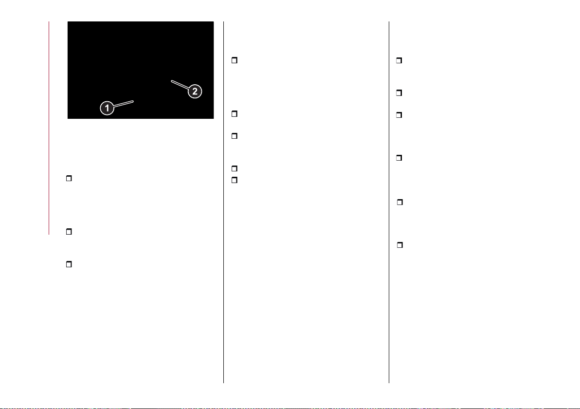
KNOWING THE INSTRUMENT PANEL
54
60 04026V0555EM
Units & Language
The following settings can be modified
when this mode is selected:
“Units” (by selecting this item you can
choose between the metric, imperial or
custom systems; this last option lets you
set the measure unit for each individual
size).
“Language” (by selecting this item
you can choose the system viewing
language).
“Restore Settings” (allows you to
delete the current menu settings and
restore the factory settings).
To access and adjust the various
settings, turn and press the Rotary Pad
to select and confirm the selection.
Clock & Date
The following settings can be modified
when this mode is selected:
“Sync with GPS Time”
(activates/deactivates the clock
synchronization through the GPS; if the
function is deactivated, the options Set
Time and Set Date are enabled).
“Set Time” (allows to manually set the
time).
“Time Format” (allows to choose the
time format between a 12-hour and a 24-
hour clock).
"Set Date” (to set the date manually).
“Restore Settings” (allows you to
delete the current menu settings and
restore the factory settings).
To access and adjust the various
settings, turn and press the Rotary Pad
to select and confirm the selection.
Control panel
The following settings can be modified
when this mode is selected:
"Warning Buzzer Volume" (allows you
to set the volume of the warning buzzer
on seven levels).
"Trip B" (to activate/deactivate the
function).
"Show Phone Info” (allows you to
activate/deactivate repetition of the
phone function screens also on the
instrument panel display).
"Show Audio Info” (allows you to
activate/deactivate repetition of the
audio function screens (Radio and Media)
also on the instrument panel display).
“Show Nav Info” (allows you to
activate/deactivate repetition of the
navigator function screens also on the
instrument panel display).
“Restore Settings” (deletes the current
settings and restores the factory
settings).
To access and adjust the various
settings, turn and press the Rotary Pad
to select and confirm the selection.
55
WARNING LIGHTS AND MESSAGES
WARNING The warning light switches on together with a dedicated message and/or acoustic signal when applicable. These
indications are indicative and precautionary and as such must not be considered as exhaustive and/or alternative to the information
contained in the Owner Handbook, which you are advised to read carefully in all cases. In the event of a failure indication, always refer
to the contents of this chapter.
WARNING The failure indicators appearing on the display are divided into two categories: very serious and less serious failures.
Serious faults are indicated by a repeated and prolonged warning "cycle". Less serious faults are indicated by a warning "cycle" with
a shorter duration. You can stop the warning cycle in both cases by pressing the button located on the windscreen wiper lever. The
instrument panel warning light will stay on until the cause of the failure is eliminated.
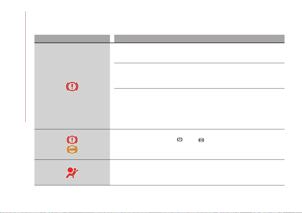
KNOWING THE INSTRUMENT PANEL
56
WARNING LIGHTS ON INSTRUMENT PANEL
Possible detailed messages and/or acoustic signalling can be matched to a few warning lights and symbols.
Red warning lights
Warning light What it means
INSUFFICIENT BRAKE FLUID / ELECTRIC PARKING BRAKE ON
The warning light switches on when the ignition device is brought to ON, but it should switch off after
a few seconds.
Low brake fluid level
The warning light turns on when the level of the brake fluid in the reservoir falls below the minimum
level, possibly due to a leak in the circuit.
Go to an Alfa Romeo Dealership to have the system checked as soon as possible.
Electric parking brake on
The warning light switches on when the electric parking brake is engaged.
Release the electric parking brake, then check that the warning light has switched off.
If the warning light stays on, contact an Alfa Romeo Dealership.
WARNING If the car is parked on a gradient of more than 30% and/or the brake temperature is
greater than 662°F (350°C), when the parking brake is engaged, the warning light will flash to indicate
a potentially unsafe condition.
EBD FAILURE
The simultaneous switching on of the (red) and (amber) warning lights with the engine on
indicates either a failure of the EBD system or that the system is not available. In this case, the rear
wheels may suddenly lock and the vehicle may swerve when braking sharply.
Drive very carefully to the nearest Alfa Romeo Dealership to have the system inspected immediately.
AIR BAG FAILURE
The warning light switches on when the ignition device is brought to ON, but it should switch off after
a few seconds. If the warning light switches on constantly, this indicates a failure in the airbag system.
25) 26)
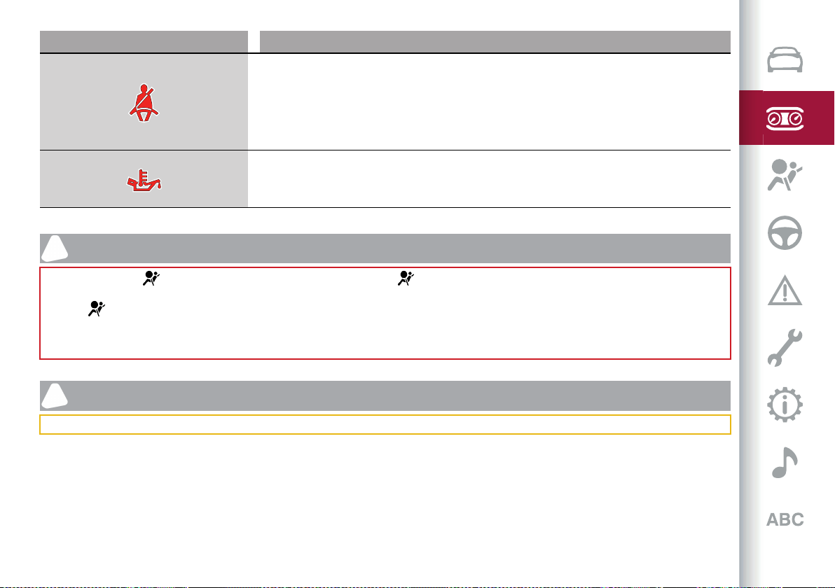
57
Warning light What it means
FRONT SEAT BELTS NOT FASTENED
The warning light switches on constantly if the vehicle is stationary and the driver side or passenger
side seat belt, with the passenger seated, is not fastened. The warning light flashes and an acoustic
warning will sound if the car is in motion and the driver side or passenger side seat belt, with the
passenger seated, is not correctly fastened.
Fasten or check correct fastening of the front occupants' seat belts.
EXCESSIVE ENGINE OIL TEMPERATURE
The warning light switches on in the case of engine oil overheating.
If the problem persists, contact an Alfa Romeo Dealership. 12)
WARNING
25) The failure of the warning light is signalled by the switching on of the icon on the instrument panel. In this case, the warning light may not
indicate any faults with the restraint systems. Before proceeding, contact an Alfa Romeo Dealership to have the system checked immediately.
26) If the warning light does not switch on when the ignition device is moved to ON or if it stays on while driving (together with the message on
the display), there might be a fault in the restraint systems; in this case, the air bags or pretensioners may not deploy in the event of an accident
or, in a lower number of cases, they could deploy erroneously. Before proceeding, contact an Alfa Romeo Dealership to have the system checked
immediately.
IMPORTANT
12) If the symbol switches on while driving, stop the car and the engine immediately.
KNOWING THE INSTRUMENT PANEL
58
Amber warning lights
Warning light What it means
ABS FAILURE
The warning light switches on when the ignition device is brought to ON, but it should switch off after
a few seconds.
The warning light switches on to indicate an ABS fault. In this case the braking system maintains its
efficiency unaltered but without the advantage of the ABS system.
Drive carefully and contact an Alfa Romeo Dealership as soon as possible.
TPMS FAILURE
The warning light switches on when a failure is detected in the TPMS. Should one or more wheels be
fitted without sensors, the display will show a warning message until initial conditions are restored.
Do not continue driving with one or more flat tyres as handling may be compromised.
Stop the vehicle, avoiding sharp braking and steering. Immediately restore the correct inflation
pressure using the Tyre Repair Kit (see "Repairing a wheel" paragraph in the "In an emergency"
chapter) and contact the dedicated Alfa Romeo Dealership as soon as possible.
Low tyre pressure
The warning light switches on to indicate that the tyre pressure is lower than the recommended
value and/or that slow pressure loss is occurring. In these cases, optimal tyre duration and fuel
consumption may not be guaranteed.
In any situation in which the message on the display is "See manual", it is ESSENTIAL to refer to the
contents of the "Wheels and rims" paragraph in the "Technical data" chapter, strictly complying with
the indications that you find there.
ESC SYSTEM
When the ignition device is brought to ON, the warning light switches on, but should switch off as
soon as the engine is started.
ESC system intervention: Intervention by the system is indicated by the flashing of the warning light:
it indicates that the car is in critical stability and grip conditions.
ECS system failure: If the warning light does not switch off, or if it stays on with the engine running, a
failure was found in the ESC system.
In these cases, contact an Alfa Romeo Dealership as soon as possible.
59
Warning light What it means
Hill Start Assist system failure: the switching on of the warning light indicates a Hill Start Assist
system failure.
In these cases, contact an Alfa Romeo Dealership as soon as possible.
PARTIAL/TOTAL DEACTIVATION OF ACTIVE SAFETY SYSTEMS
When the ignition device is brought to ON, the warning light switches on, but should switch off as
soon as the engine is started.
The warning light switches on to indicate that some active safety systems have been partially or
totally deactivated.
For further details about the active safety systems see the "Active safety systems" paragraph in the
"Safety" chapter. When the active safety systems are reactivated, the warning light switches off.
FUEL RESERVE/LIMITED RANGE
The warning light (or the icon on the display) turns on when there are about 1.8 UK gal (8 litres) of fuel
left in the tank, for Diesel versions, and about 2 UK gal (9 litres) of fuel for petrol versions. 27)
EOBD/INJECTION SYSTEM FAILURE
In normal conditions, when the ignition device is brought to ON, the warning light switches on, but it
should switch off as soon as the engine is started.
The operation of the warning light may be checked by the traffic police using specific devices. Comply
with the laws and regulations of the country where you are driving. 13)
Injection system failure
If the warning light remains on, or it switches on whilst driving, the injection system is not working
properly.
The warning light on constantly signals a malfunction in the supply/ignition system which could cause
high exhaust emissions, a possible loss of performance, poor driveability and high consumption.
The warning light switches off if the malfunction disappears, but is still stored by the system.
Under these conditions, the vehicle can continue travelling at moderate speed but without demanding
excessive effort from the engine or high speed.
Prolonged use of the car with the warning light on constantly may cause damage. Contact an Alfa
Romeo Dealership as soon as possible.
KNOWING THE INSTRUMENT PANEL
60
Warning light What it means
Catalytic converter damaged
If the warning light flashes, it means that the catalytic converter may be damaged.
Release the accelerator pedal to lower the speed of the engine until the warning light stops flashing.
Continue the journey at moderate speed, trying to avoid driving conditions that may cause further
flashing and contact an Alfa Romeo Dealership as soon as possible.
AdBlue
®
(UREA) INJECTION SYSTEM FAILURE (2.2 JTD versions only)
The warning light appears, on some versions together with a dedicated message on the instrument
panel display, if a fluid not conforming with nominal features is introduced or if an average AdBlue
®
(UREA) consumption of over 50% is detected.
Contact an Alfa Romeo Dealership as soon as possible.
If the problem is not solved, a specific message will appear on the instrument panel display whenever
a certain threshold is reached until it will no longer be possible to start the engine. When there are
approximately 124 miles (200 km) before you will no longer able to restart the engine, on some
versions a dedicated message will appear fixed on the instrument panel display accompanied by
warning tone.
CATALYTIC CONVERTER DAMAGED (2.0 T4 MAir versions with GPF only)
If the warning light flashes, it means that the catalytic converter may be damaged.
Release the accelerator pedal to lower the speed of the engine until the warning light stops flashing.
Continue the journey at moderate speed, trying to avoid driving conditions that may cause further
flashing and contact an Alfa Romeo Dealership as soon as possible.
FORWARD COLLISION WARNING SYSTEM (FCW) (where available)
This warning light informs the driver that the frontal collision alarm function is not enabled.
REAR FOG LIGHT
The warning light switches on when the rear fog light is activated.
61
WARNING
27) If the warning light (or the icon on the display) flashes while driving, contact an Alfa Romeo Dealership.
IMPORTANT
13) If, turning the ignition device to ON, the warning light does not turn on or if it turns on steadily or flashing while driving (on some versions
together with the message on the display), contact an Alfa Romeo Dealership as soon as possible.
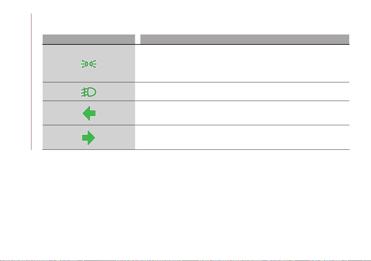
KNOWING THE INSTRUMENT PANEL
62
Green warning lights
Warning light What it means
SIDE LIGHTS AND DIPPED BEAM HEADLIGHTS
The warning light switches on when the side lights or dipped headlights are turned on.
"Follow me" function engaged
This function allows the headlights to remain on for 30, 60 or 90 seconds after the ignition device
was placed in STOP position.
FOG LIGHTS
The warning light comes on when the front fog lights are turned on.
LEFT DIRECTION INDICATOR
The warning light switches on when the direction indicator control stalk is moved downwards or,
together with the right direction indicator, when the hazard warning light button is pressed.
RIGHT DIRECTION INDICATOR
The warning light switches on when the direction indicator control stalk is moved upwards or,
together with the left direction indicator, when the hazard warning light button is pressed.

63
SYMBOLS ON THE DISPLAY
Red symbols
Symbol What it means
LOW ENGINE OIL PRESSURE
The symbol indicates that the engine oil pressure is low.
If it turns on temporarily or flashes (for about 5 seconds), check the oil level by following the
corresponding procedure (see the description in the “Checking levels” paragraph in the “Maintenance
and care” chapter) and top up to the correct level if necessary.
If the symbol turns on continuously, contact an Alfa Romeo Dealership to have the system checked.
WARNING IF THE SYMBOL TURNS ON CONTINUOUSLY: Do not use the car until the failure has
been solved.
When the symbol turns on, it does not indicate the amount of oil in the engine: the oil level can be
checked on the display upon entering the vehicle and also by activating the "Oil level" function on the
Connect system. 14)
ALTERNATOR FAILURE
The switching on of the symbol with engine on corresponds to an alternator failure.
Contact an Alfa Romeo Dealership as soon as possible.
POWER STEERING FAILURE
If the symbol remains on, you could not have steering assistance and the effort required to operate
the steering wheel could be increased; steering is, however, possible.
Contact an Alfa Romeo Dealership as soon as possible.
ALFA™ SYSTEM STEERING TORQUE (AST) FAILURE
The switching on of the symbol signals a failure in the automatic steering correction system.
Contact an Alfa Romeo Dealership to have the system checked.

KNOWING THE INSTRUMENT PANEL
64
Symbol What it means
ENGINE COOLANT TEMPERATURE TOO HIGH
The symbol lights up when the engine has overheated.
In normal driving conditions: stop the car, switch off the engine and check that the coolant level in
the reservoir is not below the MIN mark. In this case, wait for the engine to cool down, then slowly
and carefully open the cap, top up with coolant and check that the level is between the MIN and
MAX marks on the reservoir itself. Also check visually for any fluid leaks. Contact an Alfa Romeo
Dealership if the symbol comes on when the engine is started again.
If the car is used under demanding conditions (e.g. in high-performance driving): slow down and, if
the warning light stays on, stop the car. Wait for 2 or 3 minutes with the engine running and slightly
accelerated to further favour the coolant circulation. Then stop the engine. Check that the coolant
level is correct as described above
IMPORTANT Over demanding routes, it is advisable to keep the engine running and slightly
accelerated for a few minutes before turning it off.
DOORS OPEN
The symbol switches on when one or more doors are not completely shut. An acoustic signal is
activated with the doors open and the car moving.
Close the doors properly.
BONNET NOT PROPERLY SHUT
The symbol turns on when the bonnet is not properly closed, along with the icon, an image of the car
with an open bonnet also appears on the display.
an acoustic warning is heard when the bonnet is open and the car is moving.
Close the bonnet properly.
TAILGATE NOT PROPERLY SHUT
The symbol turns on when the tailgate is not properly closed, along with the icon, an image of the
vehicle with an open tailgate also appears on the display.
A buzzer is heard with open tailgate and vehicle moving.
Close the tailgate properly.
AUTOMATIC TRANSMISSION FAILURE
The symbol lights up, together with an acoustic warning, to indicate that the automatic transmission
is faulty. Contact an Alfa Romeo Dealership as soon as possible. 15)
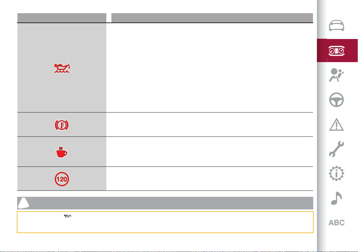
65
Symbol What it means
INSUFFICIENT ENGINE OIL LEVEL
The symbol lights up, along with the related message on the display, to indicate low engine oil level.
Top up the oil as soon as possible in order to restore the correct level in the sump (see "Engine
compartment - Checking the levels" paragraph in the "Maintenance and care" chapter for information
on the quantity to be top up).
You may carry out this operation on your own, using a suitable type of oil, as prescribed by Alfa
Romeo (see the "Fluids and lubricants" paragraph in the "Technical specifications" chapter for
detailed information).
Quadrifoglio version: the level must also be checked using the dipstick below the boot (see chapter
"Servicing and care").
OIL OVER MAXIMUM LEVEL
The symbol switches on, along with the respective message on the display, to indicate that the engine
oil level is too high. Go to an Alfa Romeo dealership as soon as possible to have the correct level
restored. Run the engine under 3000 rpm during this time.
BRAKE DISC TEMPERATURE
When the symbol turns on, it indicates an excessive temperature of the brake discs.
Let the braking system cool down by reducing the speed.
DAA SYSTEM ACTIVATION
The symbol appears, together with a message on the display, in case of activation of the DAA (Drive
Attention Assist) system.
Stop to pause while driving, pulling the car over in safe conditions.
SPEED LIMIT EXCEEDED
(only SASO version)
The symbol switches on when the speed limit of 74.5 mph (120 km/h) is exceeded.
IMPORTANT
14) If the warning light switches on when driving, stop the engine immediately and contact an Alfa Romeo Dealership.
15) Driving the vehicle with this symbol on may severely damage the transmission, with resulting breakage. The oil may also overheat: contact with
hot engine or with exhaust components at high temperature could cause fires.
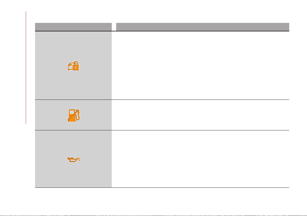
KNOWING THE INSTRUMENT PANEL
66
Amber symbols
Symbol What it means
ENGINE IMMOBILIZER FAILURE / BREAK-IN ATTEMPT
Engine Immobilizer system failure
The symbol appears to report a failure of the Engine Immobilizer system. Contact an Alfa Romeo
Dealership as soon as possible.
Break-in attempt
The symbol switches on when the ignition device is moved to ON position, to indicate a possible
break-in attempt detected by the alarm system.
Electronic key not recognised
The symbol switches on when the engine is started and the electronic key is not recognized by the
system.
Alarm system failure
This symbol switches on to report an alarm system failure.
FUEL CUT-OFF SYSTEM OPERATION
The symbol switches on in the event of fuel cut-off system intervention.
For reactivating the fuel cut-off system, refer to the description in the "Fuel cut-off system" section
in the "In an emergency" chapter. If it is not possible to restore the fuel supply, contact an Alfa Romeo
Dealership.
DECAYED ENGINE OIL
(where provided)
The symbol is displayed only for a limited time.
IMPORTANT After the first indication, each time the engine is started the symbol will continue to
switch on as described above until the oil is changed.
If the symbol flashes, this does not mean that there is a fault on the vehicle, rather it simply reports
that it is now necessary to change the oil as a result of regular use of the vehicle. The deterioration
of engine oil is accelerated by using the vehicle for short drives, preventing the engine from reaching
operating temperature.
Contact an Alfa Romeo Dealership as soon as possible. 16)
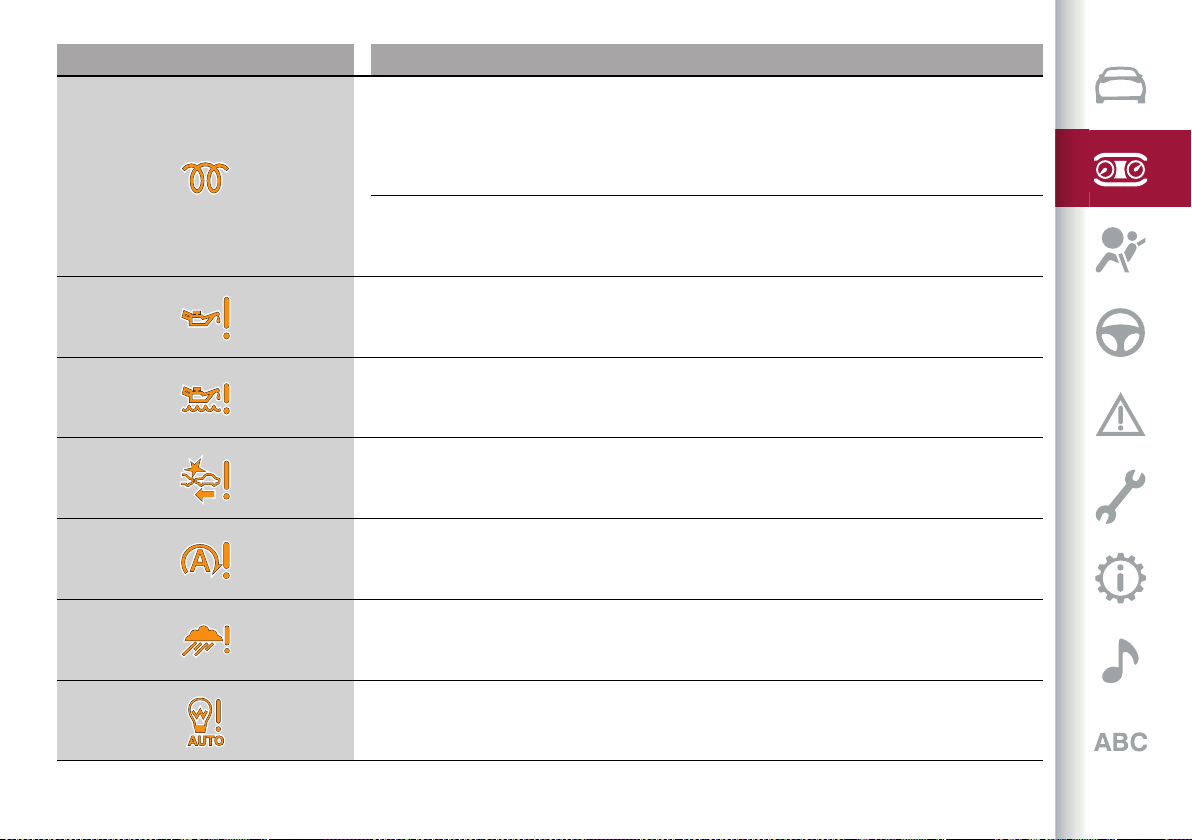
67
Symbol What it means
GLOW PLUG PREHEATING (Diesel versions)
This warning light comes on when the ignition device is brought to ON and will switch off when the
glow plugs have reached the preset temperature. The engine can be started as soon as the symbol
turns off.
IMPORTANT In mild or high temperature conditions, the symbol turns on for a very short time only.
GLOW PLUG PREHEATING FAILURE (Diesel versions)
If the symbol flashes, it indicates a fault in the glow plug preheating system.
In this case, contact the Alfa Romeo Service Network as soon as possible.
ENGINE OIL PRESSURE SENSOR FAILURE
The symbol switches on in the event of engine oil level sensor failure.
Contact an Alfa Romeo Dealership as soon as possible.
ENGINE OIL LEVEL SENSOR FAILURE
The symbol switches on in the event of engine oil level sensor failure.
Contact an Alfa Romeo Dealership as soon as possible.
FORWARD COLLISION WARNING (FCW) SYSTEM FAILURE
The symbol appears in the event of failure of the Forward Collision Warning system.
Contact an Alfa Romeo Dealership as soon as possible.
START&STOP EVO SYSTEM FAILURE
The symbol appears to indicate a Start&Stop Evo system failure.
Contact an Alfa Romeo Dealership as soon as possible to have the failure eliminated.
RAIN SENSOR FAILURE
The symbol switches on in the case of failure of the automatic windscreen wiper.
Contact an Alfa Romeo Dealership as soon as possible.
DUSK SENSOR FAILURE
The symbol switches on in the case of failure of the automatic low beam alignment.
Contact an Alfa Romeo Dealership as soon as possible.
KNOWING THE INSTRUMENT PANEL
68
Symbol What it means
BLIND SPOT MONITORING SYSTEM FAILURE
The symbol comes on in the event of a Blind Spot Monitoring system failure.
Contact an Alfa Romeo Dealership as soon as possible.
FUEL LEVEL SENSOR FAILURE
The symbol switches on in the event of fuel level sensor failure
Contact an Alfa Romeo Dealership as soon as possible.
EXTERIOR LIGHTS FAILURE
The symbol switches on to indicate a failure on the following lights: daytime running lights (DRLs)
/ parking lights / trailer direction indicators (if present) / trailer lights (if present) / side lights /
direction indicators / rear fog light / reversing light / brake lights / number plate lights.
The failure may be caused by a blown bulb, a blown protection fuse or an interruption of the electrical
connection.
Replace the bulb or the relevant fuse. Contact an Alfa Romeo Dealership.
KEYLESS START SYSTEM FAILURE
The symbol switches on in the event of Keyless Start system failure.
Contact an Alfa Romeo Dealership as soon as possible.
FUEL CUT-OFF SYSTEM FAILURE
The symbol switches on in the event of fuel cut-off system failure.
Contact an Alfa Romeo Dealership as soon as possible.
LANE DEPARTURE WARNING SYSTEM (LDW) FAILURE
The symbol comes on also in the case of a fault to the Lane Departure Warning system.
Contact an Alfa Romeo Dealership as soon as possible.
LANE KEEPING ASSIST (LKA) SYSTEM FAILURE
The symbol comes on in the event of a failure in the Lane Keeping Assist system.
Contact an Alfa Romeo Dealership as soon as possible.
69
Symbol What it means
AUTOMATIC HIGH BEAM HEADLIGHTS FAILURE
(where provided)
The symbol switches on to report a failure of the automatic main beam headlights.
Contact an Alfa Romeo Dealership as soon as possible to have the failure eliminated.
WATER IN DIESEL FILTER (Diesel versions)
The symbol switches on constantly while driving, along to indicate the presence of water in the diesel
filter. 17)
DPF CLEANING (particulate trap) in progress (diesel versions with DPF only)
The symbol comes on when the starter switch is brought to ON, but it should switch off after a few
seconds.
The symbol switches on constantly to indicate that the DPF system needs to eliminate the trapped
pollutants (particulate) through the regeneration process.
The symbol does not switch on during every DPF regeneration, but only when driving conditions
require that the driver is notified.
To turn off the symbol, keep the vehicle in motion until the regeneration process is over. The process
normally takes about 15 minutes. Optimal conditions for completing the process are achieved by
travelling at 37 mph (60 km/h) with engine speed above 2000 rpm.
When this symbol switches on, it does not indicate a fault and thus it should not be taken to a
workshop.
KNOWING THE INSTRUMENT PANEL
70
Symbol What it means
GPF (Gasoline Particulate Filter) CLEANING in progress (2.0 T4 MAir versions only)
The symbol switches on fixed, together with a dedicated message on the display, to indicate that the
GPF system needs to eliminate the trapped pollutants (particulate) by means of the regeneration
process.
The symbol does not light up on during every GPF regeneration, but only when driving conditions
require that the driver is notified.
To turn off the symbol, keep the vehicle in motion until the regeneration process is over. The optimal
conditions for completing the process are achieved by varying the speed of the car (pressure on the
accelerator pedal).
Hold a speed faster than 45 mph (70 km/h) on extra-urban roads, varying the pressure on the
accelerator pedal and sometimes releasing it completely, until the symbol and message disappear
from the display.
When this symbol switches on, it does not indicate an anomaly and thus it should not be taken to a
workshop.
GPF (Gasoline Particulate Filter) FAILURE (2.0 T4 MAir versions only)
The symbol lights up fixed together with the warning light and dedicated messages appear on the
display in case of failure to the GPF (Gasoline Particulate Filter).
Contact an Alfa Romeo Dealership as soon as possible to have the failure eliminated.
AUTOMATIC TRANSMISSION FLUID OVERHEATING
The symbol switches on in the case of transmission overheating, after a particularly demanding use.
In this case an engine performance limitation is carried out.
With engine off or at idle speed, wait until the symbol switches off.
TRAILER LIGHT CONTROL UNIT FAILURE
The symbol turns on to warn of failure in the control unit that manages the trailer lights.
Check that the trailer light is correctly connected to the socket. If the fault persists the next time you
start the engine, contact the Alfa Romeo Dealership as soon as possible to have the system checked.
AUDIO SYSTEM FAILURE
The symbol switches on to report a failure of the audio system.
Contact an Alfa Romeo Dealership as soon as possible to have the failure eliminated.

71
Symbol What it means
ABS ACTIVATION
The symbol appears when the ABS cuts in.
SPEED LIMITER SYSTEM FAILURE
While driving, the symbol switches on to signal a Speed Limiter system anomaly.
Contact an Alfa Romeo Dealership as soon as possible to have the failure eliminated.
INSUFFICIENT ENGINE COOLANT LEVEL
If the symbol switches on, it indicates a low engine coolant level condition.
Top up as described in the "Maintenance and Care" chapter.
FUEL TANK CAP
Lights up if the fuel tank cap is open or not properly closed.
Tighten the cap properly.
ELECTRIC PARKING BRAKE FAILURE
The symbol and the respective message appear on the display to indicate a failure in the electric
parking brake system.
This failure could partially or completely block the car because the electric parking brake could
remain activated even if automatically or manually disengaged using the relevant controls.
If the car can still be used (electric parking brake not engaged), drive carefully to the nearest Alfa
Romeo dealership, remembering that the electric parking brake will not work. 28)
GENERIC INDICATION
Signals information and failures. The accompanying messages describe the failure.
FOUR WHEEL DRIVE FAILURE
This symbol switches on to report a four-wheel drive system failure.
Contact an Alfa Romeo Dealership as soon as possible to have the failure eliminated.
KNOWING THE INSTRUMENT PANEL
72
Symbol What it means
TEMPORARY FOUR-WHEEL DRIVE FAILURE (where provided)
The symbol will appear to indicate that the AWD dynamic control system is temporarily deactivated
to prevent damage because of high engine load. The traction system will work in RWD mode in this
case.
Until the symbol appears on the display, reduce the load to allow the system to cool down. The AWD
system will resume normal operation when the symbol disappears from the display.
DYNAMIC DRIVE CONTROL SYSTEM FAILURE
The symbol appears to indicate the dynamic traction control system failure.
AFS SYSTEM FAILURE
The symbol appears to indicate the automatic directional light system failure.
Go to an Alfa Romeo Dealership to have the system checked.
SOFT SUSPENSION CALIBRATION INSERTION (where provided)
The system appears when the most comfortable suspension setting is activated.
SHOCK ABSORBER FAILURE (ADC) (where provided)
While driving, if the symbol switches on, it signals a failure in the suspension system.
Contact an Alfa Romeo Dealership to have the system checked.
TAILGATE ELECTRIC OPENING/CLOSING FAILURE
The symbol turns on to indicate a tailgate electric opening/closing system failure.
Contact an Alfa Romeo Dealership as soon as possible to have the failure eliminated.
ELECTRIC TOW HOOK FAILURE
The symbol turns on to indicate an electric towing hook extraction/closing system failure.
Contact an Alfa Romeo Dealership as soon as possible to have the failure eliminated.
73
Symbol What it means
WINDSCREEN WASHER LIQUID LEVEL
The symbol appears for some seconds to indicate that the level of the windscreen and headlight
washing fluid (if any) is low.
Refill the liquid: to do this, see the "Level check" paragraph in the "Maintenance and care" chapter.
Always use liquid with the features indicated in the "Liquids and lubricants" section in the "Technical
information" chapter.
LOW AdBlue
®
(UREA) DIESEL EMISSIONS ADDITIVE LEVEL WARNING (2.2 JTD versions only)
The AdBlue
®
Diesel Emissions Additive (UREA) low level symbol turns on when the Diesel
Emissions Additive (UREA) level is low. A warning and a message indicating the need to top up
AdBlue
®
(UREA) also appear on the display with a dedicate message.
The symbol stays on until the tank is topped up with at least 1.11 UK gal (5 litres of AdBlue
®
(UREA)).
If you do not top up, a specific message will appear on the instrument panel display whenever a
certain threshold is reached until it will no longer be possible to start the engine.
A message will appear permanently on the instrument panel and an acoustic tone will be heard when
there is about 125 miles (200 km) of range left.
A specific message will appear on the instrument panel display when there are 0 miles (0 km) of range
left. It will no longer be possible to restart the engine after it has been stopped. It will be possible to
restart the engine after pouring at least 1.11 UK gal (5 litres of AdBlue
®
(UREA) in the tank). Top up the
AdBlue
®
(UREA) tank as soon as possible with at least 1.11 UK gal (5 litres) of AdBlue
®
(UREA).
If you top up with remaining range of AdBlue® (UREA) in the tank equal to 0 miles (0 km), you may
need to wait 2 minutes before starting the engine.
18)
ACTIVE CRUISE CONTROL SYSTEM FAILURE
The symbol appears while driving to indicate a failure in the Adaptive Cruise Control system.
Contact an Alfa Romeo Dealership to have the system checked.
WEAR ON BRAKE PADS
The symbol lights up when the brake pads have reached their wear limit. Contact an Alfa Romeo
Dealership as soon as possible.
IMPORTANT Always use genuine parts or equivalents because the Integrated Brake System (IBS)
system could detect anomalies.
KNOWING THE INSTRUMENT PANEL
74
Symbol What it means
PARK SENSORS SYSTEM FAILURE
The symbol appears when the system is faulty or not available.
Contact an Alfa Romeo Dealership to have the system checked.
POSSIBLE ICE ON ROAD
The symbol turns on when the outside temperature is below or equal to 37.4°F (3°C).
The symbol turns off when the outside temperature is equal to 74.8°F (6°C).
WINDSCREEN WIPER FAILURE
The symbol appears when a windscreen wiper failure is present. Contact an Alfa Romeo Dealership.
DAA SYSTEM FAILURE
The symbol comes on in the event of a DAA (Driver Attention Assist) system failure.
Contact an Alfa Romeo Dealership as soon as possible to have the failure eliminated.
HAS SYSTEM/TJA SYSTEM FAILURE
The symbol lights up in case of HAS (Highway Assist) or TJA (Traffic Jam Assist) system failure.
Contact an Alfa Romeo Dealership as soon as possible to have the failure eliminated.
75
WARNING
28) If a failure is present with sharp braking,
the rear wheels may lock and the vehicle
may swerve.
IMPORTANT
16) Deteriorated engine oil should be
replaced as soon as possible after the
symbol is switched on, and never more than
500 km after it first switches on. Failure
to observe the above may result in severe
damage to the engine and invalidate the
warranty. When this symbol comes on, it
does not mean that the level of engine oil is
low, so if it flashes you do not need to top up
the engine oil.
17) The presence of water in the fuel system
circuit may cause severe damage to the
injection system and irregular engine
operation. If the symbol is displayed
contact an Alfa Romeo Dealership as soon
as possible to bleed the system. If the
above indications come on immediately
after refuelling, water has probably been
introduced into the tank: stop the engine
immediately and contact an Alfa Romeo
Dealership.
18) When the AdBlue
®
(UREA) tank is empty
and the engine stops it is no longer possible
to restart it until the AdBlue
®
(UREA)
tank is topped up with at least 5 litres of
AdBlue
®
(UREA).
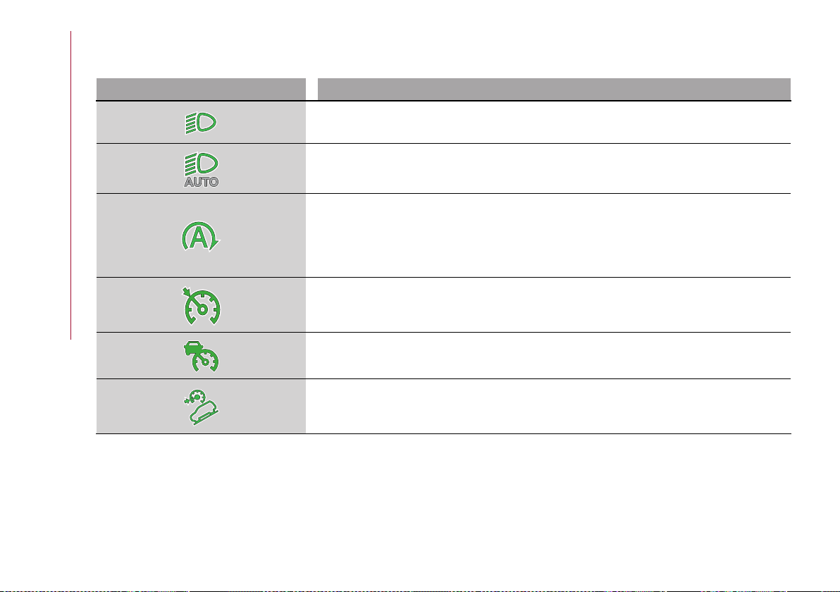
KNOWING THE INSTRUMENT PANEL
76
Green symbols
Symbol What it means
DIPPED BEAM HEADLIGHTS
The symbol comes on when the dipped beam headlights are activated.
AUTOMATIC DIPPED BEAM HEADLIGHTS
The symbol lights up when the automatic dipped beam headlights are on.
START&STOP EVO INTERVENTION
The warning light comes on in the event of Start&Stop Evo system intervention (stopping the
engine).
When the engine is restarted the warning light switches off (for the engine restarting modes see the
"Start&Stop Evo" paragraph in the "Starting and driving" chapter).
CRUISE CONTROL SYSTEM
The symbol comes on when the Cruise Control system is activated.
ACTIVE CRUISE CONTROL SYSTEM
The symbol comes on when the Active Cruise Control system is activated.
HILL DESCENT CONTROL (HDC SYSTEM)
The symbol lights up when the HDC system intervenes.

77
Blue symbols
Symbol What it means
AUTOMATIC MAIN BEAM HEADLIGHTS
The symbol comes on when the automatic main beam headlights are activated.
MAIN BEAM HEADLIGHTS
The symbol comes on when the main beam headlights are activated.
KNOWING THE INSTRUMENT PANEL
78
Messages on the display
Message in the display
AWD temporarily unavailable
The message appears on the display when the AWD dynamic control system is temporarily
deactivated to prevent damage due to high powertrain load. The traction system will work in RWD
mode in this case.
While the message is on the display, reduce the load to allow the system to cool down. The AWD
system will resume normal operation when the message disappears from the display.

The chapter that you are about to read is very important: it
describes the safety systems with which the vehicle is
equipped and provides instructions on how to use them
correctly.
SAFETY
ACTIVESAFETYSYSTEMS .............................................80
DRIVINGASSISTANCESYSTEMS......................................84
DAA(DriverAttentionAssist)SYSTEM ................................95
OCCUPANTPROTECTIONSYSTEMS .................................. 97
SEATBELTS ............................................................... 97
SBA(SeatBeltAlert)SYSTEM ..........................................98
PRE-TENSIONERS .......................................................100
CHILDRESTRAINTSYSTEMS .........................................101
SUPPLEMENTARYRESTRAINTSYSTEM(SRS)-AIRBAG ..........115

SAFETY
80
ACTIVE SAFETY SYSTEMS
The vehicle may be equipped with the
following active safety devices:
ABS (Anti-Lock Brakes);
DTC (Drive Train Control);
ESC (Electronic Stability Control);
TC (Traction Control);
PBA (Panic Brake Assist);
HSA (Hill Start Assist);
AST (Alfa™ Steering Torque);
ATV (Alfa™ Active Torque Vectoring);
HDC (Hill Discent Control).
For the operation of the systems, see the
following pages.
ABS
(Anti-lock Braking System)
This system, which is an integral part
of the braking system, prevents one
or more wheels from locking and
slipping in all road surface conditions,
irrespective of the intensity of the
braking action, ensuring that the vehicle
can be controlled even during emergency
braking and optimising stopping
distances.
The system intervenes during braking
when the wheels are about to lock,
typically in emergency braking or
low-grip conditions, when locking may be
more frequent.
The system also improves control and
stability of the car when braking on a
surface where the grip of the left and
right wheels varies, or on corners.
The Electronic Braking Force
Distribution (EBD) system completes the
system allowing the brake force to be
distributed between the front and rear
wheels.
System intervention
The ABS equipped on this vehicle is
provided with the "Brake by wire"
(Integrated Brake System - IBS) function.
With this system, the brake pedal
command given by pressing the brake
pedal is not transmitted hydraulically
but electronically, therefore, the light
pulsation that could be felt on the pedal
with the traditional system is no longer
perceptible.
29) 30) 31) 32) 33) 34)
DTC (Drive Train Control) SYSTEM
(where provided)
Some versions of this vehicle are
equipped with a four-wheel drive system
(AWD), activated on request, which
offers an optimal drive for countless
driving conditions and road surfaces.
The system reduces the slipping of
the tyres to a minimum, automatically
redistributing the torque to the front and
rear wheels, as needed.
To maximize fuel savings, the car with
AWD automatically passes to rear-
wheel drive (RWD) when the road and
environmental conditions are such that
they would not cause the tyres to slip.
When the road and environmental
conditions require better traction, the
vehicle automatically goes to AWD
mode.
35)
WARNING If the system failure symbol
switches on, after starting the engine
or while driving, it means that the
AWD system is not working properly.
If the warning message activates
frequently, it is recommended to carry
out maintenance operations.
36)
ESC SYSTEM
(Electronic Stability Control)
The ESC system improves the directional
control and stability of the car in various
driving conditions.
The ESC system corrects the car’s
understeer and oversteer, distributing
the brake force on the appropriate
wheels. The torque supplied by the
engine can also be reduced in order to
maintain control of the vehicle.
The ESC system uses sensors installed
on the car to determine the trajectory
that the driver intends to follow and
compares it with the car’s effective
trajectory. When the real trajectory
deviates from the desired trajectory, the

81
ESC system intervenes to counter the
vehicle’s understeer or oversteer.
Oversteer: occurs when the car is
turning more than it should according to
the angle of the steering wheel.
Understeer: occurs when the vehicle
is turning less than it should according to
the angle of the steering wheel.
System intervention
The intervention of the system is
indicated by the flashing of the ESC
warning light on the instrument panel, to
inform the driver that the car stability
and grip are critical.
37) 38) 39) 40) 41)
System deactivation
The ESC system deactivates
automatically when using RACE driving
mode (where provided).
TC (Traction Control) SYSTEM
The system automatically operates in
the event of slipping, loss of grip on wet
roads (aquaplaning) and acceleration on
slippery, snowy or icy roads, etc. on one
or both drive wheels. Depending on the
slipping conditions, two different control
systems are activated:
if the slipping involves both drive
wheels, the system intervenes, reducing
the power transmitted by the engine;
if the slipping only involves one of the
drive wheels, the BLD (Brake Limited
Differential) function is activated,
automatically braking the wheel which is
slipping (the behaviour of a self-locking
differential is simulated). This will
increase the engine torque transferred
to the wheel which isn't slipping.
System intervention
The intervention of the system is
indicated by the flashing of the ESC
warning light on the instrument panel, to
inform the driver that the car stability
and grip are critical.
42) 43) 44) 45) 46)
PBA (Panic Brake Assist) SYSTEM
The PBA system is designed to improve
the vehicle’s braking capacity during
emergency braking.
The system detects emergency braking
by monitoring the speed and force with
which the brake pedal is pressed, and
consequently applies the optimal brake
pressure. This can reduce the braking
distance: the PBA system therefore
complements the ABS.
Maximum assistance from the PBA
system is obtained by pressing the brake
pedal very quickly. In addition, the brake
pedal should be pressed continuously
during braking, avoiding intermittent
presses, to get the most out of the
system. Do not reduce pressure on the
brake pedal until braking is no longer
necessary.
The PBA system is deactivated when the
brake pedal is released.
47) 48) 49)
HSA (Hill Start Assist) SYSTEM
This is an integral part of the ESC system
and facilitates starting on slopes,
activating automatically in the following
cases:
uphill: vehicle stationary on a road
with a gradient higher than 5%, engine
running, brake pressed and transmission
in neutral or gear other than reverse
engaged;
downhill: vehicle stationary on a road
with a gradient higher than 5%, engine
running, brake pressed and reverse gear
engaged.
When setting off, the ESC system
control unit maintains the braking
pressure on the wheels until the engine
torque necessary for starting is reached,
or in any case for a maximum of 2
seconds, allowing your right foot to be
moved easily from the brake pedal to the
accelerator.
When the 2 seconds have elapsed,
without starting, the system is
automatically deactivated, gradually
releasing the braking pressure.
During this release stage, the typical
mechanical brake release noise can be
SAFETY
82
heard, indicating that the car is about to
move.
50) 51)
AST (Alfa™ Steering Torque) SYSTEM
52)
The AST function integrates the ESC
system with the electric power steering
to increase the safety level of the whole
vehicle.
In critical situations (braking on surfaces
with different grip conditions), through
the AST function, the ESC system
controls the steering to implement an
additional torque contribution on the
steering wheel, to suggest the most
correct manoeuvre to the driver.
The coordinated action of the brakes
and steering increases the sensation of
safety and control of the car.
ATV (Alfa™ Active Torque Vectoring)
SYSTEM
(where provided)
The dynamic drive control is used to
optimise and balance the drive torque
between the wheels of the same axis.
The ATV system improves grip when
cornering by sending more drive torque
to the outside wheel.
Given that, in a turn, the external wheels
of the car travel more than the internal
ones and therefore turn faster, sending a
higher thrust to the external rear wheel
allows for the car to be more stable
and to not suffer a phenomenon called
"understeer". Understeer occurs when,
during a turn, a car tends to widen the set
trajectory, in this situation the lateral
acceleration the car is subjected to
becomes higher that the grip of the tyres,
which are unable to maintain the car in
the trajectory set by the driver through
the steering angle determined by turning
the steering wheel.
HDC (Hill Descent Control) SYSTEM
(where provided)
On cars equipped in this way, this
function is an integral part of the ESC
system and is aimed at keeping the car
at a constant speed during a descent,
operating autonomously and in different
ways on the brakes.
In this way the vehicle stability and
completely safe driving are guaranteed,
above all in poor grip conditions and
steep descents.
The system has three different modes:
Off: the system is deactivated;
Enabled: the system is enabled and
ready to intervene when the activation
conditions are met;
Active: the system actively controls
the car speed.
Enabling the system
To enable the system, press the button
fig. 61.
61 07146V0021EM
The system is enabled if the car speed
is below 20 mph (30 km/h). The system
stays enabled until the car speed reaches
37 mph (60 km/h): the system is disabled
at faster speed.
System activation is indicated by the
white icononthedisplayfig. 62
turning on fixed.
62 05036S0184EM
83
Activation of the system
Once enabled, the HDC system will
activate automatically if the car is driven
downhill on a steep slope, higher than
8%.
The speed set for the HDC system can
beadjustedusingtheSET stalkfig.63 (in
the range from 1.25 mph to 20 mph (from
2 km/h to 30 km/h).
Once the desired speed has been
reached, release the SET stalk and the
HDC system will maintain the set speed.
It is also possible to reduce the set speed
with the brake pedal. The system will
acquire the current speed when the pedal
is released as the reference.
63 07146V0022EM
If the car speed exceeds 6 mph (10 km/h),
but remains below 37 mph (60 km/h) and
the accelerator pedal is released, as soon
as the car gets close to the set speed, the
HDC system will brake to bring the car to
the set speed.
The driver can cancel HDC system
intervention at any time by pressing the
accelerator pedal.
System deactivation
The HDC system is deactivated, but
remains available, if one of the following
conditions is met:
the car is on a descent with insufficient
gradient, below 8%, or a level surface, or
is going uphill;
P (Park) mode is engaged.
Disabling the system
53)
The system is disabled if one of the
following conditions is met:
button pressed;
Cruise Control / Active Cruise Control
is activated.
37 mph (60 km/h) is exceeded.
System deactivation is shown by the icon
on the display turning off.
WARNING
29) For maximum efficiency of the braking
system, a bedding-in period of about 500 km
(310 miles) is required: during this period it
is advisable to avoid sharp, repeated and
prolonged braking.
30) If the ABS intervenes, this indicates that
the grip of the tyres on the road is nearing
its limit: you must slow down to a speed
compatible with the available grip.
31) The ABS cannot overrule the natural
laws of physics, and cannot increase the grip
available according to the condition of the
road.
32) The ABS cannot prevent accidents,
including those due to excessive speed on
corners, driving on low-grip surfaces or
aquaplaning.
33) The capability of the ABS must never
be tested irresponsibly and dangerously,
in such a way as to compromise personal
safety and the safety of others.
34) For the correct operation of the ABS,
the tyres must of necessity be the same
make and type on all wheels, in perfect
condition and, above all, of the prescribed
type and dimensions.
35) There may be a brief delay in shifting to
AWD mode after a tyre slipping event.
36) When a DTC system failure symbol
appears, the driver must be aware of the
different driving reaction and therefore
reduce the speed The symbol warns the
driver not to drive in areas that require four-
wheel drive or on snow-covered roads.
37) The ESC system cannot alter the natural
laws of physics, and cannot increase grip,
which depends on the condition of the road.
38) The ESC system cannot prevent
accidents, including those due to excessive
speed on corners, driving on low-grip
surfaces or aquaplaning.
39) The capability of the ESC system
must never be tested irresponsibly
and dangerously, in such a way as to
compromise personal safety and the safety
of others.
SAFETY
84
40) For the correct operation of the ESC
system, the tyres must necessarily be of the
same make and type on all wheels, in perfect
condition and, above all, of the prescribed
type and size.
41) ESC performance features must not
induce the driver to take unnecessary or
unwarranted risks. Your driving style must
always be suited to the road conditions,
visibility and traffic. The driver is, in any
case, responsible for safe driving.
42) For the correct operation of the TC
system, the tyres must of necessity be the
same make and type on all wheels, in perfect
condition and, above all, of the prescribed
type and dimensions.
43) TC performance features must not
induce the driver to take unnecessary or
unwarranted risks. Your driving style must
always be suited to the road conditions,
visibility and traffic. The driver is, in any
case, responsible for safe driving.
44) The TC system cannot overrule the
natural laws of physics, and cannot increase
the grip available according to the condition
of the road.
45) The TC system cannot prevent
accidents, including those due to excessive
speed on corners, driving on low-grip
surfaces or aquaplaning.
46) The capability of the TC system
must never be tested irresponsibly
and dangerously, in such a way as to
compromise personal safety and the safety
of others.
47) The PBA system cannot overrule the
natural laws of physics, and cannot increase
the grip available according to the condition
of the road.
48) The PBA system cannot prevent
accidents, including those due to excessive
speed on corners, driving on low-grip
surfaces or aquaplaning.
49) The capability of the PBA system
must never be tested irresponsibly
and dangerously, in such a way as to
compromise the safety of the driver, the
other occupants of the car or any other road
user.
50) The HSA system is not a parking brake;
therefore, never leave the car without
having engaged the electric parking brake,
turned the engine off and engaged first
gear, so that it is parked in safe conditions
(for further information read the "Parking"
paragraph in the "Starting and driving"
chapter).
51) There may be situations on small
gradients (less than 8%), with vehicle laden,
in which the Hill Start Assist system may not
activate, causing a slight reversing motion
and increasing the risk of collision with
another vehicle or object. The driver is, in
any case, responsible for safe driving.
52) The AST system is an aid for driving and
does not relieve the driver of responsibility
for driving the car.
53) The performance of a car with HDC must
never be tested in imprudent or dangerous
ways, with the possibility of putting the
safety of the driver or other people at risk.
DRIVING ASSISTANCE
SYSTEMS
The car can feature the following driving
assistance systems:
BSM (Blind Spot Monitoring)
ABSA (Active Blind Spot Assist)
FCW (Forward Collision Warning)
TPMS (Tyre Pressure Monitoring
System)
DAA (Driver Attention Assist)
For the operation of the BSM / ABSA
/ FCW / TPMS / DAA systems, see the
following pages.
The car may also be fitted with the
following driving assistance systems:
LDW (Lane Departure Warning)
LKA (Lane Keeping Assist)
HAS (Highway Assist)
TJA (Traffic Jam Assist)
ACC (Active Cruise Control)
ISC (Intelligent Speed Control)
TSR (Traffic Sign Recognition)
For the operation of the LDW / LKA /
HAS / TJA / ACC / ISC / TSR systems, see
the "Starting and driving" chapter.
54) 55)
BSM (Blind Spot Monitoring) SYSTEM
The BSM (Blind Spot Monitoring) system
uses two radar sensors, located in the
rear bumper (one for each side - see
fig.64), todetect the presence ofcars
(where provided)
85
(cars, trucks, motorbikes, etc.) in the rear
side blind spots of your car.
64 06016V0099EM
The system warns the driver about the
presence of vehicles in the detection
area by lighting up, on the relevant side,
the warning light located on the door
mirrorfig.65 and, whereprovided,by
means of an acoustic signal (if the
respective item is programmed on the
Connect system).
The default setting is “Sound and
Display”.
65 06016V0002EM
When the engine is started the warning
light turns on to signal the driver that the
system is active.
Activation / deactivation
The system can be
activated/deactivated using the "Driver
Assistance" menu and then selecting
"Safety" on the Connect system.
Sensors
56)
The sensors are activated when any
forward gear is engaged at a speed equal
to or higher than 6 mph (10 km/h), or
when reverse gear is engaged.
The sensors are temporarily deactivated
when the vehicle is stationary and the P
(Park) mode active.
The detection area of the system covers
about a lane on both sides of the car
(around 10 ft / 3 metres).
This area begins from the door mirror
and extends for about 20 ft (6 metres)
towards the rear part of the car.
When the sensors are active the system
monitors the detection areas on both
sides of the car and warns the driver
about the possible presence of cars in
these areas.
While driving, the system monitors
the detection zone in three different
situations:
when you are being overtaken by a
vehicle;
when you are overtaking a vehicle;
when a vehicle approaches from the
side;
to check whether it is necessary to send
a signal to the driver on both sides.
Important notes
The system does not signal the presence
of fixed object (e.g. safety barriers,
poles, walls, etc.). However, in some
circumstances, the system may activate
in the presence of these objects. This
behaviour is normal and does not
indicate a system malfunction.
The system does not warn the driver
about the presence of cars coming from
the opposite direction, in the adjacent
lanes.
If a trailer is hitched to the car, the
system automatically deactivates.
For the system to operate correctly,
the rear bumper area where the radar
sensors are located must stay free from
snow, ice and dirt gathered from the road
surface.
Do not cover the rear bumper area where
the radar sensors are located with any
object (e.g. adhesives, bike rack, etc.).
If, after purchasing the vehicle, you
wish to install the tow hook, you need to
deactivate the system via the Connect
system. To access the function, on the
SAFETY
86
main menu select the following items in
sequence: "Settings", "Safety" and "Blind
Spot Alert".
Rear view
The system detects vehicles
approaching from the rear of the car
on both sides and entering the rear
detection area with a difference in speed
of less than approximately 25 mph
(40 km/h) with respect to your car.
Overtaking vehicles
If another vehicle is overtaken slowly
(with a difference in speed of less than
about 15.5 mph / 25 km/h) and this stays
in the blind spot for about 1.5 seconds,
the warning light on the door mirror of
the corresponding side lights up.
If the difference in speed between the
two vehicles is greater than about
15.5 mph (25 km/h), the warning light does
not light up.
RCP (Rear Cross Path detection)
This function helps the driver during
reverse manoeuvres in the case of
reduced visibility.
The RCP function the rear detection
areas on both sides of the car, to detect
objects moving towards the sides of the
car at a minimum speed between about
0.6 mph (1 km/h) and 2 mph (3 km/h) and
objects moving at a maximum speed of
22 mph (35 km/h), as generally happens in
parking areas.
Function activation is signalled to the
driver by means of a visual and acoustic
warning.
WARNING If the sensors are covered by
objects or vehicles, the function will not
warn the driver.
Operating mode
The system may be
activated/deactivated via the Connect
system. On the main menu select the
following items in sequence: "Settings",
"Safety" and "Blind Spot Alert".
"Blind spot alert", "Visual" mode
When the system is enabled and
presence of a vehicle in the blind spot is
detected, a visual warning is sent to the
door mirror on the side of the detected
object.
The visual warning on the mirror will blink
if the driver switches on the direction
indicators to indicate the intention to
change lane in the direction of the
detected object.
The warning will be fixed if the driver
stays on the same lane.
"Blind Spot Alert" function
deactivation
When the function is deactivated ("Blind
Spot Alert" mode at "OFF"), the BSM
or RCP systems will not emit neither
acoustic nor visual warnings.
The BSM system will store the operating
mode running when the engine was
stopped. Each time the engine is started,
the operating mode stored previously
will be recalled and used.
ABSA (Active Blind Spot Assist)
SYSTEM
57) 58) 59)
It is a driving assistance system able to
avoid/limit lateral collisions with cars
coming from adjacent lanes by changing
the trajectory of the vehicle with the aim
of keeping it in the detected lane.
If the direction indicator on the
corresponding side is switched on, the
system alerts you of the presence of
vehicles in the detection area by flashing
the light onthe rear-view mirrorfig.66
on the corresponding side. Auditory
signals and/or steering wheel vibrations
and/or counter-steering torque on the
steering wheel may be applied according
to the corresponding settings set in the
"Driver Assistance" menu on the Connect
system.
When the engine is started, the warning
light turns on to indicate to the driver
that the system is active (the warning
(where provided)
87
light comes on if the system is activated
through the Connect system menu).
66 06016V0002EM
Sensors
The system uses two radar sensors,
located in the rear bumper (one for each
side-see fig.67)todetectthepresence
of vehicles (cars, trucks, motorbikes,
etc.) in the rear side blind spots of the
car.
The sensors are activated when any
forward gear is engaged at a speed equal
to or higher than 6 mph (10 km/h), or
when reverse gear is engaged.
The sensors are temporarily deactivated
when the vehicle is stationary and the P
(Park) mode active.
The detection area of the system covers
about a lane on both sides of the car
(around 10 ft / 3 metres). This area begins
from the door mirror and extends for
about 20 ft (6 metres) towards the rear
part of the car.
67 06016V0099EM
While driving, the system monitors
the detection zone in three different
situations:
when you are being overtaken by a
vehicle;
when you are overtaking a vehicle;
when a vehicle approaches from the
side;
to check if it is necessary to intervene in
order to keep the vehicle inside the lane
on both sides.
Activation / deactivation
The system can be
activated/deactivated by using the
"Driver Assistance" menu on the Connect
system selecting signal type, strength
levels and sensitivity.
System intervention
The system intervenes in the following
conditions:
the direction indicators have been
turned on;
there is a vehicle in the adjacent
lane on the same side of the direction
indicator (blind spot area);
lane lines are not correctly detected;
the driver tries to change lane
intentionally.
If the system detects the presence of
a vehicle in the other lane, it applies a
torque on the steering wheel (if it has
been set through the "Settings" menu of
the Connect system), in order to warn the
driver of the need to keep the car inside
the lane and thus avoid collisions with
other vehicles.
The application of torque is however only
available with a car speed from 40 mph
to 110 mph (60 km/h to 180 km/h).
The visual, auditory and vibration
indications are only available with a car
speed from 6 mph to 110 mph (10 km/h to
180 km/h).
The application of torque, as well as of
the vibration, is suppressed/inhibited if:
the torque given by the driver to the
steering wheel is high;
lateral acceleration is high;
The trailer is connected to the correct
control module;
at least one hand is not detected on
the steering wheel for longer than a
specific time.

SAFETY
88
System availability
Particularly sporty driving of the car, or
driving on the marking line, will prevent
the system from operating correctly.
When the stability and braking systems
(FCW, ESC, ABS) intervene, they prevent
the ABSA system from operating.
Changing lanes without activating the
direction indicator disables the system
for a certain period of time.
The road must also comply with some
characteristics, such as maximum-
minimum width, it must be provided
with a lane clearly delimited by two
demarcation lines and, only in specific
cases and for a limited period of time, by
lane with single demarcation line.
NOTE "lane lines demarcations" mean
the limits with painted lines.
Hands presence on the steering wheel
detection
The system is able to detect the
presence of the driver's hands on the
steering wheel.
if the driver has not yet returned his
or her hands to the steering wheel for a
fewseconds,a dedicatedscreen fig.68
will appear on the instrument panel. No
acoustic warning will be emitted in this
case;
when the system does not detect
the presence of hands on the steering
wheel for a few seconds, a dedicated
screen will appear on the instrument
panel display. A short acoustic warning
will sound in this case;
If the driver continues not to return
his or her hands to the steering wheel,
thisscreenfig.69 willappearon the
instrument panel display. A continuous
acoustic warning will sound in this case;
Important notes
The system does not signal the presence
of fixed object (e.g. safety barriers,
poles, walls, etc.). However, in some
circumstances, the system may activate
in the presence of these objects. This
behaviour is normal and does not
indicate a system malfunction.
The system does not warn the driver
about the presence of cars coming from
the opposite direction, in the adjacent
lanes.
The steering wheel torque is not applied
if the system is unable to detect a
lane or the direction indicator for the
appropriate side has not been switched
on.
Hands on the steering wheel are
detected by a capacitive sensor installed
in it.
RCP (Rear Cross Path detection)
This function helps the driver during
reverse manoeuvres in the case of
reduced visibility.
The RCP function the rear detection
areas on both sides of the car, to detect
objects moving towards the sides of the
car at a minimum speed between about
0.6 mph (1 km/h) and 2 mph (3 km/h) and
objects moving at a maximum speed of
22 mph (35 km/h), as generally happens in
parking areas.
Function activation is signalled to the
driver by means of a visual and acoustic
warning.
68 07076V0716EM
69 07076V0718EM
89
WARNING If the sensors are covered by
objects or vehicles, the function will not
warn the driver.
Changing the system sensitivity
Acting on the "Settings" menu of the
Connect system it is also possible to
change the sensitivity and the strength
of the torque intervention on the
steering wheel.
FCW (Forward Collision Warning)
SYSTEM
56) 60) 61) 62) 63) 64) 65) 66)
19) 20) 21) 22) 23) 24) 25) 26) 27)
This is a driving assistance system which
comprises a radar located behind the
front bumperfig. 70 anda camera
located in the central part of the
windscreen fig. 71.
70 06016V0003EM
71 06016V0004EM
In the event of an imminent impact the
system may intervene by braking the car
automatically to prevent the crash or
reduce its effects.
The system provides the driver with
acoustic and visual signals through
specific messages on the instrument
panel displayfig. 72.
The system may intervene automatically
in case of imminent collision or impact
against a pedestrian crossing the
road (speed under 50 km/h): the
followingscreenfig.73 will appearonthe
instrument panel display.
72 07076V0704EM
73 07076V0705EM
The acoustic and visual signals before
the system cuts in depend on the car
speed. No acoustic/visual signal is
generated at speeds slower than 20 mph
(30 km/h).
Acoustic/visual signal is generated at
speeds faster than 20 mph (30 km/h),
instead.
The system may lightly brake to warn
the driver if a possible frontal accident
is detected (limited braking). Signals and
limited braking are intended to allow
(where provided)

SAFETY
90
the driver to react promptly, in order
to prevent or reduce the effects of a
potential accident.
In situations with the risk of collision,
if the system detects no intervention
by the driver, it may provide automatic
braking to help slow the vehicle and
mitigate the potential frontal collision
(automatic braking).
If intervention by the driver on the
brake pedal is detected but not deemed
sufficient, the system may intervene in
order to improve the reaction of the
braking system, therefore reducing car
speed further (additional assistance in
braking stage).
WARNING For safety reasons, when the
car has stopped, the brake callipers may
remain blocked for about 2 seconds.
Make sure you press the brake pedal if
the vehicle moves slightly forwards.
Engagement/release
The system may be disengaged (and
engaged again) in the "Driver Assistance"
menu of the Connect system.
The system can be deactivated even with
the ignition device in the ON position.
WARNING The system status can be
changed with car at a standstill only.
Activation / deactivation
The Forward Collision Warning system is
activated whenever the engine is started
regardless of the Connect system
setting.
After deactivation, the system will not
warn the driver about a possible collision
with the vehicle ahead, regardless of
the setting selected with the Connect
system.
WARNING Each time the engine is
started, the system is activated
regardless of where was when it was
previously switched off.
This function is not active at a speed
lower than 2.5 mph (4 km/h) or higher
than 124 mph (200 km/h).
The system is active:
each time the engine is started;
when the ignition device is at ON;
when it is activated ("ON") on the
Connect system;
when the vehicle speed is between 2.5
and 124 mph (4 and 200 km/h);
when the front seat belts are correctly
fastened;
WARNING If the safety belts of the front
seats are not correctly fastened, the
system will not intervene on the braking
system (only acoustic and visual signals
will be provided).
Changing the system sensitivity
The sensitivity of the system can be
changed through the Connect system
menu, choosing from one of the following
three options: "Near", "Med" or "Far". See
the description in the Connect system
supplement for how to change the
settings.
The pre-set option is "Med". With this
setting, the system warns the driver of
a possible collision with the vehicle in
front when that vehicle is at a standard
distance, between that of the other two
settings.
With the system sensitivity set to "Far",
the system will warn the driver of a
possible collision with the vehicle in front
when that vehicle is at a greater distance,
thus providing the possibility of acting on
the brakes more lightly and gradually.
This setting provides the drivers with
the maximum possible reaction time to
prevent a potential accident.
With the option set to "Near", the system
will warn the driver of a possible accident
with the vehicle in front when that
vehicle is close. This setting offers the
driver a lower reaction time compared to
the "Med" and "Far" settings, in the event
of a potential collision, but permits more
dynamic driving of the vehicle.
The system sensitivity setting is kept in
the memory when the engine is switched
off.
System limited operation signal
If the dedicated message is displayed, a
condition limiting the system operation

91
may have occurred. The possible reasons
of this limitation are something blocking
the camera view or a fault.
In this condition it will still be possible
to drive the car normally, but automatic
braking will not be available in the event
of an impending collision.
If an obstruction is signalled, clean the
area of the windscreen indicated in
fig. 69.
When the conditions limiting the system
functions end, this will go back to normal
and complete operation. Should the
fault persist, contact an Alfa Romeo
Dealership.
System failure signalling
If the system switches off and a
dedicated message is shown on the
display, it means that there is a fault on
the system.
In this case, it is still possible to drive the
vehicle, but you are advised to contact
an Alfa Romeo Dealership as soon as
possible.
Radar indication not available
If conditions are such that the radar
cannot detect obstacles correctly, the
system is deactivated and a dedicated
message appears on the display.
This generally occurs in the event of poor
visibility, such as when it is snowing or
raining heavily.
The system can also be temporarily
dimmed due to obstructions such as
mud, dirt or ice on the bumper. In such
cases, a dedicated message will be
shown on the display and the system
will be deactivated. This message can
sometimes appear in conditions of high
reflectivity (e.g. tunnels with reflective
tiles or ice or snow).
When the conditions limiting the system
functions end, this will go back to normal
and complete operation.
In certain particular cases, this dedicated
message could be displayed when the
radar is not detecting any vehicles or
objects within its view range.
If atmospheric conditions are not the real
reason behind this message, check if the
sensor is dirty.
It could be necessary to clean or remove
any obstructions in the area shown in
fig. 68.
If the message appears often, even in the
absence of atmospheric conditions such
as snow, rain, mud or other obstructions,
contact an Alfa Romeo Dealership for a
sensor alignment check.
In the absence of visible obstructions,
cleaning the radar surface, by manually
removing the decorative cover trim,
could be required. Have this operation
performed at an Alfa Romeo Dealership.
WARNING It is recommended that you
do not install devices, accessories or
aerodynamic attachments in front of the
sensor or darken it in any way, as this can
compromise the correct functioning of
the system.
Frontal collision alarm with active
braking
(where provided)
If this function is selected, the brakes are
operated to reduce the speed of the car
in the event of potential frontal impact.
This function applies an additional
braking pressure if the braking pressure
applied by the driver does not suffice to
prevent potential frontal impact.
The function is active with speed above
2.5 mph (4 km/h).
Driving in special conditions
In certain driving conditions, such as, for
example:
driving close to a bend;
the vehicle ahead is leaving a
roundabout;
vehicles with small dimensions and/or
not aligned in the driving lane;
lane change by other vehicles;
vehicles travelling at right angles to
the vehicle;
System intervention might be
unexpected or delayed. The driver must
therefore be very careful, keeping
SAFETY
92
control of the vehicle to drive in
complete safety.
WARNING In particularly complex traffic
conditions, the driver can deactivate the
system manually through the Connect
system.
Driving close to a bend
When entering or leaving a wide bend,
the system may detect a vehicle that is in
front of you, but that is not driving in the
samelane fig.74.In casessuch asthese,
the system may intervene.
74 06016V0005EM
The vehicle ahead is leaving a
roundabout
On a roundabout, the system could
detect the presence of a vehicle ahead
which is leaving the roundabout and cut
infig.75.
75 06016V0010EM
Vehicles with small dimensions and/or
not aligned in the driving lane
The system cannot detect cars in front
of you but outside the range of the radar
sensor and may therefore not react
in the presence of small cars, such as
bicycles or motorcycles fig. 76.
76 06016V0006EM
Lane change by other vehicles
Vehicles suddenly changing lane,
entering the same lane as your car and
within the radar sensor’s operating
range,may cause the systemfig. 77 to
intervene.
77 06016V0007EM
Vehicles travelling at right angles to
the vehicle
The system could temporarily react to a
vehicle that is passing through the radar
sensor’s operating range at right angles
fig. 78.
78 06016V0008EM
TPMS (Tyre Pressure Monitoring
System)
67) 68) 69) 70) 71) 72) 73)
28) 29)
The car is equipped with Tyre Pressure
(where provided)
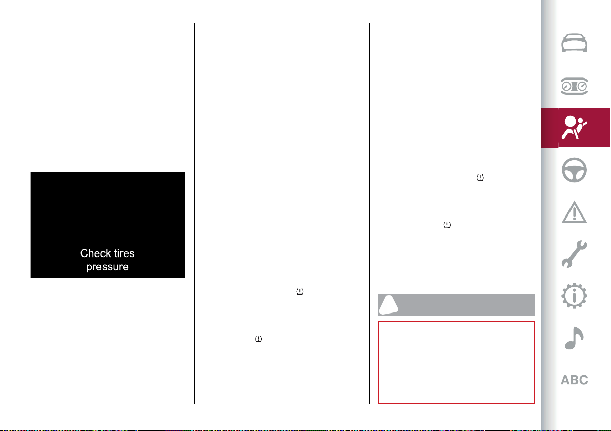
93
Monitoring System (TPMS), which
can advise the driver in the event of
insufficient tyre pressure according to
the cold inflation pressure set by the
driver (see indications in the "Technical
specifications" chapter, "Cold tyre
inflation pressure" table).
The system comprises a radio-frequency
transmitter sensor fitted to each wheel
(on the rim inside the tyre), which is able
to send information on the inflation
pressure of each tyre to the control
modulefig.79.
79 06016S0009EM
Inflation pressure varies in relation to
temperature by about (0.07 bar) every
43.7 °F (6.5 °C). This means that when
the outdoor temperature falls, the tyre
pressure decreases. Always adjust the
tyre inflation pressure when cold. This
is defined as the tyre pressure after at
least 3 hours of car inactivity or travel of
less than 1 mile (1.6 km) after the 3 hour
interval.
The cold tyre inflation pressure must not
exceed the maximum pressure indicated
on the shoulder of the tyre: for further
details see the instructions in the "Rims
and tyres" paragraph, in the "Technical
data" chapter.
Tyre pressure increases when the
vehicle is driven. This is normal, and no
adjustment of the pressure is required.
The TPMS signals the driver a possible
insufficient pressure if this falls below
the warning limit for any reason,
including the effects of low temperature
and normal loss of pressure from the
tyre.
The TPMS will stop indicating
insufficient tyre pressure when it is equal
to or greater than the prescribed cold
inflation pressure.
Therefore, if insufficient tyre pressure is
indicated ( warning light on instrument
panel on), increase the inflation pressure
up to the prescribed cold inflation value.
The system automatically updates and
warning light switches off each
time the system receives the updated
inflation pressures. The vehicle might
need to be driven at a speed higher
than about 15.5 mph (25 km/h) up to 20
minutes for the TPMS to receive this
information.
Operating example
Supposing that the prescribed cold
inflation pressure (i.e. vehicle stationary
for at least 3 hours) is 33.4 psi (2.3 bar), if
the ambient temperature is 68°F (20°C)
and the detected tyre pressure is 28.3 psi
(1.95 bar), a temperature reduction of
19.4°F (−7°C) results in a decrease in tyre
pressure, bringing it to approximately
24 psi (1.65 bar).
This pressure is sufficiently low to
activate the warning light .
Heating of tyres due to driving the
car may increase tyre pressure up to
approximately 28.3 psi (1.95 bar), but
the warning light will stay on. In this
situation, the warning light will switch off
only after the tyres are inflated to the
prescribed cold pressure value for the
car.
WARNING
54) When driving on two-way roads where
there is no lane dividing centre line (e.g. on
country roads), the use of the ABSA, HAS,
TJA, LKA systems is strongly discouraged
as this system could detect the entire
carriageway as single-lane dividing lines.
55) The driving assistance systems are
designed to help driving the car. The driver

SAFETY
94
must always maintain a sufficient level of
attention to the traffic and road conditions
and for controlling the trajectory of the car.
56) The system is an aid for car driving, it
DOES NOT warn the driver about incoming
cars outside of the detection areas. The
driver must always maintain a sufficient
level of attention to the traffic and road
conditions and for controlling the trajectory
of the car.
57) The accident risk persists despite the
application of torque to the steering wheel
by the ABSA system.
58) Applying a torque that corrects the
steering wheel stroke does not always
prevent an accident. It is always the
driver's responsibility to steer, brake or
accelerate, especially after the ABSA
system warning or after the steering wheel
torque intervention. It is also recommended
to always keep a safe distance to the sides.
Failure to comply with these precautions
may cause serious accidents and injuries.
59) In some cases, the system could apply
an improper torque to the steering wheel.
This application can be interrupted at
any time turning the steering wheel in the
opposite direction.
60) The system has not been designed
to prevent impacts and cannot detect
possible conditions leading to an accident in
advance. Failure to take into account this
warning may lead to serious or fatal injuries.
61) The system may be activated, assessing
the trajectory of the car, in case of
reflecting metal objects different from
other cars, such as safety barriers, road
signs, barriers before parking lots, tollgates,
level crossings, gates, railways, objects near
road constructions sites or higher than the
car (e.g. a flyover). In the same way, the
system may intervene inside multi-storey
car parks or tunnels, or due to a glare on the
road surface. These possible activations are
a consequence of the real driving scenario
coverage by the system and must not be
regarded as faults.
62) The system has been designed for
road use only. If the vehicle is driven on a
track, the system must be deactivated to
avoid unnecessary warnings. Automatic
deactivation is signalled by the dedicated
warning light/symbol switching on in the
instrument panel (see the instructions in the
"Warning lights and messages" paragraph,
"Knowing the instrument panel" chapter).
63) The system is an aid for the driver,
who must always pay full attention while
driving. The responsibility always rests with
the driver, who must take into account
the traffic conditions in order to drive in
complete safety. The driver must always
maintain a safe distance from the vehicle in
front.
64) If the driver depresses the brake pedal
fully or carries out a fast steering during
system operation, the automatic braking
function may stop (e.g. to allow a possible
manoeuvre to avoid the obstacle).
65) The system intervenes on vehicles
travelling in the same lane. People, animals
and things (e.g. pushchairs) are not taken
into consideration.
66) If the car must be placed on a roller
bench for maintenance or if it is washed
in an automatic car wash with an obstacle
in the front part (e.g. another car, a wall or
another obstacle), the system may detect
its presence and activate. In this case the
system must be deactivated through the
settings of the Connect system.
67) The presence of the TPMS does not
permit the driver to neglect regular checks
of the tyre pressure, including for the spare
tyre, and correct maintenance: the system is
not used to signalling a possible tyre fault.
68) Tyre pressure must be checked with
tyres rested and cold. Should it become
necessary for whatever reason to check
pressure with warm tyres, do not reduce
pressure even though it is higher than the
prescribed value. Repeat the check when the
tyres are cold.
69) Should one or more wheels be fitted
without sensors, the system will no longer
be available and a warning message will
be shown on the display, until wheels with
sensors are fitted again.
70) The TPMS cannot indicate sudden tyre
pressure drops (e.g. if a tyre bursts). In this
case, stop the car, braking with caution and
avoiding abrupt steering.
71) Changes in outside temperature may
cause tyre pressures to vary. The system
may temporarily indicate insufficient
pressure. In this case, check the tyre
pressure when cold and, if necessary,
restore the inflation values.
72) Replacing standard tyres with winter
tyres and vice versa requires TPMS system
adjustment that must only be performed by
Alfa Romeo Dealerships.
73) When a tyre is removed, it is advisable
to replace the rubber valve seal as well:
contact an Alfa Romeo Dealership. The
fitting/removal of the tyres and/or rims
require special care. To avoid damaging or
fitting the sensors incorrectly, tyre and/or
95
rim fitting/removal operations should only
be carried out by specialised staff. Contact
an Alfa Romeo Dealership.
IMPORTANT
19) The system may have limited operation
or not work at all in weather conditions such
as: heavy rain, hail, thick fog, heavy snow.
20) The section of the bumper in front the
sensor must not be covered with stickers,
auxiliary headlights or any other object.
21) System intervention might be
unexpected or delayed when other cars
transport loads projecting from the side,
above or from the rear, with respect to the
normal size of the car.
22) Operation can be adversely affected by
any structural change made to the car, such
as a modification to the front geometry,
tyre change, or a heavier load than the
standard load of the car.
23) Incorrect repairs made on the front
part of the car (e.g. bumper, chassis) may
alter the position of the radar sensor, and
adversely affect its operation. Go to an Alfa
Romeo Dealership for any operation of this
type.
24) Do not tamper with or carry out any
intervention on the radar sensor or on the
camera on the windscreen glass. In the
event of a sensor failure, contact an Alfa
Romeo Dealership.
25) Do not wash with high-pressure jets in
the bumper lower area: in particular do
not operate on the system's electrical
connector.
26) Be careful in the case of repairs and
new paintings in the area around the sensor
(panel covering the sensor on the left side
of the bumper). In the event of a frontal
collision the sensor may automatically
deactivate and display a warning to indicate
that the sensor needs to be repaired. Even
without a malfunction warning, deactivate
the system operation if you think that the
position of the radar sensor has changed
(e.g. due to low-speed frontal collision as
during parking manoeuvres). In these cases,
go to an Alfa Romeo Dealership to have the
radar sensor realigned or replaced.
27) When towing a trailer, a car or during
loading manoeuvres on a car transporter
(or in car for transport), the system must be
deactivated via the Connect system.
28) The Tyre Repair Kit, provided with the
car, is compatible with the TPMS sensors.
Using sealants different from that in the
original kit may compromise its operation.
If sealants not equivalent with the original
one are used, it is recommended to have
the TPMS sensor operation checked by a
qualified repair centre.
29) The TPMS is designed for original tyres
and wheels. The prescribed pressures and
consequent alarm thresholds set in the
TPMS are based on the dimensions of the
tyres fitted on the car. Using spare wheels
of a size, type and/or design different from
the original ones may cause an irregular
operation of the system and damage the
sensors. Aftermarket fitted wheels may
damage the sensors. Using aftermarket
tyre sealants may damage the Tyre
Pressure Monitoring System (TPMS) sensor.
If aftermarket tyre sealant is used it is
recommended to go to an Alfa Romeo
Dealership to have the sensors checked.
After checking or adjusting the tyre of the
pressure, always refit the valve cap to
prevent humidity and dirt from entering,
these may damage the Tyre Pressure
Monitoring System sensor.
DAA (Driver Attention Assist)
SYSTEM
(where provided)
It is a driving assistance system that can
detect the driver’s fatigue.
74)
ACTIVATION / DEACTIVATION
The system can be
activated/deactivated using the "Driver
Assistance" menu and then selecting
"Safety" on the Connect system.
SYSTEM INTERVENTION
Using information from the front camera,
the system implements two operating
logics:
the first operating logic takes the
driving style into account, observing
the road and detecting to what extent
the driver can continue driving with
few oscillations and few lane marking
crossing events;
SAFETY
96
the second operating logic measures
the time spent behind the wheel with
the vehicle speed is above 60 km/h and
below 180 km/h. If the "Standard" option
is selected, in these conditions, the "dozy
driver" message may appear after 3
hours of driving. If the "Early" option is
selected and these conditions occur, the
"dozy driver" message will be displayed
after 2 hours of driving.
NOTE If the conditions described above
are not detected continuously during the
entire driving period, the "dozy driver"
message may be displayed later than 2 or
3 hours. If the driving style indicates that
the driver is unable to follow the road
trajectory and respect the horizontal
lane markings, the red symbol fig.80
with a cup will appear on the instrument
panel display to suggest that the driver
should stop for a break. An auditory
signal is also emitted.
If the driver accepts the suggestion
provided by the system by pressing
the MENU button on the left steering
wheel stalk and stopping for a pause, the
message will disappear from the display
and the symbol will be displayed in
the dedicated area of the instrument
panel display fig. 79 up to the next engine
shutdown/restart.
If the driver ignores the warning
provided by the system and does not
stop, the message will continue to
remain on the display, together with the
symbol in the dedicated area of the
instrument paneldisplay fig. 81.
In the second case, a dedicated message
is shown on the instrument panel display
and disappears automatically after a few
seconds.
In the event of a primary intervention,
with the symbol (red) shown on the
display, the secondary event is not
considered/monitored.
WARNING If the ABS system activates,
the word "ABS ACTIVE" will be displayed
instead of the symbol (red) and it
will remain active until the ABS system
finishes its operation.
WARNING In the event of a system fault,
the amber symbol appears on the
instrument panel display together with a
dedicated message.
Changing the system sensitivity
The system intervention sensitivity can
be adjusted using the "Driver Assistance"
menu and then selecting "Safety" on the
Connect system.
WARNING If the "RACE" mode is used
(where provided), the DAA system is
automatically deactivated and it will
therefore not be possible to change its
sensitivity.
WARNING In the case of camera failure,
the system sensitivity cannot be
changed.
WARNING
74) The DAA system is an aid for driving and
does not relieve the driver of responsibility
for driving the car. If you experience fatigue
while driving, pull over safely for a break
without waiting for the DAA to intervene.
Only get back on the road when you are in
81 07076S0713EM
80 07076S0712EM
97
the right physical and mental condition to
prevent endangering yourself and other
road users.
OCCUPANT PROTECTION
SYSTEMS
The following protection systems are
among the vehicle’s most important
safety equipment:
seat belts;
SBA (Seat Belt Alert) system;
head restraints;
child restraint systems;
Front airbags and side bags.
Read the information given the following
pages with the utmost care. It is of
fundamental importance that the
protection systems are used in the
correct way to guarantee the maximum
possible safety level for the driver and
the passengers.
For the description of the head restraint
adjustment see the "Head restraints"
paragraph in the "Knowing your car"
chapter.
SEAT BELTS
All the seat belts have three anchor
points and a retractor.
The reel mechanism operates locking
the belt in the event of sharp braking or
strong deceleration due to an impact.
This allows the belt strap to slide freely
and to adapt to the body of the occupant.
In the event of an accident, the belt will
lock reducing the risk of impact inside
the passenger compartment and of being
projected outside the car.
The driver is responsible for respecting,
and ensuring that all the other occupants
of the vehicle also respect, the local laws
in force in relation to the use of the seat
belts.
Always fasten the seat belts before
setting off.
USING THE SEAT BELTS
The seat belt should be worn keeping
the chest straight and rested against the
backrest.
To fasten the seat belts, hold fastening
tongue(1)fig.82 and insert itintobuckle
(2), until it clicks into place.
82 06056V0001EM
On removal of the belt, if it jams, let it
rewind for a short stretch, then pull it out
again without jerking.
To unfasten the seat belts, press button
3 and guide the seat belt with your hand
while it is rewinding, to prevent it from
twisting.
75)
The retractor may lock when the car is
parked on a steep slope: this is perfectly
normal. Furthermore, the reel mechanism
locks the belt if it is pulled sharply or in
the event of sudden braking, collisions
and high-speed bends.
Wear the rear seat belts as shown in
fig.83 and fig.84.
SAFETY
98
83 06056V0005EM
84 06056S0003EM
76)
ADJUSTING THE SEAT BELT HEIGHT
Four different adjustments in height are
possible.
To adjust the window height, from the
top downwards, press the button (4)
fig.85 andslidethe handledownwards.
The height adjuster moves upwards even
without pressing the button.
Always adjust the height of the seat
belts to fit the person wearing it: this
precaution could greatly reduce the risk
of injury in the event of a crash.
Correct adjustment is obtained when
the belt passes approximately half way
between the shoulder and the neck.
85 06056V0002EM
77) 78)
WARNING
75) Never press button (3) when travelling.
76) Remember that in the event of an
accident, the rear seat passengers not
wearing seat belts are exposed to a very
serious risk and also represent a serious
danger for the front seat occupants.
77) Make height adjustment of the seat
belts when the car is stationary.
78) After height adjustment, always check
that the cursor to which the ring is fastened
is locked in one of the preset positions.
To do this, with the adjustment button
released, exert further pressure downwards
to allow the locking device to click if the grip
has not been released in one of the possible
positions.
SBA (Seat Belt Alert) SYSTEM
The SBR system warns the passengers
of the front and rear (where provided)
seats if their seat belt is not fastened.
The system warnings unfastened seat
belts with visual warnings (warning lights
on in the instrument panel and icons on
the display) and an acoustic warning (see
the following paragraphs).
FRONT SEAT BELT WARNING LIGHT
BEHAVIOUR
When the ignition device is turned to the
ON position, warning light (seefig.86)
comes onfor a few seconds,regardless
of the status of the front seat belts.
With vehicle at a standstill, if the driver
side seat belt or the passenger side
seat belt (with occupant seated) is
unfastened, the warning light stays on
constantly.
99
86 06066S0001EM
As soon as the threshold of 5 mph
(8 km/h) is exceeded for a few
seconds (variable according to the car
conditions) with driver or passenger
side (with passenger seated) seat belts
unfastened, an acoustic warning is
activated together with the flashing of
the warning light for approximately
105 seconds.
When this cycle of warnings is activated
it will stay on for its entire length
(regardless of the car speed) or until the
seat belts are fastened again.
When the reverse is engaged, during the
cycle of warnings, the acoustic signal
is deactivated and the warning light
turns on fixed. The cycle of warnings
will be reactivated as soon as the speed
exceeds 5 mph (8 km/h) again.
REAR SEAT BELT ICON BEHAVIOUR
(where provided)
The icons are shownonthedisplayfig. 87
after a few seconds have elapsed since
the ignition device is turned to ON and
disappear after approximately 30
seconds.
After a door closes, or following a change
in belt fastening status, the icons are
shown again for approximately 30
seconds before disappearing.
The icons shown on the display indicate:
(1) - rear left seat belt;
(2) - rear central seat belt (where
provided);
(3) - rear right seat belt.
87 06066S0002EM
The icons are displayed according to
the corresponding seat belts in the rear
seats, and stay on for about 30 seconds
from the last seat belt status change:
if the seat belt is fastened the
corresponding icon will be green;
if the seat belt is unfastened the
corresponding icon will be red.
If a rear seat belt is unfastened, an
acoustic warning (3 "beeps") will be
activated along with the relevant icon
lighting up in the display.
Furthermore the icons will light up again
for 30 seconds each time one of the rear
doors is closed.
The visual indication (flashing red) will
start and stop independently for each
warning light if several seat belts are
unfastened.
The icon will turn green after the
corresponding seat belt has been
fastened.
The rear seat icons will go out, regardless
of the state of the belt (red icon or green
icon), approximately 30 seconds after
the last signal.
IMPORTANT NOTES
As far as the rear seats are concerned,
the SBA system will only indicate
whether the seat belts are unfastened
(red icon) or fastened (green icon), not
the presence of any passengers.
The warning lights/icons all stay off if all
seat belts (front and rear) are fastened
when the ignition device is set to ON.
For the rear seats, the icons will activate
a few seconds after the ignition device
has been turned to ON, regardless of the

SAFETY
100
status of the seat belts (even if the seat
belts are all fastened).
All the warning lights/icons will come
on when at least one belt changes from
fastened to unfastened status or vice
versa.
PRE-TENSIONERS
The car is equipped with front and rear
lateral seat belt pretensioners, which
draw back the seat belts by several
centimetres in the event of a strong
frontal impact. This guarantees the
perfect adherence of the seat belts
to the occupant's bodies before the
retention action begins.
It is evident that the pretensioners have
been activated when the belt withdraws
toward the retractor.
This car is also equipped with a second
pretensioner on the front seat belts
(fitted in the kick plate area). Its
activation is signalled by the shortening
of the metal cable.
A slight discharge of smoke may be
produced during the activation of the
pretensioner which is not harmful and
does not involve any fire hazard.
The pretensioner does not require any
maintenance or lubrication: any changes
to its original conditions will invalidate
its efficiency.
If, due to unusual natural events (floods,
sea storms, etc.), the device has been
affected by water and/or mud, contact
an Alfa Romeo Dealership to have it
replaced.
WARNING To obtain the highest degree
of protection from the action of the
pretensioner, wear the seat belt tight to
the torso and pelvis.
LOAD LIMITERS
79)
30)
To increase safety in the event of an
accident, the front and rear lateral seat
belt retractors contain a load limiter
which controls the force acting on the
chest and shoulders during the belt
restraining action in the event of a
head-on collision.
GENERAL INSTRUCTIONS FOR USING
THE SEAT BELTS
80) 81) 82)
Respect and ensure that all the other
occupants of the vehicle comply with the
local laws in force regarding the use of
seat belts. Always fasten the seat belts
before setting off.
Seat belts must also be worn by pregnant
women: the risk of injury in the event of
an accident is reduced for them and the
unborn child if they are wearing a seat
belt.
Pregnant women must position the
lower part of the belt very low down so
that it passes over the pelvis and under
the abdomen fig. 88.While pregnancy
progresses, the driver must adjust both
seat and steering wheel to have full
control over the vehicle (pedals and
steering wheel must be easy to access).
The maximum clearance should be kept
between the abdomen and the steering
wheel.
88 06076S0001EM
The seat belt strap must not be twisted.
The upper part must pass over the
shoulder and cross the chest diagonally.
The lower part must adhere to the
pelvisfig. 89,nottotheabdomenof
the occupant. Never use devices (clips,
clamps, etc.) that hold the seat belt away
from your body.
101
89 06076S0002EM
Each seat belt must be used by only one
person. Never travel with a child sitting
on the passenger's lap and a single belt
toprotect them bothfig.90. Ingeneral,
do not place any objects between the
person and the belt.
90 06076S0003EM
SEAT BELTS MAINTENANCE
For keeping the seat belts in efficient
conditions, carefully observe the
following warnings:
always use the seat belt well stretched
and never twisted; make sure that it is
free to run without obstructions;
check seat belt operation as follows:
attach the seat belt and pull it hard;
replace the seat belt after an accident
of a certain severity even if it does not
appear to be damaged. Always replace
the seat belt if the pretensioners were
deployed;
prevent the retractors from getting
wet: their correct operation is only
guaranteed if water does not get inside;
replace the seat belt when it shows
wear or cuts.
WARNING
79) The pretensioner may be used only once.
After its activation, contact an Alfa Romeo
Dealership to have it replaced.
80) Removing or otherwise tampering with
pretensioner and seat belt components is
strictly prohibited. Any intervention on
these components must be performed
by qualified and authorised technicians.
Always contact an Alfa Romeo Dealership.
81) For maximum safety, keep the backrest
upright, lean back into it and make sure the
seat belt fits closely across your chest and
pelvis. Always fasten the seat belts for both
the front and rear seats! Travelling without
wearing seat belts will increase the risk of
serious injury and even death in the event of
an accident.
82) If the belt has been subjected to high
levels of stress, for example after an
accident, it should be changed completely
together with the attachments, attachment
fixing screws and the pretensioner. In fact,
even if the belt has no visible defects, it may
have lost its resilience.
IMPORTANT
30) Operations which lead to impacts,
vibrations or localised heating (over 100°C
for a maximum of six hours) in the area
around the pretensioner may cause damage
or make it deploy. Contact an Alfa Romeo
Dealership should intervention be necessary
on these components.
CHILD RESTRAINT SYSTEMS
CARRYING CHILDREN SAFELY
83) 84) 85) 86)
For optimal protection in the event of
an impact, all occupants must be seated
and wearing adequate restraint systems,
including newborn and other children!
This prescription is compulsory in all
EC countries according to EC Directive
2003/20/EC.
Children below the height of 4.9 ft
(1.50 metres) and up to 12 years must
be protected with suitable restraint
systems and be seated on the rear seats.
SAFETY
102
Statistics on accidents indicate that
the rear seats offer greater safety for
children.
Compared with an adult, a child's head
is larger and heavier in proportion to
their body and the child's muscular and
bone structures are not fully developed.
Therefore, correct restraint systems
other than adult seat belts are necessary,
to reduce as much as possible the risk
of injuries in the event of an accident,
braking or sudden manoeuvre.
Children must be seated safely
and comfortably. As far as the
characteristics of the child seats used
allow, you are advised to keep children
in rear facing child seats for as long as
possible (at least until 3–4 years old),
since this is the most protected position
in the event of an impact.
The choice of the most suitable child
restraint system depends on the weight
and size of the child. There are various
types of child restraint systems, which
can be secured to the car by means of
the seat belts or with the ISOFIX/i-Size
anchorages.
It is recommended to always choose
the restraint system most suitable for
the child; for this reason always refer to
the Owner Handbook provided with the
child restraint system, to be sure that it
is of the right type for the children it is
intended for.
In Europe the characteristics of child
restraint systems are ruled by the
regulation ECE-R44, dividing them into
five weight groups:
Group Weight groups
Group 0
up to 22 lb (10 kg) in
weight
Group 0+
up to 28.7 lb (13 kg)
in weight
Group 1
20 - 40 lb (9 - 18 kg)
in weight
Group 2
33 - 55 lb (15 - 25 kg)
in weight
Group 3
48.5 - 79.4 lb (22 -
36 kg) in weight
The ECE-R44 standard was recently
paired with the ECE R-129 regulation,
which defines the characteristics of
the new i-Size child restraint systems
(see the "Suitability of passenger seats
for i-Size child restraint system use"
paragraph for more information).
All restraint devices must bear the type-
approval data, together with the control
mark, on a label solidly fixed to the child
restraint system which must never be
removed.
Lineaccessori includes child restraint
systems for each weight group. These
devices are recommended having been
specifically tested for Alfa Romeo cars.
WARNING For correct installation on
the car, some universal child restraint
systems require an accessory (base) sold
separately by the restraint system's
producer. Therefore, FCA advises
customers to check that their chosen
child restraint system can be installed
on their vehicle by performing a trial
installation, on the vendor's premises,
before purchase.
INSTALLING A CHILD CARSEAT WITH
SEATBELTS
87) 88) 89) 90)
The Universal child restraint systems
installed with the seat belts only are
type-approved on the basis of the ECE
R44 standard and are divided into
various weight groups.
WARNING The figures are indicative and
provided for assembly purposes only. Fit
the child restraint system according to
the instructions, which must be included.
Group 0 and 0+
Infants up to 28.7 lb (13 kg) must be
carried with a rearward facing child
restraint system of the type shown in
fig. 91 which, supportingthehead,does
not induce stress on the neck in the event
of sudden decelerations.
103
91 06086V0001EM
The child restraint system is restrained
by the vehicle seat belts, as shown in
fig.91 andit mustrestrainthechild in
turn with its own belts.
Group 1
Children weighing from 20 to 40 lb (from
9 to 18 kg) may be transported in forward
facing child restraint systemsfig. 92.
92 06086V0002EM
Group 2
Children from 33 to 55 lb (from 15 to 25
kg) may be restrained directly by the car
seat belts fig.93.
93 06086V0003EM
In this case, the child restraint system
is used to position the child correctly
with respect to the seat belts so that
the diagonal belt section crosses the
child’s chest and not the neck, and the
lower part is snug on the pelvis not the
abdomen.
Group 3
For children from 48.5 to 79.4 lb (from 22
to 36 kg), there are restraining devices
that allow the seat belts to pass through
properly.
The fig.94shows the correct child
positioning on the rear seat.
94 06086V0004EM
Children over 4.9 ft (1.50 m) tall wear
seatbelts like adults.
WARNING
83) SEVERE DANGER When a passenger
front airbag is fitted, do not install rearward
facing child restraint systems on the front
passenger seat. Deployment of the airbag in
a crash could cause fatal injuries to the child
regardless of the severity of the collision.
It is advisable to always carry children in
a child restraint system on the rear seat,
which is the most protected position in the
event of a collision.
84) On the sun visor there is a label with
suitable symbols reminding the user that
it is compulsory to deactivate the airbag if
a rearward facing child restraint system is
fitted. Always comply with the instructions
on the passenger side sun visor (see the
"Supplementary Restraint System (SRS) -
Airbag" paragraph).
SAFETY
104
85) Should it be necessary to carry a
child on the passenger side front seat
in a rear facing child restraint system,
the passenger side front air bag and
side bag must be deactivated through
the Connect system main menu (see the
Supplementary Restraint System (SRS) -
Air bag" paragraph), verifying deactivation
by checking whether the OFF LED has
illuminated on the front courtesy light. Move
the passenger's seat as far back as possible
to avoid contact between the child seat and
the dashboard.
86) Do not move the front or rear seat if a
child is seated on it or on the dedicated child
restraint system.
87) Incorrect fitting of the child restraint
system may result in an inefficient
protection system. In the event of an
accident the child restraint system may
become loose and the child may be injured,
even fatally. When fitting a restraint system
for newborns or children, strictly comply
with the instructions provided by the
Manufacturer.
88) When the child restraint system is not
used, secure it with the seat belt or with
the ISOFIX anchorages, or remove it from
the car. Do not leave it unsecured inside the
passenger compartment. In this way, in the
event of sudden braking or an accident, it
will not cause injuries to the occupants.
89) After installing a child restraint system,
do not move the seat: always remove the
child restraint system before making any
adjustment.
90) Always make sure that the chest
section of the seat belt does not pass under
the arms or behind the back of the child. In
the event of an accident the seat belt will
not be able to secure the child, with the risk
of injury, including fatal injury. Therefore
the child must always wear the seat belt
correctly.
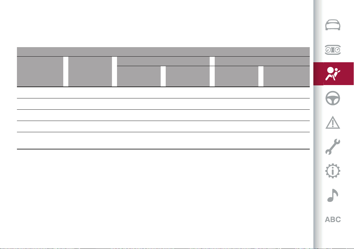
105
PASSENGER SEAT COMPLIANCE WITH REGULATIONS ON UNIVERSAL CHILD RESTRAINT SYSTEM USE
The car complies with European Directive 2000/3/EC which governs the arrangement possibilities for child restraint systems on the
various seats of the car as shown in the following table:
Positioning the “Universal” child restraint system
Group Weight groups
Front passenger Rear passengers
Passenger airbags
on
Passenger airbags
off
Rear central
passenger (where
provided)
Rear side passengers
Group 0 up to 22 lb (10 kg) X U U U
Group 0+ up to 26.7 lb (13 kg) X U U U
Group 1 20 - 40 lb (9 - 18 kg) X U U U
Group 2 33 - 55 lb (15 - 25 kg) U U U U
Group 3
48.5 - 79.4 lb (22 - 36
kg)
U U U U
X = Restraint system not suitable for children in this weight category.
U = suitable for child restraint systems of the “Universal” category, according to European Standard EEC-R44 for the specified “Groups”.

SAFETY
106
INSTALLING AN ISOFIX CHILD
RESTRAINT SYSTEM
91) 92) 93) 94) 95)
The rear side seats of the car are
equipped with ISOFIX attachments, for
fitting child restraint systems quickly,
simply and safely.
The ISOFIX system lets you install the
ISOFIX child restraining system without
using the car seat belts but connecting
them directly to the carseat with three
anchors in the car.
Traditional child restraint systems can
be fitted alongside ISOFIX child restraint
systems on different seats in the same
vehicle.
To install an ISOFIX child restraint
system, attach it to the two metal
anchors fig.95.Theycanbereachedby
lifting the flaps 2 located behind the rear
seat cushion, at the point where it meets
the backrest. Then fix the upper hook
(available with the child restraint system)
to the dedicated "top tether" anchor
fig. 96 locatedbehindthe seatbackrest.
95 06086V0009EM
96 06086V0005EM
fig.97 shows anexample ofaUniversal
ISOFIX child restraint system for weight
group 1.
WARNINGThe fig.97 isindicativeand
for assembly purposes only. Fit the
child restraint system according to the
instructions, which must be included.
97 06086V0006EM
NOTE When a Universal ISOFIX child
restraint system is used, only ECE R44
"ISOFIX Universal" (R44/03 or further
upgrades) type-approved child restraint
systems can beused(see fig.98).
The other weight groups are covered by
specific ISOFIX child restraint systems,
which can be used only if specifically
tested for this car (see list of cars
provided with the child restraint system).
98 06086S0007EM
107
WARNING
91) Do not use the same lower anchoring to
install more than one child restraint system.
92) If a Universal ISOFIX child restraint
system is not fixed to all three anchorages,
it will not be able to protect the child
correctly. In a crash, the child could be
seriously or fatally injured.
93) Fit the child restraint system when the
car is stationary. The child restraint system
is correctly secured to the brackets when
you hear the click. Follow the instructions
for assembly, disassembly and positioning
that the Manufacturer must supply with the
child restraint system.
94) If the car was involved in an accident
of a certain severity, have the ISOFIX
anchorages and the child restraint system
replaced.
95) If the car was involved in an accident
of a certain severity, have both the child
restraint system and the seat belt it was
attached to replaced.
SAFETY
108
SUITABILITY OF PASSENGER SEATS FOR ISOFIX CHILD RESTRAINT SYSTEM USE
ISOFIX POSITIONS ON THE CAR
Weight categories Size category Device Front passenger
Rear side
passengers
Rear central
passenger
(where provided)
Group 0 (up to 22 lb / 10 kg) E ISO/R1 X IL X
Group 0+ (up to 28.7 lb / 13
kg)
E ISO/R1 X IL X
D ISO/R2 X IL X
C ISO/R3 X IL (*) X
Group 1 (from 20 to 40 lb /
from 9 to 18 kg)
D ISO/R2 X IL X
C ISO/R3 X IL (*) X
B ISO/F2 X IUF – IL X
B1 ISO/F2X X IUF – IL X
A ISO/F3 X IUF – IL X
Group 2 (from 33 to 55 lb /
from 15 to 25 kg)
X IL X
109
ISOFIX POSITIONS ON THE CAR
Weight categories Size category Device Front passenger
Rear side
passengers
Rear central
passenger
(where provided)
Group 3 (from 48.5 to 79.4
lb / from 22 to 36 kg)
X IL X
X ISOFIX position not suitable for ISOFIX child protection systems for this weight and/or size category.
IL Suitable for ISOFIX child restraint systems of the "Specific for the vehicle", "Restricted", or "Semiuniversal" categories, approved for this type of
vehicle.
(*) For Quadrifoglio versions only. It is possible to install the ISOFIX child restraint system by adjusting the front seat (adjustment is not required if
the "Sparco" Carbonshell Sport seats are installed).
IUF Suitable for forward facing ISOFIX child restraint systems of the universal category, approved for use in the weight group.

SAFETY
110
i-Size CHILD RESTRAINT SYSTEMS
The rear side seats of the car are type-
approved to house the state-of-the-art
i-Size child restraint systems.
These child restraint systems, built and
type-approved according to the i-Size
(ECE R129) standard, ensure better
safety conditions to carry children on
board a vehicle:
the child must be transported
rearward facing until 15 months;
child restraint system protection is
increased in the event of a side collision;
the use of the ISOFIX system is
promoted to avoid faulty installation of
the child restraint system;
efficiency in the choice of the child
restraint system, which isn't made
according to weight any more but
according to the child's height, is
increased;
compatibility between the vehicle
seats and the child restraint systems is
better: the i-Size child restraint systems
can be considered as "Super ISOFIX"; this
means that they can be perfectly fitted
in type-approved i-Size seats, but can
also be fitted in ISOFIX (ECE R44) type-
approved seats.
NOTE If your car seats are i-Size
approved, the symbolshown infig.99
will appear on the seats near the ISOFIX
attachments.
99 06086S0008EM
NOTE See the table shown on the
following page to check whether your
car is approved for installing i-Size child
restraint systems.
111
The following table, according to European standard ECE 129, indicates the possibility of i-Size child restraint system installation.
i-Size POSITIONS ON THE CAR
Device Front passenger Rear side passengers Rear central passenger
i-Size child restraint systems
ISO/R2 X i-U X
ISO/F2 X i-U X
i-U: suitable for Universal i-Size child restraint systems, both rearward facing and forward facing.
X: seat not suitable for Universal i-Size child restraint systems.
SAFETY
112
CHILD RESTRAINT SYSTEMS RECOMMENDED BY ALFA ROMEO FOR THE STELVIO
Lineaccessori Alfa Romeo includes a complete range of child restraint systems to be fixed using the seat belt with three anchorage
points or the ISOFIX anchorages.
WARNING Alfa Romeo recommends fitting the child restraint system according to the instructions, which must be included.
Weight group Child restraint system Type of child restraint system Child restraint system installation
Group 0+: from birth to 28.7
lb (13 kg) from 15.7 to 33.5 in
(from 40 to 85 cm)
PEG-PEREGO
Primo Viaggio SL
Universal/ISOFIX child restraint system.
It must be installed rearward facing,
using the vehicle seat belts only, or the
dedicated ISOFIX K base (which can be
purchased separately) and the vehicle ISOFIX
anchorages.
Alfa Romeo recommends using the specific
ISOFIX K base (which can be purchased
separately) and the ISOFIX anchorages of
the vehicle to install it.
With the base it must be fitted on the rear
outer seats.
ISOFIX Basic 0+1 K
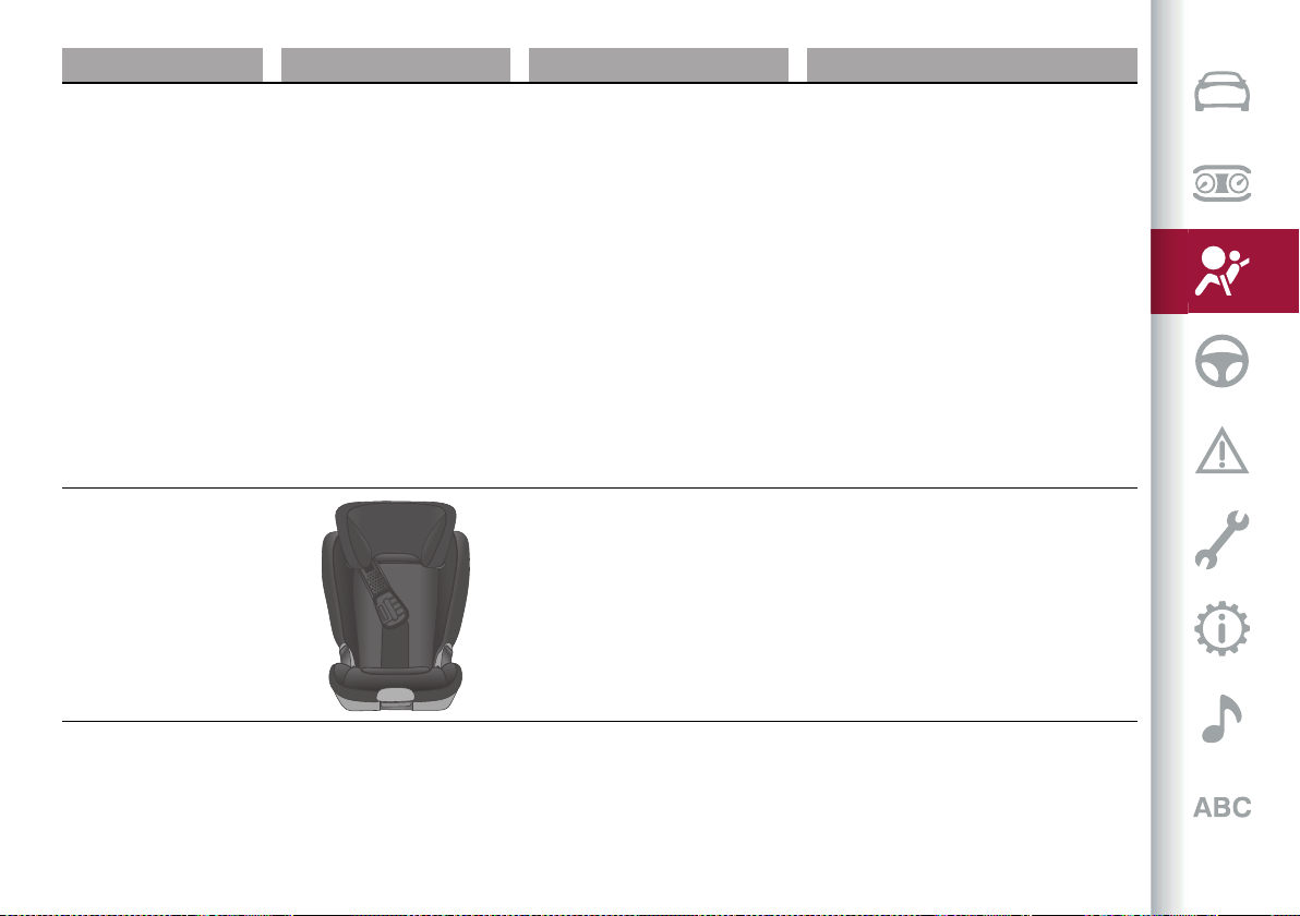
113
Weight group Child restraint system Type of child restraint system Child restraint system installation
Group 0+/1: from birth to
28.7 lb (13 kg) from 15.7 to
33.5 in (from 40 to 85 cm)
+
BeSafe iZi Modular i-Size
Order code AR:
71808565
+
BeSafe iZi Modular i-Size Base
Order code AR:
71808566
iSize type-approval child restraint system
which must be fitted on the car with the
iZi Modular iSize Base, to be purchased
separately. It can be installed facing forwards
or facing backwards (refer to the child
restraint system manual).
Group 2: from 33 to 55 lb
(from 15 to 25 kg) from 37.4
to 53 in (from 95 to 135 cm)
Britax Römer KidFix XP
It can only be fitted facing forwards, using
the three-point seat belt and the ISOFIX
anchorages of the vehicle.
Alfa Romeo recommends to install it using
the ISOFIX anchorages of the vehicle.
It must be fitted on the rear outer seats.
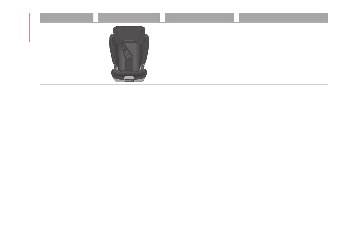
SAFETY
114
Weight group Child restraint system Type of child restraint system Child restraint system installation
Group 3: from 48.5 to 79.4
lb (from 22 to 36 kg) from
53.3 to 59 in (from 136 to
150 cm)
Britax Römer KidFix XP
It can only be fitted facing forwards, using
the three-point seat belt and the ISOFIX
anchorages of the vehicle.
Alfa Romeo recommends to install it using
the ISOFIX anchorages of the vehicle.
It must be fitted on the rear outer seats.
115
Main recommendations to carry
children safely
Install the child restraint systems
on the rear seat, which is the most
protected position in the event of an
impact.
Keep children in rearward facing child
restraint systems for as long as possible,
until 3–4 years old if possible.
The rear head restraint or the front
passenger head restraint can be lifted
if needed to install a child restraint
system. The head restraint must always
be present in the vehicle and fitted if
the seat is used by an adult passenger
or a child sitting in a restraint system
without backrest (refer to the procedure
described in ‘’Head restraint’’ paragraph,
‘’Knowing your vehicle’’ chapter).
If the front passenger airbag has
been deactivated, always check that the
warning light on the courtesy light is on
continuously to make sure that it is
effectively deactivated.
Carefully follow the instructions
supplied with the child restraint system.
Keep the instructions in the vehicle
along with the other documents and this
handbook. Do not use second-hand child
seats without instructions.
Only one child is to be strapped into
each restraint system; never carry two
children using one child restraint system.
Always check that the seat belts do
not rest on the child’s neck.
Always check that the seat belt is well
fastened by pulling on it.
While travelling, do not let the child sit
incorrectly or unfasten the belts.
Never allow a child to put the belt's
diagonal section under an arm or behind
their back.
Never carry children on your lap, even
newborns. No-one can hold a child in the
case of a crash.
In the event of an accident, replace the
child restraint system with a new one.
SUPPLEMENTARY RESTRAINT
SYSTEM (SRS) - AIRBAG
The car is equipped with:
front driver airbag;
front passenger airbag;
driver and passenger front side bags
for pelvis, chest and shoulder protection
(Side bags);
side bags for head protection of front
seat passengers and rear side seat
passengers (window bag).
The location of the airbags on the vehicle
is marked by the word "AIRBAG" under
the Alfa Romeo emblem on the steering
wheel, on the dashboard, on the side trim
or on a label placed next to the airbag
deployment area.
FRONT AIRBAGS
The front (driver and passenger) airbags
protect the front seat occupants in the
event of head-on crashes of medium-
high severity, by placing the cushion
between the occupant and the steering
wheel or dashboard.
Therefore non-activation of airbags in
other types of collisions (side impacts,
rear shunts, roll-overs, etc.) does not
indicate a system malfunction.
Driver and passenger front airbags are
not a replacement of but complementary
to the seat belts, which should always be
worn, as specified by law in Europe and
most non-European countries.
In a crash, those not wearing a seat
belt are projected forwards and may
come into contact with the bag which
is still inflating. The protection offered
by the bag is compromised in these
circumstances.
Front airbags may not activate in the
following situations:
frontal impacts against highly
deformable objects not involving the
front surface of the car (e.g. wing
collision against guard rail, etc.);
vehicle wedging under other vehicles
or protective barriers (e.g. trucks or
guard rails).
Failure to activate in the conditions
described above is due to the fact that

SAFETY
116
they may not provide any additional
protection compared with seat belts, so
their activation would be inappropriate.
In these cases, non-deployment does not
indicate a system malfunction.
Front airbag driver's side
This consists of an instantly inflating
bag contained in a special recess in the
centreofthesteeringwheel fig.100.
100 06106V0020EM
Passenger's front airbag
This consists of an instantly inflating
bag contained in a special recess in the
dashboard fig. 101: this bag hasa larger
volume than that on the driver side.
101 06106V0002EM
Passenger's front airbag and child
restraint systems
Rearward-facing child restraint systems
must NEVER be fitted on the front seat
with an active passenger side airbag
since in the event of an impact the airbag
activation may cause fatal injuries to the
transported child.
ALWAYS comply with the instructions on
the label stuck on the passenger side sun
visorfig.102, and shownintableonthe
following pages.
102 06106V0003EM
Deactivating/activating the passenger
side air bags: front air bag and side bag
(where provided)
To deactivate the front and side
passenger side airbag, use the Connect
system. Select the following functions
in succession from the main Menu, and
activate them by pressing the fig. 101
button: "Settings", "Safety", "Passenger
Airbag". The system will check airbag
activation/deactivation status and
request confirmation of change of
status.
103 05036V0099EM
On the dashboard are the ON and OFF
LED status. Moving the ignition device to
MAR, the two LEDs switch on for a few
seconds. If not, contact an Alfa Romeo
Dealership. During the first seconds, the
activation of the LEDs does not actually
show the passenger protection status,
but only checks its correct operation.
117
After a test of a few seconds, the LEDs
will indicate the status of the passenger
airbag protection.
Passenger protection activated: the ON
LEDfig.104 switchesonfixed.
Passenger protection deactivated: the
OFF LED turns on fixed.
104 06106S0008EM

SAFETY
118
Passenger's front airbag and child restraint systems: IMPORTANT
103 J0A0215
119
SIDE BAGS
To help increase occupants protection
in the event of side impact collisions, the
vehicle is equipped with front side bags
and window bags.
Side bag
These comprise two bags located in
thefrontseatbackrestsfig.106 which
protect the pelvis, chest and shoulder
area of the occupants in the event of a
side collision of medium-high severity.
They are marked by the "AIRBAG" label
sewn on the outer side of the front seats.
106 06106V0004EM
Window bag
This consists of a "curtain" bag housed
behind the roof side linings and covered
byspecial trimsfig.107.
They are designed to protect the head of
front and rear occupants in the event of a
side collision, thanks to the wide cushion
inflation surface.
107 06106V0005EM
The deployment of side bags in the event
of side impacts of low severity is not
required.
In the event of a side impact, the
system provides best protection if the
passenger sits on the seat in a correct
position, allowing the window bag to
inflate correctly.
96) 97) 98) 99) 100) 101) 102) 103) 104) 105) 106) 107) 108)
109)
Important notes
Do not wash the seats with water or
pressurised steam (wash by hand or at
automatic seat washing stations).
The front airbags and/or side bags
may be deployed in the event of sharp
impacts to the underbody of the car (e.g.
impact with steps, pavements, potholes
or road bumps etc.).
When the airbag deploys it emits a small
amount of dust: the dust is harmless and
does not indicate the beginning of a fire.
The dust may irritate the skin and eyes
however: in this case, wash with neutral
soap and water.
Airbag checking, repair and replacement
must be carried out at an Alfa Romeo
Dealership.
If the car is scrapped, have the airbag
system deactivated at an Alfa Romeo
Dealership.
Pretensioners and airbags are deployed
in different ways on the basis of the type
of collision. Failure to activate one or
more of the devices does not indicate a
system malfunction.
WARNING
96) Do not apply stickers or other objects
on the steering wheel, on the dashboard
in the passenger side airbag area, on side
upholstery on the roof or on the seats.
Never put objects (e.g. mobile phones) on
the passenger's side dashboard since they
could interfere with correct inflation of the
airbag and also cause serious injury to the
passengers.
97) The airbag must be able to inflate
without obstruction in the event of
deployment. It is therefore recommended
not to drive with the body bent forward, but
to sit up resting your back and shoulders
on the backrest of the seat. Adjusting
the position of the seat so that you can
reach and manoeuvre the steering wheel
comfortably with your arms slightly bent
SAFETY
120
being as far away as possible from the
steering wheel. Being too close to the
steering wheel when the airbag is deployed
may cause serious injury.
98) The passenger airbag can be
deactivated on the Connect system
by selecting the following functions in
sequence on the main menu: “Settings”;
“Safety”; “Passenger air bag” and
“Deactivation”.
99) Do not affix rigid objects to the garment
hooks or support handles.
100) Do not rest your head, arms or elbows
on the door, on the windows or in the
window bag area to prevent injury during
deployment.
101) Never lean your head, arms or elbows
out of the window.
102) If when setting the ignition device to
ON the warning light does not turn on
or stays on whilst driving, a failure may
have occurred in the restraint systems. In
this case the air bags or pretensioners may
not be deployed in an impact or, in a lower
number of cases, they may be deployed
accidentally. Before continuing, contact an
Alfa Romeo Dealership immediately to have
the system checked.
103) In case of a LED OFF failure
(located on the front courtesy light), the
warning light appears on the instrument
panel.
104) On cars with side bags, do not cover the
front seat backrests with extra covers.
105) Do not travel with objects in your lap,
in front of your chest or held in your mouth
(e.g., pipe, pencil etc.). They could cause
severe injury if the airbag is deployed in a
crash.
106) If the car has been subject to theft,
attempted theft, vandalism, or flooding,
have the air bag system inspected at an Alfa
Romeo Dealership.
107) Malfunction of the airbag failure
warning light is indicated by the activation
of an airbag failure icon and a dedicated
message on the instrument panel display.
The pyrotechnic charges are not disabled.
Before continuing, contact an Alfa Romeo
Dealership immediately to have the system
checked.
108) The front airbag deployment threshold
is higher than that of the pretensioners. For
impacts whose intensity falls between the
two levels, normally, only the pretensioners
will be activated.
109) The airbag does not replace seat belts
but increases their efficiency. Because front
airbags are not deployed for low-speed
crashes, side collisions, rear-end shunts
or rollovers, occupants are protected, in
addition to any side bags, only by their seat
belts, which must therefore always be
fastened.

Let’s get to the core of the vehicle: seeing how you can exploit
all of its potential to the full. We’ll look at how to drive it safely
in any situation, so that it can be a welcome companion, with
our comfort and our wallets in mind.
STARTING AND DRIVING
STARTINGTHEENGINE................................................. 122
ENGINERUN-IN .......................................................... 123
PARKINGTHEVEHICLE .................................................124
AUTOMATICTRANSMISSION ......................................... 126
"ALFADNA™"SYSTEM..................................................128
START&STOPEVO .....................................................129
SPEEDLIMITER ..........................................................130
CRUISECONTROL .......................................................131
ACTIVECRUISECONTROL ............................................. 132
HAS(HighwayAssist)SYSTEM ........................................138
TJA(TrafficJamAssist)SYSTEM ...................................... 142
TSR(TrafficSignRecognition)SYSTEM ..............................145
ISC(IntelligentSpeedControl)SYSTEM .............................. 147
PARKSENSORSSYSTEM ..............................................148
LANEDEPARTUREWARNING(LDW)SYSTEM ...................... 150
LANEKEEPINGASSIST(LKA)SYSTEM .............................. 153
REARBACK-UPCAMERA/DYNAMICGRIDLINES .................. 156
REFUELLINGTHECAR ..................................................158
AdBlue (UREA)ADDITIVE FORDIESELEMISSIONS .............. 162
®
SUGGESTIONSFORDRIVING..........................................162
TOWINGTRAILERS......................................................163
STARTING AND DRIVING
122
STARTING THE ENGINE
STARTING THE ENGINE
Before starting the engine, adjust the
seat, the interior rear view mirrors, the
door mirrors and fasten the seat belt
correctly.
Never press the accelerator pedal for
starting the engine.
If necessary, messages indicating the
starting procedure can be shown on the
display.
110) 111) 112)
31) 32) 33)
Proceed as follows:
engage the electric parking brake and
set the gear lever to P (Park) mode or N
(Neutral),
fully depress the brake pedal without
touching the accelerator;
briefly press the ignition button;
if the engine doesn't start within a
few seconds, you need to repeat the
procedure.
if the problem persists, contact an Alfa
Romeo Dealership.
PROCEDURE FOR DIESEL VERSIONS
34)
Proceed as follows:
engage the parking brake and set the
gear lever to P (Park) or N (Neutral);
fully depress the brake pedal without
touching the accelerator;
briefly press the ignition button;
if the engine doesn't start within a
few seconds, you need to repeat the
procedure.
If the problem persists, contact an Alfa
Romeo Dealership.
ENGINE STARTING FAILURE
Starting the engine with electronic key
battery (Keyless Start) run down or flat
If the ignition device does not respond
when the relevant button is pressed the
electronic key battery might be run down
or flat. Therefore, the system does not
detect the presence of the electronic key
on board the car and displays a dedicated
message.
In this case, follow the instructions
in paragraph "Starting with flat key
battery" in the "Knowing your car"
chapter and start the engine normally.
STOPPING THE ENGINE
33)
To stop the engine, proceed as follows:
park the vehicle in a position that is not
dangerous for oncoming traffic;
engage P (Park) mode;
with engine idling, press the start
button.
Cars with electronic key (Keyless Start)
If the car speed is above 5 mph (8 km/h),
it is still possible to stop the engine if a
gear operating mode other than P (Park)
is selected. To switch off the engine in
this situation, hold down the ignition
device button for a while or press it 3
times in a row within a few seconds.
WARNING
110) It is dangerous to run the engine in
enclosed areas. The engine consumes
oxygen and engine exhaust contains carbon
dioxide, carbon monoxide and other toxic
gasses.
111) The electro-hydraulic braking system
is not active until the engine starts running.
So, the brake pedal travel will be longer than
normal. This does not indicate a fault.
112) Do not start the engine by pushing,
towing or driving downhill. These
manoeuvres may damage the catalytic
converter.
IMPORTANT
31) We recommend that during the
initial period, or during the first 1600 km
(1000 miles), you do not drive to full car
performance (e.g. excessive acceleration,
123
long journeys at top speed, sharp braking,
etc.).
32) With the engine stopped never leave
the ignition device in the ON position to
prevent useless current draw from draining
the battery.
33) A quick burst on the accelerator before
turning off the engine serves absolutely
no practical purpose; it wastes fuel and is
damaging for the engine.
34) Warning light will flash after
starting or during prolonged cranking to
indicate a fault with the glow plug heating
system. If the engine starts, the car can
be regularly used, but an Alfa Romeo
Dealership must be contacted as soon as
possible.
ENGINE RUN-IN
RECOMMENDATIONS FOR RUNNING IN
THE ENGINE
(2.0 T4 MAir and 2.9 V6 versions)
Despite modern construction
technology, the mechanical parts of the
engine must be run in during the first
500 miles (800 kilometres) of travel up
to the first engine oil change.
NOTE The consumption of engine oil and
fuel in a new engine, during the first
thousand kilometres of operation,
before the first engine oil change, could
be higher than usual. This is normal
behaviour during the run-in period and
should not be understood as an anomaly.
Periodically check the engine oil level
during the run-in period and top up, if
necessary, as shown in the "Maintenance
and care" chapter.
Observe following driving behaviour
during the run-in period of the car.
From 0 to 100 miles (from 0 to
160 kilometres)
Do not leave the engine idling for a
long time.
Gradually press the throttle pedal
never more than halfway to avoid
excessive acceleration.
Avoid braking too hard.
Drive keeping the engine under
3500 rpm.
Keep your speed below 55 mph
(90 km/h) and respect the speed limits
in force in the country in which you are
driving.
From 100 to 300 miles (from 160 to
500 kilometres)
Gradually press the throttle pedal
never more than halfway to avoid rapid
acceleration in low gears (from 1
st
to
3
rd
).
Avoid braking too hard.
Drive keeping the engine under
5,000 rpm.
Keep your speed below 70 mph
(120 km/h) and respect the speed limits
in force in the country in which you are
driving.
From 300 to 500 miles (from 500 to
800 kilometres)
Make full use of the full rpm range by
manually shifting at higher revs where
possible, in sequential mode using the
gear lever or steering wheel paddles
(where fitted).
Do not hold the throttle pedal pressed,
requiring maximum engine performance,
for too long.
Keep your speed below 85 mph
(144 km/h) and respect the speed limits
in force in the country in which you are
driving.
During the first 1500 miles
(2500 kilometres):
Avoid taking part in races on the track.
Avoid sporty driving or similar
activities.
STARTING AND DRIVING
124
PARKING THE VEHICLE
113) 114) 115)
WARNING In addition to parking the
vehicle with the parking brake always
engaged, the wheels turned, chocks or
stones positioned in front of the wheels
(when on a steep slope), you must always:
engage P (Park) mode;
always take the key with you when
leaving the vehicle.
WARNING Always engage the electric
parking brake before leaving the vehicle.
ELECTRIC PARKING BRAKE
The car is equipped with electric parking
brake to guarantee better use and
optimal performance compared to a
manually operated parking brake.
The electric parking brake features a
switch, located on the central tunnel
fig.108, a motorwithcaliper for each rear
wheel and an electronic control module.
108 07076S0996EM
The electric parking brake can be
engaged in two ways:
manually, by pulling the switch on the
central tunnel;
automatically in "Safe Hold" or "Auto
Park Brake" conditions.
WARNING Normally, the electric parking
brake is engaged automatically when the
engine is stopped. This function can be
deactivated/activated on the Connect
system by selecting the following
items in sequence on the main menu:
"Settings", "Driver Assistance" and
"Automatic Parking Brake".
WARNING Should the vehicle battery
be faulty, to unlock the electric parking
brake the battery must be replaced.
Engaging the parking brake manually
Briefly pull the switch located on the
central tunnel to manually engage the
electric parking brake when the car is
stationary.
Noise may be heard from the rear of
the vehicle when engaging the electric
parking brake.
A slight movement of the brake pedal
may be detected when engaging the
electric parking brake with the brake
pedal pressed.
With the electric parking brake engaged,
the warning light on the instrument
paneland the LEDon the switch fig.108
turn on.
WARNING With the Electronic Parking
Brake failure warning light on, some
functions of the electric parking brake
are deactivated. In this case the driver
is responsible for brake activation and
vehicle parking in complete safety
conditions.
If, under exceptional circumstances, the
use of the brake is required with the car
in motion, keep the switch on the central
tunnel pulled as long as the brake action
is necessary.
The warning light may switch on
with the hydraulic system temporarily
unavailable; in this case braking is
controlled by the motors.
The brake lights (stop) will also
automatically switch on in the same way
as for normal braking with the use of the
brake pedal.
Release the switch on the central tunnel
to stop the braking action with the car in
motion.
If, through this procedure, the vehicle
is braked until a speed below 2 mph
(3 km/h) is reached and the switch is kept
pulled, the parking brake will definitively
engage.
WARNING Driving the vehicle with the
electric parking brake engaged, or using
it several times to slow down the vehicle,
125
may cause severe damage to the braking
system.
Disengaging the electric parking brake
manually
In order to manually release the parking
brake, the ignition device should be at ON
position.
Moreover, you need to press the brake
pedal, then press the switch on the
central tunnel briefly.
Noise may be heard from the rear of
the vehicle and a slight movement of
the brake pedal may be detected during
disengagement.
After disengaging the electric parking
brake, the warning light on the
instrument panel and the LED on the
switchfig.108turnoff.
If the warning light on the instrument
panel remains on with the electric
parking brake disengaged, this indicates
a fault: in this case contact an Alfa
Romeo Dealership.
WARNING Never use gear position
P (Park) instead of the electric parking
brake. Always engage the electric
parking brake when parking the vehicle
to prevent injury or damage caused by
the unexpected movement of the vehicle.
ELECTRIC PARKING BRAKE
OPERATING MODES
The electric parking brake may operate
as follows:
“Dynamic operating mode”: this
mode is enabled by pulling the switch
continuously whilst driving;
“Static engagement and release
mode”: with the car stationary, the
electric parking brake can be activated
by pulling the switch on the central
tunnel once.
On the other hand, press the switch and
the brake pedal at the same time to
disengage the brake;
"Drive Away Release": (where
provided) the electric parking brake will
automatically disengage with the driver
side seat belt fastened and the detection
of an action performed by the driver to
move the car (forward gear or reverse
gear);
NOTE If the vehicle is equipped with
carbon-ceramic discs, before using
“Drive Away Release” mode and moving
the vehicle, it is necessary to buckle
the seat belts or manually release the
electric handbrake to prevent damage to
the carbon-ceramic discs themselves.
"Safe Hold": if the vehicle speed is
lower than 2 mph (3 km/h), the gear
lever is not in P (Park) position and the
driver's intention of leaving the vehicle is
detected, the electric parking brake will
automatically engage to hold the vehicle
in safety conditions;
"Auto Park Brake": if the vehicle
speed is below 2 mph (3 km/h), the
electric parking break will automatically
engage when the gear lever is in P (Park)
position. The LED on the switch located
onthecentraltunnel fig.108 switches
on together with the warning light
on the instrument panel when the
electric parking brake is engaged and
applied to the wheels. Each automatic
engagement of the electric parking
brake can be cancelled by pressing the
switch on the central tunnel and at the
same time moving the gear lever for the
transmission to position P (Park).
SAFE HOLD
It is a safety function that automatically
engages the electric parking brake in the
event of a dangerous condition for the
car.
If:
the car speed is below 2 mph (3 km/h);
a transmission operating mode
different from P (Park) is activated;
the driver's seat belt is not fastened;
the driver side door is open;
no attempts to apply pressure on the
brake pedal have been detected;
the car is parked on roads which
gradient higher than 4%;
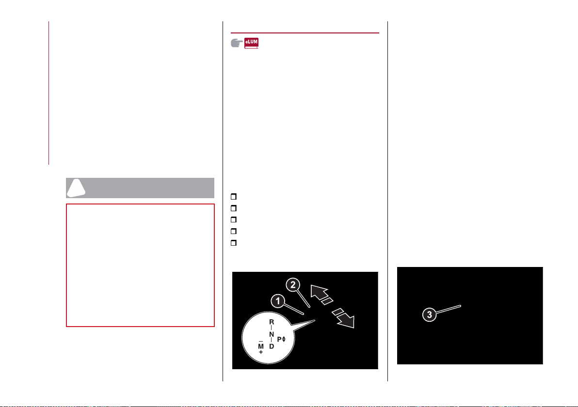
STARTING AND DRIVING
126
The electric parking brake engages
automatically to prevent vehicle
movement.
The Safe Hold function can be
temporarily disabled by pressing the
switch located on the central tunnel and
the brake pedal at the same time, with
the car stationary and the driver side
door open.
Once disabled, the function will activate
again when the vehicle speed reaches
18 mph (20 km/h) or the ignition device is
moved to STOP and then to ON.
WARNING
113) In the case of parking manoeuvres
on roads on a gradient, the front wheels
must be steered towards the pavement
(when parking downhill), or in the opposite
direction if the car is parked uphill. Block the
wheels with a wedge or a stone if the car is
parked on a steep slope.
114) Never leave children alone in an
unattended car; make sure that when you
move away from the car, you have the key
with you.
115) The electric parking brake must always
be engaged when leaving the car.
AUTOMATIC TRANSMISSION
The vehicle is equipped with an 8-speed
automatic transmission.
The transmission can operate in two
different modes: “Automatic” or
“Sequential”.
GEAR LEVER
116) 117) 118)
35) 36)
The transmission is operated by means
ofthe control lever (1) fig.109 which can
be used to select the following operating
modes:
P = Park
R = Reverse
N = Neutral
D = Drive, (automatic forward speed)
AutoStick: + shifting to higher gear
in sequential driving mode / - shifting to
lower gear in sequential driving mode.
109 07076V0686EM
The positions diagram is illustrated on
the top of the lever.
The letter corresponding to the selected
mode lights up and can be seen on the
instrument panel.
To select one of the operating modes,
move the lever forwards or backwards
and press the brake pedal at the same
time.
To engage R (Reverse) mode, press
thepedaland thebutton(3)fig.110 in
combination.
To pass from P (Park) mode directly to D
(Drive) mode, in addition to pressing the
brake pedal, it is also necessary to press
button (3).
To pass from R (Reverse) mode directly
to D (Drive) mode and vice versa, in
addition to pressing the brake pedal, it is
necessary to press button (3).
The P (Park) mode can be enabled
pressing the P (Park)(2) fig.109 button.
110 07076V0020EM
127
It is not possible to select N (Neutral)
mode from P (Park) mode.
P (Park) mode is automatically activated
if the following conditions are met
simultaneously:
D (Drive) or R (Reverse) operating
mode is active;
the vehicle speed is below 0 km/h (or
0 mph);
the brake pedal is released;
the driver’s seat belt is not fastened;
the driver’s door is open.
If using the gear shift in "sequential"
mode. you can activate it by moving the
lever from D (Drive) to the left and then
forward towards the - symbol or back
towards the + symbol and the gear is
shifted.
To exit position P (Park), or to pass
from position N (Neutral) to position D
(Drive) or R (Reverse) when the vehicle is
stopped or is moving at a low speed, the
brake pedal must also be pressed.
WARNING DO NOT accelerate while
shifting from position P (or N) to another
position.
WARNING After selecting a gear, wait
a few seconds before accelerating. This
precaution is particularly important with
a cold engine.
AutoStick - Manual (sequential)
shifting mode
In the case of frequent gearshifting (e.g.
for sport driving, when the vehicle is
driven with a heavy load, on slopes, with
strong headwind or when towing heavy
trailers), it is recommended to use the
Autostick (sequential shifting) mode to
select and keep a lower fixed ratio.
In these conditions, the use of a lower
gear improves vehicle performance,
preventing overheating.
It is possible to shift from D mode (Drive)
to sequential mode regardless of vehicle
speed.
Activation
Starting from D (Drive) mode, to activate
the sequential drive mode, move the
lever to the left (– and + indication of the
panel). The gear engaged will be shown
on the instrument panel display.
Gearshifting is made by moving the gear
lever forwards, towards symbol – or
backwards, towards symbol +.
Steering wheel stalks
(where provided)
The gear can be manually shifted also
by using the levers behind the steering
wheel, pull the right gear lever (+)
towards the steering wheel and release
it to engage a higher gear; perform the
same operation with the left lever (–) to
engagea lower gear fig.111.
To engage N (Neutral): pull
simultaneously both levers.
To activate D (Drive) mode, from N
(Neutral), P (Parking) and R (Reverse):
push the brake pedal and the right lever
(+).
111 07076V0021EM
WARNING If only one manual shift is
necessary, the letter D will remain on the
display of the instrument panel with the
engaged gear next to it.
Deactivation
To deactivate the sequential driving
mode, bring the gear lever back in
position D (Drive) ("Automatic" driving
mode).
TRANSMISSION EMERGENCY
FUNCTION
(where provided)
Transmission operation is constantly
monitored to detect any fault. If
STARTING AND DRIVING
128
a condition that might damage
the transmission is detected, the
"transmission emergency" function is
activated.
In this condition, the transmission stays
in 4th gear, regardless of the gear
selected. The P (Park), R (Reverse) and N
(Neutral) modes continue to work.
The symbol might light up on the
instrument panel display.
In the event of a "transmission
emergency" immediately contact the
nearest Alfa Romeo Dealership.
Temporary failure
If the symbol lights up, the failure may
be temporary, in which case, proceed as
follows to restore correct transmission
operation:
stop the car;
engage P (Park) mode;
bring the ignition device to STOP;
wait for about 10 seconds, then restart
the engine;
select the desired gear: if the
problem is not detected any more
the transmission correct operation is
restored.
WARNING In the event of a temporary
failure it is in any case recommended
to contact an Alfa Romeo Dealership as
soon as possible.
GEAR ENGAGEMENT DISABLING
SYSTEM WITHOUT BRAKE PEDAL
PRESSED
This system prevents you from moving
the gear lever from P (Park) mode if the
brake pedal has not been previously
depressed.
To bring the gear lever to a position other
than P (Park), the ignition device must be
in position AVV (engine on or off) and the
brake pedal must be pressed.
WARNING
116) Never use position P (Park) instead of
the electric parking brake. Always engage
the electric parking brake when parking the
vehicle to avoid the acciental movement of
the vehicle.
117) If the P (Park) position is not engaged,
the car could move and injure people. Before
leaving the car, make sure that the gear
lever is in position P and that the electric
parking brake is engaged.
118) Do not shift the gear lever to N
(Neutral) and do not stop the engine when
driving on a downhill road. This type of
driving is dangerous and reduces the
possibility of intervening in the case of
variation of the road traffic or surface. You
risk losing control of your car and causing
accidents.
IMPORTANT
35) Before selecting P (Park) mode, bring
the ignition device to position ON and press
the brake pedal. Otherwise, the gear lever
may get damaged.
36) Engage reverse only with the car
stationary, engine at idling speed and
accelerator fully released.
"ALFA DNA™" SYSTEM
DESCRIPTION
This device allows, using the selector
fig. 112 (onthecentral tunnel), different
car response modes to be selected
according to driving style and road
conditions:
d = Dynamic (sports driving mode)
n = Normal (mode for driving in normal
conditions)
a = Advanced Efficiency (ECO driving
mode for maximum fuel savings)
RACE = track race driving mode (where
provided)
= adjusts the calibration of the
suspensions (where provided)
On some versions when the engine is
stopped, the selector always returns to
"n" (Normal) mode.
129
112 04026V0997EM
Coasting function
(2.0 T4 MAir versions only)
The vehicle is equipped with a coasting
function, which allows you to save fuel.
The function is automatically activated
by the driver when the accelerator is
released below a certain vehicle speed,
without simultaneously pressing the
brake pedal.
The coasting function is active when the
accelerator pedal is released only if the
speed is below 150 km/h.
In this condition, the engine returns to
its idle state and the car decelerates
without the engine applying resistance
to the wheels. The engine is reconnected
to the transmission system the next time
the accelerator pedal is pressed.
DRIVING MODES
"Normal" Mode
On/off
It is activated by rotating the selector to
the letter "n", the displays light up in blue.
To deactivate the Normal mode, move
the selector to another mode ("d" or "a").
"Dynamic" Mode
On/off
It is activated by rotating the selector to
the letter "d", the displays light up in red.
To deactivate the Dynamic mode, move
the selector to "n", Normal mode.
"Advanced Efficiency" Mode
On/off
It is activated by rotating the selector
to the letter "a", the displays light up in
green.
To deactivate the Advanced Efficiency
mode, move the selector to "n", Normal
mode.
WARNING The selector will always be
positioned in Normal “n” mode when the
engine is started.
START & STOP EVO
The Stop/Start Evo automatically stops
the engine each time the car is stationary
and starts it again when the driver wants
to move off.
In this way, the vehicle efficiency is
increased, by reducing consumption,
dangerous gas emissions and sound
pollution.
OPERATING MODE
Stopping the engine
With car at a standstill and brake pedal
pressed, the engine switches off if the
gear lever is in a position other than R.
The system does not operate when the
gear lever is in R, for making parking
manoeuvres easier.
In the event of stops uphill, engine
switching off is disabled to make the "Hill
Start Assist" function available (works
only with running engine).
NOTE The engine can only be
automatically stopped after having run
at about 6.2 mph (10 km/h).
After an automatic restart, to stop the
engine you only need to move the car
(exceed a speed of 0.3 mph - 0.5 km/h).
Engine stopping is signalled by the
symbol lighting up on the instrument
panel display.
STARTING AND DRIVING
130
Restarting the engine
To restart the engine, release the brake
pedal or, for versions/markets where
provided, turn the steering wheel slightly.
With the brake pressed and the
transmission in automatic mode D
(Drive), the engine will restart by shifting
to R (Reverse), for petrol engine versions
only, to "AutoStick".
With brake pressed, also for versions
with petrol engines, if the gear lever is
in "AutoStick" mode, the engine can be
restarted by moving the lever to + or -.
SYSTEM MANUAL ACTIVATION /
DEACTIVATION
119)
37)
To manually activate/deactivate the
system, press the button inserted in the
control panel on the left of the steering
wheel, fig. 113.
113 07126V0001EM
LED off: system activated;
LED on: system deactivated;
SAFETY FUNCTIONS
When the engine is stopped through the
Start&Stop Evo system, if the driver
releases their seat belt, opens the
driver's or passenger's door or releases
the engine bonnet from inside the car,
the engine can be restarted only by using
the ignition device.
This condition is indicated to the driver
both through a buzzer and a message on
the instrument panel display.
WARNING
119) When replacing the battery, always
contact an Alfa Romeo Dealership. Replace
the battery with a new one of the same type
(HEAVYDUTY) and specifications.
IMPORTANT
37) If climate comfort is to be favoured, the
Start&Stop system can be deactivated,
for a continuous operation of the climate
control system.
SPEED LIMITER
DESCRIPTION
This device allows the speed of the car to
be limited to values which can be set by
the driver.
The maximum speed can be set both with
vehicle stationary and in motion. The
minimum speed that can be set is 20 mph
(30 km(h).
When the device is active, the vehicle
speed depends on the pressure at the
accelerator pedal, until the set speed
limit is reached.
ACTIVATING THE DEVICE
The function can be
activated/deactivated on the Connect
system.
Activating the device
To access the function, select the "Driver
Assistance" widget on the Connect
system display and select the "Comfort"
menu.
The activation of the device is signalled
by the displaying of the green symbol
along with the last speed set.
SPEED LIMIT PROGRAMMING
To access the function, on the main menu
select the following items in sequence:
"Settings", "Safety" and "Speed Limiter -
Set Speed".
131
By turning the Rotary Pad, the speed
increases by 5 mph (5 km/h), on rotation,
from a minimum of 20 mph (30 km/h) to a
maximum of 110 mph (180 km/h).
DEACTIVATING THE DEVICE
Deactivating the device
To access the function, on the main menu
select the following items in sequence:
"Settings", "Safety", “Speed Limiter” and
“Off”.
Automatic off of the device
The device deactivates automatically in
the event of fault in the system. In this
case, contact an Alfa Romeo Dealership.
CRUISE CONTROL
This is an electronically controlled
driving assistance device that allows the
desired car speed to be maintained,
without having to press the accelerator
pedal. This device can be used AI
speed above 20 mph (30 km/h) on long
stretches of dry, straight roads with few
variations (e.g. motorways).
It is therefore not recommended to use
this device on extra-urban roads with
traffic. Do not use the device in town.
Travelling downhill, the system could
brake the car to keep the set speed
unvaried.
ACTIVATING THE DEVICE
120) 121) 122)
To activate the device press button
fig. 114.
The white symbol on the instrument
panel display switches on to signal that
the device is on.
The Cruise Control function can remain
active concurrently with the Speed
Limiter system. If a speed limit below
the one indicated in the Cruise Control is
selected, the Cruise Control speed will be
lowered to that of the Speed Limiter.
The device cannot be engaged in 1
st
or
reverse gear: it is advisable to engage it
in 3
rd
gear or higher.
WARNING It is dangerous to leave the
device on when it is not used. There
is a risk of inadvertently activating it
and losing control of the car due to
unexpected excessive speed.
SETTING THE DESIRED SPEED
Proceed as follows:
activate the device;
when the car has reached the desired
speed,raise/lower theSETleverfig.114
and release it to activate the device.
When the accelerator is released, the
car will maintain the selected speed
automatically.
If needed (when overtaking for instance),
you can accelerate simply by pressing
the accelerator; when you release the
pedal, the vehicle goes back to the speed
stored previously.
When travelling downhill with the device
active, the car speed may slightly exceed
the stored one.
WARNING Before raising/lowering the
SET lever, the car must be travelling at a
constant speed on a flat surface.
INCREASING / DECREASING SPEED
112 07146V0030EM
Accelerating when overtaking
Depress the accelerator pedal: when this
is released the car will gradually go back
to the stored speed.
WARNING The device keeps the speed
stored even uphill and downhill. A slight
variation in the speed on slight rises is
completely normal.
STARTING AND DRIVING
132
RECALLING THE SPEED
With automatic transmission operating
in D mode (Drive - automatic), press and
release the RES fig. 112 button to recall
the previously set speed.
With an automatic transmission in
Autostick (sequential) mode, before
recalling the previously set speed you
should accelerate to get close to it, then
press and release the RES button.
DEACTIVATING THE DEVICE
Lightly pressing the brake pedal
deactivates the Cruise Control without
deleting the stored speed.
The Cruise Control may be deactivated
also by applying the electric parking
brake or when the braking system is
operated (e.g. operation of the ESC
system).
The stored speed is deleted in the
following cases:
pressing the on/off button or stopping
the engine;
if there is a malfunction in the Cruise
Control.
DEACTIVATING THE DEVICE
The Cruise Control is deactivated by
pressing the dated system on/off button
or by putting the starter switch in the
STOP position.
WARNING
120) While driving with the device active,
never move the gear lever to neutral.
121) In case of a malfunction or failure of the
device, contact an Alfa Romeo Dealership.
122) The Cruise Control can be dangerous if
the system cannot keep a constant speed. In
specific conditions speed may be excessive,
resulting in the risk of losing control of the
car and causing accidents. Do not use the
device in heavy traffic or on winding, icy,
snowy or slippery roads.
ACTIVE CRUISE CONTROL
(where provided)
123) 124) 125) 126) 127) 128) 129)
38) 39) 40) 41) 42) 43) 44)
The Active Cruise Control (ACC) is a
driver assist device which combines the
Cruise Control functions with one for
controlling the distance from the vehicle
ahead.
The device allows to hold the vehicle at
the desired speed without needing to
press the accelerator. It also allows to
hold a given distance from the vehicle
ahead (the distance can be set by the
driver).
The Active Cruise Control (ACC) uses a
radar sensor, located behind the front
bumper fig.115 and a camera, located
in the middle area of the windscreen
fig.116,todetectthepresenceofa
vehicle close ahead.
115 06016V0003EM
133
116 06016V0004EM
117 07146V0050EM
Important notes
If the sensor does not detect any vehicle
ahead, the device will maintain a fixed
set speed.
If the sensor detects a vehicle ahead,
the device automatically intervenes by
braking (or accelerating) slightly in order
not to exceed the original set speed, so
that the car keeps the preset distance,
seeking to adapt to the speed of the
vehicle ahead.
In the cases described below, the system
performance is not guaranteed, it is
therefore advisable to turn the device on
by pressing the / CANCfig. 117 button:
driving in fog, heavy rain, snow, heavy
traffic and in complex driving situations
(e.g. on motorways with roadworks in
progress);
driving near a bend (winding roads),
icy, snowy, slippery roads or with steep
slopes and descents;
entering a turn lane or on a slip road;
towing a trailer;
when circumstances do not allow safe
driving at a constant speed.
ACTIVATION / DEACTIVATION
The device may have four operating
states:
Enabled (speed not programmed);
Activated (speed programmed);
Pausing;
Deactivated.
Enabling / Activation
To turn on the device, press and release
the / CANCfig. 117 button.
With the device enabled and ready for
operation, the display on the instrument
panel shows the white icon with dashes
fig. 116 in place of the speed.
116 05036S0182EM
Setting a speed activates the system.
The instrument panel displays shows the
green icon fig.118 withthe set speed.
The device cannot be enabled when
RACE mode is active.
Pausing / Deactivating
With the device enabled (speed not set),
press the / CANC button.
Press the / CANC button again to
deactivate the device completely.
SETTING THE DESIRED SPEED
Speeds from 30 km/h (or 19 mph if
the unit set by the driver is "mph") to
180 km/h (or 110 mph if the unit set by the
driver is "mph") can be set.
when the car reaches the desired speed,
raise/lowerthe RES/SET leverfig.119
and release it to activate the device.
When the accelerator is released, the
car will maintain the selected speed
automatically.

STARTING AND DRIVING
134
119 07146V0051EM
Holding the accelerator pressed the
device will not be able to control the
distance between the vehicle and the
one ahead. In this case the speed will be
determined only by the position of the
accelerator pedal.
The device will return to normal
operation as soon as the accelerator
pedal is released.
The system cannot be activated:
when pressing the brake pedal;
when the brakes are overheated;
when the electric parking brake is
engaged;
when it is in P (Park), R (reverse) or N
(neutral) mode;
when the engine speed is above a
maximum threshold;
when the car speed is not within the
settable speed range;
when the ESC (or ABS or other
stability control systems) are operating
or have just operated;
when the ESC system is off;
during automatic braking by the
Forward Collision Warning system
(where provided);
in the event of device failure;
when the engine is off;
in case of obstruction of the radar
sensor (in this case the bumper area
where it is located must be cleaned).
In case of system set, the conditions
described above also cause a
cancellation or deactivation of the
system with times that may vary
according to the conditions.
WARNING The device does not
deactivate on reaching speeds higher
than those that can be set (180 km/h
or 110 mph if the unit set by the driver
is "mph") with the accelerator pedal
pressed. In these conditions, the device
may not work correctly and it is advisable
to deactivate it.
CHANGING THE SPEED
Increasing speed
Once the device has been activated,
it is possible to increase the speed by
lifting the RES/SET lever. Each time it is
operated, the speed increases by 1 mph
(1 km/h).
By moving the RES/SET lever beyond the
first resistance point, the set speed will
increase in steps of 6 mph (10 km/h) until
it is released, then the new speed will be
stored.
Decreasing speed
Once the device has been activated, it
is possible to decrease the speed by
lowering the RES/SET lever. Each time
it is operated, the speed decreases by
1 mph (1 km/h).
By moving the RES/SET lever beyond
the first resistance point, the set speed
will decrease in steps of 6 mph (10 km/h)
until it is released, then the new speed
will be stored.
Important notes
By keeping the accelerator pedal
depressed, the car can continue to
accelerate beyond the set speed. In this
case, lower the RES/SET lever to set the
speed to the current car speed.
When using the RES/SET lever to reduce
the speed, the braking system intervenes
automatically within the limits of the
system if engine braking does not slow
the car down sufficiently to reach the set
speed. The device holds the set speed
uphill and downhill; however a slight
variation is entirely normal, particularly
on slight gradients.
The automatic transmission could
change to a lower gears when driving
135
downhill or when accelerating. This is
normal and necessary to maintain the set
speed.
The device is switched off while driving if
the brakes overheat.
ACCELERATING WHEN OVERTAKING
130)
When driving behind a vehicle with the
device active, the device provides
additional acceleration to facilitate
overtaking if travelling at over 43 mph
(70 km/h) and the left direction indicator
(or the right indicator for right-hand drive
versions) is switched on.
In left-hand traffic, the overtaking assist
function is only active when the left-hand
lane is used for overtaking the vehicle
ahead (the opposite activation logic is
used in right-hand traffic countries).
RECALLING THE SPEED
Once the system has been cancelled
but not deactivated, and a speed was
previously set, simply move the RES/SET
lever up and lift your foot off the
accelerator to recall it.
The system will be set to the last stored
speed.
WARNING The recall function must only
be used if the road and traffic conditions
so allow. Recalling an excessively high or
low speed for the current traffic and road
conditions could cause an acceleration
or a deceleration of the vehicle. Failure
to comply with these precautions may
cause serious accidents and fatal
injuries.
SETTING THE DISTANCE BETWEEN
CARS
131) 132) 133) 134)
The distance between your car and the
vehicle ahead may be set to 1 bar (short),
2 bars (medium), 3 bars (long), 4 bars
(maximum) fig. 120.
120 07146S0079EM
The distances from the vehicle ahead are
proportional to speed.
The setting is 4 (maximum) the first time
the device is used. After the distance
has been modified by the driver, the new
distance will be stored also after the
system is deactivated and reactivated.
To decrease the distance
Press and release the button to decrease
the distancesetting fig. 121.The distance
setting decreases by one bar (shorter)
every time the button is pressed.
121 07146V0052EM
The set speed is held if there are no cars
ahead. Once the shortest distance has
been reached, a further press of the
button will set the longest distance.
The car holds the set distance until:
the vehicle ahead accelerates to a
speed higher than the set speed;
the vehicle ahead leaves the lane or
the detection field of the Active Cruise
Control sensor;
the distance setting is changed;
Active Cruise Control is
deactivated/paused.
DEACTIVATION
The device is deactivated and the set
speed is cancelled if:
the / CANC button on the Active
Cruise Control is pressed (with the
device on or paused);
STARTING AND DRIVING
136
the starter switch is in the STOP
position;
RACE mode is activated.
The device is cancelled (the set speed
and distance are stored):
when the device is paused (see the
“Active Cruise Control Activation /
Deactivation” paragraph);
when the conditions shown in the
“Setting the desired speed” paragraph
occur.
PRECAUTIONS WHILE DRIVING
The device may not work correctly in
some driving conditions (see below): the
driver must control the car at all times.
Towing a trailer
Use of the device is not recommended
while towing a trailer.
Vehicle not aligned
The device may not detect a car
travelling on the same lane but which is
not aligned along the same direction of
travel or a car which is cutting in from a
side lane. Sufficient distance from the
vehicles ahead may not be guaranteed in
these cases.
The non-aligned vehicle can weave in
and out of the driving direction causing
the vehicle to brake or accelerate
unexpectedly.
Steering and curves
When cornering with the device set,
it could limit speed and acceleration
to guarantee vehicle stability even if
no vehicles are detected ahead. When
leaving the curve, the device resets the
previously set speed.
WARNING In case of narrow curves,
the performance of the device could
be limited. In this case, it is advisable
to deactivate the device. Moreover,
remember that the device only limits the
speed DURING a bend and not BEFORE
it, so always take great care.
Using the device on gradient
When driving on roads with variable
gradient, the device may not detect the
presence of a vehicle on the lane. Device
performance could be limited according
to speed, load, traffic conditions and
gradient steepness.
Lane change
The device may not detect the presence
of a vehicle until it is fully in your lane.
In this case, sufficient distance from
the vehicle which is changing lane may
not be guaranteed: it is advisable to pay
the utmost attention at all times and
be always ready to press the brakes if
needed.
Small cars
Some narrow cars (e.g. bicycles and
motorcycles) travelling near the outer
edges of the lane or which enter the lane
from kerbside are not detected until they
are fully in the lane.
Sufficient distance from the cars ahead
may not be guaranteed in these cases.
Stationary objects and vehicles
The device can detect stationary
vehicles from 2.5 to 40 mph (4 to
60 km/h). Pay the utmost attention at all
times and be always ready to press the
brakes if needed.
Objects and cars moving in opposite or
crosswise direction
The device cannot detect the presence
of objects or vehicles travelling
in opposite or at right-angles and
consequently will not be operated.
WARNING
123) Pay the utmost attention while driving
at all times and be always ready to press the
brakes if needed.
124) The system is an aid for the driver,
who must always pay full attention while
driving. The responsibility always rests
with the driver, who must take into account
the traffic conditions in order to drive in
complete safety. The driver must always
maintain a safe distance from the vehicle in
front.
125) The device is not activated in presence
of pedestrians, oncoming vehicles in the
opposite direction of travel or moving in
137
the crosswise direction and stationary
objects (e.g. a vehicle standing in a queue or
a broken down vehicle).
126) The device cannot take account of
road, traffic and weather conditions and
conditions of poor visibility (e.g. fog).
127) The device does not always fully
recognise complicated driving conditions
which could cause incorrect or non-existing
determination of the safe distance to be
held.
128) The device cannot apply the maximum
braking force: the car will not be stopped
completely.
129) It is dangerous to leave the device
on when it is not used. There is a risk of
inadvertently activating it and losing control
of the car due to unexpected excessive
speed.
130) The device detects the direction of
traffic automatically when the car passes
from left-hand traffic to right-hand traffic.
In this case, the overtaking assist function
is only active when the reference vehicle
is overtaken on the right. The additional
acceleration is activated when the driver
uses the right direction indicator. In this
condition, the device no longer provides
the overtaking assist function on the left-
hand side until it determines that the car has
returned to left-hand traffic conditions.
131) The maximum breaking applied by the
device is limited. The driver may apply the
brakes in all cases if needed.
132) If the device predicts that the level of
braking is not sufficient to maintain the set
distance, the word “BRAKE!” or a dedicated
message on the instrument panel display
warns the driver that the vehicle ahead
is too close. An acoustic warning is also
emitted. In this case, it is advisable to brake
immediately as necessary to hold a safe
distance from the vehicle ahead.
133) The driver is responsible for ensuring
that there are no pedestrians, other vehicles
or objectives along the direction of the
vehicle. Failure to comply with these
precautions may cause serious accidents
and injuries.
134) The driver is fully responsible for
holding a safe distance from the vehicle
ahead respecting the highway code in force
in the respective country.
IMPORTANT
38) The system may have limited operation
or not work at all in weather conditions such
as: heavy rain, hail, thick fog, heavy snow.
39) The section of the bumper area in front
the sensor or the radar sensor itself must
not be covered with stickers, auxiliary
headlights or any other object.
40) Operation can be adversely affected by
any structural change made to the car, such
as a modification to the front geometry,
tyre change, or a heavier load than the
standard load of the car.
41) Incorrect repairs made on the front
part of the car (e.g. bumper, chassis) may
alter the position of the radar sensor, and
adversely affect its operation. Go to an Alfa
Romeo Dealership for any operation of this
type.
42) Do not tamper with or carry out any
intervention on the radar sensor or on the
camera on the windscreen glass. In the
event of a sensor failure, contact an Alfa
Romeo Dealership.
43) Do not wash with high-pressure jets
in the bumper lower area: in particular do
not operate on the system's electrical
connector.
44) Be careful in the case of repairs and
new paintings in the area around the sensor
(panel covering the sensor on the left side
of the bumper). In the event of a frontal
collision the sensor may automatically
deactivate and display a warning to indicate
that the sensor needs to be repaired. Even
without a malfunction warning, deactivate
the system operation if you think that the
position of the radar sensor has changed
(e.g. due to low-speed frontal collision as
during parking manoeuvres). In these cases,
go to an Alfa Romeo Dealership to have the
radar sensor realigned or replaced.
STARTING AND DRIVING
138
HAS (Highway Assist) SYSTEM
(where provided)
135) 136) 137) 138) 139) 140)
This is a driving assistance system which
works only when driving on motorways,
up to a top speed of 90 mph (145 km/h),
when horizontal signs are detected.
The system uses information from the
front camera and radar to help you keep
the car in the middle of the lane and at a
constant speed.
The HAS system combines Active Cruise
Control (ACC) and lane centring logic to
control the trajectory of the car holding it
as close as possible in the middle of the
lane and also managing speed.
Once the HAS is activated, a dedicated
screen will appear on the display of the
instrument panel (see the following
pages).
OPERATION
The system works only if the driver
keeps both hands on the steering wheel.
If your hands are removed from the
steering wheel, the system alerts you of
the need to put your hands back on the
steering wheel (see following pages).
If the vehicle crosses the lane marking,
the steering wheel will vibrate and a
dedicated screen will appear on the
instrument panel display.
WARNING The HAS can take a few
seconds to activate once all conditions
are met. During this time, a grey
indication will appear on the display of
the instrument panel and the system will
be activated automatically as soon
as all conditions are met, without any
intervention by the driver.
122 07146V0990EM
The following conditions must be met
before the HAS turns on:
the HAS system must be switched on
by pressing the button fig. 120 on the
steering wheel;
it is necessary to drive on the
motorway;
the Active Cruise Control device (ACC)
must be on;
the right and left lane marking lines
must be visible and correctly detected by
the front camera;
the car must be driving at a speed from
0 to 90 mph (0 to 145 km/h);
no camera, radar or Connect system
anomaly must be present;
the road lane width must be between
8.5 ft and 13.7 ft (2.6 metres and
4.2 metres);
the direction indicators must not be
activated;
no anomaly related to the system must
be present.
Other operating limits:
if the speed of the ACC device can be
set to a higher value (top speed 110 mph
/ 180 km/h), the HAS is only available as
long as the vehicle speed is equal to or
less than 90 mph (145 km/h);
when the ACC device speed is reduced
and the vehicle speed is less than 90 mph
(145 km/h), the system will reactivate
automatically;
if the ACC speed is set 90 mph
(145 km/h and with the HAS active
the vehicle speed exceeds 90 mph
(145 km/h) due to a slope, the system will
deactivate automatically.
ACTIVATION / DEACTIVATION
To activate the system, press the
button on the left side of the steering
wheel fig.122.

139
To deactivate the system press the
button again.
Suspension conditions
Carry out one of the following
operations:
start steering manually;
press the brake pedal;
disable the ACC device;
activate the direction indicators;
press the ACC device distance setting
button for 2 seconds to activate the
Cruise Control;
put the shift lever in P (park), R
(reverse) or N (neutral).
When the cause for suspension ends,
to reactivate the HAS you need to
reactivate the ACC device (for operation
of the ACC device, see the "Active Cruise
Control" paragraph in this chapter).
Automatic deactivation
System operation is temporarily
cancelled in the following cases:
if there are too narrow bends;
when hands are taken off from the
steering wheel;
if the left or right direction indicator is
activated;
if the driver intentionally changes
lanes without switching on the direction
indicator on the corresponding side;
if the driver's seat belt is released;
if the gear is put into D (Drive);
if the "Active braking" function is
activated (see the description in the
"FCW (Forward Collision Warning)"
paragraph in this chapter;
if the car leaves the motorway;
if lane marks are not detected by the
camera;
if there are system anomalies;
if the ACC device is deactivated;
if the vehicle speed exceeds the top
speed limit of the system (top speed
90 mph / 145 km/h);
if the lateral accelerations exceed the
limits envisaged by the system.
WARNING When the HAS is paused, the
symbol on the display turns red and
then grey.
WARNING Hands on the steering wheel
are detected by a capacitive sensor
installed in it.
When the automatic suspension
conditions are over, the HAS will be
available again without requiring any
reactivation action by the driver.
INDICATIONS ON THE DISPLAY
The system status can always be
viewed through a dedicated area on the
instrument panel display.
The system status is indicated by the
colour of the symbol .
The HAS system uses the sensors on
the steering wheel rim to detect if the
driver's hands are placed on the steering
wheel.
If the driver's hands are not positioned
on the steering wheel, a series of
warnings will appear on the instrument
panel display to alert the driver that he
needs to reposition his hands on the
steering wheel. Acoustic signals will also
be emitted.
After a certain period of time, the HAS
system will be disabled if the driver
has not repositioned his hands on the
steering wheel.
When the system does not detect
hands on the steering wheel, it will warn
the driver by displaying a dedicated
screen at the centre of the instrument
panel display (see the description in the
following pages).
SYSTEM STATUS
Active system
The active and correctly functioning
system status is indicated by a dedicated
screen in the "Driver Assistance" menu
on the display of the instrument panel.
If you are in a different menu, a screen
will appear on the instrument panel
display, which will provide information on
the systemactivationstatus fig. 123.

STARTING AND DRIVING
140
If you remove your hands from the
steering wheel, the system will
deactivate automatically but after a
few seconds. The display will show
a sequence of dedicated screens
and beeps to warn you of the need to
reposition your hands on the steering
wheel (see below).
Active system (hands removed from
the steering wheel for a short time)
As soon as you remove your from the
steering wheel,thisscreenfig. 124
appears on the instrument panel display:
in this case, the system remains active.
124 07076V0719EM
If your do not put your hands back on
the steering wheel within a few seconds,
thisscreenfig.125 will appearonthe
instrument panel display.
125 07076V0702EM
Active system (hands removed from
the steering wheel for a long time)
If the driver has not yet returned his
or her hands to the steering wheel,
thisscreenfig.126 will appearonthe
instrument panel display.
126 07076V0701EM
An acoustic signal will sound also in this
case. If you do not put your hands back on
the steering wheel after an extended
period of time, a deactivation message
will appear on the instrument panel
display. The steering wheel control will
then be deactivated.
This display will remain active even when
the hands are removed from the steering
wheel.
Then the symbol on the display will
turn grey.
If the HAS is deactivated because your
hands are not on the steering wheel, the
ACC (Active Cruise Control) will also be
deactivated.
When the HAS is active, the LKA (Lane
Keeping Assist) / LDW (Lane Departure
Warning) systems (where applicable)
will be temporarily paused. When the
HAS is not active, the LKA (Lane Keeping
Assist) / LDW (Lane Departure Warning)
systems (where applicable), if activated
123 07076V0700EM
141
previously, remain available. For more
information on the LKA and LDW
systems, see the following pages in this
chapter.
SYSTEM AVAILABILITY
External factors and conditions may
affect the proper operation of the HAS.
The main ones are listed below:
narrow, winding and curvy streets;
poor visibility (due to heavy rain, snow,
fog, etc.);
front lights of incoming cars or direct
sunlight or shade;
damage or obstructions caused by
mud, ice, snow, etc.
bumper damaged or not aligned;
interference with other equipment
that causes electromagnetic waves;
presence of roadworks/road
construction sites;
if the indications given by the
navigation system (if any) of the Connect
system are not yet ready and/or if the
navigation system is recalculating the
route.
SYSTEM LIMITED OPERATION
The HAS may have limited or reduced
functionality when one of the following
conditions occurs:
The main ones are listed below:
lane marking lines are not clear or in
conditions of poor visibility (e.g. in heavy
rain, snow, fog, etc.);
either the camera or radar are
damaged, covered or obstructed (e.g. by
mud, ice, snow, etc.);
when driving in the hills or on roads
with narrow turns;
near motorway tollgates;
when the motorway entrance or exit is
more than 20 ft (6 metres) wide;
if the camera is exposed to dazzling
light (e.g. reflection or direct sunlight;
if the Navigation system information
is not available and/or is being
recalculated.
WARNING
135) Many unpredictable situations that can
affect the performance of the HAS system
may arise. The driver must be ready to react
immediately and take control of the car in
place of the HAS system.
136) If the car approaches a bend that is too
narrow with respect to the current speed,
the HAS system turns off. The driver must
therefore be ready to immediately regain
control of the car at any time. To avoid this
situation it is important that the car speed
set does not exceed the current road speed
limit and that the driver keeps his or her
hands on the steering wheel.
137) The HAS system uses a hands on
steering wheel detection sensor: the driver
must keep his hands on the steering wheel
at all times. If the hands are removed from
the steering wheel for a certain period of
time, the system disengages and the ACC is
paused.
138) When using the HAS system, hold the
steering wheel and take into consideration
the road conditions and the surrounding
traffic. The driver must therefore be ready
to immediately regain control of the car
at any time. Failure to observe these
instructions can cause severe injuries with
even lethal consequences.
139) The HAS system is an aid for the driver,
who must always pay full attention while
driving. The responsibility always rests
with the driver, who must take into account
the traffic conditions in order to drive in
complete safety. The driver must always
maintain a safe distance from the vehicle in
front.
140) If the windscreen must be replaced due
to scratches, chipping or breakage, contact
exclusively an Alfa Romeo Dealership. Do
not replace the windscreen on your own, risk
of malfunction! It is advisable to replace the
windscreen if it is damaged in the area of
the camera.
STARTING AND DRIVING
142
TJA (Traffic Jam Assist)
SYSTEM
(where provided)
141) 142) 143) 144) 145) 146) 147) 148)
It is a driving assistance system that can
be activated on all road types.
The system uses information from the
front camera and radar to help you keep
the car in the middle of the lane at a
constant speed.
The HAS combines Active Cruise Control
(ACC) functions and lane centring logic to
control the trajectory of the car holding it
as close as possible in the middle of the
lane and also managing speed.
WARNING Do not use the TJA system
while driving in urban traffic.
OPERATION
The system only works if the driver
keeps his or her hands on the steering
wheel.
If the system detects that hands have
been removed from the steering wheel,
it will alert you of the need to put your
hands back on the steering wheel (see
following pages).
WARNING If the vehicle is about to cross
the lane marking, the steering wheel
will vibrate and a dedicated screen will
appear on the instrument panel display.
WARNING The TJA can take a few
seconds to activate once all conditions
are met. During this time, a grey
indication will appear on the display of
the instrument panel and the system will
be activated automatically as soon
as all conditions are met, without any
intervention by the driver.
127 07146V0990EM
The following conditions must be met
before the TJA turns on:
the TJA must be switched on by
pressingthebuttonfig.127 on the
steering wheel;
the Active Cruise Control device (ACC)
must be on;
the car must be driving at a speed from
0 to 40 mph (0 to 60 km/h);
no camera, radar or Connect system
anomaly must be present;
the road lane width must be between
8.5 ft and 13.7 ft (2.6 metres and
4.2 metres);
the direction indicators must not be
activated;
no anomaly related to the system must
be present;
if the set speed is above 40 mph
(60 km/h), the TJA system will not
operate after the vehicle has exceeded i
60 km/h;
if the speed of the Active Cruise
Control (ACC) device can be set to a
higher value (top speed 180 km/h), the
TJA is only available as long as the
vehicle speed is lower than or equal to
40 mph (60 km/h);
ACTIVATION / DEACTIVATION
To activate the system press the button
located on the left side of the
steering wheel.
If the event that the lane marking line is
missing or not correctly recognised, the
TJA system may also use information
from adjacent and preceding vehicles.
This condition may occur in congested
traffic, when the car in front and/or
objects around the car obstruct the lane
markings. In this case, the system can use
the queues of cars in the traffic to define
the driving trajectory. Alternatively, at
speedsbelow 12 mph(20 km/h),the
system can use the "lock-on" strategy,
which allows it to automatically following
the car in front.

143
disable the ACC device;
if the vehicle speed exceeds the
top speed limit (top speed 40 mph /
60 km/h);
release the driver's seat belt;
put the shift lever in P (park), R
(reverse) or N (neutral);
if the Forward Collision Warning (FCW)
system or "Active braking" intervenes.
Automatic deactivation
System operation is temporarily paused
in the following cases:
if there are very tight bends;
if the lines are not detected correctly;
if the left or right direction indicator is
activated;
if the driver intentionally changes
lanes without switching on the direction
indicator on the corresponding side;
if manual steering starts;
if you take your hands off the steering
wheel;
when there is no surrounding traffic
and there are no horizontal markings or
they cannot be detected;
if there are system anomalies;
if the vehicle speed exceeds the
maximum limit;
if lateral acceleration is high.
WARNING When the TJA is paused, the
symbol on the display turns red and
then grey.
WARNING Hands on the steering wheel
are detected by a capacitive sensor
installed in it.
When the automatic suspension
conditions are over, the TJA will be
available again without requiring any
reactivation action by the driver.
INDICATIONS ON THE DISPLAY
The system status can always be
viewed through a dedicated area on the
instrument panel display.
The system status is indicated by the
colour of the symbol.
The TJA system uses the sensors on the
steering wheel to detect if the driver's
hands are on it.
If the driver's hands are not on the
steering wheel, a series of warnings
will appear on the instrument panel
display to alert the driver that he needs
to reposition his hands on the steering
wheel. Acoustic signals will also be
emitted.
After a certain period of time, the TJA
system will be disabled if the driver has
not repositioned his or her hands on the
steering wheel.
When the system does not detect hands
on the steering wheel for a few seconds,
it will warn the driver by displaying
a dedicated screen at the centre of
the instrument panel display (see the
description in the following pages).
SYSTEM STATUS
Active system
The active and correctly operating
system status is indicated by the
following screen on the instrument panel
displayfig.128 in the "DriverAssistance"
menu.
128 07076S0728EM
When the hands are removed from the
steering wheel, the system does not
deactivate automatically, but after a
few seconds: some dedicated screens
appear on the instrument panel display in
sequence, to warn the driver to return his
or her hands to the steering wheel (see
the description below).
one of the two lines is broken or ruined;
the sun is low and is dazzling the
camera on the windscreen;
To deactivate the system press the
button again.
Suspension conditions
Perform one of the following operations:
press the brake pedal;
open the driver's door;
STARTING AND DRIVING
144
appears on the instrument panel display:
129 07076S0725EM
If the driver has not returned his or her
hands to the steering wheel within a few
seconds,thisscreenfig.130 willappear
on the instrument panel display.
07076S0726EM
Active system (hands removed from
the steering wheel for a long time)
If the driver has not yet returned his
or her hands to the steering wheel,
thisscreenfig.131 will appear onthe
instrumentpanel display.
An acoustic signal will sound also in this
case. If you do not put your hands back
on the steering wheel after an extended
period of time, a deactivation message
will appear on the instrument panel.
The steering wheel control will then be
deactivated.
131 07076S0727EM
Then the
symbol on the display will
turn grey.
If the TJA system was deactivated
because your hands were not on the
steering wheel, the Active Cruise Control
(ACC) will also be deactivated and must
be reactivated.
When the TJA is active, the LKA (Lane
Keeping Assist) / LDW (Lane Departure
Warning) systems (where applicable)
will be temporarily paused. When the
TJA is not active, the LKA (Lane Keeping
Assist) / LDW (Lane Departure Warning)
systems (where applicable), if activated
previously, remain available. For more
information on the LKA and LDW
systems, see the following pages in this
chapter.
SYSTEM AVAILABILITY
External factors and conditions may
affect the proper operation of TJA.
The main ones are listed below:
narrow, winding and curvy streets;
poor visibility (due to heavy rain, snow,
fog, etc.);
front lights of incoming cars or direct
sunlight or shade;
damage or obstructions caused by
mud, ice, snow, etc.
bumper damaged or not aligned;
interference with other equipment
that causes electromagnetic waves;
presence of roadworks/road
construction sites;
if the indications given by the
navigation system (if any) of the Connect
system are not yet ready and/or if the
navigation system is recalculating the
route.
SYSTEM LIMITED OPERATION
The TJA may have limited or reduced
functionality when one of the following
conditions occurs:
The main ones are listed below:
lane marking lines are not clear or in
conditions of poor visibility (e.g. in heavy
rain, snow, fog, etc.);
130
Active system (hands removed from
the steering wheel for a short time)
As soon as you remove your from the
steering wheel,thisscreenfig. 129
145
either the camera or radar are
damaged, covered or obstructed (e.g. by
mud, ice, snow, etc.);
when driving in the hills or on roads
with narrow turns;
near motorway tollgates;
when the motorway entrance or exit is
more than 20 ft (6 metres) wide;
if the camera is exposed to dazzling
light (e.g. reflection or direct sunlight).
WARNING
141) Many unpredictable situations can
arise, affecting the performance of the TJA
system. The driver must be ready to react
immediately and take control of the car in
place of the TJA system.
142) If the car approaches a bend that is
too tight with respect to the current speed,
the TJA system turns off. The driver must
therefore be ready to immediately regain
control of the car at any time. To avoid this
situation it is important that the car speed
set does not exceed the current road speed
limit.
143) The TJA system uses a hands on
steering wheel detection sensor: the driver
must keep his hands on the steering wheel
at all times. If the hands are removed from
the steering wheel for a certain period of
time, the system disengages and the ACC
turns off.
144) When using the TJA system, hold
the steering wheel and consider the
road conditions and surrounding traffic.
The driver must therefore be ready to
immediately regain control of the car at any
time. Failure to observe these instructions
can cause severe injuries with even lethal
consequences.
145) The TJA system is an aid for the driver,
who must always pay full attention while
driving. The responsibility always rests
with the driver, who must take into account
the traffic conditions in order to drive in
complete safety. The driver must always
maintain a safe distance from the vehicle in
front.
146) If the windscreen must be replaced due
to scratches, chipping or breakage, contact
exclusively an Alfa Romeo Dealership. Do
not replace the windscreen on your own, risk
of malfunction! It is advisable to replace the
windscreen if it is damaged in the area of
the camera.
147) Driving the car on urban routes could
significantly change the sensitivity of the
system, due to the limited and/or lack
of vertical and horizontal signage and
variable traffic conditions. Therefore, it is
recommended not to use the TJA system
when driving in city streets.
148) Do not place any objects on the
steering wheel (e.g. steering wheel covers of
any type or material) which could interfere
with the capacitive hand detection sensor
on the steering wheel.
TSR (Traffic Sign Recognition)
SYSTEM
(where provided)
149) 150) 151)
45) 46) 47) 48) 49)
The system automatically detects the
recognizable road signs through a
camera located in the central area of the
windscreen:
speed limits;
no overtaking;
signs indicating the end of the
prohibitions indicated above.
If the camera does not detect valid speed
limits, the Connect system navigation
system may suggest unregulated speed
limits.
The system always checks the traffic
signs indicating the current speed limit
and possible no overtaking signs. The
system is able to recognize and show on
the instrument panel display, up to two
different road signs.
Depending on the unit of measurement
("km" or "mph") set through the
"Unit of measurement" menu on the
Connect system, the TSR system will
automatically show on the instrument
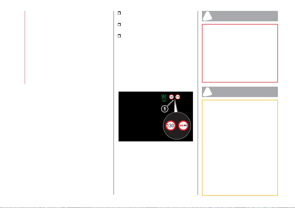
STARTING AND DRIVING
146
panel display the indication of the road
sign in the unit of measurement set.
TSR SYSTEM USE
System activation / deactivation
The system can be
activated/deactivated using the "Driver
Assistance" menu and then selecting
"Comfort" on the Connect system.
The system activation is signalled by
the road signs shown on the instrument
panel display.
Important notes
Selecting "Blinking" it is possible to
activate a warning when the effective car
speed exceeds that indicated by the TSR
system and displayed on the instrument
panel. In this case, the speed road sign on
the instrument panel display will blink
until the effective speed drops below
the displayed limit. Selecting "Offset",
it is possible to set the threshold at
which "Blinking" is activated, up to a
maximum of 6 mph (10 km/h) above the
limit detected by the system.
Indications on the display
The system status can always be
viewed through a dedicated area on the
instrument panel display.
This area contains the following road
sign information, from left to right within
the two dedicated zones:
the new speed limit recognised by the
system (1)fig.132;
the "road sign not detected" (---)
indication, where applicable;
the no overtaking sign.
If the camera does not detect valid
speed limits, the navigation system may
suggest unregulated speed limits on the
display.
The previously displayed sign is no longer
valid after a certain distance has been
travelled if the system does not detect
other road signs, and the limit given by
the navigation system maps is indicated.
132 07076V0777EM
If a trailer and its light connector are
connected to the car, the instrument
panel display will show the additional
trailer connected sign.
NOTE The TSR system will always be
active every time the engine is started.
WARNING
149) The system only detects preset traffic
signs if the minimum visibility conditions
and distance from the sign are met.
150) The system is an aid for driving and
does not relieve the driver of responsibility
for driving the car. Always respect the
highway code of the country you are driving
in.
151) When the system is active, the driver
is responsible for controlling the car and
monitoring the system, and must be ready
to intervene as appropriate if necessary.
IMPORTANT
45) Functionality may be limited or the
system may not work if the sensor is
obstructed.
46) The system may have limited operation
or not work at all in weather conditions,
such as heavy rain, hail, thick fog and low
temperatures. Strong light contrasts can
influence the recognition capability of the
sensor.
47) The area surrounding the sensor must
not be covered with stickers or any other
object.
48) Do not tamper or perform any
operations in the area of the windscreen
glass directly surrounding the sensor.
49) Clean the windscreen glass from
foreign matters such as bird droppings,
insects, snow or ice. Use specific detergents
and clean cloths to avoid scratching the
windscreen.
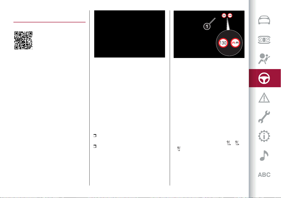
147
ISC (Intelligent Speed Control)
SYSTEM
(where provided)
You can decide whether to accept
or reject the proposal to adjust the
speed set by the ACC to match the
one suggested by the speed limit
symbol by using the RES/SET lever
locatedonthe steering wheel fig. 133. A
corresponding icon will be shown on the
instrument panel display (se description
in respective paragraph).
If the speed limit determined by reading
the road signs or by traffic conditions is
exceeded, the speed limit will flash on
the instrument panel.
133 07146V0022EM
ACTIVATION / DEACTIVATION
Activation
The system can be
activated/deactivated using the "Driver
Assistance" menu and then selecting
"Comfort" on the Connect system.
The system activation is signalled by
thesymbol 1 fig.134 lighting up onthe
instrument panel display.
Deactivation
The system is deactivated under the
following conditions:
when the Traffic Sign Recognition
system is deactivated;
when the Active Cruise Control device
is deactivated.
WARNING Selecting "Speed Offset" it is
possible to set the speed increment to
which the ISC system will adjust, up to a
maximum of 10 km/h above the speed
limit sign detected by the system, or
the speed decrement to which the ISC
system will adjust, down to a minimum
of 10 km/h below the speed limit sign
detected by the system. In these cases,
the road sign information shown on the
instrument panel display will remain that
detected by the TSR system.
INDICATIONS ON THE DISPLAY
The system status is always shown by a
dedicated white or green icon /
/ on the instrument panel display
(similar to that for the Active Cruise
Control device), to the left of the road
sign indications provided by the TSR
system.
134 07076V0777EM
The ISC system, where provided, is
combined with the ACC (Active Cruise
Control) system and TSR (Traffic Sign
Recognition) system and suggests an
automatic speed adjustment to the
driver based on the speed limit for the
road being travelled.
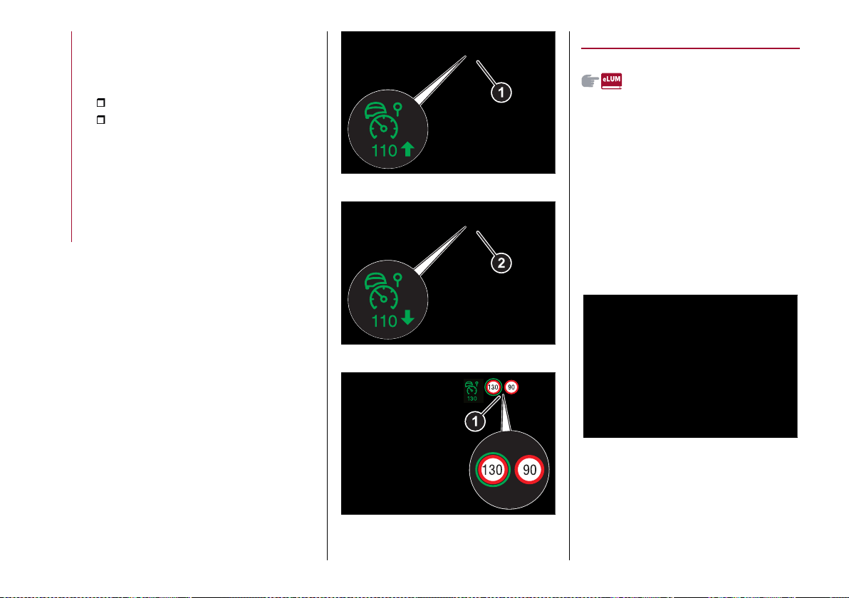
STARTING AND DRIVING
148
ACCEPTANCE / REJECTION OF THE
SUGGESTED SPEED
The system can be activated if the driver
has previously activated:
the Active Cruise Control device;
the Traffic Sign Recognition system.
When these systems are active, the
instrument panel display can show an
icon that indicates the suggested speed
(provided bythe TSR system) (1) fig.135
or(2)fig. 136, which the drivercan decide
to accept or reject using the RES/SET
lever on the steering wheel.
To accept the proposed speed and
consequently adjust the speed set by
the Active Cruise Control, move the
RES/SET lever in the direction of the
green arrow displayed next to the ISC
system icon.
Otherwise (moving the RES/SET lever
in the opposite direction to that of the
arrow on the display) the driver rejects
the proposed speed, and the Active
Cruise Control will continue to regulate
to the previously set speed.
If the driver accepts the value suggested
by the ISC or if the speed set using the
Active Cruise Control device is the same
as the that detected by the Traffic Sign
Recognition system, the speed limit sign
on the instrument panel display will be
highlightedwitha green circle(1) fig.137.
135 07076S0711EM
136 07076S0710EM
137 07076S0706EM
PARK SENSORS SYSTEM
(where provided)
152)
50) 51) 52)
VERSIONS WITH 4/8 SENSORS
The parking sensors, located in the rear
bumperfig.138 (versions with4 sensors)
or inthefrontand rearbumpersfig.139
(versions with 8 sensors), detect the
presence of any obstacles and warn the
driver about them, through an acoustic
warning and, where provided, visual
indications on the instrument panel
display.
138 07176V0001EM
149
139 07176V0003EM
Engagement/release
Versions with 4 sensors
To disengage the system press button
fig. 138. The LED located in the button
will light up or not when the system
switches from on to off (and vice versa):
LED off system on / LED on steady light
system off.
If the button is pressed with a system
failure, the LED flashes for about 5
seconds, then it stays on constantly.
Versions with 8 sensors
Front sensors: To turn off the front
sensors,pressbutton fig. 140.TheLED
located in the button will light up or not
when the sensors switch from on to off
and vice versa: LED off sensors on / LED
on steady light sensors off.
If the button is pressed with a system
failure, the LED flashes for about 5
seconds, then it stays on constantly.
Front and rear sensors: to
activate/deactivate the system (front
and rear sensors) use the "Settings"
menu of the Connect system.
140 07176V0002EM
When the ignition device is set to ON
the Park Sensors system keeps the
last state when the engine was stopped
(activated or deactivated) in its memory.
System activation/deactivation
When the reverse gear is engaged, the
system when engaged, activates the
front and rear sensors (where provided).
If a different gear is engaged, the rear
sensors are deactivated, while the front
sensors (where provided) remain active
up to 9.3 mph (15 km/h).
Operation with a trailer
The operation of the rear sensors is
automatically deactivated when the
trailer is plugged to the tow hook socket
of the car, while the front sensors (where
provided) stay active and can provide
acoustic and visual warnings.
The sensors are automatically
reactivated when the trailer's cable plug
is removed.
Important notes
Some conditions may influence the
performance of the parking system:
reduced sensor sensitivity and a
reduction in the parking assistance
system performance could be due to the
presence of: ice, snow, mud, thick paint,
on the surface of the sensor;
the sensor may detect a non-existent
obstacle ("echo interference") due to
mechanical interference, for example
when washing the vehicle, in rain (strong
wind), hail;
the signals sent by the sensor can also
be altered by the presence of ultrasonic
systems (e.g. pneumatic brake systems
of trucks or pneumatic drills) near the
vehicle;
parking assistance system
performance can also be influenced by
the position of the sensors, for example
due to a change in the ride setting
(caused by wear to the shock absorbers,
suspension), or by changing tyres,
overloading the vehicle or carrying out
specific tuning operations that require
the vehicle to be lowered;
STARTING AND DRIVING
150
the presence of a tow hook without
trailer, which may interfere with the
correct operation of the parking sensors.
Before using the Park Sensors system,
it is recommended to remove the tow
hook ball assembly when the vehicle is
not used for towing. Failure to comply
with this prescription may cause
personal injuries or damage to vehicles
or obstacles since, when the continuous
acoustic warning is emitted, the tow
hook ball is already in a position that is
much closer to the obstacle than the rear
bumper. If you wish to leave the tow
hook fitted without towing a trailer, it
is advisable to contact an Alfa Romeo
Dealership for the Park Sensors system
update operations because the tow hook
could be detected as an obstacle by the
central sensors.
the presence of adhesives on the
sensors. Therefore, take care not to
place stickers on the sensors.
WARNING
152) Parking and other potentially
dangerous manoeuvres are, however,
always the driver’s responsibility. When
performing these operations, always
make sure that there are no other people
(especially children) or animals on the route
you want to take. The parking sensors are
an aid for the driver, but the driver must
never allow their attention to lapse during
potentially dangerous manoeuvres, even
those executed at low speeds.
IMPORTANT
50) For correct operation of the system,
sensors must always be clean from mud,
dirt, snow or ice. Be careful not to scratch
or damage the sensors while cleaning them.
Avoid using dry, rough or hard cloths. The
sensors must be washed using clean water,
with the addition of vehicle shampoo if
necessary. When using special washing
equipment such as high pressure jets or
steam cleaning, clean the sensors very
quickly keeping the jet more than 10 cm
away.
51) Have interventions on the bumper in the
area of the sensors carried out only by an
Alfa Romeo Dealership. Interventions on the
bumper that are not carried out properly
may compromise the operation of the
parking sensors.
52) Only have the bumper repainted or any
retouches to the paintwork in the area of
the sensors carried out by an Alfa Romeo
Dealership. Incorrect paint application could
affect the operation of the parking sensors.
LANE DEPARTURE WARNING
(LDW) SYSTEM
DESCRIPTION
53) 54) 55) 56)
The Lane Departure Warning system
makes use of a camera located on the
windscreen to detect the lane limits,
calculate the position of the vehicle
within such limits and possibly indicate
departure to the driver.
When one or both lane limits are
detected and the vehicle passes over
one without the driver's say-so (direction
indicator not turned on), the system will
emit an acoustic signal.
If the vehicle continues to go beyond the
line of the lane without any intervention
from the driver, the surpassed line will
light up on the display (left or right)
fig. 141 tourgethe driverto bringthe
vehicle back into the limits of the lane.
141 07076V0703EM
(where provided)
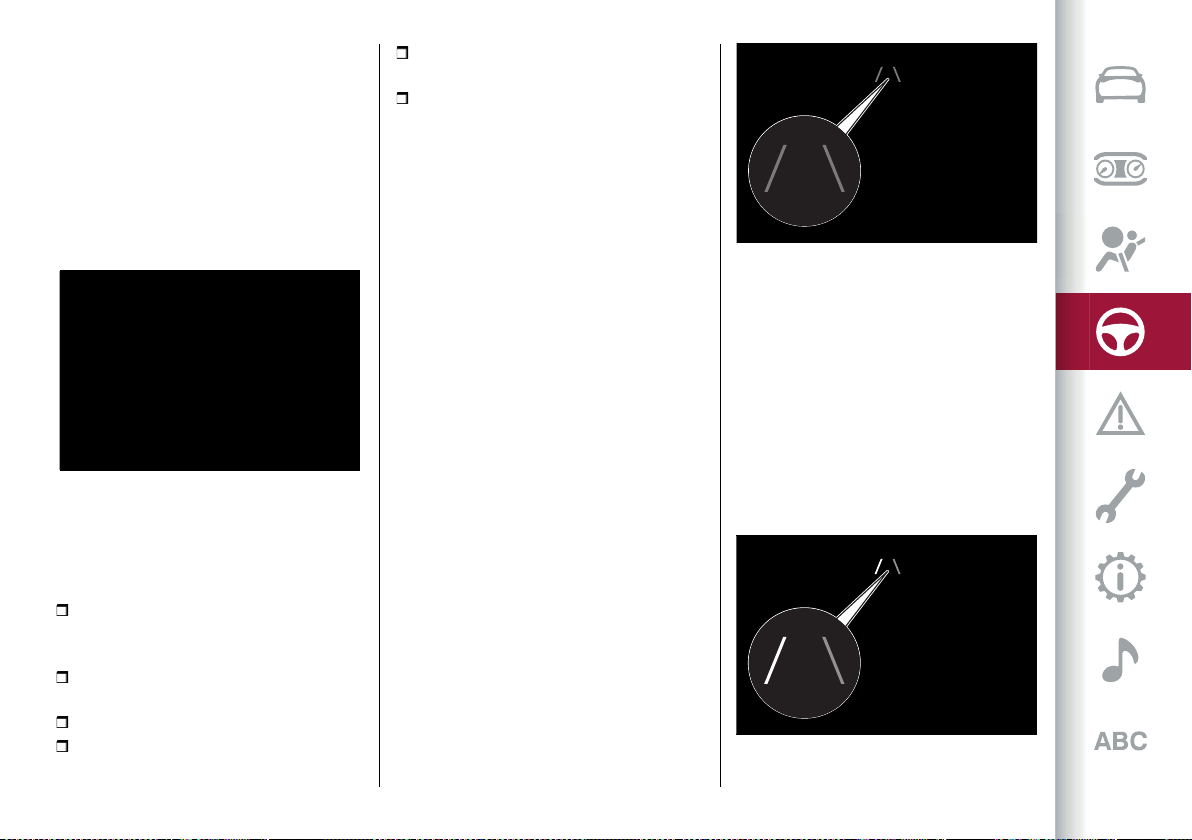
151
SYSTEM ON/OFF
The system can be turned on/off by
pressingthe fig.142 button orusing
the "Driver Assistance" menu and then
selecting "Safety " on the Connect
system.
Each time the engine is started, the
system maintains the operating mode
that was selected when it was previously
switched off.
142 07226S0001EM
Activation conditions
Once switched on, the system becomes
active only if the following conditions are
met:
the car speed is equal to or higher than
60 km/h (the system is deactivated at
speeds equal to or higher than 180 km/h);
the lane limit lines are visible at least
on one side;
there are suitable visibility conditions;
the road is straight or with wide radius
bends;
a suitable distance is kept from the
vehicle in front;
the direction indicator (for leaving the
lane) is not active.
SYMBOLS AND MESSAGES ON THE
DISPLAY
The Lane Departure Warning system also
advises the driver when the car changes
lane by showing symbols and messages
on the instrument panel display.
The message at the top of the display
remains active only until the main
reconfigurable area of the display is
activated (see the description in the
"Display" paragraph in the "Knowing the
instrument panel" section) pressing the
TRIP button located on the right lever of
the steering wheel.
Activating the main reconfigurable
area the messages related to the Lane
Departure Warning system will be shown
in this area.
When the system is active and the
lane limits have not been detected,
the display shows a specific grey icon,
fig. 143.
Exiting a lane with detection of a single
limit
When the system is active and only, for
example, the left lane limit has been
detected, the detected lane lights up in
white on the instrument panel display.
The system is ready to provide visual
warnings on the display in the event of
exiting the lane unintentionally (direction
indicator not activated) to the left,
fig. 144.
143 07226S0020EM
144 07226S0023EM
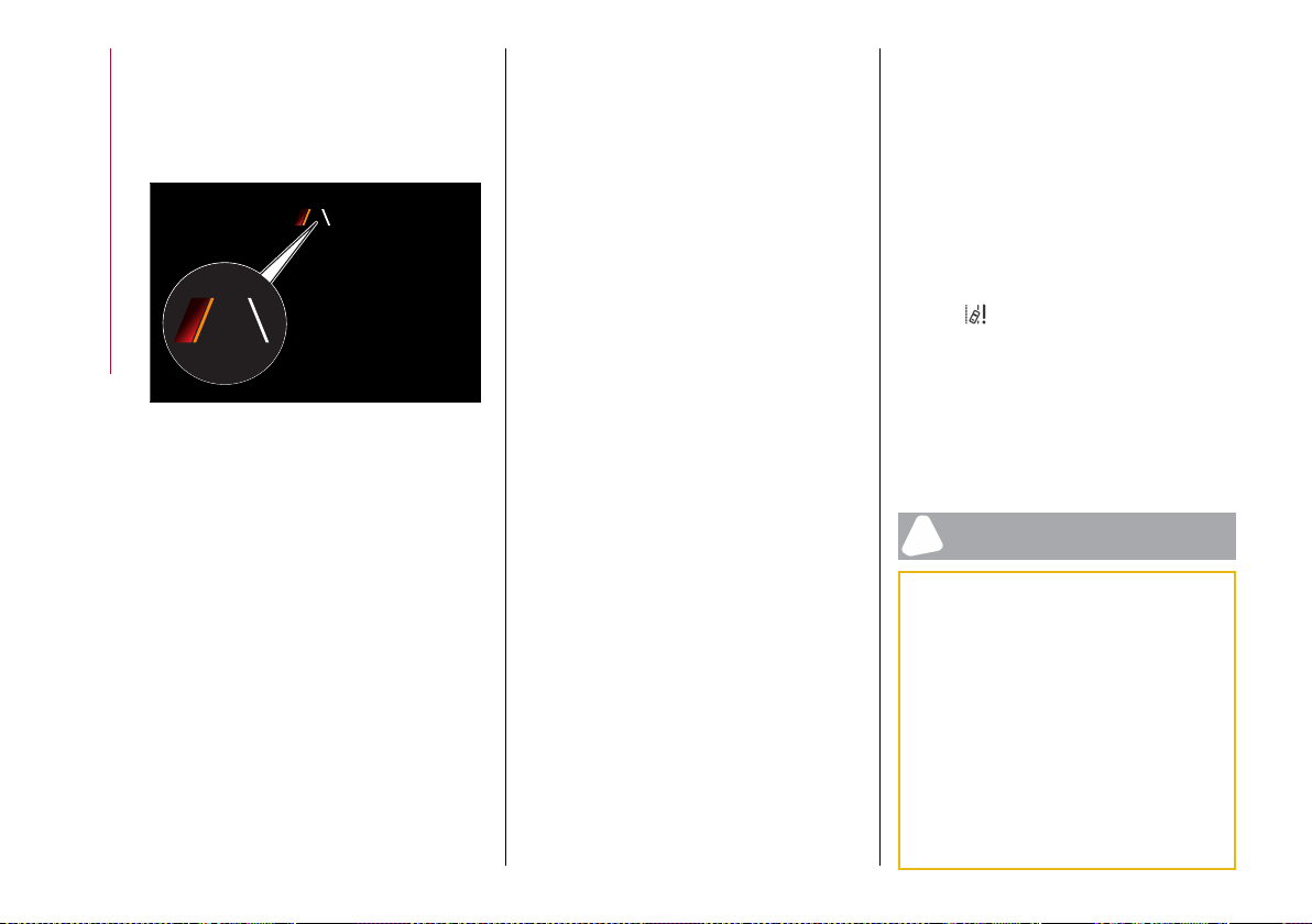
STARTING AND DRIVING
152
When the system detects that the car
has approached the lane line and is
about to overtake it, the left line on the
instrument panel display lights up yellow
and redfig. 145.
The system operates in the same way,
but mirrored, in the event of exiting the
right lane when only the right lane limit
has been detected.
Exiting a lane with detection of both
limits
When the system is active, the lane lines
on the display become white to indicate
the successful detection of the limits.
The system is ready to provide
indications in case of accident lane
departure (direction indicator not
activated).
In accordance with the different
conditions detected, the system can
attract the attention of the driver by
altering the lines that identify the lanes
on the instrument panel display. In
particular, the system can alter their
colour (from white to yellow and vice
versa).
If a lane line is crossed, this is indicated
on the display of the instrument panel by
means of a red flashing graphic symbol
and by an acoustic signal. The warning is
emitted from the loudspeakers on the
side of the lane limit being crossed (e.g. if
the vehicle is crossing the left line of the
lane, the acoustic warning will come from
the loudspeakers on the left).
Changing the system sensitivity
The system sensitivity intervention can
be adjusted using the "Driver Assistance"
menu and then selecting "Comfort" on
the Connect system.
The possible options are "High" or "Low".
System limited operation signal
57) 58)
If the dedicated message is shown on
the instrument panel display, a condition
limiting the system operation may have
occurred. The possible reasons of this
limitation are something blocking the
camera view or a fault.
If an obstruction is signalled, clean the
area of the windscreen by the interior
rear-view mirror.
Although the vehicle can still be driven
in normal conditions, the system may be
not completely available.
When the conditions limiting the system
functions end, this will go back to normal
and complete operation. Should the
fault persist, contact an Alfa Romeo
Dealership.
System failure signalling
If the system switches off and the
system appears on the instrument
panel display, it means that there is a
failure on the system.
In this case, it is still possible to drive the
vehicle, but you are advised to contact
an Alfa Romeo Dealership as soon as
possible.
IMPORTANT
53) Projecting loads on the roof of the car
may interfere with the correct operation of
the camera. Before starting make sure the
load is correctly positioned, in order not to
cover the camera operating range.
54) If the windscreen must be replaced due
to scratches, chipping or breakage, contact
exclusively an Alfa Romeo Dealership. Do
not replace the windscreen on your own, risk
of malfunction! It is advisable to replace the
windscreen if it is damaged in the area of
the camera.
55) Do not tamper with nor operate on the
camera. Do not close the openings in the
145 07226S0024EM
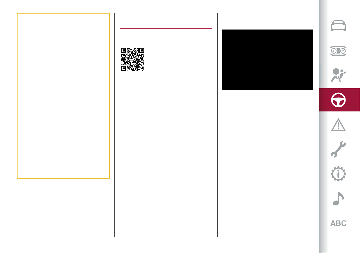
153
aesthetic cover located under the interior
rear-view mirror. In the event of a failure
of the camera, contact an Alfa Romeo
Dealership.
56) Do not cover the operating range of the
camera with stickers or other objects. Also
pay attention to other objects on the bonnet
(e.g. a layer of snow) and make sure they do
not interfere with the camera.
57) The camera may have limited or absent
operation due to weather conditions such
as: heavy rain, hail, thick fog, heavy snow,
formation of ice layers on the windscreen
glass.
58) Camera operation may also be
compromised by the presence of dust,
condensation, dirt or ice on the windscreen
glass, by traffic conditions (e.g. cars that
are driving not aligned with yours, car
driving in a transverse or opposite way on
the same lane, bend with a small radius of
curvature), by road surface conditions and
by driving conditions (e.g. off-road driving).
Make sure the windscreen is always clean.
Use specific detergents and clean cloths
to avoid scratching the windscreen. The
camera operation may also be limited or
absent in some driving, traffic and road
surface conditions.
LANE KEEPING ASSIST (LKA)
SYSTEM
DESCRIPTION
59) 60) 61) 62)
The Lane Keeping Assist system
makes use of a camera located on the
windscreen to detect the lane limits and
calculate the position of the car within
such limits, in order to make sure that it
remains inside the lane.
When one or both lane limits are
detected and the vehicle approaches one
of them without the driver signalling the
intention to to do so (direction indicator
not on), the system will apply a torque to
the steering wheel to keep the vehicle in
the lane and will generate a visual signal
(the left or right lane will turn yellow).
According to the type of signal set, it can
also emit an acoustic signal and/or apply
a vibration to the steering wheel.
If the vehicle continues to go beyond the
line of the lane without any intervention
by the driver, the surpassed line will light
up on the instrument panel display (the
left or right lane will turn yellow with red
shading)fig.146 tourgethe driver to
return the vehicle into the limits of the
lane.
SYSTEM ON/OFF
The system can be turned on/off by
pressingthe fig.147 buttonor using the
"Driver Assistance" menu on the Connect
system.
Each time the engine is started the
system maintains the operating mode
that was selected when it was previously
switched off.
The system is automatically switched off
when a trailer is coupled.
146 07076V0703EM
(where provided)
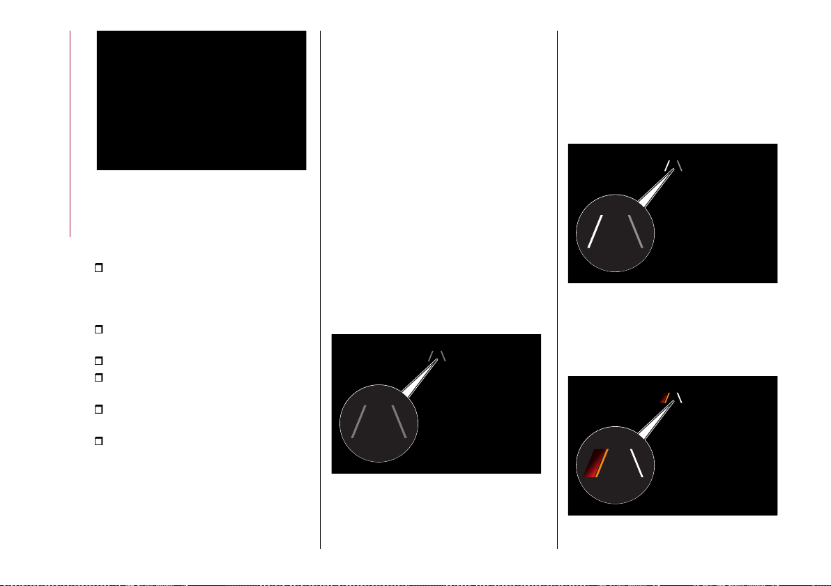
STARTING AND DRIVING
154
147 07226S0001EM
Activation conditions
Once switched on, the system becomes
active only if the following conditions are
met:
the car speed is equal to or higher
than 40 mph (60 km/h) (the system
is deactivated at speeds higher than
110 mph/ 180 km/h);
the lane limit lines are visible at least
on one side;
there are suitable visibility conditions;
the road is straight or with wide radius
bends;
a suitable distance is kept from the
vehicle in front;
the direction indicator (for leaving the
lane) is not active.
SYMBOLS AND MESSAGES ON THE
DISPLAY
The Lane Keeping Assist system also
advises the driver when the car changes
lane by showing symbols and messages
on the instrument panel display.
The message at the top of the
instrument panel display remains active
only until the main reconfigurable area
of the display is activated (see the
description in the "Display" paragraph
in the "Knowing the instrument panel"
section) pressing the TRIP button
located on the right lever of the steering
wheel.
Activating the main reconfigurable
area the messages related to the Lane
Keeping Assist system will be shown in
this area.
When the system is active and the
lane limits have not been detected,
the display shows a specific grey icon,
fig. 148.
Exiting a lane with detection of a single
limit
When the system is active and only, for
example, the left lane limit has been
detected, the detected lane lights up
in white on the display; the system is
ready to provide visual warnings on the
display in the event of unintentional
exiting of the lane (direction indicator
notactivated)totheleft, fig.149.
When the system detects that the car
has approached the lane line and is about
to pass it, the left line on the display
lightsupinyellow andredfig.150.
148 07226S0020EM
149 07226S0023EM
150 07226S0024EM

155
The system operates in the same way,
but mirrored, in the event of exiting the
right lane when only the right lane limit
has been detected.
Exiting a lane with detection of both
limits
When the system is active, the lane lines
on the display become white to indicate
the successful detection of the limits.
The system is ready to provide
indications in case it is accidentally
abandoned (direction indicator not
engaged).
In accordance with the different
conditions detected, the system can
attract the attention of the driver by
altering the lines that identify the lanes
on the instrument panel display. In
particular, the system can alter their
colour (from white to yellow and vice
versa).
If a line is crossed, it is also indicated
by an acoustic warning. The warning is
emitted from the loudspeakers on the
side of the lane limit being crossed (e.g. if
the vehicle is crossing the left line of the
lane, the acoustic warning will come from
the loudspeakers on the left).
Hands presence on the steering wheel
detection
The system is able to detect the
presence of the driver's hands on the
steering wheel.
if the driver has not yet returned his
or her hands to the steering wheel for
afew seconds, this screenfig.151 will
appear on the instrument panel display.
No acoustic warning will be emitted in
this case.
when the system does not detect
the presence of hands on the steering
wheel for a few seconds, a dedicated
screen will appear on the instrument
panel display. A short acoustic signal will
sound in this case.
If the driver continues not to return
his or her hands to the steering wheel,
thisscreenfig.152 will appearonthe
instrument panel display;
after maximum permissible time
with the hands removed from the
steering wheel, the LKA system will be
deactivated and a dedicated message
will be shown on the instrument panel
display. A continuous acoustic warning
will sound in this case.
In the last three cases listed above it is
necessary to reposition the hands on the
steering wheel.
Changing the system sensitivity
The system intervention sensitivity can
be adjusted using the "Driver Assistance"
menu on the Connect system.
The possible options are "High" or "Low".
Change of indications provided by the
system
The indications provided by the Lane
Keeping Assist system may be modified
using the Connect system.
Proceed as follows:
use the "Driver Assistance" menu;
151 07076V0716EM
152 07076V0718EM
STARTING AND DRIVING
156
select "Settings" and then select
"Warning type" or "Mode" and select one
of the required settings.
System limited operation signal
63) 64)
If the dedicated message is shown on
the instrument panel display, a condition
limiting the system operation may have
occurred. The possible reasons of this
limitation are something blocking the
camera view or a fault.
If an obstruction is signalled, clean the
area of the windscreen by the interior
rear-view mirror.
Although the vehicle can still be driven
in normal conditions, the system may be
not completely available.
When the conditions limiting the system
functions end, this will go back to normal
and complete operation. Should the
fault persist, contact an Alfa Romeo
Dealership.
System failure signalling
If the system switches off and the
system appears on the instrument
panel display, it means that there is a
failure on the system.
In this case, it is still possible to drive the
vehicle, but you are advised to contact
an Alfa Romeo Dealership as soon as
possible.
IMPORTANT
59) Projecting loads on the roof of the car
may interfere with the correct operation of
the camera. Before starting make sure the
load is correctly positioned, in order not to
cover the camera operating range.
60) If the windscreen must be replaced due
to scratches, chipping or breakage, contact
exclusively an Alfa Romeo Dealership. Do
not replace the windscreen on your own, risk
of malfunction! It is advisable to replace the
windscreen if it is damaged in the area of
the camera.
61) Do not tamper with nor operate on the
camera. Do not close the openings in the
aesthetic cover located under the interior
rear-view mirror. In the event of a failure
of the camera, contact an Alfa Romeo
Dealership.
62) Do not cover the operating range of the
camera with stickers or other objects. Also
pay attention to other objects on the bonnet
(e.g. a layer of snow) and make sure they do
not interfere with the camera.
63) The camera may have limited or absent
operation due to weather conditions such
as: heavy rain, hail, thick fog, heavy snow,
formation of ice layers on the windscreen
glass.
64) Camera operation may also be
compromised by the presence of dust,
condensation, dirt or ice on the windscreen
glass, by traffic conditions (e.g. cars that
are driving not aligned with yours, car
driving in a transverse or opposite way on
the same lane, bend with a small radius of
curvature), by road surface conditions and
by driving conditions (e.g. off-road driving).
Make sure the windscreen is always clean.
Use specific detergents and clean cloths
to avoid scratching the windscreen. The
camera operation may also be limited or
absent in some driving, traffic and road
surface conditions.
REAR BACK-UP CAMERA /
DYNAMIC GRIDLINES
DESCRIPTION
The Rear Back-up Camera is located on
the tailgate, near the opening button,
fig. 153.
153)
65)
153 07186V0001EM
Camera activation/deactivation
The function can be
activated/deactivated using the "Driver
Assistance" menu and then selecting
"Comfort" on the Connect system.
(where provided)
157
Activating the device
After activating the camera, it will be
possible to select one of the following
options:
"Activate"
"Switch-Off Delay"
"Camera Guidelines"
Select "Activate" to activate the camera
view on the Connect system display.
Whenever reverse gear is engaged, the
Connect systemdisplay, fig. 154, will
show the area around the car, as seen by
the Rear View Camera.
Controllare l'intera area circostante
154 07186V0060EM
SYMBOLS AND MESSAGES ON THE
DISPLAY
Activating the "Camera Guidelines"
shows the guidelines on the display.
If activated, the grid is positioned on
the image to highlight the width of the
vehicle and the expected reversing path
in accordance with the steering wheel
position.
A superimposed central broken line
indicates the centre of the vehicle to
facilitate parking manoeuvres or tow
hook alignment. The various coloured
areas indicate the distance from the rear
of the vehicle.
The table below shows the approximate
distancesfor eachareafig.154:
Area
Distance from the
rear of the
vehicle
Red 0 - 1 ft (0 – 30 cm)
Yellow
1 - 3.3 ft (30 cm - 1
m)
Green 3.3 ft (1 m) or more
WARNING When parking, take the
utmost care over obstacles that may be
above or under the operating range of
the camera.
WARNING
153) Parking and other potentially
dangerous manoeuvres are, however,
always the driver’s responsibility. While
carrying out these manoeuvres, always
make sure that no people (especially
children) or animals are in the area
concerned. The camera is an aid for the
driver, but the driver must never allow
his/her attention to lapse during potentially
dangerous manoeuvres, even those
executed at low speeds. Always keep a slow
speed, so as to promptly brake in the case of
obstacles.
IMPORTANT
65) It is vital, for correct operation, that
the camera is always kept clean and free
from any mud, dirt, snow or ice. Be careful
not to scratch or damage the camera while
cleaning it. Avoid using dry, rough or hard
cloths. The camera must be washed using
clean water, with the addition of vehicle
shampoo if necessary. In washing stations
which use steam or high-pressure jets, clean
the camera quickly, keeping the nozzle more
than 10 cm away from the sensors. Also, do
not apply stickers to the camera.
STARTING AND DRIVING
158
REFUELLING THE CAR
154) 155) 156)
Always stop the engine before refuelling.
PETROL ENGINES
Only use unleaded petrol with a number
of octanes (R.O.N.) not lower than 91
(EN228 specification).
DIESEL ENGINES
Only use Diesel for motor vehicles
(EN590 specification).
REFUELLING PROCEDURE
The fuel flap is unlocked when the central
door locking system is released, while it
is automatically locked when the central
locking system is applied.
Opening the flap
To refuel proceed as follows:
openflap(1)fig. 155, pressingonthe
point shown bythe arrow fig.156;
remove the closing cap (2);
return the cap to its seat (4);
introduce the dispenser in the filler
and refuel;
after refuelling, before removing the
dispenser, wait for at least 10 seconds in
order for the fuel to flow inside the tank;
then remove the dispenser from the
filler, close the cap and then close the
flap.
The refuelling procedure described
above is illustrated on the label (where
provided) located inside the fuel flap.
155 07226V0042EM
156 07206V0001EM
TOPPING UP AdBlue
®
DIESEL
EMISSIONS ADDITIVE
(2.2 JTD versions only)
157)
Preliminary conditions
AdBlue
®
freezes at temperatures lower
than 12.2 °F (-11 °C). If the car stands for
a long time at this temperature refilling
could be difficult. For this reason, it is
advised to park the car in a garage and/or
heated environment and wait for the
AdBlue
®
to return to liquid state before
topping up.
Proceed as follows:
park the car on level ground;
switch off the engine by turning the
ignition device to STOP;
openthefuelflap (1) fig.155 andthen
unscrew and remove the cap (3) (blue)
from the AdBlue
®
filler and put it in the
stowing position provided (4).
Refilling with nozzles
You can fill up at any AdBlue
®
distributor.
Proceed as follows:
insert the AdBlue
®
nozzle in the filler,
start refilling and stop refilling at the
first shut-off (the shut-off indicates that
the AdBlue
®
tank is full). Do not proceed
with the refilling, to prevent spillage of
AdBlue
®
;
extract the nozzle.
Refilling with containers
Proceed as follows:
check the expiration date;
read the advice for use on the label
before pouring the content of the bottle
into the AdBlue
®
tank;

159
if systems which cannot be screwed
in (e.g. tanks) are used for refilling, after
the indication appears on the instrument
panel display (see “Warning lights and
messages" paragraph in the “Knowing
the instrument panel” chapter), fill the
AdBlue
®
tank with no more than 1.1 UK
gal (5 litres);
if containers which can be screwed to
the filler are used, the reservoir is full
when the AdBlue
®
level in the container
stops pouring out. Do not proceed
further.
AdBlue
®
level display
The level of AdBlue
®
inside the tank can
be viewed on the Connect system display
fig. 157.
Proceed as follows:
activate the "Vehicle Information"
function pressing the appropriate widget
on the Connect system display.
press thegraphicbutton 1fig.157: the
level 2 of AdBlue
®
will appear on the
display.
If the AdBlue
®
level is not in reserve, the
message "OK" will appear on the display.
If the AdBlue
®
level is insufficient the
message "KO" will appear on the display.
Motor Oil
Tyr e
Next service in
Ad Blue
OK OK
OK
km
0
000
87
12:36
3600
76.
1°
72.
5
F
°
72.
5
F
°
months
out.
2
1
157 12126S0681EM
Operations after refilling
Proceed as follows:
fitthecap(3)fig.155 backon ‘the
AdBlue
®
filler by turning it clockwise and
screwing it completely;
set the ignition device to ON (it is not
necessary to start the engine);
wait for the indication on the
instrument panel to switch off before
moving the car. The indication may stay
on for a few seconds to approximately
half a minute. If the engine is started
and the car is moved, the indication
will remain on for longer. This will not
compromise engine operation;
if the AdBlue
®
was topped up
when the tank was empty, see the
“Refuelling ” paragraph in the “Technical
Specifications” chapter and wait for 2
minutes before starting the engine.
WARNING If AdBlue
®
is spilled out of
the filler neck, clean up well the area and
proceed to filling up again. If the liquid
crystallises, eliminate it with a sponge
and warm water.
IMPORTANT
DO NOT EXCEED THE MAXIMUM
LEVEL: this could cause damage to
the reservoir. AdBlue
®
freezes under
12.2 °F (-11 °C). Although the system is
designed to operate below the freezing
point of the AdBlue®, it is advisable not
to fill the tank beyond the maximum
level because if the AdBlue
®
freezes
the system can be damaged. Comply
with the instructions provided in this
section.
If the AdBlue
®
is spilled on painted
surfaces or aluminium, immediately
clean the area with water and use
absorbent material to collect the fluid
that has been spilled on the ground.
Do not try to start the engine if the
AdBlue
®
was accidentally added to
the Diesel fuel tank, this can result in
serious engine damage, contact a Alfa
Romeo Dealership.
Do not add additives or other fluids
to AdBlue
®
, doing so could damage the
system.
The use of non-conforming
or degraded AdBlue
®
may lead
to indications appearing on the
instrument panel display (see “Warning
lights and messages" paragraph in
STARTING AND DRIVING
160
the “Knowing the instrument panel”
chapter).
Never pour AdBlue
®
into another
container: it could be contaminated.
In case of damage to the sewage
system of exhaust gas resulting from
the use of additives / tap water, the
introduction of diesel fuel, or at least
by not fulfilling the requirements, the
warranty expires.
If the AdBlue
®
runs out, see
"Warning lights and messages"
paragraph in the "Knowing the
instrument panel” chapter to continue
using the car normally.
The AdBlue
®
level is not updated if
the car is parked on a sloping road.
The consumption of AdBlue
®
emissions additive depends on the
conditions of use of the car and is
indicated by means of the symbol and a
specific message on the instrument
panel display.
Fuels - identification of vehicle
compatibility. Graphic symbol for
consumer information in accordance
with EN16942
The symbols, shown below, make it
easier to recognise the correct fuel type
to use with your car.
Before refuelling, check the symbols
(where provided) inside the fuel
filler flap and compare them with the
symbols shown on the fuel pump (where
provided).
PETROL ENGINES
Inside the flap there is also the fuel type
(UNLEADED FUEL = petrol) and the
symbol (where provided) that certifies
compliance with the EN228 (petrol)
standardfig.158.
158 07206V0002EM
Symbols for petrol powered cars
E5: unleaded petrol containing up to 2.7%
(m/m) oxygen and with maximum 5.0%
(V/V) ethanol compliant with the EN228
specification.
E10: unleaded petrol containing up to
3.7% (m/m) oxygen and with maximum
10.0% (V/V) ethanol compliant with the
EN228 specification.
DIESEL ENGINES
The fuel cap shows the type of fuel
(DIESEL- dieselfuel)fig.159, whileinside
the fuel flap there is the symbol (where
provided) that certifies compliance
with the EN590 and EN16734 (diesel)
standards.
159 07206V0004EM
Symbols for diesel powered cars
B7: diesel containing up to 7% (V/V)
of FAME (Fatty Acid Methyl Esters)
compliant with EN590 specifications.
B10: diesel containing up to 10% (V/V)
of FAME (Fatty Acid Methyl Esters)
compliant with EN16734 specifications.
Emergency diesel version refuelling
Proceed as follows:
open the luggage compartment and
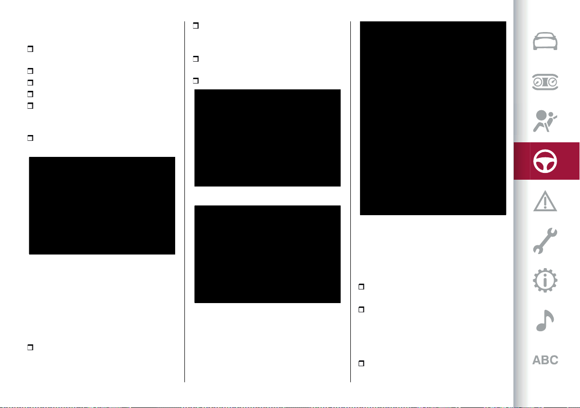
161
take out the dedicated adapter, located
underthe load platformfig.160;
openflapfig.156, pressing onthe point
shown by the arrow;
remove the closing cap;
put the cap back in position;
insert the adapter into the filler;
when you have finished refuelling,
remove the adapter, close the cap and
then close the flap;
finally put the adaptor back in the
luggage compartment.
160 07206V0005EM
Emergency fuel flap opening
In the event of an emergency the fuel flap
can be opened by operating from inside
the luggage compartment.
Versions with Cargo Box
Proceed as follows:
open the tailgate and then lift up the
loadbed fig.161;
liftthecover(1) fig.162 toaccessthe
emergency opening cable (2) fig. 163,
located by the side of the filler;
pull the cable in the direction indicated
by the arrow to release the fuel flap lock;
open the fuel flap by pressing it.
161 04206V0004EM
162 07226V0041EM
163 07226V0043EM
Versions with Cargo Box and space-
saver spare wheel
(where provided)
Proceed as follows:
open the tailgate and then lift up the
loadbed fig.161;
undo the locking device (1) fig. 162 and
extract the space-saver spare wheel
to reach the emergency opening cable
(1) fig.165 positioned onthe side ofthe
filler;
pull the cord to unlock the fuel flap;
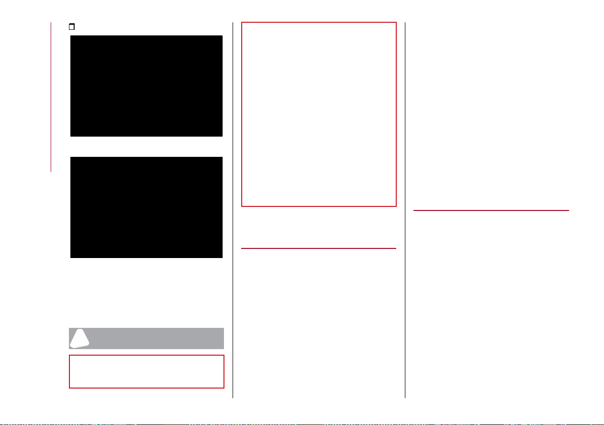
STARTING AND DRIVING
162
open the fuel flap by pressing it.
164 08066V0010EM
165 07226V0044EM
WARNING If the filler compartment is
washed with a high-pressure jet, keep it
at a distance of at least 20 cm.
WARNING
154) Do not apply any object/cap to the end
of the filler which is not provided for the
car. The use of non-compliant objects/plugs
could cause a pressure increase inside the
tank, resulting in dangerous situations.
155) Do not approach naked flames or lit
cigarettes to the fuel tank filler: fire risk.
Keep your face away from the fuel filler to
prevent breathing in harmful vapours.
156) Do not use a mobile phone near the
refuelling pump: risk of fire.
157) If the AdBlue overheats for a prolonged
period inside the tank to over 50 °C (for
example, due to direct solar irradiation),
the AdBlue may decompose and produce
ammonia vapours. Ammonia vapours have
a pungent odour when the cap of the AdBlue
tank is unscrewed, therefore be careful
not to inhale any ammonia vapours in the
tank outlet. In this concentration, however,
the ammonia vapours are not harmful or
dangerous to health.
AdBlue
®
(UREA) ADDITIVE FOR
DIESEL EMISSIONS
(2.2 JTD versions only)
The car is equipped with an UREA
injection system and Selective Catalytic
Reduction to meet emission standards.
These two systems ensure compliance
with the diesel emissions requirements;
at the same time, they ensure fuel-
efficiency, handling, torque and power.
For messages and system warnings,
refer to the "Warning lights and
messages" paragraph in the "Knowing
the instrument panel" chapter.
AdBlue
®
(UREA) is considered a very
stable product with a long shelf life.
Stored at temperatures LOWER than 32
°C, it has a shelf life of at least one year.
For more information on the AdBlue
®
liquid type, see the “Fluids and
lubricants” paragraph in the “Technical
specifications” chapter.
The car is provided with an automatic
AdBlue
®
heating system when the
engine starts allowing the system to
work correctly at temperatures lower
than -11 °C.
IMPORTANT AdBlue
®
freezes at
temperatures lower than -11 °C.
SUGGESTIONS FOR DRIVING
SAVING FUEL
Below are some suggestions which may
help you save fuel and thus lower the
amount of harmful emissions released
into the atmosphere.
Vehicle maintenance
Checks and operations should be carried
out in accordance with the "Service
Schedule" (see the "Maintenance and
care" chapter).
Tyres
Check the tyre pressures at least once
every four weeks: if the pressure is too
low, consumption levels increase as
resistance to rolling is higher.
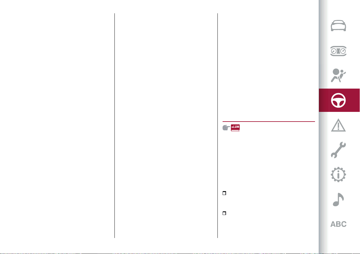
163
Unnecessary loads
Do not travel with an overloaded
boot. The weight of the vehicle and
its arrangement greatly affect fuel
consumption and stability.
Electric devices
Use electrical devices only for the
amount of time needed. The heated
rear window, additional headlights,
windscreen/rear window wipers and
heater fan need a considerable amount
of energy, therefore increasing fuel
consumption (by up to 25% in the urban
cycle).
Climate control system
Using the climate control system will
increase consumption: use standard
ventilation when the temperature
outside permits.
Devices for aerodynamic control
The use of non-certified spoilers may
adversely affect air drag and fuel
consumption.
DRIVING STYLE
Start
Do not warm up the engine at low or
high revs when the car is stationary;
this causes the engine to warm up
more slowly, thereby increasing fuel
consumption and emissions. It is
therefore advisable to move off
immediately, slowly, avoiding high
speeds: in this way the engine will warm
up more quickly.
Unnecessary actions
Avoid revving up when starting at
traffic lights or before stopping the
engine. The latter action, as well as
double-declutching, is unnecessary and
causes increased fuel consumption and
pollution.
Gear selection
Use a high gear when traffic and road
conditions allow it. Using a low gear
for faster acceleration will increase
fuel consumption. In the same way,
improper use of a high gear increases
consumption, emissions and engine wear.
Top speed
Fuel consumption increases considerably
with speed. Maintain a constant speed,
avoiding unnecessary braking and
acceleration, which cost in terms of both
fuel consumption and emissions.
Acceleration
Accelerating violently severely affects
consumption and emissions: acceleration
should be gradual and should not exceed
the maximum torque.
CONDITIONS OF USE
Cold starting
Short journeys and frequent cold starts
do not allow the engine to reach optimum
operating temperature. Consequently,
both consumption (from +15 to +30%
on the urban cycle) and emissions will
increase.
Traffic and road conditions
High fuel consumption is caused
by heavy traffic, for instance when
travelling in a queue with frequent use of
low gears or in cities with many traffic
lights. Winding mountain roads and rough
road surfaces also adversely affect
consumption.
Stops in traffic
During prolonged hold-ups (e.g. level
crossings) switch off the engine.
TOWING TRAILERS
158) 159)
TOW HOOK SETUP
Instructions for using the removable
ball head tow hook
WARNING Before setting off, check
that the removable ball head tow hook
is locked correctly. To do this, check the
following conditions:
the green mark on the knob must
coincide with the green mark on the tow
hook fixing bracket;
the knob must be at the end of its
travel, resting on the tow hook fixing
bracket (no crack);
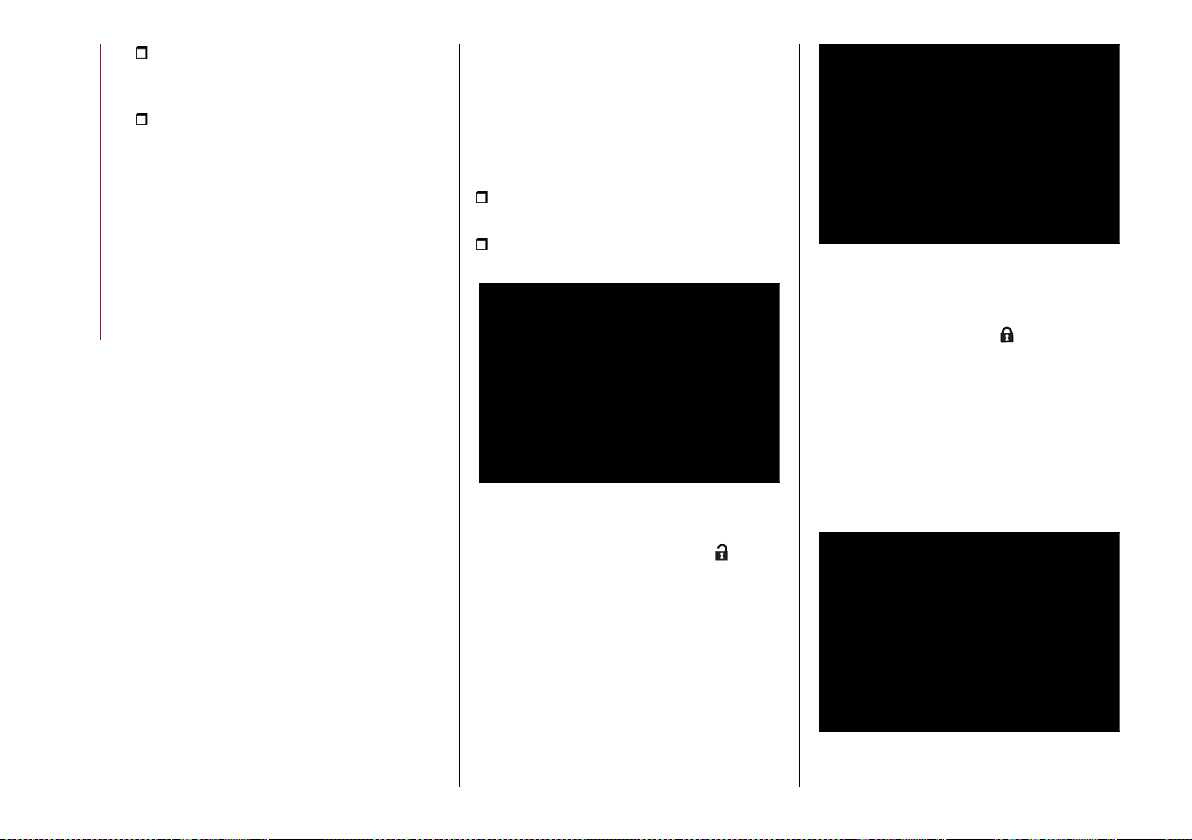
STARTING AND DRIVING
164
the lock on the knob must be locked
with the key removed. The knob cannot
be removed;
the tow hook fixing bracket must be
firmly attached to the mounting pipe on
the car. Check by shaking with a hand.
The installation procedure must be
repeated if any of these requirements is
NOT met.
If even only one of the requirements is
not met the tow hook must not be used,
since there is risk of causing accidents.
Contact an Alfa Romeo Dealership.
The ball head tow hook can be
fitted/removed manually without the
need for specific tools.
WARNING Never use cars or work tools:
the mechanism may be damaged.
WARNING Do not release the tow hook
when it is attached to a trailer or cargo-
carrier.
WARNING When driving without trailer
(or without a cargo-carrier), the ball head
tow hook must be removed and the
closing cap must always be inserted in
the hook mounting pipe. This applies
particularly if the tow hook reduces
visibility of the number plate or the
lighting system.
For the electrical connection, a 13 pin 12 V
DC connection is to be used (CUNA/UNI
and ISO/DIN Standards). Follow the
instructions provided by the vehicle
Manufacturer and/or the tow hook
Manufacturer.
Installing the tow hook
Before inserting the tow hook, you must
remove the access cover to the tow hook
fixing position under the rear bumper.
Remove the protection cap from the
towhookmountingpipefig.166;
get the tow hook from the luggage
compartment.
166 07216V0001EM
When you take out the tow hook, it is
usually in the released position ( ).
In this position, there is a gap of about
5 mm between the knob and the tow
hook fixing bracket. In addition, the red
mark on the knob should line up with the
green markonthe bracket,see fig. 167.
Only install the tow hook in these
conditions.
167 07216V0002EM
If the tow hook locking system is NOT
pretensioned before installation, or if it
is in the locked position ( ), pretension
it by following the “Hook pretensioning”
procedure described at the end of this
paragraph.
The tow hook is in the locked position
when the knob is resting on the bracket
(no crack) and the green mark on the
knob lines up with the green sign on the
bracket fig.168.
168 07216V0003EM
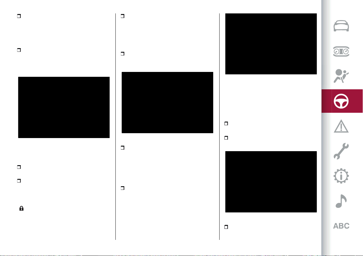
165
Position the tow hook so that the delta
inserts on the tow hook fixing bracket
are aligned with the crack between the
lower edge and the mounting pipe on the
carfig.169;
push the tow hook upwards and
the pretensioned mechanism will
automatically fasten itself in position.
160)
169 07216V0004EM
Use the supplied key to close the
mechanism:
insert the key into the lock on the knob,
turn it fully anticlockwise and remove it;
fasten the protection cap onto the
lock.
WARNING The key can only be removed
when the locking mechanism is closed
( ).
WARNING To prevent losing the key
while towing, DO NOT leave it in the lock.
Remove the ball protection cover from
the tow hook and attach the trailer.
Connecting the electrical system
To connect the trailer’s electrical system,
proceed as described below:
turn the connector mounting bracket
downwards. The bracket is to the left of
thetow hook mountingpipefig.170;
170 07216V0007EM
once you have lowered the protection
cover, insert the trailer’s plug into the
socket on the car. To make sure that the
two connectors fit together perfectly,
check that the tab on the plug is aligned
withthe notch onthe socketfig. 171;
insert the plug fully into the socket and
enable the safety lock, if provided.
171 07216V0008EM
Removing the tow hook
When the tow hook is no longer needed,
disconnect the electrical connections
and remove it from its position as
described below:
remove the protection cap and insert
the keyintothelockfig.172;
open the lock by turning the key fully
clockwise;
172 07216V0009EM
grab the tow hook and move the knob
away from the fixing bracket by pulling it
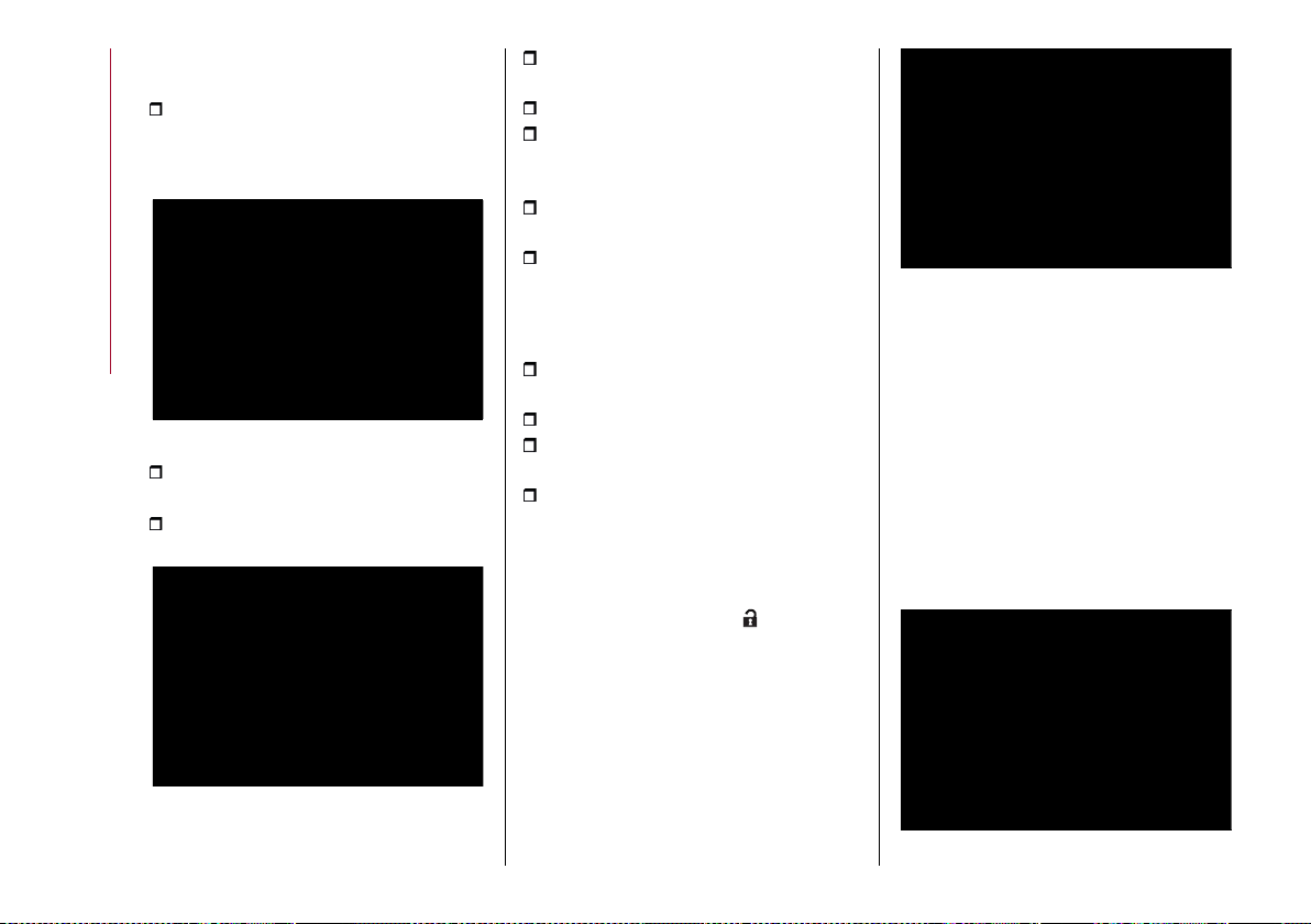
STARTING AND DRIVING
166
in the direction indicated by the arrow (A)
fig. 173;
to release the hook, turn the knob
clockwise (B), until the red mark on the
knob lines up with the green mark on the
bracket;
173 07216V0010EM
remove the tow hook from its position
fig. 174;
insert the protection cap into the tow
hook mounting pipe on the car;
174 07216V0011EM
clean the tow hook and remove any
residues, especially from the ends;
fit the protection cover onto the ball;
insert the tow hook into its case
and put it back inside the luggage
compartment;
fasten the cover onto the electrical
connector and push the mount upwards;
fit the cover onto the rear bumper.
Pretensioning the tow hook
If necessary, pretension the locking
mechanism as described below:
remove the cap from the lock on the
knob and insert the key provided;
turnthe key fully clockwise fig. 175;
pull the knob out in the direction
indicated by the arrow (A);
turn the knob (B) fully clockwise.
The locking mechanism will remain
pretensioned even when the knob is
released.
The tow hook, with pretensioned locking
mechanism (knob position ), is now
ready to be installed on the car.
175 07216V0012EM
ELECTRICALLY DRIVEN TOW HOOK
The tow hook and the socket for
connecting the trailer lights are fixed to
each other and are located behind the
rear bumper when they are not in use.
fig. 176.
During operation, the position of the
whole device (hook plus electrical
socket)iscontrolled bybutton 1 fig.177
on the right-hand luggage compartment
trim. The button must be pressed twice
within 4 seconds.
176 07216V0100EM
167
177 07216V0101EM
Thereis a LEDonthebutton1 fig.177,
which may be in one of the following
states:
LED off: indicates that at least one of
the above conditions is not met, or the
trailer light wiring is connected to the
socket;
Flashing LED (slow flashing):
indicates that the tow hitch is in motion;
LED flashing (rapid flashing):
indicates a failure of the tow hitch or that
the system must be initialized (see the
description in the following paragraph);
LED on fixed: indicates that the tow
hook can be moved.
System initialisation
If the tow hook is not correctly initialized,
the LED onbutton1fig.177 flashes
quickly.
In this case it is sufficient to move
the hook pressing the button: the
initialization will be performed
automatically.
During the initialization procedure the
tow hook will fully retract (if it was not
previously retracted), then it will come
out of its seat and will end its stroke in
the "fully extracted" position.
WARNING
158) The ABS with which the car is equipped
will not control the braking system of the
trailer. Particular caution is therefore
required on slippery roads.
159) Never modify the braking system of
the car to control the trailer brake. The
towing braking system must be completely
independent of the vehicle's hydraulic
system.
160) To avoid damage to your hands, keep
them away from the knob while inserting the
tow hook into position on the car bracket.

STARTING AND DRIVING
168
ASSEMBLY SCHEDULE
The tow hookstructuremust besecured tothebodyin the pointsshowninthe fig. 178.
Dimension D (see the figure): with the vehicle fully loaded: 330.35 mm, with the vehicle unladen: 350 to 420 mm
178 07226V0040EM
WARNING Contact an Alfa Romeo Dealership to install a tow hook.

A punctured tyre or a burnt-out bulb?
At times, a problem may interfere with our journey.
The pages on emergencies can help you to deal with critical
situations independently and with calm.
In an emergency we recommend that you call the freephone
number found in the Warranty Booklet.
You can also use the universal, national or international
freephone number to find your nearest Alfa Romeo
Dealership.
IN AN EMERGENCY
HAZARDWARNINGLIGHTS............................................ 170
SOSCALLANDASSISTCALL .......................................... 170
REPLACINGABULB ......................................................174
REPLACINGFUSES...................................................... 179
CHANGINGAWHEEL....................................................185
TYREREPAIRKIT ........................................................188
RUNFLATTYRES........................................................190
EMERGENCYSTARTING ...............................................190
FUELCUT-OFFSYSTEM................................................ 193
AUTOMATICTRANSMISSIONGEARLEVERRELEASE ............. 193
TOWINGTHEBROKEN-DOWNCAR ................................... 193
TOWINGTHECAR ....................................................... 193
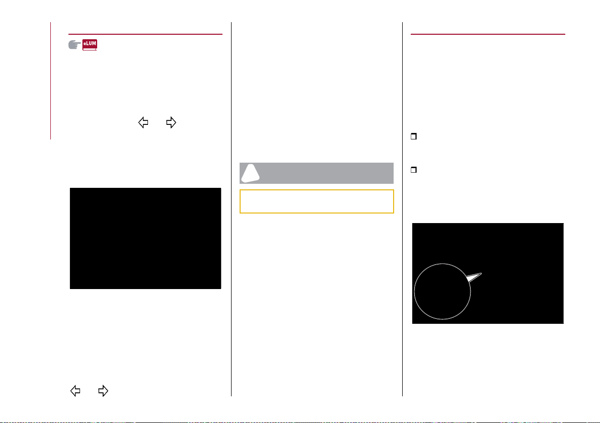
IN AN EMERGENCY
170
HAZARD WARNING LIGHTS
CONTROL
66)
Press hazard lightsbuttonfig.179 to
switch the lights on/off.
When the hazard warning lights are on,
the warning lights and flash.
When you need to move away from
the vehicle to look for help, the hazard
warning lights will continue flashing
even if the ignition device is in the STOP
position.
179 08016V0001EM
WARNING The use of hazard warning
lights is governed by the highway code
of the country you are driving in: comply
with legal requirements.
Emergency braking
Emergency braking The hazard lights
are switched on and warning lights
and appear on the instrument
panel in case of emergency braking and
according to the mode selected by the
“Alfa DNA™” selector.
When the "Alfa DNA™" selector is
in position "n" or "a", the activation
threshold of the hazard warning lights is
higher; on the other hand, in position "d"
the sensitivity of the activation is lower
than that in the "n" and "a" modes.
The lights switch off automatically when
emergency braking ceases.
IMPORTANT
66) A prolonged use of the hazard warning
lights may discharge the battery.
SOS CALL AND ASSIST CALL
(for versions/markets where provided)
The car is equipped with on-board
assistance functions designed to provide
support in the event of accident and/or
emergency (SOS) or malfunctions of the
vehicle (roadside assistance - ASSIST)
managed by means of Alfa Connect Box.
The SOS function is activated:
automatically in the event of a major
collision recorded by the device aboard
the vehicle;
manually, by pressing the SOS button
located onthe ceilinglightfig. 180 or
by means of the appropriate menu
fig. 181 on theConnectsystem(for
versions/markets, where provided).
180 04136S0073EM
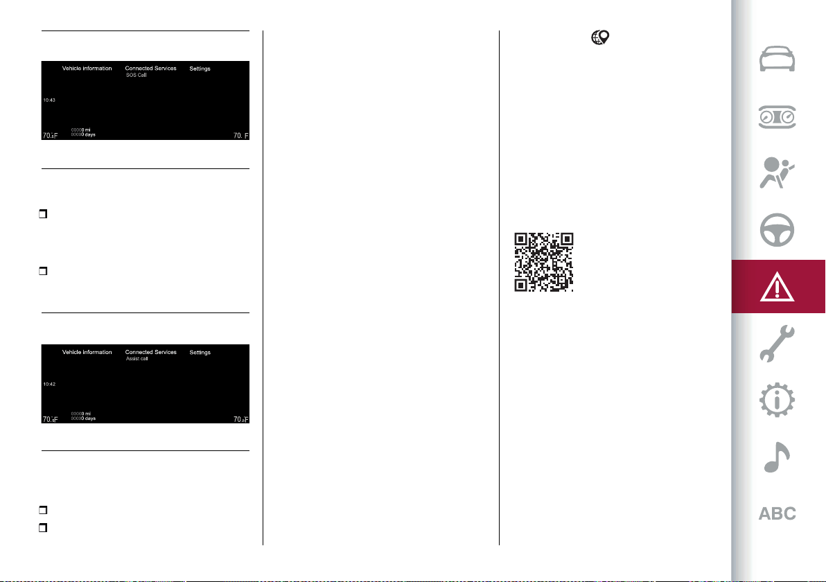
171
SOS
10:43
°
5
181 12126S2098EM
The ASSIST function is activated:
manually by selecting the appropriate
menufig. 182 onthe Connectsystem (for
versions/markets where provided).
182 12126S2099EM
The SOS and ASSIST functions are
active with:
ignition device is at ON;
ignition device in STOP position and
Connect system display on.
NOTE If the SOS or Assist functions do
not work, the fault in the system will be
indicated on the display. Go as soon as
possible to an authorised workshop to
have the function repaired.
NOTE The correct operation of the SOS
and ASSIST services will be guaranteed
only by a good network coverage.
Privacy: GPS location is always
active, for both SOS and Assist calls.
Deactivating it via the menu items in the
"Settings" menu of the Connect system
will make some with other services
unavailable (see the "Settings" chapter
of the Connect system for more details).
MANUAL SOS CALL
In the event of need, hold the SOS
button on the front ceiling light fig. 178
pressed for 2 seconds or press the
button fig. 179 on the Connect display
(for versions/markets where provided).
automatically (for versions/markets,
where provided) following malfunctions
of the braking system, fuel system,
engine, etc.
After the SOS and ASSIST functions
(for versions/markets, where provided)
have been activated automatically or
manually, pressing the corresponding
button will send the position data to the
operational centre and make a voice call
to an operator.
WARNING The icon is shown at the
bottom left of the Connect system
display when the geolocation function
is active (ON). When geolocation is on,
the vehicle position is tracked to enable
the functions that require it. When
geolocation is off, the vehicle position is
only tracked by the navigation, safety,
insurance and driver assistance systems
(where provided). See the Connect
system "Settings" chapter to deactivate
the function.
WARNING The SOS Call and ASSIST Call
functions may not be available for the
first minute after the vehicle is started.
The SOS button located on the ceiling
light will light up after connecting to an
SOS operator and will turn off when the
connection is ended.
IN AN EMERGENCY
172
WARNING If not subscribed to the
SOS service, if the service is not
available on the market/version or has
expired, pressing the system button
will make an automatic call to the
national public emergency number (for
versions/markets, where provided). In
this case, no data will be sent and the
request will be made only in voice mode.
WARNING If the SOS emergency
service is activated, the call will be
automatically routed to a private
Call Centre. We hereby specify that,
whenever the SOS call is referred to the
text, the SOS call is to be considered
managed by private service providers.
The SOS call service is not the e-call
system for emergency calls provided
for by the applicable European
Community legislation for newly
type-approved vehicles.
WARNING Any malfunctions detected by
the SOS calling system will be notified:
during the start-up phase;
when the malfunction is detected;
by displaying a respective message on
the Connect system display. Contact
an Alfa Romeo Dealership as soon as
possible.
WARNING In the event of danger
(fire, visible smoke or hazardous road
conditions or dangerous positions), do
not wait for voice contact with the SOS
service operator, but exit from the car
immediately and go to a safe place, if in a
condition to do so.
WARNING Do not place network
antennas, CB radios or aftermarket
electrical equipment to avoid
interference Such interference could
prevent the system form making the
emergency call.
WARNING Ignoring malfunction
warnings displayed by the Connect
system for a long time could lead to
being unable to make an SOS call when
needed.
Even if the SOS call system is fully
functional, factors outside the control
of FCA could interfere with or prevent
operation of the SOS call. Such factors
can be caused by the car electrical
systems not being intact, damage to
the SOS system during the accident,
obstructed or unavailable satellite
signals, network congestion, adverse
weather conditions, buildings, interfering
structures, tunnels, etc.
ASSIST CALLS
Pressing the graphic buttons fig. 180
located on the display of the Connect
system (for versions/markets, where
NOTE If the SOS call button is pressed
by mistake, it is possible to press it
again within 10 seconds to cancel the
operation or press the cancel button on
the Connect system display.
Once the connection has been
established, the following data will
be automatically transmitted to the
Operations Centre, as authorised by the
customer:
indication that the occupant has made
an SOS call;
the brand of the vehicle;
the most recent known GPS
coordinates of the vehicle.
If you are able to speak to the operator,
do so through the car audio to provide
additional information about the request
for help.
If the system is unable to establish the
voice call, or the line disconnects due to
insufficient coverage, the SOS service
will try to call the operational centre
again for 5 minutes.
If the operational centre needs to
contact the car again, the system can
receive an incoming call, which will be
accepted automatically.
173
The call will be made through the car
audio system to provide any additional
information about the assistance
request.
If the system is unable to establish the
voice call, or the line disconnects due
to insufficient coverage, the ASSIST
service will try to call the operational
centre again for certain number of times.
WARNING If you have not subscribed
to the related services or the Roadside
Assistance package has expired or is
unavailable for purchase, the ASSIST
call will not be available. For further
information visit the Alfa Romeo official
website.
WARNING If the ASSIST call system
detects a malfunction, it is indicated by a
corresponding message on the Connect
system display. Contact an Alfa Romeo
Dealership as soon as.
If an emergency call (SOS) is active and
an ASSIST call is requested, the latter
will not be delivered.
Alfa Connect Box SYSTEM BATTERY
The Alfa Connect Box system is provided
with an independent battery that allows
the operation of some connected
services even if the car battery is
disconnected.
The system will warn the user of
the need to replace this battery by
displaying a dedicated message on
the display of the Connect system (for
versions/markets where provided) and
by means of a notification via mobile app
(for versions/markets, where provided).
Go to an Alfa Romeo dealership as soon
as possible.
NOTE: Failure to replace the battery
and, consequently, failure to observe
the warnings provided by the system
could affect or entirely prevent service
operation.
NOTE Regardless of charge, the battery
must be replaced every 5 years by an
Alfa Romeo dealership.
the type of error that occurred on
the vehicle that automatically sent
the ASSIST request (in the case of an
automatic call - for versions/markets,
where provided).
provided) to call to one or more of the
following services:
Roadside Assistance: if case of need,
a connection will be established with the
roadside assistance authority which will
receive the vehicle type and its position
directly. Additional roadside assistance
charges may apply.
Customer Care (for versions/markets,
where provided): Customer service to
provide support in case of problems to
the car.
NOTE The relative menus and the
Connect system status bar will change
display state depending on the actions
performed, and it will be possible to
monitor each stage of the assist call
(connection, duration, ending, connection
errors, etc.).
NOTE If the ASSIST call button is
pressed by mistake, the call can be ended
by pressing the cancel button on the
Connect system display.
Once the connection has been
established, the following data will be
automatically transmitted, as authorised
by the customer:
indication that the occupant has made
an ASSIST call;
the brand of the vehicle;
the most recent known GPS
coordinates of the vehicle;
IN AN EMERGENCY
174
WARNING
161) Before replacing the bulb, wait for the
exhaust ducts to cool down: DANGER OF
SCALDING!
162) Modifications or repairs to the electric
system that are not carried out properly
or do not take the system technical
specifications into account can cause
malfunctions leading to the risk of fire.
163) Halogen bulbs contain pressurised
gas, in the case of breakage they may burst
causing glass fragments to be projected
outwards.
164) Only replace the light bulbs when the
engine is off and in a position that does not
interfere with traffic and lets you safely
replace them (see the description in the
“Replacement” paragraph). Also ensure
that the engine is cold, to prevent the risk of
burns.
IMPORTANT
67) Halogen bulbs must be handled holding
the metallic part only. Touching the
transparent part of the bulb with your
fingers may reduce the intensity of the
emitted light and even reduce the lifespan
of the bulb. In the event of accidental
contact, wipe the bulb with a cloth
moistened with alcohol and let the bulb dry.
REPLACING A BULB
161) 162) 163) 164)
67)
GENERAL INSTRUCTIONS
Before replacing a bulb check the
contacts for oxidation;
replace blown bulbs with others of the
same type and power;
after replacing a headlight bulb, always
check its alignment;
when a light is not working, check that
the corresponding fuse is intact before
changing the bulb. For the location of
fuses, refer to the paragraph "If a fuse
blows" in this chapter.
WARNING In some particular climate
conditions such as low temperature,
humidity or after washing the car, a thin
condensation layer may form on the
internal surfaces of the front and rear
headlights. This is a natural phenomenon
due to the difference in temperature
and humidity between the inside and the
outside of the transparent cover which
does not indicate a fault and does not
compromise the normal operation of
lighting devices. It will disappear during
normal use.
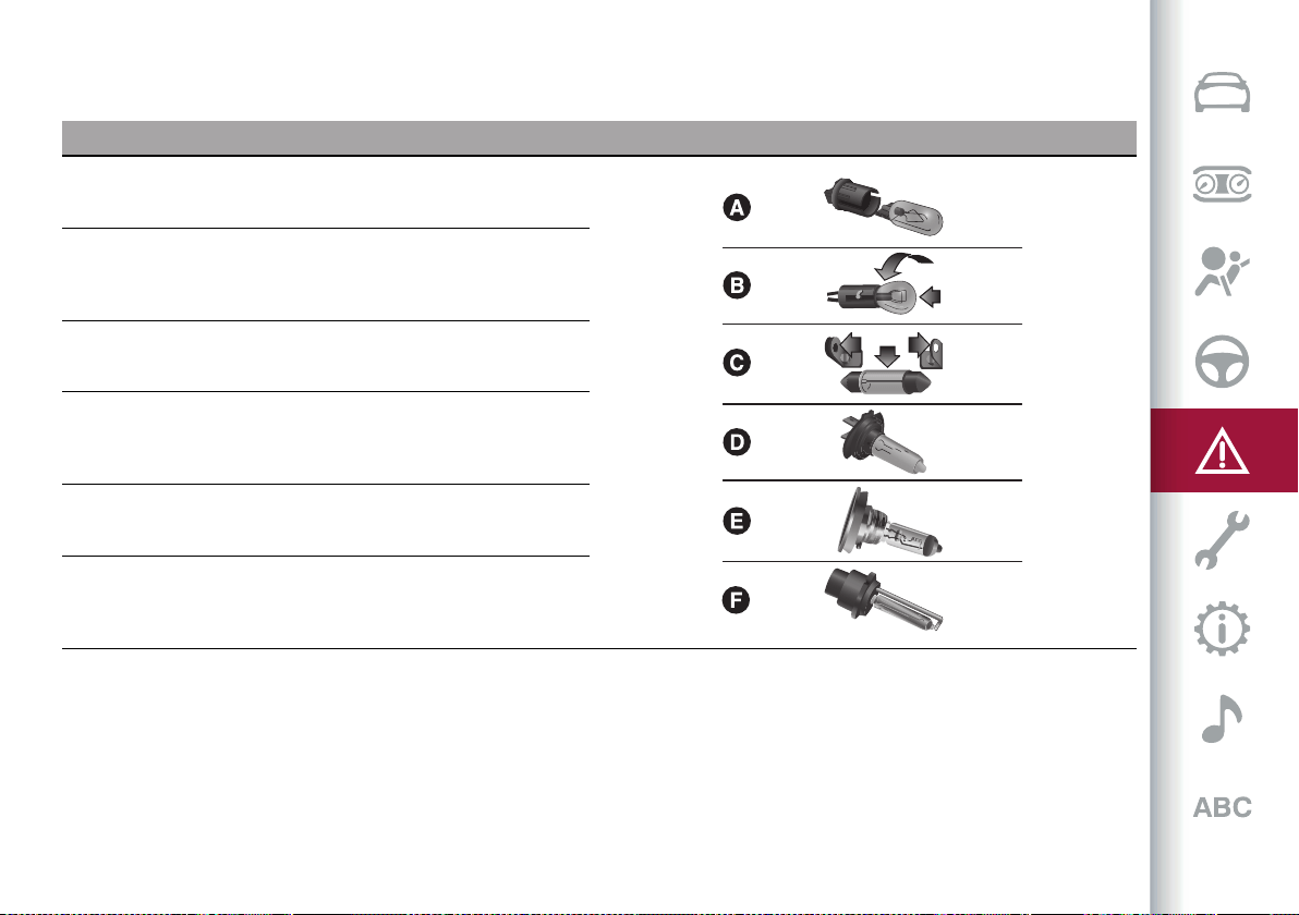
175
BULB TYPES
The car is equipped with the following bulbs
Glass bulbs (type A): they are press-fitted. Pull to extract.
Bayonet-type bulbs (type B): to remove them from their holder, press
the bulb and turn it anticlockwise, then extract it.
Tubular bulbs (type C): release them from their contacts to remove.
Halogen bulbs (type D): to remove the bulb, turn the connector to the
side and pull it out.
Halogen bulbs (type E): to remove the bulb, turn it anticlockwise.
Xenon gas discharge bulb (type F): to remove the bulb, contact an Alfa
Romeo Dealership.
IN AN EMERGENCY
176
Light bulbs Type Power Figure reference
Main beam headlights, front side lights/daylight running lights
(DRL) (*)
H15 55/15W D
Dipped beam headlights (*) H7 55W D
Front direction indicators (*) PY24W 24W B
Fog lights (*) H11 55W E
Main beam/dipped beam headlights (Xenon gas discharge) D3S 35W F
Sun visor light 1.5CP 2.1W C
Glove compartment light W5W 4W A
Boot light W5W 5W A
Puddle lights (under door panel) W5W 5W A
(*) Only for basic version headlight with halogen main beam/dipped beam headlights
177
REPLACING AN EXTERNAL BULB
Front light cluster with main
beam/dipped beam halogen headlights
Dipped beam headlights
To change the bulb of these lights,
proceed as follows:
operating inside the engine
compartmentfig. 183;
183 08026V0023EM
removethe coverfig.184;
184 08026V0002EM
remove the bulb/connector assembly
fromthe headlightbodyfig.185;
185 08026V0003EM
remove the bulb by sliding it off the
connector;
install the new bulb, making sure it is
correctly inserted in the connector;
then insert the bulb/connector
assembly in the housing on the headlight
body and make sure that it is locked
correctly;
remount the lid and cover, tightening
the fixing bolts.
Main beam headlights
To change the bulb of these lights,
proceed as follows:
operating inside the engine
compartment fig. 186;
186 08026V0023EM
removethe coverfig.187;
187 08026V0004EM
turn the bulb, bulb holder and
connector assembly anticlockwise and
then slide it off the headlight body
fig. 188;
IN AN EMERGENCY
178
188 08026V0005EM
remove the bulb by sliding it off the
bulb holder;
install the new bulb, making sure it is
correctly inserted in the bulb holder;
then insert the bulb, bulb holder and
connector assembly in the housing on
the headlight body and turn it clockwise,
making sure that it is locked correctly;
refit the protective cover.
Direction indicators
To change the bulb of these lights,
proceed as follows:
operating inside the engine
compartment fig. 189;
189 08026V0023EM
remove cover by turning itfig.190;
190 08026V0006EM
release the bulb, bulb holder and
connector assembly and then slide it off
the headlightbodyfig.191;
191 08026V0007EM
remove the bulb by sliding it off the
bulb holder;
install the new bulb, making sure it is
correctly inserted in the bulb holder;
then insert the bulb, bulb holder and
connector assembly in the housing on
the headlight body and turn it clockwise,
making sure that it is locked correctly;
refit the protective cover.
Fog lights
(where provided)
To replace the fog lights, contact an Alfa
Romeo Dealership.
Front light cluster with main
beam/dipped beam Xenon gas
discharge headlights
To replace the bulbs of the main beam
headlights/dipped headlights contact an
Alfa Romeo Dealership.
179
REPLACING FUSES
GENERAL INFORMATION
165) 166) 167) 168) 169)
68) 69)
Fuses protect the electrical system: they
intervene (blow) in the event of a failure
or improper action on the system.
Fuse extracting pliers
To replace a fuse, use the tongs housed
in the luggage compartment fusebox
cover fig.192.
Grab the pliers from the upper tabs,
press them and extract the pliers pulling
upwards.
192 08036V0053EM
The pliers fig. 191have two different
ends, specifically designed to remove the
different types of fuse present in the car:
1: MINI fuse;
2: J-CASE fuse.
193 08036S0005EM
After use, refit the pliers in position,
proceeding as follows:
grasp the pliers from the upper tabs;
press the tongs in their housing,
pushing downwards, until they click into
place.
FUSE LOCATION
The fuses, which can be replaced by the
user, are grouped in two boxes below the
passenger side foot board and inside the
boot.
FUSEBOX UNDER PASSENGER SIDE
FOOTBOARD
To access the fuses, proceed as follows:
lift the upper end of the footboard (1)
fig.194 on the passengerside,pullingitto
release the 2 buttons;
194 08036V0010EM
remove the panel(2) fig.195,
extracting it downward, after unscrewing
the two fixing hooks;
195 08036V0011EM
the fuses are freely accessible on the
control unit.
The number identifying the electrical
component corresponding to each fuse is
shown on the control unit cover.
LUGGAGE COMPARTMENT FUSEBOX
To access the fuses, proceed as follows:
IN AN EMERGENCY
180
remove the cover located on the right
side of the compartment;
removethefuseboxcoverfig.196;
196 08036V0014EM
The number identifying the electrical
component corresponding to each fuse is
shown on the cover.
After replacing a fuse, make sure that
you have closed cover correctly.
WARNING
165) Never replace a fuse with another with
a higher amp rating; RISK OF FIRE.
166) Before replacing a fuse, make sure
that the ignition device is at STOP and
that all devices are switched off and/or
disconnected.
167) Contact an Alfa Romeo Dealership
if a safety system (air bags, brakes),
transmission system (engine, gearbox) or
steering system general protection fuse
blows.
168) If a fuse blows again, contact an Alfa
Romeo Dealership.
169) If a general protective fuse (MAXI-
FUSE, MEGA-FUSE, MIDI-FUSE) blows,
contact an Alfa Romeo Dealership.
IMPORTANT
68) Never replace a faulty fuse with metal
wires or anything else.
69) If it is necessary to wash the engine
compartment, take care not to directly hit
the fusebox and the window wiper motors
with the water jet.

181
FUSEBOX UNDER PASSENGER SIDE FOOTBOARD
197 08036S0013EM
FUNCTION FUSE AMPERE
Front electric window (driver side) F33 25
Front electric window (passenger side) F34 25
Power supply for Connect system, Climate Control system,
Alarm, Electric door mirror folding, EOBD system, USB port
F36 15
IN AN EMERGENCY
182
FUNCTION FUSE AMPERE
Power Lock Device (Driver side door unlocking - where
provided)/Door unlocking, Central locking
F38 20
Windscreen washer pump F43 20
Rear left electric window F47 25
Rear right electric window F48 25
Heater rear window coil, cigar lighter F94 15
183
LUGGAGE COMPARTMENT FUSEBOX
198 08036V0015EM
FUNCTION FUSE AMPERE
Tow hook module (TTM/TTEBM) F01 40
Hi-Fi system F08 30
I-Drive / USB Socket / AUX / USB Charger F21 10
KL15/a 12V Luggage compartment power socket F22 20
IN AN EMERGENCY
184
FUNCTION FUSE AMPERE
Trailer light control unit power supply (+30) F1 20
Trailer light control unit power supply (+30) F2 15
Trailer socket (only EMEA) (+30) F3 10
Tow bar (+15) F4 10
185
CHANGING A WHEEL
GENERAL INSTRUCTIONS
The car is equipped with the "Tyre Repair
Kit": see the “Tyre Repair Kit” paragraph
for how to use this device.
As an alternative to the “Tyre Repair Kit”,
the car may be requested with a space-
saver wheel: see the instructions on the
following pages for changing the wheel.
JACK
170) 171)
Please note that:
the jack weighs about 4.4 lb (2 kg);
the jack requires no adjustment;
the jack cannot be repaired and in the
event of a fault it must be replaced by
another genuine one;
no tool other than its cranking device
may be fitted on the jack.
Jack maintenance:
prevent any dirt from depositing on
the "worm screw";
keep the "worm screw" lubricated;
never modify the jack.
Conditions in which not to use the jack:
temperatures below −40°F (-40°C);
on sandy or muddy ground;
on uneven ground;
on steep slopes in extreme weather
conditions: thunderstorms, typhoons,
hurricanes, blizzards, storms, etc.;
in direct contact with the engine or for
repairs under the car;
on boats.
CHANGING PROCEDURE
172) 173) 174) 175) 176) 177) 178)
70) 71)
Proceed as follows:
stop the car in a position that is not
dangerous for oncoming traffic where
you can change the wheel safely. The
car must be stopped in a lay-by, car-
park or parking or service area, and the
ground must be as level as possible and
sufficiently compact;
stop the engine, engage the hazard
warning lights and the electric parking
brake and activate P (Park) mode;
make sure that any passengers get
out of the car and go to a safe place
where they will not obstruct traffic or
be exposed to the risk of injury. In the
event of a puncture, change the tyre in
accordance with the laws of the country
in which you are travelling. Wear the
reflective safety jacket (compulsory by
law) before getting out of the car;
open the luggage compartment and lift
up the mat using the handle;
when the situation dictates it (for
your own safety and to comply with the
regulations in force in the country where
you are), take the warning triangle and
position it at a suitable distance from the
car;
unscrewthe lockingdevice(1)fig.199,
take out the space-saver wheel and the
inflation compressor;
199 08066V0010EM
remove the damaged wheel by taking
the wrench(3) fig.200 andloosening the
fixing bolts by about one turn. Shake the
car to help detach the rim from the wheel
hub;
200 08066V0012EM
IN AN EMERGENCY
186
position the jack(4) fig.201 under
the car, near the wheel to be changed,
taking care not to damage the plastic
aerodynamic guard;
lift the extension lever (2) on the
wrench (3);
201 08066V0013EM
turn the extension lever (2) clockwise
until the round pin on the jack engages in
the hole in the lifting block located about
15 cm from the outside edge of the body.
Thelifting points(5) are shown infig.201
and are marked by a triangle on the
aerodynamicspoiler fig.202;
202 09056V0001EM
warn anybody nearby that the car is
about to be raised;
they should stay clear and they should
be warned not to touch the car until it is
back on the ground;
turn the extension lever (2) until the
wheel is a few centimetres off the
ground;
remove the five wheel fastening bolts
and take the wheel off;
make sure the contact surfaces
between space-saver wheel and hub are
clean so that the fastening bolts will not
come loose;
fit the space-saver wheel by inserting
the first bolt for two threads into the
hole closest to the valve;
take the wrench (3) and fully tighten
the fixing bolts;
inflate the space-saver wheel by
removing the cap from its inflation valve
and screwing on the compressor inflation
hosefitting(6) fig.203;
make sure that the switch (8) on the
compressor (6) is in the (0) (off) position,
open the rear hatch and insert the plug
into the power socket in the luggage
compartment or on the central tunnel
and start the engine. Put the switch (8) in
the (I) (on) position;
inflate the space-saver wheel to a
pressure of 43.5 psi (3 bar);
203 08066V0011EM
WARNING To conserve the battery
charge, it is recommended to leave the
vehicle running for the entire inflation
process.
To obtain a more accurate reading, it is
advisable to check the pressure of the
space-saver wheel on the pressure gauge
(7) with the compressor off.
187
The compressor was designed
exclusively for inflating the space-saver
wheel. Do not use it for inflating
mattresses, rafts, etc.
operate the extension lever (2) on the
jack (4) to lower the car;
then extract the jack (4);
use the wrench (3), to fully tighten the
bolts, passing alternately from one bolt
to the opposite one.
When replacing an alloy wheel, it is
advisable to place it upside down, with
the aesthetic part facing upwards.
WARNING
170) The jack may be used to replace wheels
only on the car that it comes with or other
cars of the same model. Never use the jack
for other purposes, such as lifting other
vehicle models. Never use it for repair
operations under the vehicle. Incorrect
positioning of the jack may cause the
vehicle to fall. Do not use the jack for loads
higher than the one shown on its label.
171) The jack is a tool developed and
designed only for changing a wheel, if a tyre
gets punctured or damaged, on the vehicle
with which it is supplied or on other vehicles
of the same model. Any other use, e.g. to
jack up other vehicle models or different
things, is strictly prohibited. Never use for
maintenance or repair activities under the
car or to exchange the summer/winter
wheels and vice versa. Never go under the
raised vehicle. Should it be necessary to
work under the vehicle, contact an Alfa
Romeo Dealership. Incorrect positioning
of the jack may cause the raised vehicle
to fall: use only in the positions indicated.
Do not use the jack for loads higher than
the one shown on its label. Never start the
engine with vehicle raised. If the vehicle is
raised more than necessary, everything can
become more unstable, with the risk of the
vehicle dropping violently. Thus, lift the
vehicle only as needed in order to access the
spare wheel.
172) The space-saver spare wheel is specific
for your car. Do not use it on cars of
different models. Do not use space-saver
wheels of different models on your car.
The space-saver wheel must only be used
in the event of an emergency. Never use it
for more than strictly necessary and never
exceed 80 km/h. On the space-saver wheel
there is an orange label, summarising the
main warnings regarding space-saver wheel
usage restrictions. Never remove or cover
the label. Never apply any hub cap to the
space-saver wheel.
173) Alert other drivers that the car
is stationary in compliance with local
regulations: hazard warning lights, warning
triangle, etc. Any passengers on board
should leave the car, especially if it is
heavily laden. Passengers should stay away
from on-coming traffic while the wheel is
being changed. On hills or uneven roads, use
chocks or appropriate objects to block the
wheels of the vehicle.
174) If left in the passenger compartment,
the punctured wheel and jack constitute
a serious risk to the safety of occupants
in the event of accidents or sharp braking.
Therefore, always place both the jack and
punctured wheel in the dedicated housing in
the boot.
175) It is extremely dangerous to attempt to
change a wheel on the side of the car next to
the driving lane: make sure that the car is at
a sufficient distance from the road, to avoid
being run over.
176) Indicate the presence of the stationary
car in accordance with current regulations:
hazard warning lights, warning triangle,
etc. Those on board should get out of the
car, especially if it is heavily laden, and wait
for the wheel to be replaced away from the
threat posed by the traffic.
177) Never tamper with the inflation valve.
Never introduce tools of any kind between
the rim and the tyre. Check tyre and space-
saver wheel pressures regularly, complying
with the values given in the "Technical
specifications" chapter.
178) The spare wheel must only be used in
an emergency. Never use it for more than
strictly necessary and never exceed 80
km/h. On the wheel there is an orange
sticker, summarising the main warnings
regarding wheel usage restrictions. Never
remove or cover the label. The label contains
the following indications in four languages:
"Warning! For temporary use only! 80 km/h
max.! Replace with standard wheel as soon
as possible. Never cover this indication."
Never apply a wheel cap on the wheel.
The driving characteristics of the car will
be modified with the wheel fitted. Avoid
violent acceleration and braking, abrupt
steering and fast cornering. Have the wheel
repaired and refitted as soon as possible.
Using two or more spare wheels at the same
time is forbidden. Do not apply grease to the
IN AN EMERGENCY
188
bolt threads before fitting: they could come
unscrewed.
IMPORTANT
70) When turning the jack handle make sure
that it can turn freely without scraping
your hand against the ground. The moving
components of the jack ("worm screw"
and joints) can also cause injuries: avoid
touching them. If you come into contact
with lubricating grease, clean yourself
thoroughly.
71) Contact an Alfa Romeo Dealership
as soon as possible to have the correct
tightening of the wheel bolts checked.
TYRE REPAIR KIT
DESCRIPTION
179) 180) 181) 182) 183) 184) 185) 186) 187) 188)
72)
3)
The Tyre Repair Kit is located in the
luggage compartment, inside a dedicated
container marked with the Alfa Romeo
logo.
To access the Tyre Repair Kit, open the
boot, lift the load platform.
The Tyre Repair Kit includes also:
aspraycan(1)fig. 204 ofsealant,with
filling : tube (2);
a compressor (4) complete with
pressure gauge, fittings and an adhesive
label (3) with the words Max. 80 km/h”, to
be attached in a position easily visible to
the driver (eg. on the dashboard) after
repairing the tyre;
some adaptors, for inflating different
elements.
204 08066V0002EM
WARNING The sealing liquid is effective
for outside temperatures between -40°F
and 122°F (-40°C and +50°C). The sealant
has an expiry date.
INFLATION PROCEDURE
179) 180) 181) 182) 183) 184) 185) 189) 187) 188)
Proceed as follows:
stop the car in a position that is not
dangerous for oncoming traffic where
you can repair the tyre safely, as far as
possible from the side of the road;
turn on the hazard warning lights;
engage the electric parking brake;
engage P (Park) mode;
stop the engine and put on the
reflective safety jacket (for your
own safety and to comply with the
regulations in force in the country where
you are) before getting out of the car.
when the situation requires it (for
your own safety and to comply with the
regulations in force in the country where
you are), take the warning triangle from
the luggage compartment and position it
at a suitable distance from the car.
put on the gloves, connect the tube
(5) fig.205 tothespraycan(1) usingthe
connector (6). Unscrew the tyre valve cap
and screw the filler pipe ring nut (2) onto
the tyre valve;
205 08066V0004EM
makesure thatswitch(7) fig.206 of
the compressor (4) is in (0) (off) position;
189
206 08066V0005EM
insert the plug into the socket in
the passenger compartment or in the
luggage compartmentfig.207 and start
the engine;
207 08066V0006EM
switch on the compressor by turning
theswitch(7) fig.206 to the (I)(on)
position;
inflate the tyre to a pressure of at
least 32 psi (2.2 bar). In order to obtain a
more precise reading, check the pressure
value on pressure gauge (8) with the
compressor off;
if a pressure of at least 26 psi (1.8 bar)
is not reached within 15 minutes, the
tyre is too damaged to be repaired. Do
not continue driving, but contact an Alfa
Romeo Dealership;
after having driven for about 5 miles
(8 km), stop, engage the electric parking
brake and recheck the tyre pressure;
if the measured pressure is unchanged
(32 psi / 2.2 bar), continue driving to an
Alfa Romeo Dealership;
if the measured pressure is between
19 psi and 30.5 psi (1.3 and 2.1 bar), restore
pressure to 32 psi (2.2 bar), continue
driving to an Alfa Romeo Dealership;
if the measured pressure is lower than
19 psi (1.3 bar), the tyre is too damaged to
be repaired. Do not continue driving, but
contact an Alfa Romeo Dealership.
WARNING Only use original tyre repair
cannisters, which can be purchased at an
Alfa Romeo Dealership.
WARNING To conserve the battery
charge, it is recommended to leave the
vehicle running for the entire inflation
process.
WARNING
179) Punctures on the sides of the tyre may
not be repaired. Do not use the Tyre Repair
kit if the tyre was damaged as a result of
being used when underinflated.
180) Always put on protective gloves before
proceeding with the operation.
181) Apply the adhesive label where it can
be easily seen by the driver as a reminder
that the tyre has been treated with the Tyre
Repair Kit. Drive carefully, particularly on
bends. Do not exceed 80 km/h. Avoid sudden
acceleration or braking.
182) You must always indicate that the tyre
was repaired using the Tyre Repair Kit. Give
the booklet to the technicians who will be
handling the tyre that was treated using the
Tyre Repair Kit.
183) Repairs are not possible in the case
of damage to the wheel rim (bad groove
distortion causing air loss). Do not remove
foreign bodies (screws or nails) from the
tyre.
184) Never operate the compressor for
longer than 20 consecutive minutes.
Risk of overheating. The Tyre Repair
Kit is not suitable for definitive repairs,
so the repaired tyres may only be used
temporarily.
185) As required by current regulations,
the information on chemical substances
for the protection of human health and the
environment and on the safe use of the
sealing fluid are on the packaging label.
Compliance with the indications on the
label is an essential condition to ensure the
safety and the effectiveness of the product.
Remember to carefully read the label before
IN AN EMERGENCY
190
use; the user of the product is responsible
for any damages caused by improper use.
The sealing fluid has an expiry date. Replace
the bottle if the sealant has expired.
186) If the pressure falls below 1.3 bar, do
not drive any further: the Tyre Repair Kit
cannot guarantee proper seal because the
tyre is too damaged. Contact an Alfa Romeo
Dealership.
187) The Tyre Repair Kit provide a
temporary repair, therefore the tyre must
be examined and repaired by a specialist as
soon as possible. The sealant is suitable
for use at temperatures in the range from
−40°C to +50°C.
188) Indicate the presence of the stationary
car in accordance with current regulations:
hazard warning lights, warning triangle, etc.
Those on board should get out of the vehicle
and wait for the wheel to be repaired away
from the threat posed by the traffic. If
parked on a slope or rough surface, chock
the wheels with wedges or other suitable
devices (for the correct procedure for
parking the car safely, refer to the "Parking"
paragraph in the "Starting and driving"
chapter).
189) If the pressure falls below 1.8 bar, do
not drive any further: the Tyre Repair Kit
cannot guarantee proper seal because the
tyre is too damaged. Contact an Alfa Romeo
Dealership.
IMPORTANT
72) In the event of a puncture caused by
foreign bodies, the kit may be used to repair
tyres showing damage on the tyre tread up
to max. 6 mm diameter.
IMPORTANT
3) Dispose of the bottle and the sealant
liquid properly. Have them disposed of
in compliance with national and local
regulations.
RUN FLAT TYRES
(where provided)
190) 191) 192)
"Run Flat" tyres allow you to maintain
control of the car after a puncture and
to continue driving safely for about 50
miles (80 km) at a maximum speed of
50 mph (80 km/h).
The reinforced tyre wall retains its shape
and supports the weight of the car in the
event of pressure loss.
Cars equipped with Run Flat tyres are
NOT provided with Tyre Repair Kits. For
repair, contact an Alfa Romeo Dealership
as soon as possible.
WARNING
190) Do not exceed the maximum distance
or speed (80 km - 80 km/h) in the event of
pressure loss-puncture.
191) A pressure loss alters the driving
behaviour of the car, for example, causing
less directional stability when braking,
longer braking distances and altered
steering geometry. Therefore, adjust your
driving style to avoid sudden turns or
obstacles such as pavements and potholes.
192) Do not exceed 60 km/h when driving
with an especially heavy trailer.
EMERGENCY STARTING
If the battery is flat, a jump starting can
be performed using the battery and
the cables of another car, or using an
auxiliary battery. In all cases, the battery
used must have a capacity equal to or a
little higher than the flat one.
Jump starting may be dangerous if
carried out incorrectly: carefully follow
the procedures described below.
73)
IMPORTANT NOTES
Do not use an auxiliary battery or any
other source of external supply with
a voltage above 12 V: the battery, the
starter, the alternator and the electrical
system of the car could be damaged.
Do not attempt jump starting if the
battery is frozen. The battery could
break and explode!
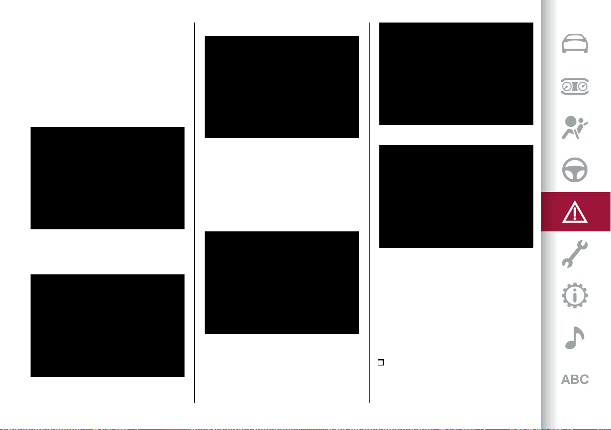
191
REMOTE BATTERY CONNECTION
POLES
To facilitate the operation, the remote
poles of the battery for the jump starting
can be found in the engine compartment:
the battery, on the other hand, is placed
in the luggage compartment.
Thenegativeterminal(-)fig.208 is
located next to the right bonnet catch.
208 08076V0006EM
You can access the positive terminal (+)
by liftingthe protective flapfig. 209.
209 08076V0002EM
Thepoleisshowninfig. 210.
210 08076V0001EM
Quadrifoglio version
Thenegativeterminal(-)fig.211 is
located next to the right bonnet catch.
The positive terminal (+) can be reached
by lifting the protective flap fig. 210 and
isshowninfig.213.
211 08076V0003EM
212 08076V0004EM
213 08076V0005EM
To carry out the operation, you need to
have the correct cables to connect the
auxiliary battery to the remote poles of
the flat battery.
Usually, these cables have terminals at
the ends and are identified by different
sheath colours (red = positive, black =
negative).
JUMP STARTING
193) 194) 195)
Proceed as follows:
switch off all electrical devices in the
car;
IN AN EMERGENCY
192
engage the parking brake, actiate P
(Park) mode and put the starter switch in
the STOP position;
should you be using the battery of
another car, park the other car within
the range of the cables used for the
connection, operate the parking brake
and ensure that its ignition is off.
WARNING If the auxiliary battery is
installed on another vehicle, check that
there is no accidental contact of metal
parts between the two vehicles, since an
earth connection may result, with the risk
of serious injury to any people who may
be nearby.
WARNING If the procedure below is
carried out incorrectly, it can cause
severe injury to people or damage
the recharging system of one or
both vehicles. Carefully follow the
instructions given below.
Cable connection
74)
Proceed as follows to carry out a jump
starting:
connect a terminal on the end of the
positive cable from the remote positive
pole (+) of the car with flat battery;
connect the terminal on the opposite
end of the positive (+) cable to the
positive (+) pole of the auxiliary battery;
connect a negative cable end terminal
to the negative (-) pole of the auxiliary
battery;
connect the terminal on the opposite
end of the negative (-) cable to the earth
point (-) on the car with the battery flat;
start the engine of the car with an
auxiliary battery, let it run for some
minutes at idle and then start the engine
of the car with flat battery.
In case a portable battery is used, before
starting the car, wait a few seconds after
completing the connection.
Cable disconnection
Once the engine is started, remove the
connection cables in reverse sequence,
as shown below:
disconnect the negative cable end
terminal (-) from the earth point (-) of the
car with flat battery;
disconnect the terminal on the
opposite end of the negative cable from
the negative (-) pole of the auxiliary
battery;
disconnect the terminal on the
opposite end of the positive (+) cable
from the positive (+) pole of the auxiliary
battery;
disconnect the terminal on the end
of the positive cable from the remote
positive pole (+) of the car with flat
battery.
WARNING
193) Do not get too close to the radiator
cooling fan: the electric fan may start;
danger of injury. Scarves, ties and other
loose clothing might be pulled by moving
parts.
194) Remove any metal objects (e.g. rings,
watches, bracelets), that might cause an
accidental electrical contact and cause
serious injury.
195) The batteries contain acid that can
burn skin or eyes. Batteries produce
hydrogen, which is easily flammable and
explosive. Thus keep away flames or
devices which may cause sparks.
IMPORTANT
73) Never use a fast battery charger to
start the engine as this could damage the
electronic systems, particularly the engine
ignition and fuel supply control units.
74) Do not connect the cable to the negative
terminal (–) of the flat battery. The following
spark could lead to battery explosion and
cause serious harm. Only use the specific
earth point; do not use any other exposed
metallic part.
193
FUEL CUT-OFF SYSTEM
DESCRIPTION
Depending on the type and violence
of the impact, the control unit of the
ORC occupant protection systems
determines whether to activate
the airbags and the front seat belt
pretensioners and whether to
immediately interrupt the current from
the batteries to the supply pumps and to
the devices that operate the engine. The
power from the battery is interrupted by
"skipping" the pyrotechnic fuse placed on
the fusebox next to the positive pole of
the battery.
When the fuse is "skipped", only some
services, necessary for the safety of the
vehicle (e.g.: door locks, anti-theft device,
etc.), remain powered.
WARNING After the impact, carefully
check the vehicle for fuel leaks, for
instance in the engine compartment,
under the vehicle or near the tank area.
WARNING Contact an Alfa Romeo
Dealership to have the system checked.
AUTOMATIC TRANSMISSION
GEAR LEVER RELEASE
To release the automatic transmission
lever, contact an Alfa Romeo Dealership.
TOWING THE BROKEN-DOWN
CAR
REAR WHEEL DRIVE (RWD) VERSIONS
It is recommended to tow the car with all
four wheels lifted from the ground on the
platform of a roadside assistance car.
If a breakdown truck with platform is not
available, the vehicle must be towed with
the rear wheels LIFTED from the ground
(using a trailer or special equipment
allowing lifting of the rear wheels).
WARNING Towing vehicles without
complying with the above mentioned
prescriptions can cause serious damage
to the vehicle.
ALL-WHEEL DRIVE (AWD) VERSIONS
It is recommended to tow the car with all
four wheels lifted from the ground on the
platform of a roadside assistance car.
WARNING Avoid lifting the front (or rear)
wheels only, using a trailer or vehicle
that allows lifting the wheels of one axle
only. Lifting the front (or rear) wheels
only while towing might damage the
transmission or the transfer unit.
WARNING If a car is towed without
complying with the above requirements,
the transmission and/or the transfer unit
might be seriously damaged. Damage
due to incorrect towing is not covered by
warranty.
TOWING THE CAR
196) 197)
In order to be able to tow the car, which
has been in an accident or has broken
down, on the road surface and only for
short distances, a tow ring is provided
in the tools container inside the luggage
compartment.
Proceed as follows to use the tow hook:
releasethecapfig.214 onthefrontor
rearbumper(where provided) fig.215,
pressing on the upper part;
214 08136V0001EM
IN AN EMERGENCY
194
215 08136V0003EM
take the tow hook from its housing in
the boot and carefully clean the threaded
housing on the vehicle before using it;
tighten the vehicle's tow hook in its
place for about 11 turns.
WARNING The largest work angle of
the cable to fix on the tow ring must not
exceed15°,asshown infig. 216.
216 08136V0002EM
WARNING
196) Move the ignition device to ON and
then to STOP, without opening the door.
197) The brake servo and the
electromechanical power steering will not
work while the vehicle is being towed. You
will therefore need to apply more force on
the brake pedal and steering wheel. Do not
use flexible ropes when towing, and avoid
jerky movements. While towing, make sure
that the trailer hitch does not damage any
components it is touching. When towing the
car, you must comply with all specific traffic
regulations and adopt an appropriate
driving behaviour. Do not start the engine
while towing the car. Before tightening the
ring, clean the threaded housing thoroughly.
Make sure that the ring is fully screwed into
the housing before towing the car.

Correct servicing permits the performance of the car to be
maintained over time, as well as limited running costs and
safeguarding the efficiency of the safety systems.
This chapter explains how.
MAINTENANCE AND CARE
SCHEDULEDSERVICING ...............................................196
ENGINECOMPARTMENT.............................................. 208
RECHARGINGTHEBATTERY .......................................... 215
SERVICINGPROCEDURES .............................................216
RAISINGTHEVEHICLE..................................................218
WHEELSANDTYRES ...................................................218
BODYWORK ..............................................................219
MAINTENANCE AND CARE
196
SCHEDULED SERVICING
Correct servicing is crucial for
guaranteeing a long life for the car under
the best conditions.
For this reason, Alfa Romeo has planned
a series of checks and maintenance
operations at fixed distance intervals
and, for versions/markets, where
provided, at fixed time intervals, as
described in the Service Schedule.
Before each service, it is always
necessary to carefully follow the
instructions in the Scheduled Servicing
Plan (e.g. periodically check level of
fluids, tyre pressure, etc.).
Scheduled Servicing is offered by an Alfa
Romeo Dealership according to a set
time schedule. If, during each operation,
in addition to the ones scheduled, the
need arises for further replacements or
repairs, these may be carried out with
the owner's explicit consent only.
WARNING Scheduled Servicing
interventions are set out by the
Manufacturer. Failure to have them
carried out may invalidate the warranty.
It is advisable to inform the Alfa Romeo
Dealership of any small operating
irregularities without waiting for the next
service.
REGULAR CHECKS
Every year or 620 miles (1,000km) or
before long journeys, check and top up, if
necessary:
engine coolant level;
brake fluid level (if insufficient, see
an Alfa Romeo dealership as soon as
possible);
AdBlue
®
(UREA) diesel emissions
additive (2.2 JTD versions only);
windscreen washer fluid level;
tyre inflation pressure and condition;
operation of lighting system
(headlights, direction indicators, hazard
warning lights, etc.);
operation of windscreen wash/wipe
system and positioning/wear of wiper
blades.
Oil consumption of the engine depends
on conditions and driving style.
For this reason, the engine oil level must
be checked every 1860 miles (3000 km),
and topped up, if necessary (see the
"Engine compartment - Checking the
levels" paragraph for information on the
quantity to be topped up).
DEMANDING USE OF THE CAR
If the vehicle is used in one of the
following conditions:
dusty roads;
short, repeated journeys (less than
4.3-4.9 mi / 7-8 km) at sub-zero outside
temperatures;
engine often idling or driving long
distances at low speeds or long periods
of inactivity;
in the event of a long period of
inactivity;
the following checks must be carried
out more often than indicated in the
Scheduled Servicing Plan:
check front and rear disc brake pad
condition and wear;
check cleanliness of bonnet and
tailgate locks, cleanliness and lubrication
of linkage;
visually inspect conditions of:
engine, gearbox, transmission,
pipes and hoses (exhaust/fuel
system/brakes) and rubber elements
(gaiters/sleeves/bushes, etc.);
check battery charge and battery fluid
level (electrolyte);
visually inspect conditions of the
accessory drive belts;
197
check and, if necessary, replace the
Bad Fuel filter (where provided).
check and, if necessary, change engine
oil and replace oil filter;
check and, if necessary, replace pollen
filter;
check and, if necessary, replace air
cleaner;
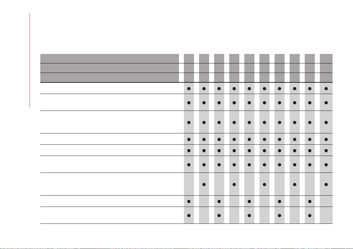
MAINTENANCE AND CARE
198
SCHEDULED SERVICING PROGRAMME (2.9 V6 engine)
WARNING Once you have carried out the last intervention in the table, continue with the scheduled servicing, maintaining the
frequency indicated in the plan by marking each operation with a dot or dedicated note. Warning: simply restarting the maintenance
from the start of the plan may cause the allowed interval to be exceeded for some operations!
Thousands of miles 9 18 27 36 45 54 63 72 81 90
Thousands of kilometres 15 30 45 60 75 90 105 120 135 150
Years 1 2 3 4 5 6 7 8 9 10
Check battery charge status with the proper instrument
Check tyre condition/wear and adjust pressure. Check Tyre Kit
recharge (where provided) conditions/expiry date
Check operation of lighting system (headlights, direction indicators,
hazard warning lights, boot, passenger compartment, glove
compartment, instrument panel warning lights, etc.)
Check and, if necessary, top up fluid levels (1)
Check exhaust emissions/smokiness
Check the supply/engine control and emissions systems operation
using the diagnosis equipment
Visually inspect condition of: exterior bodywork, underbody
protection, pipes and hoses (exhaust, fuel system, brakes), rubber
elements (gaiters, sleeves, bushes, etc.)
Check windscreen and rear window wiper blade position/wear
Check operation of windscreen washer system and adjust jets if
necessary

199
Thousands of miles 9 18 27 36 45 54 63 72 81 90
Thousands of kilometres 15 30 45 60 75 90 105 120 135 150
Years 1 2 3 4 5 6 7 8 9 10
Check cleanliness of bonnet and luggage compartment locks,
cleanliness and lubrication of linkage
Visually inspect conditions and wear of front/rear disc brake pads and
operation of pad wear indicators
Visually inspect the condition and tensioning of the accessory drive
belt(s) (2)
Change engine oil and replace oil filter
Change Transfer Case oil (AWD versions)
Spark plug replacement(3)
Replace accessory drive belt/s (2)
Replace air cleaner cartridge (4)
Change the brake fluid (5)
Replace the Bad Fuel filter (where provided)
Replace passenger compartment cleaner (4)
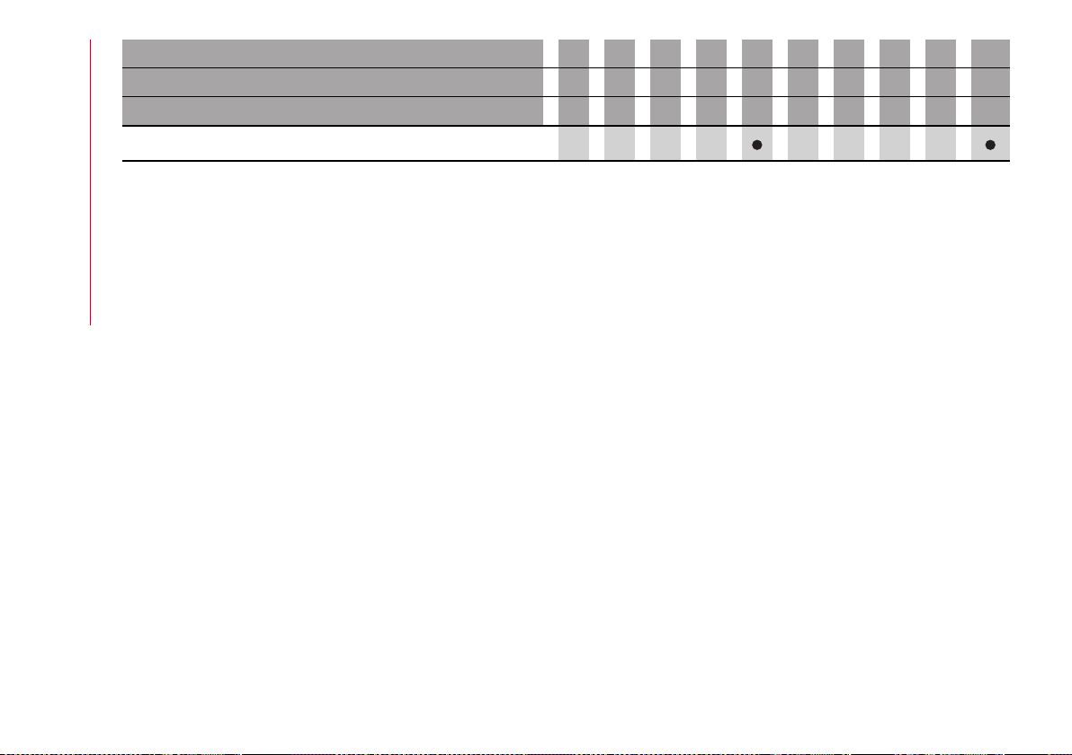
MAINTENANCE AND CARE
200
Thousands of miles 9 18 27 36 45 54 63 72 81 90
Thousands of kilometres 15 30 45 60 75 90 105 120 135 150
Years 1 2 3 4 5 6 7 8 9 10
Alfa Connect Box system battery replacement (where provided) (6)
(1) Always only use the liquids shown in the handbook for topping up after having checked that the system is not damaged.
(2) The maximum mileage is 60,000 km. The belt must be replaced every 4 years, regardless of distance travelled. If the vehicle is used in heavy
conditions (dusty areas, particularly harsh weather conditions, very low or very high temperatures for extended periods, urban driving, long periods
of idling), the maximum mileage is 30,000 km. The belt must be replaced every 2 years regardless of the mileage.
(3) The replacement must be performed according to mileage and regards of the elapsed time. The following are vital in order to ensure correct
operation and prevent serious damage to the engine: - only use spark plugs specifically certified for the engine itself of the same type and brand
(see the "Engine" paragraph in the "Technical specifications" chapter); - strictly comply with the spark plug replacement intervals in the Scheduled
Servicing Plan. It is advisable to contact a reference Dealership for plug replacement.
(4) If the car is used in dusty areas, this cleaner must be replaced every 15,000 km.
(5) The brake fluid must be changed every 2 years, regardless of the mileage.
(6) The battery in the Alfa Connect Box system must be replaced every 5 years, regardless of mileage.
(o) Recommended operations
(●) Mandatory operations
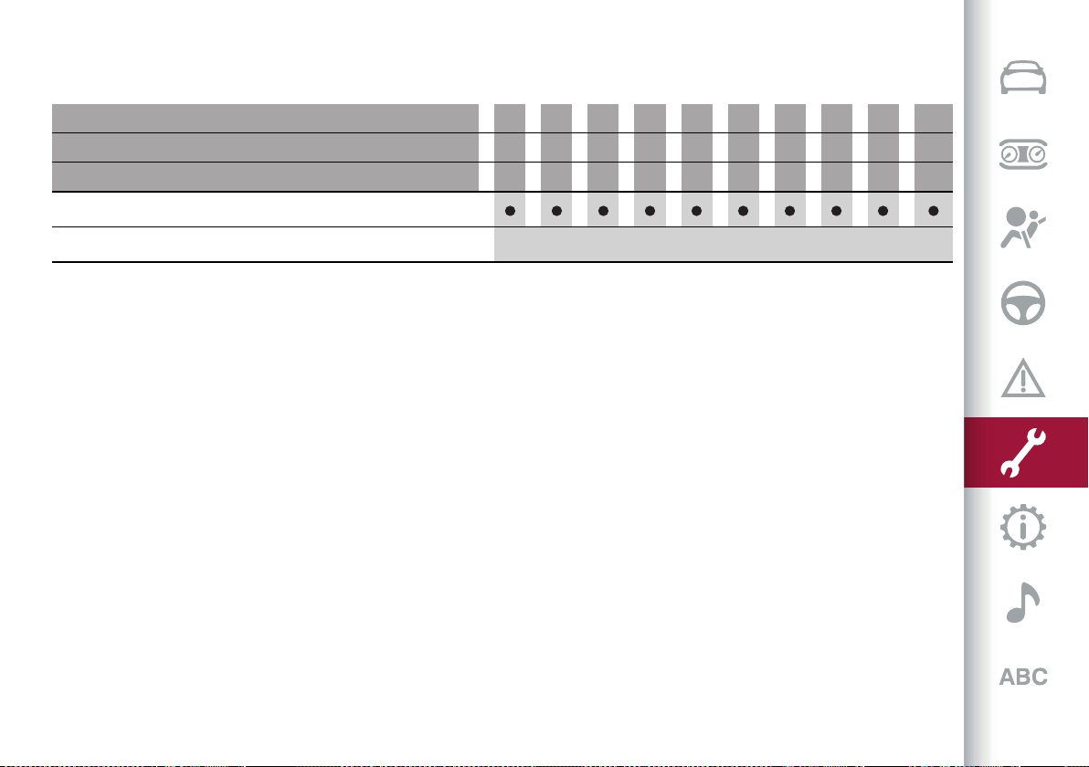
201
FOR VEHICLES EQUIPPED WITH CARBON CERAMIC BRAKE DISCS
Thousands of miles 9 18 27 36 45 54 63 72 81 90
Thousands of kilometres 15 30 45 60 75 90 105 120 135 150
Years 1 2 3 4 5 6 7 8 9 10
Visually inspect the brake discs surface and edge
Brake pads/brake discs replacement (6)
(6) The actual interval for changing the brake pads and the carbon ceramic brake discs depends on the car usage conditions and is signalled by the
warning light or message on the instrument panel. Use the diagnosis equipment to reset the warning light every time the discs are replaced.
(O) Recommended operations
(●) Mandatory operations
MAINTENANCE AND CARE
202
SERVICE SCHEDULE (2.0 T4 MAir petrol engine versions)
WARNING Once you have carried out the last intervention in the table, continue with the scheduled servicing, maintaining the
frequency indicated in the plan by marking each operation with a dot or dedicated note. Warning: simply restarting the maintenance
from the start of the plan may cause the allowed interval to be exceeded for some operations!
Thousands of miles 9 18 27 36 45 54 63 72 81 90
Thousands of kilometres 15 30 45 60 75 90 105 120 135 150
Years 1 2 3 4 5 6 7 8 9 10
Check battery charge status with the proper instrument
Check tyre condition/wear and adjust pressure. Check Tyre Kit
recharge (where provided) conditions/expiry date
Check operation of lighting system (headlights, direction indicators,
hazard warning lights, boot, passenger compartment, glove
compartment, instrument panel warning lights, etc.)
Check and, if necessary, top up fluid levels (1)
Check exhaust emissions/smokiness
Check the supply/engine control and emissions systems operation
using the diagnosis equipment
Check engine oil deterioration using the diagnosis equipment (2)
Visually inspect condition of: exterior bodywork, underbody
protection, pipes and hoses (exhaust, fuel system, brakes), rubber
elements (gaiters, sleeves, bushes, etc.)
Check windscreen and rear window wiper blade position/wear
Check operation of windscreen washer system and adjust jets if
necessary
203
Thousands of miles 9 18 27 36 45 54 63 72 81 90
Thousands of kilometres 15 30 45 60 75 90 105 120 135 150
Years 1 2 3 4 5 6 7 8 9 10
Check cleanliness of bonnet and luggage compartment locks,
cleanliness and lubrication of linkage
Visually inspect conditions and wear of front disc brake pads and
operation of pad wear indicators
Visually inspect conditions and wear of rear disc brake pads and
operation of pad wear indicators
Visually inspect the condition and tensioning of the accessory drive
belt(s) (3)
Change engine oil and replace oil filter (4)
Replace Transfer Case oil (for AWD versions)
Spark plug replacement(5)
Replace accessory drive belt/s (3)
Replace air cleaner cartridge (6)
Change the brake fluid (7)
Replace passenger compartment cleaner (6)

MAINTENANCE AND CARE
204
Thousands of miles 9 18 27 36 45 54 63 72 81 90
Thousands of kilometres 15 30 45 60 75 90 105 120 135 150
Years 1 2 3 4 5 6 7 8 9 10
Alfa Connect Box system battery replacement (where provided) (8)
(1) Only ever use the fluids shown in the handbook for topping up, and only after checking that the system is intact.
(2) If the engine oil quality detected by the vehicle diagnostics is lower than 20%, it is advisable to replace the engine oil and engine filter in order to
avoid another service operation after a short time.
(3) The maximum mileage is 60,000 km. The belt must be replaced every 4 years, regardless of distance travelled. If the vehicle is used in heavy
conditions (dusty areas, particularly harsh weather conditions, very low or very high temperatures for extended periods, urban driving, long periods
of idling), the maximum mileage is 30,000 km. The belt must be replaced every 2 years regardless of the mileage.
(4) The engine oil and filter change interval depends on the driving conditions and is signalled by a warning light or message on the instrument panel.
In any cases, never exceed 1 year.
(5) The replacement must be performed according to mileage and regards of the elapsed time. The following are vital in order to ensure correct
operation and prevent serious damage to the engine: - only use spark plugs specifically certified for the engine itself of the same type and brand
(see the "Engine" paragraph in the "Technical specifications" chapter); - strictly comply with the spark plug replacement intervals in the Scheduled
Servicing Plan. It is advisable to contact a reference Dealership for plug replacement.
(6) If the car is used in dusty areas, this cleaner must be replaced every 15,000 km.
(7) The brake fluid must be changed every 2 years, regardless of the mileage.
(8) The battery in the Alfa Connect Box system must be replaced every 5 years, regardless of mileage.
(o) Recommended operations
(●) Mandatory operations
205
SCHEDULED SERVICING PLAN (2.2 JTD diesel engine versions)
WARNING Once you have carried out the last intervention in the table, continue with the scheduled servicing, maintaining the
frequency indicated in the plan by marking each operation with a dot or dedicated note. Warning: simply restarting the maintenance
from the start of the plan may cause the allowed interval to be exceeded for some operations!
Thousands of miles 12 24 36 48 60 72 84 96 108 120
Thousands of kilometres 20 40 60 80 100 120 140 160 180 200
Years 1 2 3 4 5 6 7 8 9 10
Check battery charge status with the proper instrument
Check tyre condition/wear and adjust pressure. Check the Tyre Repair
Kit recharge (where provided) conditions/expiry date
Check operation of lighting system (headlights, direction indicators,
hazard warning lights, boot, passenger compartment, glove
compartment, instrument panel warning lights, etc.)
Check and, if necessary, top up fluid levels in engine compartment
(engine coolant, hydraulic clutch/brakes, windscreen washer, battery,
etc.) (1) (2)
Check exhaust emissions/smokiness
Use the diagnosis socket to check supply/engine management
systems operation, emissions and, for versions/markets, where
provided, engine oil degradation (3)
Visually inspect condition of: exterior bodywork, underbody
protection, pipes and hoses (exhaust, fuel system, brakes), rubber
elements (gaiters, sleeves, bushes, etc.)
Check windscreen and rear window wiper blade position/wear

MAINTENANCE AND CARE
206
Thousands of miles 12 24 36 48 60 72 84 96 108 120
Thousands of kilometres 20 40 60 80 100 120 140 160 180 200
Years 1 2 3 4 5 6 7 8 9 10
Check operation of windscreen washer system and adjust jets if
necessary
Check cleanliness of bonnet and luggage compartment locks,
cleanliness and lubrication of linkage
Visually inspect conditions and wear of front disc brake pads and
operation of pad wear indicators
Visually inspect conditions and wear of rear disc brake pads and
operation of pad wear indicators
Visually inspect the condition and tensioning of the accessory drive
belt(s) (4)
Visually inspect the toothed timing drive belt (4)
Change engine oil and replace oil filter (5)
Replace Transfer Case oil (for AWD versions)
Replace accessory drive belt/s (4)
Replace toothed timing drive belt (4)
Replace air cleaner cartridge (6)
Replace fuel filter cartridge (7)
Change the brake fluid (8)
Replace the passenger compartment cleaner
207
Thousands of miles 12 24 36 48 60 72 84 96 108 120
Thousands of kilometres 20 40 60 80 100 120 140 160 180 200
Years 1 2 3 4 5 6 7 8 9 10
Alfa Connect Box system battery replacement (where provided) (9)
(1) Only ever use the fluids shown in the handbook for topping up, and only after checking that the system is intact.
(2) The consumption of AdBlue
®
(UREA) emissions additive depends on the conditions of use of the car and is indicated by means of the symbol and
a specific message on the instrument panel display.
(3) If the engine oil quality detected by the vehicle diagnostics is lower than 20%, it is advisable to replace the engine oil and engine filter in order to
avoid another service operation after a short time.
(5) The actual interval for changing engine oil and replacing the engine oil filter depends on the car usage conditions and is signalled by the warning
light or message on the instrument panel. In any case, it must never exceed 2 years. Where the car is used mostly in urban settings you need to
replace the engine oil filter every year.
(4) The maximum mileage is 120,000 km. The belt must be replaced every 5 years, regardless of distance travelled. If the vehicle is used in heavy
conditions (dusty areas, particularly harsh weather conditions, very low or very high temperatures for extended periods, urban driving, long periods
of idling), the maximum mileage is 60,000 km. The belt must be replaced every 4 years regardless of the mileage.
(6) If the vehicle is used in dusty areas, this cleaner should be replaced every 20,000 km.
(7) If the car runs on fuel with quality below the relevant European specification, this filter must be replaced every 20,000 km
(8) The brake fluid must be changed every 2 years, regardless of the mileage.
(9) The battery in the Alfa Connect Box system must be replaced every 5 years, regardless of mileage.
(o) Recommended operations
(●) Mandatory operations

MAINTENANCE AND CARE
208
ENGINE COMPARTMENT
CHECKING LEVELS
198) 199)
75)
2.9 V6 Engine
217 09016V0001EM
1. Engine oil filler / 2. Primary engine cooling reservoir plug / 3. Brake fluid reservoir plug access cover / 4. Windscreen/headlight
washer fluid reservoir cap 5. Secondary engine cooling reservoir plug

209
2.0 T4 MAir engine
218 09026V0002EM
1. Engine oil filler / 2. Primary engine cooling reservoir plug / 3. Brake fluid reservoir plug access cover / 4. Windscreen/headlight
washer fluid reservoir cap 5. Secondary engine cooling reservoir plug

MAINTENANCE AND CARE
210
2.2 JTD Engine
219 09026V0020EM
1. Engine oil filler / 2. Primary engine cooling reservoir plug / 3. Brake fluid reservoir plug access cover / 4. Windscreen/headlight
washer fluid reservoir cap 5. Secondary engine cooling reservoir plug
211
IMPORTANT
75) Be careful not to confuse the various types of fluids while topping up: they are not compatible with one another! Topping up with an unsuitable
fluid could severely damage your vehicle.
WARNING
198) Never smoke while working in the engine compartment: gas and inflammable vapours may be present, with the risk of fire.
199) Be very careful when working in the engine compartment when the engine is hot: you may get burned. Do not get too close to the radiator
cooling fan: the electric fan may start; danger of injury. Scarves, ties and other loose clothing might be pulled by moving parts.

MAINTENANCE AND CARE
212
ENGINE OIL
200)
76)
WARNING It is advisable to check the oil
level indication before long journeys.
The engine oil level can be seen on the
instrument panel display every time the
engine is started, or on the Connect
system display using the "Vehicle
Information" widget.
Use the 6 segments on the display to
check that the oil level is between MIN
and MAX level: 1 segment = MIN level,
6 segments = MAX level. If the oil level
indication reaches the first red mark,
add oil through the filler 1, considering
that each notch shown on the display
corresponds to approximately:
2.9 V6 Engine
0.055 UK gal (250 ml)
2.0 T4 MAir engine
0.055 UK gal (250 ml)
2.2 JTD Engine
0.053 UK gal (200 ml)
If the symbol and the corresponding
indication "Insufficient engine oil level"
light up on the display, top up 1 litre of oil
as soon as possible.
77)
WARNING Make sure not to add too
much engine oil when topping up. Engine
oil in excess may damage the engine.
Have the car checked. Never exceed the
MAX level when topping up engine oil.
It is advisable to check the oil level in
intermediate steps on the instrument
panel display. Use the oil dipstick on the
Quadrifoglio version to check the level.
2.9 V6 engine: If the level is over the MAX
line on the dipstick, go to a dedicated
Alfa Romeo Dealership.
WARNING The oil level is not refreshed
immediately on the display of the
instrument panel after topping up.
Consequently, wait for the oil level to
be refreshed on the display following to
procedure shown below.
Oil level indication update on display
If a top-up is needed, proceed as follows
to ensure correct indication of the oil
level on the display:
2.9 V6 Engine
Proceed as follows:
with the car level, run the engine for
approximately 5 minutes (temperature
of approximately 194°F/ 90°C) and then
stop the engine;
wait for at least 5 minutes, turn the
ignition switch in ON position without
starting the engine and wait for a few
seconds.
If the level indication is not updated after
the previously described procedure,
repeat the engine adjustment, stop the
engine and wait a further 5 minutes
before starting it again. If the indication
is not updated after the second start,
contact the dedicated Alfa Romeo
Dealership.
WARNING In normal working conditions,
the oil level indication is shown on the
instrument panel display. In case of oil
level sensor failure (condition indicated
by the lighting of the symbol on the
instrument panel display), use the oil
dipstick in the engine compartment
EXCLUSIVELY for the time needed to
restore correct operation of the oil level
sensor. The latter operation must be
performed at a dedicated Alfa Romeo
Dealership.
2.0 T4 MAir engine
Proceed as follows:
with the car level, run the engine for
approximately 5 minutes (temperature
higher than 176°F/ 80°C) and then stop
the engine;
start the engine again and idle it for
about 2 minutes.
2.2 JTD Engine
Proceed as follows:
with the car level, run the engine until
the third oil temperature notch lights on
the display on the instrument panel, then
stop the engine;
213
wait for at least 3 minutes, turn the
ignition switch in ON position without
starting the engine and wait for 20
seconds.
Procedure for reading the engine oil level
with the engine running and idling
Proceed as follows:
with the car stopped, parked on level
ground, run the engine until the second
oil temperature notch lights on the
display on the instrument panel;
idle the engine and wait at least 1
minute for the correct reading.
WARNING If the indication is not correct
after the procedure, contact an Alfa
Romeo Dealership.
WARNING The oil dipstick in the engine
compartment, on versions with 2.2 JTD
engine, must be used ONLY if the oil level
sensor is faulty. The latter condition is
indicated by the symbol which will
appear on the instrument panel.
The manual engine oil level checking
procedure must be carried out, when
necessary, on a cold engine only.
Never attempt to carry out the manual
engine oil checking procedure (using the
dipstick) with the engine hot. Contact
with the surrounding hot engine parts
could cause burns.
This operation is permitted only for the
time actually needed to restore correct
operation of the oil level sensor at an
Alfa Romeo dealership.
Engine oil consumption
78)
4)
The maximum engine oil consumption
is usually 0.88 lb (400 grams every
620 miles (1000 km). When the car is new,
the engine needs to be run in, therefore
the engine oil consumption can only be
considered stabilised after the first 3100
- 3700 miles (5000 - 6000 km).
ENGINE COOLANT
201)
79)
If the level is below the MIN mark,
remove the reservoir cap and top up
with suitable fluid (see the "Fluids and
lubricants" paragraph in the "Technical
data" chapter), until it reaches the MAX
mark.
WARNING Never attempt to remove the
cap with radiator or expansion tank hot:
DANGER OF SCALDING!
WINDSCREEN/HEADLIGHT WASHER
FLUID
202) 203)
The windscreen and headlights washer
fluid reservoir (where available) is
equipped with a telescopic filler.
If the level is low, remove the reservoir
cap (4) fig.220 andthen liftthefiller,
as shown in the figure, and add the
fluid described in the "Technical
Specifications" chapter. After having
topped up the fluid, arrange the filler
correctly and then press on the cap until
you hear it click.
220 09086S0666EM
NOTE The headlight washers are
activated every 10 activations of the
windscreen washer.
WARNING With a low fluid level
(indicated by the dedicated symbol
appearing on the instrument panel
MAINTENANCE AND CARE
214
display), the headlight washer system
does not work, even though the screen
washers continue to work.
BRAKE FLUID
Check that the fluid is at the max. level. If
the liquid level in the tank is insufficient,
contact an Alfa Romeo Dealership to
have the system checked.
AUTOMATIC TRANSMISSION
ACTIVATION SYSTEM OIL
5)
The transmission control oil level should
only be checked at an Alfa Romeo
Dealership.
BATTERY
204) 205) 206) 207)
6)
The battery does not require the
electrolyte to be topped up with distilled
water. A periodic check carried out at
an Alfa Romeo Dealership is, however,
necessary to check efficiency.
Follow the battery manufacturer's
instructions for maintenance.
Useful advice for extending the life of
your battery
To avoid draining your battery and make
it last longer, observe the following
instructions:
when you park the car, ensure that the
doors, tailgate and bonnet are closed
properly, to prevent any lights from
remaining on inside the passenger's
compartment;
switch off all roof lights inside the
car: the car is however equipped with a
system which switches all internal lights
off automatically;
do not keep accessories (e.g. Connect
system, hazard warning lights, etc.)
switched on for a long time when the
engine is not running;
before performing any operation on
the electrical system, disconnect the
negative battery cable.
If, after purchasing the car, you wish
to install electrical accessories
which require permanent electrical
supply (e.g. alarm, etc.) or accessories
which influence the electrical supply
requirements, contact an Alfa Romeo
Dealership, whose qualified staff
will evaluate the overall electrical
consumption.
WARNING If the battery was
disconnected, do not start the engine
immediately after reconnecting the
terminals, but press the start button,
without operating the pedals, to turn on
the instrument panel and then start the
engine.
WARNING If the charge level remains
under 50% for a long time, the battery
is damaged by sulphation, reducing its
capacity and efficiency at start-up. The
battery is also more prone to the risk
of freezing (at temperatures of 14°F / -
10°C).
Replacing the battery
If necessary, replace the battery with
another original battery with the same
specifications. Follow the battery
Manufacturer’s instructions for
maintenance.
WARNING
200) If the engine oil is being topped up,
wait for the engine to cool down before
loosening the filler cap, particularly for
vehicles with aluminium cap (where
provided). WARNING: risk of burns!
201) The cooling system is pressurised.
If necessary, only replace the plug with
another original or the operation of the
system may be adversely affected. Do not
remove the reservoir plug when the engine is
hot: you risk scalding yourself.
202) Do not travel with the windscreen
washer fluid reservoir empty: the
windscreen washer is essential for
improving visibility. Repeated operation of
the system without fluid could damage or
cause rapid deterioration of some system
components.
203) Some commercial additives for
windscreen washer fluid are flammable.
The engine compartment contains hot
components which may start a fire.
215
204) Battery fluid is poisonous and
corrosive. Avoid contact with the skin and
eyes. Keep open flames away from the
battery and do not use objects that might
create sparks: risk of explosion and fire.
205) Using the battery with low fluid will
irreparably damage the battery and may
cause an explosion.
206) If the car must remain unused for a
long time at a very low temperature, remove
the battery and take it to a warm place, to
avoid freezing.
207) Always wear appropriate goggles to
protect your eyes when working on or near
the battery.
IMPORTANT
76) The oil level must never exceed the MAX
mark.
77) If the MAX mark is exceeded (last notch
on the right turns red) after the top-up, go
to an Alfa Romeo Dealership as soon as
possible to have the oil in excess removed.
78) Always top up using engine oil of the
same specifications as that already in the
engine.
79) Use a fluid of the same type as that
already present in the reservoir for any
topping up of the engine cooling system.
The fluid cannot be mixed with other types
of antifreeze fluids. In the event of topping
up with an unsuitable product, under no
circumstances start the engine and contact
an Alfa Romeo Dealership.
IMPORTANT
4) Used engine oil and oil filters contain
substances which are harmful to the
environment. To change the oil and filters,
we advise you to contact an Alfa Romeo
Dealership.
5) Used transmission oil contains
substances that may be dangerous for the
environment. You are advised to contact an
Alfa Romeo Dealership for oil changes.
6) Batteries contain substances which
are very harmful for the environment.
For battery replacement, contact an Alfa
Romeo Dealership.
RECHARGING THE BATTERY
IMPORTANT NOTES
208) 209)
WARNING Before using the charging
device, always make sure that it is
appropriate for the installed battery,
with constant voltage (below 14.8 V) and
low amperage (maximum 15 A).
WARNING Recharge the battery in a well
ventilated environment.
WARNING Never charge or recharge a
frozen battery: it may explode because
of the hydrogen trapped inside the ice
crystals.
WARNING At all times while charging
or recharging the battery, make sure
that any sparks or open flames are kept
sufficiently far away from the battery.
WARNING Before using any devices to
charge or to maintain the charge of the
battery, carefully follow the instructions
provided with the device in order to
properly and safely connect it to the car
battery.
You can recharge the battery without
disconnecting the wires of the electrical
system of the car.
To reach the battery, remove the
load platform inside the luggage
compartment fig. 221;
221 04206V0004EM
removethe accesscoverfig.222;
MAINTENANCE AND CARE
216
222 09036V0005EM
removethe protectivecover(1) fig.223
and connect the positive cable terminal
of the charger (usually red) to the
positive terminal (+) of the battery;
connect the terminal of the negative
cable of the charger (usually black) to nut
(2) next to the negative terminal (-) of the
battery, asshowninfig.223;
223 09036V0002EM
The car is equipped with an IBS
(Intelligent Battery Sensor), which is able
to measure the charge and discharge
voltage and calculate the charge level
and the general condition of the battery.
The sensor is placed next to the negative
terminal (-) of the battery.
For a correct charge/discharge
procedure, the charge voltage must go
through the IBS sensor.
Turn the charger on and follow the
instructions on the user's manual to
completely recharge the battery;
when the battery is charged, turn the
charger off before disconnecting it from
the battery;
first disconnect the black cable
terminal of the battery charger and then
the red cable terminal;
refit the protective cover of the
positive terminal of the battery
and the access cover to the battery
compartment.
WARNING If a "quick-type" battery
charger is used with the battery fitted
on the vehicle, before connecting it
disconnect both cables of the battery
itself. Do not use a "quick-type" battery
charger to provide the starting voltage.
WARNING
208) The process of charging or recharging
the battery produces hydrogen, a
flammable gas that can explode and cause
serious injury.
209) When charging or recharging the
battery, always follow the precautions
listed.
SERVICING PROCEDURES
210) 211) 212)
80) 81) 82) 83) 84) 85) 86)
AIR CONDITIONING SYSTEM
MAINTENANCE
86) 87)
To ensure the best possible
performance, the air conditioning
system must be checked and undergo
maintenance at an Alfa Romeo
Dealership at the beginning of the
summer.
WINDSCREEN WIPER
Raising the windscreen wiper blades
("Service position" function)
The "Service position" function allows
the driver to replace the windscreen
wiper blades more easily. It is also
recommended to activate this function
when it is snowing and to make it easier
to remove any dirt deposits in the
area where the blades are normally
positioned, when washing.
217
To activate this function, deactivate the
windscreen wiper (ringfig. 224in position
O) before setting the ignition device to
STOP.
This function can only be activated within
2 minutes of setting the ignition device
to STOP.
To activate this function, move the lever
upwards (unstable position) for at least
three seconds.
224 09046V0001EM
If, after using the function, the ignition
device is set back to ON with the blades
in a position other than rest position (at
the base of the windscreen), they will
only return to rest position following a
command given using the stalk (stalk
upwards, into unstable position) or when
a speed of 3 mph (5 km/h) is exceeded.
Replacing the windscreen/rear window
wiper blades
Proceed as follows:
raise the wiperarm,press tab,fig. 225,
of the attachment spring and remove the
blade from the arm;
225 09046V0002EM
fit the new blade, inserting the tab in
the dedicated housing in the arm and
checking that it is locked;
lower the wiper arm onto the
windscreen.
WARNING Do not operate the
windscreen wiper with the blades lifted
from the windscreen.
Windscreen/rear window washer
The screen washer jets are located on
the windscreen wiper arms, the rear
screen wiper arm and the rear spoiler.
If there is no jet of fluid, firstly check
that there is fluid in the reservoir (see
paragraph “Engine compartment” in this
chapter).
Then check that the nozzle holes are not
clogged; use a needle to unblock them if
necessary.
WARNING
210) The air intake system (air cleaner,
rubber hoses, etc.) can be a protection in
the case of blowbacks from the engine. DO
NOT REMOVE this system unless you need
to carry out repair or maintenance. Before
starting the engine, ensure that the system
has not been removed: failure to observe
this precaution may result in serious injury.
211) Exhaust emissions are very dangerous,
and may be lethal. They contain carbon
monoxide, a colourless, odourless gas which
can cause fainting and poisoning if inhaled.
212) The exhaust system may reach high
temperatures and may cause a fire if the
car is parked on flammable material. Dry
grass or leaves can also catch fire if they
come into contact with the exhaust system.
Do not park or use the car in a place in which
the exhaust system might come into contact
with flammable material.
IMPORTANT
80) Incorrect servicing of the car or failure
to carry out operations or repairs (when
necessary) may lead to more expensive
repairs, damage to other components
or have a negative impact on the car
performance. Have any malfunction
inspected immediately by an Alfa Romeo
Dealership.
81) The car is filled with fluids which are
optimised or protecting its performance
and life and extending service intervals.
Do not use chemicals for washing these
components since they may damage the
Activation of the function
MAINTENANCE AND CARE
218
engine, the transmission or the climate
control system. This damage is not covered
by the car’s warranty. If any component
needs to be washed due to malfunctioning,
use only the specific liquid for that
procedure.
82) An excessive or insufficient amount of
oil inside the base is extremely damaging
to the engine. Make sure it is always at an
adequate level.
83) Vehicles equipped with catalytic
converter must be fuelled only with
unleaded petrol. Leaded petrol would
permanently damage the catalytic
converter and eliminate its ability to reduce
polluting emissions, seriously compromising
the engine performance, which would be
irreparably damaged. If the engine does
not work correctly, especially if it starts
irregularly or if there is a reduction of
its performance, immediately go to an
Alfa Romeo Dealership. Prolonged and
faulty operation of the engine may cause
overheating of the converter and, as a
consequence, possible damage to the
converter and the car.
84) Using transmission fluid different from
that approved may compromise the quality
of gear changes and/or cause vibration of
the transmission.
85) It is recommended to have the car
serviced by an Alfa Romeo Dealership.
When carrying out normal periodic
operations and small servicing interventions
personally on the car, it is recommended
to use suitable equipment, genuine spare
parts and the necessary fluids. Do not carry
out any interventions if you do not have the
necessary experience.
86) Always require the use of only
compressor coolants and lubricants
approved and suitable for the specific air
conditioning system fitted on the car. Some
non-approved coolants are flammable and
may explode, with the risk of injuries. The
use of non-approved coolants or lubricants
may adversely affect system efficiency,
leading to expensive repairs.
87) The air conditioner system contains
coolant under high pressure: to avoid
injuries to people or damage to the system,
any coolant addition or repair that requires
to disconnect the cables must be carried out
by an Alfa Romeo Dealership.
RAISING THE VEHICLE
If the car needs to be jacked up, go to
an Alfa Romeo Dealership which is
equipped with shop jacks or jack arms.
The vehicle lifting points are marked on
the side skirts with the symbols (see
illustrationin fig. 226).
226 09056V0001EM
WHEELS AND TYRES
213) 214) 215)
Before embarking on a long trip, and
every two weeks, check the tyre inflation
pressure. Check the tyres when cold.
SNOW CHAINS
88)
Rear Wheel Drive and All-wheel drive
versions
It is possible to fit 0.5 in (13 mm) chains
on all the tyres except for R20.
Quadrifoglio version
It is possible to put chains on the rear
285/40 R20 tyre (winter tyre size).
Avoid using traditional chains as
they can damage the braking system
if not installed correctly, thereby
compromising the car’s safety.
We strongly advise using zero-clearance
chains and to use equipment proposed
by the Dedicated Alfa Romeo Dealership.
Important notes
The use of snow chains should be in
compliance with local regulations of
each country. In certain countries, tyres
marked with code M+S (Mud and Snow)
are considered as winter equipment;
therefore their use is equivalent to that
of the snow chains.
219
WARNING The snow chains may be
applied only to the rear wheel tyres.
Installing them on the rear wheel tyres
could damage the suspension and
transmission.
Check the tension of the snow chains
after the first few metres have been
driven.
WARNING Using snow chains with
tyres with non-original dimensions may
damage the vehicle.
WARNING Using different size or
type (M+S, snow, etc.) tyres between
front and rear axle may adversely
affect car driveability, with the risk of
losing control of the car and resulting
accidents.
SUGGESTIONS ABOUT THE ROTATION
OF THE TYRES
The front and rear tyres are subject
to different loads and stress due to
steering, manoeuvres and braking. For
this reason they are subject to uneven
wear.
To resolve this problem, tyres should
be rotated at the appropriate time
(6200 / 9300 miles / 10000 / 15000 km).
Inverting the tyres means moving them
to different positions on the same side of
the car (front to back and vice versa).
WARNING Crossing the tyres is not
advised, so placing a tyre on a different
axle on the other side of the car is
impossible.
WARNING On cars equipped with
differentiated tyres (tyre size different
between front and rear axles, ex. QV
version) rotation of any of the tyres is
not advised.
Tyre rotation contributes to the
preservation of the grip and traction
performance on wet, muddy or snowy
roads, guaranteeing optimal driveability
of the vehicle.
In the case of irregular wear of the tyres
identify the cause and correct it as soon
as possible, by contacting an Alfa Romeo
Dealership.
WARNING
213) The road holding qualities of the
car also depend on the correct inflation
pressure of the tyres.
214) If tyre pressure is too low, it may
overheat and be severely damaged as a
result.
215) Do not repaint alloy wheel rims at
temperatures higher than 150°C. The
mechanical features of the wheels could be
compromised.
IMPORTANT
88) Keep your speed down when snow
chains are fitted; do not exceed 50 km/h (or
the equivalent in miles). Avoid potholes, do
not drive over steps or pavements and do
not drive long distances over roads without
snow, to avoid damaging both your vehicle
and the road surface.
BODYWORK
PRESERVING THE BODYWORK
Paintwork
89) 7)
Touch up abrasions and scratches
immediately to prevent the formation of
rust.
Some parts of the car may be covered
with a matt paint which, in order to be
maintained intact, requires special care:
see the instructions in the warning at the
end of this paragraph.
90)
To correctly wash the vehicle, follow
these instructions:
if high pressure jets or cleaners are
used to wash the vehicle, hold at least
16 in (40 cm) away from the bodywork to
avoid damage or alteration. Build up of
MAINTENANCE AND CARE
220
water could cause damage to the car in
the long term;
to make it easier to remove any dirt
deposits in the area where the blades are
normally located it is recommended to
position the windscreen wipers vertically
(service position), for more information
consult the “Servicing procedures”
paragraph in this chapter.
If you want to wash a car with automatic
transmission in a car wash that moves it,
you must do the following:
make sure that the car is on a flat
surface and that automatic engagement
of the parking brake when the engine
is switched off is disabled (for how to
disable it, refer to the “Electric parking
brake” section in the “Starting and
driving” chapter);
with the car stationary, the gear in N
(Neutral) and the brake pedal up: press
the start button. The car will remain in
N (Neutral) for 15 minutes, after which P
(Park) mode will be activated.
ENGINE COMPARTMENT WASHING
91)
If the engine compartment is washed (at
low pressure, e.g. in very dusty areas),
this must be done with the engine cold
and with ignition device turned to STOP.
Take care not to direct the water
jet straight at the electronic control
modules or the wiper motors. Have this
operation performed by a specialised
workshop. After washing, check that the
various protective components (e.g.
rubber guards and caps) have not been
removed or damaged.
IMPORTANT
89) In order to preserve the appearance of
the paint abrasive products and/or polishes
should not be used for cleaning the car.
90) Avoid washing with rollers and/or
brushes in washing stations. Wash the car
only by hand using neutral pH detergents;
dry it with a wet chamois leather. Abrasive
products and/or polishes should not be used
for cleaning the car. Bird droppings must be
washed off immediately and thoroughly
as the acid they contain is particularly
aggressive. Avoid (if at all possible) parking
the car under trees; remove vegetable
resins immediately as, when dried, it may
only be possible to remove them with
abrasive products and/or polishes, which is
highly inadvisable as they could alter the
typical opacity of the paint. Do not use pure
windscreen washer fluid for cleaning the
front windscreen and rear window; dilute it
min. 50% with water. Only use pure screen
washer fluid when strictly necessary due to
outside temperature conditions.
91) A high pressure jet cleaner should
not be used for cleaning the engine
compartment. The appropriate precautions
have been taken to protect all parts and
connections, but the pressures generated by
these devices are so high that complete
protection against water seepages cannot
be guaranteed.
IMPORTANT
7) Detergents pollute the water. The vehicle
should be washed in areas equipped for
collecting and purifying the liquid used in the
washing process.

Everything you may find useful for understanding how your
vehicle is made and works is contained in this chapter and
illustrated with data, tables and graphics.
For the enthusiasts and the technician, but also just for those
who want to know every detail of their car.
TECHNICAL SPECIFICATIONS
IDENTIFICATIONDATA .................................................224
ENGINE....................................................................225
RIMSANDTYRES........................................................229
DIMENSIONS ............................................................. 233
WEIGHTS .................................................................235
REFUELLING .............................................................238
FLUIDSANDLUBRICANTS ............................................ 242
PERFORMANCE......................................................... 246
FUELCONSUMPTIONANDCO2EMISSIONS ........................247
PRESCRIPTIONS FOR HANDLING THE CAR AT THE END OF
ITSLIFE .................................................................. 248
TECHNICAL SPECIFICATIONS
222
IDENTIFICATION DATA
VEHICLE IDENTIFICATION NUMBER
The Vehicle Identification Number (VIN)
is stamped on a plate on the front left
corner ofthe dashboardcoverfig.227,
which can be seen from outside the
vehicle, through the windscreen.
227 10016V0001EM
This number is also printed on the
chassis at the front right shock absorber
and can be seen by opening the bonnet
fig. 228.
228 10016V0002EM
VEHICLE IDENTIFICATION NUMBER
(VIN) PLATE
The plate is located on the left side front
doorpillarfig. 229 andshows thedata
about:
(1): correct value of smoke coefficient
(for diesel engines);
(2): name of the manufacturer, car
type-approval number, car identification
number, max. permitted weights;
(3): engine identification, type variant
version, spare part number, colour code,
additional information.
229 10016V0003EM

223
ENGINE
2.9 V6
Cycle Otto
Number and position of cylinders 6 a V
Piston bore and stroke (mm) 86.5 × 82
Total displacement (cm³) 2891
Compression ratio 9.3:1
Maximum power (ECE) (kW) 375
Maximum power (ECE) (HP) 510
Corresponding engine speed (rpm) 6500
Maximum torque (ECE) (Nm) 600
Maximum torque (ECE) (kgm) 61
Corresponding engine speed (rpm) 2500
Spark plugs NGK LKAR8APTJDS
Fuel
Unleaded petrol with RON no lower than 91
(EN228 specifications) (*)
(*) In order to comply with all emission limits while simultaneously guaranteeing minimal consumption and maximum performance, use premium
unleaded petrol with octane rating (R.O.N.) 98 or more.
TECHNICAL SPECIFICATIONS
224
2.0 T4 MAir 200 HP 280 HP
Cycle Otto Otto
Number and position of cylinders 4 in line 4 in line
Piston bore and stroke (mm) 84 / 90 84 / 90
Total displacement (cm³) 1995 1995
Compression ratio 10 ± 0.35 10 ± 0.35
Maximum power (ECE) (kW) 148 206
Maximum power (ECE) (HP) 200 280
Corresponding engine speed (rpm) 4500 5250
Maximum torque (ECE) (Nm) 330 400
Maximum torque (ECE) (kgm) 33.6 40.8
Corresponding engine speed (rpm) 1750 2250
Spark plugs NGK ILZKR7G
Fuel
Unleaded petrol with RON no lower than 91
(EN228 specifications)

225
2.2 JTD 150 HP (*) 180 HP (*)
Cycle Diesel Diesel
Number and position of cylinders 4 in line 4 in line
Piston bore and stroke (mm) 83 / 99 83 / 99
Total displacement (cm³) 2143 2143
Compression ratio 15.5 ± 0.4 15.5 ± 0.4
Maximum power (ECE) (kW) 110 132
Maximum power (ECE) (HP) 150 180
Corresponding engine speed (rpm) 4250 3750
Maximum torque (ECE) (Nm) 450 450
Maximum torque (ECE) (kgm) 45.9 45.9
Corresponding engine speed (rpm) 1750 1750
Fuel Automotive diesel fuel (EN590 and EN16734 specifications)
(*) For versions/markets where provided

TECHNICAL SPECIFICATIONS
226
2.2 JTD 160 HP 190 HP 210 HP
Cycle Diesel Diesel Diesel
Number and position of cylinders 4 in line 4 in line 4 in line
Piston bore and stroke (mm) 83 / 99 83 / 99 83 / 99
Total displacement (cm³) 2143 2143 2143
Compression ratio 15.5 ± 0.4 15.5 ± 0.4 15.5 ± 0.4
Maximum power (ECE) (kW) 118 140 154
Maximum power (ECE) (HP) 160 190 210
Corresponding engine speed (rpm) 3750 3500 3500
Maximum torque (ECE) (Nm) 450 450 470
Maximum torque (ECE) (kgm) 45.9 45.9 47.9
Corresponding engine speed (rpm) 1750 1750 1750
Fuel Automotive diesel fuel (EN590 and EN16734 specifications)
227
RIMS AND TYRES
Alloy rims. Tubeless radial carcass tyres.
All approved tyres are listed in the
registration document.
WARNING If there are any discrepancies
between the Owner Handbook and
the Registration Document, take the
information from the latter. For safe
driving, the car must be fitted with tyres
of the same make and type on all wheels.
WARNING Do not use air chambers with
tubeless tyres.
WARNING Using tyres of a different
size, type, brand or design at the front
and rear may adversely affect car
driveability. We recommend using tyres
approved by the manufacturer. The
manufacturer cannot determine if
unapproved tyres are suitable for use
and therefore cannot guarantee vehicle
safety in those conditions.
CORRECT READING OF THE TYRE
Examplefig.230:215/65R16 98H
230 10096S0001EM
215 Nominal width (S, distance in mm
between sides)
65 Height/width ratio (H/S), expressed
as a percentage
R Radial tyre
16 Rim diameter in inches (Ø)
98 Load rating (capacity)
H Maximum speed rating
Maximum speed index
Q up to 160 km/h
R up to 170 km/h
S up to 180 km/h
T up to 190 km/h
U up to 200 km/h
H up to 210 km/h
V up to 240 km/h
W up to 270 km/h
Y up to 300 km/h
Maximum speed index for snow tyres
QM+S up to 160 km/h
TM+S up to 190 km/h
HM+S up to 210 km/h
Load index (capacity) (*)
60= 250 kg 80= 450 kg
61= 257 kg 81= 462 kg
62= 265 kg 82= 475 kg
63= 272 kg 83= 487 kg
64= 280 kg 84= 500 kg
65= 290 kg 85= 515 kg
66= 300 kg 86= 530 kg
67= 307 kg 87= 545 kg
68= 315 kg 88= 560 kg
69= 325 kg 89= 580 kg
70= 335 kg 90= 600 kg
71= 345 kg 91= 615 kg
72= 355 kg 92= 630 kg
73= 365 kg 93= 650 kg
74= 375 kg 94= 670 kg
TECHNICAL SPECIFICATIONS
228
Load index (capacity) (*)
75= 387 kg 95= 690 kg
76= 400 kg 96= 710 kg
77= 412 kg 97= 730 kg
78= 425 kg 98= 750 kg
79= 437 kg
(*) The capacity may be less, depending on
the tyre inflation pressure prescribed for
the car. The load index remains the same
and does not depend on the pressure of
use.
CORRECT READING OF THE RIM CODE
Examplefig. 230:7Jx17H2ET40
7
width of the rim in inches (1).
J
rim drop centre outline (side projection
where the tyre bead rests) (2).
17
fitting diameter, expressed in inches
(corresponds to the diameter of the tyre
that should be fitted) (3 = Ø).
H2
shape and number of humps
(circumference measurement which
keeps the bead of tubeless tyres in
position on the rim).
ET 40
: wheel compensation (distance
between the disc/rim supporting plane
and the wheel rim centre line).
Tyre types - All Season tyres
(where provided)
All Season tyres ensure perfect traction
in all seasons of the year (spring,
summer, autumn and winter). Their
traction capacity may vary from one All
Season tyre manufacturer to another.
This type of tyre has an M+S, M&S, M/S
or MS marking on its side.
WARNING Always fit four All Season
tyres on the car: failure to do so could
compromise the driving stability of the
car and damage the suspension.
SNOW CHAINS
92)
Rear Wheel Drive and All-wheel drive
versions
It is possible to fit 13 mm chains on all the
tyres except for R20.
Quadrifoglio version
It is possible to put chains on the rear
285/40 R20 tyre (winter tyre size).
Avoid using traditional chains as
they can damage the braking system
if not installed correctly, thereby
compromising the car’s safety.
We strongly advise using zero-clearance
chains and to use equipment proposed
by the Dedicated Alfa Romeo Dealership.
Important notes
The use of snow chains should be in
compliance with local regulations of
each country. In certain countries, tyres
marked with code M+S (Mud and Snow)
are considered as winter equipment;
therefore their use is equivalent to that
of the snow chains.
WARNING The snow chains may be
applied only to the rear wheel tyres.
Installing them on the rear wheel tyres
could damage the suspension and
transmission.
Check the tension of the snow chains
after the first few metres have been
driven.
WARNING Using snow chains with
tyres with non-original dimensions may
damage the vehicle.
WARNING Using different size or
type (M+S, snow, etc.) tyres between
front and rear axle may adversely
affect car driveability, with the risk of
losing control of the car and resulting
accidents.
IMPORTANT
92) Keep your speed down when snow
chains are fitted; do not exceed 50 km/h.
Avoid potholes, do not drive over steps or
pavements and do not drive long distances
over roads without snow, to avoid damaging
both your car and the road surface.
229
RIMS AND TYRES PROVIDED
216)
Version Wheels Tyres
2.9 V6
20 x 9J ET29 (FRONT) 255/45 R20 101Y (FRONT)
20 x 10J ET34 (REAR) 285/40 R20 104Y (REAR)
2.0 T4 MAir
2.2 JTD
17 x 8J 235/65 R17 104V
18 x 8J 235/60 R18 103W
19 x 8J 235/55 R19 101Y
20 x 8.5J 255/45 R20 105V
Space-saver spare wheel
(where provided)
– 195/75 18 106P
NOTE In partnership with Pirelli, Alfa Romeo has developed a range of tyres specially for the Alfa Romeo Stelvio. They can be
identified by the “AR” mark. The “AR” tyres ensure the best vehicle performance and safety. Alfa Romeo cannot guarantee that
non-approved tyres are suitable, and they may cause vehicle malfunctions.
2.9 V6 engine: winter tyres are available in the following sizes: 255/45 R20 101W (M+S) and 285/40 R20 104W (M+S).
2.0 T4 MAir and 2.2 JTD engines: winter tyres are available in the following sizes: 235/65 R17 108H, 235/60 R18 103V, 235/55 R19 101V
and 255/45 R20 101W.
Always check the registration certificate for the tyres that can be installed (size, load index, speed symbol).
COLD TYRE INFLATION PRESSURE
When the tyres are warm, the inflation pressure should be + 4.35 psi (+0.3 bar) in relation to the recommended figure. However,
recheck that the value is correct with the tyre cold. If it is necessary to raise the vehicle, refer to the "Raising the vehicle" paragraph in
the "In an emergency" chapter.
The pressures given below apply to all tyre types: summer, winter and all season (where provided).
TECHNICAL SPECIFICATIONS
230
Tyres
Unladen/medium load [psi / bar] Full load [psi / bar]
Front Rear Front Rear
225/45 R20 101Y 33.3 / 2.3 – 39.2 / 2.7 –
285/40 R20 104Y – 36.3 / 2.5 – 42.2 / 2.9
2.0 T4 MAir and 2.2 JTD engines
Tyres
Unladen/medium load [psi / bar] Full load [psi / bar]
Front Rear Front Rear
235/65 R17 32 / 2.2 34.8 / 2.4 33.3 / 2.3 37.7 / 2.6
235/60 R18 30.5 / 2.1 33.3 / 2.3 33.3 / 2.3 37.7 / 2.6
235/55 R19 30.5 / 2.1 33.3 / 2.3 33.3 / 2.3 37.7 / 2.6
255/45 R20 33.3 / 2.3 36.3 / 2.5 34.8 / 2.4 39.2 / 2.7
195/75 18
(Space-saver wheel)
43.5 / 3.0
If winter tyres are fitted, always use the same inflation pressures as for the tyres originally installed (table above).
WARNING
216) If winter tyres with a lower speed rating than that indicated in the Registration Document are used, do not exceed the maximum speed
corresponding to the speed rating of the tyres used.
2.9 V6 Engine
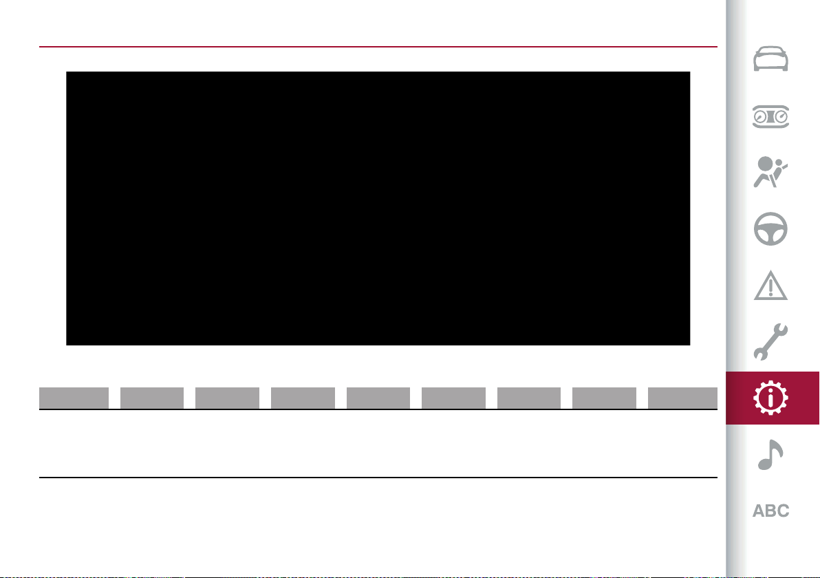
231
DIMENSIONS
Dimensions are expressed in inches/mm and refer to the car equipped with its original tyres. Height is measured with car unladen.
231 10106V0001EM
A B C D E F G H I
33.9 / 861 110.94 / 2818 39.68 / 1008 184.5 / 4687
65.78 / 1671
(*)
65.6 / 1666
(**)
63.5 / 1613 65.08 / 1653 85.16 / 2163 74.9 / 1903
(*) RWD versions
(**) AWD versions
Small variations with respect to the reported values are possible depending on the dimensions of the rims.

TECHNICAL SPECIFICATIONS
232
QUADRIFOGLIO VERSION
Dimensions are expressed in inches/mm and refer to the car equipped with its original tyres. Height is measured with car unladen.
232 10106V0002EM
A B C D E F G H I
34.1 / 866 110.94 / 2818 40.1 / 1018 185.11 / 4702 66.18 / 1681 1622 65.94 / 1675 85.16 / 2163 76.96 / 1955
LUGGAGE COMPARTMENT VOLUME
Capacity (V.D.A. standards)
Non-folding rear seats (unladen car): 115.5 UK gal (525 litres)
233
WEIGHTS
Weights [lb / kg] 2.9 V6 2.0 T4 MAir
200 HP 280 HP
Unladen weight (with all fluids, fuel tank filled to 90% and
without optional equipment)
4033 / 1830 3660 / 1660 3660 / 1660
Payload including the driver (*) 1388 / 630 1411 / 640 1411 / 640
Maximum permitted loads (**)
– front axle 2578 / 1170 2359 / 1070 2359 / 1070
– rear axle 2953 / 1340 2910 / 1320 2910 / 1320
– total 5421 / 2460 5170 / 2350 5170 / 2350
Maximum combined load (permitted maximum load + towable
weight trailer with brakes) (***)
– 8595 / 3900 10138 / 4600
Towable loads
– braked trailer – 3527 / 1600
3527 / 1600
5070 / 2300 (****)
– trailer without brakes – 1653 / 750 1653 / 750
Maximum load on roof – 165 / 75 165 / 75

TECHNICAL SPECIFICATIONS
234
Weights [lb / kg] 2.9 V6 2.0 T4 MAir
Maximum load on tow hitch (trailer with brakes) – 141 / 64
141 / 64
209 / 95 (****)
(*) If special equipment is fitted (trailer towing device, etc.) the unladen car weight increases, thus reducing the specified payload in relation to the
maximum permissible loads.
(**) Loads not to be exceeded. The user is responsible for arranging goods in the luggage compartment and/or on the load platform within the
maximum permitted loads.
(***) Never exceed the maximum combined vehicle load value: the maximum towable load is only allowed if it does not exceed the maximum combined
vehicle load.
(****) If the optional “tow hook” was factory-installed. For the maximum towable load, always refer to the Registration Document.
235
Weights [kg] 2.2 JTD
160 HP/ 190 HP RWD 190 HP / 210 HP AWD
Unladen weight (with all fluids, fuel tank filled to 90% and
without optional equipment)
3660 / 1660 3839 / 1745
Payload including the driver (*) 1474 / 670 1463 / 665
Maximum permitted loads (**)
– front axle 2288 / 1040 2398 / 1090
– rear axle 2888 / 1310 2948 / 1340
– total 5126 / 2330 5302 / 2410
Maximum combined load (permitted maximum load + towable
weight trailer with brakes) (***)
8646 / 3930 10362 / 4710
Towable loads
– braked trailer 3527 / 1600 5070 / 2300
– trailer without brakes 1653 / 750 1653 / 750
Maximum load on roof 165 / 75 165 / 75
Maximum load on tow hitch (trailer with brakes) 141 / 64 209 / 95
(*) If special equipment is fitted (trailer towing device, etc.) the unladen car weight increases, thus reducing the specified payload in relation to the
maximum permissible loads.
(**) Loads not to be exceeded. The user is responsible for arranging goods in the luggage compartment and/or on the load platform within the
maximum permitted loads.
(***) Never exceed the maximum combined vehicle load value: the maximum towable load is only allowed if it does not exceed the maximum
combined vehicle load.
TECHNICAL SPECIFICATIONS
236
REFUELLING
2.9 V6 2.0 T4 MAir
Prescribed fuels and original
lubricants
Fuel tank [UK gal / litres] 14 / 64 14 / 64
Unleaded petrol
(EN228 specifications)
including a reserve of [UK gal /
litres]
2.1 / 9.6 2.11 / 9.6
Main cooling system (UK gal /
litres)
2.46 / 11.2 1.93 (8.8) (**) / 2.02 (9.25) (**) (***)
50% mixture of distilled water and
PARAFLU UP (****)
Secondary cooling system [UK gal /
litres)]
1.25 / 5.75 0.95 (4.3) / 1.15 (5.25) (**)
Engine oil filter [UK gal / litres] – 0.13 / 0.6
SELENIA QUADRIFOGLIO (2.9 V6
engine) / SELENIA DIGITEK P.E. (2.0
T4 MAir engine)
Engine oil sump [UK gal / litres] – 1.01 / 4.6
Engine sump and filter [UK gal /
litres)]
1.42 / 6.5 –
Hydraulic brake circuit [UK gal /
litres]
0.2 / 0.9 0.2 / 0.9
TUTELA BRAKE FLUID EXTREME
HT
Windscreen washer tank [UK gal /
litres]
0.92 / 4.2 0.9 / 4.1 PETRONAS DURANCE SC 35
Automatic transmission AWD [UK
gal / litres]
2.01 / 9.11 2.05 / 9.3
TUTELA TRANSMISSION AS 8
Automatic transmission RWD [UK
gal / litres]
– 2.07 / 9.4
ZF S6-53 manual transmission [UK
gal / litres)]
0.4 / 1.8 –
TUTELA TRANSMISSION
GEARSYNTH (2.9 V6 RWD engine)
237
2.9 V6 2.0 T4 MAir
Prescribed fuels and original
lubricants
Differentials and reduction gears
RDU 230-TV [UK gal / litres]
Main body: 0.18 / 0.8
Left TV: 0.14 / 0.68
Right TV: 0.13 / 0.61
–
TUTELA TRANSMISSION AXLE-
DRIVE (2.9 V6 RWD engine)
RDU 230-LSD differential [UK gal /
litres]
– 0.2 / 0.9
TUTELA TRANSMISSION LS AXLE
FLUID (2.0 T4 MAir engine)
RDU 210-eLSD differential (where
available) [UK gal / litres]
– 0.24 / 1.1
AWD System FAD transfer case
[UK gal / litres]
0.09 / 0.45 0.11 / 0.5
AWD System TRANSFER CASE [UK
gal / litres]
0.15 / 0.7 0.15 / 0.7
TUTELA TRANSMISSION
TRANSFER CASE (2.0 T4 MAir
engine)
(*) 200 HP Versions and 280 HP Versions (without factory-installed "tow hook” optional)
(**) 280 HP versions
(***) If the optional “tow hook” was factory-installed.
(****) When the vehicle is used in particularly harsh weather conditions, we recommend using a 60% mixture of PARAFLU UP and 40% demineralised
water.
TECHNICAL SPECIFICATIONS
238
93) 94)
2.2 JTD Prescribed fuels and original lubricants
Fuel tank [UK gal / litres] 12.7 (58) / 14 (64) (*)
Automotive diesel fuel (EN590 and EN16734
specifications)
including a reserve of [UK gal / litres] 1.98 (9.0) / 2.2 (10) (**)
AdBlue
®
tank (where provided) capacity
approximately [UK gal (litres)]
3.5 / 16.1
AdBlue
®
(DIN 70 070 and ISO 22241-1
specifications)
Main cooling system (UK gal / litres) 1.71 (7.8) / 1.75 (8.0) (***)
50% mixture of distilled water and PARAFLU
UP (*)
Secondary cooling system [UK gal / litres)] 1.03 / 4.7 (***)
Engine oil filter [UK gal / litres] 0.11 / 0.5
Versions with AdBlue
®
: SELENIA W.R.
FORWARD 0W-20
Versions without AdBlue
®
: SELENIA W.R.
FORWARD 0W-20 (150 HP/180 HP engines)
/ SELENIA W.R. FORWARD 0W-30 (210 HP
engines)
Engine oil sump [UK gal / litres] 0.85 / 3.9
Hydraulic brake circuit [UK gal / litres] 0.02 / 0.9 TUTELA BRAKE FLUID EXTREME HT
Windscreen washer tank [UK gal / litres] 0.92 / 4.2 PETRONAS DURANCE SC 35
Automatic transmission [UK gal / litres] 2.0 / 9.1 TUTELA TRANSMISSION AS8
RDU 230-LSD differential [UK gal / litres] 0.02 / 0.9
TUTELA TRANSMISSION LS AXLE FLUID
RDU 210/215-LSD differential [UK gal / litres] 0.24 / 1.1
AWD System FAD transfer case [UK gal / litres] 0.11 / 0.5 TUTELA TRANSMISSION HYPOIDE GEAR OIL
239
2.2 JTD Prescribed fuels and original lubricants
AWD System TRANSFER CASE [UK gal / litres] 0.15 / 0.7 TUTELA TRANSMISSION TRANSFER CASE
(*) For markets where provided.
(**) Versions with 64 litre fuel tank.
(***) 190 HP / 210 HP AWD versions
(****) When the vehicle is used in particularly harsh weather conditions, we recommend using a 60% mixture of PARAFLU UP and 40% demineralised
water.
IMPORTANT
93) Only use AdBlue
®
(UREA) compliant with DIN 70 070 and ISO 22241-1. Other fluids may cause damage to the system: also exhaust emissions
would no longer comply with the law.
94) The distribution companies are responsible for the compliance of their product. Observe the precautions of storage and servicing, in order to
preserve the initial qualities. The manufacturer will not recognise any guarantee in case of malfunctions and damage caused to the car due to the
use of AdBlue
®
(UREA) not in accordance with regulations.
TECHNICAL SPECIFICATIONS
240
FLUIDS AND LUBRICANTS
Your vehicle is equipped with an engine oil that has been thoroughly developed and tested in order to meet the requirements of the
Scheduled Servicing Plan. Constant use of the prescribed lubricants guarantees the fuel consumption and emission specifications.
Lubricant quality is crucial for engine operation and duration.
95)
PRODUCT SPECIFICATIONS
ENGINE LUBRICATION
Use Features Specification
Original fluids and
lubricants
Replacement interval
2.9 V6
SAE 5W-40
ACEA C3
9.55535-GH2
SELENIA QUADRIFOGLIO
Contractual Technical
Reference N°F022.B18
According to Service
Schedule
2.0 T4 MAir
SAE 0W-30
ACEA C2
9.55535–GS1
SELENIA DIGITEK P.E.
Contractual Technical
Reference N°F020.B12
According to Service
Schedule
2.2 JTD
SAE 0W-20
ACEA C2
9.55535–DSX
SELENIAW.R.FORWARD
0W-20
Contractual Technical
Reference N°F013.K15
According to Service
Schedule
2.2 JTD 210 HP (*)
SAE 0W-30
ACEA C2
9.55535–DS1
SELENIAW.R.FORWARD
0W-30
Contractual Technical
Reference N°842.F13
According to Service
Schedule
(*) Versions without AdBlue
®
(UREA).
If lubricants conforming to the specific request are not available, products that meet the indicated specifications can be used to top
up; in this case optimal performance of the engine is not guaranteed.

241
Use Features Specification
Original fluids and
lubricants
Applications
Lubricants and greases for
drive transmission
ATF Synthetic lubricant 9.55550-AV5
TUTELA TRANSMISSION
AS 8
Contractual Technical
Reference N°F139.I11
Automatic transmission
SAE 75W-85 synthetic
lubricant
9.55550-DA9
TUTELA TRANSMISSION
LS AXLE FLUID
Contractual Technical
Reference N°F059.N15
Differential RDU 230-LSD
and RDU 210/215 -LSD
SAE 75W-85 API GL-5
synthetic lubricant
9.55550-DA8
TUTELA TRANSMISSION
AXLE-DRIVE
Contractual Technical
Reference N°F058.N15
Differentials and reduction
gears RDU 230-TV (2.9 V6
engine)
SAE 75W-80 APL GL-5
synthetic lubricant
9.55550-DA10
TUTELA TRANSMISSION
HYPOIDE GEAR OIL
Contractual Technical
Reference n° F060.N15
AWD System FAD Transfer
case
SAE75W synthetic
lubricant
9.55550-DA11
TUTELA TRANSMISSION
TRANSFER CASE
Contractual Technical
Reference N°F061.N15
AWD System TRANSFER
CASE
Lubricants and greases for
drive transmission
NLGI 0-1 grease for
constant velocity joints
with low friction
coefficient
9.55580-GRAS II
TUTELA STAR 700
Contractual Technical
Reference N°F701.C07
Differential side constant
velocity joints

TECHNICAL SPECIFICATIONS
242
Use Features Specification
Original fluids and
lubricants
Applications
Lubricants and greases for
drive transmission
NLGI 1-2 molybdenum
disulphide grease for high
temperatures
9.55580-GRAS II
TUTELA ALL STAR
Contractual Technical
Reference N°F702.G07
Wheel side constant
velocity joints
Brake fluid DOT 4 9.55597
TUTELA BRAKE FLUID
EXTREME HT
Contractual Technical
Reference N°F001.N15
Hydraulic brakes and clutch
controls
Protective agent for
radiators
Protective with antifreeze,
ethylene glycol based
organic formula, free from
amine and 2–EH (2–ethyl
hexanoic acid), containing
corrosion inhibitors and
anti-foam additives. CUNA
NC 956-16, ASTM D 3306
9.55523 or MS.90032
PARAFLU UP
Contractual Technical
Reference N°F101.M01
Use rate 50% Not mixable
with different formulation
products (*)
Windscreen washer fluid CUNA NC 956-11 9.55522
PETRONAS DURANCE SC
35
Contractual Technical
Reference N° F001.D16
To be used diluted or
undiluted in windscreen
washer/wiper systems
AdBlue
®
additive for diesel
emissions
Water-AdBlue
®
solution
DIN 70 070 and ISO 22241-1
AdBlue
®
To be used for filling the
AdBlue
®
tank on versions
equipped with Selective
Catalytic Reduction (SCR)
system (2.2 JTD engine)
Diesel fuel additive
Antifreeze additive for
diesel fuel, with protective
action for diesel engines
PETRONAS DURANCE
DIESEL ART
Contractual Technical
Reference N°F601.C06
To be mixed with diesel fuel
(25 cc per 10 litres)
243
Use Features Specification
Original fluids and
lubricants
Applications
Automatic climate control
system (HVAC)
R1234yf or R134a
(depending on market)
(*) For particularly harsh climate conditions, a mixture of 60% PARAFLU UP and 40% demineralised water is recommended.
IMPORTANT
95) The use of products with specifications other than those indicated above could cause damage to the engine not covered by the warranty.
TECHNICAL SPECIFICATIONS
244
PERFORMANCE
Top performance after the initial period of vehicle usage.
Versions Maximum speed (mph / km/h)
Acceleration from 0-60 mph / (0-100 km/h)
(sec.)
2.9 V6 175 / 283 3.8
2.0 T4 MAir 200 HP AWD 134 / 215 7.2
2.0 T4 MAir 280 HP AWD 143 / 230 5.7
2.2 JTD 150 HP RWD (*) 123 / 198 8.8
2.2 JTD 160 HP RWD 123 / 198 8.8
2.2 JTD 180 HP RWD (*) 130 / 210 7.6
2.2 JTD 190 HP RWD 130 / 210 7.6
2.2 JTD 180 HP AWD (*) 130 / 210 7.6
2.2 JTD 190 HP AWD 130 / 210 7.6
2.2 JTD 210 HP AWD 134 / 215 6.6
(*) For versions/markets where provided
245
FUEL CONSUMPTION AND CO2 EMISSIONS
The fuel consumption and CO
2
emission figures declared by the manufacturer are determined on the basis of the type-approval tests
laid down by the applicable standards in the country where the vehicle is registered.
The type of route, traffic conditions, weather conditions, driving style, general condition of the car, trim level/equipment/accessories,
use of the climate control system, car load, presence of roof racks and other situations that adversely affect the aerodynamics or
wind resistance lead to different fuel consumption values than those measured.
The fuel consumption will get more regular only after having driven the first 1860 miles (300 km).
To find the specific fuel consumption and CO
2
emission figures for this car, please refer to the data in the Certificate of Conformity,
and the related documentation that accompanies the vehicle.

TECHNICAL SPECIFICATIONS
246
PRESCRIPTIONS FOR HANDLING THE CAR AT THE END OF ITS LIFE
(where provided)
For years, Alfa Romeo S.p.A. has pursued a global commitment to protect and respect the environment by continually improving its
production processes and developing increasingly "eco-compatible" products. To grant customers the best possible service in terms
of respecting environmental laws and in response to European Directive 2000/53/EC governing vehicles at the end of their life, Alfa
Romeo S.p.A. is offering its customers the chance to hand over their car at the end of its life without incurring any additional costs.
The European Directive sets out that when the vehicle is handed over the last keeper or owner should not incur any expenses as a
result of it having a zero or negative market value.
To hand your car over at the end of its life without extra cost, contact one of our dealerships if you are purchasing another car or an
Alfa Romeo S.p.A.-authorised collection and scrapping centre. These centres have been carefully chosen to offer high quality service
for the collection, treatment and recycling of vehicles at their end of life, respecting the surrounding environment.
You can find further information on these collection and scrapping centres either from an Alfa Romeo S.p.A. dealership or by calling
the number in the Warranty Booklet or by consulting the Alfa Romeo S.p.A. website.

This chapter describes the main functions of the Connect
system that can be fitted on the vehicle.
MULTIMEDIA
ROADSAFETY .......................................................... 248
RECEPTIONCONDITIONS ............................................. 248
CAREANDMAINTENANCE ............................................ 248
ANTITHEFTPROTECTION ............................................. 248
IMPORTANTNOTES.................................................... 249
CONTROLS ..............................................................250
CONTROLSONTHESTEERINGWHEEL ..............................253
"TOUCHSCREEN"FUNCTION ..........................................256
WIDGET ...................................................................257
RADIO(TUNER)MODE ................................................. 260
MEDIAMODE............................................................ 260
Bluetooth SOURCE ....................................................261
®
USB/iPod/AUXSUPPORT ..............................................261
CLIMATECONTROLSYSTEM..........................................262
PHONEMODE ............................................................263
NAVIGATIONMODE ................................................... 264
SETTINGS................................................................ 266
PERFORMANCE......................................................... 268
VEHICLEINFORMATION............................................... 268
DRIVERASSISTANCE .................................................. 269
AppleCarPlayandAndroidAuto ...................................... 270
VOICECONTROLS .......................................................272
CONNECTEDSERVICES-ALFA CONNECTSERVICES .............274
WIRELESS CHARGING SYSTEM– WCPM (Wireless Charge Pad
Module)....................................................................276
OFFICIALTYPEAPPROVALS .......................................... 277
MULTIMEDIA
248
ROAD SAFETY
217) 218)
Learn how to use the various system
functions before setting off.
Read the instructions for the system
carefully before setting off.
WARNING Look at the screen only and
when it is necessary and safe. If you need
to look at the screen for a long time,
pull over to a safe place so as not to be
distracted while driving. Immediately
stop using the system in the event of
a fault. Otherwise the system might
be damaged. Contact an Alfa Romeo
Dealership as soon as possible to have
the system repaired.
WARNING
217) Follow the safety rules here below:
otherwise serious injuries may occur to the
occupants or the system may be damaged.
218) If the volume is too loud this can be
dangerous. Adjust the volume so that you
can still hear background noises (e.g. horns,
ambulances, police vehicles, etc.).
RECEPTION CONDITIONS
(where provided)
Reception conditions change constantly
while driving. Reception may be
interfered with by the presence of
mountains, buildings or bridges,
especially when you are far away from
the broadcaster.
WARNING The volume may be adjusted
when receiving traffic information and
news.
CARE AND MAINTENANCE
96) 97)
Observe the following precautions to
ensure the system is fully operational:
avoid hitting the display lens with
pointed or hard objects that could
damage its surface;
clean with a damp cloth (microfibre
if possible). If necessary, you can use a
delicate mild soap and water solution,
then dry with a soft, dry cloth. Do not
apply pressure to the display lens while
cleaning;
do not use alcohol, benzines and their
derivatives, ammonia, solvents or other
surfactants to clean the display lens;
prevent any liquid from entering the
system: this could damage it beyond
repair.
IMPORTANT
96) Only clean the front panel and the
display with a soft, clean, dry, anti-static
cloth. Cleaning and polishing products may
damage the surface. Do not use alcohol or
similar products to clean the control panel
or the display.
97) Do not use the display as a base for
supports with suction pads or adhesives
for external navigators or smartphones or
similar devices.
ANTITHEFT PROTECTION
The system is equipped with an
anti-theft protection system based on
the exchange of information with the
electronic control unit (Body Computer)
on the vehicle.
This guarantees maximum security
and prevents the system from being
used on other cars in the event of theft.
If necessary contact an Alfa Romeo
Dealership.

249
IMPORTANT NOTES
Look at the screen only and when it is
necessary and safe. If you need to look
at the screen for a long time, pull over to
a safe place so as not to be distracted
while driving.
Immediately stop using the system in the
event of a fault.
Otherwise the system might be
damaged. Contact an Alfa Romeo
Dealership as soon as possible to have
the system repaired.
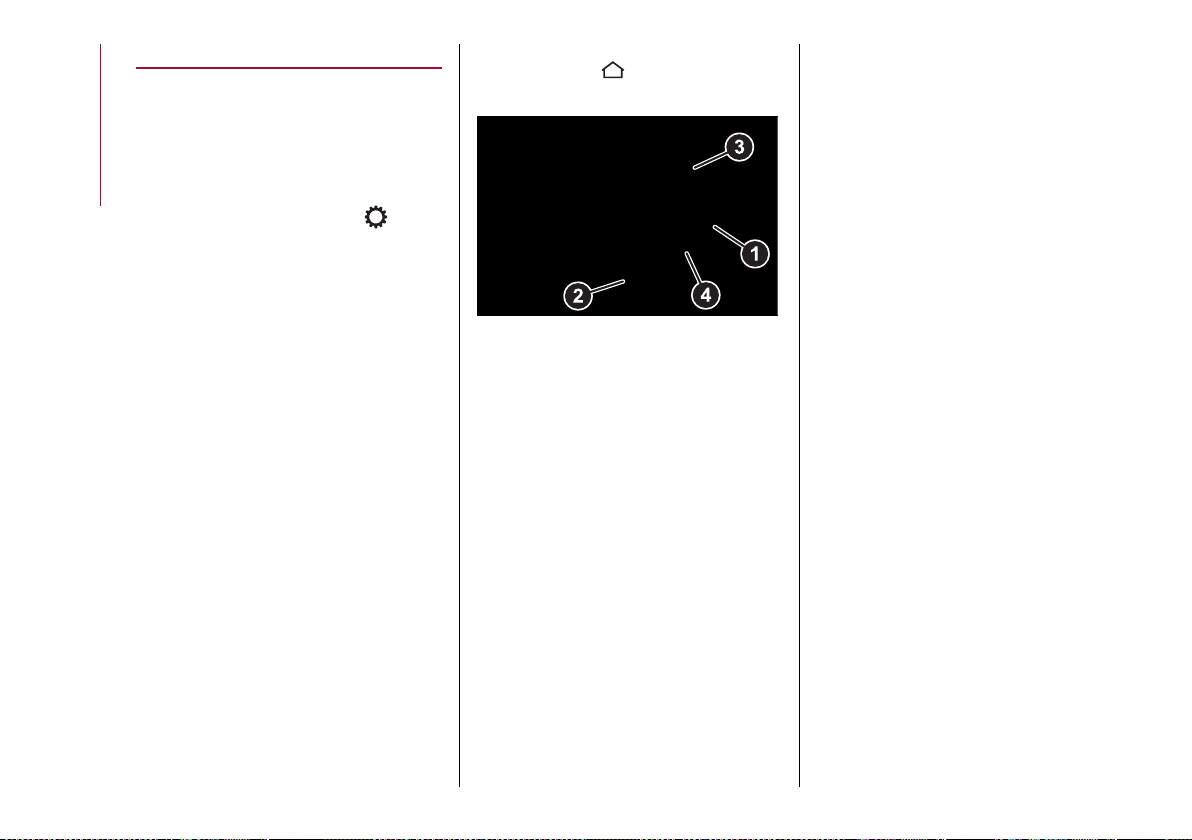
MULTIMEDIA
250
CONTROLS
CONTROLS ON TUNNEL
Onthe central tunnel, fig.233,there are
commands to interact with the Connect
system.
SETTINGS button (1)
Pressing the "Settings" button while
within the modes (”RADIO”, “MEDIA”,
“PHONE”, “NAVIGATION”) will open the
"Settings" Display the mode in question.
Press the button it again will return to
the previously selected mode.
MENU button (2)
Press the button to access the Main
Menu.
233 12126S0300EM
251
DESCRIPTION OF CONTROLS TABLES
ON/OFF and VOLUME control (3)
Action Function
LONG PRESS Switching the Connect system on/off
SHORT PRESS
Radio Mode: Activate/deactivate the Mute function
Media Mode: Activate/deactivate play/pause
Phone Mode: Activate/deactivate the microphone during a phone call
ROTATION Turn clockwise to increase the volume/turn anticlockwise to decrease the volume
MOVE TO THE SIDE
Radio mode: on the right to select next/left radio station/on the left to select previous station
(radio station search can be done by "Frequency"/"Name"/"Favourites")
Media mode: short press on the right: select next track/short press on left select previous track
Long press on right ("Media" mode): go to next track/long press on left, go to previous track
MULTIMEDIA
252
Rotary Pad (4)
Action Function
ROTATION
In the Menus: confirms selection
In Navigation mode (where provided): zooms the maps
SHORT PRESS In the Menus: confirms selection
LONG PRESS Radio mode: store radio station on the radio station bar/store a favourite on the preset bar
BRIEF TOUCH RIGHTWARDS (*)
In the Menus: goes to the submenu of the selected function
In Navigation mode (where provided), in "Browse Map": moves rightwards on the map
Navigation to move inside the navigation map
BRIEF TOUCH LEFTWARDS (*)
In the Menus: goes back to the previous menu ("Esc" function)
In Navigation mode (where provided), in "Browse Map": moves leftwards on the map Navigation
to move inside the navigation map
BRIEF TOUCH UPWARDS (*)
In the Menus: closes the preset bar
In Navigation mode (where provided), in "Browse Map": moves upwards on the map Navigation
to move inside the navigation map
BRIEF TOUCH DOWNWARDS (*)
Activating radio presettings/Saving "Contacts" and "Destinations"
In the Menus: opens the preset bar
In Navigation mode (where provided), in "Browse Map": moves downwards on the map
Navigation to move inside the navigation map
(*) The Rotary Pad must be tilted in the indicated direction ("tilt" function)
253
CONTROLS ON THE STEERING WHEEL
DESCRIPTION
The controls for the main system functions are present on the steering wheel to make control easier.
The activation of the function selected is controlled, in some cases, by how long the button is pressed (short or long press) as
described in the following tables.
234 11046V0001EM
CONTROLS ON STEERING WHEEL SUMMARY TABLE
Button (1)
Action Function
SHORT PRESS
In Radio mode: select the next radio station.
In Media mode: select the next track.
LONG PRESS
In Radio mode: scan higher frequencies until released.
In Media mode: fast forward track.
MULTIMEDIA
254
Action Function
SHORT PRESS
In Radio mode: select the previous radio station.
In Media mode: select the previous track.
LONG PRESS
In Radio mode: scan lower frequencies until released.
In Media mode: fast rewind track.
Voice control button (3)
Action Function
SHORT PRESS
With voice session not active: activation of Connect system voice
controls.
With voice session active: immediately close voice session in progress.
LONG PRESS
With voice session active: interrupt voice session in progress (a new
voice control can be imparted).
With voice session not active and external audio device connected
(e.g. Apple CarPlay / Android Auto/Car Life): activate voice session of
connected device.
NOTE If Apple CarPlay and Android Auto apps are present, Siri voice assistant (for Apple CarPlay) or Google Assistant (for Android Auto) will be
activated. In this case you can use "Natural language" voice controls and not just the specific ones preset for the Connect system.
Phone button (4)
Answers/ends call or shows Recent Calls list.
Button (2)
255
SHORT PRESS
In Radio mode: activate/deactivate the Mute function.
In Media mode: activate play/pause.
In Phone mode: activate/deactivate the microphone Mute function.
Volume Control (5)
Action Function
ROTATION
Upwards: turn the volume up
Downwards: turn the volume down
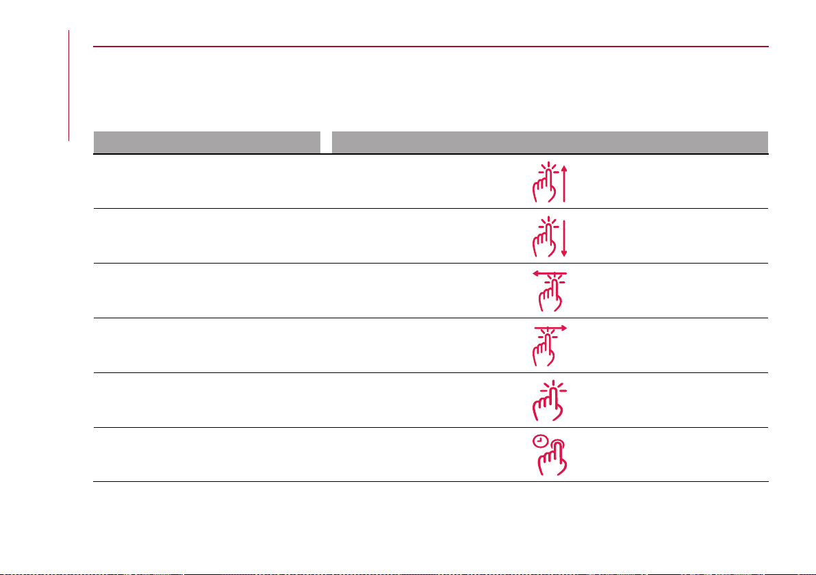
MULTIMEDIA
256
"TOUCHSCREEN" FUNCTION
The Connect system is also equipped with a touchscreen function: in addition to the selection of items using the controls on the
central tunnel and on the steering wheel, it is possible to interact with the various functions/modes by pressing on the icons shown
the display.
ACTIONS THAT CAN BE PERFORMED USING THE TOUCHSCREEN FUNCTION
Function Action on the display
SCROLL UP
SCROLL DOWN
MOVE LEFTWARDS
MOVE RIGHTWARDS
SHORT PRESS
LONG PRESS
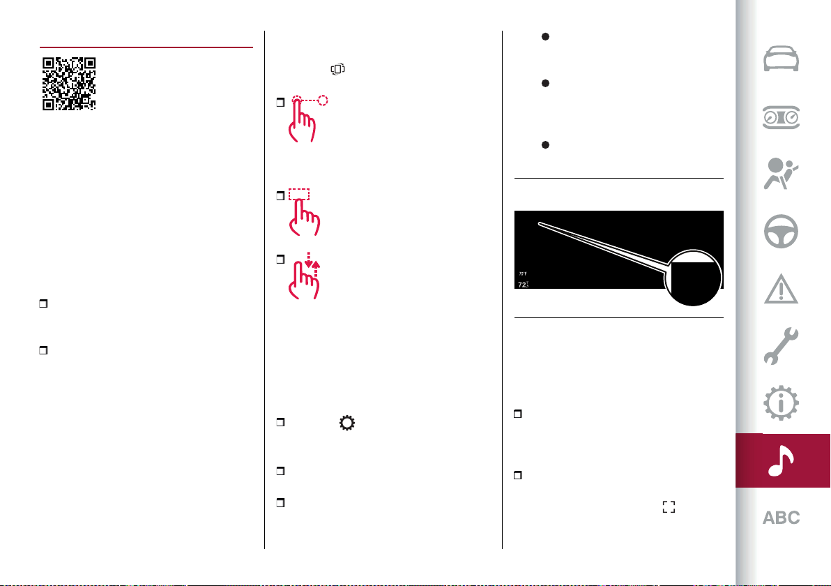
257
WIDGET
WIDGET INTERACTION MODES
The Connect system display shows
widgets which can be used to access the
various operating modes of the system
itself.
You can interact with the widgets on
the Main Menu using the touchscreen
function or using the Rotary Pad located
on the central tunnel.
One of the following operations can be
performed:
open the widget by pressing on it
(touchscreen) or by pressing the Rotary
Pad;
scroll the widgets
rightwards/leftwards using the
touchscreen function or by turning the
Rotary Pad rightwards/leftwards.
MOVING THE WIDGETS
You can move the widgets on the display
using the touchscreen function or using
the commands located on the central
tunnel.
Using the touchscreen function
Select the desired widget or press the
"Reorder" button on the vertical
status bar and then:
Moving the widget: hold
the desired widget pressed for a few
seconds and then move it to the right or
left of the display.
Resizing the widget: press the
widget resize icon to be resized.
View widget content: select the
desired widget and then scroll vertically.
When reordering the widgets (viewing
their thumbnails), it will not be possible
to view their contents.
Using the controls located on the
central tunnel
Proceed as follows:
press the button on the central
tunnel:a horizontalbar graph fig.235 will
appear on the upper part of the display;
turn the Rotary Pad to select the
"Settings" item;
press the Rotary Pad to confirm the
selection and then select one of the
following items:
"Widget reorder": to move the
desired widget to the right or left of
the display.
"Widget resize": to change the
size of the widget display to "1/3
view" or "2/3 view" of the display
area.
"Widget content": to view the
content of the desired widget.
RESIZING WIDGETS
Some widgets can occupy 1/3 or 2/3 of
the display area.
Using the touchscreen function
"1/3" viewfig.236: icons, menuname,
main information, graphic buttons (up
to3)(where provided) appearonthe
display.
"2/3"viewfig.237: toactivatethe
enlarged display of the widget, press
the "enlarge" graphic button (where
present) located on the top of the widget
235 12126S0906EM
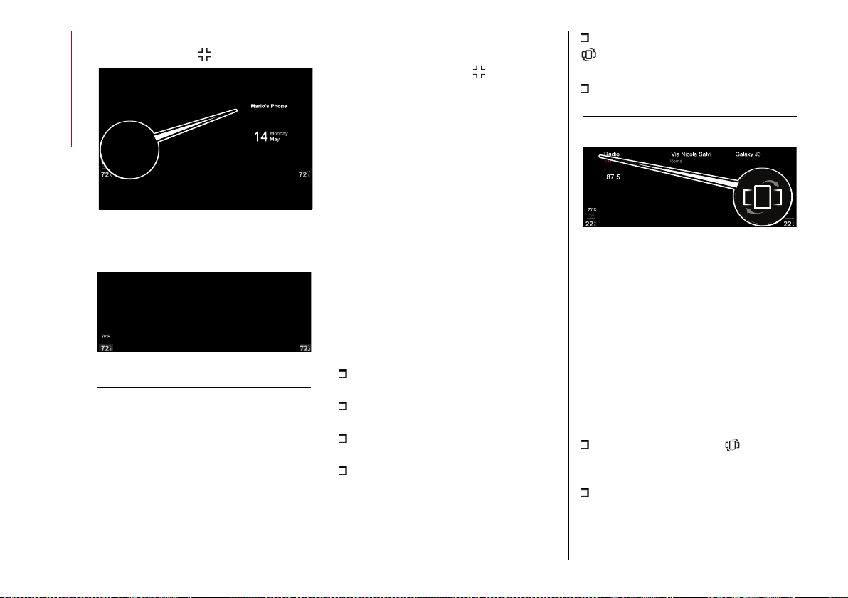
MULTIMEDIA
258
itself. To return from the "1/3" view, press
the graphic button
236 12126S0909EM
Using the controls located on the
central tunnel
Activate the "Settings" menu and then
select the item "Widget resize".
Only the resizeable widgets will be
activated (these will appear on the
display with a different colour from
those that cannot be resized and
therefore cannot be selected).
To resize the widget and switch to "2/3"
view, press the Rotary Pad.
Press the graphic button to return to
the normal view.
NOTE It is not possible to keep two
widgets in "2/3 view" mode on the display
at the same time.
VIEWING WIDGET CONTENTS
Using the touchscreen function
To change the widget view, select it
and swipe vertically, either upwards or
downwards.
Using the controls located on the
central tunnel
Activate the "Settings" menu and then
select the "Widget content" item: only
the widgets with content will be active
and selectable on the display.
Proceed as follows to view the contents
of the widgets:
turn the Rotary Pad to select the
desired widget;
press the Rotary Pad to confirm the
selection;
turn the Rotary Pad to display the
contents of the widget;
press the Rotary Pad to keep the
display active and exit the widget.
REORDER THE WIDGETS
The widgets can be reordered on the
Main Menu in two different ways:
"Explicit": by pressing the "Reorder"
graphic button located on the upper
leftofthe displayfig. 238
"Implicit": by holding the desired
widget pressed for a few seconds.
238 12126S0919EM
Using the touchscreen function
Explicit mode
In both modes, the size of the widgets
will be reduced and displayed, up to a
maximum of 5, on the display.
NOTE When reordering the widgets
(viewing their thumbnails), it will not be
possible to view their contents.
Proceed as follows:
press the graphic button located
in the upper left part of the display: the
first widget will be displayed;
press and hold down the desired
widget and drag it to the desired
position;
Phone
237 12126S0910EM
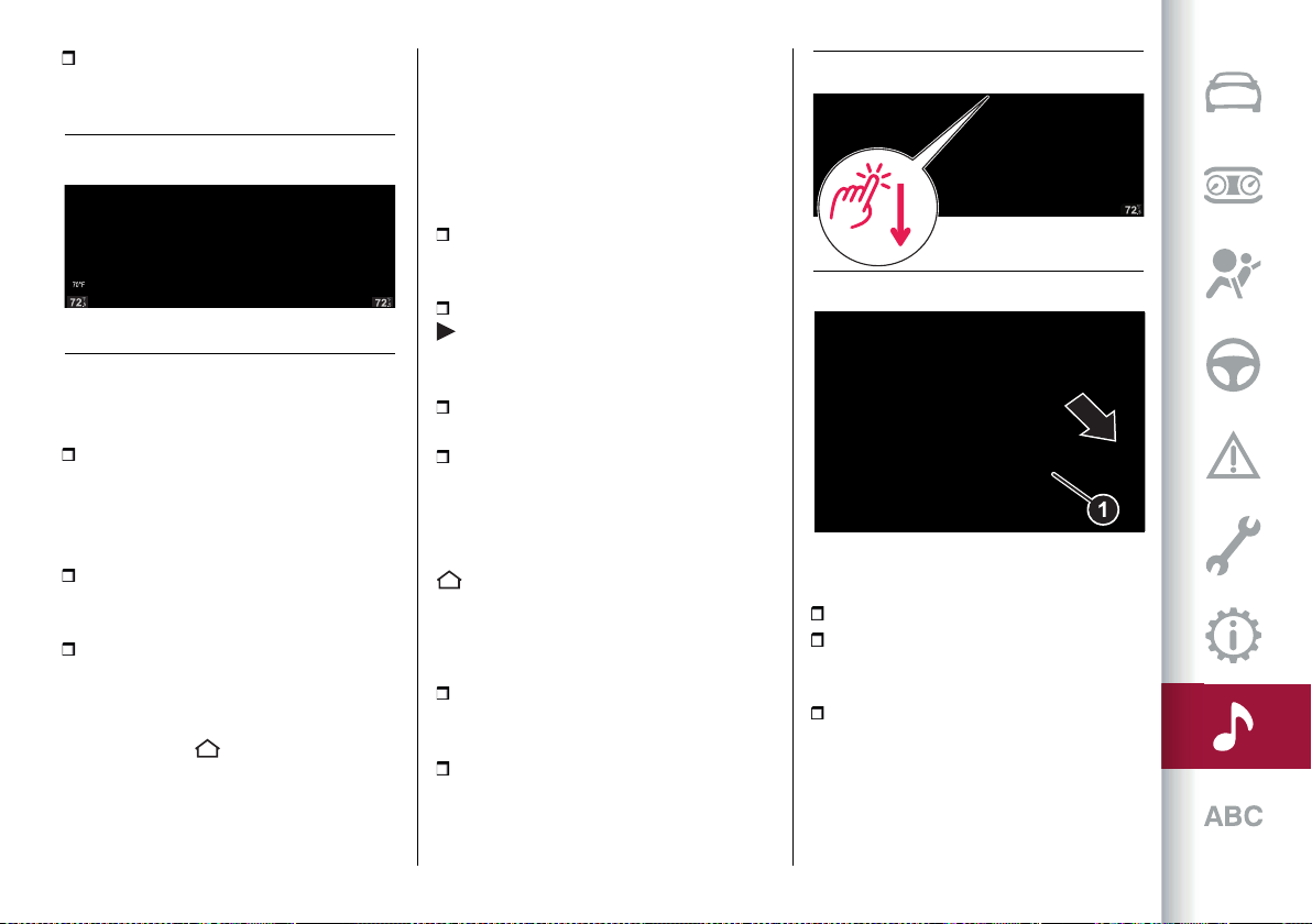
259
release the widget: the new position of
the widget will be stored by the Connect
system.
Implicit mode
Proceed as follows:
hold the desired widget pressed: the
widgets will be reduced and displayed,
up to a maximum of 5, on the display. The
selected widget will remain displayed
and will be larger in size;
press and hold down the desired
widget and drag it to the desired
position;
release the widget: the new position of
the widget will be stored by the Connect
system.
To return to the Main Menu press the
graphic buttons or <
Using the controls located on the
central tunnel
Activate the "Settings" menu and then
select "Widget reorder": the first widget
will be displayed automatically.
Proceed as follows to reorder the
widgets:
turn the Rotary Pad and select
the desired widget: the widget will be
highlighted on the display;
press the Rotary Pad: a graphic arrow
will appear next to the widget,
indicating the direction in which you can
move the widget;
turn the Rotary Pad to move the
widget to the desired position;
press the Rotary Pad to store the new
widget location (the widget will continue
to be highlighted on the display).
To go back to the Main Menu, turn the
Rotary Pad to the left or press the button
on the central tunnel.
SHORTCUT MENU
Proceed as follows to activate the status
bar display:
Using the touchscreen function: touch
the upper partofthedisplay, fig.240,and
slide your finger down.
Using the controls on the central
tunnel: move Rotary Pad 1 fig.241
downwards.
241 12126S0765EM
The "shortcut" menu can be used to:
access the "Settings" menu;
quickly access the stored radio station
"Favourites" or "Contacts" or navigation
"Destinations";
add graphic buttons to quickly access
the desired function.
Phone
239 12126S0922EM
72.5
°F
70°F
ext.
Climate Settings
mi
days
Vehicle Information
240 12126S0953EM
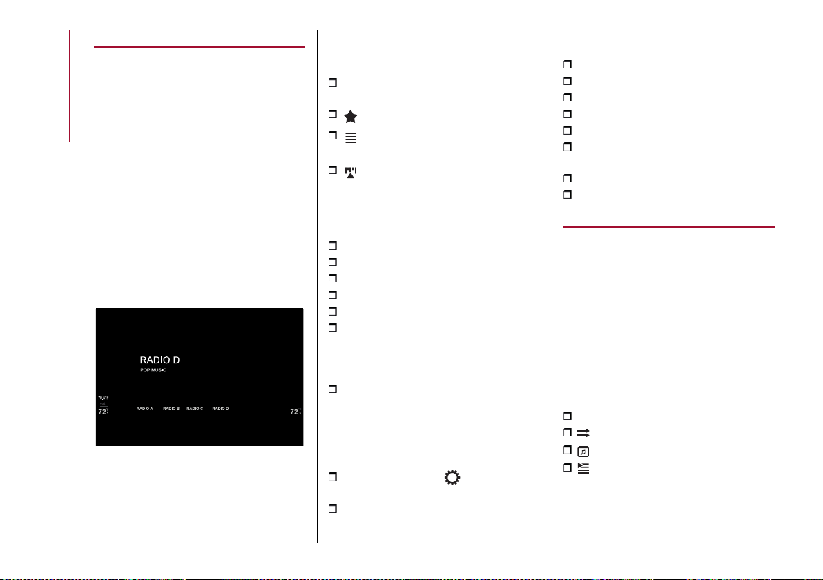
MULTIMEDIA
260
RADIO (TUNER) MODE
RADIO MODE SELECTION (TUNER)
"RADIO" mode can be activated by using
the appropriate widget in the main menu
of the Connect system.
NOTE Some "RADIO" mode functions
can be activated in addition to using the
Rotary Pad and/or the touchscreen
function, also using voice controls: for
more information, see the "AM/FM/DAB
Radio voice commands" paragraph in
the "Voice controls" section in this
publication.
MAIN SCREEN RADIO MODE
The following information will be
displayed after selecting the desired
radio station onthe display fig. 242.
242 12126S0930EM
Sidebar fig. 242
The following graphic buttons are
displayed on the sidebar:
SRC: can be used to select the required
frequency band;
to select the Favourites list;
to view the list of available radio
stations;
to manually seek a radio station.
Central zone of the display fig. 242
The following information is displayed in
the central area of the display:
selected frequency band (e.g. FM);
name of the current radio station;
logo of the active frequency band;
transmitted programme type;
current radio station frequency;
radio mode graphic buttons
(select previous radio station,
activate/deactivate mute function,
select next radio station);
list and name of stored radio stations.
AUDIO
(where provided)
Proceed as follows to open the "Audio"
menu:
press the “Settings” button on the
central tunnel;
turn the Rotary Pad to select the
"Audio Settings" item.
When the function is activated, the
following parameters can be set:
"Bass" (-9; 0; +9);
"Treble" (-9; 0; +9);
"Mid" (-9; 0; +9);
“Balance/Fade”;
"Volume Speed" (OFF; +5);
“Surround Sound” (OFF/ON) (where
provided);
"AUX Volume Comp." (OFF; +20);
"Restore settings".
MEDIA MODE
NOTE Some "MEDIA" mode functions
can be activated in addition to using the
Rotary Pad and/or the touchscreen
function, also using voice controls:
for more information, see the "Media
voice controls" paragraph in the "Voice
controls" section in this publication.
AUDIO SOURCE SELECTION
When the MEDIA source is active, the
following information is shown on the
display fig. 243:
SRC: activate the list of sources
to activate Shuffle/Playback Mode
to activate Tracks Library
to activate the Playlists
Press the graphic button to activate
"MEDIA" mode SRC: the display shows
the available sources: AM, FM, DAB,
Bluetooth
®
, USB1, USB2.
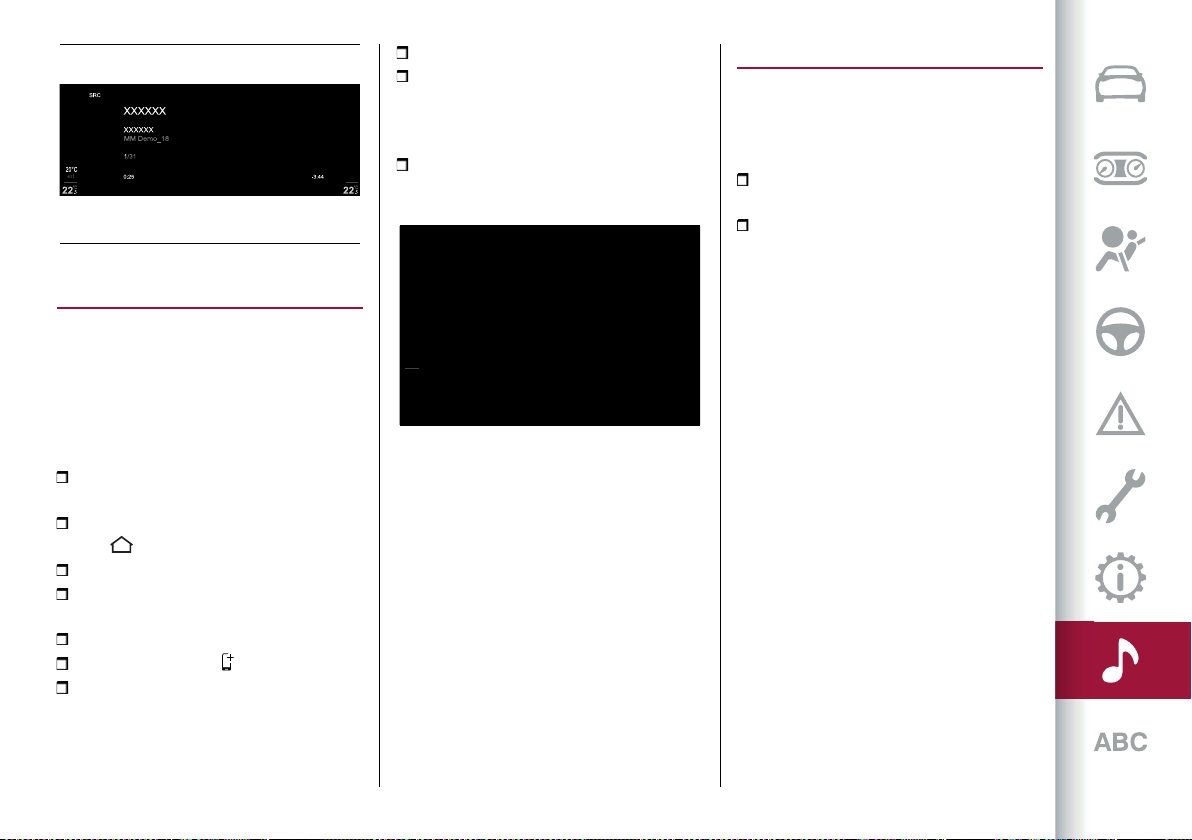
261
243 12126S0937EM
Bluetooth
®
SOURCE
Bluetooth
®
ACTIVATION
This mode is activated by pairing a
Bluetooth
®
device containing music
tracks with the system.
PAIRING A Bluetooth
®
AUDIO DEVICE
Proceed as follows:
activate the Bluetooth
®
function on
the device;
open the main menu by pressing
button and select “Settings”;
select “Infotainment”;
select "Phone" and then "Bluetooth
Settings";
select theBluetooth
®
fig. 244device;
select "Add Device" ;
search for the Connect system on the
Bluetooth
®
audio device (during the
pairing stage a screen will appear on
the display showing the progress of the
operation);
select the device to be paired;
when requested by the audio device,
enter the PIN code shown on the system
display or confirm on the device the PIN
displayed;
if the pairing procedure is completed
successfully, a dedicated screen will
appear.
70°F
ext.
72
.5
°F
72
.5
°F
244 12126S0430EM
The Bluetooth
®
function can also be
reached by pressing the "OPTIONS"
button in the "PHONE" or "MEDIA
functions", which can be selected on the
main menu.
WARNING If the Bluetooth
®
connection
between mobile phone and system is
lost, consult the mobile phone handbook.
USB/iPod/AUX SUPPORT
USB/iPod MODE
To activate the USB/iPod mode insert
the corresponding device (USB or iPod)
in one of the USB ports located:
underneath the automatic dual-zone
climatecontrolpanel, 1 fig.245;
inside the glove compartment
underneaththe frontarmrest, 2 fig. 246.
NOTE The Connect system may not
support some USB keys: in this case,
it may not automatically switch from
“Radio” mode to “Media” mode. If the
device used does not play, verify its
compatibility by selecting “Media” mode:
a dedicated message will appear on the
Connect system display.
WARNING After using a USB recharging
socket, we recommend disconnecting
the device (smartphone), always
removing the cable from the vehicle
socket first, never from the device.
Cables left flying or connected
incorrectly could compromise correct
recharging and/or the USB socket
condition.
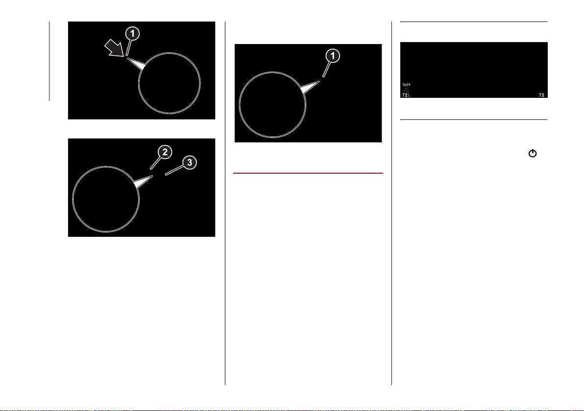
MULTIMEDIA
262
245 04026S0981EM
246 04026S0993EM
USB socket (battery charger)
The glove compartment underneath the
front armrest also contains a third USB
socket 3 fig.246 foruseasa"battery
charger" only.
AUX SOURCE
To activate AUX mode, insert an
appropriate device in the AUX socket 1
fig.247 on the car.
When a device is connected to that
socket, the system starts reproducing
the connected AUX source, if it is already
playing.
247 04026S0982EM
CLIMATE CONTROL SYSTEM
The Connect system lets you interact
with the automatic dual-zone
climate control system to adjust the
temperature inside the passenger
compartment.
NOTE The climate control widget is only
active via the touchscreen function.
The climate control widget in the Main
Menu can display two different contents:
"Air distribution" fig. 248 and"Comfort"
(present only in case of heated electric
seats and heated electric steering
wheel).
Scroll up/down on the widget you can
change the display.
Pressing the widget to activate the "Air
Distribution" or "Comfort" screen.
On the climate control system widget
is displayed a single graphic button
(activated only using the touchscreen
function) which, if pressed, allows you to
turn off the automatic dial-zone climate
control system and then turn it back on
in its last active configuration before
turning off.
"AIR DISTRIBUTION" SCREEN
The "Air Distribution" menu can be used
to adjust the air temperature on driver
and passenger side.
Graphic buttons are present on the
screen for activating the same functions
which can be selected using the buttons
on the display of the automatic dual-zone
climate control system located in the
passenger compartment (see "Climate
control system" paragraph in the
"Knowing your car" chapter).
248 12126S0970EM
.5
°F
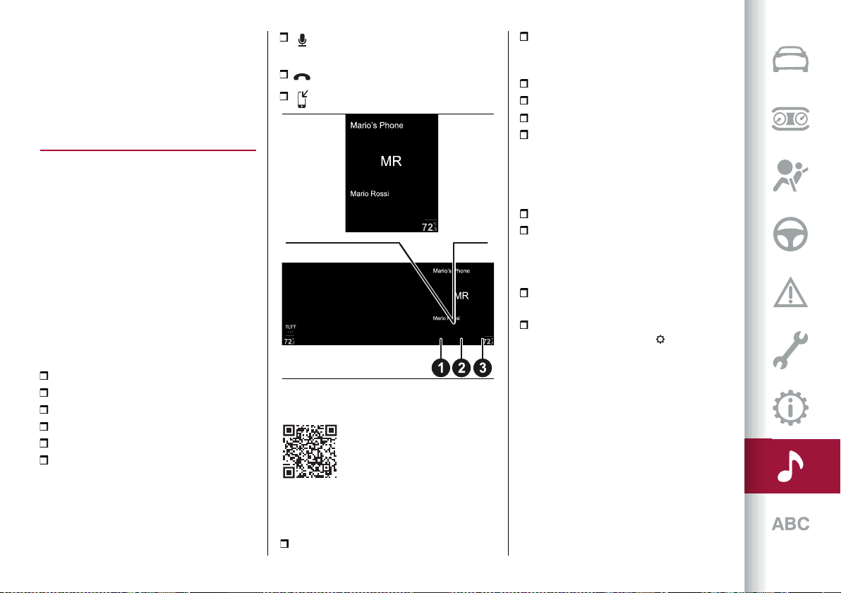
263
"COMFORT" SCREEN
(where provided)
The "Comfort" screen can be used
to adjust the heating level of driver
and passenger seat and of the steering
wheel.
PHONE MODE
NOTE Some "TELEPHONE" mode
functions can be activated in addition
to using the Rotary Pad and/or the
touchscreen function, also using voice
controls: for more information, see
the "Phone voice controls" paragraph
in the "Voice controls" section in this
publication.
INDICATIONS ON THE DISPLAY
The “PHONE” mode widget appears on
the main menu.
The widget display vary according to the
following conditions:
Paired mobile phone
No paired mobile phone
Phone call in progress
Multiple phone call in progress
Outgoing telephone call
Phone conference in progress
Paired mobile phone
If you have already paired your mobile
phone (see the following pages), the
following threegraphic buttons fig. 249
will appear on the "PHONE" widget:
Turn the microphone on/off during
a phone call (1);
End call (2);
Transfer call to device (3).
249 12126V0417EM
PAIRING A MOBILE PHONE
Pairing procedure
To pair the mobile phone, proceed as
follows:
activate the Bluetooth
®
function on
the device;
in the main menu, select the
“SETTINGS” function by turning and
pressing the Rotary Pad;
select “Infotainment”;
select the Bluetooth
®
device;
select "Add device";
search for the Connect system on the
Bluetooth
®
audio device (during the
pairing stage a screen will appear on
the display showing the progress of the
operation);
select the device to be paired;
when requested by the device, enter
the PIN code shown on the system
display or confirm the PIN displayed on
the device;
if the pairing procedure is completed
successfully, a screen is displayed;
the Bluetooth
®
function can also be
activated by pressing the "PHONE"
or "MEDIA" functions, which can be
selected from the main menu.
WARNING Perform the telephone pairing
operation only while the car is stationary
and in safe conditions. Only do this with
the car stationary and in safe conditions.
The feature is disabled when the car is
moving faster than 5 km/h.
WARNING If the Bluetooth
®
connection
between mobile phone and system is lost
consult the mobile phone handbook.
MULTIMEDIA
264
MAKING A PHONE CALL
With the "PHONE" function on, you can
make a call in the following ways:
by selecting "Phone Book" on the
display or "Recent Calls" and then
selecting a contact from the suggested
list;
or
by selecting "Dial" item on the display.
MAIN PHONE MENU
When a mobile phone is connected to
the Connect system, various items (if
available) will appear on the main menu
fig. 250:
network signal intensity;
mobile phone battery charge;
mobile phone name.
250 12126S0421EM
The other information shown on the
display is:
"Dial"(1fig.250): press this graphic
button to show the "dial number" screen
on the display which can be used to dial
the telephone.
"Recentcalls"(2fig.fig.250): press
this graphic button to choose between
"All Calls" and "Missed Calls".
"Favourites" (3 fig. fig. 250):
press this graphic button you can
choose between "Edit favourites", "Add
favourites", "Reorder favourites" and
"Delete favourites".
"SMS" (4fig.fig.250): press this
graphic button to receive and send text
messages (if supported by the device).
The car must be stationary to read the
messages. The listening function and
the sending of default messages which
can be customised by the driver is
always possible. If an unread message is
present, it is indicated by a dot next to
the "SMS" graphic button (a maximum
of 99 unread text messages can be
present).
"Contacts" (5fig. fig. 250): press
this graphic button on the display to
show the list of all contacts registered
on the phone. When you select a contact,
the phone number and the photo (if any)
linked to the contact appear on the right
of the display.
NAVIGATION MODE
(where provided)
LEGAL/ SAFETY NOTICE
When Connect is used for the first time,
after resetting the default settings
and having changed the language,
the system will ask you to accept a
safety/legal notice, warning you about
the responsibilities involved in the
product use while navigating.
NOTE Some "NAVIGATION" mode
functions can be activated in addition
to using the Rotary Pad and/or the
touchscreen function, also using voice
controls: for more information, see
the "Navigation controls" paragraph
in the "Voice controls" section in this
publication.
NAVIGATION ACTIVATION
The “NAVIGATION”mode widgetfig. 251
appears on the main menu.
NOTE The widget is only active using the
touchscreen function.
The graphic button on the widget varies
depending on whether navigation has
been activated or is not activated .
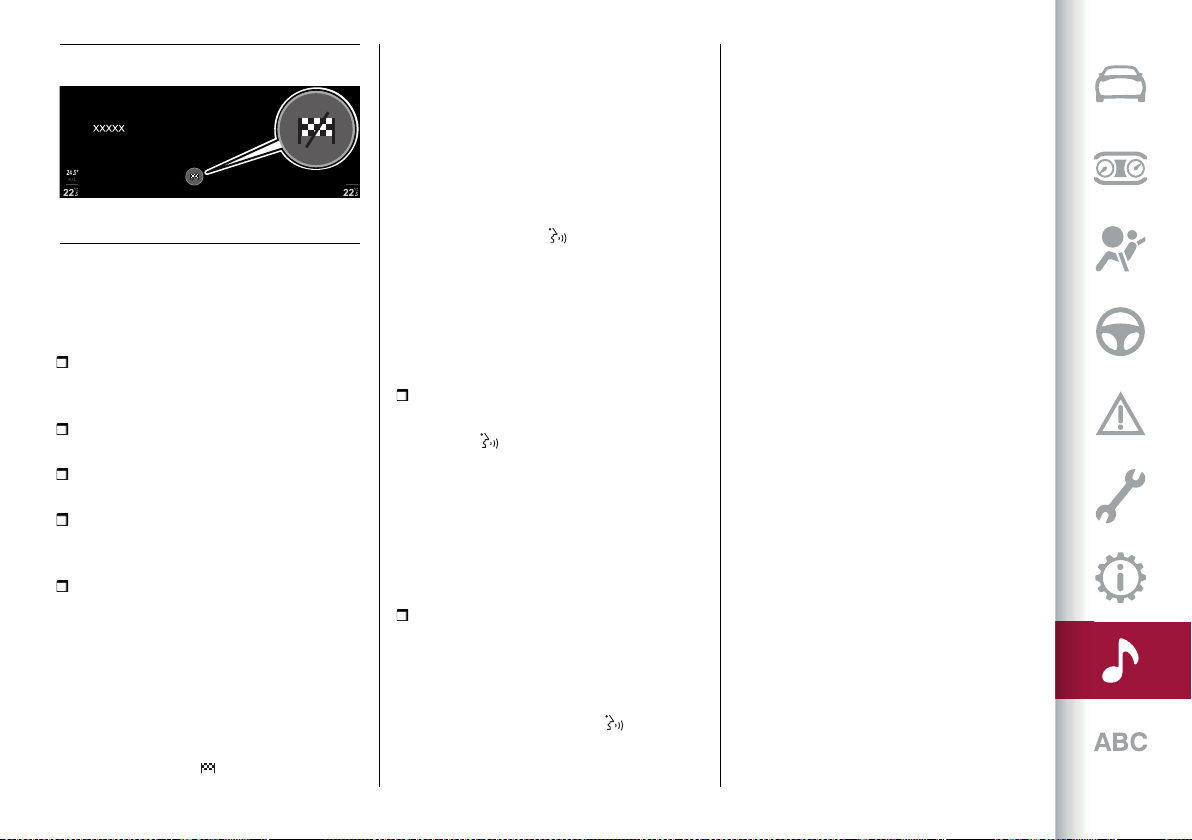
265
251 12126S2010EM
SETTING A DESTINATION
The following data are required to set a
destination:
"City/Post code": enter the name
or ZIP code of the city of the new
destination arrival point;
"Address": enter the street name of
the new destination;
"House Number": enter the house
number of the new destination;
"State" (where applicable/necessary):
enter the name of the state of the new
destination arrival point.
"Start Navigation": select the desired
destination using the right side of the
display. This will provide access to the
route planning screen to start navigating.
NOTE The data above can be order
entered in any order ("Free Text Search"
function).
To set a new destination, select
the graphic button (using the
"touchscreen" function or by rotating
the Rotary Pad): the graphic keyboard
for entering the destination address will
appear on the display and the list of
"Destinations" will appear on the right
side.
Management of voice recognition for
entering navigation addresses
Pressing the button on the right
side of the steering wheel to start the
voice recognition session and send the
necessary commands to the Connect
system to enter a navigation address.
You can enter addresses in two different
ways:
One-shot: Say "Navigate to <City,
Address, House Number>" after pressing
the button on the right side of the
steering wheel and starting the voice
recognition session. The Connect system
will be able to recognise the address
you inserted or display a list of possible
alternatives. Then follow the instructions
provided by the Connect system to start
route calculation.
Manual entry: The Connect system will
help you entry individual fields through a
guided procedure, with the possibility of
using the "City", "Address" and "House
Number" voice commands. To activate
this mode, press the button located
on the right side of the steering wheel
and starting the voice recognition
session, send the first command to
enter the city and continue following the
instructions provided by the Connect
system.
If a language change is made on the
Connect system, using the dedicated
menu in the "Settings" on the display, a
pop-up screen will appear informing the
driver of the limited availability of the
voice recognition functions.
If you choose the English language on a
car sold in Italy the following message
will appear on the display of the Connect
system: "When the vocal system is set
to English you can input addresses
in the United Kingdom, Ireland, Malta
and Gibraltar. You can also insert all
destinations manually.".
WARNING The above message is located
according to the country of destination
of the vehicle. Only the countries shown
on this pop-up screen will be available
with voice recognition functions for
address and destination selection. The
available countries will change according
to the language type selected by the
driver.
NOTE The "one-shot" address entry
mode will not be available if the driver
chooses a language other than the one
used in the country in which the car was
marketed. In this case, in order to access
the voice recognition functions and enter
a valid address, i.e. recognisable by the
MULTIMEDIA
266
Connect system, you will need to send to
the Connect system a voice command to
change country in advance (for each use
of the car). For example, if you choose
English language on a car sold in Italy,
you will need to use the voice command
"Change country" to start the address
entry procedure.
STOPPING NAVIGATION
After starting the navigation, it can be
stopped at any moment.
To deactivate navigation, press the
graphic button
The display will show a dedicated
message. Select “Confirm” to confirm
the choice, or “Cancel” to cancel the
operation.
If “Confirm” is selected, the display will
return to the main navigation screen.
SETTINGS
ACTIVATING THE SETTINGS MENU
The "Settings" menu can be activated by
using the appropriate widget on the main
menufig. 252.
The following items are available in the
menu:
"Lights"
"Units & Language"
"Clock & Date"
"Passive Safety"
"Convenience & Comfort"
“Doors & Locks”
"Cluster"
"Infotainment"
"System"
Lights
The following settings can be modified
when this mode is selected:
"Headlight Sensor"
"Follow Me"
"Cornering Lights"
"Flash Lights with Lock"
"Daytime Running Lights"
"Courtesy Lights"
"Interior Ambient Lighting"
"Restore Settings"
Units & Language
The following settings can be modified
when this mode is selected:
"Units"
"Language"
"Restore settings"
Clock & Date
The following settings can be modified
when this mode is selected:
"Sync with Gps Time"
"Set Time"
“Set Date”
“Time Format”
"Restore Clock and Date Settings"
Passive safety
The following settings can be modified
when this mode is selected:
"Passenger airbag": this is used to
activate/deactivate the front passenger
airbag function.
When the function is accessed:
the system will detect the
activation/deactivation status of the
Climate
Vehicle Information Settings
70°F
ext.
72
.5
°F
72
.5
°F
mi
days
252 12126S2000EM
267
airbags and confirm change of status.
Press the Rotary Pad to continue. The air
bag status is visible through the LEDs
next to the status icon on the dashboard.
Passenger protection activated:
the ON LED switches on with a
steady light.
Passenger protection
deactivated: the OFF LED switches
on with a steady light.
Auto Park Brake" (where provided):
allows you to activate/deactivate the
electric park brake engagement when
the engine is stopped.
"Brake service" (where provided):
this can be used to activate ("Yes") or
deactivate ("No") the procedure to effect
brake system maintenance.
"Seat Belt Reminder": this is used to
enable ("OK") or disable ("Cancel") the
acoustic signal for the SBA (Seat Belt
Alert) system.
"Automatic mirror folding"
(where provided): This function
activates/deactivates automatic folding
of the mirrors when the doors are
locked/unlocked. The default setting is
“Off”.
“Restore Settings”: allows you to
delete the previously settings from this
menu and restore the default settings.
Convenience & Comfort
The following settings can be modified
when this mode is selected:
“Passive Entry" (where provided):
allows you to activate ("On") or
deactivate ("Off") the automatic door
closing
“Restore Settings”: allows you to
delete the previously settings from this
menu and restore the default settings.
Doors & Locks
The following settings can be modified
when this mode is selected:
"Door lock in motion"
"Unlock all doors on exit"
"Door unlock on entry" (where
provided)
"Sound Horn with Remote Start"
(where provided)
"Sound Horn with lock" (where
provided)
"Auto Relock" (where provided)
"Electric tailgate"
"Automatic tailgate opening"
"Convenience & Comfort"
"Restore Settings"
Control panel
The following settings can be modified
when this mode is selected:
"Buzzer volume"
"Trip B"
"Show Phone Info"
"Show Audio Info"
"Show Nav Info"
"Digital speed on all screens"
"Consumption bar"
"Performance pages"
"Custom areas"
"Restore settings"
Infotainment
The following settings can be modified
when this mode is selected:
"Screen Off"
"Display brightness"
"Audio"
"Home Page"
"Bluetooth
®
"
"Device Manager"
"Entertainment"
"Phone"
"Projection mode"
"Navigation"
"Performance Pages"
"Android Auto"
"Connected Services" (where
provided)
"Driver Assistance"
System
The following settings can be modified
when this mode is selected:
"Auto-On Radio"
MULTIMEDIA
268
"Switch-Off Delay"
"Software Update"
"Map Update"
"Restore All Settings"
MAP UPDATE
To ensure optimal performance, the
navigation system must be updated
periodically.
For this, the Mopar
®
Map Care service
offers a new map update every three
months.
The updates can be downloaded from the
maps.mopar.eu website and installed
directly on the Connect system. All
updates are free of charge for 3 years
from the start of the warranty on the car.
The navigation system can also be
updated at the Alfa Romeo Dealership.
NOTE The dealer may charge for
updating the navigation system.
Map update procedure
Proceed as follows to update the
navigation maps:
start the engine;
with the car stationary, insert the USB
key, containing the updated maps, into
one of the USB ports located on the
central tunnel;
select the “Update Map” option from
within the “Map Update” function. The
display will show a screen with the
version and the duration of the whole
procedure in minutes;
select the “Update” function. The
display will show a screen with the
instructions to be followed and a request
for confirmation;
confirm to start the process.
During the update, the instructions to be
followed will continue to be displayed
together with the process progress. You
can move the car during this phase.
PERFORMANCE
The "Performance pages" can be
activated by using the appropriate
widgeton themainmenu fig.253.
The following information is shown on
the main screen of the "Performance
pages":
"Technical gauges"
"Consumption history"
"Efficient Drive"
"Engine torque"
"Temperatures" (Quadrifoglio version
only)
"Drag Race" (Quadrifoglio version only)
"Performance content" (where
provided)
Turn the Rotary Pad to select the desired
item and then press the Rotary Pad to
confirm the selection and access the
menu or, using the touchscreen function,
touch the display to select the desired
item.
VEHICLE INFORMATION
The "Vehicle Information" function can
be activated by using the appropriate
widgeton the MainMenu fig.254.
The main screen shows information
about:
Service (scheduled servicing)
TPMS (Tyre Pressure Monitoring
System)
Engine oil level
AdBlue
®
level (only Diesel versions)
(where present)
Alfa DNA™ system
To view the contents of one of the
information on the display, press on the
display (touchscreen function) or turn the
Rotary Pad, select the desired item and
then press the Rotary Pad to confirm
your selection.
Performance
Consumption Graph
Jack’s iPhone
Climate
Air Distribution
28
Thursday
September
72.5
°F
72.5
°F
70.5°F
ext.
l/100 km
253 12126S0400EM
269
DRIVER ASSISTANCE
The "Driver Assistance" widget fig. 255 is
located on the main menu of the Connect
system.
The following menus are available in the
"Driver Assistance" widget:
"Safety"
"Comfort"
Select the two menus by sliding on the
widget upwards or downwards with a
finger.
"SAFETY" MENU
The "Safety" menu displays information
on the following driver assistance
systems:
FCW (Forward Collision Warning)
System
LKA (Lane Keeping Assist) or LDW
(Lane Departure Warning)
ABSA (Active Blind Spot Assist) or
BSM (Blind Spot Monitoring)
DAA (Driver Attention Assist) System
Indications on the display
The driver assistance system status
(activated or deactivated) is shown on
the display by a graphic "shield" next to
the outline of the car.
When ALL driver assistance systems are
ACTIVATED, the following screen will
appear onthe display fig.256.
When ALL driver assistance systems are
DEACTIVATED, the following screen will
appearonthe display,fig.255.
"COMFORT" MENU
The "Comfort"submenu fig.257displays
information on the following driver
assistance systems:
ISC (Intelligent Speed Control) System
TSR (Traffic Sign Recognition) System
Speed Limiter
Park Sensors System
Rear View Camera
AHB (Automatic High Beam)
Indications on the display
Each driver assistance system is
represented by a corresponding icon on
the display.
The status of the function is displayed
next to the icon: "On" = system activated
/ "Off" = system deactivated.
Settings are possible on some systems
(if activated), (e.g. the speed limit value
can be adjusted on the Speed Limiter
function).
254 12126V0994EM
255 12126S0431EM
256 12126S0438EM
257 07076S0709EM
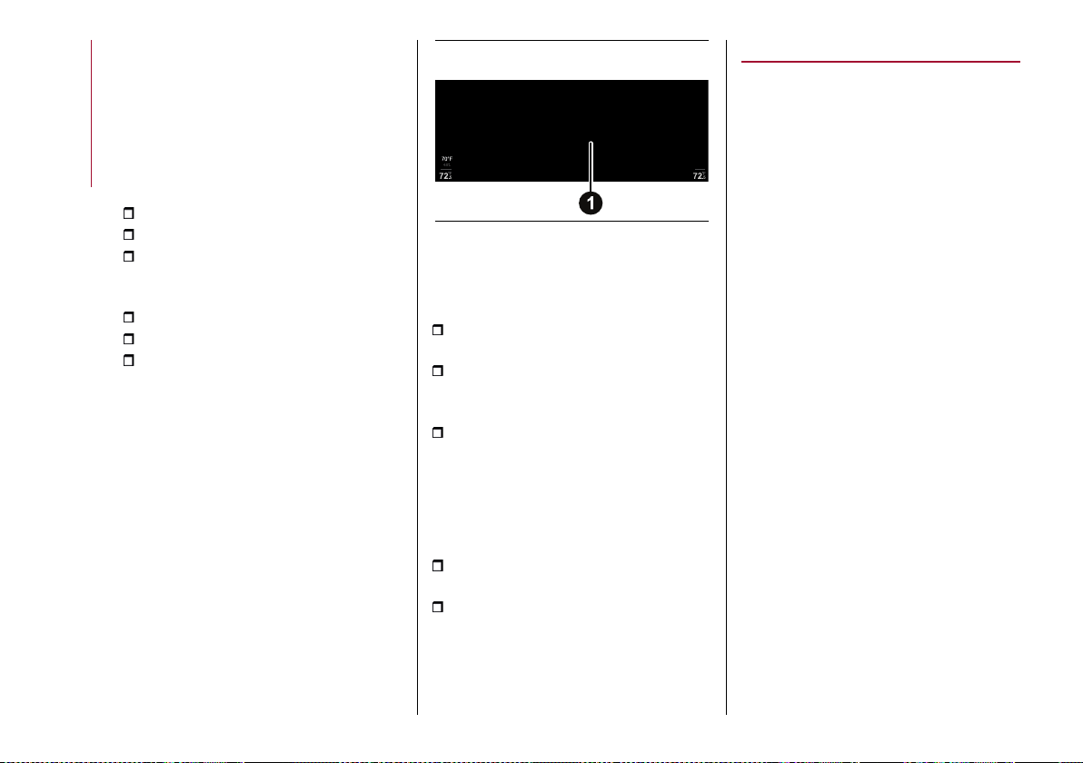
MULTIMEDIA
270
SYSTEM SETTINGS
After viewing the "Driver Assistance"
menu in full screen mode, a list of all
settings that can be made for driver
assistance systems will appear on the
display.
The information shown on the display is
as follows:
system identification icon;
system name;
graphicbutton1 fig.258 foractivating
("ON") and deactivating ("Off"") the
system;
indication of the function status;
graphic display area of the system;
default system setting (modifiable by
the driver).
The following active driver
assistance/safety systems will not be
available if you have selected the "RACE"
driving mode (Quadrifoglio versions
only). In this case, a dedicated pop-up
screen will appear on the Connect
system display.
258 12126V2096EM
SYSTEM ACTIVATION/DEACTIVATION
Using the touchscreen function
Proceed as follows:
press the display to select the desired
item;
to activate the system, press the
graphic button 1 fig. 258 rightwards: "ON"
will appear on the display
to deactivate the system, press the
graphic button 1 fig. 258 leftwards: "OFF"
will appear on the display.
Using the controls located on the
central tunnel
Proceed as follows:
turn the Rotary Pad and select the
desired item;
press on Rotary Pad to confirm
the choice and activate the system:
the selected item will be activated
automatically. When the system is
activated, press the Rotary Pad to
deactivate it.
Apple CarPlay and Android Auto
(where provided)
The Apple CarPlay and Android Auto
applications allow you to use your
smartphone in the car safely and
intuitively.
To activate them, simply connect a
compatible smartphone to the USB
port and the contents of the phone will
automatically appear on the display
of the Connect system after having
selected the default action the first time
you connect an Android and/or an iOS
device. Use the "Device Manager" menu
to change the choice previously made.
To check the compatibility
of your smartphone, see the
indications on the websites:
https://www.android.com/intl/it_it/auto/
and http://www.apple.com/it/ios/carplay/.
The first time a device is connected, a
pop-up screen appears on the Connect
system display, allowing you to choose
which profile to use it with during
subsequent connections. The possible
options are: “Charge Only”, “Media/iPod”,
“Projection mode”. The options can be
modified by using the "Device Manager"
menu.
If your smartphone is properly connected
to the car via the USB port, an additional
widget and its graphic icon will be
displayed on the Connect System Main
271
Menu on the left hand side of the status
bar.
To use Apple CarPlay, connect your
iPhone to the car using a MFI (made for
iPhone) certified USB cable.
To use Android Auto, connect your
smartphone to the car using a USB for
Android phones having appropriate
features. Using unsuitable cables may
prevent correct system operation.
NOTE Interaction with the smartphone
may be needed to enable Apple
Carplay/Android Auto and some other
functions. Complete the action on your
device (smartphone) as needed.
APP CONFIGURATION (Apple CarPlay)
Apple CarPlay is compatible with the
iPhone 5 or more recent models, with
the iOS 7.1 operating system or later
versions.
In order to use Siri in Apple CarPlay, you
must activate the function from your
smartphone settings.
To use Apple CarPlay, the smartphone
must be connected to the car by means
of a USB cable.
APP CONFIGURATION (Android Auto)
Before use, download the Android Auto
application to your smartphone from
Google Play Store.
The application is compatible with
Android 5.0 (Lollipop) and later versions.
To use Android Auto, the smartphone
must be connected to the car by means
of a USB cable.
INTERACTION
After the configuration procedure, when
you connect your smartphone to the
USB port on the car, after displaying the
pop-up screen and according to the last
setting made on the "Device Manager"
menu, the application will automatically
start on the Connect system.
The Rotary Pad can be used to select
and confirm the available smartphone
functions.
Multimedia contents on the smartphone
can be accessed directly via “MEDIA”
mode of Connect.
Interaction with voice controls
You can interact with the voice
assistants of Apple CarPlay and Android
Auto using the button
located on the
right side of the steering wheel:
long pressure will activate interaction
with the voice assistant of Apple (Siri) or
Android (Google Assistant);
short pressure will initiate interaction
with the native voice system. When
the voice assistant of the phone is
activated, the interface will but that of
the associated telephone not that of the
car. A short press will interrupt both the
native voice session and that of Siri or
Google Assistant.
WARNING If Apple CarPlay and
Android Auto apps are present, Siri
voice assistant (for Apple CarPlay) or
Google Assistant (for Android Auto) will
be activated. In this case you can use
"Natural language" voice controls and
not just the specific ones preset for the
Connect system. The voice assistants
of Siri (for Apple CarPlay) or Google
Assistant (for Android Auto) will only
be activated by holding the button
pressed on the right side of the steering
wheel.
Active Media or Phone mode
The following will be activated according
to how you press the button on the
right side of the steering wheel:
a short press of the button will
MULTIMEDIA
272
activate the voice control related to the
Connect system;
holding the button pressed to
activate the voice control for the phone
in "Projection" mode.
Active Tuner (Radio) or Navigation
mode
Briefly pressing the button on the
right side of the steering wheel on the
Connect system display to activates
the voice control for "Tuner (Radio)" or
"Navigation" mode, also when Apple
CarPlay or Android Auto apps are
activated.
NAVIGATION
With the Apple CarPlay and Android Auto
applications, you can choose to use the
navigation system on your smartphone.
The controls can be imparted directly on
the Connect system.
The user can choose to change their
selection at any time by accessing the
navigation system that they want to use
and setting a new destination.
EXITING FROM THE Apple CarPlay AND
Android Auto APPS
To end the Apple CarPlay or Android
Auto session, physically disconnect the
smartphone from the USB port on the
car.
VOICE CONTROLS
219)
WARNING For languages not supported
by the system, voice controls are not
available.
NOTE Voice controls activation is only
possible with the ignition device at ON.
Voice controls will not be active when
the starter is in the OFF position and the
Connect system is on.
NOTE If Apple CarPlay and Android Auto
apps are present, Siri voice assistant
(for Apple CarPlay) or Google Assistant
(for Android Auto) will be activated. In
this case you can use "Natural language"
voice controls and not just the specific
ones preset for the Connect system.
The voice assistants of Siri (for Apple
CarPlay) or Google Assistant (for
Android Auto) will only be activated by
holding the button pressed on the
right side of the steering wheel.
STARTING A VOICE SESSION
Briefly press the button on the
steering wheel once.
INTERRUPTING A VOICE SESSION
At any time during a voice session
(dialogue), you can press and hold the
button to stop and restart the voice
session from scratch and impart a new
command, regardless of the previous
conversation.
For example, if the system is uttering
a voice help message and recognises
the desired command, it may be useful
to stop the help by pressing the button
on the steering wheel and give the
command, so you don't have to wait for
the help messages to end.
DEACTIVATING A VOICE SESSION
With the voice session active, briefly
press the button on steering wheel.
The voice session will automatically
close when a command has been
recognised and no further actions are
required by the driver.
A phone call will also interrupt the voice
session, in order to allow you to answer
and speak normally using the hands-free
function.
RADIO AM/FM/DAB VOICE CONTROLS
The button activates the following
functions:
Tune to station <XXX>
Tune to station < XXX>
Tune to frequency < XXX>
Tune to frequency < XXX>
Add to favourites
Show available stations
Show list of available stations
Show favourite stations
Show the list of favourites stations
273
FM
AM
DAB
Radio controls ("Go to radio")
MEDIA VOICE CONTROLS
The button activates the following
functions:
Play (or say View) Album
Play (or say View) Artist
Play (or say View) Composer
Play (or say View) Genre
Play (or say View) Playlists
Play (or say View) Song
Play (or say View) All
Activate shuffle
Deactivate shuffle
Play Song (or Track)
Play All (or say View All) Albums
Play All (or say View All) Artists
Play All (or say View All) Composers
Play All (or say View All) Genres
Play All (or say View All) Playlists
Change to AUX
Pass to USB 1
Change Source to USB 2
Pass to USB 3
Change to AUX
Change Bluetooth
®
NOTE These controls are valid on
devices connected to the system via USB
ports and not through the Bluetooth
®
system.
PHONE VOICE CONTROLS
The button activates the following
functions:
Dial number <XXXXXX>
Call <XXXXXX>
Go (or say Change to phone)
Phone commands
Search contact
Search
Call back
Missed calls
All calls
Show contacts
View contacts
Show all messages
Send a message
Send a message to
Read last (or say Read the last)
message
NAVIGATION COMMANDS
(where provided)
The button activates the following
functions:
Go (or say Drive) Home
Favourite <favourite name>
Navigation commands
Go (or say Change) to Navigation
Set 2D map
Set detailed 3D map
Set overhead view
Add destination
Destination
Interrupt navigation
Repeat instructions
Show map
Enter city
Enter nation
Enter country
Enter street
Enter house number
Route preview
Find the closest <point of interest>
WARNING
219) Voice controls must always be given in
safe driving conditions, in compliance with
the laws in force in the country where you
are driving.
MULTIMEDIA
274
CONNECTED SERVICES - ALFA
CONNECT SERVICES
220)
(for versions/markets where provided)
Alfa Connected Services enrich
the experience of use of the car by
connecting it to the network.
The services (where provided) allow
you to receive timely assistance in
case of need and emergency, to obtain
information about the conditions of
your vehicle, its location, control it
remotely and to improve the navigation
experience (where provided) through
real-time updates.
You can access the Alfa Connect
Services using a dedicated mobile app
for smartphone, smart watche, web
portal or the Connect system of your car.
The availability of services is subject to a
Alfa Connect Services subscription.
More information on Alfa Connect
Services (applicability, availability,
compatibility, packages and
specifications) can be found on the
official Alfa Romeo website.
GENERAL DISCLAIMER
Personal data & privacy
FCA collects, processes and uses
the personal data of the vehicle in
accordance with legal requirements.
More information can be found in the
general conditions of service and on data
protection policies on the Alfa Romeo
official website.
The Customer is solely responsible for
using the services in the vehicle, even if
by other people, and shall inform all users
and occupants of the vehicle about the
services and the functions and limits of
the system.
If the SOS emergency service is
activated, the call will be automatically
routed to a private FCA Call Centre. We
hereby specify that, whenever the SOS
call is referred to the text, it is to be
considered managed by private service
providers.
Operating prerequisites
To use some of the Alfa Connect
Services you need to register on the
dedicated portal that can be accessed
from the Alfa Romeo official website,
activate and login to your devices.
Alfa Connect Services is not
available in all countries and is subject
to limitations depending on Connect
system type, location and duration of the
services.
The full operation of the Alfa Connect
Services, including SOS calls and
roadside assistance calls (ASSIST), is
subject to mobile network and GPS
geolocation coverage, without which
the proper provision of services is
not guaranteed. Coverage may not be
guaranteed in places such as tunnels,
garages, multi-storey car parks,
mountains.
In case of mobile network overload or
problems related to the power supply of
the vehicle (e.g. low battery), the services
may not be available.
When using the services, customers
shall keep their passwords secret for
strictly personal use and not to disclose
them to third parties.
SERVICES
According on the equipment of the car
and of the country, different services
may be available for different durations.
For further information about your car,
go to the personal page on the official
Alfa Romeo website.
Some of the packages made available to
the customer are:
My Assistant: Customer care and
safety alert service, which includes:
"SOS emergency call and ASSIST
roadside assistance" (see chapter
"In emergency").
275
"Vehicle Health Report":
information on the state and
condition of the car, notifying
potential maintenance needs to the
customer via periodic e-mails. This
service is provided on condition
that the Customer has previously
provided the FCA network with a
valid e-mail address.
"In-Vehicle Notifications":
possibility to receive messages
and/or notifications related to the
provision of services and reminder
messages about the execution of
service and/or recall campaigns on
the Connect system display.
You can contact FCA Customer
Service for further information
regarding the messages received.
My Car: vehicle status monitoring
service.
My Remote: management of services
which can be used remotely (switching on
lights, locking/unlocking doors, etc.).
My Navigation: connected navigation
service (subject to availability according
to version/market).
My Wi-Fi: Optional Wi-Fi Hotspot
service. This service provides Internet
access from the car to all devices with
Wi-Fi connection (smartphones, tablets,
laptops) (supported technologies: 3G –
4G). This creates a private Wi-Fi internet
access point in the car. The function,
available only with the ignition device in
ON position or with the engine started
allows the connection of up to eight
devices simultaneously, but not the
direct communication between devices.
The quality of the service offered by the
integrated Wi-Fi Hotspot depends on
the coverage of the mobile operator's
network.
NOTE The hotspot name and password
can only be changed with the starter in
the ON position.
You can enrich Alfa Connect Services
experience by purchasing optional
services for which a subscription is
required.
These can be subscribed to
independently by the customer from the
catalogue of services available for the
car, directly on the personal page of the
official Alfa Romeo website.
DEACTIVATION OF GEOLOCATION
MODE
(for versions/markets where provided)
If you wish to deactivate geolocation
mode, simply do so from the Connect
systemfig. 259 (seethe"Settings" menu
of the Connect system for more details).
When geolocation mode is deactivated
some of the services on mobile apps and
web that use the location of the car will
not be available.
UPDATING THE SYSTEM
Alfa Connect Services and the Connect
system application software are
updated remotely in order to provide
the customer with newer software
versions that include new features or
enhancements/enrichments of features
already offered.
Updates are made at the discretion of
FCA.
Some system updates will be
managed automatically, others will
be communicated to the Customer by
259 12126S2094EM
Turn off screen
Bright display
OFF
Restore App
Geolocation
Connected services
70.
F
5
°
70.
F
5
°
10:05
WARNING The
icon is shown at the
bottom left of the Connect system
display when the geolocation function
is active (ON). When geolocation is on,
the vehicle position is tracked to enable
the functions that require it. When
geolocation is off, the vehicle position is
only tracked by the navigation, safety,
insurance and driver assistance systems
(where provided). See the Connect
system "Settings" chapter to deactivate
the function.
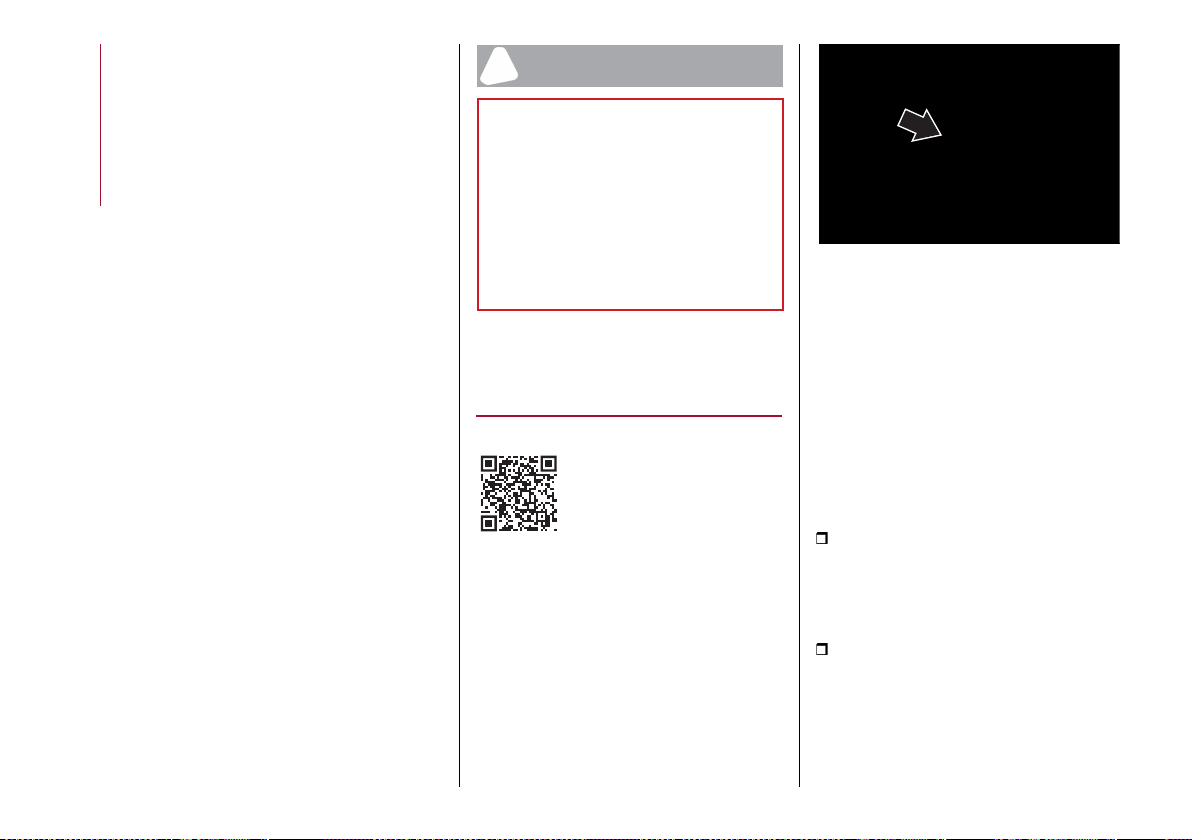
MULTIMEDIA
276
process still in progress, warning the
system will be temporary unavailable.
When updating the system, connected
services, including SOS calls and ASSIST
calls will not be available.
To obtain more information about
services, features, specifications,
availability and any updates please
always refer to the content included in
the official website of Alfa Romeo.
DEACTIVATION OF ALFA CONNECT
SERVICES
If you sell your car on which the Alfa
Connect Services are still active, you
will be responsible for logging off your
profile from the services on the page
on the official Alfa Romeo website, by
contacting the Customer Care or by
going to an Alfa Romeo dealership.
The customer is also responsible for
informing the new owner of any services
not yet expired associated with a new
Alfa Connect Services account.
WARNING
220) Always follow the highway code of
the country in which you are driving, and
concentrate on the road. Always drive
safely with your hands on the steering
wheel. Only use Connect system functions
when you are sure that it is safe to do
so. The customer is liable for all risks
associated with using the functions and
applications of the car. Failure to follow
these rules may cause serious accidents
and/or death.
WIRELESS CHARGING
SYSTEM– WCPM (Wireless
Charge Pad Module)
(where provided)
OPERATION
The wireless charger system is activated
automatically when a mobile phone
Qi® standard compatible is placed in
the appropriate housing,fig. 260, if the
mobile phone is compatible with Qi®
standard.
If the mobile phone is removed from the
housing during the wireless charging
phase, this will automatically be
interrupted.
260 11116S0999EM
The wireless charger system enables
charging when all doors are closed
properly and the engine has been
started.
Interacting with the wireless charging
system, positioning the mobile phone in
the appropriate housing, the following
messages are shown on the Connect
system display (with specific icons and
widgets), to inform the driver about the
wireless charging system status:
"Yourphone isbeingcharged", fig.261
andfig.262:isdisplayedwhenthe mobile
phone is positioned correctly in the
wireless charging compartment and the
system is activated correctly;
"Phone fully charged",fig.263:is
displayed when the phone has completed
charging its battery;
showing messages on the display of
the Connect allowing the customer to
confirm or postpone the update itself, up
to 20 times, after which installation will
start automatically.
Updates will be installed with the ignition
device in the STOP position.
If the update is still in progress the next
time the engine is started, the Connect
system will inform the customer of the
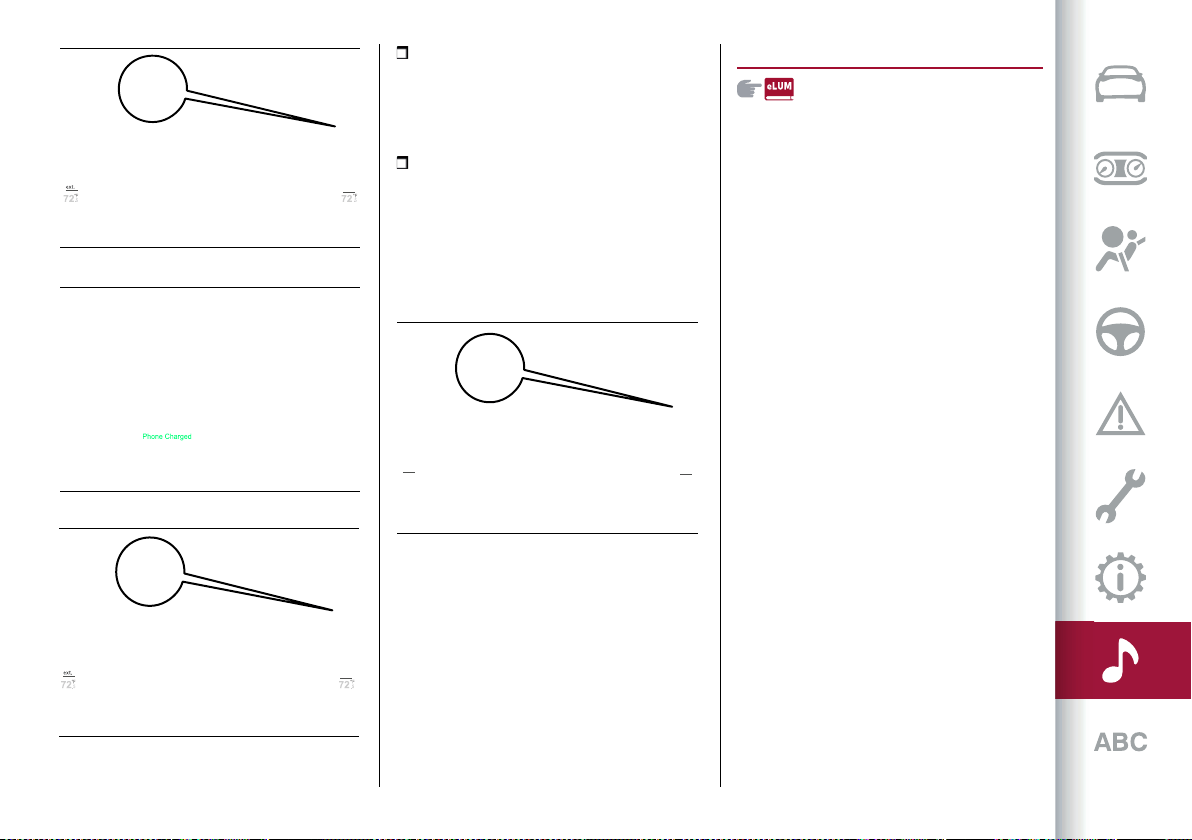
277
"Objectnot allowed", fig.264:is
displayed when a phone that is not
enabled for wireless charging or an
object that is not permitted (e.g. the
ignition key) is placed;
"Unavailable system",fig. 264:appears
when there is a malfunction in the
wireless charger system.
The driver can deactivate the display
of messages relating to the operating
status of the wireless charging system
the relevant Connect system menu.
OFFICIAL TYPE APPROVALS
All radio equipment supplied with the
vehicle complies with the 2014/53/EU
directive.
For further information visit
the www.mopar.eu/owner or
http://aftersales.fiat.com/elum/
websites.
261 12126S2085EM
262 12126S2088EM
263 12126S2086EM
264 12126S2087EM
Alberto’s iPhone
72.5
°F
72.5
°F
70.5°F
ext.
IMPORTANT INFORMATION AND RECOMMENDATIONS
WARNING
LUGGAGE COMPARTMENT
In the event of an accident or sharp braking, any object placed on the curtain may be projected into the passenger compartment, and risk hurting
the occupants.
INTERIOR FITTINGS
Do not travel with the storage compartment open: it may injure the front seat occupants in the event of an accident.
POWER SUPPLY
Modifications or repairs to the supply system that are not carried out correctly or do not take the system technical specifications into account can
cause malfunctions leading to the risk of fire.
ENVIRONMENTAL PROTECTION SYSTEMS
The catalytic converter and particulate filter (DPF) reach very high temperatures during operation. Therefore do not park the vehicle on flammable
materials (e.g. grass, dry leaves, pine needles, etc.): fire hazard.
IMPORTANT
LUGGAGE COMPARTMENT
To avoid damaging the blind, do not place heavy objects on it.

Ask your mechanic for
It’s in the heart of your engine.

Your car has chosen PETRONAS Selenia
The quality of PETRONAS Selenia is divided into a range of technologically advanced products:
SELENIA WR FORWARD 0W-30/0W-20
Fully synthetic, latest generation lubricant specifically formulated for EURO 6
diesel engines. Its fully synthetic formula and 0W-30 viscosity grade guaran-
tee excellent performance in terms of fuel economy for diesel engines
equipped with high efficiency turbo-charger. PETRONAS Selenia Forward
also features excellent resistance to oxidation, thus maintaining its technical
characteristics and promoting maximum engine performance throughout
the entire oil-change interval.
SELENIA DIGITEK P.E. 0W-30
Is the fully synthetic lubricant created for the most modern petrol engines.
Its special viscosity grade and its specific formulation enhance the fuel
economy features and, consequently the reduction of CO2 emissions.
Especially created for TwinAir two-cylinder engines, it ensures maximum
engine protection even under high mechanical stress due to mainly city use.
SELENIA MULTIPOWER C3
Is a high performance synthetic lubricant designed for petrol and diesel
engines requiring products able to reduce ash deposits to the absolute
minimum. It provides increased protection against wear and tear
and has excellent fuel economy characteristics. It protects the particle
filter (DPF) in diesel engines.
SELENIA SPORT POWER
Is a fully synthetic lubricant designed to enhance the sporting
characteristics of direct injection petrol engines (GDI).
It maximizes sporting performances while maintaining complete engine
protection, even under the most severe conditions of use.
The PETRONAS Selenia range is completed with Selenia StAR Pure Energy, Selenia StAR,
Selenia WR Pure Energy, Selenia Sport, and Selenia Racing.
For further information concerning PETRONAS Selenia products, consult the website: www.pli-petronas.com
The engine of your car was made with PETRONAS Selenia, the range
of engine oils that satisfies the most advanced international specifications.
Subject to specific tests and boasting outstanding technical characteristics,
PETRONAS Selenia is a lubricant designed to equip your engine
with reliable, winning performance standards”

NO TES


CONTENTS
ABS (Anti-Lock Brakes
System) . . . . . . . . . . . . . . . . . 80
ABSA (Active Blind Spot Assist)
System . . . . . . . . . . . . . . . . . 86
Active Cruise Control . . . . . . . . . 132
Active safety systems . . . . . . . . . . 80
AdBlue additive . . . . . . . . . . . . 158
®
Additive for diesel emissions AdBlue
(UREA) . . . . . . . . . . . . . . . . . 162
AFS function . . . . . . . . . . . . . . . . 26
Airbag
Front airbags . . . . . . . . . . . . . . 115
Side bags . . . . . . . . . . . . . . . . 115
Airbag (SRS supplementary restraint
system) . . . . . . . . . . . . . . . . . 115
Alarmsystem . . . . . . . . . . . . . . . 15
Alfa DNAsystem . . . . . . . . . . . . 128
ATV (Alfa Active Torque Vectoring)
system . . . . . . . . . . . . . . . . . . 80
Automatic dual-zone climate control
system . . . . . . . . . . . . . . . . . . 33
Automatic main beam
headlights . . . . . . . . . . . . . . . . 26
Automatic transmission . . . . . . . . 126
Automatic transmission gear lever
release . . . . . . . . . . . . . . . . . 193
Battery . . . . . . . . . . . . . . . . . . 208
Bodywork (cleaning and
maintenance) . . . . . . . . . . . . . 219
Bonnet . . . . . . . . . . . . . . . . . . . . 39
Brakes
Brake fluid level . . . . . . . . . . . 208
BSM (Blind Spot Monitoring)
system . . . . . . . . . . . . . . . . . . 84
Carrying children safely . . . . . . . . . 101
Changinga wheel . . . . . . . . . . . . 185
Checking levels . . . . . . . . . . . . . 208
Child restraintsystems . . . . . . . . . 101
Child safety device . . . . . . . . . . . . 16
Climate control system . . . . . . . . . 33
CO2 emissions . . . . . . . . . . . . . . 245
Connected Services - Alfa Connect
Services . . . . . . . . . . . . . . . . 274
Control panel and on-board
instruments . . . . . . . . . . . . . . 46
Controls on streering wheel Connect
system . . . . . . . . . . . . . . . . . 253
Controls on tunnel Connect
system . . . . . . . . . . . . . . . . . 250
Cruise Control . . . . . . . . . . . . . . . 131
DAA (Driver Attention Assist)
System . . . . . . . . . . . . . . . . . 95
Daytime running lights (DRL) . . . . . . 26
Demanding useofthe car . . . . . . . 196
Dimensions . . . . . . . . . . . . . . . . 231
Dipped beam headlights . . . . . . . . . 26
Dipped headlights (changing a
bulb) . . . . . . . . . . . . . . . . . . 173
Direction indicators (changing a
bulb) . . . . . . . . . . . . . . . . . . 173
Display . . . . . . . . . . . . . . . . . . . . 46
Doors . . . . . . . . . . . . . . . . . . . . 16
Driving assistance systems . . . . . . . 84
DTC (DriveTrainControl)
system . . . . . . . . . . . . . . . . . . 80
Dusk sensor . . . . . . . . . . . . . . . . 26
Easy Entry (function) . . . . . . . . . . 19
Electric parking brake . . . . . . . . . 124
Electric steering wheel heating . . . . 24
Electric sunroof . . . . . . . . . . . . . . 37
Electric windows . . . . . . . . . . . . . 36
Emergency starting . . . . . . . . . . . 190
Engine . . . . . . . . . . . . . . . . . . . 223
Engine coolant level . . . . . . . . 208
Engine compartment . . . . . . . . . . 208
EngineImmobilizer (system) . . . . . . 15
Engine oil
Consumption . . . . . . . . . . . . . 208
Level check . . . . . . . . . . . . . . 208
Engine run-in . . . . . . . . . . . . . . . 121
ESC (Electronic Stability Control)
system . . . . . . . . . . . . . . . . . . 80
Exterior lights . . . . . . . . . . . . . . . 26
FCW (Forward Collision Warning)
System . . . . . . . . . . . . . . . . . 87
Fluids and lubricants . . . . . . . . . . 240
Fog lights . . . . . . . . . . . . . . . . . . 26
Fog lights (bulb replacement) . . . . 173
Front light cluster with main
beam/dipped beam
halogen headlights (bulb
replacement) . . . . . . . . . . . . . 173

CONTENTS
Front light cluster with main
beam/dipped beam Xenon
gas discharge headlights (bulb
replacement) . . . . . . . . . . . . . 173
Front seats(electric adjustment) . . . 19
Front seats(electric heating) . . . . . . 19
Front seats (manual
adjustments) . . . . . . . . . . . . . . 19
Fuel consumption . . . . . . . . . . . . 245
Fuel cut-off system . . . . . . . . . . . 193
Fuseboxes . . . . . . . . . . . . . . . . 179
Fuses (replacement) . . . . . . . . . . 179
Hands Freemode (tailgate) . . . . . . 40
HAS (Highway Assist) system . . . . 138
Hazard warning lights . . . . . . . . . 170
Emergency braking . . . . . . . . . 170
HDC (Hill Descent Control)
system . . . . . . . . . . . . . . . . . . 80
Head restraints . . . . . . . . . . . . . . 23
Headlight alignment adjustment . . . 26
Headlight alignment corrector . . . . . 26
HSA (Hill Start Assist)system . . . . . 81
Identification data . . . . . . . . . . . 222
Ignition device . . . . . . . . . . . . . . . 13
Interior lights . . . . . . . . . . . . . . . . 30
ISC (Intelligent Speed Control)
System . . . . . . . . . . . . . . . . 147
ISOFIX child restraint system
(installation) . . . . . . . . . . . . . . 101
Jump starting . . . . . . . . . . . . . . 190
Keys
Electronic key . . . . . . . . . . . . . 13
Lane Change . . . . . . . . . . . . . . . . 26
Lane Departure Warning
System . . . . . . . . . . . . . . . . 150
LaneKeeping Assist System . . . . . 153
Light bulbs
Bulbtypes . . . . . . . . . . . . . . . 173
Light switch . . . . . . . . . . . . . . . . 26
Luggage compartment tailgate . . . . 40
Main beam headlights . . . . . . . . . . 26
Main beam headlights (changing a
bulb) . . . . . . . . . . . . . . . . . . 173
Occupant protection systems . . . . . 97
Paintwork (cleaning and
maintenance) . . . . . . . . . . . . . 219
ParkSensors system . . . . . . . . . . 148
Parking lights . . . . . . . . . . . . . . . 26
Parking the vehicle . . . . . . . . . . . 124
Passive Entry (system) . . . . . . . . . 12
PBA (Panic Brake Assist)
system . . . . . . . . . . . . . . . . . . 81
Performance (top speed) . . . . . . . 244
Power Lock (device) . . . . . . . . . . . 16
Prescriptions for handling the car at
the endofits life . . . . . . . . . . . 246
Pre-tensioners . . . . . . . . . . . . . . 100
Load limiters . . . . . . . . . . . . . 100
Rain sensor . . . . . . . . . . . . . . . . 31
Raising thevehicle . . . . . . . . . . . 218
RCP (Rear Cross Path
detection) . . . . . . . . . . . . . . . . 84
Rear Back-up Camera / Dynamic
Gridlines . . . . . . . . . . . . . . . . 156
Rear ceiling light . . . . . . . . . . . . . . 30
Rear seats . . . . . . . . . . . . . . . . . 19
Rear window wiper/washer . . . . . . . 31
Rear-view mirrors . . . . . . . . . . . . . 25
Recharging the battery . . . . . . . . 215
Refuelling . . . . . . . . . . . . . . . . . 236
Refuelling procedure . . . . . . . . . . 158
Refuelling the car . . . . . . . . . . . . 158
Regular checks . . . . . . . . . . . . . . 196
Replacing a bulb . . . . . . . . . . . . . 174
Replacing an external bulb . . . . . . 173
Rims and tyres . . . . . . . . . . . . . . 227
Rims and tyres provided . . . . . . . . 227
Run FlatTyres . . . . . . . . . . . . . . 190
Safe Hold . . . . . . . . . . . . . . . . . 124
Saving fuel . . . . . . . . . . . . . . . . 162
SBA (Seat BeltAlert)system . . . . . . 98
Scheduled servicing . . . . . . . . . . 196
Seat belts . . . . . . . . . . . . . . . . . . 97
Seats . . . . . . . . . . . . . . . . . . . . . 19
Servicing procedures . . . . . . . . . . 216
Side bag . . . . . . . . . . . . . . . . . . . 115
Side lights . . . . . . . . . . . . . . . . . . 26
Snow chains . . . . . . . . . . . . . . . 218
SOS call andASSIST call . . . . . . . 170
Speed Limiter . . . . . . . . . . . . . . 130
SRS(supplementary restraint
system) . . . . . . . . . . . . . . . . . 115

Start& Stop Evo . . . . . . . . . . . . 129
Startingthe engine . . . . . . . . . . . 122
Startingwithflat key battery . . . . . 14
Steering lock . . . . . . . . . . . . . . . . 14
Steering wheel . . . . . . . . . . . . . . . 24
Suggestions for driving . . . . . . . . 162
TC (Traction Control)system . . . . . 80
TFT reconfigurabledisplay . . . . . . . 48
The keys . . . . . . . . . . . . . . . . . . . 12
TJA (Traffic Jam Assist)
System . . . . . . . . . . . . . . . . 142
Towing thebroken-downcar . . . . . 193
Towing the car . . . . . . . . . . . . . . 193
Towing trailers . . . . . . . . . . . . . . 163
TPMS (Tyre Pressure Monitoring
System) . . . . . . . . . . . . . . . . . 92
TSR (Traffic Sign Recognition)
System . . . . . . . . . . . . . . . . 145
Tyre RepairKit . . . . . . . . . . . . . . 188
Tyres (inflation pressure) . . . . . . . 227
Vehicle identification number . . . . 222
Warning lightsandmessages . . . . . 53
Washer fluid for
windscreen/headlights . . . . . . 208
WCPMwireless chargersystem . . . . 42
Weights . . . . . . . . . . . . . . . . . . 233
Wheels and tyres . . . . . . . . . . . . 218
Window bag . . . . . . . . . . . . . . . . 115
Windscreen wiper . . . . . . . . . . . . . 31
Replacing blades . . . . . . . . . . 216
Windscreen wiper/washer . . . . . . . 31
Smart washingfunction . . . . . . . 31
INDEX OF MULTIMEDIA CONTENT
ABSA (Active Blind Spot Assist) System
DAA (Driver Attention Assist) System
HAS (Highway Assist) system
ISC (Intelligent Speed Control) System
LKA (Lane Keeping Assist) system
TSR (Traffic Sign Recognition) System
TJA (Traffic Jam Assist) System
Android Auto
Apple CarPlay
SOS call and ASSIST call

Navigation mode
Phone mode
Connected Services –
Alfa Connect Services
Widget
INDEX OF MULTIMEDIA CONTENT

FCA Italy S.p.A. - MOPAR - Technical Service Operations - Service Engineering
Largo Senatore G. Agnelli, 3 - 10040 Volvera - Torino (Italy)
Print no. 603.93.593 - 09/2019 - 1st Edition
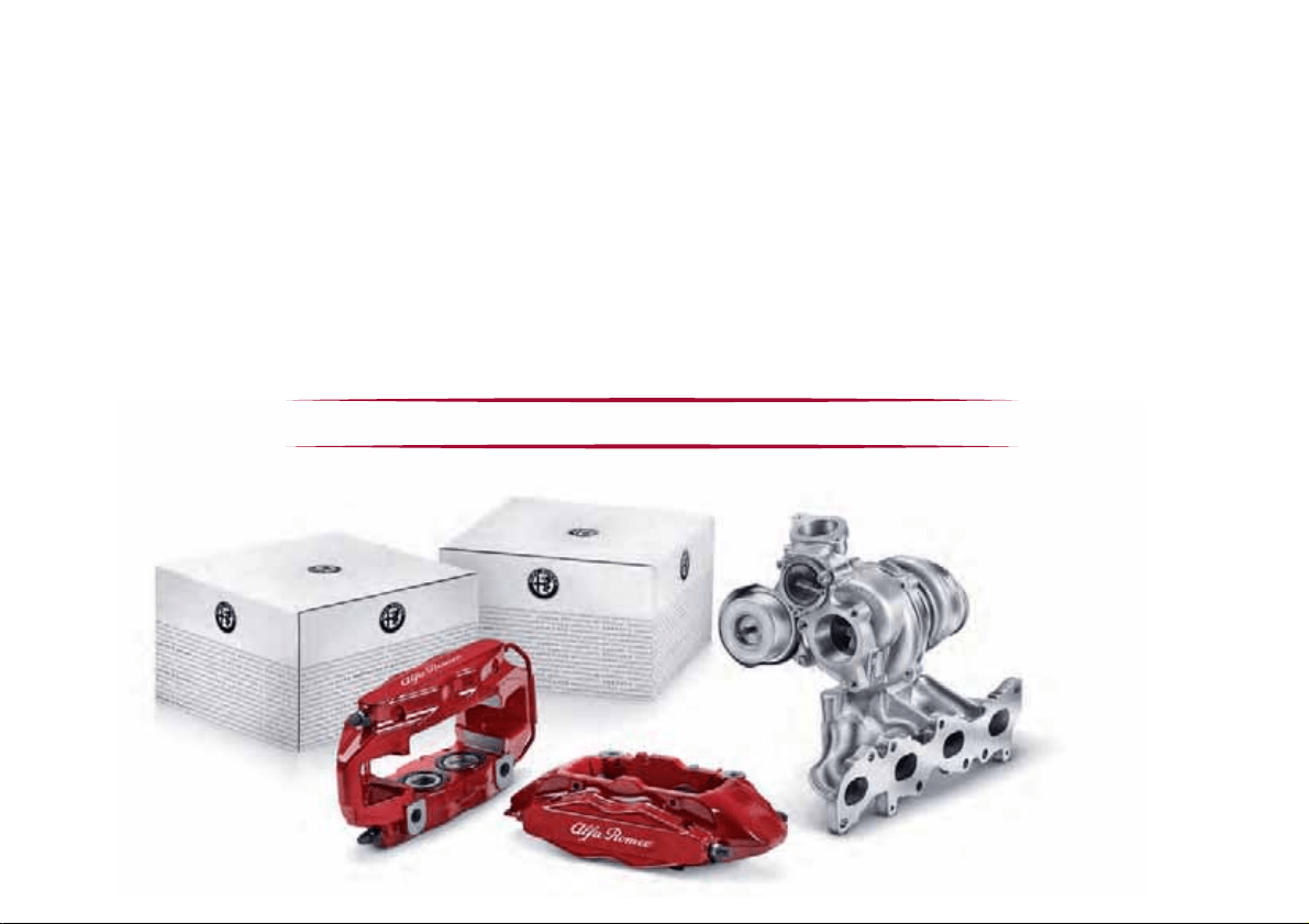
ALFA ROMEO GENUINE SPARE PARTS AND ACCESSORIES
PERFECT FOR YOUR VEHICLE, RIGHT DOWN TO THE SMALLEST DETAIL
The Alfa Romeo Genuine Spare Parts and Accessories follow the rigid component engineering and manufacturing specifi cations
used in the assembly line to meet the technical specifi cations of your new Alfa Romeo and to enhance its style and performance. They
undergo strict approval tests and quality controls to ensure they comply with safety and environmental standards.
All of the components on your new Alfa Romeo, from the smallest bulb to the most complex mechanical, electrical and electronic
systems, are designed to work in harmony and guarantee you a comfortable and safe drive, in full respect for the environment. The
Genuine Accessories fully enhance the style of your new vehicle.
Entrust the experience and quality of Alfa Romeo Dealerships to fi nd the full range of Alfa Romeo Genuine Spare Parts and
Accessories.
Find your nearest Dealership on www.alfaromeo.com

ENGLISH