Falcon PROP110EI5SS/CH Oven/Stove
Product's Documents
Below are documents related to this product, you can read online or download:
- Owner's manual - (English) Read Online | Download pdf

User Manual Falcon PROP110EI5SS/CH Oven/Stove

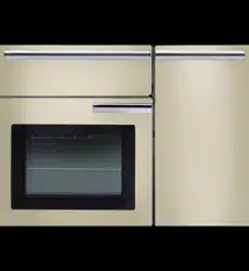
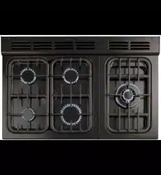
The 110 induction cooker (Fig.2-1) has the following features:
Use only pans that are suitable for induction hobs. We recommend stainless steel, enamelled steel pans or cast iron pans with enamelled bases. Note that some stainless steel pans are not suitable for use with an induction hob so please check carefully before purchasing any cookware.
Pans made of copper, aluminium or ceramic are not suitable for use on an induction hob. The kind of pan you use and the quantity of food affects the setting required. Higher settings are required for larger quantities of food.
Pots and pans should have thick, smooth, flat bottoms (Fig.2-2). This ensures the maximum heat transfer from the hob to the pan, making cooking quick and energy efficient. Never use a round-bottomed wok, even with a stand.

The very best pans have bases that are very slightly curved up when cold (Fig.2-3). If you hold a ruler across the bottom you will see a small gap in the middle. When they heat up the metal expands and lies flat on the cooking surface.

Make sure that the base of the pan is clean and dry to prevent any residue burning onto the hob panel. This also helps prevent scratches and deposits.
 Always use pans that are the same size as (or slightly larger than) the areas marked on the hob. Using a lid will help the contents boil more quickly. nn Always take care before touching the surface, even when the hob is turned off. It may be hotter than you think!
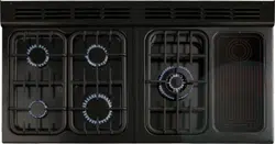
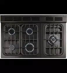
The induction hob comprises of five cooking zones containing induction elements with different ratings and diameters (Fig.2-4) each with a pan detector and residual heat indicator, and a hob control display.

The hob control display (Fig.2-5) informs you of the following induction hob functions:
 Pan detector
 Residual heat indicator
 Automatic heat-up
 Child lock

IMPORTANT: After use, switch off the hob element by its control and DO NOT RELY on the pan detector.
If a cooking area is switched on and there is no pan in place or if the pan is too small for the cooking area, then no heat will be generated. The symbol will appear on the hob control display; this is the “pan-missing symbol”. Place a pan of the correct size on the cooking area and the symbol will disappear and cooking can begin. After 10 minutes without detecting a pan the cooking zone will switch off automatically.
Table 2-1 shows the minimum pan sizes recommended for each cooking zone.

Note: Using pans with a base diameter smaller than those recommended will result in a power reduction.
After use, a cooking zone will remain hot for a while as heat dissipates. When a cooking zone is switched off the residual heat indicator symbol , will appear in the display. This shows that the cooking zone temperature is above 60 °C and may still cause burns. Once the temperature has dropped to below 60 °C thewill go out.
This function is available on all of the cooking areas. It allows rapid heating up of the element to bring the selected cooking zone up to temperature. Once the zone is at the required cooking temperature the power level will reduce automatically to the preset level.
The function is selected by turning the control knob to the A’ position. This can be selected by either turning the control knob momentarily anti-clockwise from the zero position or clockwise past the ‘9’ until the symbol is shown on the hob control display. Once theis displayed, turn the control knob to the level of your choice (1 to 9). The pan will heat up at 100% power for a specified time before the power is reduced to the level selected.
When the Automatic Heat-up function is activated, the hob control display will flash alternately between the setting and the chosen power level.
Once the automatic heat-up time has ended the hob control display will stop flashing and will display the chosen power level.
The Automatic Heat-up function can be stopped by either turning the control knob back to the “0” power setting or turning the control knob to the “9” power setting.
For your guidance Table 2-2 shows the time available at power depending on the power level selected in the Automatic Heat-up mode.

To prevent the unwanted use by children, the hob can be locked.
IMPORTANT: This can only be activated when all the cooking zones are switched off.
To lock the hob, first turn on any of the hob controls on then off – this will activate the hob display – then simultaneously turn both rear outer induction controls anti-clockwise (Fig.2-6) until appears in the hob control display for all cooking areas.

This will NOT affect the ovens or grill; they can still be used.
To unlock the hob, simultaneously turn both rear outer induction controls anti-clockwise until the symbol disappears.
This is an integrated pan protection feature, designed to minimise overheating of the cookware. This function identifies when the temperature of the pan rises rapidly and works to maintain a safe level of pan temperature. It should not interfere with normal cooking.
Please remember not to leave the hob unattended. Care should be taken to not allow your cookware to boil dry.
Open the door and pull the grill pan (Fig.2-7) or carriage (Fig.2-8) forward using the handle.

The grill has two elements that allow either the whole area of the pan to be heated or just the right-hand half.
Adjust the heat to suit by turning the knob. To heat the whole grill, turn the knob clockwise (Fig.2-9).

To heat the right-hand half, turn the knob anti-clockwise. The neon indicator light by the grill control will come on.
For best results, leave the grill pan in the grill chamber and preheat the appropriate part(s) of the grill for two minutes.
The grill trivet can be removed and the food placed on it while you are waiting for the grill to preheat.
DO NOT leave the grill on for more than a few moments, without the grill pan underneath it, otherwise the knobs may become hot.
Once the grill has preheated, take the grill pan out again and put the trivet back in place with the food on it. Slide the grill pan or carriage back into the grill chamber. Make sure that it is pushed right in.
Accessible parts may be hot when the grill is in use. Young children should be kept away.
The grill pan trivet can be turned over to give two grilling positions (Fig.2-10).

Never close the grill door when the grill is on.
DO NOT leave the grill on for more than a few moments, without the grill pan underneath it, otherwise the knobs may become hot.
The clock must be set to the time of day before the right- hand oven will work. See the following section on ‘The Clock’ for instructions on setting the time of day.
References to ‘left-hand’ and ‘right-hand’ ovens apply as viewed from the front of the appliance.
The left-hand oven is a conventional zoned oven and the right-hand oven is a programmable fanned oven.
Conventional Zoned Ovens
A conventional oven has two heating elements – one visible in the top of the oven and the other under the oven base.
Note: Be careful to avoid touching the top element and element deflector when placing or removing items from the oven.
Fan ovens
Fanned ovens circulate hot air continuously, which means faster, more even cooking. The recommended cooking temperatures for a fan oven are generally lower than those for a non-fan oven.
Operating the Ovens
Turn the oven knob to the desired temperature (Fig.2-11).

The oven indicator light will glow until the oven has reached the temperature selected. It will then cycle on and off during cooking.
When cooking foods with high water content, there may be some steam visible at the grille at the rear of the hotplate.
This is perfectly normal.
Oven Shelves
In addition to the flat shelves some models are supplied with a drop shelf (Fig.2-41). The drop shelf increases the possibilities for oven shelf spacing.

The oven shelves can be easily removed and refitted.
Pull the shelf forward until the back of the shelf is stopped by the shelf stop bumps in the oven sides (Fig.2-42).
Lift up the front of the shelf so the back of the shelf will pass under the shelf stop and then pull the shelf forward (Fig.2-43).

To refit the shelf, line up the shelf with a groove in the oven side and push the shelf back until the ends hit the shelf stop. Lift up the front so the shelf ends clear the shelf stops, and then lower the front so that the shelf is level and push it fully back (Fig.2-44).

The Handyrack (Left-hand Oven)
The Handyrack (Fig.2-45) fits to the left-hand oven door only. Food cooking on it is easy to attend to, because it is accessible when the door is open.

The maximum weight that can be held by the Handyrack is 5.5 kg (12 lb). It should only be used with the supplied roasting tin, which is designed to fit the Handyrack. Any other vessel could be unstable.
It can be fitted at two different heights. One of the oven shelves must be removed and the other positioned to suit.
When the Handyrack is used in its highest position, other dishes can be cooked on the bottom shelf position or base of the oven.
When the Handyrack is used in its lowest position, other dishes can be cooked on the second shelf position or base of the oven.
To fit the Handyrack, locate one side of it on the door bracket (Fig.2-46). Then spring the other side out to clip it onto the other bracket (Fig.2-47).

Main Oven Light
Press the button to turn the light on (Fig.2-48).

If the oven light fails, turn off the power supply before changing the bulb. See the ‘Troubleshooting’ section for details on how to change the bulb.
If you have not used an induction cooker before please be aware of the following:
If you want to cook more than one dish, choose dishes that require approximately the same cooking time. However, dishes can be ‘slowed down’ slightly by using small containers and covering them with aluminium foil, or ‘speeded up’ slightly by cooking smaller quantities or placing them in larger containers.
Very perishable foods such as pork or fish should be avoided if a long delay period is planned, especially in hot weather.
DO NOT place warm food in the oven to be timed. DO NOT use a timed oven that is already warm. DO NOT use the timed oven if the adjoining oven is already warm.Whole poultry must be thoroughly defrosted before being placed in the oven. Check that meat and poultry are fully cooked before serving.
The wire shelves should always be pushed firmly to the back of the oven.
Baking trays with food cooking on them should be placed level with the front edge of the oven’s wire shelves. Other containers should be placed centrally. Keep all trays and containers away from the back of the oven, as overbrowning of the food may occur.
For even browning, the maximum recommended size of a baking tray is 340 mm (131⁄2”) by 340 mm (131⁄2”).
When the oven is on, do not leave the door open for longer than necessary, otherwise the knobs may get very hot.
Isolate the electricity supply before carrying out any major cleaning. Allow the cooker to cool.
Never use paint solvents, washing soda, caustic cleaners, biological powders, bleach, chlorine based bleach cleaners, coarse abrasives or salt. Do not mix different cleaning products – they may react together with hazardous results.
All parts of the cooker can be cleaned with hot soapy water but take care that no surplus water seeps into the appliance.
Remember to switch the electricity supply back on and reset the clock before reusing the cooker.
Daily Care
First of all make sure that all heat indicator lights are off and that the cooking surface is cool. Apply a small dab of ceramic cleaning cream in the centre of each area to be cleaned. Dampen a clean paper towel and work the cream onto the cooking surface. As a final step, wipe the cooking surface with a clean, dry paper towel.
Cleaning Spills
For spills and boil-overs that occur while cooking, turn the unit off and wipe the area surrounding the hot zone with a clean paper towel. If a spill (other than a sugary substance) is on the hot zone, do not clean until the unit has completely cooled down, and then follow the instructions below ('Cleaning burned-on spills’).
If you accidentally melt anything on the surface, or if you spill foods with a high sugar content (preserves, tomato sauce, fruit juice, etc.), remove the spill IMMEDIATELY with a razor scraper, while the unit is still hot.
IMPORTANT: Use an oven glove to protect your hand from potential burns.
Scrape the major spill or melted material from the cooking zone and push into a cold area. Then, turn the unit ‘OFF’ and allow it to cool before cleaning further. After the cooking surface cools down and the heat indicator lights go off, follow the ‘Daily Care’ procedure outlined above.
Cleaning Burned-on Spills
Make sure that the heat indicator lights are off and that the hob is cool. Remove the excess burned-on substance with a single-edged razor scraper. Hold the scraper at an angle of about 30° to the surface and then scrape off the burned-on matter (Fig.5-1).

Once you have removed as much as possible with the scraper, follow the ‘Daily Care’ procedure outlined above.
The grill pan and grid should be washed in hot soapy water.
After grilling meats or any foods that soil, leave to soak for a few minutes immediately after use. Stubborn particles may be removed from the grid using a nylon brush. Alternatively, the grill pan can be washed in a dishwasher.
Before you remove any of the grill parts for cleaning, ensure that they are cool, or use oven gloves. DO NOT use any abrasive substances.Removing the Glide-out Grill Pan
The glide-out grill pan can be easily removed for cleaning as follows. Remove the grill pan support frame by pulling the grill pan forward (Fig.5-2).

Lift the grill pan clear of the support frame. The support frame is held to the side rails by two clips on each side (Fig.5-3).

For each side, support the side rail with one hand and with the other hand lift the frame up and out of the side clips (Fig.5-4).

For safety, push the side rails back into the grill chamber.
If you need to remove the side rails to allow cleaning of the grill chamber, you can unhook them from the grill chamber sides (Fig.5-5) and wipe the sides clean with a soft cloth and mild detergent.

DO NOT put the side runners in a dishwasher.
Once you have finished, hook the side rails back onto the sides of the chamber. To refit the frame, pull the side rails forward and, for each side in turn, support the side rail and press the frame down into the side rails. Replace the grill pan.
When refitting the grill pan, ensure that the wide rim is at the front (Fig.5-6).

Control Panel and Doors
Avoid using any abrasive cleaners, including cream cleaners, on brushed stainless steel surfaces. For best results, use a liquid detergent or multi-purpose cleaner.
The same cleaner can also be used on the doors. Alternatively, use a soft cloth wrung out in clean hot soapy water. You can use the same method for cleaning the control panel and knobs. After cleaning, polish with a dry cloth.
The oven door front panels can be taken off so that the glass panels can be cleaned. Move the cooker forward to gain access to the sides (see the ‘Moving the Cooker’ section under ('Installation’).
Open the oven door slightly and remove the front panel fixing screws from the door sides, two each side (Fig.5-7).

Carefully lift off the outer door panel. The inside face of the glass panels can now be cleaned – take care not to disturb or wet the door insulation.
Note: If the door is triple glazed then the inner two panels are fixed together and should not be separated. After cleaning, carefully refit the outer door panel and replace the side fixing screws.
DO NOT use harsh abrasive cleaners or sharp metal scrapers to clean the oven door glass since they can scratch the surface, which may result in shattering of the glass.
Cook & Clean' Panels
The ovens have side ‘Cook & Clean’ panels which have been coated with a special enamel that partly cleans itself. This does not stop all marks on the lining, but helps to reduce the amount of manual cleaning needed.
These panels work better above 200 °C. If you do most of your cooking below this temperature, occasionally remove the panels and wipe with a lint free cloth and hot soapy water. The panels should then be dried and replaced and the oven heated at 200 °C for about one hour. This will ensure that the panels are working effectively.
Removing the Panels to clean the Enamel
Interior
If you wish to clean the enamel interior of the oven, you will first need to remove the shelves.
Each side of the oven is fixed with four fixing screws. You do not have to remove the screws to remove the oven panels.
Simply lift each side panel upwards, slide them off the screws and then pull them forwards (Fig.5-8).

Once the panels have been removed, the oven enamel interior can be cleaned.
DO NOT use steel wool, oven cleaning pads, or any other materials that will scratch the surface.
Interference with and repairs to the hob MUST NOT be carried out by unqualified persons. Do not try to repair the hob as this may result in injury and damage to the hob. Please arrange for repair by a suitably competent person.
Note: The induction hob is able to self-diagnose a number of problems and can show this information to the user via the hob control display. Error codes may be displayed if your hob has developed a fault.
If you appliance reports an error or is not working, you may be able to correct the fault by consulting the following.
Error code E2 is displayed
The electronic unit is too hot. Please check the installation of the cooker, making sure that there is sufficient ventilation. I n extreme cases, if a cooking utensil has been allowed to boil dry this error code may also be displayed. If in doubt please contact your installer or a qualified repair engineer.
No display operation
Over voltage or loss of supply voltage to the cooker. If in doubt please contact your installer or a qualified repair engineer.
Error code ERxx or Ex is displayed
The appliance has developed an internal technical fault that cannot be rectified by the user. Please contact your installer or a qualified repair engineer.
The fuse blows or the RCD trips regularly
Please contact your installer or a qualified repair engineer.
The hob will not switch on
Has the wiring system in the house blown a fuse or tripped an RCD?
Has the hob been correctly connected to the mains supply?
Has the child lock been activated? Please refer to the child lock section for details of this function.
The induction hob is noisy
When using the induction hob there may be some noise’ emitted from the pan. This is normal and may be most noticeable when cooking on high power settings or if 5 pans are used simultaneously. The type of pan may also contribute to induction ‘noise’.
The cooling fan
The induction hob incorporates a cooling fan. This cooling fan is active when either the grill or ovens are on. Under certain conditions, the cooling fan may remain active when the grill or ovens are switched off. This is normal and the fan will switch off automatically.
A crack has appeared in the hob surface
Disconnect the cooker immediately from the power supply and arrange for its repair. Do not use the cooker until after the repair.
My hob is scratched
Always use the cleaning methods recommended in this guide, and ensure that the pan bottoms are smooth and clean.
Marks from mineral deposits from water or food can be removed with a cleaning cream. However, tiny scratches are not removable but will become less visible in time as a result of cleaning.
The oven fan is noisy
The note of the oven fan may change as the oven heats up – this is perfectly normal.
Grill not cooking properly
Are you using the pan and trivet supplied with the cooker? Is the pan being used on the runners, not the floor of the compartment? Is the grill tray pushed back fully to the ‘back stop’ position?
The knobs get hot when I use the oven or grill. Can I avoid this?
Yes, this is caused by heat rising from the oven or the grill, and heating them up. Do not leave the oven door open. Make sure that the grill pan is pushed right back to the ‘back stop’ when grilling. Always grill with the grill compartment door open.
If there is an installation problem and I don’t get my original installer to come back to fix it, who pays?
You do. Service organisations will charge for their call- outs if they are correcting work carried out by your original installer. Therefore, it’s in your own interest to keep track of this installer so that you can contact them as required.
Power failure
In the event of a failure in the electrical supply, remember to reset the clock to ensure that the timed oven continues to operate.
Food is cooking too slowly, too quickly, or burning
Cooking times may differ from your previous oven. Check that you are using the recommended temperatures and shelf positions – see the oven cooking guide. Then adjust the settings according to your own individual tastes.
The oven is not cooking evenly
Do not use a baking tray with dimensions larger than those specified in the section on ‘General Oven Tips’.
If you are cooking a large item, be prepared to turn it round during cooking.
If two shelves are used, check that space has been left for the heat to circulate. When a baking tray is put into the oven, ensure that it is placed centrally on the shelf.
Check that the door seal is not damaged and that the door catch is adjusted so that the door is held firmly against the seal.
A dish of water when placed on the shelf should be the same depth all over. (For example, if it is deeper at the back, then the back of the cooker should be raised up or the front lowered.) If the cooker is not level, arrange for your supplier to level it for you.
The timed oven is not coming on when turned on manually
Is the power on? Is the clock illuminated? If not, there may be something wrong with the power supply. Is the cooker supply on at the isolator switch?
Has the time of day been set?
Is the key symbol () showing in the display to signify that the oven is locked? See the ‘Clock’ section of the instructions for more information on the key lock feature.
The timed oven is not coming on when automatic cooking
Has the oven knob been left in the OFF position by mistake? Is the oven locked (see above)?
Oven temperature getting hotter as the cooker gets older
If turning the temperature down using the oven control knob has not worked, or has only worked for a short time, then you may need a new thermostat. This should be fitted by a service person.
The oven light is not working
The bulb has probably blown. You can buy a replacement bulb (which is not covered under the guarantee) from most electrical stores. Ask for an Edison screw fitting 15 W 240 V lamp, FOR OVENS (Fig.6-1). It must be a special bulb, heat resistant to 300 °C. See the HELP leaflet for spares by mail order.
Before removing the existing bulb, turn off the power supply and make sure that the oven is cool. Open the oven door and remove the oven shelves.
Locate the bulb cover and unscrew it by turning it anti- clockwise - it may be very stiff (Fig.6-2).

Taking care to protect your fingers with a glove in case the bulb should shatter, unscrew the old bulb.
Screw in the new bulb clockwise and then screw the bulb cover back on. Turn on the electricity supply and check that the bulb now lights.
The oven door is misaligned
The bottom hinge of either oven door can be adjusted to alter the angle of the door (Fig.6-3). Loosen the bottom hinge fixing screws and use the notch and a flat bladed screwdriver to move the position of the hinge to set the hinge position (Fig.6-4). Retighten the hinge screws.

The diagram (Fig.7-1) shows the minimum recommended distance from the cooker to nearby surfaces as given in AS 5601 / AG 601.

1. Overhead – Measurement A
The minimum height of any surface above the cooker is mm above the hotplate.
Range hoods and exhaust fans shall be installed in accordance with the manufacturer’s instructions. However, in no case shall the clearance between the highest part of the hob of the cooking appliance and a range hood be less than mm or, for an overhead exhaust fan, 750 mm.
2. Side Clearances – Measurements B & C
Where B, measured from the periphery of the nearest burner to any vertical combustible surface, or vertical combustible surface covered with toughened glass or sheet metal, is less than 200 mm, the surface shall be protected to ensure that the combustible surface does not exceed 65 °C above ambient*. Even with the surface protected, the dimension B should not be less than 135 mm above hotplate level.
The fixing of 5 mm thick ceramic tiles to the surface, or attaching fire resistant material to the surface and covering with sheet metal with a minimum thickness of 0.4 mm to a height C of not less than 150 mm above the hotplate, should satisfy this requirement.
3. Side Clearances – Measurement D & E
Where D, the distance from the periphery of the nearest burner to a horizontal combustible surface is less than mm, then E shall be 10 mm or more, or the horizontal surface shall be above the trivet.
DO NOT place the cooker on a base.
A clearance of 130 mm is required if the cooker is near a corner of the kitchen, to allow the oven doors to open. The actual opening of the doors is slightly less, but this allows for some protection of your hand as you open the door.
We recommend a gap of 1110 mm between units to allow for moving the cooker. Do not box the cooker in – it must still be possible to move the cooker in and out for cleaning and servicing.
Moving the Cooker
On no account try and move the cooker while it is plugged into the electricity supply.The cooker is very heavy, so take great care. DO NOT use the door handles or control knobs to manoeuvre the cooker.We recommend two people manoeuvre the cooker. Ensure that the floor covering is firmly fixed, or removed to prevent it being disturbed when moving the cooker around.
From the back tilt the cooker forward and remove the rear half of the polystyrene base pack (Fig.7-2). Repeat from the front and remove the front half of the poly base.

Now LOWER THE TWO REAR ROLLERS. First fit the levelling tool on the hexagonal adjusting nut, at both the front bottom corners of the cooker (Fig.7-3). Make 10 complete (360°) turns clockwise (Fig.7-4). (This means turning and removing the levelling tool 20 times.)


Unfold the rear edge of the cardboard base tray. Open the grill door and right-hand oven door so that you can get a good grip on the bottom of the fascia panel as you move the cooker.
Grip under the fascia panel and lift the front of the cooker slightly (Fig.7-5).

DO NOT use the door handles or control knobs to manoeuvre the cooker.
Carefully push the cooker backwards off the pack base and remove the cardboard base tray. Position the cooker close to its final position, leaving just enough space to get behind it.
It is recommended that you use a spirit level on a shelf in one of the ovens to check for level.
Place the cooker in its intended position, taking care not to twist it within the gap between the kitchen units as damage may occur to the cooker or the units.
The front feet and rear rollers can be adjusted to level the cooker. To adjust the height of the rear of the cooker use the levelling tool supplied to turn the adjusting nuts at the front bottom corners of the cooker. To set the front feet turn the bases to raise or lower.
This appliance must be installed by a qualified electrician to comply with the relevant regulations (AS/NZS and also the local electricity supply company requirements.
Ensure that the mains characteristics (voltage, nominal, power, etc.) match the ratings indicated on the data plate affixed to the cooker.
The cooker is preset for a single-phase earthed electrical connection. It is essential to install a multi-pole circuit breaker that completely disconnects the appliance from the mains, with a minimum contact break distance of 3 mm.
Current Operated Earth Leakage Breakers
The combined use of your induction cooker and other domestic appliances may cause nuisance tripping, so we recommend that the cooker is protected on an individual RCD (Residual Current Device) or RCBO (Residual Current Breaker with Overload).
IF IN DOUBT, PLEASE CONSULT A SUITABLY QUALIFIED ELECTRICIAN.
WARNING: THIS APPLIANCE MUST BE EARTHED
The appliance must be connected to an efficient earthing circuit. If the electricity network is not equipped with an earth connection, then it must be installed separately in compliance with local regulations.
Earthing is a safety measure required by law, and must be performed with particular care by a qualified technician, who must also check that the electricity supply characteristics are correct.
The total electrical load of the appliance is approximately kW. The cable size used should be suitable for this load and comply with all local requirements (i.e. PVC Insulated cable IEC 60227 – code 53 for ordinary cables).
Access to the mains terminal is gained by removing the electrical terminal cover box on the back panel. Connect the mains cable to the correct terminals for your electrical supply type (Fig.7-6 and Fig.7-7). Check that the links are correctly fitted and that the terminal screws are tight. Secure the mains cable using the cable clamp.


Fixed Wiring
For connection to fixed wiring, i.e. flexible conduit, remove the electrical terminal cover box on the back panel.
Undo the two screws and remove the blanking plate from the bottom flange of the cover box. Replace it with the new plate and then fit the cover box extension (Fig.7-8).

Fix the conduit bracket to the centre upright (Fig.7-9). Fit the conduit up to the bracket and secure in place with the plastic nut.

Connect the mains cable to the correct terminals for your electrical supply type (Fig.7-10 and Fig.7-11). Check that the links are correctly fitted and that the terminal screws are tight.


Replace the electric terminal cover box; make sure that the conduit is clear of the bottom flange.
Connection
If you need to move the cooker once it has been connected, make sure it is switched off at the supply switch before gripping under the fascia panel and lifting the front of the cooker slightly (Fig.7-5). Check behind the cooker to ensure that the electricity cable is not caught. As you progress, always ensure that the cable has sufficient slack to allow the cooker to move.
Make sure to release the stability chain as you ease the cooker out. Do not forget to refit it when you replace the cooker.
When you replace the cooker, check behind it again once more to ensure that the electricity cable is not caught or trapped.
Check each cooking zone in turn. Be sure to use pans of the correct size and material.
Turn on the grill control and check that the grill heats up.
Set the clock as described earlier, and then turn on the ovens.
Check the oven fans start to turn and that the ovens heat up.
Remove the 4 mm Allen screws from the doors (Fig.7-12).

Fit the door handles and secure using the 4 mm screws (Fig.7-13). nn The handles should be above the fixings.

Remove the 4 mm Allen screws from the top corners of the fascia (Fig.7-14). Fit the front handrail in position and secure using the 4 mm screws.

Classic & Professional+ models
Loosen the three screws along the front bottom edge of the cooker. Hook the central keyhole over the central screw. Twist and fit each end keyhole over their respective screws. Tighten the fixing screws (Fig.7-15).

Toledo model
Fit the inner plinth to the bottom front of the cooker using the 5 screws provided (Fig.7-16).

Fit the outer plinth (2 screws, 1 each end) to the inner plinth.
The height of the outer plinth can be adjusted by sliding it up or down via the slotted hole (Fig.7-17).

The cooker can be installed with or without the supplied splashback.
Position the splashback on the rear of the hotplate and secure with the screws supplied (Fig.7-18).

Installer: Please complete your details in this Guide, inform the user how to operate the cooker and hand oven the instructions.
Disconnect the cooker from the electricity supply before servicing, particularly before removing any of the following: control panel, side panels, ceramic hob, or any of the electrical components or cover boxes.
Before reconnection, check that the appliance is electrically safe.
1. To Remove a Side Panel
Disconnect from electricity supply.
Pull the cooker forward. Pull off the control panel end caps at each end of the panel (Fig.8-1). Remove the fixing screws under the end caps.

Remove the retaining screws for each panel (one at the front, two at the rear, and one at each lower front corner of the side panels).
Reassemble in reverse order.
2. To Lift up the Ceramic Hob
Disconnect from electricity supply.
Pull off the push fit control panel end caps at each end and remove the end fixing screws under the end cap.
Remove the lower front retaining screws (one each side) situated beneath the lower edge at the front corners of the side panels.
Swing the side panels to gain access to the hob fixing screws each side) at the top front of the side uprights.
Remove these screws.
Lift up the ceramic hob at the front and prop into position with a non-metallic prop.
CAUTION: The ceramic hob material is much more sensitive to scratches on the underside than the top.
Take care not to touch or scratch the underside of the ceramic as this will weaken the material and cause the top to shatter.
3. To Remove the Control Panel
Classic only: Remove the handrail by unscrewing the 2 end bracket fixing screws (Fig.8-2).

Pull off the control panel end caps at each end of the panel (Fig.8-1). Remove the fixing screws under the end caps.
Pull off all the control knobs. Open the grill and right-hand oven door and remove the control panel fixing screws underneath the control panel. The screws directly below the clock are for the clock fixing bracket, so do not remove them at this stage.
Lift the control panel, pull forward and disconnect the wiring from the rear.
Reassemble in reverse order. When replacing leads, refer to the wiring diagram in this manual. Check the operation of the timer.
Servicing nn Disconnect the cooker from the electricity supply before servicing, particularly before removing any of the following: control panel, side panels, ceramic hob, or any of the electrical components or cover boxes. nn Before reconnection, check that the appliance is electrically safe.
4. To Replace a Hob Element
Disconnect from electricity supply.
Lift up the ceramic hob (see 2). The Induction Heating Elements (IHE) are now accessible. Note the wire connection positions and element orientation for re-assembly. Disconnect the 4 wires, and remove the element unit and the 3 springs.
Fit the new sealing ring around the fan vent (Fig.8-3) and refit the 3 springs. Re-assemble in the reverse order.

Note: The IHE will require commissioning when the hob has been refitted.
5. To Replace the Light Switch
Disconnect from electricity supply.
Remove the control panel (see 3).
Note: The old switch may be destroyed during removal. Remove the old switch from its bezel by gripping the switch body behind the control panel and twisting sharply. Remove the switch bezel by folding back its locking wings and pushing forward. Fit the new bezel to the control panel by first lining up the raised key on its body with the cut-out in the control panel and pushing it in from the front.
Assemble the new switch to the bezel by lining up the key sections and pushing home. Fit the new button by pushing in from the front.
Replace the Control Panel in reverse order and test for correct operation.
6. To Remove the Electronic Timer
Disconnect from electricity supply.
Remove the control panel (see 3). Pull off the timer control button(s).
Remove the timer/mounting bracket assembly from the control panel by removing the fixing screws.
Remove the timer from its mounting bracket by depressing the plastic lugs on the timer case, at the same time pulling the unit forward.
Reassemble in reverse order. When replacing the leads, refer to the wiring diagram in this manual.
Check the operation of the timer.
7. To Replace the Grill Controller
Disconnect from electricity supply.
Lift up the hob and remove the control panel (see 2 and 3).
Disconnect the wiring from the controller. Remove the two screws holding the controller to the mounting panel. Fit the new controller and reassemble in reverse order. Check for correct operation.
8. To Remove Grill Element
Disconnect from electricity supply.
Remove the grill pan from the grill compartment. Undo the two screws and washers in the grill roof and remove the enamelled front shield.
Undo the 2 screws and washers securing the grill element front support. Remove the screws from the grill elements.
Lift the elements out carefully and, noting their position, disconnect the leads from the element terminals.
If it is not possible to disconnect the leads in this way, pull the cooker forward to gain access to the rear. Undo the screws securing the electric cover to the back sheet and remove the cover. Disconnect the terminals from the rear.
Fit new elements and reassemble in the reverse order. Check the operation of the grill.
9. To Remove the Grill Door
Remove the left-hand side panel (see 1). Remove the control panel (see 3). Remove the centre cover strip (5 screws, 2 top, 2 bottom, 1 in middle). Remove the two countersunk screws (1 each side) securing the grill hinge arms to the front of the grill chamber.
Note: The arms are spring tensioned. Carefully remove the grill door. Retain the gaskets.
Reassemble in reverse order, ensuring that the gasket is fitted between the hinge arm and the front of the grill chamber.
Remove the two screws and washers securing the grill element front support. Remove the screws from the grill element.
Lift the element out carefully, disconnecting the leads from the element terminals (noting their position). If it is not possible to disconnect the leads in this way, pull the cooker forward to gain access to the rear, remove the screws securing the electric cover to the back sheet, remove the cover and disconnect the terminals from the rear.
Fit the new element and reassemble in reverse order. Check the operation of the grill.
10. To Replace an Oven Door
Open the oven door. Support the door and remove the two screws securing the upper hinge and gasket to the cooker front (Fig.8-4). Remove the door from the lower hinge by lifting slightly and moving outwards (Fig.8-5).

The door is heavy, so take care.
Reassemble in reverse order.
11. To Adjust an Oven Door Angle
The bottom hinge of either oven door can be adjusted to alter the angle of the door (Fig.8-6). Loosen the bottom hinge fixing screws and use the notch and a flat bladed screwdriver to move the position of the hinge to set the hinge position (Fig.8-7).


12. Retighten the hinge screws.
To Replace an Oven Door Outer Panel
Move the cooker forward to gain access to the sides.
Open the oven door slightly and remove the front panel fixing screws from the door sides – two each side (Fig.8-8). Carefully lift off the outer door panel.

Remove the door handle from the panel by unscrewing the two retaining nuts. Fit the door handle to the new panel.
Fit the panel to the door. Reassemble in reverse order.
13. To Change an Oven Door Latch
Remove the outer door panel (see 12). Remove screws ‘B’ that hold the latch assembly to the inner door panel (Fig.8-9). Fit the new catch and reassemble in reverse order.
Verify the door operation.
14. To Adjust an Oven Door Catch Keep
Open the oven door, and slacken off the locknut at the base of the keep (Fig.8-10).
Screw in or out as required until the required fit is obtained. Retighten the locking nut.

15. To Replace an Oven Door Seal
Open the oven door. The seal has small hooks that hold it in place by locating into holes in the rear door face on the main oven and oven front face on tall oven. At the corner, pull the seal diagonally away from the door centre until the hook is released (Fig.8-11). Proceed to the next hook and release it in a similar way, and so on.

You can use force if the hooks are stiff, as the old seal will be discarded.
Carefully lift away the inner back. Reassemble in reverse order making sure that the four screws and washers are fully tightened.
16. To Replace a Thermostat
Disconnect from the electricity supply.
Lift the ceramic hob and remove the control panel (see 2 & 3). Open the oven door. Remove the oven furniture.
For the right-hand oven, remove the thermostat phial cover two screws). Unclip the thermostat phial from the clips in the oven back.
For the left-hand oven, pull cooker forward to gain access to the cover box at the rear of the cooker. Remove the four screws securing the cover and lift clear.
Feed the thermostat capillary out of the oven. Disconnect the wiring from the thermostat. Remove two screws holding thermostat to mounting panel. Fit new thermostat and reassemble in reverse order. Ensure that the phial is clipped to the oven back with the phial centrally positioned between the clips.
Check the operation of the thermostat.
17. To Remove an Oven Element Thermal Cut-out
Disconnect from electricity supply.
Pull the cooker forward to gain access to the cover box. Undo the cover screws and lift clear. The cut-out is located on the earth plate beside the oven element connections. Disconnect the cut-out wiring. Undo the fixings that secure the cut-out to the earth plate and remove. Fit the replacement control and re-assemble in reverse order.
18. To Remove an Oven Inner Back
Disconnect from electricity supply.
Open the door and remove the shelves. Remove the screws and washers securing the inner back to the back of the oven (Fig.8-12). Carefully lift away the inner back. Reassemble in reverse order making sure that the screws and washers are fully tightened.

19. To Remove the Fan Oven Element
Disconnect from electricity supply.
Remove the oven inner back (see 18). Remove the two screws from the top of the element and the one from the bottom of the element inside the oven (Fig.8-13).

Lift the element out carefully, disconnecting the terminals connected to the element (noting their positions).
If it is not possible to disconnect the leads in this way, pull the cooker forward to gain access to the rear.
Remove the screws securing the electric cover to the back sheet, remove the cover and disconnect the terminals from the rear.
20. To Replace an Oven Fan
Disconnect from electricity supply.
Pull the cooker forward to gain access to the rear. Remove the screws securing the electric cover to the back sheet and remove the cover.
Disconnect the three terminals connected to the fan noting their position. Remove the oven inner back (see 20). Hold the fan blade and remove the centre nut (left-hand thread) two brass washers, fan blade and circlip. Unscrew the fan retaining nuts and washers (three off each) and lift the fan away from the rear of the cooker. Fit the new fan and reassemble in reverse order.
Check the operation of the oven.
21. To Change Oven Light Bulb
Disconnect from electricity supply.
Make sure the oven is cool. Open the oven door and remove the oven shelves. Remove the grill pan and support from the grill chamber.
Unscrew the bulb cover by turning anti-clockwise. It may be very stiff (Fig.8-14).
Taking care to protect your fingers in case the bulb should shatter, unscrew the old bulb.
Fit an Edison screw fitting 15 W 240 V lamp, FOR OVENS. It must be a special bulb, heat resistant to 300 °C (Fig.8-15).

Screw in the new bulb, and then screw back the bulb cover.
Turn on the electricity supply and check that the bulb now lights.