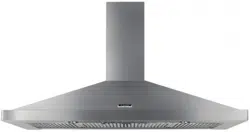
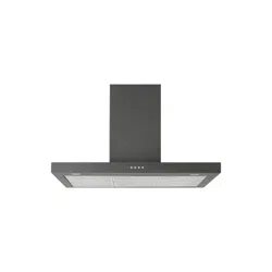
User Manual for Rangehood
RECOMMENDATIONS AND SUGGESTIONS
 The Instructions for Use apply to several versions of this appliance. Ac cordingly. you may find descriptions of individual features that do not ap ply to your specific appliance.
INSTALLATION
- The manufacturer will not be held liable for any damages resulting from incorrect or improper installation.
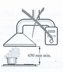
- The minimum safety distance between the cooker top and the extractor hood is 650 mm.
- Check that the mains voltage corresponds to that indicated on the rating plate fixed to the inside of the hood.
- For Class | appliances. check that the domestic power supply guarantees adequate earthing.
Connect the extractor to the exhaust flue through a pipe of minimum di ameter 120 mm. The route of the flue must be as short as possible.
- Do not connect the extractor hood to exhaust ducts carrying combustion fumes (boilers. fireplaces. etc.).
- If the extractor is used in conjunction with non-electrical appliances (e.g. gas burning appliances). a sufficient degree of aeration must be guaran teed in the room in order to prevent the backflow of exhaust gas. The kitchen must have an opening communicating directly with the open air in order to guarantee the entry of clean air.
USE
- The extractor hood has been designed exclusively for domestic use to eliminate kitchen smells.
- Never use the hood for purposes other than for which it has ben designed.
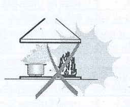
- Never leave high naked flames under the hood when itis in operation.
- Adjust the flame intensity to direct it onto the bottom of the pan only. mak ing sure that it does not engulf the sides.
- Deep fat fryers must be continuously monitored during use: overheated oil can burst into flames.
- The hood should not be used by children or persons not instructed in its correct use.
- The appliance is not intended for use by young children or infirm persons without supervision.
- Young children should be supervised to ensure that they do not play with the appliance.
MAINTENANCE
- Switch off or unplug the appliance from the mains supply before carrying out any maintenance work.
- Clean and/or replace the Filters after the specified time period.
- Clean the hood using a damp cloth and a neutral liquid detergent.
CHARACTERISTICS
Dimensions
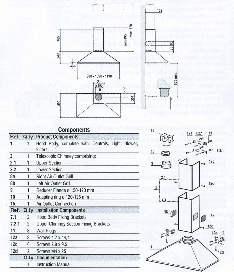
INSTALLATION
Wall drilling and bracket fixing
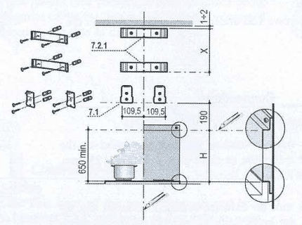
Wall marking:
- Draw a vertical line on the supporting wall up to the ceiling. or as high as practical. at the centre of the area in which the hood will be installed.
- Draw a horizontal line at 650 mm above the hob for installation without the back panel. or at height H (height of the visible part of the panel) for installation with the back panel.
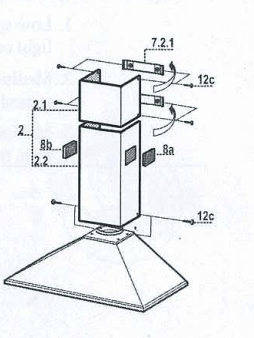
- Place bracket 7.2.1 on the wall as shown about 1-2 mm from the ceiling or upper limit. aligning the centre (notch) with the vertical reference line.
- Mark the wall at the centres of the holes in the bracket.
- Place bracket 7.2.1 on the wall as shown at X mm below the first bracket (X = height of the upper chimney section supplied). aligning the centre (notch) with the vertical line.
- Mark the wall at the centres of the holes in the bracket.
- Place bracket 7.1 as shown 109. mm from the vertical reference line and 190 mm above the horizontal reference line.
- Mark the centres of the holes in the bracket.
- Repeat this operation on the other side.
REAR PANEL (OPTIONAL)
The Rear Panel must be fitted before fixing the hood body and. if it is to be fixed at both top and bottom. must be fitted at the correct height prior to installing the bases. As this operation is rather complex. it should be carried out either by the kitchen installer or a qualified person who knows the final dimensions of the units.
For fixing at the top only. proceed as follows:
- Rest the back panel on the base. inserting the lower plate between the upper surface and the wall. centring it on the vertical reference line.
- Mark the centres of the two holes in the upper plate.
- Drill ¢ 8 mm holes at all the centre points marked.
- Insert the wall plugs 11 in the holes.
- Fix the brackets using the 12a screws supplied.
- Fix the back panel (where present) using the 12a screws supplied.
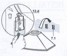
Mounting the hood body
- Screw the two screws 12d supplied onto the brackets 7.1.
- Hook the hood body onto the bracket 7.1. centring it around the vertical line.
- Use the adjusting screws 12d underneath the hood to level the hood body.
Connections
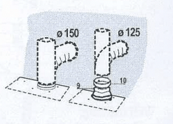
DUCTED VERSION AIR EXHAUST SYSTEM
When installing the ducted version. connect the hood to the chimney using either a flexible or rigid pipe ¢ 150 or 125 mm. the choice of which is left to the installer.
- To install a g 125 mm air exhaust connection. insert the re ducer flange 9 on the hood body air outlet and the adapting ring 9120-125 10 on the reducer flange.
- Fix the pipe in position using sufficient pipe clamps (not sup plied).
- Remove any activated charcoal filters.
RECIRCULATION VERSION AIR OUTLET
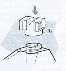
- Push fit the air outlet fitting 15 onto the air outlet of the hood body.
- Ensure that the activated charcoal filters have been inserted.
ELECTRICAL CONNECTION
- Connect the hood to the mains through a two-pole switch hav ing a contact gap of at least 3 mm.
- Remove the grease filters (see paragraph Maintenance) being sure that the connector of the feeding cable is correctly inserted in the socket placed on the side of the fan.
Chimney assembly
Upper chimney section
- Slightly widen the two sides of the upper chimney and hook them behind the brackets 7.2.1. making sure that they are prop erly housed.
- Secure the sides to the brackets using the 4 screws 12¢ (2. x 9.5) supplied.
Lower chimney section
- Slightly widen the two sides of the section and hook them be tween the upper section and the wall. making sure that they are properly housed.
- Fix the sides of the bottom section to the hood body using the 2 screws 12c (2. x 9. ) supplied.
- When installing the recirculation version. fit the directional grills 8a — 8b in their housings so that the directional symbols are at the top and towards the front of the hood. Ensure that they are inserted correctly in the outlet connection piece 15.
USE
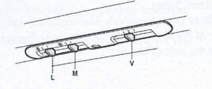
| L. |
Light |
Switches the lighting system on and off |
| M |
Motor |
Switches the extractor motor on and off |
| V |
Speed |
Sets the operating speed of the extractor:
1. Low speed. used for a continuous and silent air change in the presence of light cooking vapour.
2. Medium speed. suitable for most operating conditions given the optimum treated air flow/noise level ratio.
3. Maximum speed. used for eliminating the highest cooking vapour emis sion. including long periods.
|
MAINTENANCE
Grease filters
CLEANING METAL GREASE FILTERS
The filters are washable at least every 2 months of operation. or more frequently for particularly heavy usage.
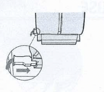
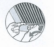
- Remove the filters one at a time. supporting them with one hand and turning the safety knobs (pull and turn).
- Wash the filters. taking care not to bend them. Allow them to dry before refitting.
- Replace them and fix them using the safety knobs provided (pull and turn).
Activated charcoal filter (Recirculation version)
These filters are not washable and cannot be regenerated. and must be replaced approximately every 4 months of operation. or more frequently with heavy usage.
REPLACING THE ACTIVATED CHARCOAL FILTER
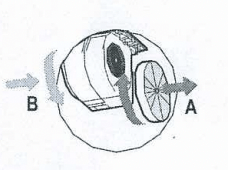
- Remove the metal grease filters
- Remove the saturated activated charcoal filter as shown (A).
- Fit the new filters (B).
- Replace the metal grease filters.
Lighting
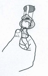
LIGHT REPLACEMENT
20W halogen light.
- Remove the 2 screws fixing the Lighting support. and pull it out of from the Hood.
- Extract the lamp from the Support.
- Replace with another of the same type. making sure that the two pins are properly inserted in the lamp holder socket holes.
- Replace the Support. fixing it in place with the two screws re moved as above.
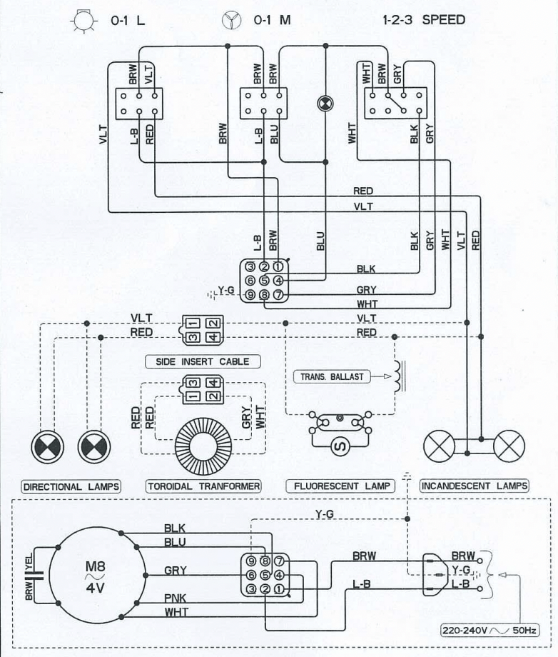
Electric Diagram