Loading ...
Loading ...
Loading ...
ENGLISH
E
29
RS-232C command table
How to read the command table
Command: Command field (See page 25.)
Direction: W When the “Parameter” is set in the parameter field (see page 25), the command functions as described
under “Control/Response Contents”.
R The returned value indicated under “Reply” can be obtained by setting “????”, “
?” or “???+”
(repeater control) in the parameter field (see page 25).
Parameter: Parameter field (See page 25.)
Reply: Response (Returned value)
*: “Yes” indicates commands which can be used in power standby mode.
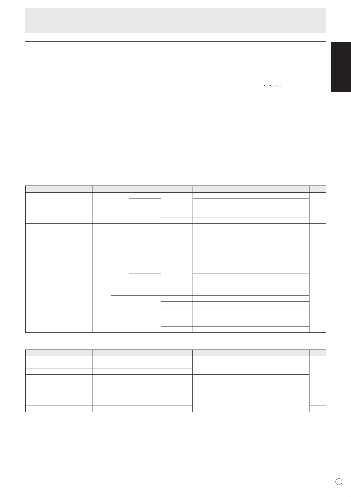
Power control/Input mode selection
Function
Command Direction
Parameter Reply Control/Response contents *
POWER CONTROL POWR W 0
Switches to standby mode.
Yes
1 Returns from standby mode.
R 0 Standby mode
1 Normal mode
2 Input signal waiting mode
INPUT MODE SELECTION
INPS W 0 Toggle change for input mode
Terminals not selected in DVI SELECT/BNC SELECT cannot be
selected.
Yes
1 PC1 DIGITAL
“ERR” when AV (DIGITAL) is selected for DVI SELECT.
2 PC2 ANALOG
3 AV2 COMPONENT
“ERR” when PC (ANALOG) is selected for BNC SELECT.
4 AV3 VIDEO
6 PC3 ANALOG
“ERR” when AV (COMPONENT) is selected for BNC SELECT.
7 AV1 DIGITAL
“ERR” when PC (DIGITAL) is selected for DVI SELECT.
R 1 PC1 DIGITAL
2 PC2 ANALOG
3 AV2 COMPONENT
4 AV3 VIDEO
6 PC3 ANALOG
7 AV1 DIGITAL
SCREEN menu (PC2/PC3)
Function
Command Direction
Parameter Reply Control/Response contents *
AUTO
ASNC W 1 No
CLOCK CLCK WR 0-255 0-255
No
PHASE PHSE WR 0-63 0-63
POSITIONING POSITION OF
THE LONGEST
DIRECTION
HPOS WR 0-500 0-500 A maximum value depends on a resolution.
POSITION OF
THE SHORTEST
DIRECTION
VPOS WR 0-100 0-100
RESET ARST W 1 No
Controlling the Monitor with a PC
Loading ...
Loading ...
Loading ...