Projector
LP-WU9750B
User's Manual
Thank you for purchasing this product. Please
read this manual before you operate your
projector. Save it for future reference.
English
Français
Deutsch
Español
Português
P

English - 2
INDEX
Warning, Notices and Safety Instructions 4
Notice 4
Do not open 4
Description pertaining to FCC Rules Part 15 4
About Waste Electrical and Electronic Equipment 5
Sun light Warning 5
Never look into the projector light source directly 5
Electric shock 5
Do not overload wall outlets/extension cords 6
Cleaning 6
Dampness, smoke, steam, dust, high temperature and direct
exposure to sunlight 6
Ventilation 6
Intrusion of foreign objects 6
Carrying the projector 6
Please install the projector on an even and stable surface 7
Servicing 7
Changing parts 7
Power cord 7
Notices you should read prior to the installation of the
projector 8
Take frequent breaks to let your eyes rest 8
Installation environment for the projector 8
Protect the projector with care 8
Keep the projector's ventilation inlets and outlets free from
obstructions 8
Caution for 3D 10
LASER WARNING 11
CLASS 3R LASER PRODUCT 11
Laser Parameters 11
Product labels 12
Location of laser aperture 15
Interlock switches 15
Name and quantity of toxic/hazardous substances/elements
contained in the product 16
Projector parts and functions 17
Front view 17
Rear view 18
Bottom view 20
Range of effective remote control signal reception 21
Installing batteries in the remote control 21
Installation the projector. 22
1. Orient the projector towards the screen 22
2. Remove the lens PU foam on the projector 22
3. Depending on your area, to select the correct input
voltage. 22
4. Connect the power cord to the projector 22
6. Starting the projector up. 23
7. Adjusting the projector's angle, Lens Shift, Zoom and
Focus 23
8. Correcting keystoning caused by projection angle 23
9. Turning off the projector 24
Throw distance 25
Modes of installation 25
Front Tabletop 25
Front Ceiling 26
Rear Tabletop 26
Rear Ceiling 26
RRear projection - submersive installation 26
Horizontal and vertical lens shift 27
Moving the lens vertically 27
Moving the lens horizontally 27
Connecting the projector to other devices 28
HDMI / DVI connection 28
12V Trigger connection 28
RGB connection 29
HDBaseT connection 29
SDI connection 30
Turning on the projector 30
Changing OSD language 30
Adjusting screen orientation 31
Front Ceiling 31
Rear Tabletop 31
Rear ceiling 32
Adjusting the projector lens 32
Remote control 33
OSD Menu Tree 35

English - 3
OSD Description 38
MAIN 38
Input 38
PinP 39
PinP Selection 39
PinP Position 39
Color Space 40
3D 40
Magnify & Shift 40
No Signal 40
PICTURE 41
Picture Mode 41
Contrast 42
Color 42
Tint 42
Sharpness 42
Color Temperature 44
White Balance 44
Aspect 45
Over Scan 46
Position and Phase 46
Auto Adjust 47
LASER 48
Power Mode 48
Power Level 48
High Altitude 49
ADVANCED 50
Installation 50
Lens Control 50
Lens Memory 51
Lens Centering 51
Gamma 51
Pattern 51
Blanking 53
Edge blending 53
Memory 55
Dynamic Black 55
SETUP 56
Network 56
OSD Setting 57
Infrared Remote 57
Remote ID 57
Start up logo 57
Trigger 57
Auto Search 58
Auto Power Off 58
Direct Power On 58
Language 58
AMX D.D. 58
Web control/ Crestron Control 58
SERVICE 59
Model Name 59
Serial Number 59
Software Version 1 / 2 59
Active Source 59
Signal Format 59
Laser Hours 60
Thermal Status 60
Lens Information 60
Factory Reset 60
Cleaning 61
Cleaning the Cabinet 61
Cleaning the Lens 61
Using the Kensington
®
Lock 62
Simple troubleshooting 63
64
LED STATUS 65
Power LED 65
Supported Signal Input Modes 67
SDI formats 68
3D Timing Format 68
Dimensions 69
Communication settings 70
RS-232 Communication 70
Connection 70
1. Protocol 71
2. Command format 71
3. Response code / Error code 72
Communication command table 75
Copyright information 88
Copyright 88
Disclaimer 88
Trademark 88
Warranty and after-service 88
English - 4
Warning, Notices and Safety Instructions
Warning, Notices and Safety Instructions
Notice
This product is intended for the adults who have the ability to operate this machine.
Please write down your projector model number and serial number and keep the information for
maintenance purposes in the future. Should the equipment be lost or stolen, the information could also
be used for the police report.
Model number:
Serial number:
missing accessory, contact your dealer immediately.
1. AC Power Cord US 125V*1 4. Remote control *1 7. Printed Manual*1 10. WEEE Manual *1
2. AC Power Cord EU*1 5. AA battery *2 8. EAC Document *1 11. RS232 cable(cross) *1
3. Wire Remote Cable*1 6. CD-ROM *1 9. EU Recycle Sheet *1
Do not open
CAUTION
RISK OF ELECTRIC SHOCK
DO NOT OPEN
The lightning flash with an arrowhead within a triangle
is intended to tell the user that inside this product
may cause risk of electrical shock to persons.
The exclamation point within a triangle is intended to tell
the user that important operating and/or servicing instructions
are included in the technical documentation for this equipment.
CAUTION / TO REDUCE THE RISK OF ELECTRIC SHOCK
DO NOT REMOVE COVER(OR BACK)
NO USER-SERVICEABLE PARTS INSIDE
REFER SERVICING TO QUALIFIED SERVICE PERSONNEL
This is a Class A product. In a domestic environment this product may cause radio interference in
which case the user may be required to take adequate measures.
Description pertaining to FCC Rules Part 15
This device complies with Part 15 of the FCC Rules. Operation is subject to the following two
conditions: (1) this device may not cause harmful interference, and (2) this device must accept any
interference received, including interference that may cause undesired operation.
This device has been tested and found to comply with the limits for a Class A digital device, pursuant
to Part 15 of the FCC Rules. These limits are designed to provide reasonable protection against
harmful interference in a residential installation.
This equipment generates, uses and can radiate radio frequency energy. If not installed and used in
accordance with the instructions, may cause harmful interference to radio or television reception.
However, there is no guarantee that interference will not occur in a particular installation. If this
equipment does cause interference to radio or television reception, which can be determined by
turning the equipment off and on, the user is encouraged to try to correct the interference by one or
the following measures:
Reorient or relocate the receiving antenna.
Increase the separation between the equipment and receiver.
Consult the dealer or an experienced radio/TV technician for help.
English - 5
Warning, Notices and Safety Instructions
CAUTION:
operate the equipment.
This Class A digital apparatus meets all requirements of the Canadian ICES-003 Standards.
Cet appareil numérique de la classe A est conforme à la norme NMB-003 du Canada.
About Waste Electrical and Electronic Equipment
The mark is in compliance with the Waste Electrical and Electronic Equipment Directive
2002/96/EC (WEEE).The mark indicates the requirement NOT to dispose the equipment including
any spent or discarded batteries or accumulators as unsorted municipal waste, but use the return and
collection systems available. If the batteries or accumulators included with this equipment, display the
chemical symbol Hg, Cd, or Pb, then it means that the battery has a heavy metal content of more than
0.0005% Mercury or more than, 0.002% Cadmium, or more than 0.004% Lead.
Sun light Warning
Avoid using this projector in direct sun light.
Sun light on the projector lens can severely damage the Digital Mirror Devices (DMD™).
Never look into the projector light source directly
When turn on the projector, make sure nobody's eye will effects by the projection of light.
Always avoid to let eyes contact to the light.
As with any bright source, do not stare into the direct beam, RG2 IEC 62471-5:2015
Electric shock
To protect your projector, avoid turning on the projector during lightning storms and unplug it from
the wall outlet. This will prevent sudden electrical surges caused by the lightning from damaging the
projector.

English - 6
Warning, Notices and Safety Instructions
Do not overload wall outlets/extension cords
Pay attention to the current load of the outlet you are using, be it wall outlet or extension cord outlet to
Cleaning
When cleaning the projector, be sure to unplug it from the wall outlet to prevent electric shock.
Do not use liquid or aerosol cleaners. Use a dry/damp cloth with excessive moisture removed for
cleaning. Be sure to use cleaning cloth designed to clean monitors for the projector to prevent damages
to the projector casing due to abrasion.
Dampness, smoke, steam, dust, high temperature and direct exposure
to sunlight
Do not operate the projector in environments where it could be expose to dampness, smoke, steam,
dust, high temperature or direct sunlight. For example: bathroom, kitchen, adjacent to washing
machine, damp basement rooms, electric heaters or similar environments. Keeping or operating the
projector in the above-mentioned environment could lead to discoloration, mold formation, grease or
damages to the projector.
Ventilation
The projector case is designed with slots and openings to remove the heat inside the projector so that it
will not overheat and damage the components. Be sure to operate the projector in an environment with
ideal ventilation and don't operate it on a sofa, rug or other closed-in environments that could obstruct
ventilation.
Intrusion of foreign objects
Be sure to keep all foreign objects away from entering the projector because it could be exposed to
shock. Examples of foreign objects include: cockroach, screws, liquid and so forth.
In addition, never spill liquid into the projector.
medical examination immediately.
Carrying the projector
The projector net weight is 28kg(not include lens). When moving the projector on a cart, be
sure to handle the cart with care as abrupt stops, jolts of excessive force or uneven ground
could lead the projector to topple.

English - 7
Warning, Notices and Safety Instructions
Please install the projector on an even and stable surface
Avoid placing the projector on unstable cart, tripod, table and so forth to prevent the projector from
falling, becoming damaged or causing injuries.
Servicing
Should you encounter problem with the projector, please seek assistance from your local dealer or
be exposed to high voltage or other potential hazards.
No service is allowed except by authorized personnel.
Should you encounter any of the following situation, please unplug your projector from the wall outlet
Damaged power cord or power plug.
If a foreign object has fallen into the projector or if you have spilled water or other liquid into the
projector.
If the projector has been dropped accidentally or damaged.
If you experience noticeably poor performance or malfunctioning with the projector despite having
followed instructions for normal operation.
Changing parts
Should any part of the projector be damaged, check with your servicing personnel that only
remind the servicing personnel to perform safety inspections to ensure that the projector operates
normally.
No maintenance allowed by end user, Do not open the cabinet.
No user servicable part inside.
Power cord
Don't place the projector where the cord can be walked on. This may result in fraying or damage to
the power cord, especially at the plug and the point of connection between the power cord and the
projector.
the projector (refer to the descriptions printed on the power cord). If you are not sure of the power
available at the region you are in, consult your local power company to prevent damages to the
Depending on the country and region you are in, the voltage and type of socket of the wall outlet may
of your own safety.
Connect the ground terminal for the AC inlet of this unit to the ground terminal of the building using
an appropriate power cord (bundled).
Install the projector where you can access the power outlet easily.
English - 8
Warning, Notices and Safety Instructions
Notices you should read prior to the installation of the projector
Take frequent breaks to let your eyes rest
Prolonged viewing of the projector screen could strain your eyes. Please be sure to rest your eyes
adequately.
Installation environment for the projector
You should avoid installing the projector at place of excessive dampness, dust or smoke. If installation
in such environment is unavoidable, be sure to have the interior of the projector
cleaned routinely to prolong the projector's lifecycle. Cleaning of the projector's interior should only be
to clean the inside of the projector by yourself.
If other light source is directly projected onto the projector screen, the color of the picture from the
projector will appear to be pale and the picture quality will be lower. In addition, your eyes would be
more prone to fatigue. Therefore, it is recommended that the projector be installed in places without
direct exposure to sunlight or other sources of intense light.
The ideal operating temperature range for the projector is between 0°C ~ 40°C (32°F ~ 104°F)
The ideal storage temperature range for the projector is between -10°C~ 60°C (14°F ~ 140°F)
When operating the projector at higher altitudes, be sure to manually set the fan mode to "High" or
1219 meters (4000 feet) or higher.
Please refer to " Page 49 : High Altitude "
Protect the projector with care
not fall and cause injuries. Take care to protect the projector's lens from collision, abrasion or other
damages. Be sure to close the lens cover or cover the projector with a dust cover if you need to store
the projector or if it will not be used for an extended time.
Keep the projector's ventilation inlets and outlets free from obstructions
internal structure.
In the event of high temperature due to malfunctioning of the internal cooling fan caused by clogging at the
ventilation inlets and outlets, the projector will activate its automatic protection mode and shutdown. When
this happens, it does not necessary mean that the equipment is malfunctioning. Try to unplug the power cord
from the wall outlet and wait for approximately 15 minutes before operating the projector again (remember
to remove the objects that have caused poor ventilation so that the projector will not go into the protection
mode again).
Description: The regulation of temperature inside the projector by the cooling fan is automatic. And as such,
the sound of cooling fan changing its operating speed does not imply that a problem has occurred with the
projector.
English - 9
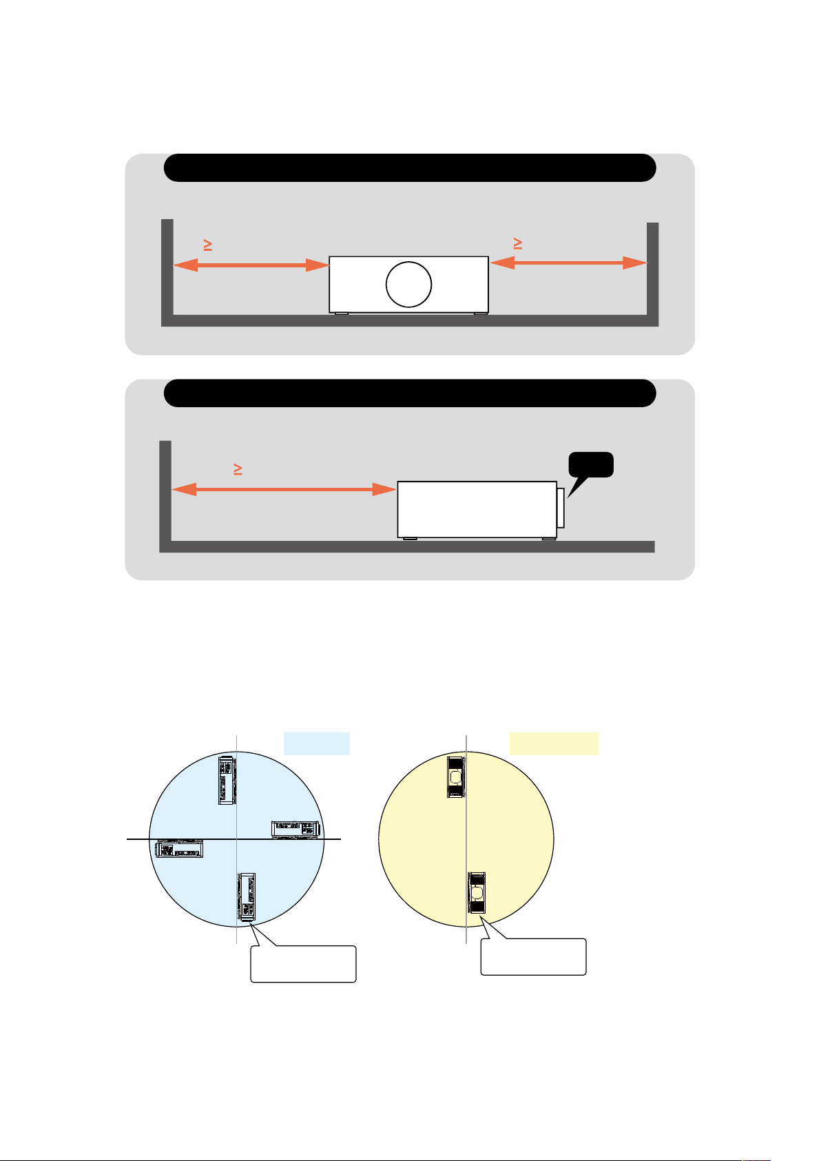
Warning, Notices and Safety Instructions
Distance must
50cm(19.7 inch)
Lens
If there has the obstacles on projector both sides.
Distance must
30cm(11.8 inch)
Distance must
30cm(11.8 inch)
If there has the obstacles on projector both sides.
Positioning Precautions
This projector can be installed 360° range (include portrait). But life of optical parts will be
shorten as following situation:
1.If the projector installed when the lens faces downward.
2.If the projector installed when the IO connect side upward at the portrait situation.

English - 10
Warning, Notices and Safety Instructions
Caution for 3D
Don't let children view the 3D by themselves , please always be accompanied by an adult.
Although more than six years old can view the 3D. But children may not tell you if they are feeling
unwell when viewng 3D content, so always be sure to check with the child.
When viewing 3D content, be sure you are at an appropriate distance from the front of the screen.
Suggest keep least three times the height of the screen away from the screen.
Check that the settings are correct and that the 3D effect is being correctly applied. If the image is
inversed and the left and right eye images are swapped, the 3D effect does not work, which could
cause eye strain or cause you to feel unwell.
3D content not suitable for below situation, it could aggravate their pre-existing conditions.
People with a history of photosensitive epilepsy.
People has heart disease.
Pregnant women.
People with serious illnesses.
People with a history of epileptic seizures.
Suggest stop to view the 3D, if has below situation:
When you feel unwell , tired, sleep deprived, fatigued or inebriated,
The 3D image doubled or not clear.
Enjoying 3D content that rotates, rolls, or shakes, some person may feel they are moving and
trigger a form of “sea sickness”.
Take too long time for viewing 3D content, be sure to take regular breaks to avoid cause eyestrain.
English - 11
Warning, Notices and Safety Instructions
LASER WARNING
this symbol indicates that there is a potential hazard of eye exposure to
laser radiation unless the instructions are closely followed.
CLASS 3R LASER PRODUCT
This Laser Product is designated as Class 3R during all procedures of operation.
LASER LIGHT - AVOID DIRECT EYE EXPOSURE.
Direct or scattered light can be hazardous to eyes and skin.
There is a potential hazard of eye exposure to laser radiation if the included
instructions are not followed.
Caution – use of controls or adjustments or performance of procedures other than those
Laser Parameters
Wavelength
Mode of operation
Pulse width
Pulse repetition rate
Maximum laser energy
Total internal power
Apparent source size
Divergence
450nm - 460nm (Blue)
Pulsed, due to frame rate
0.74ms
240Hz
0.376mJ
>100W
>10mm, at lens stop
>100 mili Radian
English - 12
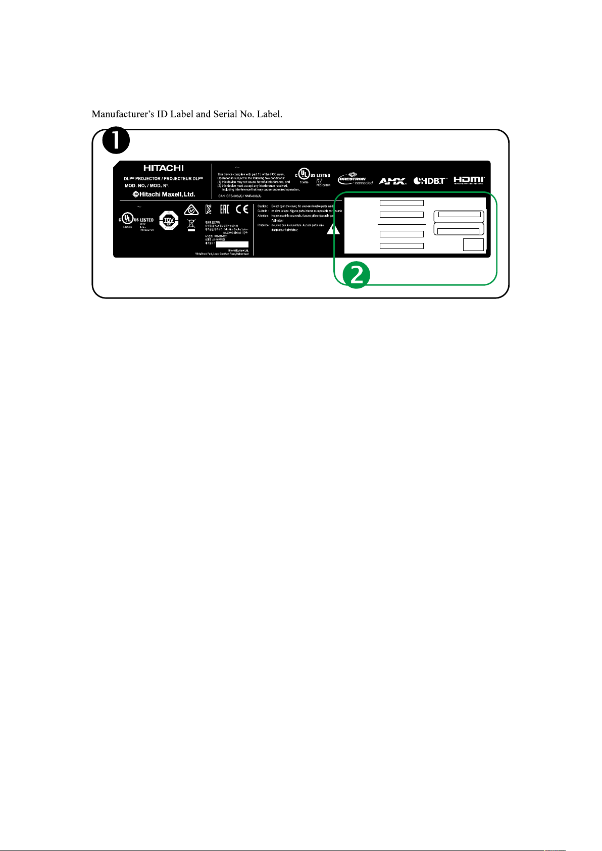
Warning, Notices and Safety Instructions
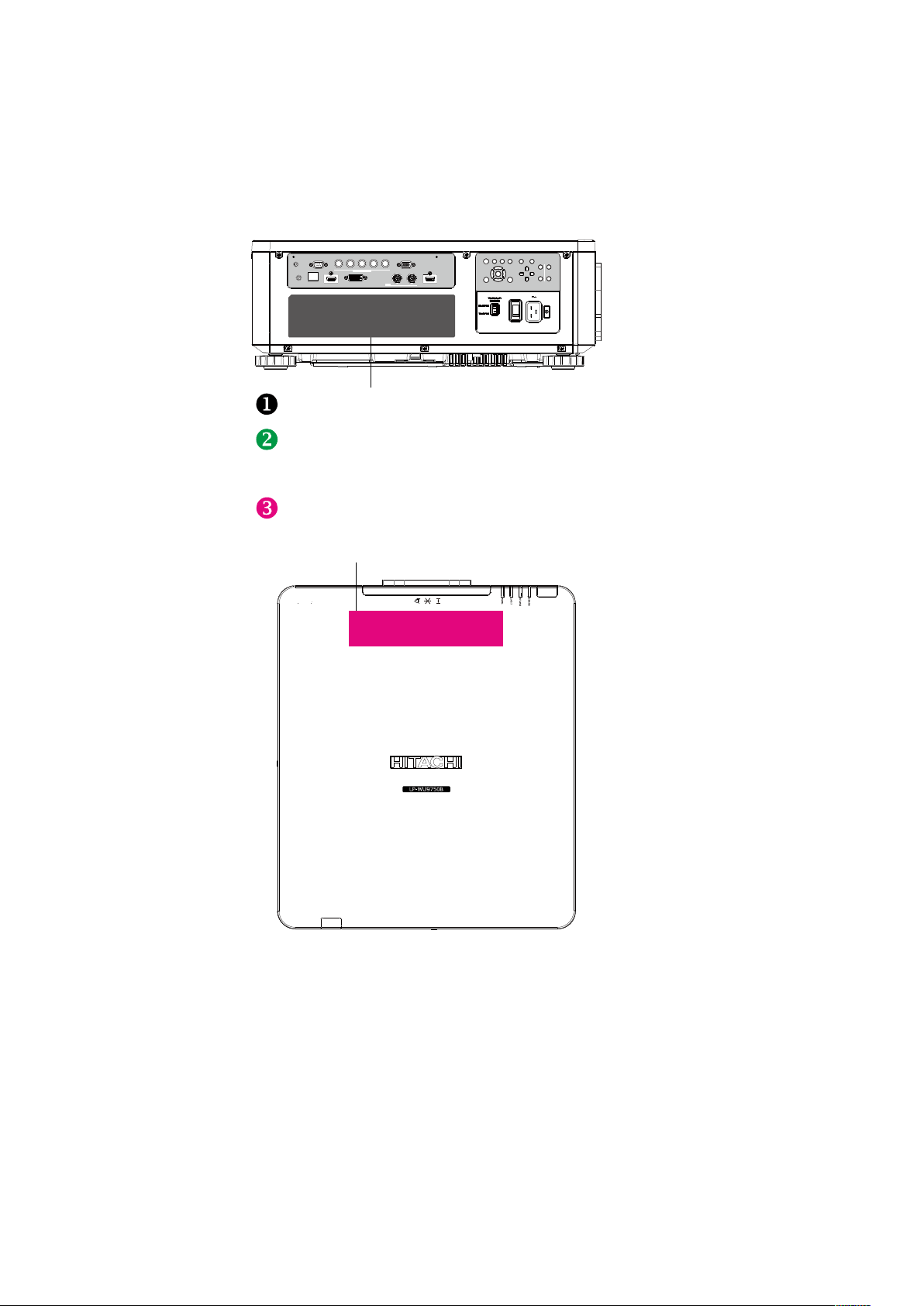
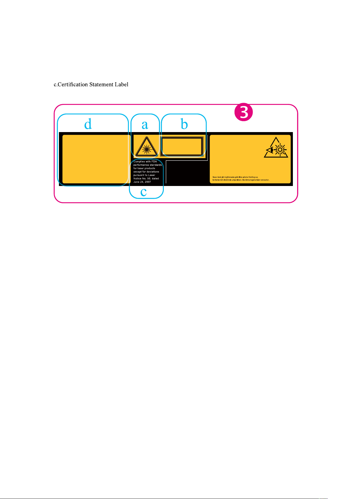
Product labels
Below drawing show the label's location.
English - 13
Warning, Notices and Safety Instructions
English - 14
Warning, Notices and Safety Instructions
a.Hazard Warning Symbol
b.Aperture Label
d.Explanatory Label
English - 15
Warning, Notices and Safety Instructions
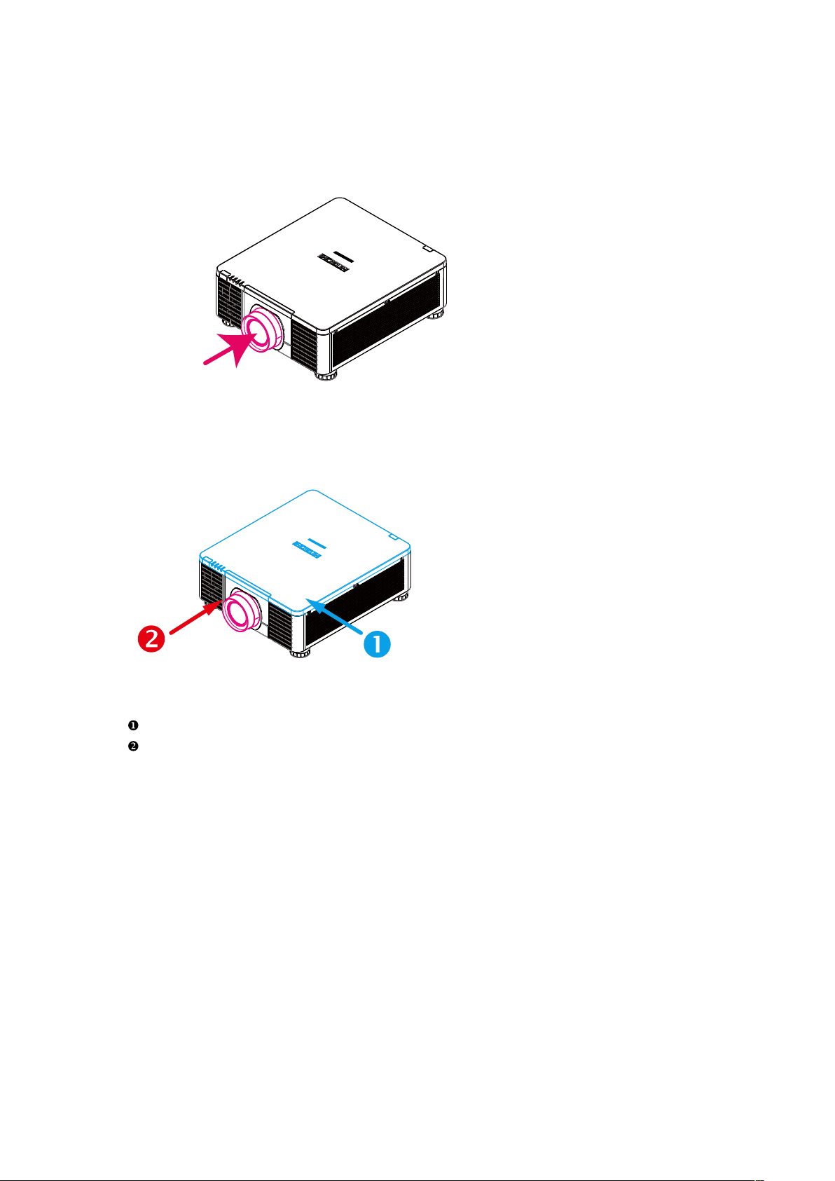
Location of laser aperture
For eye's safety - Don't stare into the lens, the laser aperture.
Laser aperture
Interlock switches
This product is equipped with interlock switches to further protect end user from laser exposure.
Switch will power-off the system when the Top cover is opened.
Switch will power-off the system when the lens is removed or not installed correctly.
English - 16
Warning, Notices and Safety Instructions
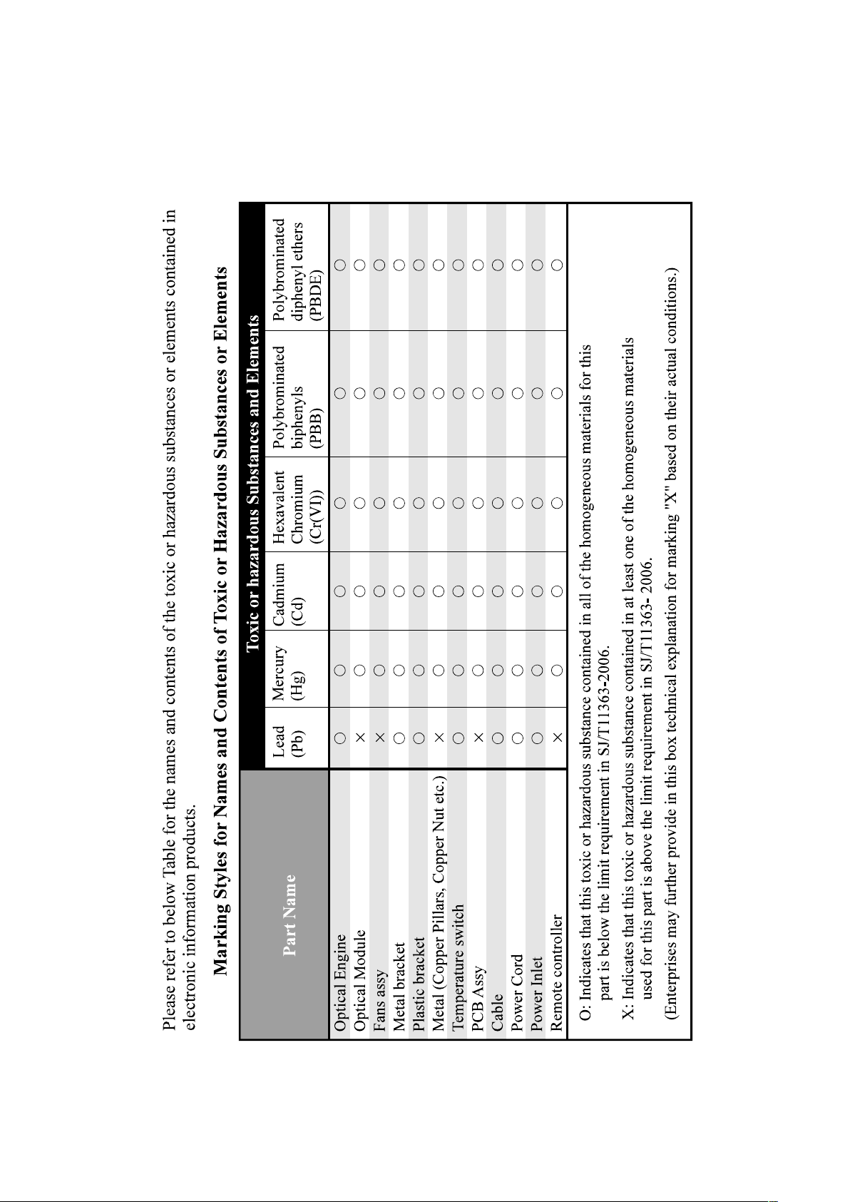
Name and quantity of toxic/hazardous substances/elements contained
in the product
English - 17
Projector parts and functions
Projector parts and functions
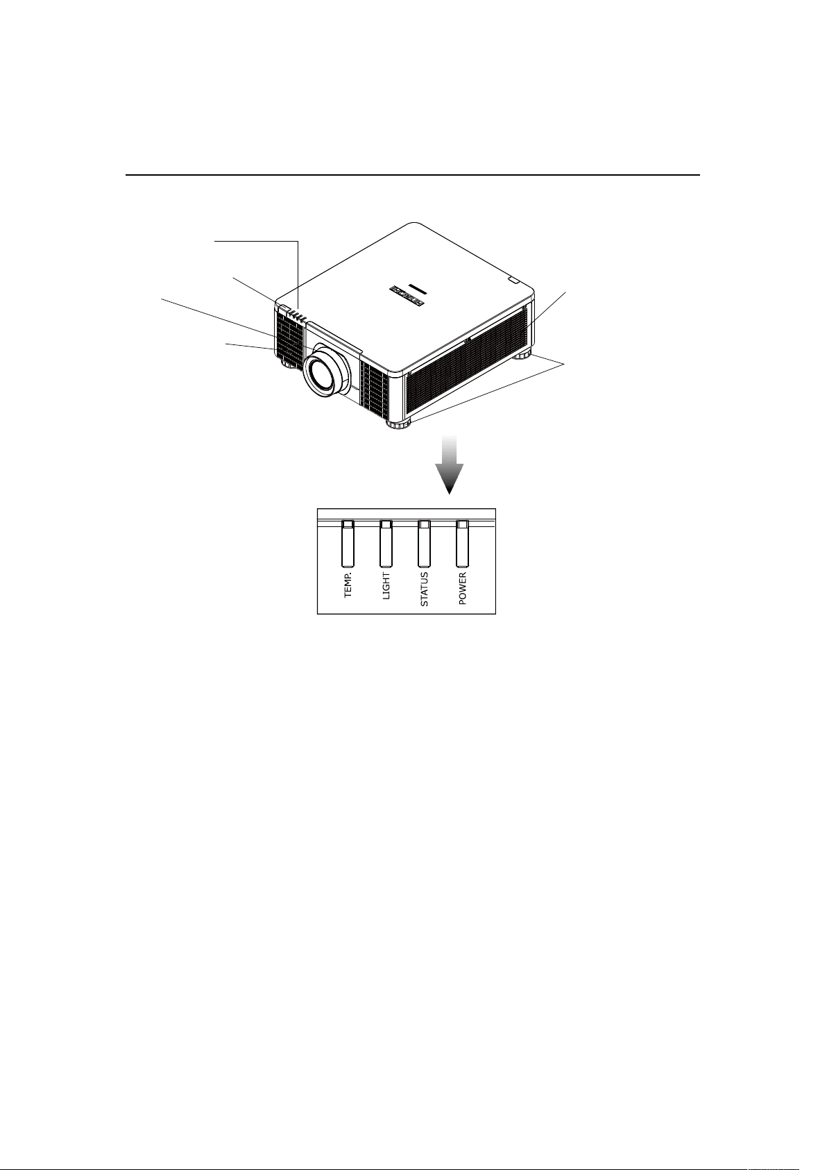
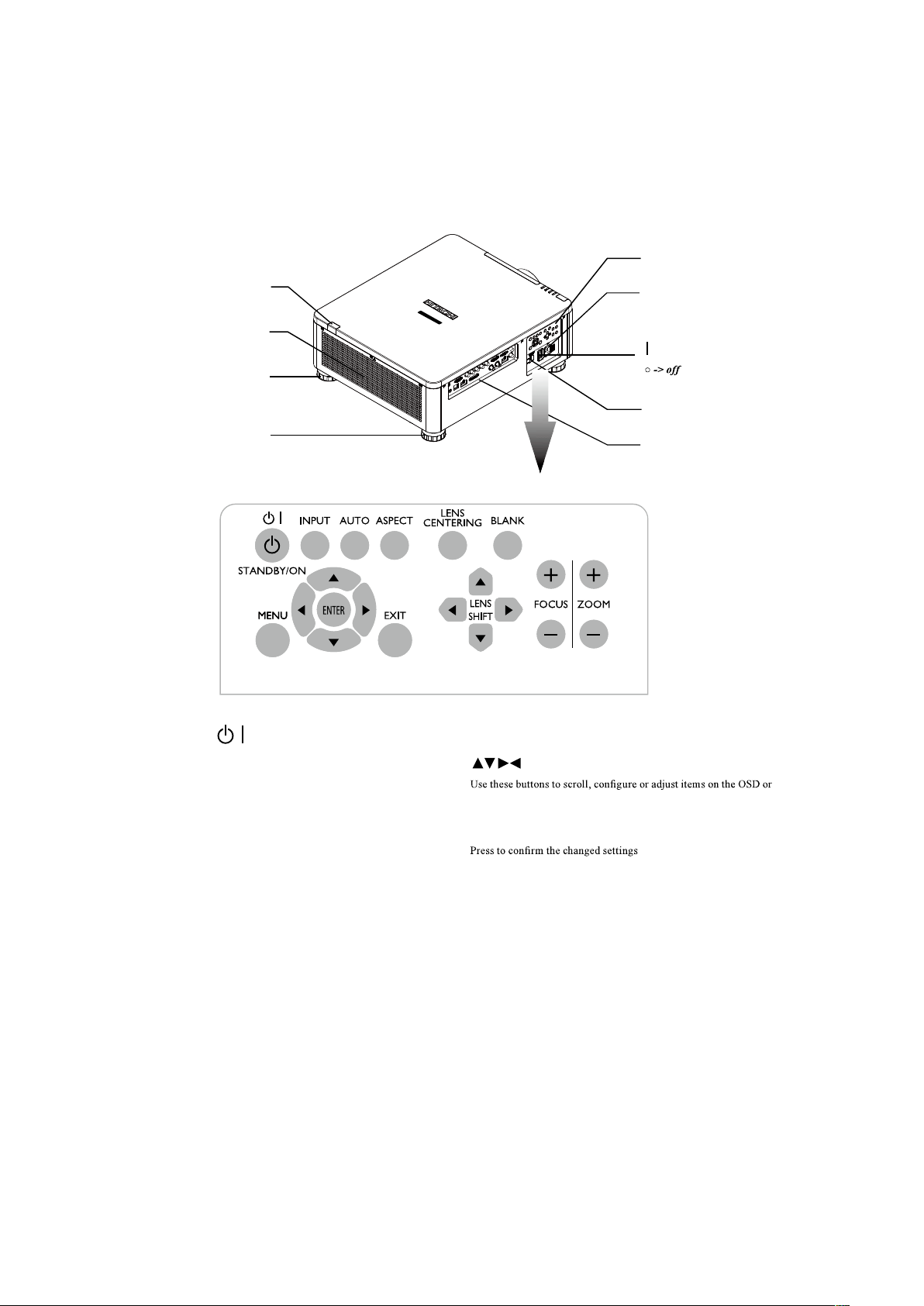
Front view
POWER (LED)
The indicator that shows the projector's power status.
STATUS (LED)
The indicator that shows the projector's standby status.
LIGHT (LED)
The indicator that shows the projector is on or off.
TEMP. (LED)
The indicator that shows the projector's error message.
LED Indicator
Lens
Infrared receiver
Adjustable foot
Adjust the height and angle of the
projector with the adjustable foot
Ventilation inlet
The internal cooling fan draws cool
air from the ventilation inlet into the
projector.
Ventilation slot
The hot air generated
inside the projector is
dispersed through the
ventilation slot. Make
sure the ventilation slot is
free from obstruction.
English - 18
Projector parts and functions
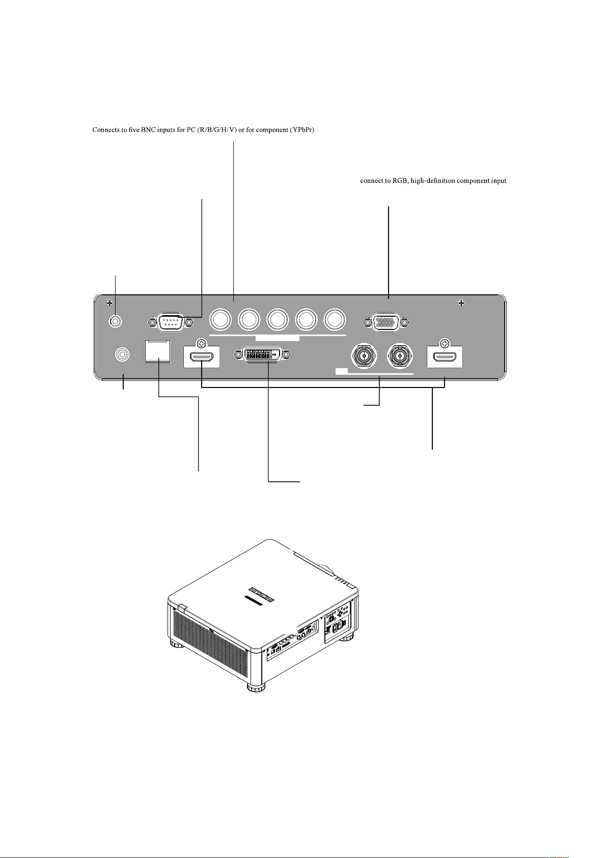
Rear view
Voltage Selector
(Default at 115V)
Adjustable foot
Adjustable foot
Infrared sensor
Power inlet
Projector Keypad
IO Control
Power switch
-> on
Ventilation outlet
STANDBY.
Use this button to start up or shut down the projector .
INPUT
Used to toggle between different input signal source.
AUTO
Auto adjust the signal synchroniztion.
ASPECT
Adust the aspect ratio. Refer to " Page 45 : Aspect "
LENS CENTERTNG
Press this button to center the lens and calibrate the parameter of
lens shift, focusing and zooming.
BLANK
Press this button display the blank image.
MENU
Displays or hides the OSD adjustment screen.
BUTTONS
toggle between different pictures.
ENTER
EXIT
Exit the OSD adjustment screen or return to previous osd level.
LENS SHIFT
Adjust the projected image posion.
FOCUS
Adjust the projected image's focus.
ZOOM
Zoom in or zoom out the projected image.
English - 19
Projector parts and functions
TRIGGER
(3.5-mm, mini phone jack)
Offers 12 (+/- 1.5) V of output for
350mA monitor relay with short
circuit protection.
To keep with cover while not in use.
HDBaseT
HDBaseT is a technology to transmit image,
sound, ethernet or serial control signal via
LAN cable.
LAN
IN OUT
SDI
COMPUTER IN 2
REMOTE
CONTROL HDBaseT HDMI 1 DVI-D HDMI 2
TRIGGER
CONTROL V H
B/Cb/Pb
G/Y R/Cr/Pr COMPUTER IN 1
CONTROL
9-pin D-sub socket. Connects your PC or
automatic home theater /control system.
HDMI 1 & 2
HDCP compatible digital picture input; connects
to sources using HDMI or DVI.
REMOTE
CONTROL
Usable wired-remote-control
with accessory cable. Available
for Niles or Xantech IR repeater
systems.
COMPUTER IN 2
picture source and channel (Hs, Vs) source.
COMPUTER IN 1
Standard 15-pin VGA connection socket to
or PC. The projector will automatically detect the
resolution of the input signal.
SDI IN/OUT
Serial digital interface, use BNC
connects input or output the picture.
IO Control (Input / Output)
DVI-D
Connect to DVI source.
English - 20
Projector parts and functions
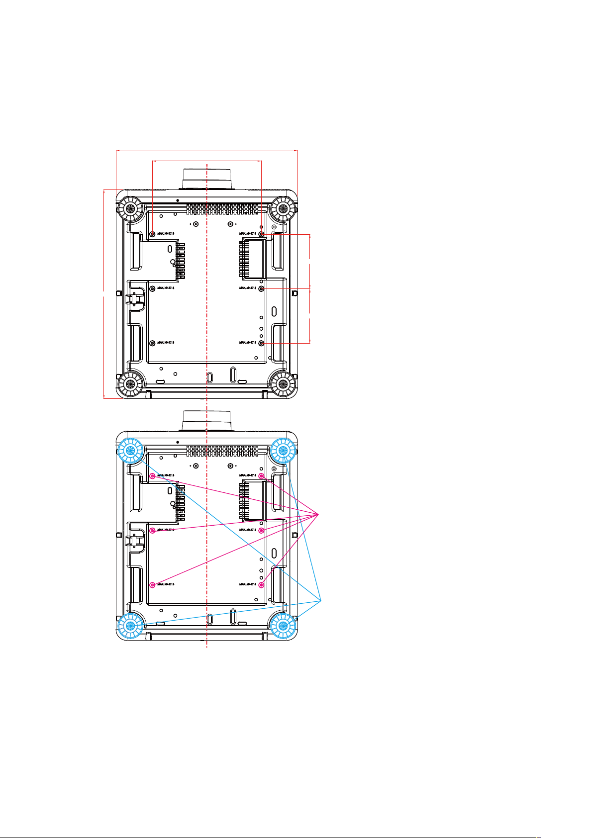
Bottom view
Adjustable foot
Adjust the height and angle of the
projector with the adjustable foot
300,0
150,0
150,0
500,0
576,0
Mounting bracket screw hole
These screw holes are used to mount the
projector to its designated mounting bracket
using 6 M4x16 screws. The dimensions of the
screw holes are shown in the picture below.
English - 21
Projector parts and functions
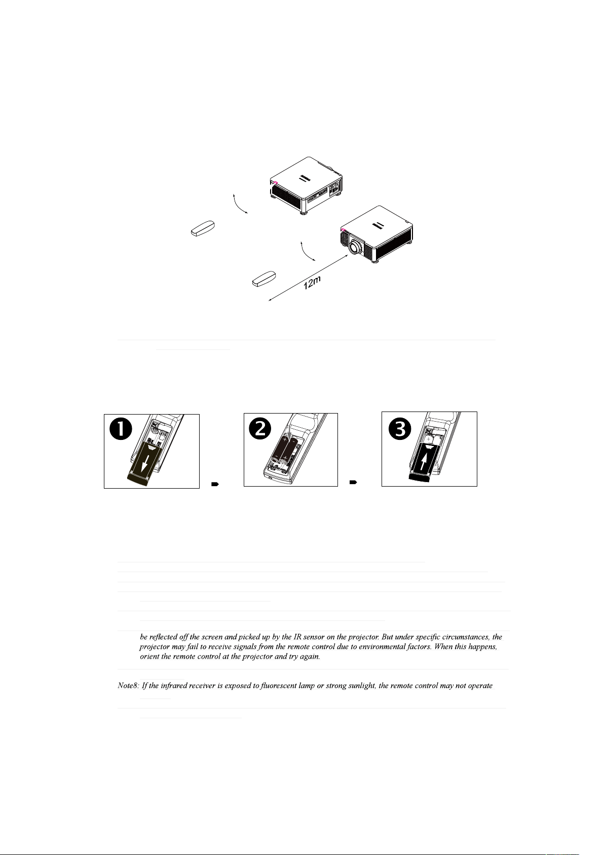
Range of effective remote control signal reception
The diagram below illustrates the range of effective remote control signal reception (Unused new
battery).
40°
40°
Note: Avoid placing the remote control at places of high temperature or humidity as it could cause the remote
control to malfunction.
Installing batteries in the remote control
1. Remove the cover by sliding it in the direction indicated by the arrow.
2. Insert two new AA batteries (observe the polarity).
3. Replace the cover.
Note1: Be sure to insert the batteries in the corresponding orientations to match the polarities.
Note2: Do not mix new batteries with used batteries as it would shorten the life of new batteries or cause leakage.
Note3: Only used AA batteries as instructed; do not attempt to insert different types of batteries into the remote control.
Note4: If the remote is going to be unused for long periods of time, be sure to remove the batteries to prevent leakage,
which could damage the remote control.
Note5: The liquid contents in the batteries is harmful to the skin; do not touch the leakage with your bare hands directly.
When installing fresh batteries, be sure to clean up the leakage thoroughly.
Note6: Under most circumstances, you only need to point the remote control towards the screen and the IR signal would
Note7: If the range of effective remote control signal reception decreases or if the remote control stops working, replace
the batteries.
normally.
Note9: Refer to the regulations enforced by your local government on the disposal of used batteries; improper disposal
could damage the environment.
English - 22
Installation of the Projector
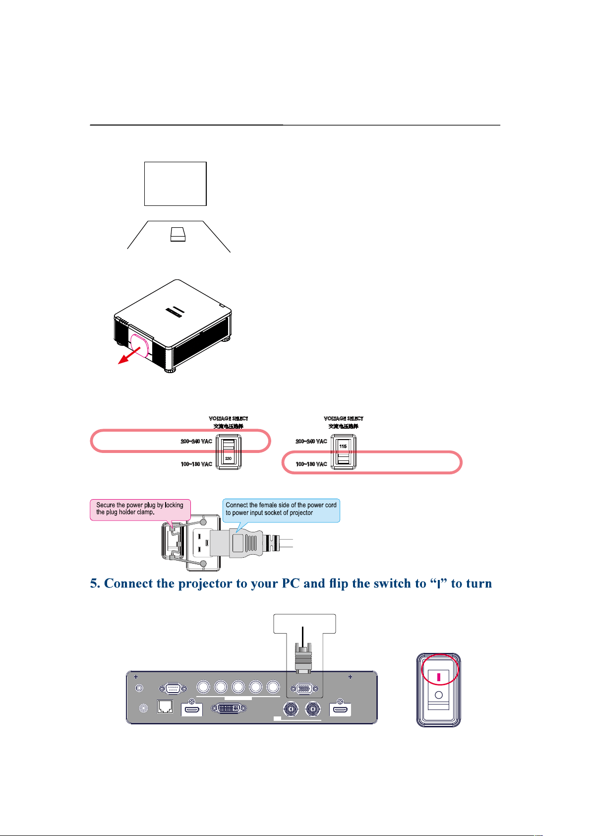
Installation the projector.
Installation the projector.
1. Orient the projector towards the screen
Screen
2. Remove the lens PU foam on the projector
3. Depending on your area, to select the correct input voltage.
Select 200-240V
Select 100-130V
4. Connect the power cord to the projector
on the power.
LAN
IN OUT
SDI
COMPUTER IN 2
REMOTE
CONTROL HDBaseT HDMI 1 DVI-D HDMI 2
TRIGGER
CONTROL V H
B/Cb/Pb
G/Y R/Cr/Pr COMPUTER IN 1
Desk Top or Notebook
English - 23
Installation of the Projector
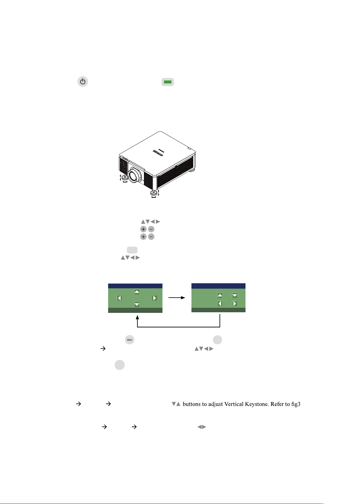
6. Starting the projector up.
Press the button on the projector or the button on the remote control to start up the
projector.
7. Adjusting the projector's angle, Lens Shift, Zoom and Focus
a. Please use the adjustable feet to change the angle of the projector in order to achieve the most
suitable angle for projection on the screen.
b. Adjusting the lens by horizontal and vertical lens shift and adjust Zoom and Focus of lens
Method 1: Use the Keypad of
Lens Shift
Focus
Zoom
Method 2: Press the
button on the remote control to access Lens Control-Lens Shift.
Use the buttons to adjust the horizontal or vertical position of the lens.
Then press ENTER to adjust the Zoom and Focus of the lens.
Lens Control
[Enter] Shift Adjustment
Zoom
Focus
Lens Control
[Enter] Zoom/Focus Adjustment
Shift
Press Lens Shift once to
adjust Lens Shift
Enter
Enter
Press Enter to adjust the
Zoom and Focus
Method 3: Press the button on the remote control or
MENU
Keypad and choose Advanced
Lens Control selected, then use the buttons to adjust the horizontal or
vertical position of the lens. If want to adjust Zoom and Focus.
Press
to adjust it.
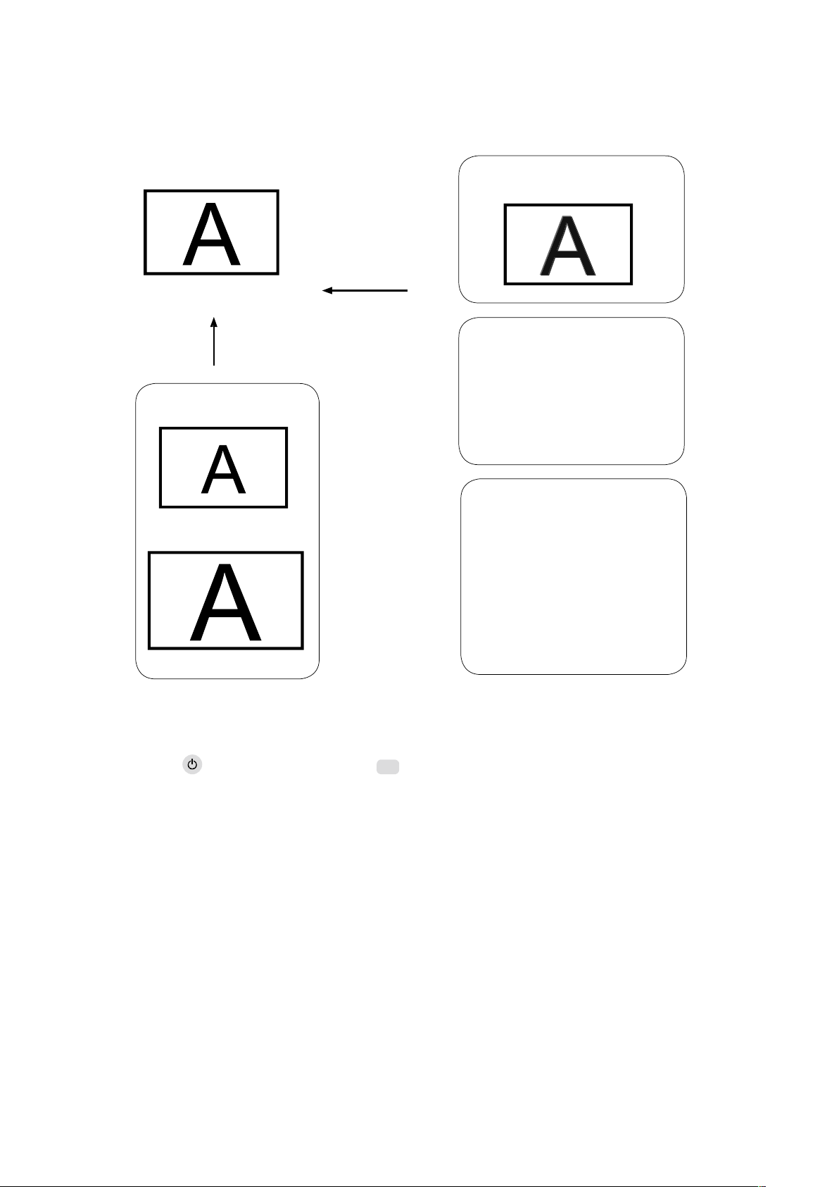
8. Correcting keystoning caused by projection angle
a. To adjust keystoning, press the MENU button on the remote control and choose Advanced
Warping Keystone adjust and use
on next page.
b. To adjust keystoning, press the MENU button on the remote control and choose
Advanced Warping Keystone adjust and use buttons to adjust Horizontal Keystone.
Refer to Fig 4 on next page.
English - 24
Installation of the Projector
The picture after adjust
Adjust
Adjust
Zoom Out
Zoom In
Fig 1
Focus
Fig 3
Vertical Keystone
Fig 4
Horizontal Keystone
9. Turning off the projector
Press the
button on the projector or the
button on the remote control. The message will
appear on the screen. Press the button again while the message appears. When the projector has been
turned off, the cooling fan will remain in operation for approximately 10 seconds.
English - 25
Installation of the Projector
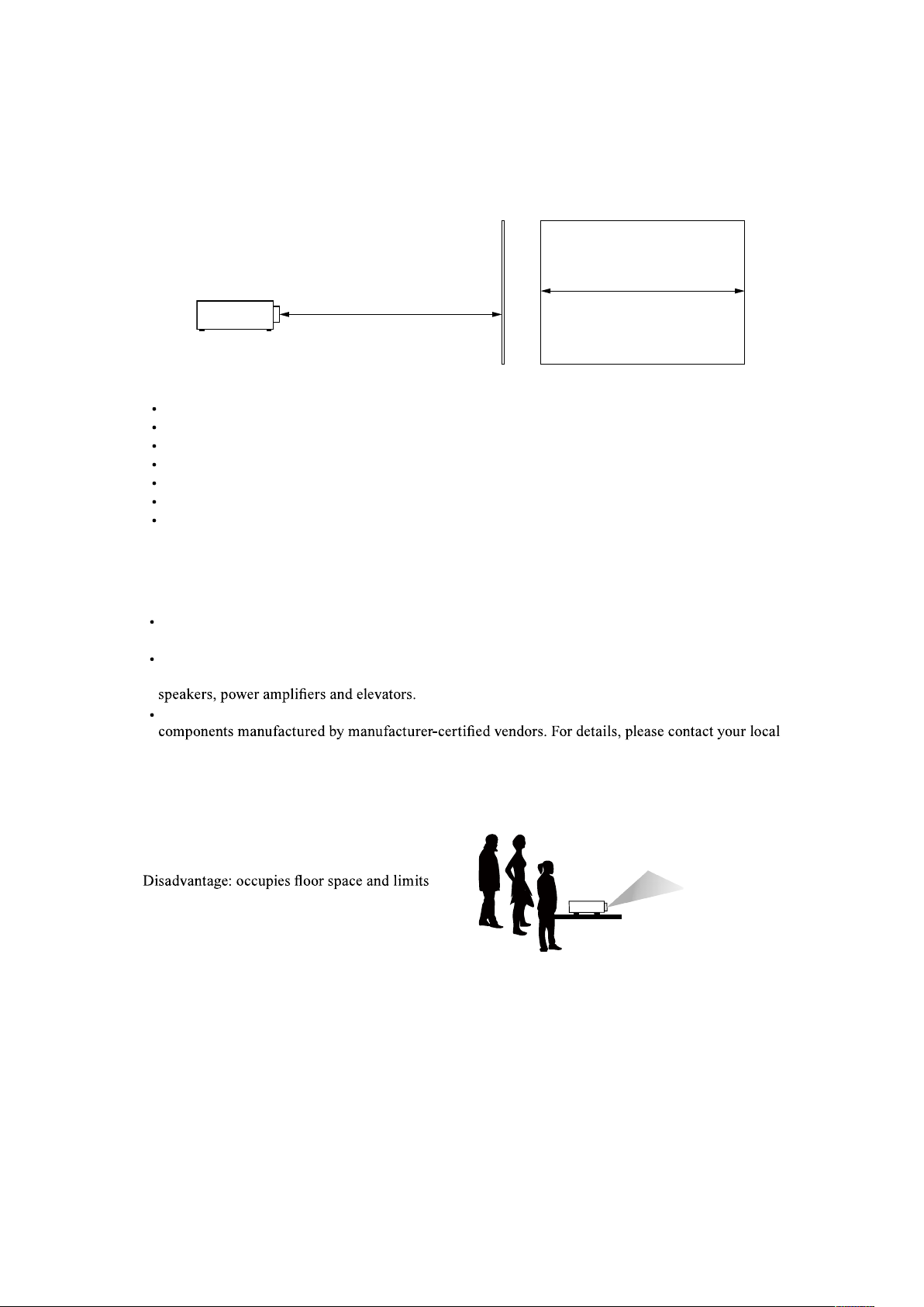
Throw distance
Throw Distance (TD) = Screen Width (W) x Throw Ratio (TR)
Coupled with the available projection lenses, the projector offers the following throw ratios:
FL-920(FL-900) (0.32 : 1 100-350inch)
USL-901 (0.76~0.95 : 1 50-600inch)
SL-902 (1.14~1.72 : 1 50-600inch)
SD-903 (1.61~2.44 : 1 50-600inch)
ML-904 (2.38~3.64 : 1 50-600inch)
LL-905 (3.47~5.63 : 1 50-600inch)
UL-906 (5.53~8.79 : 1 50-600inch)
Note:
Projection lenses are optional accessories.
Please contact your local dealer to acquire
the projection lens that suits your need
most.
Modes of installation
Install the projector in an environment below 40°C (104°F). The projector should be kept clear from
sources of heat and / or ventilation openings of air conditioner.
The projector should be kept away from devices that emit electromagnetic energy, such as motor
and transformer. Common devices that emit electromagnetic energy include slideshow system,
If you choose to install the projector on the ceiling, be sure to use the ceiling installation
dealer.
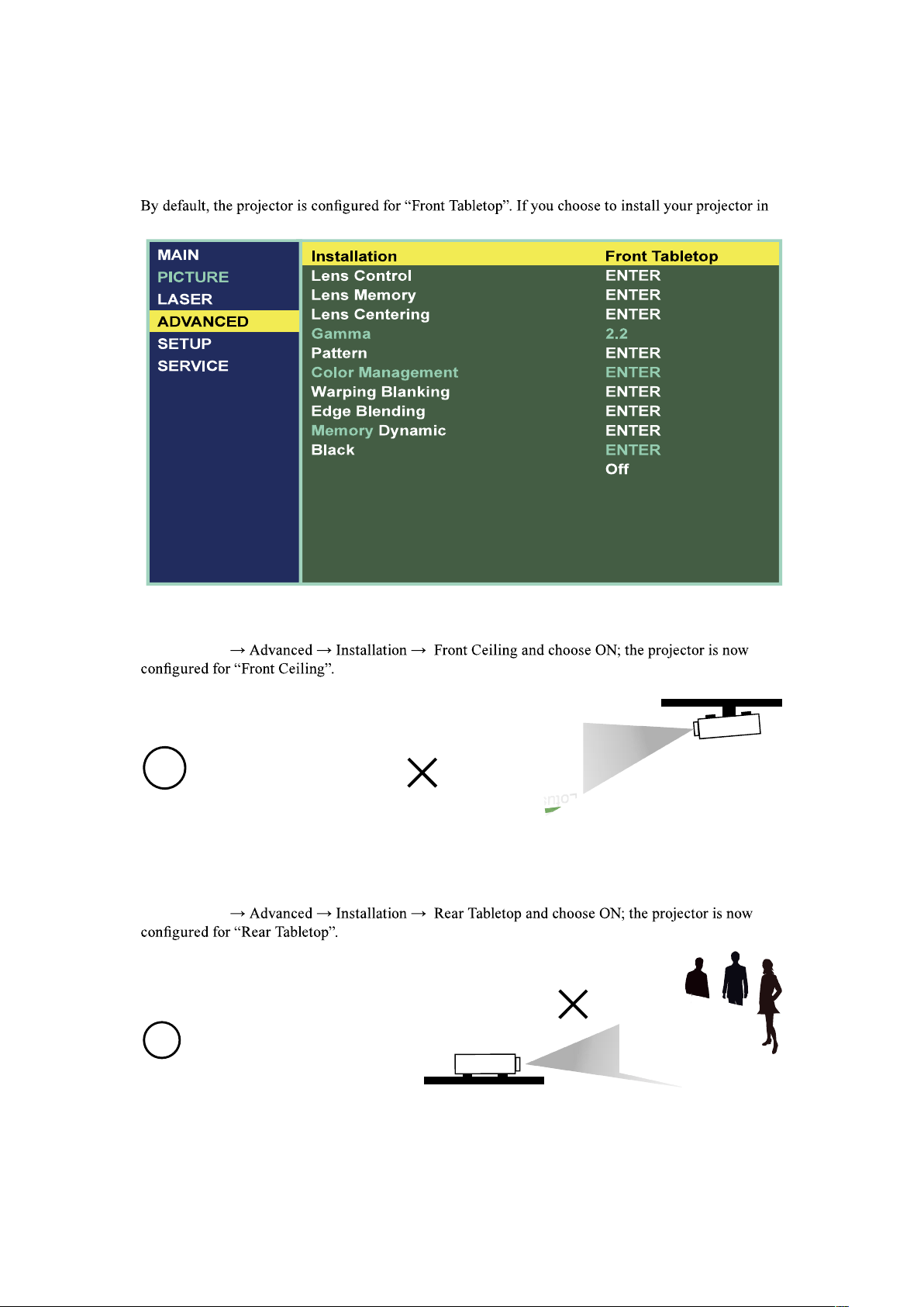
Front Tabletop
Advantages:
easy to install can be easily moved
or adjusted easy to operate.
seating capacity.
English - 26
Installation of the Projector
Front Ceiling
Refer to " Page 31 : Front Ceiling "
draw attention to it.
Eliminates the possibility that
someone would accidentally move
the projector.
Disadvantage:
stricter installation requirements
and conditions; care should be
taken during the installation
to ensure the projector has
been securely mounted.
operation of the projector becomes
inconvenient without the remote
control.
Rear Tabletop
Refer to " Page 31 : Rear Tabletop "
Advantage:
the projector is completely hidden
from plain view
the projector can be easily operated
this setup usually offers better
reduction of ambient noise.
Disadvantage:
requires an additional room for
installation relatively higher costs
for installation.
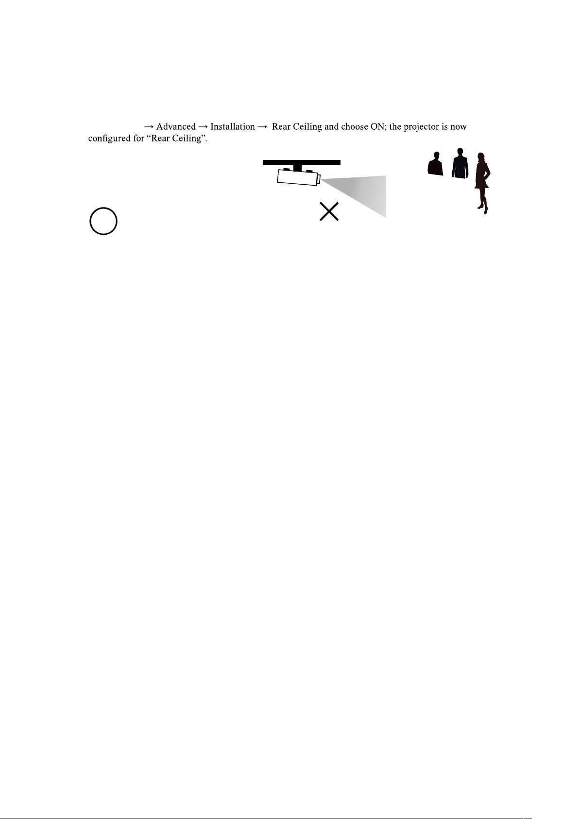
Rear Ceiling
Refer to " Page 32 : Rear ceiling "
Advantage:
the projector is completely hidden
from plain view this setup usually
offers better reduction of ambient
noise.
D
isadvantage:
requires an additional room for
installation. Stricter installation
requirements and conditions;
care should be taken during the
installation to ensure the projector
has been securely mounted.
operation of the projector becomes
inconvenient without the remote
control.
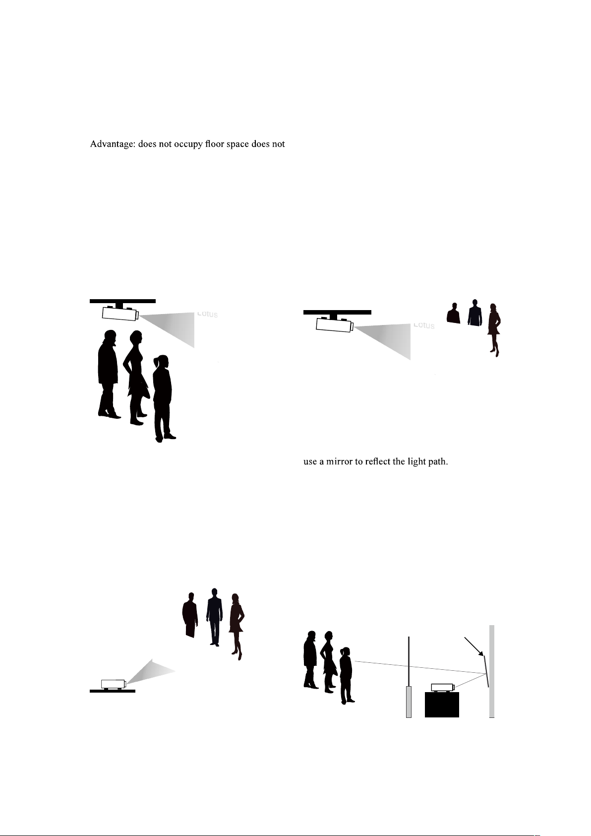
RRear projection - submersive
installation
If you wish to have a rear projection setup with
limited space to the rear of the projector, you can
However, both the projector and the mirror have
to be precisely located. If you are considering
such installation, please contact your dealer for
assistance.
Advantage:
the projector is completely hidden
from plain view this setup usually
offers better reduction of ambient
noise.
Disadvantage:
requires an additional room for
installation relatively higher costs
for installation.
Screen
Mirror
English - 27
Installation of the Projector
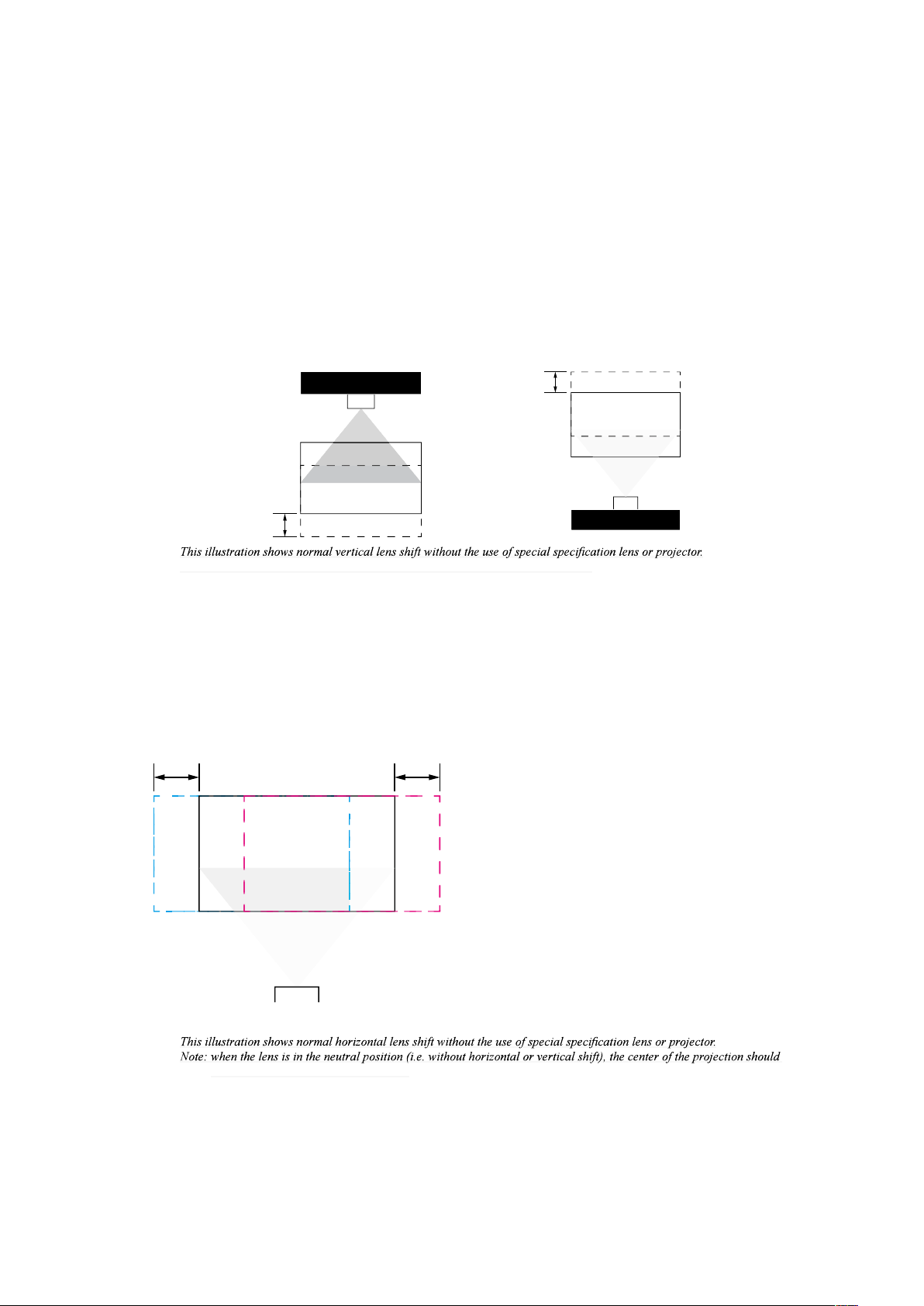
Horizontal and vertical lens shift
In addition to using the adjustable feet to adjust projection angle, you can also use the Lens Shift
function to adjust the projected picture.
Moving the lens vertically
The distance of vertical lens movement is +60% , -22% of half the screen height in both directions.
For instance, if you are using a 2.03m × 1.27m screen, you will be able to move the picture upwards
no more than 63.5cm or downwards no more than 31.8cm.
Note: Please make sure the center of lens is rectangular to the center of the screen.
Moving the lens horizontally
The distance of horizontal lens movement is 20% of half the screen width in both directions. For
instance, if you are using a 2.03m × 1.27m screen, you will be able to move the picture left or right by
no more than 20.3cm.
be aligned with the center of the screen.
English - 28
Installation of the Projector
Connecting the projector to other devices
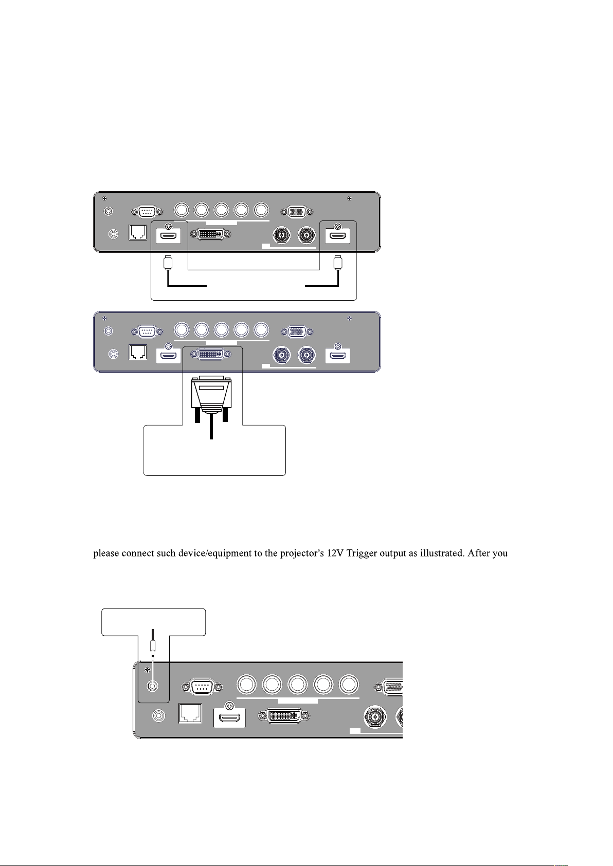
HDMI / DVI connection
Signals from picture source offer the best projection picture quality when sent through HDMI/DVI.
Therefore, try to use input devices with HDMI/DVI output as the source of picture.
12V Trigger connection
If your home theater system includes a projector screen, screen cover or other 12V Trigger equipment,
have done so,
Your screen will lower automatically whenever you turn on your projector for your convenience.
Refer to menu in the CD " Page 57 : Trigger "
LAN
IN OUT
SDI
COMPUTER IN 2
REMOTE
CONTROL HDBaseT HDMI 1 DVI-D
TRIGGER
CONTROL V H
B/Cb/Pb
G/Y R/Cr/Pr
COMPUTER IN 1
Retractable screen or other
12V device
English - 29
Installation of the Projector
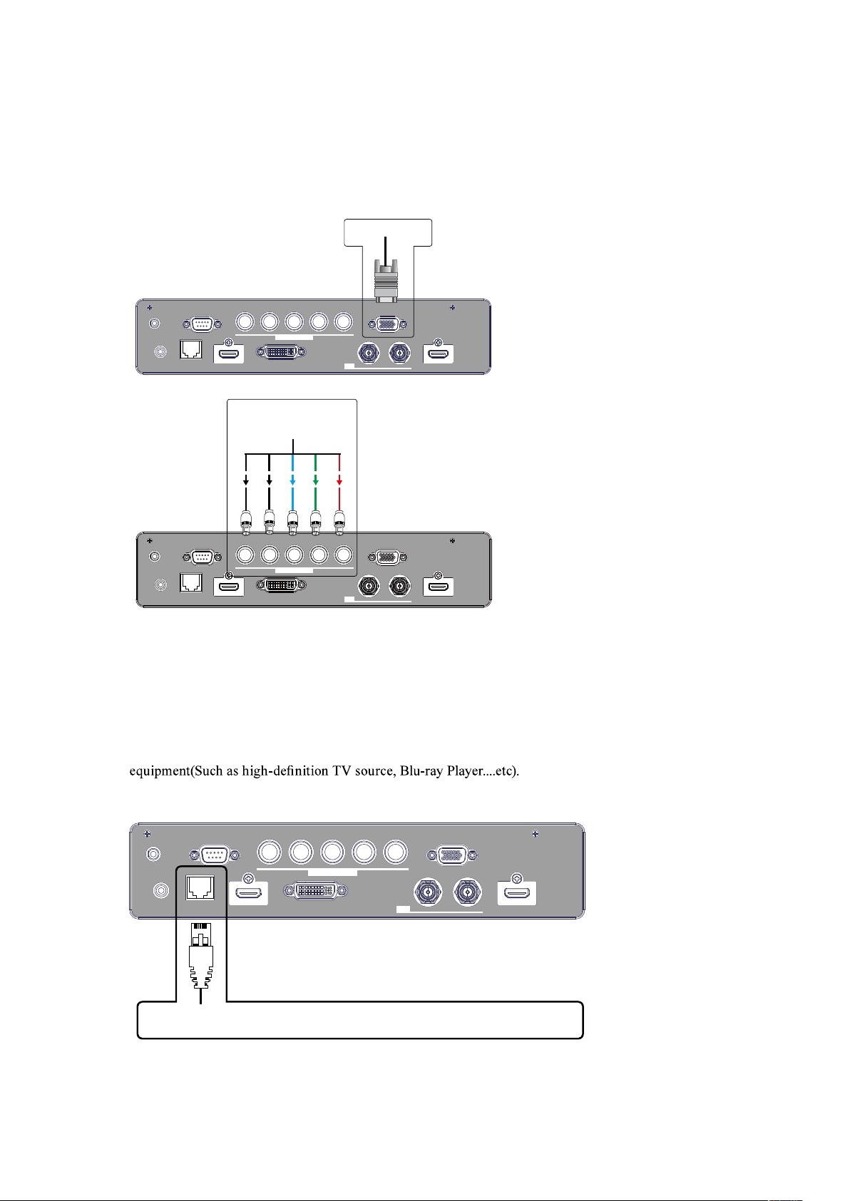
RGB connection
Connect your PC or other devices with RGB output to the RGB input connectors on the projector to be
used as the source of picture input.
LAN
IN OUT
SDI
COMPUTER IN 2
REMOTE
CONTROL HDBaseT HDMI 1 DVI-D HDMI 2
TRIGGER
CONTROL V H
B/Cb/Pb
G/Y R/Cr/Pr COMPUTER IN 1
Desk Top or Notebook
LAN
IN OUT
SDI
COMPUTER IN 2
REMOTE
CONTROL HDBaseT HDMI 1 DVI-D HDMI 2
TRIGGER
CONTROL V H
B/Cb/Pb
G/Y R/Cr/Pr COMPUTER IN 1
G/Y B/Pb R/Pr H V
Desk Top or Notebook
HDBaseT connection
HDBaseT is a technology to transmit image signal using a LAN cable.
Lan Connection - When this connector to be the Lan(RJ-45) function. Connect it to computer or Hub.
Key in the correct IP Address or the computer host name which same as the projector's host name then
you can remote control the projector by internet.
Video Signal - When this connector to be the video signal input. Connect it to HDBaseT output
Use LAN cables of up to 100m long. Exceeding this length, the image will be deteriorated, and even
experience malfunction on LAN transmission.
English - 30
Installation of the Projector
SDI connection
This projector can be connected with other equipment that has SDI connector, but with some
equipment the projector may not work properly.
Use a cable of 5CFB or greater (5CFB, 7CFB, and so on), or Belden 1694A or greater to transmit the
image properly. Use a cable with a length of 100m or less..
Turning on the projector
Refer to the instructions covered in " Page 22 : Installation the projector. "
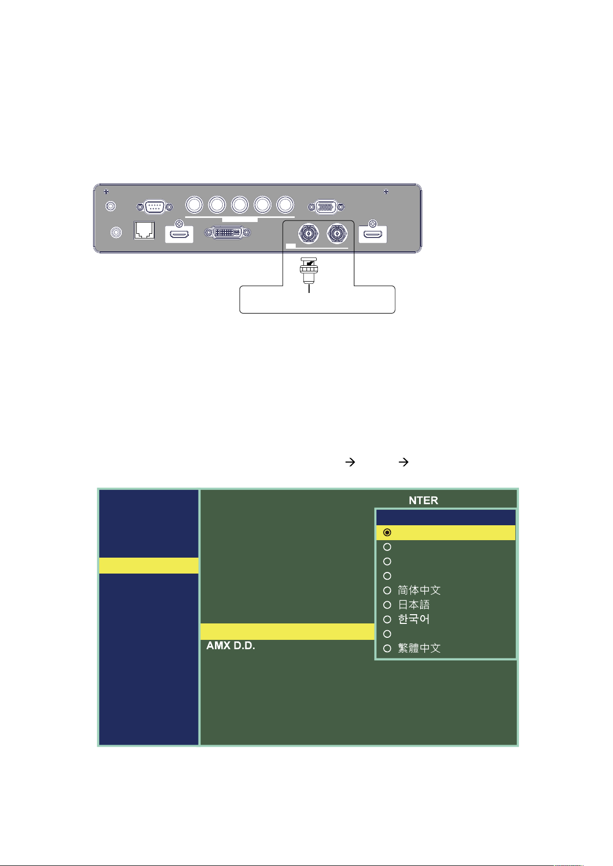
Changing OSD language
By factory default, the OSD menu of the projector is displayed in English. If you wish to
switch to a different language, you can go to MENU SETUP Language and choose
the language you prefer for the OSD.
MAIN
PICTURE
LASER
ADVANCED
SETUP
SERVICE
Network
OSD Settings
Infrared Remote
Remote ID
Startup Logo
Trigger
Auto Search
Auto Power Off
Direct Power On
Language
E
Enter
On
0
On
Screen
Off
Off
OFF
English
Language
English
Français
Español
Deutsch
Português
English - 31
Installation of the Projector
Adjusting screen orientation
other setups, be sure to adjust the screen orientation to achieve the correct projection mode.
Front Ceiling
Press
MENU
Correct Picture
Lotus
Rear Tabletop
Press
MENU
Lotus
Correct Picture
English - 32
Installation of the Projector
Rear ceiling
Press
MENU
Lotus
Correct Picture
Adjusting the projector lens
Projector lens adjustment includes focus, zoom, horizontal/vertical picture shift. Please refer to "
Page 23 : 7. Adjusting the projector's angle, Lens Shift, Zoom and Focus " and " Page 23 : 8.
Correcting keystoning caused by projection angle " for detailed instructions.
English - 33
REMOTE CONTROL
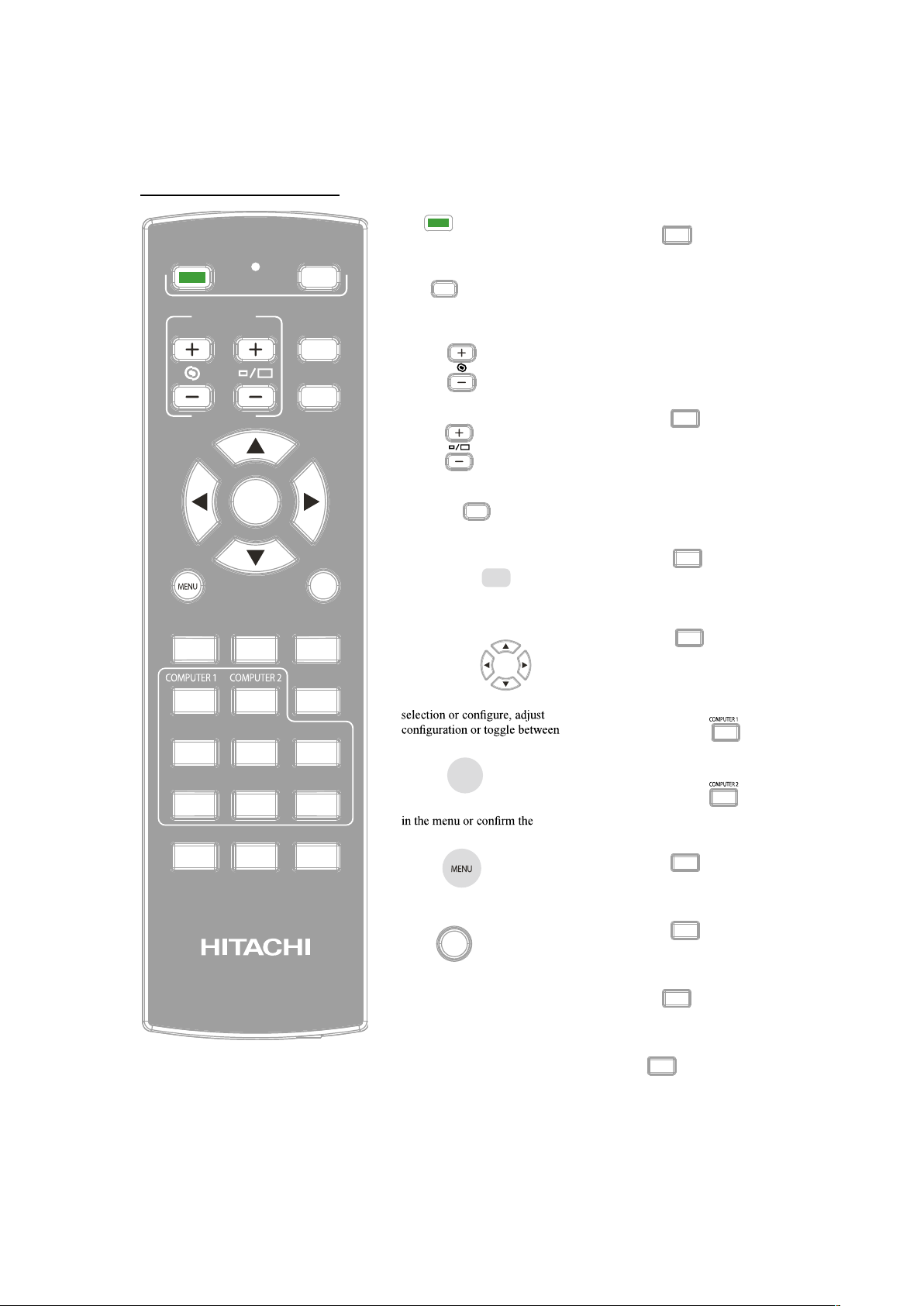
Remote control
1. ON
This button is used to turn on
the projector.
2. OFF
This button is used to turn off
the projector.
3. FOCUS
Adjust the image focus.
4. ZOOM
Adjust the image zoom.
5. PATTERN
Repeat press this button to
select different test pattern.
6. LENS SHIFT
Repeat press this button to
adjust the lens focus, zoom and
control lens to center.
7. ARROR KEY
Use these buttons to make your
picture displays.
8. ENTER
Use this button to select items
settings you have changed.
9. MENU
Press this button to show or
hide the OSD Menu.
10. EXIT
Press this button to exit , hide
the OSD Menu or return to
previous OSD Menu level.
11. AUTO
This button is used to Resync
the picture; when the picture
signal becomes unstable or
picture quality deteriorates
simply press this button and
the projector will automatically
adjust the screen dimension,
phase, timing and so forth.(The
adjustments also apply to PinP
input).
12. BLANK
If the projector projected on
the whiteboard. and you need
to write something on the
whiteboard. You can press this
button let the projector not
display anything and protect
your eyes.
13. STATUS
Display the projector's
information. Same as the OSD
-> Service.
14. ASPECT
You can scroll through different
aspect ratios by pressing this
button repeatedly.
Refer to " Page 45 : Aspect "
15. COMPUTER 1
Hotkeys to select the input
source - Computer 1.
16. COMPUTER 2
Hotkeys to select the input
source - Computer 2.
17. HDMI 1
Hotkeys to select the input
source - HDMI 1.
18. HDMI 2
Hotkeys to select the input
source - HDMI 2.
19. DVI-D
Hotkeys to select the input
source - HDMI 2.
20. SDI
Hotkeys to select the input
source - SDI.
English - 34
REMOTE CONTROL
21. HDBaseT
Hotkeys to select the input source - HDBaseT.
22. FREEZE
Press this button to freeze the projected image. But
Sound still keep going. Only effect image.
23. NUMBER KEY (0-9)
Only availabel for ID Set when these button to be the
number keys.
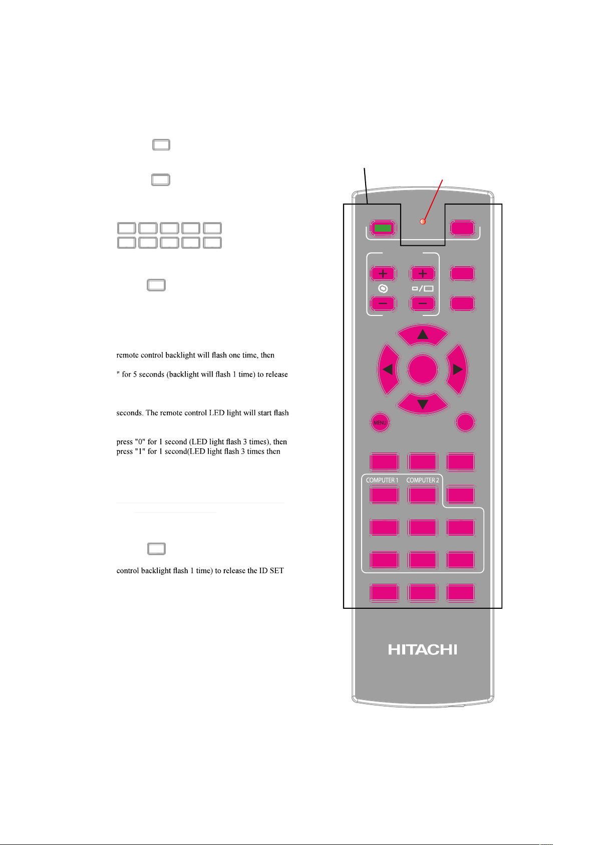
24. ID SET
This function is for set the projector and Remote
control's ID. The projetor can set ID 01-99. After
setup different ID, the remote control will only can
control projector 1 by 1. Can't control other projector.
Press "ID SET + MENU" together for 5 seconds, the
prepared the ID Set mode. Press "ID SET + MENU
ID Set mode.
After prepared the ID Set mode. press ID SET for 3
and remote cotrol backlight lights . Mean you can
press number 0-9 to set the projector's ID. Example 1,
backlight off). success to set the projector ID 01.
Example 2, press "1" for 1 second, then press "9" for
1 second. Success to set the projector ID 19.
Note: This feature is disabled if the device is setting
00 to be the initial value.
25. CLEAR
Press "ID SET + CLEAR " for 5 seconds(Remote
setting.
LED light
Remote control
backlight

English - 35
OSD Menu description
OSD Menu Tree
1st layer 2nd layer 3rd layer 4th layer Selections
MAIN
Input
HDMI1 / HDMI2
COMPUTER IN 1 / COMPUTER IN 2
HDBaseT / SDI / DVI-D
PinP On / Off
PinP Selection
HDMI1 / HDMI2
COMPUTER IN 1 / COMPUTER IN 2
HDBaseT / SDI / DVI-D
PinP Position
Top Left / Top Right
Bottom Left / Bottom Right
PbyP
Color Space
Auto
REC709 / REC601
RGB PC / RGB Video
3D
3D Format
Off / Auto
Side by Side (Half) / Top and Bottom
Frame Sequential
Eye Swap Normal / Reverse
DLP Link On / Off
Magnify & Shift
Magnify 0 ~ 100
Horz Shift -480 ~ 480 (Dynamic)
Vert Shift -300 ~ 300 (Dynamic)
RESET (Execute)
No Signal
Logo / Black
Blue / White
1st layer 2nd layer 3rd layer 4th layer Selections
Picture
Picture Mode
High Bright / Presentation
Video
Brightness 0 ~ 200
Contrast 0 ~ 200
Color 0 ~ 200
Tint 0 ~ 200
Sharpness 0 ~ 20
Noise Reduction 0 ~ 3
Color Temperature
5400K / 6500K
7500K / 9300K
Native
White Balance
Red Offset 0 ~ 200
Green Offset 0 ~ 200
Blue Offset 0 ~ 200
Red Gain 0 ~ 200
Green Gain 0 ~ 200
Blue Gain 0 ~ 200
Aspect
4:3 / 16:10
16:9 / Normal
Native
Over Scan Off / Crop / Zoom
Position and Phase
V Position 0 ~ 200 (Dynamic)
H Position 0 ~ 200 (Dynamic)
H Phase 0 ~ 200
H Size 0 ~ 200 (Dynamic)
Auto Adjust (Execute)
1st layer 2nd layer 3rd layer 4th layer Selections
Laser
Power Mode ECO / Normal / Custom
Power Level 20% ~ 100%
High Altitude Normal / High 1 / High 2 / Auto

English - 36
OSD Menu description
1st layer 2nd layer 3rd layer 4th layer Selections
Advanced
Installation
Front Tabletop / Front Ceiling
Rear Tabletop / Rear Ceiling
Lens Control
Zoom/Focus
Shift
Lens Memory
Load Memory
Memory 1 / Memory 2
Memory 3 / Memory 4
Memory 5
Save Memory
Memory 1 / Memory 2
Memory 3 / Memory 4
Memory 5
Clear Memory
Memory 1 / Memory 2
Memory 3 / Memory 4
Memory 5
Lens Centering (Execute)
Gamma
1.0 / 1.8 / 2.0 / 2.2 / 2.35 /
2.5 / DICOM SIM.
Pattern
Selecting by cursor
button in OSD menu.
Escaping by EXIT
button.
White / Black / Red
Green / Blue / Checkerboard
CrossHatch / V Burst
H Burst / ColorBar
Color Management
Red / Green / Blue
Cyan / Magenta
Yellow
Hue 0 ~ 200
Saturation 0 ~ 200
Gain 0 ~ 200
White
Red Gain 0 ~ 200
Green Gain 0 ~ 200
Blue Gain 0 ~ 200
Warping
Keystone
Horizontal -600 ~ +600
Vertical -400 ~ +400
Rotation -100 ~ 100
Pincushion / Barrel
Horizontal -150 ~ 300
Vertical -150 ~ 300
Top Left Corner
192<X<-192
120<Y<-120
Top Right Corner
192<X<-192
120<Y<-120
Bottom Left Corner
192<X<-192
120<Y<-120
Bottom Right Corner
192<X<-192
120<Y<-120
Reset (Execute)
Blanking
Top 0 ~ 360
Bottom 0 ~ 360
Left 0 ~ 534
Right 0 ~ 534
Reset (Execute)
Edge Blending
Status On / Off
Blending Region
Top / Bottom 0 / 100 ~ 500
Left / Right 0 / 100 ~ 800
Blending Level
Top / Bottom
Left / Right
0 ~ 32
All / Red
Green / Blue
0 ~ 255
Reset (Execute)
Adjust Lines On / Off
Memory
Load Memory
Preset A / Preset B / Preset C
Preset D / Default
Save Settings
Preset A / Preset B
Preset C / Preset D
Clear Settings
Preset A / Preset B
Preset C / Preset D
Dynamic Black On / Off
English - 37
OSD Menu description
1st layer 2nd layer 3rd layer 4th layer Selections
Setup
Network
Network Mode Projector Control / Service
Standby Power On / Off
DHCP On / Off
IP Address xxx.xxx.xxx.xxx
Subnet Mask xxx.xxx.xxx.xxx
Gateway xxx.xxx.xxx.xxx
DNS xxx.xxx.xxx.xxx
MAC Address xxx.xxx.xxx.xxx
OSD Settings
Menu Position
Top Left / Top Right
Bottom Left / Bottom Right
Center
Time Out
Always On / 10 Seconds
30 Seconds / 60 Seconds
Message Box On / Off
Infrared Remote On / Off
Remote ID 0 ~ 99
Startup Logo On / Off
Trigger
Screen / 4:3 / 16:10
16:9
Auto Search On / Off
Auto Power Off On / Off
Direct Power On On / Off
Language
English / French / Spanish
Japanese / Korean
Portuguese / Traditional Chinese
AMX D.D. On / Off
1st layer 2nd layer 3rd layer 4th layer Selections
Service
Model Name
Serial Number
Software Version 1
Software Version 2
Active Source
Signal Format Timing
H Freq
V Freq
Pixel Clock
Laser Hours
Thermal Status Intake Temp.
DMD Temp.
Laser Temp.
Lens Information
1: USL-901
2: SL-902
3: SD-903
4: SD-903W
5: ML-904
6: LL-905
7: UL-906
8: FL-920
0: Unknown
Factory Reset (Execute)
English - 38
OSD Menu description
OSD Description
1. Press the MENU button on the remote control or on the side of the projector to bring up the OSD Menu.
2. You will see six functional menus (Main, Picture, Laser, Advanced, Setup and Service). Press or to select the
desired sub menu.
3. Press or to select the desired sub menu.
4. Your current selection in each of the sub menu will be displayed in black text and highlighted in orange. Press
ENTER ENTER to go to another sub menu.
5. Press MENU to return to the previous menu.
6. From the main menu, press MENU to close the OSD Menu.
7. Some items do not work at the condition of Source, Input signal and Menu setting.
8. Picture may be incorrect when the parameter value is exceeded.
MAIN
MAIN
PICTURE
LASER
ADVANCED
SETUP
SERVICE
Input
PinP
PinP Selection
PinP Position
Color Space
3D
& Shift
No Signal
DVI-D
Off
HDMI 2
Top
Right
Auto
E
E
Logo
Input
This function is same as the hotkey which on Remote controller. You can use remote controller or this
function to select the correct input source.
HDMI1/HDMI2
HDMI input from PC or media device.
Computer In 1
Analog RGB from PC.
Computer in 2 / 5BNC
Analog interface from media device.
HDBaseT
Uncompressed digital video from RJ45.
SDI
Uncompressed digital video from a serial connection (coaxial).
DVI-D
DVI input from PC.
English - 39
OSD Menu description
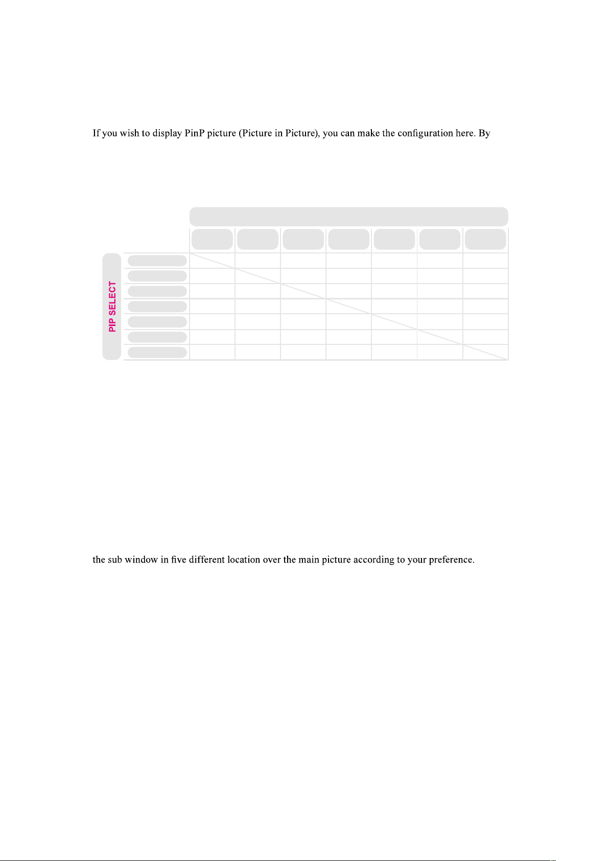
PinP
choosing "ON", you will see two windows on the projected picture; the larger one is the primary
picture and the smaller one is the sub picture. By choosing "OFF", the PinP function will be disabled
and you will only see a single picture window.
*please refer to the following main and PinP source matrix for a valid main and PinP source selection
when PinP is ON.*
PinP/Main Source
Availability
HDMI 1
HDMI 1
COMPUTER IN 2
COMPUTER IN 1
HDMI 2
DVI-D
HDBaseT
SDI
HDMI 2 DVI-D HDBaseT SDI
COMPUTER
IN 2
COMPUTER
IN 1
MAIN SELECT
V
V
V
V
V
V
V V
V
V
V
V
V
V
V
V
V
V
V
V
V
V
V
V
V -> Source available
Empty -> Not available
PinP Selection
Use this function to select the sub picture's input
source. Refer to " Page 38 : Input " for detail
information.
Sub
(PinP)
Main
PinP Position
You can choose to display
PbyP
Bottom
Right
Bottom
Left
Top
Right
Top
Left
English - 40
OSD Menu description
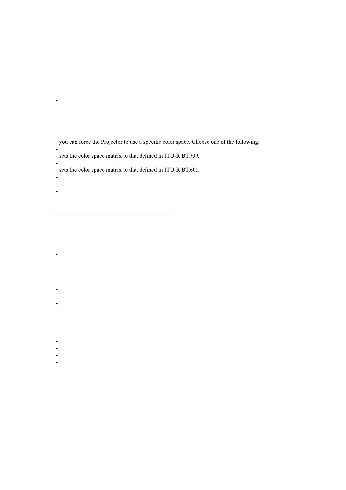
Color Space
Select Color Space from the Advanced menu to choose the color space of the source signal for HDMI,
COMPUTER IN, and component connections.
The default setting, Auto, functions as follows:
Auto
The Auto setting determines the correct color space to be used automatically. For HDMI input,
this determination is based on the AVI infoframe conveying in the input signal. For other input
sources, this determination is based on the timing format of the input signal, for PC/IT formats,
RGB color space will be used, for CE/Video formats, REC601 or REC709 will be used. If the auto
setting dose not determine a correct color space matching the input source signal for some reason,
REC709
REC601
RGB PC
uses RGB color space and sets black at 0,0,0 RGB and white at 255,255,255 RGB.
RGB Video
uses RGB color space and sets black at 16,16,16 RGB and white at 235,235,235.
Note: When SDI input is selected, this function is not available.
3D
For setting the 3D Video each value.
3D Format
Default is "Auto". When 3D image is not display. Mean the input signal does not contain 3D
detection signal or it can't be detected by the projector. This time, you need to select the correct 3D
format manually. There has Off / Auto / Side by Side (Half) / Top and Bottom / Frame Sequntial
can choice.
Eye Swap
Choice "Normal" or "Reverse" to display the correct picture.
DLP Link
This projetor only support DLP Link glassers. If your 3D Glasses is not DLP Link format, set this
function "Off".
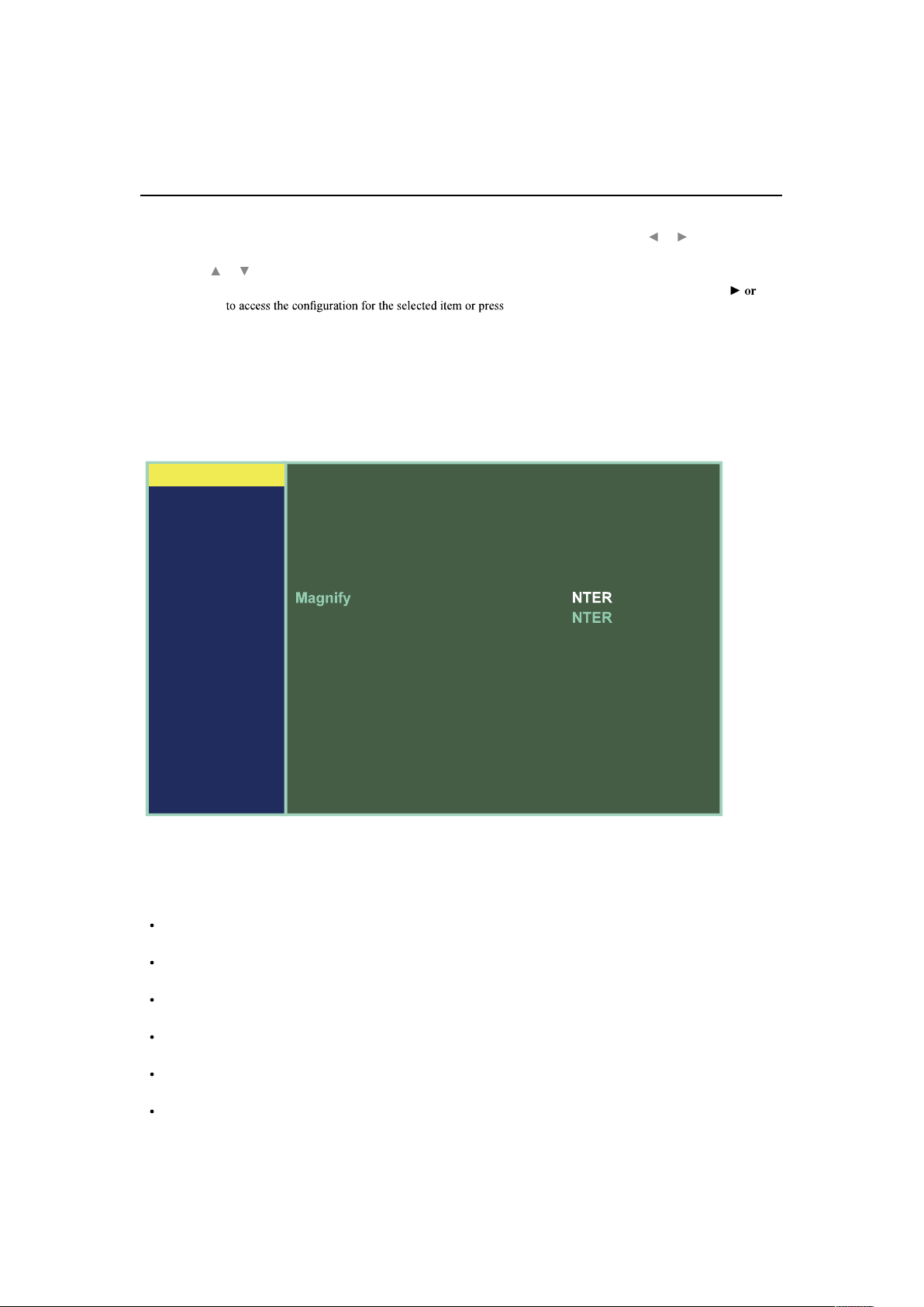
Magnify & Shift
Magnify : Zoom in the projected image.
Horz Shift : Horizontal direction to shift the projected image.
Vert Shift : Vertical direction to shift the projected image.
Reset : Clear all settings of Magnify & Shift.
No Signal
Use this function to specify the content or color to be displayed on the blank screen when no input
signal is available. You can choose from Logo, Blue, Black, White. The default value is Logo.
English - 41
OSD Menu description
PICTURE
MAIN
PICTURE
LASER
ADVANCED
SETUP
SERVICE
Picture Mode
Brightness
Contrast
Color
Tint
Sharpness
Noise Reduction
Color Temperature
White Balance
Aspect
Over Scan
Position and Phase
Auto image
Video
100
100
100
100
10
0
5400K
E
Normal
Off
E
Execute
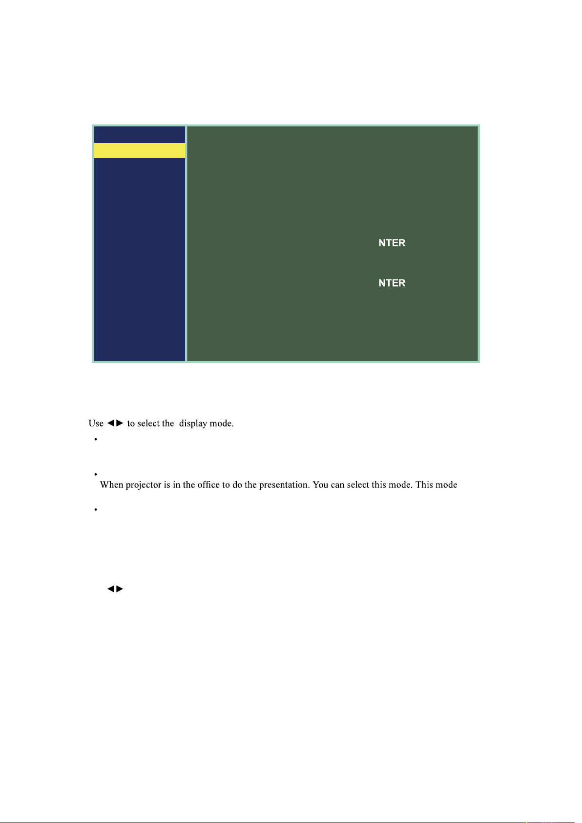
Picture Mode
High Bright
When projector in the high ambient light conditions. You can select this mode to get the high
brightness image Performance.
Presentation
brightness is between High Bright and Video.
Video
When projector in the low ambient light condition, You can select this mode to save power and
optimized image quality.
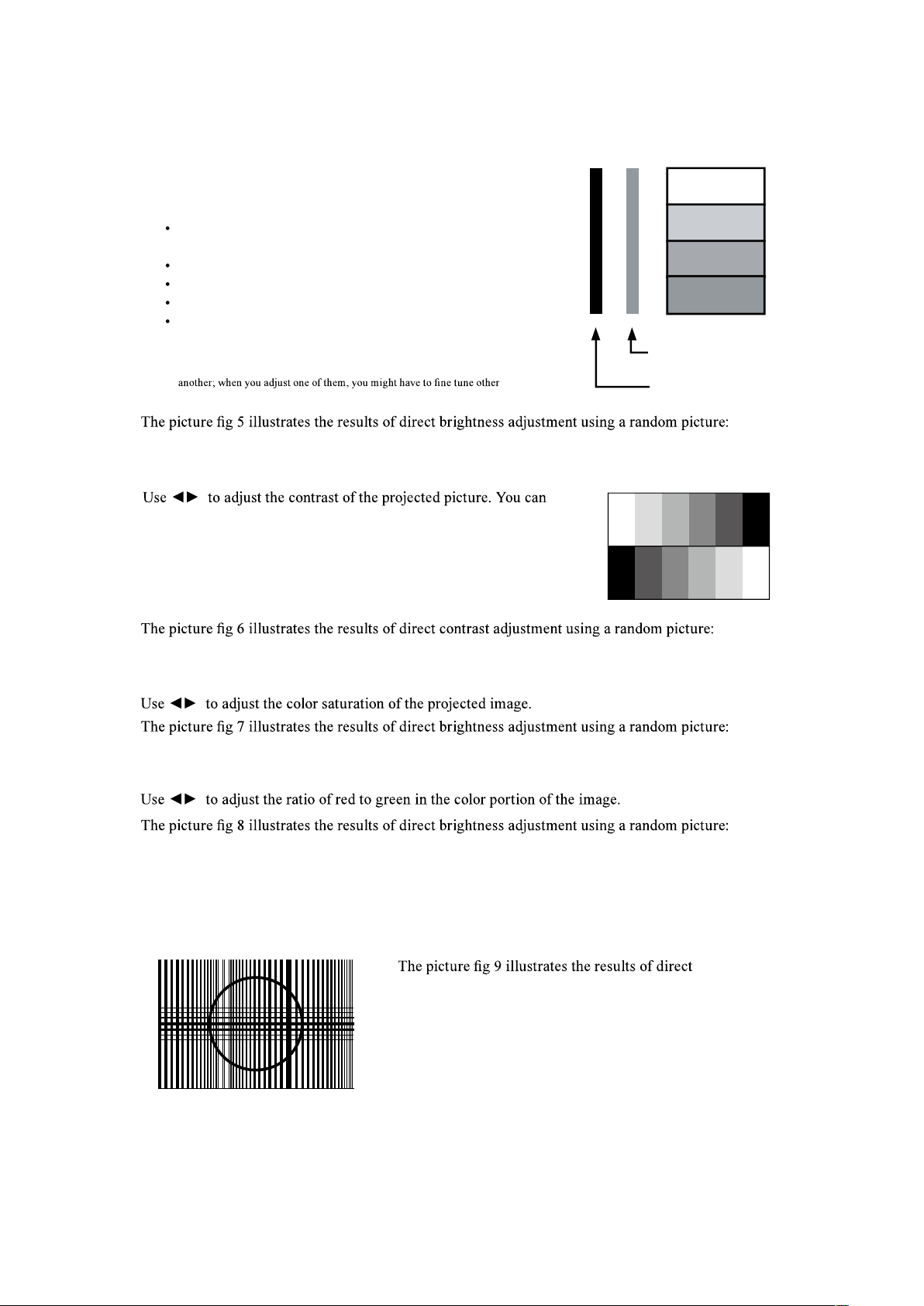
Brightness
Use to adjust the brightness of the projected picture. You can connect the projector to an external
picture source to display an picture resembling the one shown (PLUGE : Picture Line-Up Generation
Equipment) for adjustment. Although there are numerous versions of PLUGE picture, they are
typically comprised of blocks of black, white and gray on top of a black background.
English - 42
OSD Menu description
Contrast, Brightness, Color and Tint are interrelated options that affect one
settings to get the best projection results.
Above Black
Below Black
It is recommended that you adjust the picture to the
following status:
The darkest black bar of the picture should disappear
into the background.
The dark gray area should be barely visible.
The light gray area should be clearly visible.
The white area should appear real and mellow.
The picture should only display black, gray and white
(with no other colors).
Contrast
connect the projector to an external picture source to display an picture
resembling the one shown below for adjustment. It is recommended
that you adjust the projected picture according to the results shown
below so that the brightness of the spectrum remains constant
throughout and achieve maximum contrast between black and white.
Color
Tint
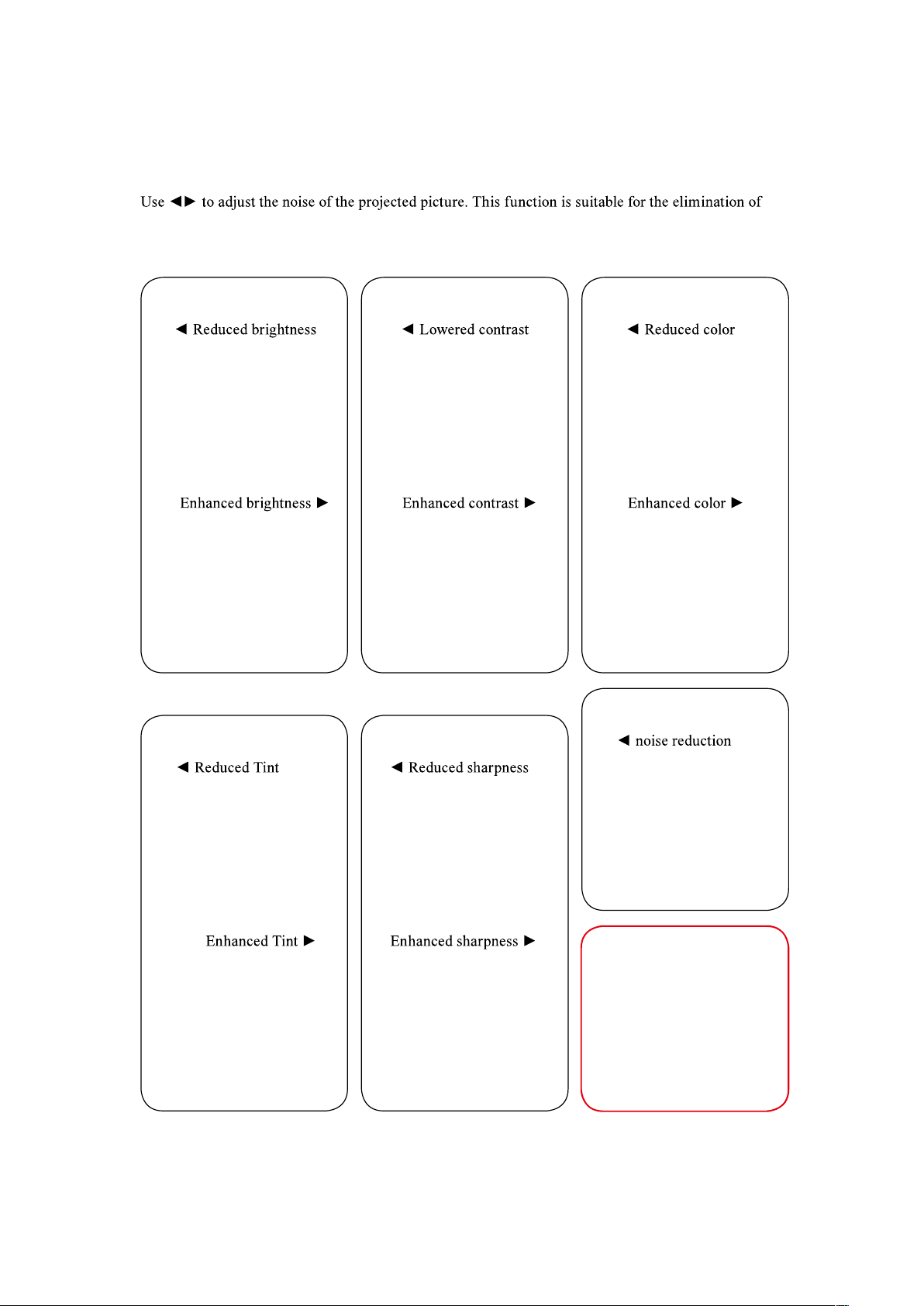
Sharpness
The adjustment of sharpness primarily changes the value of high frequency detail. You can connect
the projector to an external picture source to display an picture resembling the one shown below to
adjust the picture sharpness.
sharpness adjustment using a random picture:
English - 43
OSD Menu description
Noise Reduction
picture noise from interleaving SD input. Generally speaking, reducing picture noise will lower the
value of high frequency detail and make the picture appear more mellow. Refer to Fig 10.
Fig 5
Original picture
Fig 7
Fig 10
Fig 8
Fig 6
Fig 9

English - 44
OSD Menu description
Color Temperature
You can choose from 5400K, 6500K, 7500K, 9300K and Native.
Color temperature refers to the change in light color under different energies that is perceived by the
.
color temperature rises, the picture will appear to be bluer; as it decreases, the picture will appear
redder. When you choose “Native”, the projector will disable the white adjustment function of the
input device.
White Balance
Regardless of the change in ambient light, the human eye is equipped with an automatic adjustment
mechanism that makes a white object appears white and black object black. However, since no
machine has such an incredible innate feature, you may need to make certain adjustments to the
colors.
Offset
This refers to the control of color imbalance in the darker areas of the projected picture. It is
recommended that you use an external test picture with many areas of dark and gray colors (i.e. an
picture of 30IRE-window). If you notice minimal amount of red, green or blue in the gray areas, adjust
the offset of the corresponding color accordingly. This function will shift the entire color spectrum for
the whole picture and change its brightness.
Gain
This refers to the control of color imbalance in the brighter areas of the projected picture. It is
recommended that you use an external test picture with many areas of white (i.e. an picture of 80IRE-
window). If you notice minimal amount of red, green or blue in the gray areas, lower the gain of the
corresponding color accordingly. This function is used to increase or decrease the range of color input
for the entire picture.
Generally speaking, as gain increases, the contrast of the picture will become lower. By increasing the
offset, the picture brightness will become lower.
Red Offset
Green Offset
Blue Offset
Red Gain
Green Gain
Blue Gain
English - 45
OSD Menu description
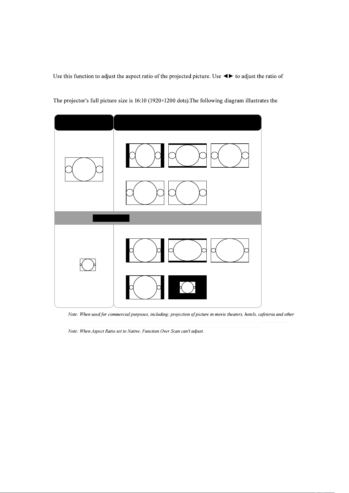
Aspect
picture length and width.
difference in various aspect ratio settings:
16:10
16:10
Normal Native
Normal Native
4:3 16:9
4:3 16:9
16:10
(1920*1200)
4:3
(800*600)
Native input Output aspect ratio
Cropped portion of the image
public venues, compression or extension of picture achieved through the change of aspect ratio may constitute
copyright infringement to the rightful owner of the picture. Please do so at your own discretion.
English - 46
OSD Menu description
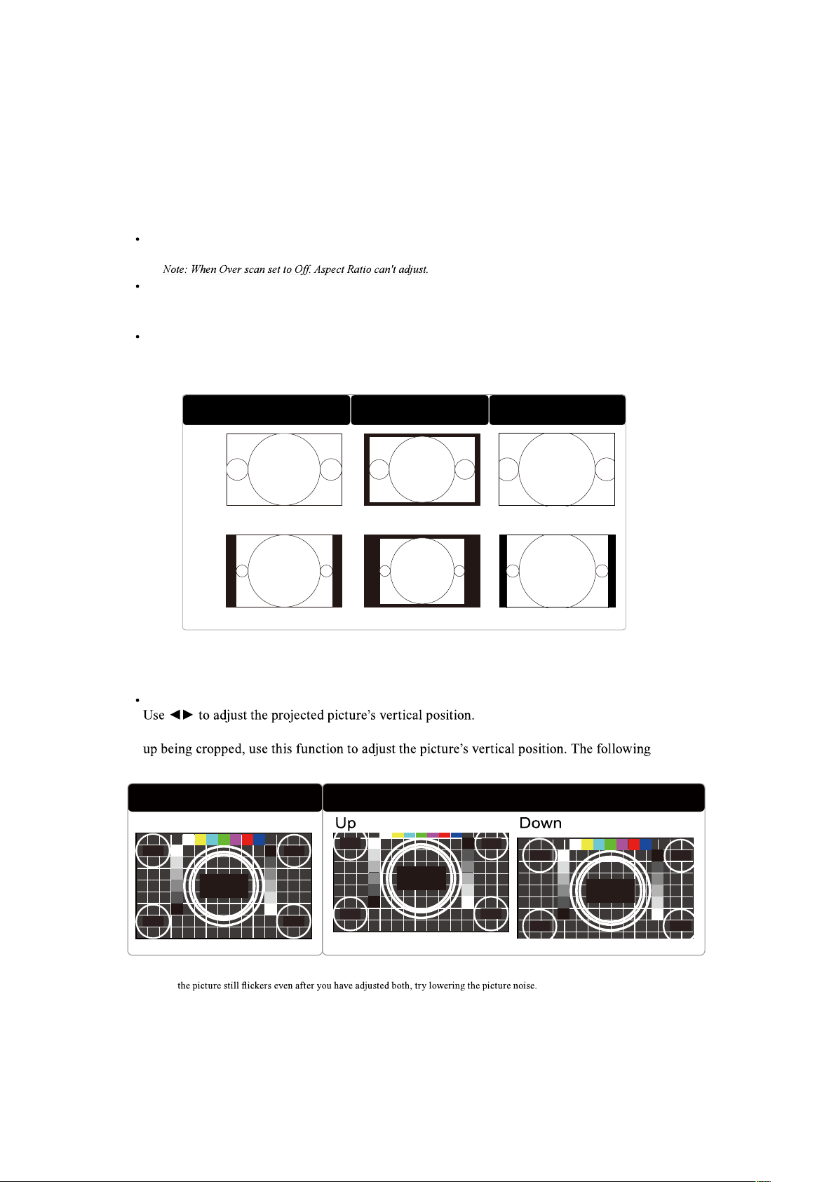
Over Scan
Due to the fact that some consumers may still be using older television systems, some TV programs
may not display the edges of the picture. Use this function to hide the picture edge by choosing one of
the following three options:
Off
Setting it to off makes no change to the projected picture.
Crop
Setting it to "Crop" will add two "masks" equivalent to 3% of horizontal resolution on either side of
the picture and two similar masks above and below the projected picture.
Zoom
You can use this function to enlarge the picture's horizontal resolution over the 106% of the default
aspect ratio. Any portion that exceeds the original picture will be cropped.
16:10
Off Crop Zoom
4:3
Position and Phase
V Position
If the projected picture is not at the center of the screen (i.e. shifted up or down) and ends
picture is an example of test picture from an external signal source:
It is recommended that when adjusting the picture, the horizontal total should be adjusted before the horizontal phase. However, if
English - 47
OSD Menu description
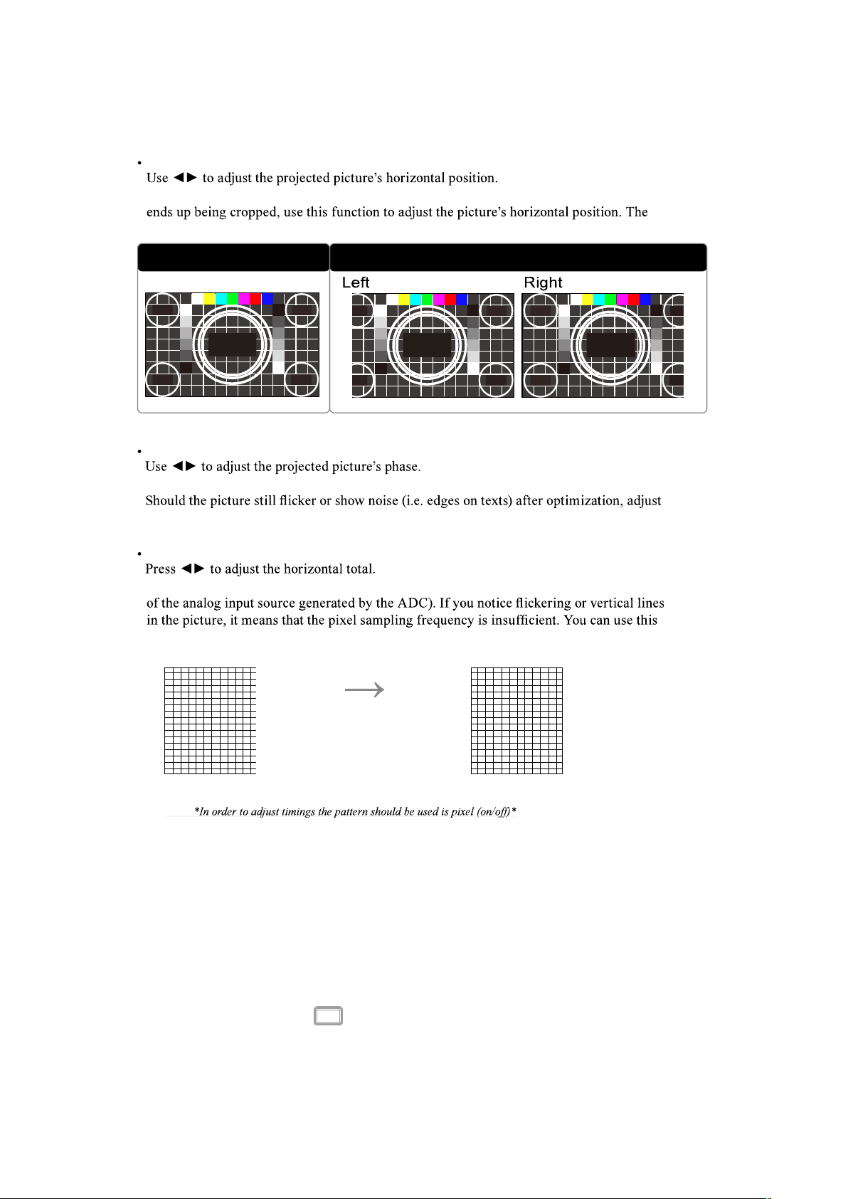
H Position
If the projected picture is not at the center of the screen (i.e. shifted to right or left) and
following picture is an example of test picture from an external signal source:
Native picture Skewed
H Phase
Use this function to adjust the phase of pixel sampling clock (relative to input signal).
phase accordingly.
H Size
Use this function to adjust the clock frequency of pixel sampling (horizontal pixel frequency
function to adjust the frequency to achieve consistent picture quality.
The following picture is an example of test picture from an external signal source:
Adjust picture quality by changing
the value of horizontal total to
smoothen the picture.
Auto Adjust
When Auto image was selected in the OSD menu, press ENTER to execute the automatic picture
adjustment function.
By executing this function, the projector will resync the picture. Use this function when the
picture source is unstable or when you notice deterioration in picture quality and the projector will
automatically adjust the picture size, phase and timing. (The adjustment also applies to PinP input
source).
This function is identical to the
button on the remote control. You can simply use the hot key on
the remote control to execute this function.
English - 48
OSD Menu description
LASER
MAIN
PICTURE
LASER
ADVANCED
SETUP
SERVICE
Power Mode
Power Level
High Altitude
Custom
20%
Normal
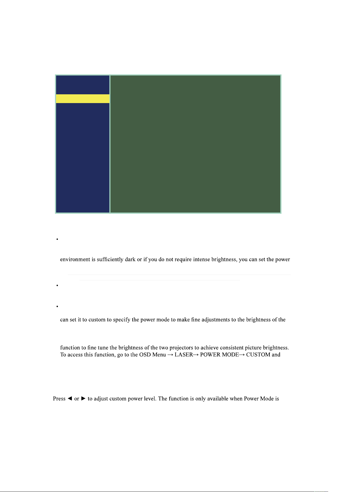
Power Mode
ECO
When set to Eco mode, the brightness will 80% of the normal brightness(Operature temperature
must lower then 35°C. The cooling fan will auto slow down the speed. If the surrounding
mode to Eco to save the power.
Note: ECO is automatically selected between 35~40°C(95~104°F), when the temperature is higher then 35°C. The fan
speed will fully operational to exhaust the heat. This situation will not save the power.
Normal
Brightness will 100%. When set to Normal mode. If the projection environment requires brighter
picture, you can set the power mode to Normal for the highest projection brightness.
Custom
If the picture brightness at Eco mode is too dark for you and the Normal mode gets too bright, you
projected picture. you could encounter situations where the picture from projector A being brighter
than projector B. When this occurs, you can use this function you could encounter situations where
the picture from projector A being brighter than projector B. When this occurs, you can use this
adjust accordingly.
Power Level
Custom.

English - 49
OSD Menu description
High Altitude
Use this function to control the projector's cooling fan. You can set it to Off or On. The default setting
is Off.
Under normal circumstances, the projector will operate normally with this function set to Off. By
default, the projector will detect the temperature of the surrounding environment to regulate the speed
of the cooling fan. When the ambient temperature rises, fan speed will increase (generates louder
noise) to make sure the heat inside the projector gets discharged and keep the projector working
normally.
However, if you were to operate the projector in environment of excessive heat or in areas of high
altitude, the projector may automatically shut down. When this happens, you can enable this function
by setting it to high altitude mode1 or 2 to force the cooling fan to work at a full speed to regulate the
temperature inside the projector. There has 4 different model can choise as following:
Normal
Suitable for 0 to 4000ft (0-1219M)
Operation temperture 0 ~35°C -> The Laser light power will 100% active.
Operation temperture 36~40°C-> The Laser light power will 80% active.
High 1
Suitable for 4000ft to 5500ft (1219-1676M)
Operation temperture 0 ~30°C -> The Laser light power will 100% active.
Operation temperture 31~35°C -> The Laser light power will 90% active.
Operation temperture 36~40°C -> The Laser light power will 80% active.
High 2
Suitable for 5500ft to 10000ft (1676-3048M)
Operation temperture 0 ~25°C -> The Laser light power will 100% active.
Operation temperture 26~30°C -> The Laser light power will 90% active.
Operation temperture 31~35°C -> The Laser light power will 80% active.
Operation temperture 36~40°C -> The Laser light power will 70% active.
Auto
The projector will automatically sensing the surrounding and will automatic switching the High
Altitude mode.
Note: Due to the air thinning substantially at high altitudes, the result of cooling achieved by the cooling fan is
temperature, the cooling fan will not be able to disperse the heat adequately
English - 50
OSD Menu description
ADVANCED
MAIN
PICTURE
LASER
ADVANCED
SETUP
SERVICE
Installation
Lens Control
Lens Memory
Lens enter
Gamma
Pattern
Color Management
Warping Blanking
Edge Blending
Memory Dynamic
Black
Front Tabletop
E
E
E
2.2
E
E
E
E
E
E
Off
Installation
Use these function to install the projection mode. Has below 4 mode can select:
Front Tabletop
Refer to " Page 25 : Front Tabletop " for detail information.
Font Ceiling
Refer to " Page 26 : Front Ceiling " for detail information.
Rear Tabletop
Refer to " Page 26 : Rear Tabletop " for detail information.
Rear Ceiling
Rear to " Page 26 : Rear Ceiling " for detail information.
Lens Control
Zoom
This function is identical to the one covered in previous sections. Refer to " Page 23 : 7.
Adjusting the projector's angle, Lens Shift, Zoom and Focus ".
Focus
This function is identical to the one covered in previous sections. Refer to " Page 23 : 7.
Adjusting the projector's angle, Lens Shift, Zoom and Focus ".
Shift
This function is identical to the one covered in previous sections. Refer to " Page 23 : 7.
Adjusting the projector's angle, Lens Shift, Zoom and Focus ".
Note: The lens control is related with lens centering. Refer to " Page 51 : Lens Centering " for more information.
English - 51
OSD Menu description
Lens Memory
This projector can save 10 sets of lens position information (including Focus, Zoom and Lens shift
setting). No matter how you adjust the lens , you can call these lens memory to restored the lens
position setting that you record in the OSD.
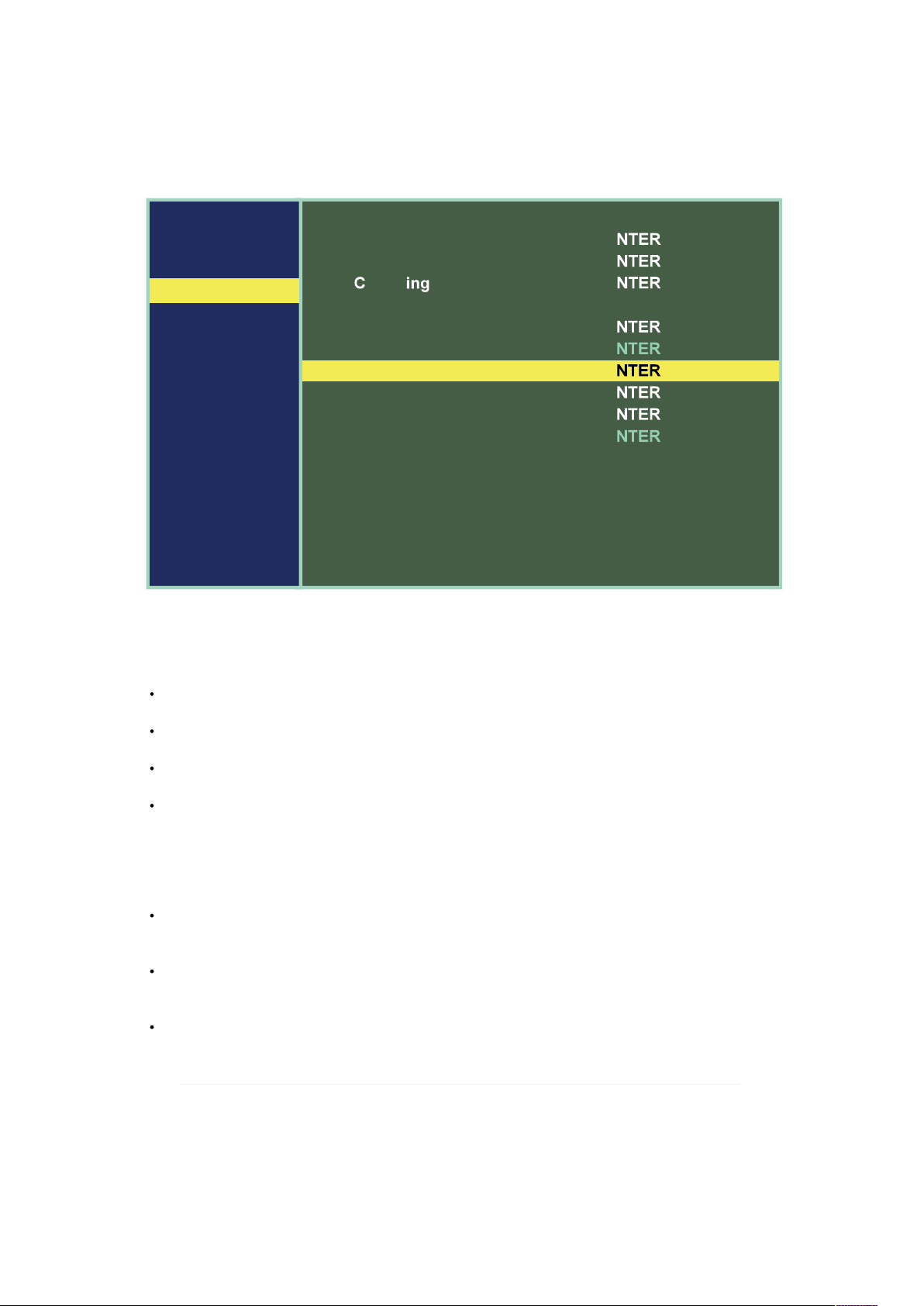
Load Memory
Select this item to load the your own setting for lens.
Save Setting
lens.
Clear Memory
Clear setting lens memory data.
Lens Centering
After series of lens shift operations, this function can be used to return the lens to the center
position. This function need about 2 minutes. During the lens centering adjustment period. If you ask
the projector to execute other instructions and cause the lens centering adjustment interrupt, or such
as suddenly power failure....etc. Next time when you open on the projector or execute lens control
function. The projector will pop on a warning message to ask execute Lens Centering again to force
the lens to center. Then you can opterate the lens other adjustment. If you execute Lens Centering.
Suggest you not to Interrupt the execution of this action.
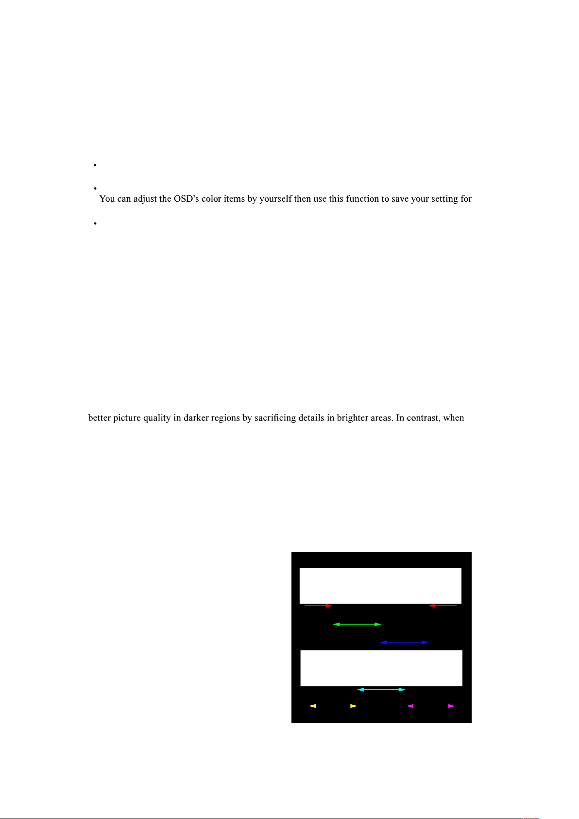
Gamma
Using different color gamut will create different color presentation in the projected picture. Generally
speaking, when the surrounding are darker, it is recommended that Gamma be set higher to yield
projecting brighter pictures, you can set the Gamma lower to give up details in the darker areas to
make the brighter areas more visible.
You can choose from the following color gamma: 1.0 / 1.8 / 2.0 / 2.2 / 2.35 / 2.5 / DICOM SIM.
Pattern
The projector comes with some standard built-in patterns for testers to calibrate the equipment.
These include: White / Black / Red / Green / Blue / Checkerboard / CrossHatch / V Burst / H Burst /
ColorBar.
Color Management
Correct the color for all signals via adjusts
the Hue/Saturation/Gain value of the Red,
Green, Blue, Cyan, Magenta, Yellow and
White.
Hue
Red 100 200 Red 1000
Green 100 2000
Blue 100 2000
Cyan 100 2000
Yellow l00 2000 Magenta 100 2000
English - 52
OSD Menu description
Warping
The function provides distortion correction on projected pictures.
Keystone
Please refer to " Page 23 : 8. Correcting keystoning caused by projection angle "
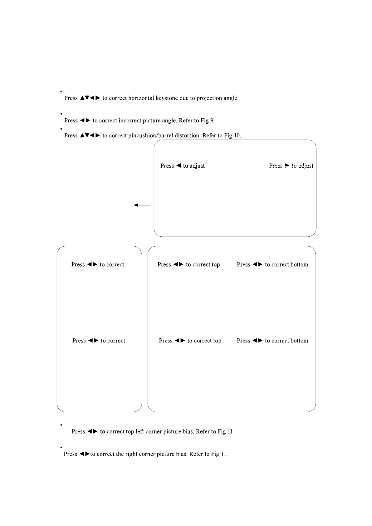
Rotation
Pincushion / Barrel
Original picture
pincushion distortion
barrel distortion
Fig 10
left corner picture bias
left corner picture bias
Fig 11
Fig 9
left corner picture bias
right corner picture bias
After
Adjust
Top Left Corner
Top Right Corner
English - 53
OSD Menu description
Bottom Left Corner
Bottom Right Corner
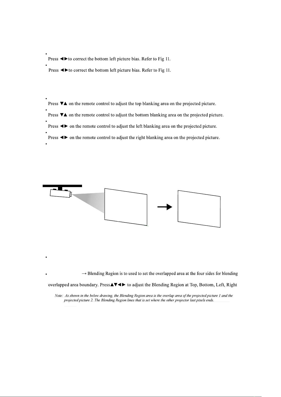
Blanking
TOP
Bottom
Left
Right
Reset
It will reset all the blanking functions to the default settings that is without any blanking functions
enabled.
Use Right and Top blanking function to
block the additional picture on the screen.
Edge blending
Status
Press ENTER to select ON or OFF. The function must be set to ON in order to enable the
function of Edge blending. If the function is set to OFF, the function of Edge blending is disabled.
Blending Region
in multi-projection application. Adjusted lines, when enabled, will be shown for indicating the
directions on the projected picture.
English - 54
OSD Menu description
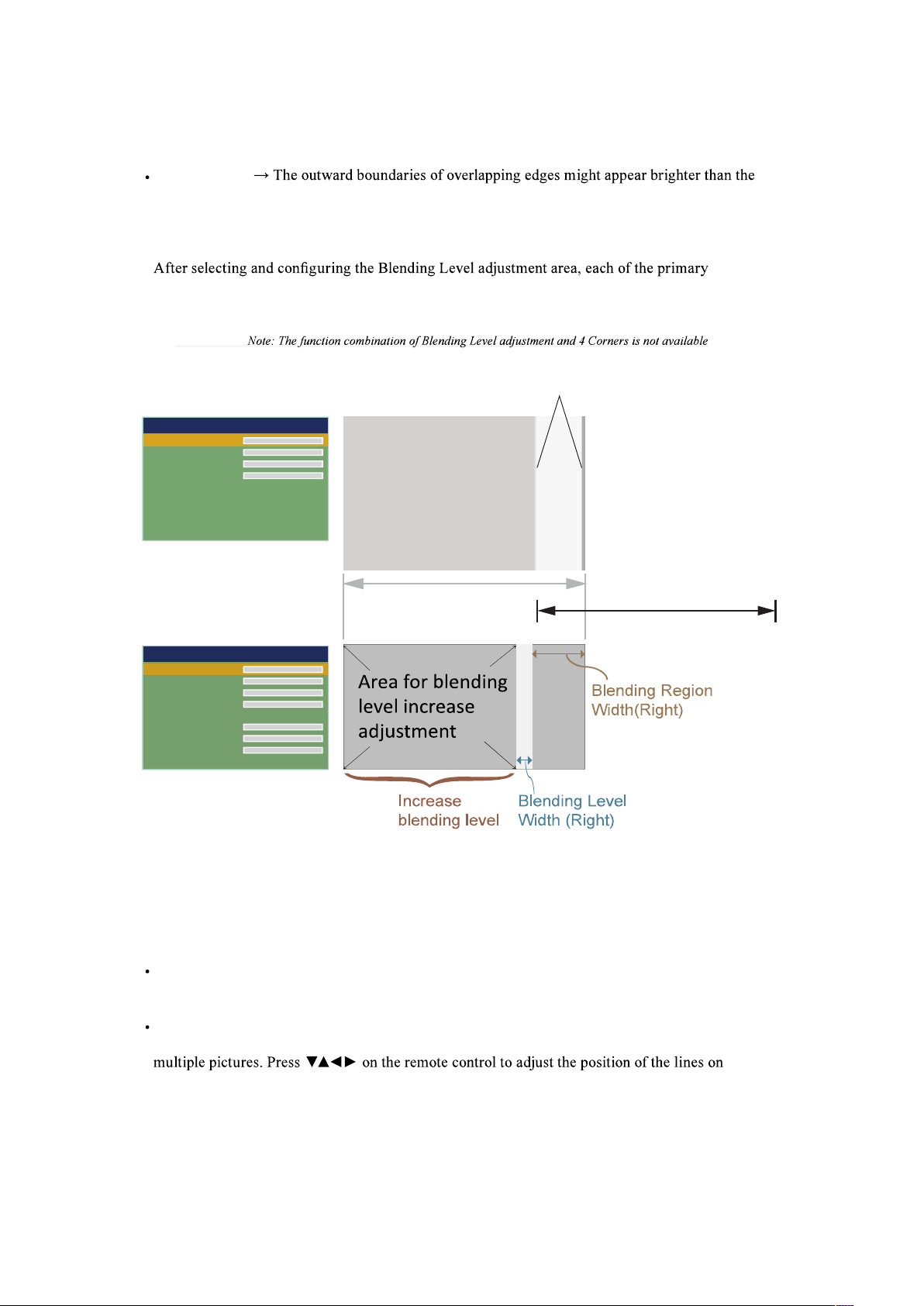
Blending Level
rest of the image due to the lumens at the inactive DMD display area. The purpose of Blending
Level is compensate the non overlap area vs the overlap area. It increases the Blending Level of non
overlap area .It is used to adjust the Blending Level at Top, Bottom, Left, Right directions on the
projected pictures.
colors Red, Green, Blue can be adjusted to increase to a higher Blending Level independently,
or optionally All colors together can be adjusted to increase to a higher Blending Level
simultaneously.
Blending Region
Top
Bottom
Left
Right
0
0
0
0
Blending Region Lines
Image 1
Image 2
Blending Level
Top
Bottom
Left
Right
All
Red
Green
Blue
0
0
0
0
0
0
0
A black image is required to connect to the multiple projectors to be blended for the Blending Level
adjustment. For projector projecting Image 1, Set the adjustment line of the Blending Level to the
position
where the in active DMD's of another projector ends, for example: Adjust Blending Level
of projector corresponding to Image 1 to match the Blending Level of inactive DMD display area of
another projector. And performing the same adjustment on the projector corresponding to Image 2.
Reset
The function
can reset the Edge blending settings on the projector. It will restore to the
pictures to the default that is without any Edge blending functions enabled.
Adjust Lines
When the function is ON, there will be adjust lines on the picture in order to easily adjust
When the function is ON, there will be adjust lines on the picture in order to easily adjust
the picture.

English - 55
OSD Menu description
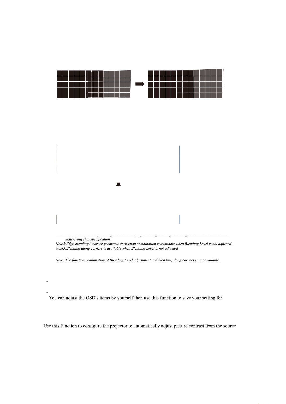
The picture below is an example if 2 projectors are projecting at the same picture.
1.
Horizontally place two projectors and have the two projected pictures with an overlap area and use the focus/zoom and
lens shift functions with test grid pattern to set a
proper overlap area for blending with a matched grid size.
2.
Color matching 2 projectors on white is done with Custom Color Space at ALIGHNMENT menu.
3.
Brightness matching 2 projectors can be done with the lamp power(Refer to adjustment by dimming the projector with
higher lumens.
4.
Use Edge blending-> Blending Region to set the blending size based on the overlap region size.
Use Edge blending-> Blending Level position to adjust the start position of Blending Level compensation.
Use Edge blending-> Blending Level to raise the brightness of non-overlap zone such that the brightness of the overlap
zone and non-overlap zone are matched for Blending Level.
Note1:Please note that the following allowable warping, blanking and Edge blending combination based on the
Note1:Please note that the following allowable warping, blanking and Edge blending combination based on the
Memory
Load Memory
Select this item to load your own setting for projector.
Save Setting
projection.
Dynamic Black
upon start up or shut down. When activated, the projector will dynamically adjust the picture contrast
from the beginning of the projection until the content has ended.
Available while black image signal inputting.
This function might not work correctly, in the case of Analog signal with noise.
English - 55
OSD Menu description
The picture below is an example if 2 projectors are projecting at the same picture.
1.
Horizontally place two projectors and have the two projected pictures with an overlap area and use the focus/zoom and
lens shift functions with test grid pattern to set a
proper overlap area for blending with a matched grid size.
2.
Color matching 2 projectors on white is done with Custom Color Space at ALIGHNMENT menu.
3.
Brightness matching 2 projectors can be done with the lamp power(Refer to adjustment by dimming the projector with
higher lumens.
4.
Use Edge blending-> Blending Region to set the blending size based on the overlap region size.
Use Edge blending-> Blending Level position to adjust the start position of Blending Level compensation.
Use Edge blending-> Blending Level to raise the brightness of non-overlap zone such that the brightness of the overlap
zone and non-overlap zone are matched for Blending Level.
Note1:Please note that the following allowable warping, blanking and Edge blending combination based on the
Note1:Please note that the following allowable warping, blanking and Edge blending combination based on the
Memory
Load Memory
Select this item to load your own setting for projector.
Save Setting
projection.
Dynamic Black
upon start up or shut down. When activated, the projector will dynamically adjust the picture contrast
from the beginning of the projection until the content has ended.
Available while black image signal inputting.
This function might not work correctly, in the case of Analog signal with noise.
English - 56
OSD Menu description
SETUP
MAIN
PICTURE
LASER
ADVANCED
SETUP
SERVICE
Network
OSD Settings
Infrared Remote
Remote ID
Startup Logo
Trigger
Auto Search
Auto Power Off
Direct Power On
Language
AMX D.D
E
E
On
0
On
Screen
Off
Off
OFF
English
Off
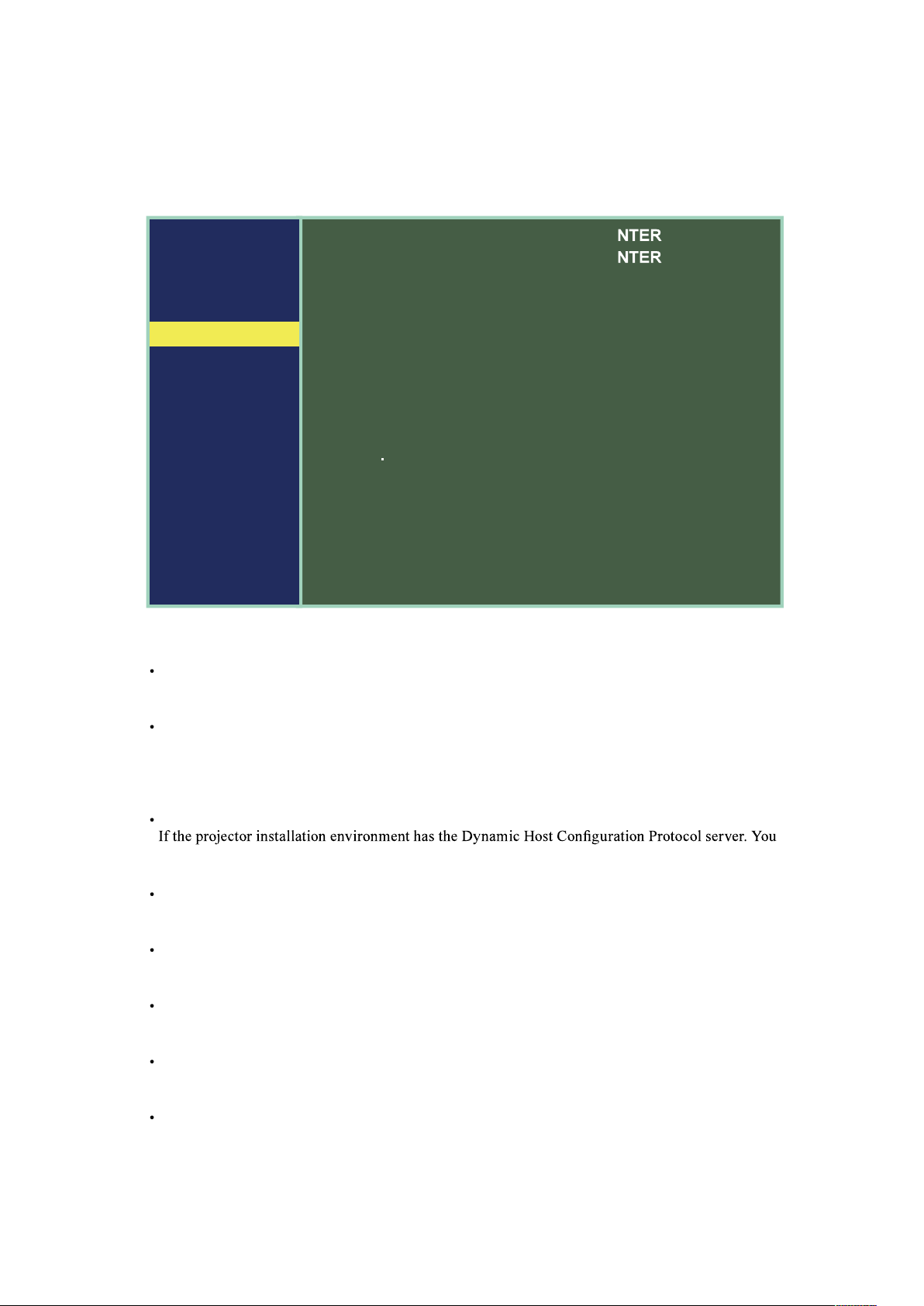
Network
Network Mode
Projector Control : Choice this fuction to control the projector via the web.
Service : This function only for the professional service person. For download command use.
Standby Power
Off : Set off, Power consumption 0.5W. Can't operate the projector via the web when projector is in
standby mode.
On: Set on, Even if the projector is in standby mode, you can control the projector via the web.
Power consumption is more than "Off".
DHCP
can set this function "ON" to let the projector get the auto ID from server. If no DHCP, even you set
"ON" for this function. You still need to input the projector ID by yourself.
IP Address
If has DHCP server and the function is on. The ID address will auto display here , or you need to
enter ID by yourself.
Subnet Mask
If has DHCP server and the function is on. The Subnet Mask address will auto display here , or you
need to enter it value by yourself.
Gateway
If has DHCP server and the function is on. The Gateway address will auto display here , or you
need to enter it value by yourself.
DNS
If has DHCP server and the function is on. The DNS address will auto display here , or you need to
enter it value by yourself.
MAC Address : Read only.

English - 57
OSD Menu description
OSD Setting
Menu Position
You can use this function to designate which area on the picture the OSD Menu will appear. As
Menu displayed. The default setting is “Center”.
Time Out
Choice one value to display OSD on the screen time.
Message Box
Machine will auto display the input signal message on screen if you select on. If you don't want to
disable the message, please select off.
Infrared Remote
If you want to control the projector by Web, LAN or RS232. Suggest you set this function "Off" to
prohibit control the projector via the infrared remote control.
Remote ID
the remote ID by remote control directly - refer to " Page 33 : Remote control " -ID Set. for detail
message.
Note: This feature is disabled if the device is setting 00 to be the initial value.
Start up logo
You can use this function to have the projector display the HITACHI logo in the start up screen. Set
On to display the HITACHI logo during start up and Off to display a blank picture.
If you hope to disapper the logo while no input detect, you had better change setting as page 40 "No
Signal".
Trigger
trigger ports to be automatically turned on when the projector is on. There will be a 2-3 second delay
prior to activation to prevent operation of this function when the user is choosing the desired aspect
ratio.
Screen Outputs 12V of power on Trigger when the user open the projector screen.
4:3 Outputs 12V of power on Trigger when the user chooses the 4:3 aspect ratio.
16:10 Outputs 12V of power on Trigger when the user chooses the 16:10 aspect ratio.
16:9 Outputs 12V of power on Trigger when the user chooses the 16:9 aspect ratio.

English - 58
OSD Menu description
Auto Search
ON
By enabling this function, the projector will automatically determine the source of input every time
it is turned on so that the user will not have to make the selection on the OSD Menu.
OFF
Setting the function off will require the user to specify source of picture input on the OSD Menu in
order for the projector to display the intended picture.
Auto Power Off
The default value is OFF. If you set it to ON, the projector will automatically shut down after 20
minutes without any input signal.
Direct Power On
The default value is Off. If you set it to ON, the projector will automatically start up when it is
you do not need this function, please set it to Off.
Note: When the standby power set off. Even direct AC off, the LED Light still keep lighting until 25seconds. During this
period, the machine maybe can't power on normally.
Language
You can use this function to select the language you wish for the OSD Menu to be displayed in. You
can choose from the following nine languages:
Traditional .
AMX D.D.
Support AMX device discovery.
Connect to http://www.amx.com/ get more information of this projector.
Web control/ Crestron Control
You can use "Web Control” function
including “Crestron Control" on this
projector.
To access the projector via the network from
your PC, input projector's IP address to
browser URL after network setting.(Refer
page 56)
For example: http://192.168.0.100/
Then you can access "Web Control" page.
"Crestron Control" is available by selecting
its sheet.
Further information about Crestron,
refer to http://www.crestron.com
PS: IP address is the one of your projector. For example: http://192.168.0.100/Crestron/PJeControl.html
....etc.
Recommended web browser : Internet Exprorer
®
10/11.
Web browsers other than recommend ones may not work.
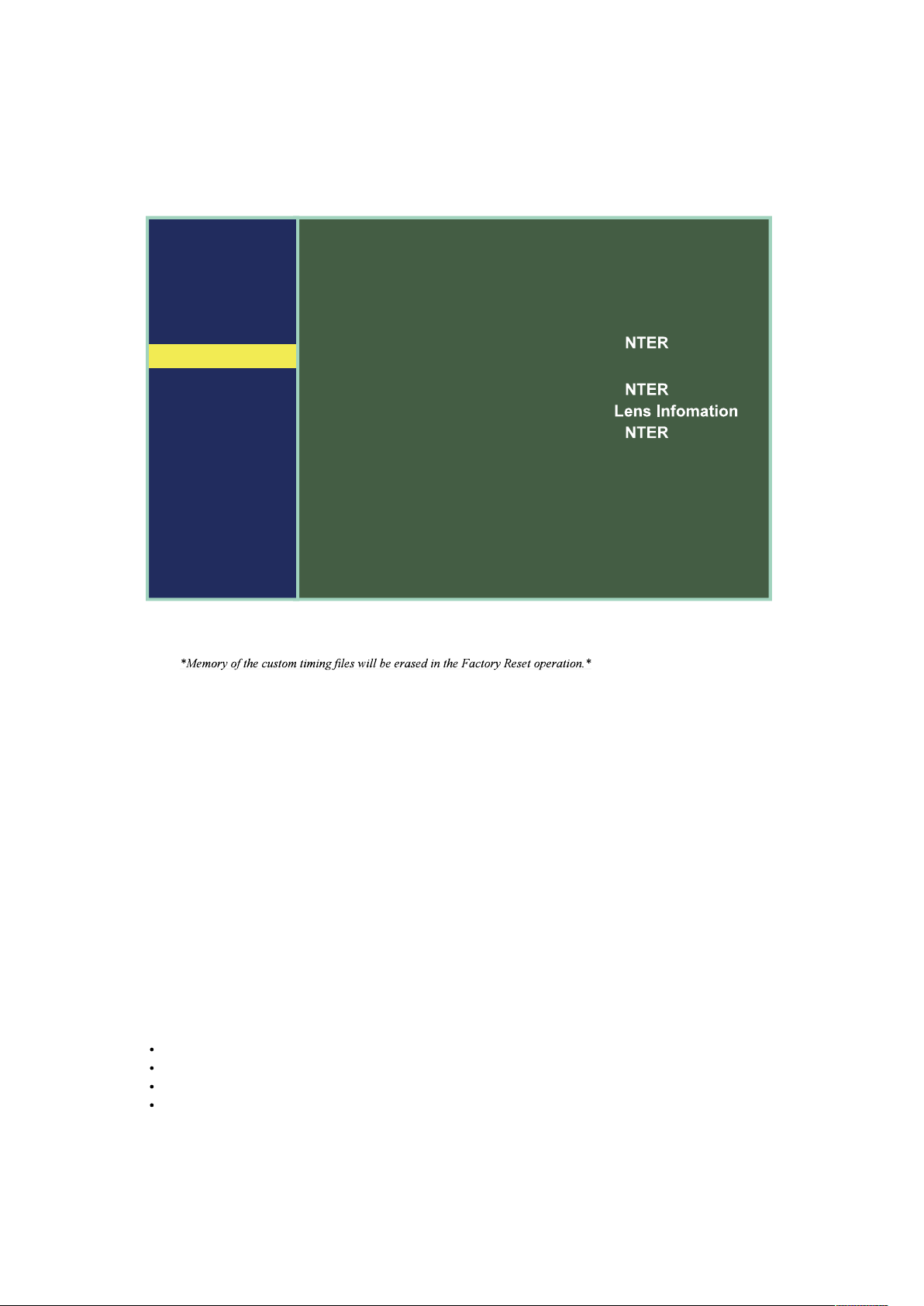
English - 59
OSD Menu description
SERVICE
MAIN
PICTURE
LASER
ADVANCED
SETUP
SERVICE
Model Name
Seria Number
Software Version 1
Software Version 2
Actives Source
Signal Format
Laser Hours
Thermal Status
Factory Reset
LP-WU9750B
W529ZARCY0025
ME14v1-NA-FE09
LE07-14-RE02v1-3092
DVI-D
E
00000 HRS
E
E
The functions covered in this unit relate to the display of some basic information about the projector.
Model Name
the designated model number of the projector.
Serial Number
The designated serial number of the projector.
Software Version 1 / 2
The version of software installed on the projector.
Active Source
Displays the current input sources.
Signal Format
Displays the format of the current input signal.
Timing: displays the Timing of the current input signal.
H Freq: displays the horizontal Frequency refresh rates for the current picture.
V Freq: displays the vertical Frequency refresh rates for the current picture.
Pixel Clock: displays the pixel clock of the current input signal.

English - 60
OSD Menu description
Laser Hours
displays Laser module current usage time.
Thermal Status
Display the thermal sensor current temperature, include Intake , DMD and Laser.
Lens Information
Lens Information Displays the lens ID and Lens name.
Factory Reset
this function will not apply to items including no signal, network, Projector control, startup Logo,
language, High Altitude mode and lamp hours.
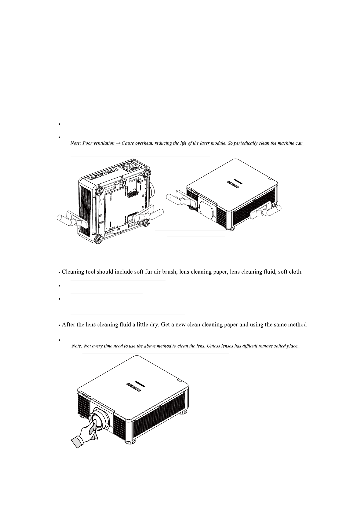
English - 61
Cleaning
Cleaning
Turn off the projector and unplug the power before cleaning. Suggest to wait at least 45 minute to let
the projector cool down.
Cleaning the Cabinet
Use a dry soft cloth to wipe off the cabinet dust.
Note: Not suggest to use cleanser. If too dirty, only use little neutral detergent to clean the cabinet.
Use a vacuum cleaner to clean the cabinet.
extended machine service life.
Note: Need to clean the interior of machine, please contact your dealer
Cleaning the Lens
You can buy these items from the Camera stores.
Use soft fur air brush to blow off dust on the lens surface. Then Gently brush the surface dust.
Note that the action should be gentle
Fold the lens cleaning paper and add few drops of cleaning liquid on paper, follow the clockwise or
counterclockwise direction to wipe lightly from Center to outside.
Cleaning liquid can't be added directly to the lens surface.
To avoide scratch the lens, do not wipe straightly back and forth.
to clean the lens.
Finally, wipe the lens with a soft cloth.
Otherwise, only use soft fur air brush to remove dust on the lens is enough.
Otherwise, only brush to remove dust
on the lens with air is enough
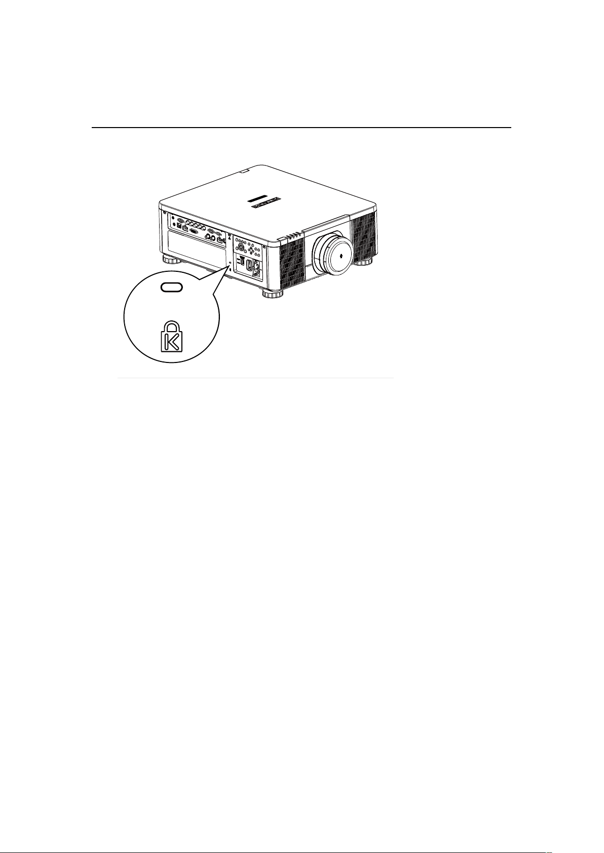
English - 62
Kensington
Using the Kensington
®
Lock
Worry about the security of the projector. You can use Kensington lock the projector to avoid the it be
stolen.
Note: For Kensigton lock detail installation inormation. Please contact to the dealer.
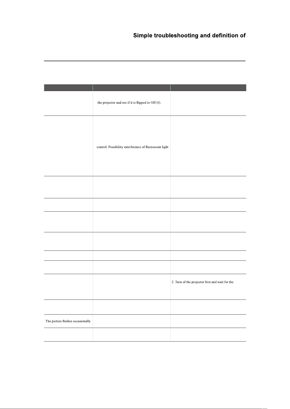
English - 63
the LED indicators
Simple troubleshooting
The following table offers a list of common problems with projectors and how to troubleshoot. If the
recommended solutions fail to resolve your problem, contact your local dealer to arrange for servicing;
do not attempt to service the projector by yourself.
Problem Possible cause Solution
You cannot turn on the projector
1. The projector may be unplugged
2. Check the AC POWER SWITCH on the back of
3. The AC socket may be faulty
4. The lens is not attached.
1. Plug the projector's power cord into a wall outlet
2. Flip the power switch to "ON (1)".
3. Make sure the AC socket is working properly.
4. Mount the lens.
The remote control does not
operate normally
1. The battery might have run out
2. You might have inserted the batteries in the wrong
orientations
3. You may be operating the remote control too far
away from the projector's IR sensor or exceeded the
maximum angle of signal reception ; there might be
an obstacle between the projector and the remote
or direct sunlight.
4. Ø 3.5mm A wired remote connector might be
connected to the projector's 3.5mm port.
5. The remote control's address is not consistent with
the projector's address
6. Remote control is disabled by OSD menu .
1. Replace new batteries
2. Make sure the batteries are inserted in the right
orientation.
3. Adjust the distance/angle between the projector
and the remote control and try again; if there are
obstacles between the projector and the remote or
source of intense light near the IR sensor resolve
these situations and try again.
4. Remove the wired remote cable or operate the
projector using wired remote.
5. Refer to " Page 57 : Remote ID " for detail
information.
6. Change "Infrared Remoto" setting on OSD menu.
You are able to turn on the
projector and access the OSD
Menu but no picture appears.
"Blanc function maybe available"
1. The projector may not be turned on properly or
you have not selected the correct input source.
2. You might not have connected the source device
correctly or the source might not be connected to
the projector at all.
1. Make sure the projector is turned on properly and
select the correct input source.
2. Check the connection between the projector and
the input device.
You can turn on the projector.
But projector display nothing on
screen.
No image on screen. Only the sound of the machine
operation.
Press "BLANK" of the remote control.
You have connected the
projector to a DVD player as
the input source but the picture
appears broken or PbyP in
halves.
The DVD player is connected to the projector
through component cables and you have set it to
progressive scan.
Disable the progress scanning function on the DVD
player.
The picture looks dim
1. The picture brightness, contrast, color and tint
might need proper adjustment.
2. The laser setting lower power mode
1. Adjust the picture brightness, contrast, color and
tint.
2. Refer to " Page 48 : Power Mode " to adjust the
power mode.
The picture is too bright or the
bright areas are blurry
The contrast might have been set too high. Lower contrast settings.
The picture appears washed
out or the dark areas appear too
bright
The picture brightness might have been set too high. Lower brightness settings.
The picture is blurry
1. The lens may not be in focus.
2. The temperature or humidity of the projector's
working environment may have changed in mid
operation (i.e. going from cold to warm or dry to
humid), leading to condensation of moisture inside
the projector.
1. Adjust Lines focus.
moisture in the projector to evaporate.
The color of the picture looks
pale
1. The input signal type might not have been
connected properly
2. The Color is not correct setting.
1. Check to make sure that the connections between
the projector and the input device are correct.
2. Press Menu to adjust the color related setting.
1. The cables might not have been properly connected
or the input device itself may be faulty.
1. Make sure the connector and the input device
have been properly connected; check to see if the
input device is in normal working order.
The colors of the projected
picture are out of place (i.e.
displaying red as blue)
The G/Y, R/Pr, B/Pb cables from the input might
have been incorrectly connected to the input.
Please make sure the input source has been
correctly connected to the projector.

English - 64
the LED indicators
Problem Possible cause Solution
The noise from the cooling fan
suddenly grew louder
1. The temperature inside the projector might have
risen.
2. The OSD Menu set the Higt Altitude Mode
1. When the temperature inside the projector rises,
the cooling fan will operate at a higher speed to
discharge the internal heat more rapidly.
2. Set the High Altitude mode to Off or Auto if the
projector is under 4000ft.
Refer to " Page 49 : High Altitude "
The LED indicator on the
in red
The cooling fan, power....etc. could be faulty.
STATUS "
1. During projection, the light
suddenly goes off and the
picture disappears.
2.The lights does not turn on
even when the projector has
been turned on.
The light module might have been damaged; check
the LED indicator on the rear panel of the projector
and see if it is blinking in red.
The light meodu has reached the end of its service
life; please replace it.
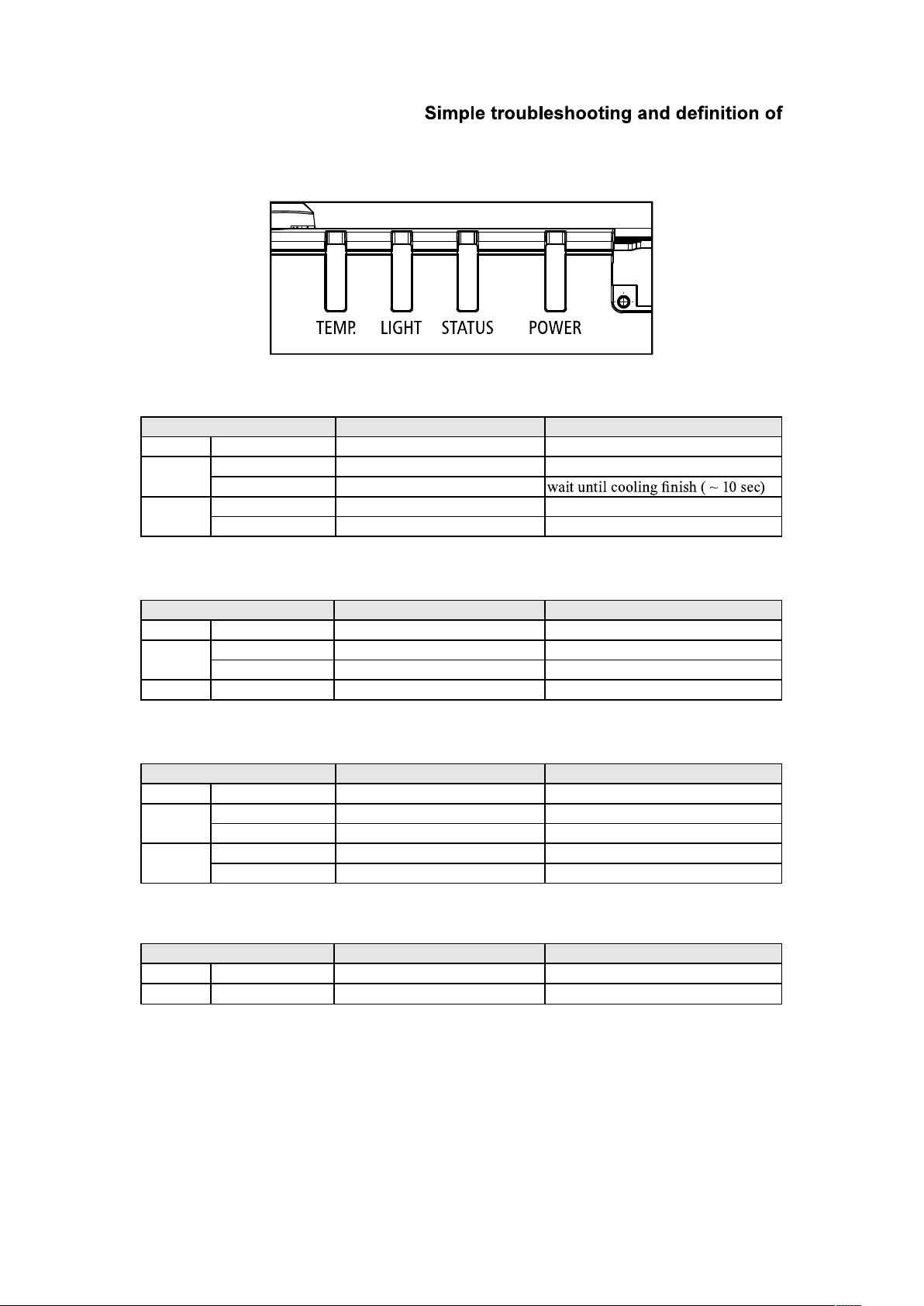
English - 65
the LED indicators
LED STATUS
Power LED
LED Display Projector Status Procedure
Off Power is off
Flashing
Green Prepare to turn on projector wait till projector start displaying
Orange Projector cooling
On
Red Standby mode
Green Projectpr is on
Status LED
LED Display Projector Status Procedure
Off No Problem
Flashing
Red (Cycles of 1) Prepare to turn on projector Use "op prerr" to see detail
Red (Cycles of 4) Projector cooling Use "op prerr" to see detail
On Red Standby mode Use "op prerr" to see detail
Light LED
LED Display Projector Status Procedure
Off Laser is off
Flashing
Green Prepare to light laser
Red (Cycles of 6) laser lit fail
On
Red Laser is end-of-life
Green Laser is on
Temp. LED
LED Display Projector Status Procedure
Off No Problem
Flashing Red Temperature problem Use "op prerr" to see detail
Remark:
The time period of each step in the above LED blinking pattern is 500 milliseconds, e.g., for “Cooling / Warm up” state, the
green LED will ON for 500 milliseconds, and then OFF 500 milliseconds, and then repeat the above LED pattern.
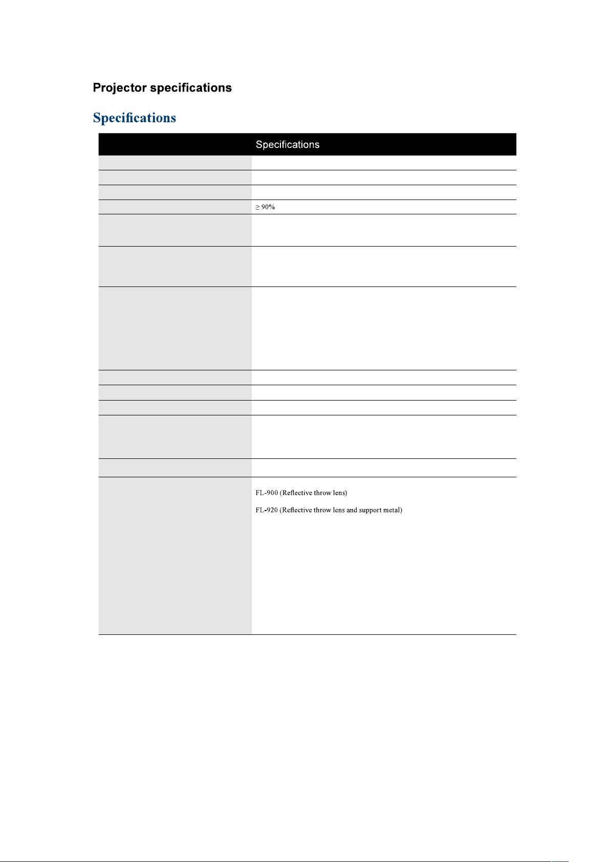
English - 66
Description
Resolution 1920 × 1200 (Native)
Micro display 1 x 0.67" WUXGA DMD
Contrast 1050:1(Native) / 10000:1 (Dynamic Black On)
Luminance uniformity
Lamp
Laser Diode:
Green and Red by laser phosphor
Blue by diffuse laser
Projection lens - projection ratio
FL-920 (0.32 : 1 100-350inch)
USL-901 (0.76~0.95 : 1 50-600inch)
SL-902 (1.14~1.72 : 1 50-600inch)
SD-903 (1.61~2.44 : 1 50-600inch)
ML-904 (2.38~3.64 : 1 50-600inch)
LL-905 (3.47~5.63 : 1 50-600inch)
UL-906 (5.53~8.79 : 1 50-600inch)
Input/Output ports
1 x 3.5mm Mini Jack for 12V Trigger
1 x Computer In (5BNC RGBHV/YPbPr/YCbCr)
1 x Computer In (D-SUB)
1 x RS-232
1 x Wire Remote
1 x HDBaseT/LAN
2 x HDMI
1 x DVI -D
1 x SDI(IN/OUT)
Primary voltage range 100V - 130V (±10%) / 200V - 240V (±10%)
Standby power consumption 0.5W max power when Standby Power setting is disabled
Maximum input resolution 1920 × 1200
Operating temperature
0~40°C
Note 1: The normal operating temperature of the DMD is between 10~65°C
Note 2: The DMD may operate normally for approximately 10 minutes under 0~10°C
short operation under such temperature will not result in DMD damage.
Weight 28 kg (Without PJ Lens, PD units)
Optional parts
Lens
FL-920 support metal
USL-901 (Short throw lens)
SL-902 (Short throw lens)
SD-903 (Standard lens)
ML-904 (Middle throw lens)
LL-905 (Long throw lens)
UL-906 (Ultra long throw lens)
Ceiling mount equipment
HAS-304H (Long ceiling mount)
HAS-204L (Standard ceiling mount)
HAS-104S (Short ceiling mount)
HAS-404U (Ceiling mount with 6-axis adjustment)
HAS-L9750 (Attachment bracket)
English - 67
Supported Signal Input Modes
Signal
Format
Resolution
H Freq.
KHz
Frame
Rate
Hz
PCLK
MHZ
5
BNC
VGA
RGBHV
5 BNC
RGBHV
DVI-D
HDMI / HDBaseT
HD/
SDI/
3G
Remark
RGB
YUV
8bit 10bit 12bit
PC
640*480 31.469 59.94 25.175 X X X X VESA DMT
640*480 37.500 74.99 31.500 X X X X VESA DMT
640*480 43.269 85 36.000 X X X X VESA DMT
800*600 37.879 60.32 40.000 X X X X VESA DMT
800*600 46.875 75 49.500 X X X X VESA DMT
800*600 53.674 85.06 56.250 X X X X VESA DMT
848*480 23.674 47.95 25.000 X X X X VESA CVT
848*480 31.020 60 33.750 X X X X VESA DMT
1024*768 48.363 60 65.000 X X X X VESA DMT
1024*768 60.023 75 78.750 X X X X VESA DMT
1024*768 68.677 85 94.500 X X X X VESA DMT
1280*720 35.531 47.95 57.987 X X X X VESA GTF
1280*1024 63.981 60.02 108.000 X X X X VESA DMT
1280*1024 91.146 85.02 157.500 X X X X VESA DMT
1600*1200 75.000 60 162.000 X X X X VESA DMT
1920*1080 53.225 47.95 135.403 X X X X VESA CVT
1680*1050 65.290 60 146.250 X X X X VESA DMT
1920*1200
RB
74.038 60 154.000 X X X X VESA CVT
1400*1050 65.317 60 121.750 X X X X VESA DMT
1366*768 47.712 60 85.500 X X X X VESA DMT
1440*900 55.935 60 106.500 X X X X VESA DMT
1280*768 47.776 60 79.500 X X X X VESA DMT
1280*800 49.702 60 83.500 X X X X VESA DMT
1280*960 60.000 60 108.000 X X X X VESA DMT
Apple
MAC
640*480 35.000 66.67 30.240 X X X X Apple MAC
832*624 49.720 74.54 57.280 X X X X Apple MAC
SDTV
480i 15.734 59.94 13.500 X X
1440*480i 31.468 60 27.000 X X X X
1440*576i 31.250 50 27.000 X X X X
576i 15.625 50 13.500 X X
EDTV
480p 31.469 59.94 27.000 X X X X X X X X
576p 31.250 50 27.000 X X X X X X X X
HDTV
1035i 33.750 60 74.250 X X X X X X X X X
1080i 28.125 50 74.250 X X X X X X X X X
1080i 33.716 59.94 74.176 X X X X X X X X X
1080i 33.750 60 74.250 X X X X X X X X X
720p 37.500 50 74.250 X X X X X X X X X
720p 44.955 59.94 74.176 X X X X X X X X X
720p 45.000 60 74.250 X X X X X X X X X
1080p 26.973 23.98 74.176 X X X X X X X X X
1080p 27.000 24 74.250 X X X X X X X X X
1080p 28.125 25 74.250 X X X X X X X X X
1080p 33.716 29.97 74.176 X X X X X X X X X
1080p 33.750 30 74.250 X X X X X X X X X
1080p 56.250 50 148.500 X X X X X X X X X
1080p 67.433 59.94 148.352 X X X X X X X X X
1080p 67.500 60 148.500 X X X X X X X X X
PsF
formats
1080sf 33.750 30 74.250 X
1080sf 28.125 25 74.250 X

English - 68
SDI formats
Timing SDI Link mode Signal Standards
Color
Encode
Sampling
Structure
Bit Depth
NTSC SD SMPTE 259M-C 270Mbps SD YCbCr 4:2:2 10
PAL SD SMPTE 259M-C 270Mbps SD YCbCr 4:2:2 10
1035i60 HD SMPTE 292M 1.5Gbps HD YCbCr 4:2:2 10
1080i59 HD SMPTE 292M 1.5Gbps HD YCbCr 4:2:2 10
1080i60 HD SMPTE 292M 1.5Gbps HD YCbCr 4:2:2 10
1080P30 HD SMPTE 292M 1.5Gbps HD YCbCr 4:2:2 10
1080P25 HD SMPTE 292M 1.5Gbps HD YCbCr 4:2:2 10
1080i50 HD SMPTE 292M 1.5Gbps HD YCbCr 4:2:2 10
1080P24 HD SMPTE 292M 1.5Gbps HD YCbCr 4:2:2 10
720P60 HD SMPTE 292M 1.5Gbps HD YCbCr 4:2:2 10
720P50 HD SMPTE 292M 1.5Gbps HD YCbCr 4:2:2 10
1080Sf25 HD SMPTE 292M 1.5Gbps HD YCbCr 4:2:2 10
1080Sf30 HD SMPTE 292M 1.5Gbps HD YCbCr 4:2:2 10
1080P50 3G Level A SMPTE 424M 3Gbps YCbCr 4:2:2 10
1080P59 3G Level A SMPTE 424M 3Gbps YCbCr 4:2:2 10
1080P60 3G Level A SMPTE 424M 3Gbps YCbCr 4:2:2 10
1080P50 3G Level B SMPTE 424M 3Gbps YCbCr 4:2:2 10
1080P59 3G Level B SMPTE 424M 3Gbps YCbCr 4:2:2 10
1080P60 3G Level B SMPTE 424M 3Gbps YCbCr 4:2:2 10
Test Cable: Belden 1694A
3D Timing Format
Standard Resolution
V-Freq
(Hz)
V-Total
H-Freq
(kHz)
HDBaseT
(*1)
HDMI1/2
(*1)
DVI-D
(*2)
Remarks
720p50 Frame Packing 1280x720 50 1470 37.5 *3
720p59 Frame Packing 1280x720 59.94 1470 44.96 *3
720p60 Frame Packing 1280x720 60 1470 45 *3
720p50 Top-and-Bottom 1280x720 50 750 37.5 *3
720p59 Top-and-Bottom 1280x720 59.94 750 44.96 *3
720p60 Top-and-Bottom 1280x720 60 750 45 *3
1080p23 Frame Packing 1920x1080 23.98 2205 26.97
1080p24 Frame Packing 1920x1080 24 2205 27
1080i50 Side-by-Side (Half) 1920x1080 50 1125 56.25 *3
1080i59 Side-by-Side (Half) 1920x1080 59.94 1125 67.43 *3
1080i60 Side-by-Side (Half) 1920x1080 60 1125 67.5 *3
1080p50 Side-by-Side (Half) 1920x1080 50 1125 56.25 *3
1080p59 Side-by-Side (Half) 1920x1080 59.94 1125 67.43 *3
1080p60 Side-by-Side (Half) 1920x1080 60 1125 67.5 *3
1080p50 Top-and-Bottom 1920x1080 50 1125 56.25 *3
1080p59 Top-and-Bottom 1920x1080 59.94 1125 67.43 *3
1080p60 Top-and-Bottom 1920x1080 60 1125 67.5 *3
1080p50 Frame Sequential 1920x1080 50 1125 56.25 *3
1080p59 Frame Sequential 1920x1080 59.94 1125 67.43 *3
1080p60 Frame Sequential 1920x1080 60 1125 67.5 *3
*3: Frame drop at scaler and frame doubling at formatter
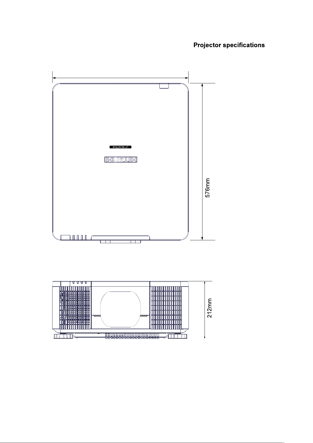
English - 69
Dimensions
500mm
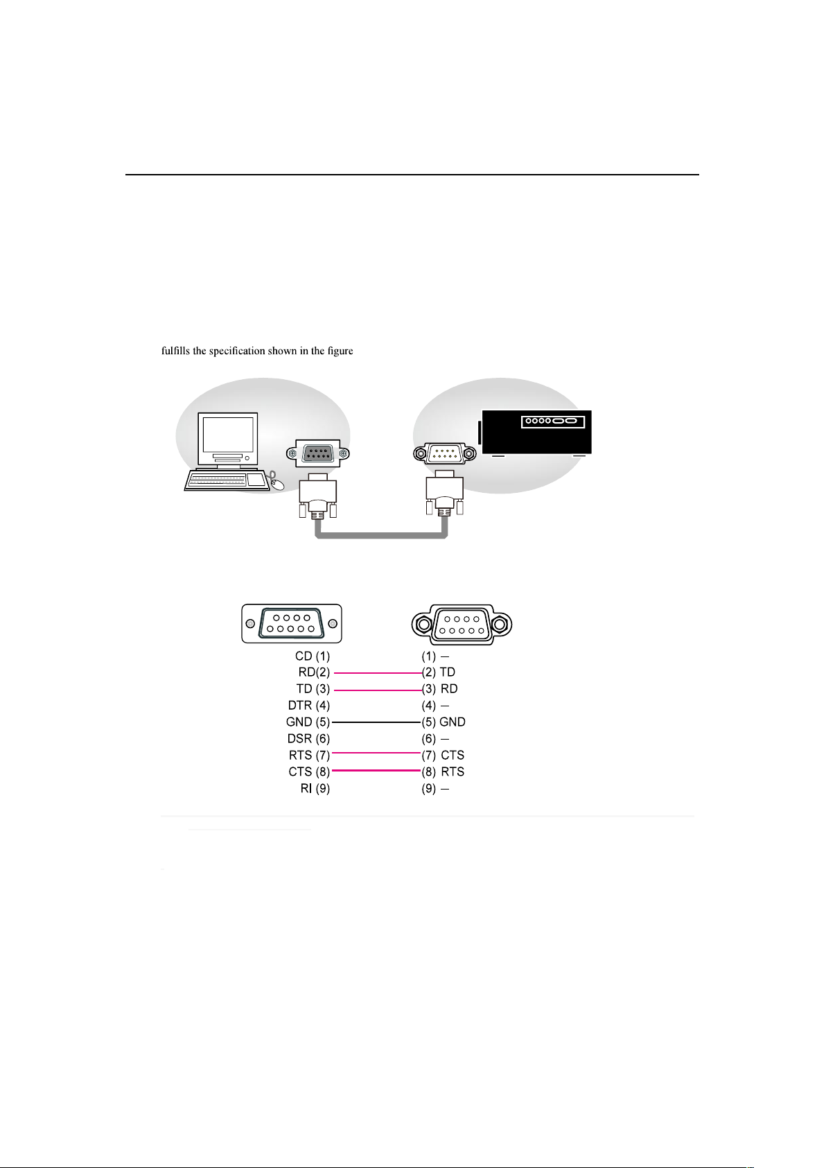
English - 70
Communication settings
Communication settings
RS-232 Communication
When the projector connects to the computer by RS-232 communication, the projector can be
controlled with RS-232 commands from the computer. For details of RS-232 commands, refer to RS-
232 Communication command table.
Connection
1. Turn off the projector and the computer.
2. Connect the projector's RS232 port and the computer's RS-232 port with a RS-232 cable (straight) . Use the cable that
3. Turn the computer on, and after the computer has started up turn the projector on.
1
2
3
4 5
1
2345
789
6
98
7
6
RS-232 port of
the projector
RS-232 port of
the computer
RS-232 cable
(
straight
)
RS-232
RS-232
Note: In case of replacement and RS-232 cable (cross) has been installed, please add a packed RS-232 cable (cross) to
make connection correctly.
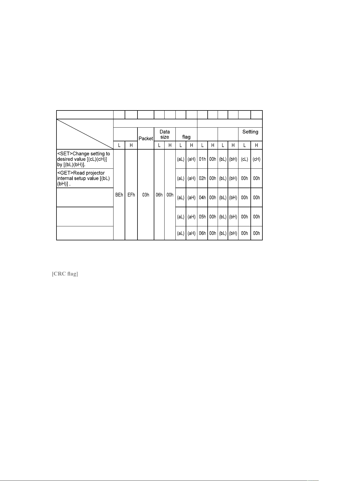
English - 71
Communication settings
1. Protocol
19200bps,8N1
2. Command format
("h" shows hexadecimal)
Byte Number 0 1 2 3 4 5 6
7 8 9 10 11 12
Command
Action
Header Data
Header
code
CRC
Action Type
code
<INCREMENT>
Increment setup value
[(bL)(bH)] by 1.
<DECREMENT>
Decrement setup value
[(bL)(bH)] by 1.
<EXECUTE> Run a
command [(bL)(bH)].
[Header code] [Packet] [Data size]
Set [BEh, EFh, 03h, 06h, 00h] to byte number 0~4.
For byte number 5, 6, refer to RS-232 Communication command table.
[Action]
Set functional code to byte number 7, 8.
<SET> = [01h, 00h], <GET> = [02h, 00h], <INCREMENT> =[04h, 00h]
<DECREMENT> = [05h, 00h], <EXECUTE> = [06h, 00h]
Refer to RS232 Communication command table
[Type] [Setting code]
For byte number 9~12 , , refer to RS-232 Communication command table.

English - 72
Communication settings
3. Response code / Error code
("h" shows hexadecimal)
4. ACK reply : 06h
When the projector receives the Set, Increment, Decrement or Execute , command correctly, the projector changes the
5. NAK reply : 15h
When the projector cannot understand the received command, the projector , returns the error code. In such a case, check
the sending code and send the same command again.
6. Error reply : 1Ch + 0000h
When the projector cannot execute the received command for any reasons, the projector returns the error code. In such a
case, check the sending code and the setting status of the projector
7. Data reply : 1Dh + xxxxh
When the projector receives the GET command correctly, the projector returns the response code and 2 bytes of data.
Note
suitable cables.
-Provide an interval of at least 40ms between the response code and any other code.
-Commands are not accepted during warm-up.
code to the computer.
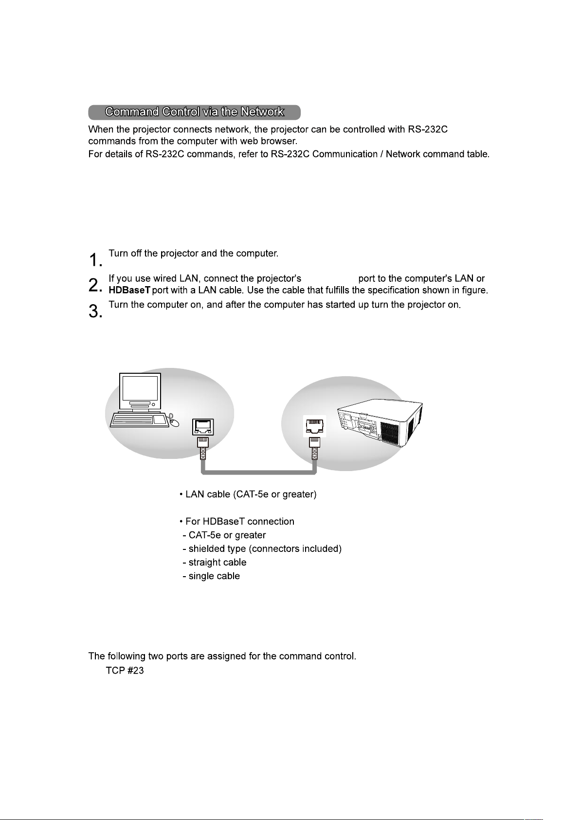
English - 73
Communication settings
LAN
LAN or
HDBaseT port
Connection
HDBaseT
TM
or
Communication Port
English - 74
Communication settings
Command control settings
[TCP #23]
1. Command format
2.
Response code / Error code
ACK reply : 06h
NAK reply : 15h
Error reply : 1Ch + 0000h
Data reply : 1Dh + xxxxh
NOTE
English - 75
Communication settings
Communication command table
Hitachi Command
Function Operation
Header Data (7 bytes) Command Data (6 bytes)
Description
Header
Code
Packet Data Size CRC Action Type
Setting
Code
Main
Input Source
Set
HDMI 1 BE EF 03 06 00 0E D2 01 00 00 20 03 00
HDMI 2 BE EF 03 06 00 6E D6 01 00 00 20 0D 00
Computer In 1 BE EF 03 06 00 FE D2 01 00 00 20 00 00
Computer In 2 BE EF 03 06 00 3E D0 01 00 00 20 04 00
HDBaseT BE EF 03 06 00 AE DE 01 00 00 20 11 00
SDI BE EF 03 06 00 5E DE 01 00 00 20 12 00
DVI-D BE EF 03 06 00 AE D4 01 00 00 20 09 00
Get BE EF 03 06 00 CD D2 02 00 00 20 00 00
PinP
Set
Off BE EF 03 06 00 3E 26 01 00 10 23 00 00
On BE EF 03 06 00 5E 27 01 00 10 23 02 00
Get BE EF 03 06 00 0D 26 02 00 10 23 00 00
PinP
Selection
Set
HDMI 1 BE EF 03 06 00 B6 23 01 00 02 23 03 00
HDMI 2 BE EF 03 06 00 D6 27 01 00 02 23 0D 00
Computer In 1 BE EF 03 06 00 46 23 01 00 02 23 00 00
Computer In 2 BE EF 03 06 00 86 21 01 00 02 23 04 00
HDBaseT BE EF 03 06 00 16 2F 01 00 02 23 11 00
SDI BE EF 03 06 00 E6 2F 01 00 02 23 12 00
DVI-D BE EF 03 06 00 16 25 01 00 02 23 09 00
Get BE EF 03 06 00 75 23 02 00 02 23 00 00
PinP
Position
Set
Top left BE EF 03 06 00 02 23 01 00 01 23 00 00
Top right BE EF 03 06 00 92 22 01 00 01 23 01 00
Bottom left BE EF 03 06 00 62 22 01 00 01 23 02 00
Bottom right BE EF 03 06 00 F2 23 01 00 01 23 03 00
PbyP BE EF 03 06 00 C2 2E 01 00 01 23 10 00
Get BE EF 03 06 00 31 23 02 00 01 23 00 00
Color Space
Set
Auto BE EF 03 06 00 02 68 01 00 71 22 00 00
REC709 BE EF 03 06 00 92 69 01 00 71 22 01 00
REC601 BE EF 03 06 00 62 69 01 00 71 22 02 00
RGB PC BE EF 03 06 00 F2 68 01 00 71 22 03 00
RGB Video BE EF 03 06 00 C2 6A 01 00 71 22 04 00
Get BE EF 03 06 00 31 68 02 00 71 22 00 00
3D Format
Set
Off BE EF 03 06 00 DA 58 01 00 8B 22 00 00
Auto BE EF 03 06 00 4A 59 01 00 8B 22 01 00
Side by Side BE EF 03 06 00 BA 59 01 00 8B 22 02 00
Top and Bottom BE EF 03 06 00 2A 58 01 00 8B 22 03 00
Frame Seqential BE EF 03 06 00 1A 5A 01 00 8B 22 04 00
Get BE EF 03 06 00 E9 58 02 00 8B 22 00 00
3D - Eye
Swap
Set
Normal BE EF 03 06 00 AE 59 01 00 8C 22 00 00
Reverse BE EF 03 06 00 3E 58 01 00 8C 22 01 00
Get BE EF 03 06 00 9D 59 02 00 8C 22 00 00
3D - DLP
Link
Set
Off BE EF 03 06 00 52 58 01 00 8D 22 00 00
On BE EF 03 06 00 C2 59 01 00 8D 22 01 00
Get BE EF 03 06 00 61 58 02 00 8D 22 00 00
Magnify
Increment BE EF 03 06 00 1A D2 04 00 07 30 00 00
Decrement BE EF 03 06 00 CB D3 05 00 07 30 00 00
Get BE EF 03
06 00 7C D2 02 00 07 30 00 00
Horz Shift
Increment BE EF 03 06 00 5B 5F 04 00 94 22 00 00
Decrement BE EF 03 06 00 8A 5E 05 00 94 22 00 00
Get BE EF 03 06 00 3D 5F 02 00 94 22 00 00
Vert Shift
Increment BE EF 03 06 00 A7 5E 04 00 95 22 00 00
Decrement BE EF 03 06 00 76 5F 05 00 95 22 00 00
Get BE EF 03 06 00 C1 5E 02 00 95 22 00 00
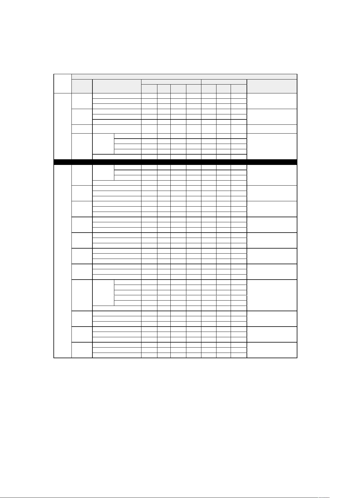
English - 76
Communication settings
Communication command table (continue)
Hitachi Command
Function Operation
Header Data (7 bytes) Command Data (6 bytes)
Description
Header
Code
Packet Data Size CRC Action Type
Setting
Code
Main
Horz Shift
Increment BE EF 03 06 00 AE D7 04 00 10 30 00 00
Decrement BE EF 03 06 00 7F D6 05 00 10 30 00 00
Get BE EF 03 06 00 C8 D7 02 00 10 30 00 00
Vert Shift
Increment BE EF 03 06 00 52 D6 04 00 11 30 00 00
Decrement BE EF 03 06 00 83 D7 05 00 11 30 00 00
Get BE EF 03 06 00 34 D6 02 00 11 30 00 00
Magnify &
Shift Reset
Execute BE EF 03 06 00 EC D6 06 00 17 70 00 00
"No Signal
(Start up)"
Set
Logo BE EF 03 06 00 CB E3 01 00 04 30 40 00
Black BE EF 03 06 00 AB D1 01 00 04 30 06 00
Blue BE EF 03 06 00 FB D2 01 00 04 30 03 00
White BE EF 03 06 00 5B D1 01 00 04 30 05 00
Get BE EF 03 06 00 38 D2 02 00 04 30 00 00
Picture
Picture
Mode
Set
High Bright BE EF 03 06 00 23 CA 01 00 BA 30 50 00
Presentation BE EF 03 06 00 B3 CB 01 00 BA 30 51 00
Video BE EF 03 06 00 43 CB 01 00 BA 30 52 00
Get BE EF 03 06 00 10 F6 02 00 BA 30 00 00
Brightness
Increment BE EF 03 06 00 EF D2 04 00 03 20 00 00
Decrement BE EF 03 06 00 3E D3 05 00 03 20 00 00
Get BE EF 03 06 00 89 D2 02 00 03 20 00 00
Contrast
Increment BE EF 03 06 00 9B D3 04 00 04 20 00 00
Decrement BE EF 03 06 00 4A D2 05 00 04 20 00 00
Get BE EF 03 06 00 FD D3 02 00 04 20 00 00
Color
Increment BE EF 03 06 00 D3 72 04 00 02 22 00 00
Decrement BE EF 03 06 00 02 73 05 00 02 22 00 00
Get BE EF 03 06 00 B5 72 02 00 02 22 00 00
Tint
Increment BE EF 03 06 00 2F 73 04 00 03 22 00 00
Decrement BE EF 03 06 00 FE 72 05 00 03 22 00 00
Get BE EF 03 06 00 49 73 02 00 03 22 00 00
Sharpness
Increment BE EF 03 06 00 97 72 04 00 01 22 00 00
Decrement BE EF 03 06 00 46 73 05 00 01 22 00 00
Get BE EF 03 06 00 F1 72 02 00 01 22 00 00
Noise
Reduction
Increment BE EF 03 06 00 7F 70 04 00 0F 22 00 00
Decrement BE EF 03 06 00 AE 71 05 00 0F 22 00 00
Get BE EF 03 06 00 19 70 02 00 0F 22 00 00
Color
Temperature
Set
5400K BE EF 03 06 00 5B E2 01 00 B0 30 36 00
6500K BE EF 03 06 00 AB C5 01 00 B0 30 41 00
7500K BE EF 03 06 00 0B C3 01 00 B0 30 4B 00
9300K BE EF 03 06 00 6B CD 01 00 B0 30 5D 00
Native BE EF 03 06 00 0B B4 01 00 B0 30 FF 00
Get BE EF 03 06 00 C8 F5 02 00 B0 30 00 00
White
Balance -
Red Offset
Increment BE EF 03 06 00 62 F5 04 00 B5 30 00 00
Decrement BE EF 03 06 00 B3 F4 05 00 B5 30 00 00
Get BE EF 03 06 00 04 F5 02 00 B5 30 00 00
White
Balance -
Green Offset
Increment BE EF 03 06 00 26 F5 04 00 B6 30 00 00
Decrement BE EF 03 06 00 F7 F4 05 00 B6 30 00 00
Get BE EF 03 06 00 40 F5 02 00 B6 30 00 00
White
Balance -
Blue Offset
Increment BE EF 03 06 00 DA F4 04 00 B7 30 00 00
Decrement BE EF 03 06 00 0B F5 05 00 B7 30 00 00
Get BE EF 03 06 00 BC F4 02 00 B7 30 00 00
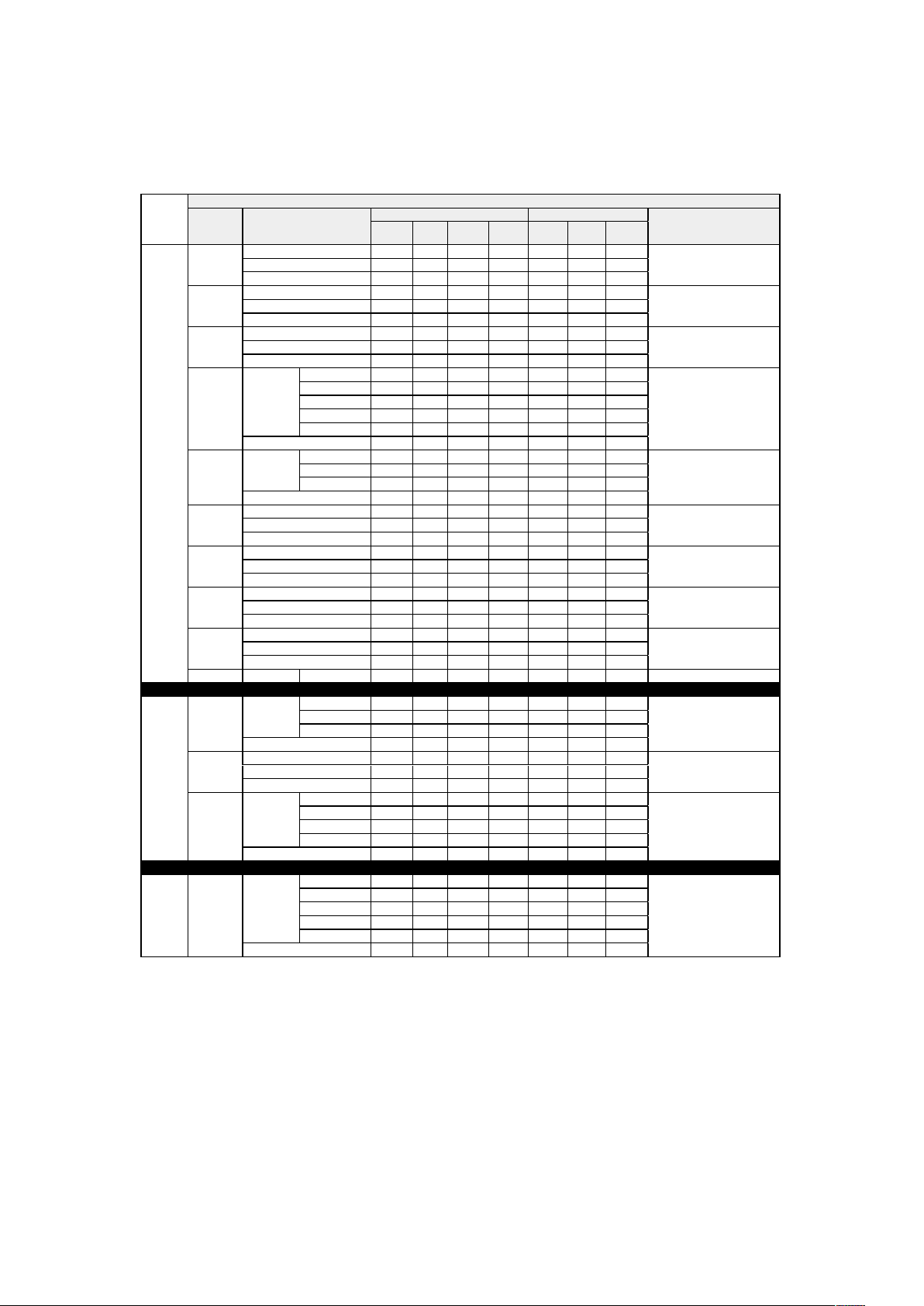
English - 77
Communication settings
Communication command table (continue)
Hitachi Command
Function Operation
Header Data (7 bytes) Command Data (6 bytes)
Description
Header
Code
Packet Data Size CRC Action Type
Setting
Code
Picture
White
Balance -
Red Gain
Increment BE EF 03 06 00 52 F4 04 00 B1 30 00 00
Decrement BE EF 03 06 00 83 F5 05 00 B1 30 00 00
Get BE EF 03 06 00 34 F4 02 00 B1 30 00 00
White
Balance -
Green Gain
Increment BE EF 03 06 00 16 F4 04 00 B2 30 00 00
Decrement BE EF 03 06 00 C7 F5 05 00 B2 30 00 00
Get BE EF 03 06 00 70 F4 02 00 B2 30 00 00
White
Balance -
Blue Gain
Increment BE EF 03 06 00 EA F5 04 00 B3 30 00 00
Decrement BE EF 03 06 00 3B F4 05 00 B3 30 00 00
Get BE EF 03 06 00 8C F5 02 00 B3 30 00 00
Aspect
Set
4:3 BE EF 03 06 00 9E D0 01 00 08 20 00 00
16:10 BE EF 03 06 00 3E D6 01 00 08 20 0A 00
16:9 BE EF 03 06 00 0E D1 01 00 08 20 01 00
Normal BE EF 03 6 00 5E DD 01 00 08 20 10 00
Native BE EF 03 6 00 5E D7 01 00 08 20 08 00
Get BE EF 03 06 00 AD D0 02 00 08 20 00 00
Over Scan
Set
Off BE EF 03 06 00 AB D4 01 00 1C 30 00 00
Crop BE EF 03 06 00 3B D5 01 00 1C 30 01 00
Zoom BE EF 03 06 00 CB D5 01 00 1C 30 02 00
Get BE EF 03 06 00 98 D4 02 00 1C 30 00 00
V Position
Increment BE EF 03 06 00 6B 83 04 00 00 21 00 00
Decrement BE EF 03 06 00 BA 82 05 00 00 21 00 00
Get BE EF 03 06 00 0D 83 02 00 00 21 00 00
H Position
Increment BE EF 03 06 00 97 82 04 00 01 21 00 00
Decrement BE EF 03 06 00 46 83 05 00 01 21 00 00
Get BE EF 03 06 00 F1 82 02 00 01 21 00 00
H Phase
Increment BE EF 03 06 00 2F 83 04 00 03 21 00 00
Decrement BE EF 03 06 00 FE 82 05 00 03 21 00 00
Get BE EF 03 06 00 49 83 02 00 03 21 00 00
H Size
Increment BE EF 03 06 00 D3 82 04 00 02 21 00 00
Decrement BE EF 03 06 00 02 83 05 00 02 21 00 00
Get BE EF 03 06 00 B5 82 02 00 02 21 00 00
Auto Adjust Execute BE EF 03 06 00 91 D0 06 00 0A 20 00 00
Laser
Power Mode
Set
Eco BE EF 03 06 00 AB 22 01 00 00 33 01 00
Normal BE EF 03 06 00 3B 23 01 00 00 33 00 00
Custom BE EF 03 06 00 3B 37 01 00 00 33 30 00
Get BE EF 03 06 00 08 23 02 00 00 33 00 00
Power Level
Increment BE EF 03 06 00 1A 22 04 00 07 33 00 00
Decrement BE EF 03 06 00 CB 23 05 00 07 33 00 00
Get BE EF 03 06 00 7C 22 02 00 07 33 00 00
High
Altitude
Set
Normal BE EF 03 06 00 E3 12 01 00 00 4C 00 00
High-1 BE EF 03 06 00 73 13 01 00 00 4C 01 00
High-2 BE EF 03 06 00 83 13 01 00 00 4C 02 00
Auto BE EF 03 06 00 23 1F 01 00 00 4C 10 00
Get BE EF 03 06 00 D0 12 02 00 00 4C 00 00
Advanced Installation
Set
Front Tabletop BE EF 03 06 00
C7 D2 01 00 01 30 00 00
Front Ceiling BE EF 03 06 00 37 D2 01 00 01 30 03 00
Rear Tabletop BE EF 03 06 00 57 D3 01 00 01 30 01 00
Rear Ceiling BE EF 03 06 00 A7 D3 01 00 01 30 02 00
Rear Ceiling BE EF 03 06 00 A7 D3 01 00 01 30 02 00
Get BE EF 03 06 00 F4 D2 02 00 01 30 00 00
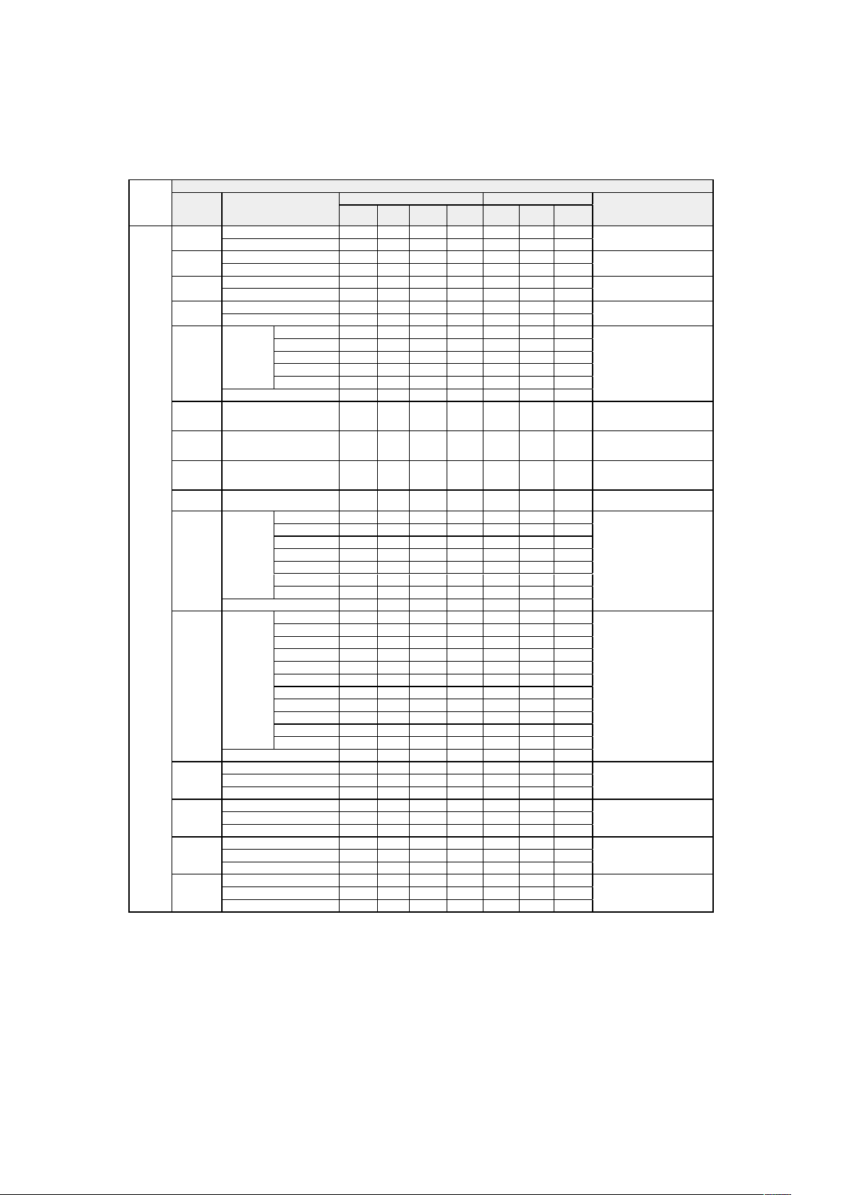
English - 78
Communication settings
Communication command table (continue)
Hitachi Command
Function Operation
Header Data (7 bytes) Command Data (6 bytes)
Description
Header
Code
Packet Data Size CRC Action Type
Setting
Code
Advanced
Lens Control
- Zoom
Increment BE EF 03 06 00 96 92 04 00 01 24 00 00
Decrement BE EF 03 06 00 47 93 05 00 01 24 00 00
Lens Control
- Focus
Increment BE EF 03 06 00 6A 93 04 00 00 24 00 00
Decrement BE EF 03 06 00 BB 92 05 00 00 24 00 00
Lens Control
- Shift V
Increment BE EF 03 06 00 D2 92 04 00 02 24 00 00
Decrement BE EF 03 06 00 03 93 05 00 02 24 00 00
Lens Control
- Shift H
Increment BE EF 03 06 00 2E 93 04 00 03 24 00 00
Decrement BE EF 03 06 00 FF 92 05 00 03 24 00 00
Lens
Memory
Index
Set
1 BE EF 03 06 00 4B 92 01 00 07 24 00 00
2 BE EF 03 06 00 DB 93 01 00 07 24 01 00
3 BE EF 03 06 00 2B 93 01 00 07 24 02 00
4 BE EF 03 06 00 BB 92 01 00 07 24 03 00
5 BE EF 03 06 00 8B 90 01 00 07 24 04 00
Get BE EF 03 06 00 78 92 02 00 07 24 00 00
Lens
Memory
Load
Execute BE EF 03 06 00 E8 90 06 00 08 24 00 00
Lens
Memory
Save
Execute BE EF 03 06 00 14 91 06 00 09 24 00 00
Lens
Memory
Clear
Execute BE EF 03 06 00 50 91 06 00 0A 24 00 00
Lens
Centering
Execute BE EF 03 06 00 B8 93 06 00 04 24 00 00
Gamma
Set
1.0 BE EF 03 06 00 FB DB 01 00 A0 30 64 00
1.8 BE EF 03 06 00 3B 86 01 00 A0 30 B4 00
2.0 BE EF 03 06 00 FB A6 01 00 A0 30 C8 00
2.2 BE EF 03 06 00 FB A9 01 00 A0 30 DC 00
2.35 BE EF 03 06 00 CB BF 01 00 A0 30 EB 00
2.5 BE EF 03 06 00 9B B3 01 00 A0 30 FA 00
Dicom Sim. BE EF 03 06 00 8B F0 01 00 A0 30 FF FF
Get BE EF 03 06 00 08 F1 02 00 A0 30 00 00
Pattern
Set
Off BE EF 03 06 00 FB FA 01 00 80 30 00 00
White BE EF 03 06 00 0B F5 01 00 80 30 17 00
Black BE EF 03 06 00 FB F0 01 00 80 30 18 00
Red BE EF 03 06 00 FB F5 01 00 80 30 14 00
Green BE EF 03 06 00 6B F4 01 00 80 30 15 00
Blue BE EF 03 06 00 9B F4 01 00 80 30 16 00
Checkerboard BE EF 03 06 00 AB F3 01 00 80 30 1D 00
CrossHatch BE EF 03 06 00 5B F6 01 00 80 30 12 00
V Burst BE EF 03 06 00 CB F7 01 00 80 30 13 00
H Burst BE EF 03 06 00 5B F3 01 00 80 30 1E 00
Color Bar BE EF 03 06 00 AB F6 01 00 80 30 11 00
Get BE EF 03 06 00 C8 FA 02 00 80 30 00 00
Red Hue
Increment BE EF 03 06 00 6A 63 04 00 00 27 00 00
Decrement BE EF 03 06 00 BB 62 05 00 00 27 00 00
Get BE EF 03 06 00 0C 63 02 00 00 27 00 00
Red
Saturation
Increment BE EF 03 06 00 AA 67 04 00 10 27 00 00
Decrement BE EF 03 06 00 7B 66 05 00 10 27 00 00
Get BE EF 03 06 00 CC 67 02 00 10 27 00 00
Red Gain
Increment
BE EF 03 06 00 AA 68 04 00 20 27 00 00
Decrement BE EF 03 06 00 7B 69 05 00 20 27 00 00
Get BE EF 03 06 00 CC 68 02 00 20 27 00 00
Green Hue
Increment BE EF 03 06 00 D2 62 04 00 02 27 00 00
Decrement BE EF 03 06 00 03 63 05 00 02 27 00 00
Get BE EF 03 06 00 B4 62 02 00 02 27 00 00
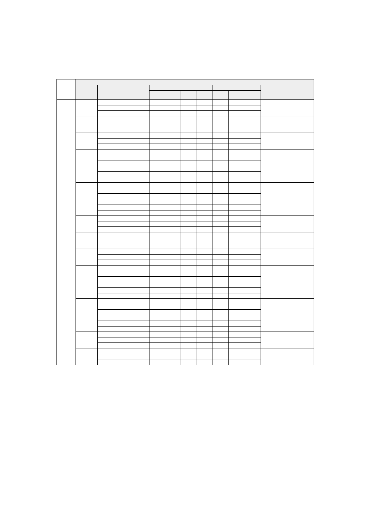
English - 79
Communication settings
Communication command table (continue)
Hitachi Command
Function Operation
Header Data (7 bytes) Command Data (6 bytes)
Description
Header
Code
Packet Data Size CRC Action Type
Setting
Code
Advanced
Green
Saturation
Increment BE EF 03 06 00 12 66 04 00 12 27 00 00
Decrement BE EF 03 06 00 C3 67 05 00 12 27 00 00
Get BE EF 03 06 00 74 66 02 00 12 27 00 00
Green Gain
Increment BE EF 03 06 00 12 69 04 00 22 27 00 00
Decrement BE EF 03 06 00 C3 68 05 00 22 27 00 00
Get BE EF 03 06 00 74 69 02 00 22 27 00 00
Blue Hue
Increment BE EF 03 06 00 5A 62 04 00 04 27 00 00
Decrement BE EF 03 06 00 8B 63 05 00 04 27 00 00
Get BE EF 03 06 00 3C 62 02 00 04 27 00 00
Blue
Saturation
Increment BE EF 03 06 00 9A 66 04 00 14 27 00 00
Decrement BE EF 03 06 00 4B 67 05 00 14 27 00 00
Get BE EF 03 06 00 FC 66 02 00 14 27 00 00
Blue Gain
Increment BE EF 03 06 00 9A 69 04 00 24 27 00 00
Decrement BE EF 03 06 00 4B 68 05 00 24 27 00 00
Get BE EF 03 06 00 FC 69 02 00 24 27 00 00
Cyan Hue
Increment BE EF 03 06 00 2E 63 04 00 03 27 00 00
Decrement BE EF 03 06 00 FF 62 05 00 03 27 00 00
Get BE EF 03 06 00 48 63 02 00 03 27 00 00
Cyan
Saturation
Increment BE EF 03 06 00 EE 67 04 00 13 27 00 00
Decrement BE EF 03 06 00 3F 66 05 00 13 27 00 00
Get BE EF 03 06 00 88 67 02 00 13 27 00 00
Cyan Gain
Increment BE EF 03 06 00 EE 68 04 00 23 27 00 00
Decrement BE EF 03 06 00 3F 69 05 00 23 27 00 00
Get BE EF 03 06 00 88 68 02 00 23 27 00 00
Magenta
Hue
Increment BE EF 03 06 00 A6 63 04 00 05 27 00 00
Decrement BE EF 03 06 00 77 62 05 00 05 27 00 00
Get BE EF 03 06 00 C0 63 02 00 05 27 00 00
Magenta
Saturation
Increment BE EF 03 06 00 66 67 04 00 15 27 00 00
Decrement BE EF 03 06 00 B7 66 05 00 15 27 00 00
Get BE EF 03 06 00 00 67 02 00 15 27 00 00
Magenta
Gain
Increment BE EF 03 06 00 66 68 04 00 25 27 00 00
Decrement BE EF 03 06 00 B7 69 05 00 25 27 00 00
Get BE EF 03 06 00 00 68 02 00 25 27 00 00
Yellow Hue
Increment BE EF 03 06 00 96 62 04 00 01 27 00 00
Decrement BE EF 03 06 00 47 63 05 00 01 27 00 00
Get BE EF 03 06 00 F0 62 02 00 01 27 00 00
Yellow
Saturation
Increment BE EF 03 06 00 56 66 04 00 11 27 00 00
Decrement BE EF 03 06 00 87 67 05 00 11 27 00 00
Get BE EF 03 06 00 30 66 02 00 11 27 00 00
Yellow Gain
Increment BE EF 03 06 00 56 69 04 00 21 27 00 00
Decrement BE EF 03 06 00 87 68 05 00 21 27 00 00
Get BE EF 03 06 00 30 69 02 00 21 27 00 00
White Gain
R
Increment BE EF 03 06 00 CA 6A 04 00 28 27 00 00
Decrement BE EF 03 06 00 1B 6B 05 00 28 27 00 00
Get BE EF 03 06 00 AC 6A 02 00 28 27 00 00
White Gain
G
Increment BE EF 03 06 00 72 6B 04 00 2A 27 00 00
Decrement BE EF 03 06 00 A3 6A 05 00 2A 27 00 00
Get BE EF 03 06 00 14 6B 02 00 2A 27 00 00
English - 80
Communication settings
Communication command table (continue)
Hitachi Command
Function Operation
Header Data (7 bytes) Command Data (6 bytes)
Description
Header
Code
Packet Data Size CRC Action Type
Setting
Code
Advanced
White Gain
B
Increment BE EF 03 06 00 FA 6B 04 00 2C 27 00 00
Decrement BE EF 03 06 00 2B 6A 05 00 2C 27 00 00
Get BE EF 03 06 00 9C 6B 02 00 2C 27 00 00
H Keystone
Increment BE EF 03 06 00 8F D0 04 00 0B 20 00 00
Decrement BE EF 03 06 00 5E D1 05 00 0B 20 00 00
Get BE EF 03 06 00 E9 D0 02 00 0B 20 00 00
V Keystone
Increment BE EF 03 06 00 DF D3 04 00 07 20 00 00
Decrement BE EF 03 06 00 0E D2 05 00 07 20 00 00
Get BE EF 03 06 00 B9 D3 02 00 07 20 00 00
Rotation
Increment BE EF 03 06 00 AB 99 04 00 70 21 00 00
Decrement BE EF 03 06 00 7A 98 05 00 70 21 00 00
Get BE EF 03 06 00 CD 99 02 00 70 21 00 00
H
Pincushion /
Barrel
Increment BE EF 03 06 00 57 97 04 00 41 21 00 00
Decrement BE EF 03 06 00 86 96 05 00 41 21 00 00
Get BE EF 03 06 00 31 97 02 00 41 21 00 00
V
Pincushion /
Barrel
Increment BE EF 03 06 00 9B 97 04 00 44 21 00 00
Decrement BE EF 03 06 00 4A 96 05 00 44 21 00 00
Get BE EF 03 06 00 FD 97 02 00 44 21 00 00
Top Left
Corner - x
Increment BE EF 03 06 00 57 89 04 00 21 21 00 00
Decrement BE EF 03 06 00 86 88 05 00 21 21 00 00
Get BE EF 03 06 00 31 89 02 00 21 21 00 00
Top Left
Corner - y
Increment BE EF 03 06 00 13 89 04 00 22 21 00 00
Decrement BE EF 03 06 00 C2 88 05 00 22 21 00 00
Get BE EF 03 06 00 75 89 02 00 22 21 00 00
Top Right
Corner - x
Increment BE EF 03 06 00 EF 88 04 00 23 21 00 00
Decrement BE EF 03 06 00 3E 89 05 00 23 21 00 00
Get BE EF 03 06 00 89 88 02 00 23 21 00 00
Top Right
Corner - y
Increment BE EF 03 06 00 9B 89 04 00 24 21 00 00
Decrement BE EF 03 06 00 4A 88 05 00 24 21 00 00
Get BE EF 03 06 00 FD 89 02 00 24 21 00 00
Bottom Left
Corner - x
Increment BE EF 03 06 00 67 88 04 00 25 21 00 00
Decrement BE EF 03 06 00 B6 89 05 00 25 21 00 00
Get BE EF 03 06 00 01 88 02 00 25 21 00 00
Bottom Left
Corner - y
Increment BE EF 03 06 00 23 88 04 00 26 21 00 00
Decrement BE EF 03 06 00 F2 89 05 00 26 21 00 00
Get BE EF 03 06 00 45 88 02 00 26 21 00 00
Bottom
Right Corner
- x
Increment BE EF 03 06 00 DF 89 04 00 27 21 00 00
Decrement BE EF 03 06 00 0E 88 05 00 27 21 00 00
Get BE EF 03 06 00 B9 89 02 00 27 21 00 00
Bottom
Right Corner
- y
Increment BE EF 03 06 00 CB 8A 04 00 28 21 00 00
Decrement BE EF 03 06 00 1A 8B 05 00 28 21 00 00
Get BE EF 03 06 00 AD 8A 02 00 28 21 00 00
Warping -
Reset
Execute BE EF 03 06 00 F1 99 06 00 72 21 00 00
Blanking -
Top
Increment BE EF 03 06 00 8A DA 04 00 2B 30
00 00
Decrement BE EF 03 06 00 5B DB 05 00 2B 30 00 00
Get BE EF 03 06 00 EC DA 02 00 2B 30 00 00

