Loading ...
Loading ...
Loading ...
12
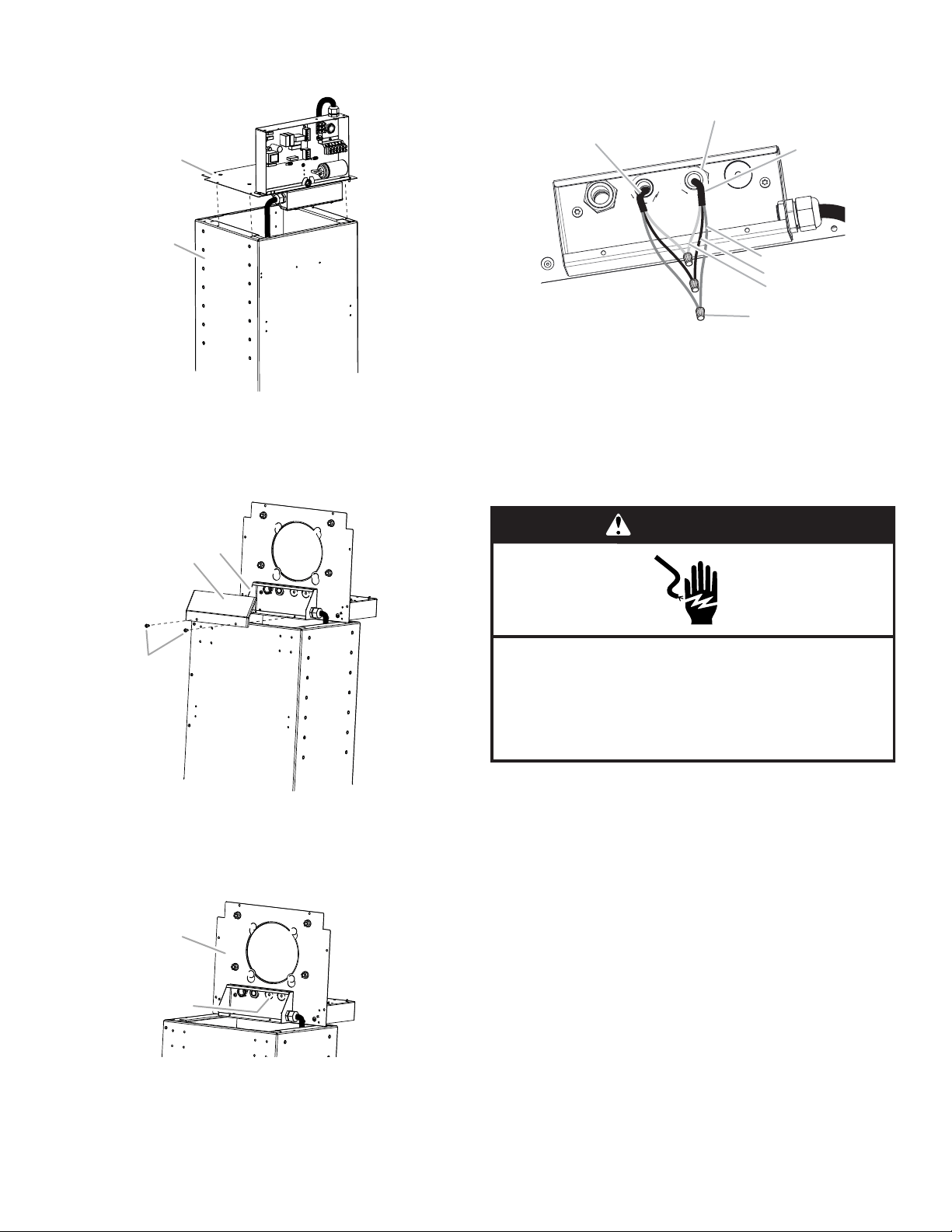
5. Lift module plate assembly from top of range hood module
and position it to rest on top of the module.
6. Using a T20
®
Torx
®
driver, remove (2) screws from the
electrical connection box on the bottom of the module
plate assembly.
7. Remove knockout labeled “Elec IN” from the module top
plate, and install UL listed or CSA approved strain relief.
8. Run the flexible 3 wire home power supply cable from
the ceiling through the strain relief and into the electrical
connection box.
9. Use UL listed wire connectors and connect the
black wires together.
10. Use UL listed wire connectors and connect the
white wires together.
11. Connect the green (or bare) ground wire from the home
power supply cable to the green (or green/yellow) ground
wire in the electrical box using a UL listed wire connector.
12. Tighten strain relief to secure the home power supply cable.
13. Reassemble the electrical connection box cover
on the bottom of the module plate assembly.
14. Reassemble the module plate assembly to the top of the
range hood module and tighten the (8) assembly screws.
15. Reaassemble the electrical box cover and wire race to the
front of the range hood module.
A. Module plate assembly
B. Range hood module
A. Electrical connection box cover
B. Screws (2)
C. Electrical connection box
A. Bottom of module top plate
B. Elec IN knockout
A
B
C
A
B
A
B
A. UL listed or CSA approved
strain relief
B. 3-wire flexible home power
supply cable
C. Green, bare or yellow/green
wires
D. Black wires
E. White wires
F. UL listed wire connectors (3)
G. 3-wire flexible power cable
from electrical box
A
B
G
C
D
E
F
WARNING
Electrical Shock Hazard
Electrically ground blower.
Connect ground wire to green and yellow ground wire
in terminal box.
Failure to do so can result in death or electrical shock.
Loading ...
Loading ...
Loading ...